

Page 1
T6200
/
T6200 H.O.
TowSport
OPERATION AND
MAINTENANCE
MANUAL
Page 2

Page 3
Welcome
You have selected one of the finest marine power packages available. It incorporates numerous design features to
ensure operating ease and durability.
With proper care and maintenance, you will enjoy using this product for many boating seasons. To ensure maximum
performance and carefree use, we ask that you thoroughly read this manual.
The Operation and Maintenance Manual contains specific instructions for using and maintaining your product. We
suggest that this manual remain with the product for ready reference whenever you are on the water.
Thank you for purchasing one of our products. We sincerely hope your boating will be pleasant!
Mercury Marine, Fond du Lac, Wisconsin, U.S.A.
Name / function:
John Pfeifer, President,
Mercury Marine
Read This Manual Thoroughly
IMPORTANT: If you do not understand any portion of this manual, contact your dealer. Your dealer can also provide a
demonstration of actual starting and operating procedures.
Notice
Throughout this publication, and on your power package, warnings, cautions, and notices, accompanied by the
8M0128975 617 eng
International Hazard Symbol !, may be used to alert the installer and user to special instructions concerning a
particular service or operation that may be hazardous if performed incorrectly or carelessly. Observe them carefully.
These safety alerts alone cannot eliminate the hazards that they signal. Strict compliance with these special instructions
while performing the service, plus common sense operation, are major accident prevention measures.
WARNING
!
Indicates a hazardous situation which, if not avoided, could result in death or serious injury.
!
CAUTION
Indicates a hazardous situation which, if not avoided, could result in minor or moderate injury.
NOTICE
Indicates a situation which, if not avoided, could result in engine or major component failure.
IMPORTANT: Identifies information essential to the successful completion of the task.
NOTE: Indicates information that helps in the understanding of a particular step or action.
IMPORTANT: The operator (driver) is responsible for the correct and safe operation of the boat, the equipment aboard,
and the safety of all occupants aboard. We strongly recommend that the operator read this Operation and Maintenance
Manual and thoroughly understand the operational instructions for the power package and all related accessories before
the boat is used.
WARNING
!
The engine exhaust from this product contains chemicals known to the state of California to cause cancer, birth
defects or other reproductive harm.
6.2L TowSport MPI
The serial numbers are the manufacturer’s keys to numerous engineering details that apply to your Mercury Marine
power package. When contacting Mercury Marine about service, always specify model and serial numbers.
Descriptions and specifications contained herein were in effect at the time this was approved for printing. Mercury
Marine, whose policies are based on continuous improvement, reserves the right to discontinue models at any time or to
change specifications or designs without notice and without incurring obligation.
© 2017 Mercury Marine
Page 4

Warranty Message
The product you have purchased comes with a limited warranty from Mercury Marine; the terms of the warranty are set forth
in the Warranty Manual included with the product. The Warranty Manual contains a description of what is covered, what is not
covered, the duration of coverage, how to best obtain warranty coverage, important disclaimers and limitations of
damages, and other related information. Please review this important information.
Mercury Marine products are designed and manufactured to comply with our own high quality standards, applicable industry
standards and regulations, as well as certain emissions regulations. At Mercury Marine every engine is operated and tested
before it is boxed for shipment to make sure that the product is ready for use. In addition, certain Mercury Marine products are
tested in a controlled and monitored environment, for up to 10 hours of engine run time, in order to verify and make a record of
compliance with applicable standards and regulations. All Mercury Marine product, sold as new, receives the applicable limited
warranty coverage, whether the engine participated in one of the test programs described above or not.
Copyright and Trademark Information
© MERCURY MARINE. All rights reserved. Reproduction in whole or in part without permission is prohibited.
Alpha, Axius, Bravo One, Bravo Two, Bravo Three, Circle M with Waves Logo, K‑planes, Mariner, MerCathode, MerCruiser,
Mercury, Mercury with Waves Logo, Mercury Marine, Mercury Precision Parts, Mercury Propellers, Mercury Racing,
MotorGuide, OptiMax, Quicksilver, SeaCore, Skyhook, SmartCraft, Sport‑Jet, Verado, VesselView, Zero Effort, Zeus, #1 On the
Water and We're Driven to Win are registered trademarks of Brunswick Corporation. Pro XS is a trademark of Brunswick
Corporation. Mercury Product Protection is a registered service mark of Brunswick Corporation.
Identification Records
Please record the following applicable information:
MerCruiser
Engine Model and Horsepower Engine Serial Number
Transom Assembly Serial Number (Sterndrive) Gear Ratio Sterndrive Unit Serial Number
Transmission Model (Inboard) Gear Ratio Transmission Serial Number
Propeller Number Pitch Diameter
Hull Identification Number (HIN) Purchase Date
Boat Manufacturer Boat Model Length
Exhaust Gas Emissions Certification Number (Europe Only)
Page 5

TABLE OF CONTENTS
Section 1 - Getting to Know Your Power Package
Adaptive Speed Control (ASC).................................................. 2
Identification............................................................................... 2
Engine Serial Number ........................................................ 2
Transmissions..................................................................... 3
ZF Marine Transmissions............................................... 3
Lanyard Stop Switch.................................................................. 3
Keep the Lanyard Stop Switch and Lanyard Cord in Good
Operating Condition............................................................. 4
Instrumentation.......................................................................... 4
VesselView........................................................................... 4
SmartCraft Digital Instruments............................................. 5
System Link Digital Instruments........................................... 5
Remote Controls (Non‑DTS Models)......................................... 6
Remote Control Features—Non‑DTS................................. 6
Gear Shifting...................................................................6
Section 2 - On the Water
Safe Boating Recommendations............................................. 14
Carbon Monoxide Exposure.................................................... 15
Be Alert To Carbon Monoxide Poisoning........................... 15
Stay Clear of Exhaust Areas.............................................. 15
Good Ventilation ................................................................ 15
Poor Ventilation ................................................................. 16
Basic Boat Operation .............................................................. 16
Launching and Boat Operation......................................... 16
Operation Chart............................................................ 16
Starting and Stopping the Engine..................................... 16
Starting the Engine....................................................... 16
Stopping the Engine..................................................... 17
Throttle Only Operation—TowSport Panel Mount............ 17
Freezing Temperature Operation..................................... 18
Drain Plug and Bilge Pump............................................... 18
Protecting People in the Water................................................ 18
While You Are Cruising...................................................... 18
While Boat Is Stationary..................................................... 18
Remote Controls (DTS Models)................................................. 7
Remote Controls................................................................. 7
Panel Mount Features........................................................ 7
TowSports Panel Mount Features...................................... 8
Electrical System Overload Protection....................................... 8
Visual and Audio Warning Systems......................................... 11
Service Engine Light and OBD‑M MIL Kit......................... 11
Testing the OBD‑M Malfunction Indicator Lamp
(MIL)............................................................................. 11
Audio Warning System..................................................... 11
Caution......................................................................... 12
Critical...........................................................................12
Nonconfigured Alarm–DTS Only.................................. 12
Testing the Audio Warning System.............................. 12
Guardian Strategy............................................................. 12
High‑Speed and High‑Performance Operation........................ 18
Passenger Safety in Pontoon Boats and Deck Boats.............. 18
Boats Having an Open Front Deck.....................................19
Boats With Front‑Mounted, Raised Pedestal Fishing Seats
........................................................................................... 19
Wave and Wake Jumping........................................................ 19
Impact with Underwater Hazards............................................. 20
Conditions Affecting Operation................................................ 20
Weight Distribution (Passengers and Gear) Inside the
Boat.................................................................................. 20
The Bottom of the Boat..................................................... 20
Cavitation.......................................................................... 21
Ventilation......................................................................... 21
Elevation and Climate....................................................... 21
Getting Started......................................................................... 21
20‑Hour Break‑In Period................................................... 21
After the Break‑In Period.................................................. 21
End of First Season Checkup........................................... 22
Section 3 - Specifications
Fuel Requirements................................................................... 24
Fuel Ratings....................................................................... 24
Using Reformulated (Oxygenated) Gasoline (USA Only).. 24
Gasoline Containing Alcohol.............................................. 24
Bu16 Butanol Fuel Blends............................................ 24
Methanol and Ethanol Fuel Blends...............................24
Engine Oil................................................................................ 24
6.2 MPI TowSport Engine Specifications................................. 25
Fluid Specifications.................................................................. 26
Engine............................................................................... 26
Transmission.................................................................... 26
Section 4 - Maintenance
Owner/Operator Responsibilities............................................. 28
Dealer Responsibilities............................................................ 28
Cleaning Care Recommendation............................................. 28
90-8M0128975 eng JUNE 2017 Page i
Cleaning Gauges.............................................................. 28
Cleaning Remote Controls................................................ 28
Maintenance............................................................................ 28
Page 6

Do‑It‑Yourself Maintenance Suggestions............................... 29
Inspection............................................................................... 29
MerCruiser Gas Inboard Inspection and Maintenance
Schedule................................................................................. 29
Daily Checks..................................................................... 29
After Each Use.................................................................. 29
Weekly Checks................................................................. 29
20 Hour Break In............................................................... 30
Annually or 100 Hours...................................................... 30
Three Years or 300 Hours................................................ 30
Five Years or 500 Hours................................................... 30
Engine Oil............................................................................... 30
Checking......................................................................... 30
Oil Level—Overfilled................................................... 31
Filling............................................................................... 31
Engine Oil Drain Pump.................................................... 32
Changing the Oil Filter..................................................... 33
Engine Coolant ‑ Closed‑Cooling........................................... 33
Checking......................................................................... 33
Filling............................................................................... 34
Changing ........................................................................ 35
Transmission Fluid................................................................. 35
Checking the Fluid Level Before Operation...................... 35
Checking the Fluid Level When Hot................................. 36
Changing.......................................................................... 36
Transmission Anodes—45IV and 46IV................................... 36
Transmission Remote Control Cable Adjustment .................. 37
Battery.................................................................................... 37
Multiple EFI Engine Battery Precautions......................... 37
Flame Arrestor........................................................................ 38
Fuel System Maintenance...................................................... 40
Fuel System.................................................................... 40
Fuel Line Inspection........................................................ 40
Water‑Separating Fuel Filter........................................... 40
Filter Housing Removal............................................... 40
Draining the Filter Housing..........................................41
Fuel Filter Inspection................................................... 41
Filter Housing Installation............................................ 41
Lubrication.............................................................................. 42
Transmission Linkage..................................................... 42
Serpentine Drive Belt.............................................................. 42
Serpentine Drive Belt Routing......................................... 42
Serpentine Belt Failure Identification............................... 43
Checking......................................................................... 44
Replacing........................................................................ 44
Flushing the Power Package—Models without a Flushing
Attachment ............................................................................ 45
The Boat Out of the Water................................................ 45
The Boat in the Water....................................................... 47
Flushing the Power Package—Models with a Flushing
Attachment ............................................................................ 48
Section 5 - Storage
Cold Weather or Extended Storage........................................ 54
Reformulated (Oxygenated) Gasolines (U.S.A. Only)..... 54
Fuel Containing Alcohol.................................................. 54
Preparing Power Package for Storage—MPI Models..... 54
Special Fuel Mix.......................................................... 55
Engine and Fuel System Preparation......................... 55
TowSport and Inboard Transmissions Extended
Storage............................................................................ 56
Section 6 - Troubleshooting
Diagnosing EFI Problems....................................................... 64
Engine Guardian System........................................................ 64
Troubleshooting Charts.......................................................... 64
Starter Motor Will Not Crank Engine, or Cranks Slowly.. 64
Engine Will Not Start or Is Hard to Start.......................... 64
Engine Runs Rough, Misses, or Backfires...................... 64
Poor Performance........................................................... 65
Section 7 - Customer Assistance Information
Draining the Seawater System............................................... 56
Draining the Raw Water.................................................. 56
Air Actuated Single‑Point Drain System (Standard
Cooling)........................................................................... 56
Air Actuated Single‑Point Drain System (Closed
Cooling)........................................................................... 59
Battery Storage....................................................................... 62
Recommissioning the Power Package................................... 62
Excessive Engine Temperature...................................... 65
Insufficient Engine Temperature..................................... 65
Low Engine Oil Pressure................................................. 65
Battery Will Not Recharge............................................... 65
Remote Control Is Difficult to Move or Makes Unusual
Sounds............................................................................ 66
Steering Wheel Jerks or Is Difficult to Turn..................... 66
Owner Service Assistance...................................................... 68
Local Repair Service......................................................... 68
Service Away From Home................................................ 68
Stolen Power Package..................................................... 68
Attention Required After Submersion............................... 68
Replacement Service Parts.............................................. 68
Parts and Accessories Inquiries....................................... 68
Resolving a Problem......................................................... 68
Page ii 90-8M0128975 eng JUNE 2017
Contact Information for Mercury Marine Customer Service
.......................................................................................... 69
Customer Service Literature................................................... 69
English Language............................................................. 69
Other Languages.............................................................. 70
Ordering Literature................................................................. 70
United States and Canada................................................ 70
Outside the United States and Canada............................ 70
Page 7

Section 8 - Checklists
Predelivery Inspection (PDI).................................................... 72 Customer Delivery Inspection (CDI)........................................ 73
Section 9 - Maintenance Log
Scheduled Maintenance Log................................................... 76 Vessel Maintenance Notes...................................................... 77
90-8M0128975 eng JUNE 2017 Page iii
Page 8

Page iv 90-8M0128975 eng JUNE 2017
Page 9

Section 1 - Getting to Know Your Power Package
Section 1 - Getting to Know Your Power Package
Table of Contents
Adaptive Speed Control (ASC)............................................... 2
Identification........................................................................... 2
Engine Serial Number .....................................................2
Transmissions..................................................................3
ZF Marine Transmissions ........................................ 3
Lanyard Stop Switch............................................................... 3
Keep the Lanyard Stop Switch and Lanyard Cord in
Good Operating Condition .............................................. 4
Instrumentation....................................................................... 4
VesselView ..................................................................... 4
SmartCraft Digital Instruments ....................................... 5
System Link Digital Instruments ..................................... 5
Remote Controls (Non‑DTS Models)...................................... 6
Remote Control Features—Non‑DTS.............................. 6
Gear Shifting ........................................................... 6
1
Remote Controls (DTS Models)............................................. 7
Remote Controls.............................................................. 7
Panel Mount Features..................................................... 7
TowSports Panel Mount Features................................... 8
Electrical System Overload Protection................................... 8
Visual and Audio Warning Systems..................................... 11
Service Engine Light and OBD‑M MIL Kit......................11
Testing the OBD‑M Malfunction Indicator Lamp (MIL)
.............................................................................. 11
Audio Warning System.................................................. 11
Caution .................................................................. 12
Critical ................................................................... 12
Nonconfigured Alarm–DTS Only ........................... 12
Testing the Audio Warning System ....................... 12
Guardian Strategy..........................................................12
90-8M0128975 eng JUNE 2017 Page 1
Page 10
Section 1 - Getting to Know Your Power Package
a
b
58539
a
b
61322
a
b
c
39307
Adaptive Speed Control (ASC)
This power package utilizes Adaptive Speed Control (ASC) to maintain the engine RPM that is demanded at the remote
control, regardless of the load change. As an example of how ASC functions, when the operator steers the boat into a hard turn
or is navigating at a slow on‑plane speed in following seas when boat control is needed without a lot of speed, the propulsion
control module will automatically adjust the engine to maintain the RPM without the operator changing the position of the
remote control throttle handle. ASC allows the operator to keep both hands on the steering wheel, which is safer, and the
operator can focus on the boating experience.
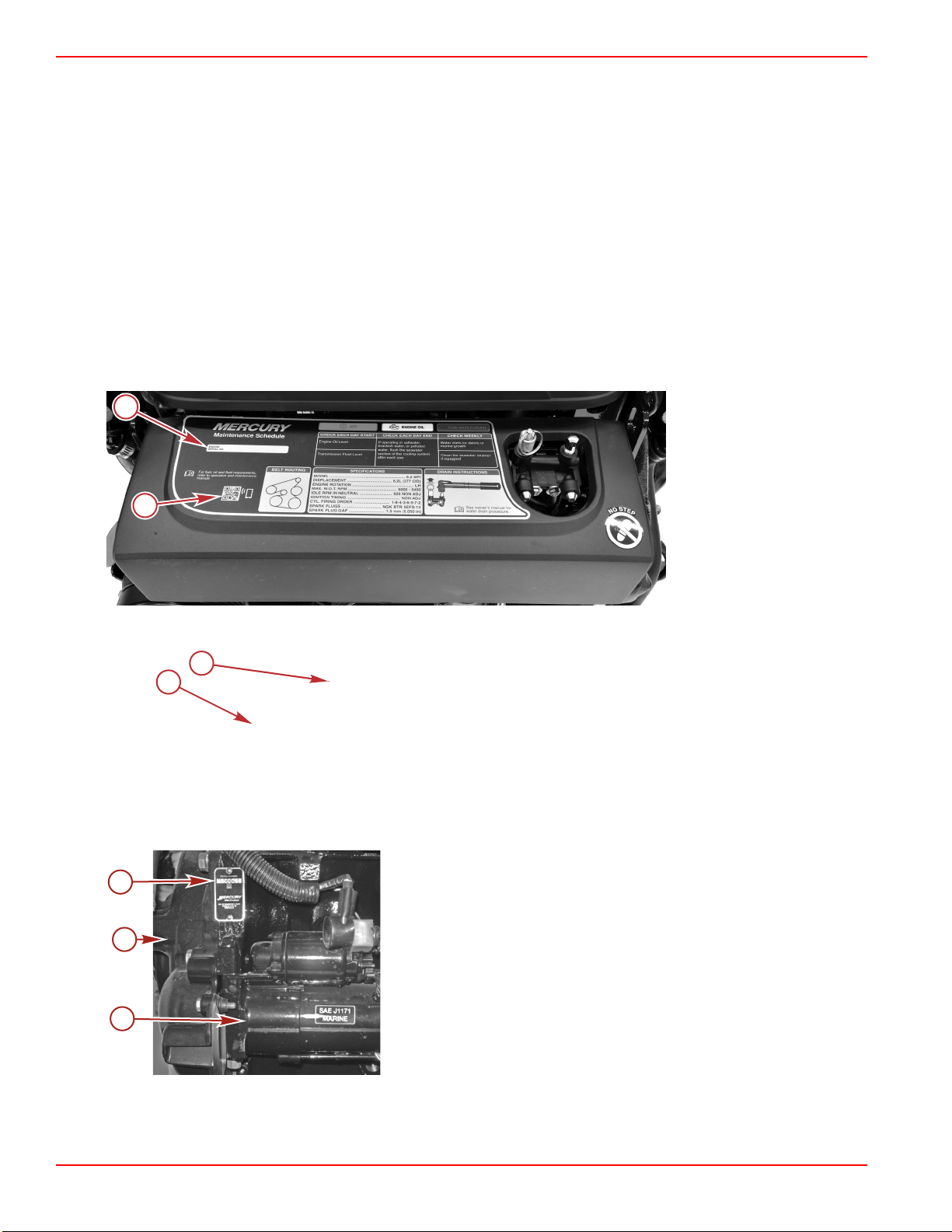
Identification
The serial numbers are the manufacturer's keys to numerous engineering details which apply to your MerCruiser power
package. When contacting MerCruiser about service, always specify model and serial numbers.
Engine Serial Number
The serial number is located in two places on the engine. One is on the engine specification decal located on the engine cover
or heat exchanger, and the other is secured to the starboard side of the engine block near the starter motor.
A quick reference code on the engine cover or heat exchanger can be used to access additional information about the engine
and safe boating practices.
Raw water cooled
a - Engine serial number
decal
b - Quick reference code
Freshwater cooled
a - Engine serial number decal
b - Quick reference code
Engine block location
a - Engine serial number plate
b - Flywheel housing
c - Starter motor
Page 2 90-8M0128975 eng JUNE 2017
Page 11
Section 1 - Getting to Know Your Power Package
58892
61400
58436
a
c
a
b
53910
OFF
RUN
ATTACH LANYARD
Transmissions
ZF Marine Transmissions
The ZF Marine transmission identification plates have the gear ratio, serial number, and model number listed.
NOTE: A digital and mechanical version of each type of transmission is available.
ZF 45IV V-drive (digital), 46IV V-drive similar
a - Transmission identification plate
Lanyard Stop Switch
A lanyard switch is designed to shut down the engine in the event the operator unexpectedly moves away from the helm, as
may happen in an accidental ejection. The lanyard is connected to the operator's personal flotation device or wrist.
A decal near the lanyard stop switch reminds the operator to attach the lanyard to his or her personal flotation device or wrist.
Accidental ejections, such as falling overboard, are more likely to occur in:
• Low‑sided sport boats
• Bass boats
• High‑performance boats
Accidental ejections can also occur from:
ZF 45C (digital) 63IV (digital)
a - Lanyard cord clip
b - Lanyard decal
c - Lanyard stop switch
90-8M0128975 eng JUNE 2017 Page 3
Page 12

Section 1 - Getting to Know Your Power Package
• Poor operating practices
• Sitting on the seat or gunwale at planing speeds
• Standing at planing speeds
• Operating at planing speeds in shallow or obstacle‑infested waters
• Releasing your grip on the steering wheel
• Carelessness caused by consuming alcohol or drugs
• High‑speed boating maneuvers
The lanyard is a cord usually between 122 and 152 cm (4 and 5 ft) long when stretched out, with an element on one end made
to be inserted into the switch, and a snap on the other end for attaching to the operator. The lanyard is coiled to make its at‑rest
condition as short as possible to minimize the likelihood of lanyard entanglement with nearby objects. Its stretched‑out length is
made to minimize the likelihood of accidental activation should the operator choose to move around in an area close to the
operator's normal position. The operator can shorten the lanyard by wrapping the lanyard around his wrist, or by tying a knot in
the lanyard.
Activation of the lanyard stop switch will stop the engine immediately, but the boat will continue to coast for some distance,
depending upon its velocity. While the boat is coasting, it can cause injury to anyone in the boat's path as it would under power.
Instruct all passengers on the proper starting and operating procedures should they be required to operate the boat in an
emergency.
WARNING
!
If the operator falls out of the boat, stop the engine immediately to reduce the possibility of serious injury or death from being
struck by the boat. Always properly connect the operator to the stop switch using a lanyard.
Accidental or unintended activation of the switch during normal operation is also a possibility. This could cause any, or all, of
the following potentially hazardous situations:
• Occupants could be thrown forward due to unexpected loss of forward motion, a particular concern for passengers in the
front of the boat who could be ejected over the bow and possibly struck by the propulsion or steering components.
• Loss of power and directional control in heavy seas, strong current, or high winds.
• Loss of control when docking.
WARNING
!
Avoid serious injury or death from deceleration forces resulting from accidental or unintended stop switch activation. The boat
operator should never leave the operator's station without first disconnecting the stop switch lanyard from the operator.
Keep the Lanyard Stop Switch and Lanyard Cord in Good Operating Condition
Before each use, ensure that the lanyard stop switch works properly. Start the engine, and then stop it by pulling the lanyard
cord. If the engine does not stop, have the switch repaired before operating the boat.
Before each use, inspect the lanyard cord to ensure that it is in good working condition and that there are no breaks, cuts, or
wear to the cord. Check that the clips on the ends of the cord are in good condition. Replace any damaged or worn lanyard
cords.
Instrumentation
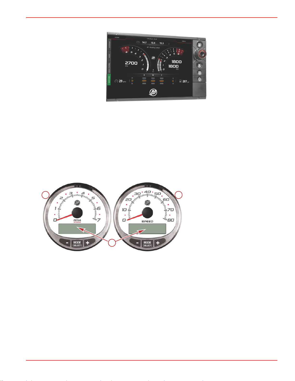
VesselView
There are several VesselView products available. VesselView will display all engine information, fault codes, vessel
information, basic navigation data, and system information. When an operating system error or failure occurs, VesselView
displays an alarm message.
VesselView may also be connected to other vessel systems such as GPS, generators, and chartplotters. This vessel
integration allows the operator to monitor and control a wide range of vessel systems from a single display.
Page 4 90-8M0128975 eng JUNE 2017
Page 13
Section 1 - Getting to Know Your Power Package
61325
a
b
c
c
50400
Refer to the VesselView operator's manual for more information.
VesselView
SmartCraft Digital Instruments
The SmartCraft instrument package augments the VesselView display. The instrument package may include:
• Tachometer
• Speedometer
• Engine coolant temperature
• Engine oil pressure
• Battery voltage
• Fuel consumption
• Engine operating hours
SmartCraft tachometer and speedometer
a - Tachometer
b - Speedometer
c - LCD display
The SmartCraft instrument package also aids in identifying fault codes associated with the engine audio warning system. The
SmartCraft instrument package displays critical engine alarm data and other potential problems on its LCD display.
For basic operation information on the SmartCraft instrument package and for details on the warning functions monitored by the
system, refer to the manual provided with your gauge package.
System Link Digital Instruments
Some instrumentation packages include system link gauges that augment the information provided by VesselView or a
SmartCraft system tachometer and speedometer. The owner and operator should be familiar with all the instruments and their
functions on the boat. Have your boat dealer explain the gauges and normal readings that appear on your boat.
90-8M0128975 eng JUNE 2017 Page 5
Page 14
Section 1 - Getting to Know Your Power Package
abc
d
37925
aa
a
b
c
c
c
58240
d
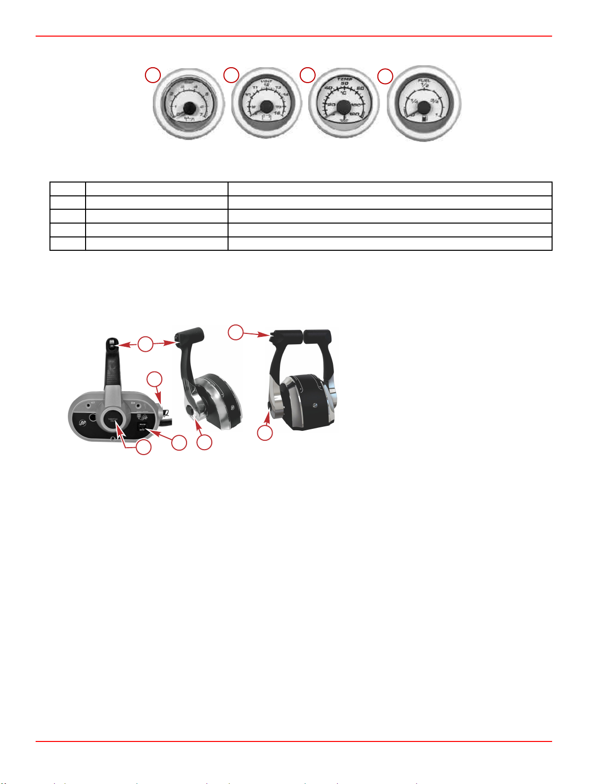
The following digital instruments may be included with your power package.
System Link digital gauges
Item Gauge Indicates
a Oil pressure gauge Engine oil pressure
b Voltmeter Battery voltage
c Water temperature gauge Engine operating temperature
d Fuel gauge Quantity of fuel in tank
Remote Controls (Non‑DTS Models)
Remote Control Features—Non‑DTS
Your boat may be equipped with one of the Mercury Precision or Quicksilver remote controls shown. If not, consult your dealer
for a description of the functions and operations of the remote control.
a - Trim/tilt switch
b - Ignition key switch—OFF, ON, START
c - Throttle only button
d - Lanyard stop switch
•
Trim/tilt switch ‑ Used to trim the drive during operation or raise the drive for trailering, launching, beaching, or shallow
water operation.
•
Throttle only button ‑ The throttle only button allows throttle advancement without shifting the engine. The throttle only
button disengages the shifting mechanism from the control handle. The throttle only button can be pressed and held in only
when the remote control handle is in the neutral position. While holding the throttle only button in, move the throttle handle
forward to assist in starting the engine.
•
Lanyard stop switch (if equipped) ‑ The purpose of a lanyard stop switch is to shut down the engine when the operator
moves far enough away from the operator's position to activate the switch. A lanyard stop switch can be installed as an
accessory, generally on the dashboard or side adjacent to the operator's position.
•
Control handle ‑ Operation of the shift and throttle is controlled by the movement of the control handle. Push the control
handle forward from neutral with a quick firm motion to the first detent for forward gear. Continue pushing forward to
increase speed. Pull the control handle back from neutral with a quick firm motion to the first detent for reverse gear.
Continue pulling back to increase speed.
IMPORTANT: Forcing the shift mechanism while the engine is not operating can result in product damage.
Gear Shifting
IMPORTANT: Observe the following:
•
Never shift the drive into gear unless the engine speed is at idle.
•
Do not shift the drive into reverse when the engine is not running.
• Your power package has three gear shift positions to provide operation: forward (F), neutral (N), and reverse (R).
• When shifting, always stop at the neutral position and allow the engine speed to return to idle.
• Always shift into gear with a quick motion.
Page 6 90-8M0128975 eng JUNE 2017
Page 15
Section 1 - Getting to Know Your Power Package
N
RF
58239
• After shifting into gear, advance the lever further to increase speed.
Remote Controls (DTS Models)
Remote Controls
IMPORTANT: Your boat must be equipped with a Mercury Marine electronic remote control. Start in gear protection is provided
by this control system and prevents the engine from starting when the control is actuated in forward or reverse. Refer to the
Mercury Precision Parts/Quicksilver Accessories Guide.
The digital throttle and shift (DTS) system required to operate this engine package provides start and stop functions, throttle
control, shift control, start in gear protection, and emergency lanyard stop functions. The DTS system works with specialized
helm components such as a command module kit and electronic remote control. Consult your dealer for a description and/or
demonstration of your remote control.
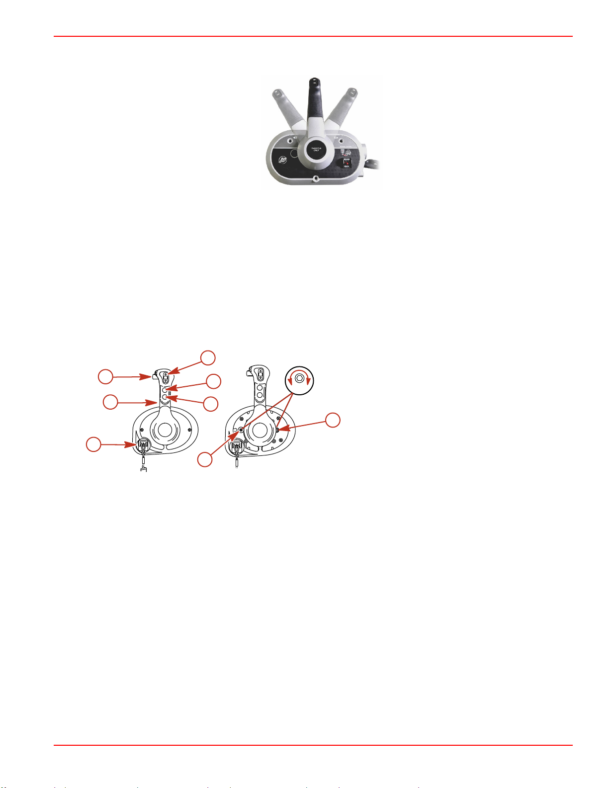
Panel Mount Features
d
c
b
e
-
+
f
a
g
Lanyard stop switch ‑ Turns the ignition off whenever the operator (when attached to the lanyard) moves far enough away
from the operator's position to activate the switch. Refer to Lanyard Stop Switch for information on the use of this switch.
Control handle ‑ Operation of the shift and throttle are controlled by the movement of the control handle. Push the control
handle forward from neutral with a quick, firm motion to the first detent for forward gear. Continue pushing forward to increase
speed. Pull the control handle back from neutral with a quick, firm motion to the first detent for reverse gear and continue
pushing back to increase speed.
Shift lock ‑ Pressing the shift lock allows the engine to shift. The shift lock must always be pressed when moving the control
handle out of the neutral position.
Trim/tilt switch (if equipped) ‑ Refer to Power Trim.
Throttle only button ‑ Allows engine throttle advancement without shifting the engine. The throttle only button can be
depressed only when the remote control is in the neutral position, and should only be used to assist in starting or warming up
the engine.
Start/stop button ‑ Allows the boat operator to start or stop the engine without using the ignition key.
Detent tension adjustment screw ‑ This screw can be adjusted to increase or decrease the effort required to move the control
handle out of the detent positions (cover must be removed). Turning the screw clockwise will increase tension.
Control handle friction adjustment screw ‑ This screw can be adjusted to increase or decrease the tension on the control
handle (cover must be removed). This will help prevent unwanted motion of the handle in rough water. Turn the screw
clockwise to increase tension and counterclockwise to decrease tension.
3409
a - Lanyard stop switch
b - Control handle
c - Shift lock
d - Trim/tilt switch
e - Throttle only button
h
f - Start/stop button
g - Detent tension adjustment screw
h - Control handle friction adjustment screw
90-8M0128975 eng JUNE 2017 Page 7
Page 16
Section 1 - Getting to Know Your Power Package
33173
F
R
a
b
e
c
d
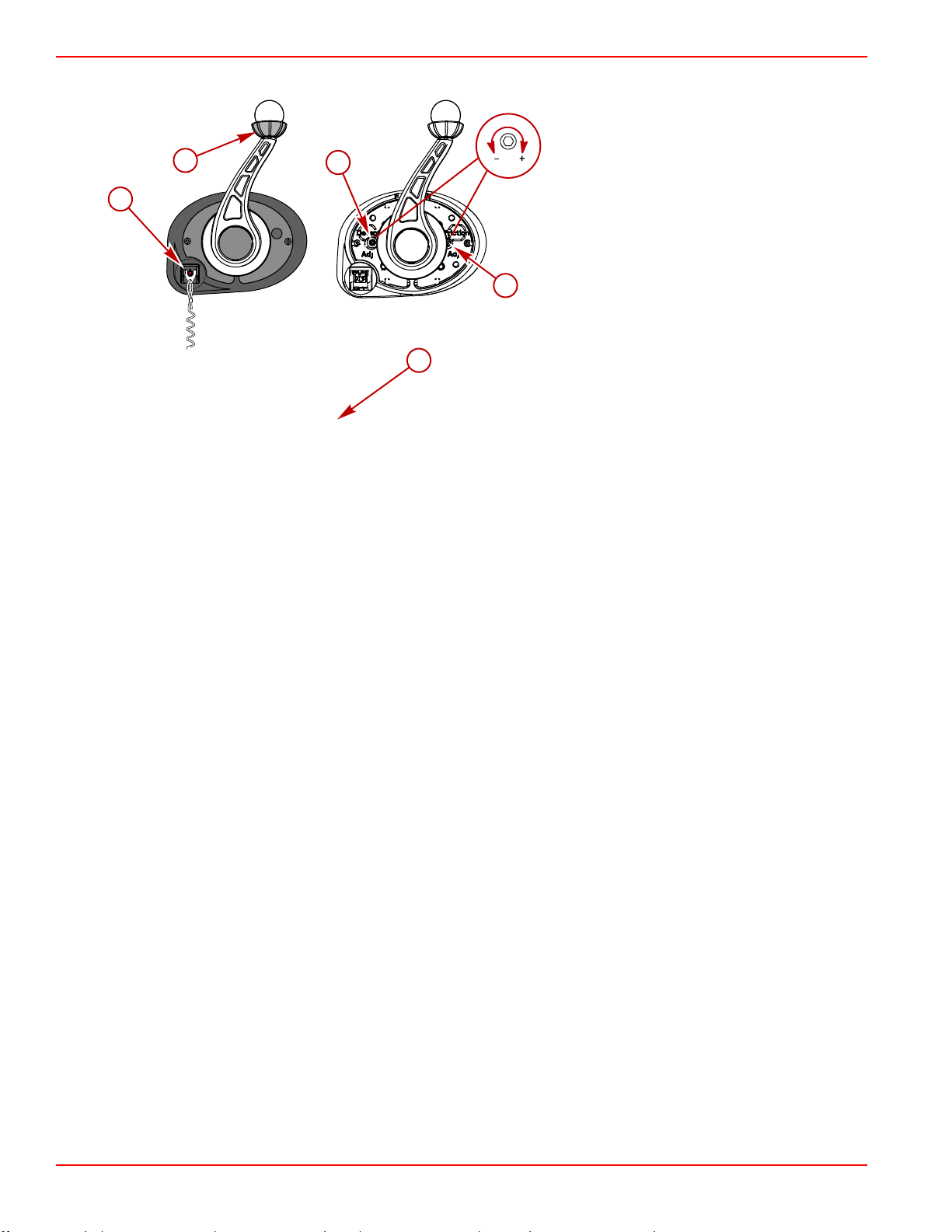
TowSports Panel Mount Features
a - Lanyard stop switch
b - Control handle and shift lock
c - Detent tension adjustment screw
d - Control handle tension adjustment screw
e - Throttle only button (on helm‑mounted CAN
pad)
Lanyard stop switch—The lanyard turns the ignition off whenever the operator moves far enough away from the operator's
position to activate the switch, assuming the operator is attached. Refer to Lanyard Stop Switch for more information.
Control handle—The control handle controls the shift and throttle. Push the control handle forward from neutral with a quick,
firm motion to the first detent for forward gear. Continue pushing forward to increase speed. Pull the control handle back from
neutral with a quick, firm motion to the first detent for reverse gear and continue pushing back to increase speed.
Shift lock—The shift lock allows the engine to shift. The shift lock must always be pressed when moving the control handle out
of the neutral position.
Throttle only button (optional)—The throttle only button allows engine throttle advancement without shifting the engine. The
throttle only button can be pressed only when the remote control is in the neutral position, and should only be used to assist in
starting or warming up the engine. The TowSport panel mount remote control may use an optional helm‑mounted CAN pad for
throttle only remote control operation. The hand throttle on and off switch kit with the foot throttle can also be used with the
TowSport panel mount control.
Throttle only operation—The throttle only operation allows engine throttle advancement without shifting the engine. Throttle
only operation is initiated when the ignition key switch is in the OFF position and the remote control is in the idle/forward
position. Refer to Throttle Only Operation—TowSport Panel Mount in Section 2. The throttle only feature should only be
used to assist in starting or warming up the engine.
Detent tension adjustment screw—Adjust this screw to increase or decrease the effort required to move the control handle
out of the detent positions. Remove the cover and turn the screw clockwise to increase tension.
Control handle tension adjustment screw—Adjust this screw to increase or decrease the tension on the control handle. This
reduces unwanted motion of the handle in rough water. Remove the cover and turn the screw clockwise to increase tension
and counterclockwise to decrease tension.
Electrical System Overload Protection
If an electrical system overload occurs, a fuse will fail or the circuit breaker will open. The cause must be found and corrected
before replacing the fuse or resetting the circuit breaker.
NOTE: In an emergency, when you must operate the engine and cannot locate the cause for the high current draw, turn off or
disconnect all accessories connected to the engine and instrumentation wiring. Reset the circuit breaker. If the breaker remains
open, the electrical overload has not been eliminated. Contact your authorized dealer.
Page 8 90-8M0128975 eng JUNE 2017
Page 17
Section 1 - Getting to Know Your Power Package
63785
63787
a
b
c
b
d
e
f
b
g
61447
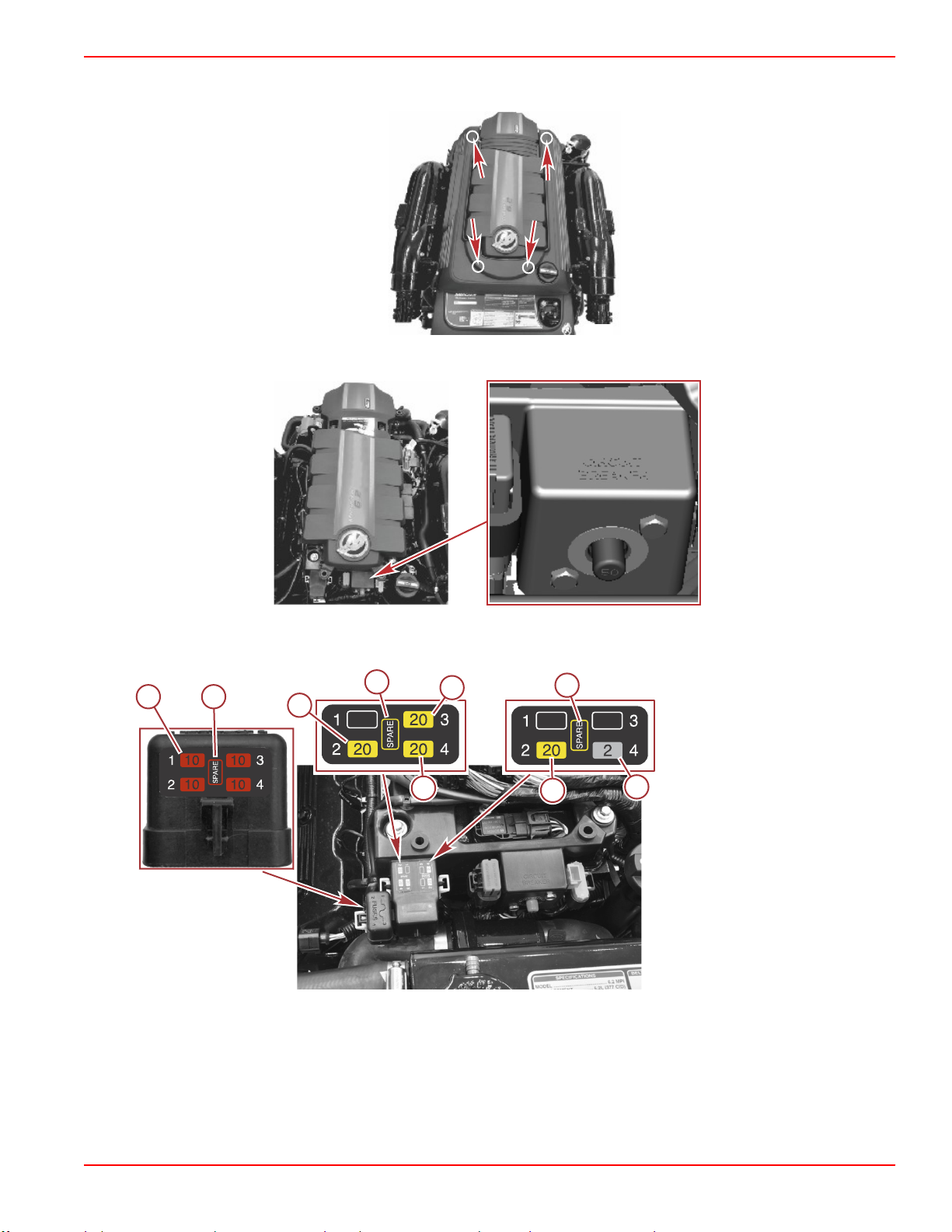
To access the circuit breaker and fuses, remove the outside engine cover. Pull the outside engine cover up to remove it from
the four rubber mount grommets.
The circuit breaker provides protection for the engine wiring harness and the instrumentation power lead.
All of the engine protection fuses are located at the front of the engine. To access the fuses, disengage the fuse holders from
the electrical plate assembly.
Mechanical engine, freshwater
cooled shown, others similar
a - Oxygen sensor fuses (4)
b - Spare fuses
c - Engine and trim relay fuse
d - Fuel injector fuse
e - Alternator and fuel pump relay
fuse
f - Ignition coil fuse
g - Malfunction indicator lamp
(MIL) fuse
90-8M0128975 eng JUNE 2017 Page 9
Page 18
Section 1 - Getting to Know Your Power Package
a
b
c
b
d
e
f
b
g
h
61448
a
b
56871
a
b
c
32206
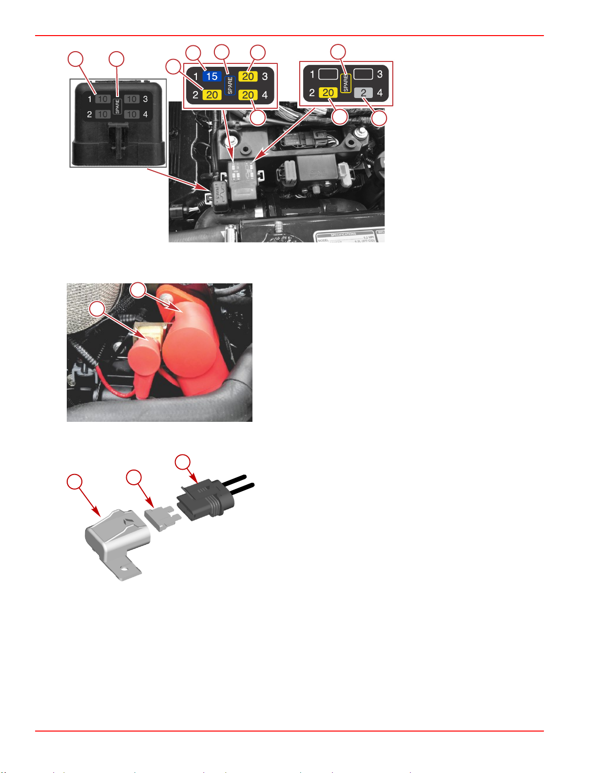
DTS engine, freshwater cooled
shown, others similar
a - Oxygen sensor fuses (4)
b - Spare fuses
c - Engine and trim relay fuse
d - DTS helm power fuse
e - Fuel injector fuse
f - Alternator and fuel pump relay
fuse
g - Ignition coil fuse
h - Malfunction indicator lamp
(MIL) fuse
A 90‑amp fuse located near the flame arrestor, protects the engine power harness if an electrical overload occurs. The fuse is
translucent so it can be inspected if the fuse has failed and is open.
a - 90‑amp fuse
b - Hot stud
A 15‑amp fuse located at the aft end of the engine, protects the accessory circuits.
a - Cover
b - 15‑amp fuse
c - Accessory harness
Page 10 90-8M0128975 eng JUNE 2017
Page 19
Section 1 - Getting to Know Your Power Package
47594
43608
a
b
c
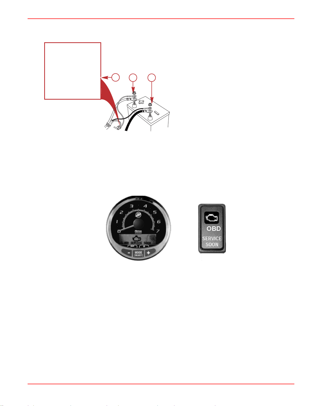
This power package uses a clean power harness that is connected to the engine starting battery. This clean power harness
minimizes an excessive voltage drop to the engine and drive digital control electrical system. This harness is protected by a
5‑amp fuse and is located near the engine starting battery.
a - 5‑amp fuse
b - Positive battery terminal (harness lead with fuse)
c - Negative battery terminal
Visual and Audio Warning Systems
Service Engine Light and OBD‑M MIL Kit
Boats powered by emissions control technology (ECT) catalyzed engines must be equipped with a SmartCraft‑enabled gauge
capable of displaying the service engine icon, or a dash‑mounted service engine light. Malfunction indicator lamp (MIL) kits
containing a dash‑mounted service engine light and a special harness that connects to the engine harness may be purchased
separately.
The service engine icon or MIL will provide a visual indication of a malfunction with the engine's emission control system and
will remain illuminated while the OBD‑M fault is active.
SC 1000 gauge and service engine light
Testing the OBD-M Malfunction Indicator Lamp (MIL)
1. Turn the ignition switch to the on position without cranking the engine.
2. The service engine icon and MIL will remain illuminated for four seconds if the visual indication system is functioning
correctly.
Audio Warning System
IMPORTANT: The audio warning system alerts the operator that a problem has occurred. It does not protect the engine from
damage.
Most faults cause the warning horn circuit to activate. How the warning horn activates depends on the severity of the problem.
There are two warning horn states:
• Caution
• Critical
There is also an alarm that sounds if the helm has not been properly configured using the G3 service tool.
90-8M0128975 eng JUNE 2017 Page 11
Page 20
Section 1 - Getting to Know Your Power Package
ON ON
OFF
ON
OFF
ON
OFF
ON
OFF
ON
OFF
1
1
1
1
1
1
1
1
1
1
1
OFF
33402
a
b
53403
a
b
ON
6
OFF
ON ON
OFF
ON
OFF
ON
OFF
ON
OFF
1
1
1
1
1
1
1
1
1
OFF
53402
a
b
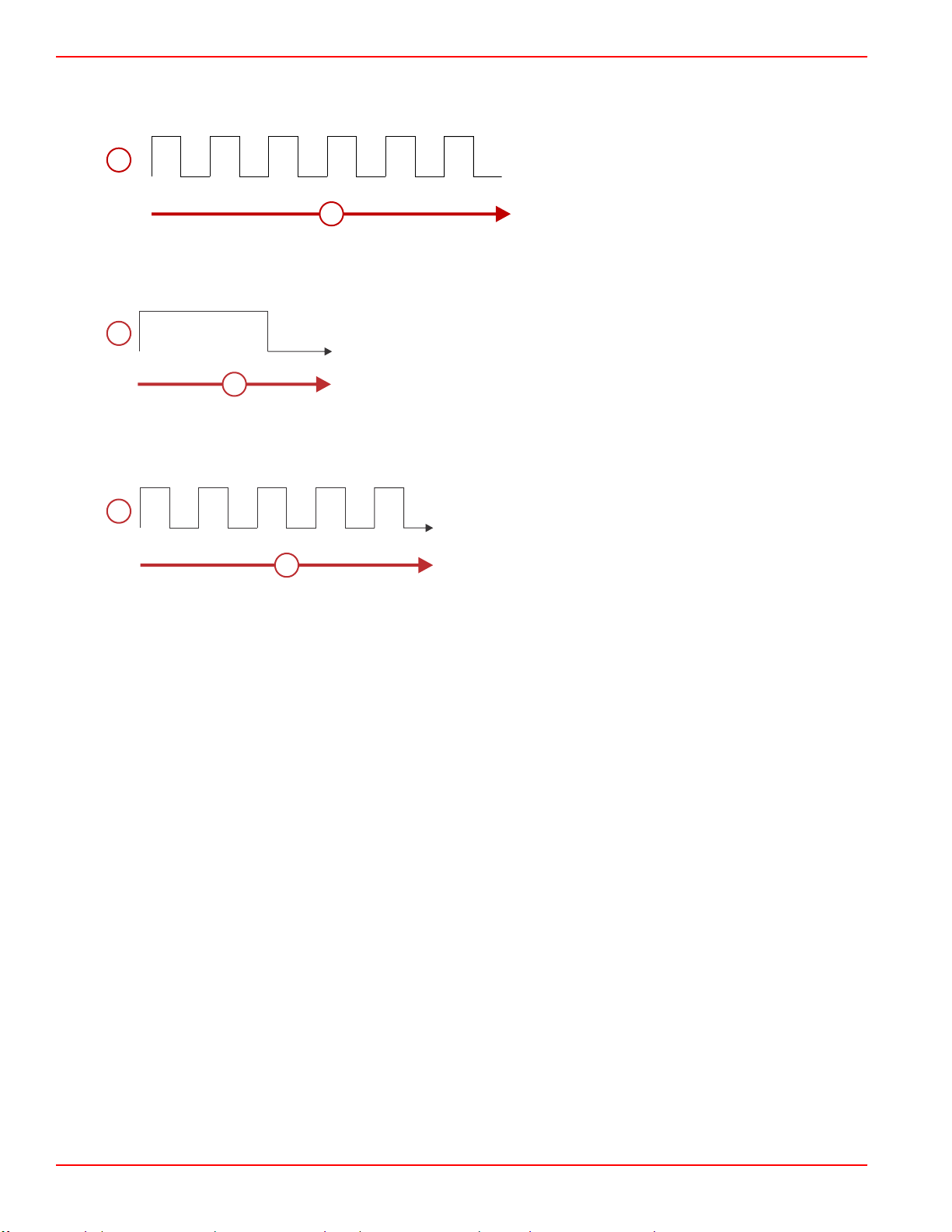
Caution
If a caution state is detected, the audio warning system will sound for six one‑second intervals.
a - Horn (on or off)
b - Time (in seconds)
Critical
If a critical state is detected, the audio warning system sounds for six seconds and then turns off.
a - Horn (on or off)
b - Time (in seconds)
Nonconfigured Alarm–DTS Only
If the helm has not been properly configured using the G3 service tool, the audio warning system will sound for five one‑second
intervals.
a - Horn (on or off)
b - Time (in seconds)
Testing the Audio Warning System
1. Turn the key switch to the on position without cranking the engine.
2. Listen for the audio alarm. The alarm will sound if the system is functioning correctly.
Guardian Strategy
The MerCruiser Engine Guardian system reduces the potential for engine damage by restricting engine power when the PCM
detects a potential problem. Below are some examples of what Engine Guardian monitors:
• Oil pressure
• Engine overspeed
• Exhaust manifold temperature
• Transmission oil temperature
IMPORTANT: Engine Guardian can reduce power anywhere from 100% to idle, depending on the severity of the problem. If
forced to idle, boat speed might not respond to throttle operation.
The PCM stores the fault for diagnostics. For example, if the water inlet becomes partially blocked, Engine Guardian reduces
the available power level of the engine to help prevent damage from decreased water flow to the engine. If the debris passes
through, and full water flow is restored, Engine Guardian restores engine power to normal.
Page 12 90-8M0128975 eng JUNE 2017
Page 21

Table of Contents
Section 2 - On the Water
Section 2 - On the Water
Safe Boating Recommendations.......................................... 14
Carbon Monoxide Exposure................................................. 15
Be Alert To Carbon Monoxide Poisoning ..................... 15
Stay Clear of Exhaust Areas ........................................ 15
Good Ventilation .......................................................... 15
Poor Ventilation ........................................................... 16
Basic Boat Operation ........................................................... 16
Launching and Boat Operation...................................... 16
Operation Chart ..................................................... 16
Starting and Stopping the Engine.................................. 16
Starting the Engine ................................................ 16
Stopping the Engine .............................................. 17
Throttle Only Operation—TowSport Panel Mount......... 17
Freezing Temperature Operation.................................. 18
Drain Plug and Bilge Pump............................................18
Protecting People in the Water............................................. 18
While You Are Cruising ................................................ 18
While Boat Is Stationary ............................................... 18
High‑Speed and High‑Performance Operation..................... 18
Passenger Safety in Pontoon Boats and Deck Boats.......... 18
Boats Having an Open Front Deck ............................... 19
Boats With Front‑Mounted, Raised Pedestal Fishing
Seats ............................................................................ 19
Wave and Wake Jumping..................................................... 19
Impact with Underwater Hazards......................................... 20
Conditions Affecting Operation............................................. 20
Weight Distribution (Passengers and Gear) Inside the
Boat............................................................................... 20
The Bottom of the Boat.................................................. 20
Cavitation....................................................................... 21
Ventilation...................................................................... 21
Elevation and Climate.................................................... 21
Getting Started..................................................................... 21
20‑Hour Break‑In Period................................................ 21
After the Break‑In Period............................................... 21
End of First Season Checkup........................................ 22
2
90-8M0128975 eng JUNE 2017 Page 13
Page 22

Section 2 - On the Water
Safe Boating Recommendations
To safely enjoy the waterways, familiarize yourself with local and all other governmental boating regulations and restrictions
and consider the following suggestions.
Know and obey all nautical rules and laws of the waterways.
• We recommend that all powerboat operators complete a boating safety course. In the U.S., the U.S. Coast Guard Auxiliary,
the Power Squadron, the Red Cross, and your state or provincial boating law enforcement agency provide courses. For
more information in the U.S., call the Boat U.S. Foundation at 1‑800‑336‑BOAT (2628).
Perform safety checks and required maintenance.
• Follow a regular schedule and ensure that all repairs are properly made.
Check safety equipment onboard.
• Here are some suggestions of the types of safety equipment to carry when boating:
Approved fire extinguishers
Signal devices: flashlight, rockets or flares, flag, and whistle or horn
Tools necessary for minor repairs
Anchor and extra anchor line
Manual bilge pump and extra drain plugs
Drinking water
Radio
Paddle or oar
Spare propeller, thrust hubs, and an appropriate wrench
First aid kit and instructions
Waterproof storage containers
Spare operating equipment, batteries, bulbs, and fuses
Compass and map or chart of the area
Personal flotation device (one per person onboard)
Watch for signs of weather change and avoid foul weather and rough‑sea boating.
Tell someone where you are going and when you expect to return.
Passenger boarding.
• Stop the engine whenever passengers are boarding, unloading, or are near the back (stern) of the boat. Shifting the drive
unit into neutral is not sufficient.
Use personal flotation devices.
• Federal law requires that there be a U.S. Coast Guard‑approved life jacket (personal flotation device), correctly sized and
readily accessible for every person onboard, plus a throwable cushion or ring. We strongly advise that everyone wear a life
jacket at all times while in the boat.
Prepare other boat operators.
• Instruct at least one person onboard in the basics of starting and operating the engine and boat handling in case the driver
becomes disabled or falls overboard.
Do not overload your boat.
• Most boats are rated and certified for maximum load (weight) capacities (refer to your boat's capacity plate). Know your
boat's operating and loading limitations. Know if your boat will float if it is full of water. When in doubt, contact your
authorized Mercury Marine dealer or the boat manufacturer.
Ensure that everyone in the boat is properly seated.
• Do not allow anyone to sit or ride on any part of the boat that was not intended for such use. This includes the backs of
seats, gunwales, transom, bow, decks, raised fishing seats, and any rotating fishing seat. Passengers should not sit or ride
anywhere that sudden unexpected acceleration, sudden stopping, unexpected loss of boat control, or sudden boat
movement could cause a person to be thrown overboard or into the boat. Ensure that all passengers have a proper seat
and are in it before any boat movement.
Never operate a boat while under the influence of alcohol or drugs. It is the law.
• Alcohol or drugs can impair your judgment and greatly reduce your ability to react quickly.
Know your boating area and avoid hazardous locations.
Page 14 90-8M0128975 eng JUNE 2017
Page 23
Section 2 - On the Water
41127
co
co
co
co
co
co
co
co
co
co
co
co
co
co
co
co
co
co
co
co
43367
Be alert.
• The operator of the boat is responsible by law to maintain a proper lookout by sight and hearing. The operator must have
an unobstructed view particularly to the front. No passengers, load, or fishing seats should block the operator's view when
the boat is above idle or planing transition speed. Watch out for others, the water, and your wake.
Never drive your boat directly behind a water skier.
• Your boat traveling at 40 km/h (25 mph) will overtake a fallen skier who is 61 m (200 ft) in front of you in five seconds.
Watch fallen skiers.
• When using your boat for waterskiing or similar activities, always keep a fallen or down skier on the operator's side of the
boat while returning to attend to the skier. The operator should always have the down skier in sight and never back up to
the skier or anyone in the water.
Report accidents.
• Boat operators are required by law to file a boating accident report with their state boating law enforcement agency when
their boat is involved in certain boating accidents. A boating accident must be reported if 1) there is loss of life or probable
loss of life, 2) there is personal injury requiring medical treatment beyond first aid, 3) there is damage to boats or other
property where the damage value exceeds $500.00, or 4) there is complete loss of the boat. Seek further assistance from
local law enforcement.
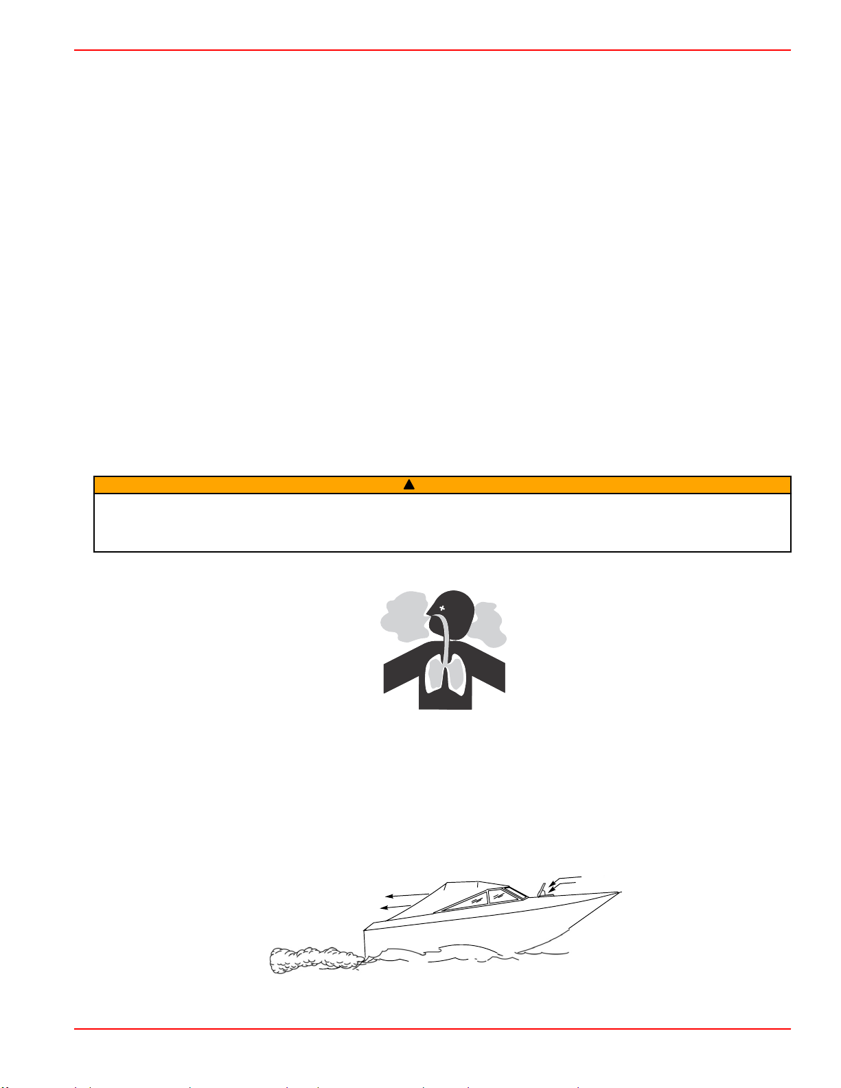
Carbon Monoxide Exposure
Be Alert To Carbon Monoxide Poisoning
Carbon monoxide (CO) is a deadly gas that is present in the exhaust fumes of all internal combustion engines, including the
engines that propel boats, and the generators that power boat accessories. By itself, CO is odorless, colorless, and tasteless,
but if you can smell or taste engine exhaust, you are inhaling CO.
Early symptoms of carbon monoxide poisoning, which are similar to the symptoms of seasickness and intoxication, include
headache, dizziness, drowsiness, and nausea.
WARNING
!
Inhaling engine exhaust gases can result in carbon monoxide poisoning, which can lead to unconsciousness, brain damage,
or death. Avoid exposure to carbon monoxide.
Stay clear from exhaust areas when engine is running. Keep the boat well‑ventilated while at rest or underway.
Stay Clear of Exhaust Areas
Engine exhaust gases contain harmful carbon monoxide. Avoid areas of concentrated engine exhaust gases. When engines
are running, keep swimmers away from the boat, and do not sit, lie, or stand on swim platforms or boarding ladders. While
underway, do not allow passengers to be positioned immediately behind the boat (platform dragging, teak/body surfing). This
dangerous practice not only places a person in an area of high engine exhaust concentration, but also subjects them to the
possibility of injury from the boat propeller.
Good Ventilation
Ventilate the passenger area, open side curtains or forward hatches to remove fumes.
Example of desired air flow through the boat:
90-8M0128975 eng JUNE 2017 Page 15
Page 24
Section 2 - On the Water
21626
a
b
a
b
43368
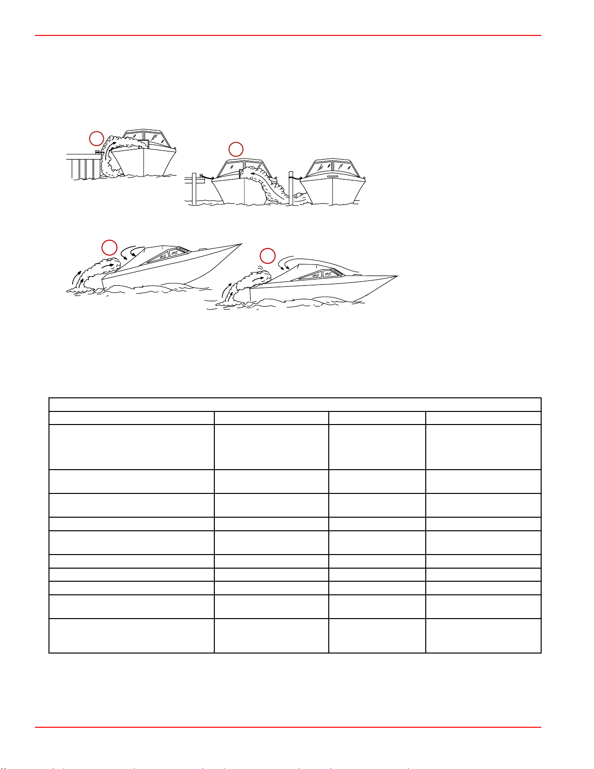
Poor Ventilation
Under certain running or wind conditions, permanently enclosed or canvas enclosed cabins or cockpits with insufficient
ventilation may draw in carbon monoxide. Install one or more carbon monoxide detectors in your boat.
Although the occurrence is rare, on a very calm day, swimmers and passengers in an open area of a stationary boat that
contains or is near a running engine may be exposed to a hazardous level of carbon monoxide.
1. Examples of poor ventilation while the boat is stationary:
a - Operating the engine when the boat
is moored in a confined space
b - Mooring close to another boat that
has its engine operating
2. Examples of poor ventilation while the boat is moving:
a - Operating the boat with the
trim angle of the bow too
high
b - Operating the boat with no
forward hatches open
(station wagon effect)
Basic Boat Operation
Launching and Boat Operation
IMPORTANT: Install bilge drain plug prior to launching boat.
Operation Chart
Operation Chart
BEFORE STARTING AFTER STARTING WHILE UNDERWAY AFTER STOPPING
Observe all gauges to
Install bilge drain plug.
Open engine hatch.
Turn battery switch on.
Operate bilge blowers. Check steering operation. Close seacock, if equipped.
Open fuel shut off valve.
Open seacock, if equipped. Drain bilge.
Close the drain system.
Check the engine oil.
Perform all other checks specified by
your dealer and/or boatbuilder.
Listen for audio warning alarm to sound
when the ignition switch is in the "ON"
position.
check condition of engine. If
not normal, stop engine.
Check for fuel, oil, water,
fluid and exhaust leaks.
Check shift and throttle
control operation.
Observe all gauges to
check condition of
engine. If not normal,
stop engine.
Listen for the audio
alarm.
Turn ignition key to the
"OFF" position.
Turn battery switch to the
"OFF" position.
Close fuel shut off valve.
Flush cooling system if in
saltwater.
Starting and Stopping the Engine
Starting the Engine
1.
Check all items listed in the Operation Chart.
Page 16 90-8M0128975 eng JUNE 2017
Page 25
Section 2 - On the Water
2. Place the remote control handle in neutral.
NOTICE
Without sufficient cooling water, the engine, the water pump, and other components will overheat and suffer damage. Provide
a sufficient supply of water to the water inlets during operation.
WARNING
!
Explosive fumes contained in the engine compartment can cause serious injury or death from fire or explosion. Before
starting the engine, operate the bilge blower or vent the engine compartment for at least five minutes.
NOTE: This power package is equipped with SmartStart. The SmartStart feature incorporates push button starting. Rather
than holding the start button or key switch to start the engine and then releasing it when the engine starts, SmartStart
completely controls the starting process. When the start button is pushed, the PCM signals the engine to start. If the
engine does not start, the starting process times out after a few seconds or when the engine reaches 400 RPM. Attempting
to start the engine with the engine already running will turn the engine off.
3. Turn the ignition key to the RUN position.
4. Turn the ignition key switch to the START position then release, or press the start/stop button and release. If the engine is
cold, allow the engine to operate at idle for 6–10 minutes or until the engine temperature reaches 60° C (140° F).
5. If the engine does not start after three attempts:
a. Push the throttle only button and position the remote control handle or throttle lever to the 1/4 throttle position.
b. Turn the ignition key to START. Release the key when the engine starts and allow the switch to return to the ON
position.
6. If the engine does not start after step 5:
a. Move the remote control handle throttle lever to the full throttle position, then return to 1/4 throttle.
b. Turn the ignition key to START. Release the key when the engine starts and allow the switch to return to the ON
position.
7. Inspect the power package for fuel, oil, water, and exhaust leaks.
8. Move the control handle with a firm, quick motion forward to shift to forward gear, or backward to shift to reverse. After
shifting, advance the throttle to the desired setting.
NOTICE
Shifting into gear at engine speeds above idle will damage the drive system. Shift the drive into gear only when the engine is
operating at idle.
Stopping the Engine
1. Move the remote control handle to neutral/idle and allow the engine to slow to idle speed. If the engine has been operated
at high speed for a long period of time, allow the engine to cool at idle speed for 3–5 minutes.
2. The engine can be stopped by any one of the following four methods:
a. Move the ignition key switch to the ACCESSORY or OFF position. The engine will stop and the control system will be
deactivated.
b. Press the start/stop button, if equipped. The engine will stop and the control system will remain active.
c. Momentarily move the ignition key switch to the START position, then release immediately. The control system will
recognize that the engine is running and will stop the engine. The control system will remain active. Moving the
ignition key switch to the START position again will issue a start request to the control system and the control system
will start the engine, if appropriate.
d. Activate the lanyard stop switch, if equipped. The engine will stop, but the control system will remain active. The
control system will not allow the engine to start if the lanyard stop switch is activated.
Throttle Only Operation—TowSport Panel Mount
NOTE: When operating in throttle only (neutral) mode, the DTS control system will not allow the engine speed to increase
above 3500 RPM.
WARNING
!
The Digital Throttle and Shift (DTS) Zero Effort control can shift the engine or transmission at speeds greater than idle,
causing unexpected boat movement, which may result in injury, death, or property damage due to loss of boat control.
Always place the throttle control lever in the idle position before moving the shift control lever into forward or reverse gear
position.
90-8M0128975 eng JUNE 2017 Page 17
Page 26
Section 2 - On the Water
21604
TowSport Panel‑Mount Remote Controls: TowSport panel‑mount remote controls are not equipped with a throttle only
button. To activate throttle only mode:
1.
Refer to Remote Controls section for remote control features.
2. Move the ignition key switch to the "OFF" position.
3. Move the control lever to the idle‑forward position.
4. Start the engine.
5. Advancing the control lever beyond the idle‑forward position will cause engine speed to increase.
IMPORTANT: Moving the control lever back to the idle‑neutral position will deactivate the throttle only mode and allow the
engine to shift into gear.
6. Deactivate throttle only mode by moving the control lever to the idle‑neutral position. Moving the control lever from the
idle‑neutral position to the idle‑forward or idle‑reverse position without repeating steps 1. through 4. will shift the unit into
the chosen gear.
Freezing Temperature Operation
IMPORTANT: If the boat is operated during periods of freezing temperature, precautions must be taken to prevent freeze
damage to the power package. Damage caused by freezing is not covered by Mercury MerCruiser Limited Warranty.
Drain Plug and Bilge Pump
The engine compartment in your boat is a natural place for water to collect. For this reason, boats are normally equipped with a
drain plug and/or a bilge pump. It is very important to check these items on a regular basis to ensure that the water level does
not come into contact with your power package. Components on your engine will be damaged if submerged. Damage caused
by submersion is not covered by the Mercury MerCruiser Limited Warranty.
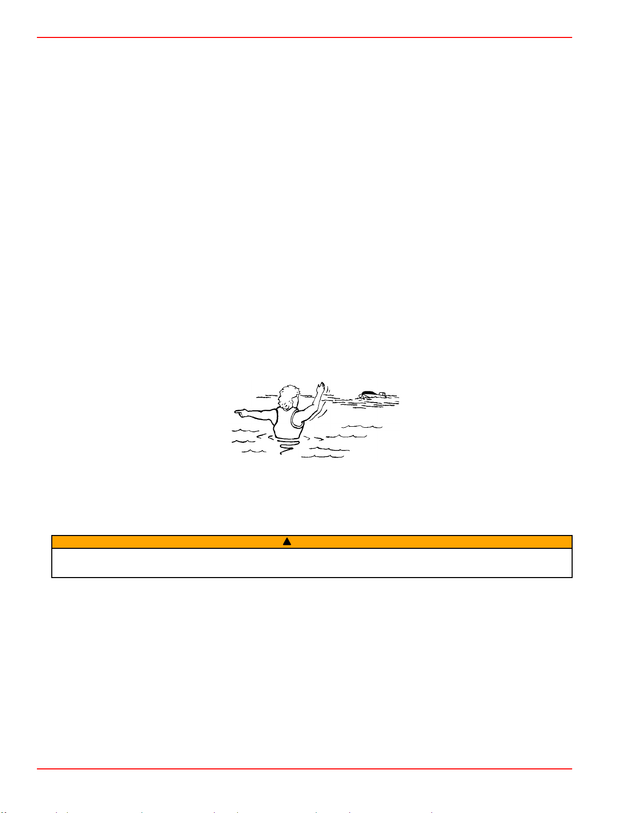
Protecting People in the Water
While You Are Cruising
It is very difficult for a person in the water to take quick action to avoid a boat heading in their direction, even at slow speeds.
Always slow down and exercise extreme caution any time you are boating in an area where there might be people in the water.
Whenever a boat is moving (even coasting) and the gear shift is in neutral, there is sufficient force by the water on the propeller
to cause the propeller to rotate. This neutral propeller rotation can cause serious injury.
While Boat Is Stationary
WARNING
!
A spinning propeller, a moving boat, or any solid device attached to the boat can cause serious injury or death to swimmers.
Stop the engine immediately whenever anyone in the water is near your boat.
Shift into neutral and shut off the engine before allowing people to swim or be in the water near your boat.
High‑Speed and High‑Performance Operation
If your boat is considered a high‑speed or high‑performance boat and you are unfamiliar with its operation, we recommend that
you never operate it at its high speed capability without first requesting an initial orientation and demonstration ride with your
dealer or an operator experienced with your boat. For additional information, refer to Hi‑Performance Boat Operation booklet
(90‑849250R03) from your dealer, distributor, or Mercury Marine.
Passenger Safety in Pontoon Boats and Deck Boats
Whenever the boat is in motion, observe the location of all passengers. Do not allow any passengers to stand or use seats
other than those designated for traveling faster than idle speed. A sudden reduction in boat speed, such as plunging into a
large wave or wake, a sudden throttle reduction, or a sharp change of boat direction, could throw them over the front of the
boat. Falling over the front of the boat between the two pontoons will position them to be run over.
Page 18 90-8M0128975 eng JUNE 2017
Page 27
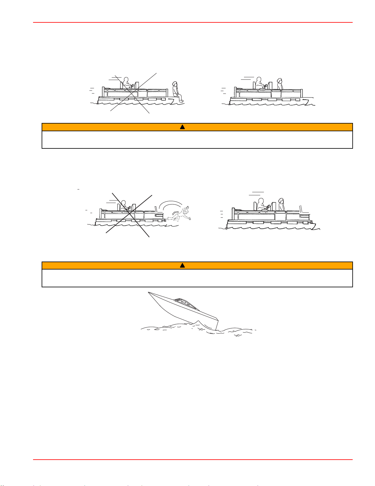
Section 2 - On the Water
Boats Having an Open Front Deck
No one should ever be on the deck in front of the fence while the boat is in motion. Keep all passengers behind the front fence
or enclosure.
Persons on the front deck could easily be thrown overboard or persons dangling their feet over the front edge could get their
legs caught by a wave and pulled into the water.
mc79555-1
WARNING
!
Sitting or standing in an area of the boat not designed for passengers at speeds above idle can cause serious injury or death.
Stay back from the front end of deck boats or raised platforms and remain seated while the boat is in motion.
Boats With Front‑Mounted, Raised Pedestal Fishing Seats
Elevated fishing seats are not intended for use when the boat is traveling faster than idle or trolling speed. Sit only in seats
designated for traveling at faster speeds.
Any unexpected, sudden reduction in boat speed could result in the elevated passenger falling over the front of the boat.
mc79557-1
Wave and Wake Jumping
WARNING
!
Wave or wake jumping can cause serious injury or death from occupants being thrown within or out of the boat. Avoid wave
or wake jumping whenever possible.
mc79680-1
Operating recreational boats over waves and wakes is a natural part of boating. However, when this activity is done with
enough speed to force the boat hull partially or completely out of the water, certain hazards arise, particularly when the boat
reenters the water.
The primary concern is the boat changing direction while in the midst of the jump. In such cases the landing may cause the
boat to violently veer in a new direction. Such a sharp change in direction or turn can cause occupants to be thrown out of their
seats or out of the boat.
There is another less common hazardous result from allowing your boat to launch off of a wave or wake. If the bow of your boat
pitches down far enough while airborne, upon water contact it may penetrate under the water surface and submarine for an
instant. This will bring the boat nearly to a stop in an instant and can send the occupants flying forward. The boat may also veer
sharply to one side.
90-8M0128975 eng JUNE 2017 Page 19
Page 28

Section 2 - On the Water
Impact with Underwater Hazards
Reduce speed and proceed with caution whenever you're driving a boat in shallow water or in areas where the waters are
suspected of having underwater obstacles that could be struck by the underwater drive components, rudder, or the boat
bottom.
7576
IMPORTANT: The most important thing you can do to help reduce injury or impact damage from striking a floating or
underwater object is control the boat speed. Under these conditions, boat speed should be kept to the minimum planing speed,
typically 24–40 km/h (15–25 mph).
WARNING
!
Avoid serious injury or death from all or part of an outboard or drive unit coming into the boat after striking a floating or
underwater object. When operating in waters where objects may be at the surface or just under the surface of the water,
reduce your speed and keep a vigilant lookout.
Examples of objects that can cause engine damage are dredging pipes, bridge supports, wing dams, trees, stumps, and
rocks.
Striking a floating or underwater object could result in any of an infinite number of situations. Some of these situations could
yield the following:
• The boat could move suddenly in a new direction. A sharp change in direction can cause occupants to be thrown out of
their seats or out of the boat.
• The boat's speed could rapidly reduce. This will cause occupants to be thrown forward or even out of the boat.
• The underwater drive components, rudder, or boat could sustain impact damage.
After striking a submerged object, stop the engine as soon as possible and inspect the drive system for any broken or loose
parts. If damage is present or suspected, the power package should be taken to an authorized Mercury MerCruiser dealer for a
thorough inspection and necessary repair.
The boat should also be checked for any hull fractures, transom fractures, or water leaks. If water leaks are discovered after an
impact, immediately activate the bilge pump.
Operating with damaged underwater drive components, rudder, or boat bottom could cause additional damage to other parts of
the power package or could affect control of the boat. If continued operation is necessary, do so at greatly reduced speeds.
WARNING
!
Operating a boat or engine with impact damage can result in product damage, serious injury, or death. If the vessel
experiences any form of impact, have an authorized Mercury Marine dealer inspect and repair the vessel or power package.
Conditions Affecting Operation
Weight Distribution (Passengers and Gear) Inside the Boat
Shifting weight to rear (stern):
• Generally increases speed and engine RPM
• Causes bow to bounce in choppy water
• Increases danger of following wave splashing into the boat when coming off plane
• At extremes, can cause the boat to porpoise
Shifting weight to front (bow):
• Improves ease of planing
• Improves rough water ride
• At extremes, can cause the boat to veer back and forth (bow steer)
The Bottom of the Boat
To maintain maximum speed, the boat bottom should be:
Page 20 90-8M0128975 eng JUNE 2017
Page 29

Section 2 - On the Water
• Clean, free of barnacles and marine growth
• Free of distortion; nearly flat where it contacts the water
• Straight and smooth, fore and aft
Marine vegetation may accumulate when the boat is docked. This growth must be removed before operation; it may clog the
water inlets and cause the engine to overheat.
Cavitation
Cavitation occurs when water flow cannot follow the contour of a fast‑moving underwater object, such as a gear housing or a
propeller. Cavitation increases propeller speed while reducing boat speed. Cavitation can seriously erode the surface of the
gear housing or the propeller. Common causes of cavitation are:
• Weeds or other debris snagged on the propeller
• Bent propeller blade
• Raised burrs or sharp edges on the propeller
Ventilation
Ventilation is caused by surface air or exhaust gases that are introduced around the propeller resulting in propeller speed‑up
and a reduction in boat speed. Air bubbles strike the propeller blade and cause erosion of the blade surface. If allowed to
continue, eventual blade failure (breakage) will occur. Excessive ventilation is usually caused by:
• Drive unit trimmed out too far
• A missing propeller diffuser ring
• A damaged propeller or gear housing, which allows exhaust gases to escape between propeller and gear housing
• Drive unit installed too high on transom
Elevation and Climate
Elevation and climate changes will affect the performance of your power package. Loss of performance can be caused by:
• Higher elevations
• Higher temperatures
• Low barometric pressures
• High humidity
For you to have optimum engine performance under changing weather conditions, it is essential that the engine be propped to
allow the engine to operate at or near the top end of the specified maximum RPM range with a normal boat load during your
normal boating weather conditions.
In most cases, recommended RPM can be achieved by changing to a lower pitch propeller.
Getting Started
20‑Hour Break‑In Period
IMPORTANT: The first 20 hours of operation is the engine break‑in period. Correct break‑in is essential to obtain minimum oil
consumption and maximum engine performance. During this break‑in period, the following rules must be observed:
• Do not operate below 1500 RPM for extended periods of time for the first 10 hours. Shift into gear as soon as possible after
starting and advance the throttle above 1500 RPM if conditions permit safe operation.
• Do not operate at one speed consistently for extended periods.
• Do not exceed 3/4 throttle during the first 10 hours. During the next 10 hours, occasional operation at full throttle is
permissible (five minutes at a time maximum).
• Avoid full throttle acceleration from idle speed.
• Do not operate at full throttle until the engine reaches normal operating temperature.
• Frequently check engine oil level. Add oil as needed. It is normal for oil consumption to be high during the break‑in period.
After the Break‑In Period
To help extend the life of your Mercury MerCruiser power package, follow these recommendations:
• Ensure that the propeller allows the engine to operate at or near the top of the specified wide‑open throttle (WOT) RPM
range. Refer to Specifications and Maintenance.
• Operate the engine at 3/4 throttle or lower. Refrain from prolonged operation at WOT RPM.
• At 25 hours of operation, change the transmission fluid. Models equipped with a transmission filter must also have the filter
changed at this time.
90-8M0128975 eng JUNE 2017 Page 21
Page 30

Section 2 - On the Water
End of First Season Checkup
At the end of the first season of operation, contact an authorized Mercury MerCruiser dealer to discuss and/or perform
scheduled maintenance items. If you are in an area where the product is operated continuously, year‑round, you should contact
your dealer at the end of the first 100 hours of operation or once yearly, whichever occurs first.
Page 22 90-8M0128975 eng JUNE 2017
Page 31

Table of Contents
Section 3 - Specifications
Section 3 - Specifications
Fuel Requirements............................................................... 24
Fuel Ratings ................................................................. 24
Using Reformulated (Oxygenated) Gasoline (USA Only)
...................................................................................... 24
Gasoline Containing Alcohol ........................................ 24
Bu16 Butanol Fuel Blends ..................................... 24
Methanol and Ethanol Fuel Blends ....................... 24
Engine Oil............................................................................. 24
6.2 MPI TowSport Engine Specifications............................. 25
Fluid Specifications............................................................... 26
Engine............................................................................26
Transmission................................................................. 26
3
90-8M0128975 eng JUNE 2017 Page 23
Page 32

Section 3 - Specifications
Fuel Requirements
NOTICE
Running out of fuel can damage catalyst components. Do not allow the fuel tanks to become empty during operation.
IMPORTANT: Use of improper gasoline can damage your engine. Engine damage resulting from the use of improper
gasoline is considered misuse of the engine and will not be covered under the limited warranty.
Fuel Ratings
Mercury MerCruiser engines will operate satisfactorily with any major brand of unleaded gasoline that meets the following
specifications:
USA and Canada ‑ A posted pump octane rating of 87 (R+M)/2, minimum, for all models. Premium gasoline 91 (R+M)/2
octane is also acceptable for all models. Do not use leaded gasoline.
Outside USA and Canada ‑ A posted pump octane rating of 91 RON, minimum, for all models. Premium gasoline (95 RON) is
also acceptable for all models. Do not use leaded gasoline.
Using Reformulated (Oxygenated) Gasoline (USA Only)
Reformulated gasoline is required in certain areas of the USA and is acceptable for use in your Mercury Marine engine. The
only oxygenate currently in use in the USA is alcohol (ethanol, methanol, or butanol).
Gasoline Containing Alcohol
Bu16 Butanol Fuel Blends
Fuel blends of up to 16.1% butanol (Bu16) that meet the published Mercury Marine fuel rating requirements are an acceptable
substitute for unleaded gasoline. Contact your boat manufacturer for specific recommendations on your boat's fuel system
components (fuel tanks, fuel lines, and fittings).
Methanol and Ethanol Fuel Blends
IMPORTANT: The fuel system components on your Mercury Marine engine will withstand up to 10% alcohol (methanol or
ethanol) content in the gasoline. Your boat's fuel system may not be capable of withstanding the same percentage of alcohol.
Contact your boat manufacturer for specific recommendations on your boat's fuel system components (fuel tanks, fuel lines,
and fittings).
Be aware that gasoline containing methanol or ethanol may cause increased:
• Corrosion of metal parts
• Deterioration of rubber or plastic parts
• Fuel permeation through the rubber fuel lines
• Likelihood of phase separation (water and alcohol separating from the gasoline in the fuel tank)
WARNING
!
Fuel leakage is a fire or explosion hazard, which can cause serious injury or death. Periodically inspect all fuel system
components for leaks, softening, hardening, swelling, or corrosion, particularly after storage. Any sign of leakage or
deterioration requires replacement before further engine operation.
IMPORTANT: If you use gasoline that contains or might contain methanol or ethanol, you must increase the frequency of
inspection for leaks and abnormalities.
IMPORTANT: When operating a Mercury Marine engine on gasoline containing methanol or ethanol, do not store the gasoline
in the fuel tank for long periods. Cars normally consume these blended fuels before they can absorb enough moisture to cause
trouble; boats often sit idle long enough for phase separation to take place. Internal corrosion may occur during storage if
alcohol has washed protective oil films from internal components.
Engine Oil
For optimum engine performance and maximum protection, use the following oil:
Application
All MerCruiser engines Mercury/Quicksilver 25W‑40 Synthetic Blend Engine Oil, NMMA FC‑W Catalyst Compatible rated
IMPORTANT: Lubrication requirements for catalyzed engines differ from the requirements for noncatalyzed engines. Some
marine‑grade lubricants contain high levels of phosphorus. Although these high‑phosphorus lubricants may allow acceptable
engine performance, exposure over time will damage the catalyst. Catalysts damaged by lubricants containing high levels of
phosphorus may not be covered by the MerCruiser Limited Warranty.
Page 24 90-8M0128975 eng JUNE 2017
Recommended Oil
Page 33

Section 3 - Specifications
Mercury/Quicksilver 25W-40 Synthetic Blend, NMMA FC-W Catalyst Compatible rated 4-cycle oil
Other recognized brands of NMMA FC-W Catalyst Compatible rated 4-cycle oil
SAE 20W
SAE30W
SAE40W
AIR TEMPERATURE
ORDER OF PREFERENCE
(32° F)
0° C
(50° F)
10° C
Mercury/Quicksilver 25W-40 Mineral NMMA FC-W Catalyst Compatible rated 4-cycle oil
53574
Other recognized brands of NMMA FC-W rated 4-cycle oil
If Mercury/Quicksilver 25W‑40 Synthetic Blend Engine Oil is unavailable, use the following lubricants, listed in order of
recommendation.
1. Mercury/Quicksilver 25W‑40 Mineral NMMA FC‑W Catalyst Compatible.
IMPORTANT: If you are servicing a catalyst engine, use the following oils for short periods of time only.
2. Other recognized brands of NMMA FC‑W Catalyst Compatible rated 4‑cycle oil.
3. Other recognized brands of NMMA FC‑W rated 4‑cycle oils.
4. A good‑grade, straight‑weight detergent automotive oil according to the last row of the operating chart below.
NOTE: We do not recommend nondetergent oils, multi‑viscosity oils (other than as specified), non‑FC‑W rated synthetic oils,
low‑quality oils, or oils that contain solid additives.
Use the following information for selecting the type of oil according to the order of preference.
6.2 MPI TowSport Engine Specifications
NOTE: Performance specifications are obtained and corrected in accordance with SAE J1228/ISO 8665 Crankshaft Power.
All measurements are taken with the engine at normal operating temperature.
RPM range is measured using an accurate service tachometer with the engine at normal operating temperatures.
Oil pressure must be checked with the engine at normal operating temperature.
NOTE: Oil pressure specifications are for reference and may vary.
IMPORTANT: Do not mix spark plug types in an engine. All spark plugs should have the same part number.
90-8M0128975 eng JUNE 2017 Page 25
Page 34

Section 3 - Specifications
Crankshaft power
Displacement
Alternator amperage
RPM
Minimum oil pressure
Thermostat
Firing order
Minimum battery rating*
Spark plug type
Spark plug gap
Emission control system
*Battery manufacturers may rate and test their batteries to different standards. MCA, CCA, Ah, and reserve capacity (RC) are
the ratings recognized by Mercury Marine. Manufacturers that use standards different than these, such as equivalent MCA, do
not meet Mercury Marine battery requirements.
Hot 72 A
Cold 65 A
WOT operating range 5000–5400
Rev limiter 5550
Idle in neutral 625 (not adjustable)
Idle in gear 650 (not adjustable)
At 2000 RPM 124 kPa (18 psi)
At idle 41 kPa (6 psi)
Standard cooling 60 °C (140 °F)
Closed cooling 77 °C (170 °F)
All models 800 CCA, 1000 MCA, 190 Ah
Factory installed NGK (BPR5EFS‑13)
ECT
EC Electronic engine control
heated oxygen sensor (HO2S), catalyst
235 kW (320 hp)
272 kW (370 hp)
6.2 L (377 cid)
1‑8‑4‑3‑6‑5‑7‑2
1.3 mm (0.051 in.)
Emission control technology,
Fluid Specifications
Engine
IMPORTANT: Always use the dipstick to determine the exact quantity of oil or fluid required.
All Models
6.2L engine oil (with filter) 4.7 L (5 US qt)
6.2L seawater cooling system
(winterization use only)
6.2L closed‑cooling system 17 L (17.9 US qt)
Transmission
Model
45C 2.5 L (2.6 US qt)
45IV and 46IV
63IV V‑drive 4.4 L (4.6 US qt)
Main transmission 2.5 L (2.6 US qt)
V‑drive 1.0 L (1.0 US qt)
Capacity Fluid Type
Mercury/Quicksilver 25W‑40 Synthetic Blend Engine Oil, NMMA
26.5 L (28 US qt) Propylene glycol and purified water
Mercury Extended Life Coolant Antifreeze or extended‑life
ethylene glycol 5/100 antifreeze mixed 50/50 with purified water
Capacity Fluid Type
FC‑W®
Dexron III Automatic
Transmission Fluid
Page 26 90-8M0128975 eng JUNE 2017
Page 35

Table of Contents
Section 4 - Maintenance
Section 4 - Maintenance
Owner/Operator Responsibilities.......................................... 28
Dealer Responsibilities......................................................... 28
Cleaning Care Recommendation......................................... 28
Cleaning Gauges........................................................... 28
Cleaning Remote Controls.............................................28
Maintenance......................................................................... 28
Do‑It‑Yourself Maintenance Suggestions............................. 29
Inspection............................................................................. 29
MerCruiser Gas Inboard Inspection and Maintenance
Schedule............................................................................... 29
Daily Checks ................................................................. 29
After Each Use ............................................................. 29
Weekly Checks ............................................................. 29
20 Hour Break In .......................................................... 30
Annually or 100 Hours .................................................. 30
Three Years or 300 Hours ............................................ 30
Five Years or 500 Hours ............................................... 30
Engine Oil............................................................................. 30
Checking........................................................................ 30
Oil Level—Overfilled .............................................. 31
Filling............................................................................. 31
Engine Oil Drain Pump.................................................. 32
Changing the Oil Filter................................................... 33
Engine Coolant ‑ Closed‑Cooling......................................... 33
Checking........................................................................ 33
Filling............................................................................. 34
Changing ...................................................................... 35
Transmission Fluid............................................................... 35
Checking the Fluid Level Before Operation .................. 35
Checking the Fluid Level When Hot ............................. 36
Changing ...................................................................... 36
Transmission Anodes—45IV and 46IV................................. 36
Transmission Remote Control Cable Adjustment ................ 37
Battery.................................................................................. 37
Multiple EFI Engine Battery Precautions....................... 37
Flame Arrestor...................................................................... 38
Fuel System Maintenance.................................................... 40
Fuel System................................................................... 40
Fuel Line Inspection.......................................................40
Water‑Separating Fuel Filter..........................................40
Filter Housing Removal ......................................... 40
Draining the Filter Housing .................................... 41
Fuel Filter Inspection ............................................. 41
Filter Housing Installation ...................................... 41
Lubrication............................................................................ 42
Transmission Linkage.................................................... 42
Serpentine Drive Belt............................................................ 42
Serpentine Drive Belt Routing....................................... 42
Serpentine Belt Failure Identification............................. 43
Checking........................................................................ 44
Replacing....................................................................... 44
Flushing the Power Package—Models without a Flushing
Attachment .......................................................................... 45
The Boat Out of the Water ............................................ 45
The Boat in the Water ................................................... 47
Flushing the Power Package—Models with a Flushing
Attachment .......................................................................... 48
4
90-8M0128975 eng JUNE 2017 Page 27
Page 36

Section 4 - Maintenance
Owner/Operator Responsibilities
It is the operator's responsibility to perform all safety checks, to ensure that all lubrication and maintenance instructions are
complied with for safe operation and to return the unit to an authorized Mercury MerCruiser dealer for a periodic checkup.
Normal maintenance service and replacement parts are the responsibility of the owner/operator and as such, are not
considered defects in workmanship or material within the terms of the warranty. Individual operating habits and usage
contribute to the need for maintenance service.
Proper maintenance and care of your power package will ensure optimum performance and dependability and will keep your
overall operating expenses at a minimum. See your authorized Mercury MerCruiser dealer for service aids.
Dealer Responsibilities
In general, a dealer's responsibilities to the customer include predelivery inspection and preparation such as:
• Ensure that the boat is properly equipped.
• Prior to delivery, make certain that the Mercury MerCruiser power package and other equipment are in proper operating
condition.
• Make all necessary adjustments for maximum efficiency.
• Familiarize the customer with the onboard equipment.
• Explain and demonstrate the operation of the power package and boat.
• Provide you with a copy of a Predelivery Inspection Checklist.
• Your selling dealer should fill out the Warranty Registration Card completely and mail it to the factory immediately upon
sale of the new product.
Cleaning Care Recommendation
Cleaning Gauges
IMPORTANT: Never use high‑pressure water to clean gauges.
Routine cleaning of the gauges is recommended to prevent a buildup of salt and other environmental debris. Crystalized salt
can scratch the gauge display lens when using a dry or damp cloth. Ensure that the cloth has a sufficient amount of fresh water
to dissolve and remove salt or mineral deposits. Do not apply aggressive pressure on the display lens while cleaning.
When water marks cannot be removed with a damp cloth, mix a 50/50 solution of warm water and isopropyl alcohol to clean the
display lens. Do not use acetone, mineral spirits, turpentine type solvents, or ammonia based cleaning products. The use of
strong solvents or detergents may damage the coating, the plastics, or the rubber keys on the gauges. If the gauge has a sun
cover available, it is recommended that the cover be installed when the unit is not in use to prevent UV damage to the plastic
bezels and rubber keys.
Cleaning Remote Controls
IMPORTANT: Never use high‑pressure water to clean remote controls.
Routine cleaning of the remote control external surfaces is recommended to prevent a buildup of salt and other environmental
debris. Use a cloth towel which has a sufficient amount of fresh water to dissolve and remove salt or mineral deposits.
When water marks cannot be removed with a damp cloth, mix a 50/50 solution of warm water and isopropyl alcohol to clean the
remote control. Do not use acetone, mineral spirits, turpentine type solvents, or ammonia based cleaning products. The use of
strong solvents or detergents may damage the coating, the plastics, or the rubber components on the remote control.
Maintenance
WARNING
!
Performing service or maintenance without first disconnecting the battery can cause product damage, personal injury, or
death due to fire, explosion, electrical shock, or unexpected engine starting. Always disconnect the battery cables from the
battery before maintaining, servicing, installing, or removing engine or drive components.
WARNING
!
Fuel vapors trapped in the engine compartment may be an irritant, cause difficulty breathing, or may ignite resulting in a fire
or explosion. Always ventilate the engine compartment before servicing the power package.
IMPORTANT: Refer to the maintenance schedule for the complete listing of all scheduled maintenance to be performed. Some
items should be performed only by an authorized Mercury MerCruiser dealer only. Before attempting maintenance or repair
procedures not covered in this manual, we recommend that you purchase a Mercury MerCruiser service manual and read it
thoroughly.
Page 28 90-8M0128975 eng JUNE 2017
Page 37

Section 4 - Maintenance
NOTE: Maintenance points are color‑coded for ease of identification.
Maintenance Point Color Codes
Yellow Engine Oil
Red ATF (Transmission)
Orange Coolant
Blue Raw Water Flush
Do‑It‑Yourself Maintenance Suggestions
Present day marine equipment, such as your Mercury MerCruiser power package, are highly technical pieces of machinery.
Electronic ignition and special fuel delivery systems provide greater fuel economies, but also are more complex for the
untrained mechanic.
If you are one of those persons who likes to do it yourself, here are some suggestions for you.
• Do not attempt any repairs unless you are aware of the Cautions, Warnings, and procedures required. Your safety is our
concern.
• If you attempt to service the product yourself, we suggest you order the service manual for that model. The service manual
outlines the correct procedures to follow. It is written for the trained mechanic, so there may be procedures you don't
understand. Do not attempt repairs if you do not understand the procedures.
• There are special tools and equipment that are required to perform some repairs. Do not attempt these repairs unless you
have these special tools and/or equipment. You can cause damage to the product in excess of the cost a dealer would
charge you.
• Also, if you partially disassemble an engine or drive assembly and are unable to repair it, the dealer's mechanic must
reassemble the components and test to determine the problem. This will cost you more than taking it to the dealer
immediately upon having a problem. It may be a very simple adjustment to correct the problem.
• Do not telephone the dealer, service office, or the factory to attempt for them to diagnose a problem or to request the repair
procedure. It is difficult for them to diagnose a problem over the telephone.
Your authorized dealer is there to service your power package. They have qualified factory trained mechanics.
It is recommended you have the dealer do periodic maintenance checks on your power package. Have them winterize it in the
fall and service it before the boating season. This will reduce the possibility of any problems occurring during your boating
season when you want trouble free boating pleasure.
Inspection
Inspect your power package often, and at regular intervals, to help maintain its top operating performance and correct potential
problems before they occur. The entire power package should be checked carefully, including all accessible engine parts.
• Check for loose, damaged or missing parts, hoses and clamps; tighten or replace as necessary.
• Check plug leads and electrical leads for damage.
• Remove and inspect the propeller. If badly nicked, bent, or cracked, contact your authorized Mercury MerCruiser dealer.
• Repair nicks and corrosion damage on power package exterior finish. Contact your authorized Mercury MerCruiser dealer.
MerCruiser Gas Inboard Inspection and Maintenance Schedule
Daily Checks
• Check the engine oil level
• Check the transmission fluid level
• Check the lanyard stop switch
After Each Use
• Flush the engine with fresh water, brackish or saltwater use only
Weekly Checks
• Check the seawater inlets for marine growth
• Clean the seawater strainer, if equipped
• Check the coolant level, if equipped
• Check the transmission fluid level
90-8M0128975 eng JUNE 2017 Page 29
Page 38

Section 4 - Maintenance
20 Hour Break In
• Change the transmission fluid and filter—ZF requirement to maintain warranty—dealer item
Annually or 100 Hours
• Check the battery condition and connections—dealer item
• Lubricate the propeller shaft splines
• Check the torque of the propeller nut
• Clean the gauges and check wire connection—dealer item
• Touch up any paint nicks and spray the power package with Corrosion Guard
• Change the engine oil and filter
• Change transmission fluid and filter—dealer item
• Check the closed cooling fluid level and concentration for freeze protection, if equipped
• Replace the water‑separating fuel filter
• Check the crankcase vent—8.2L only
• Check the IAC muffler—8.2L only
• Clean the flame arrestor—8.2L only
• 6.2L MIE models, inspect the exhaust system. If the power package is equipped with water shutters, verify they are not
missing or worn—dealer item.
• Inspect the condition of the accessory drive belt—dealer item
• Replace the PCV valve
• Spray the power package with Corrosion Guard
• Inspect anodes, if equipped
Three Years or 300 Hours
•
Inspect the spark plugs and spark plug wires
• Clean the flame arrestor and crankcase vent hoses
• Check the engine mount fasteners for tightness and tighten to the specified torque—dealer item
• Check the electrical system for loose, damaged, or corroded fasteners—dealer item
• Check the exhaust and cooling system hose clamps for tightness. Inspect for damage or leaks—dealer item.
• Inspect and clean seawater side of closed cooling system, if equipped—dealer item
• Clean, inspect, and test the closed cooling pressure cap, if equipped—dealer item
• Inspect seawater pump. Replace worn components—dealer item.
• Inboard models, inspect the exhaust system. If the power package is equipped with water shutters, verify they are not
missing or damaged—dealer item.
• Replace the vent valve on each exhaust elbow, port and starboard, if equipped—dealer item
• TowSport models, check the neutral position on manual shift transmission. Adjust the control cable if necessary—dealer
item.
2.
1.
Five Years or 500 Hours
• Replace the antifreeze—replace the antifreeze every two years if not using extended life antifreeze—dealer item
Engine Oil
Checking
NOTICE
Discharge of oil, coolant, or other engine/drive fluids into the environment is restricted by law. Use caution not to spill oil,
coolant, or other fluids into the environment when using or servicing your boat. Be aware of the local restrictions governing
the disposal or recycling of waste, and contain and dispose of fluids as required.
1. With the engine warm but not running, wait five minutes to allow the oil to drain into the oil pan.
1. Inspect the condition of the spark plugs and spark plug wires. Replace as necessary. If the condition of these components is satisfactory at the time of inspection, repeat the inspection every
100 hours or once a year, whichever occurs first.
2. After the three year or 300 hour inspection, repeat the inspection every 100 hours or once a year, whichever occurs first.
Page 30 90-8M0128975 eng JUNE 2017
Page 39

Section 4 - Maintenance
58400
58402
2. Remove the dipstick, wipe it clean, and install it fully into the dipstick tube. Wait 60 seconds to allow trapped air to vent.
Remove the dipstick.
V-drive model shown
In-line drive model shown
3. Inspect the dipstick for the oil level reading. The oil should be between the ADD mark and the FULL or OK range mark on
the dipstick. Install the dipstick into the dipstick tube. If the oil level is low, refer to Filling.
Oil Level—Overfilled
IMPORTANT: Do not overfill the engine with oil. An overfilled crankcase can cause a fluctuation or drop in oil pressure and
rocker arm clatter, and result in a loss of engine performance.
An overfilled crankcase (oil level too high) can cause a fluctuation or drop in oil pressure, and rocker arm clatter. This condition
results in the engine crankshaft splashing and agitating the oil, causing it to foam (become aerated). The aerated oil causes the
hydraulic valve lifters to bleed down. This results in rocker arm clatter and loss of engine performance.
Care must be taken when checking the engine oil level. The oil level must be maintained between the ADD mark and the FULL
or OK range mark on the dipstick.
Filling
IMPORTANT: Do not overfill the engine with oil. Always use the dipstick to determine the exact quantity of oil or fluid required.
90-8M0128975 eng JUNE 2017 Page 31
Page 40

Section 4 - Maintenance
58405
58404
1. Remove oil fill cap.
V-drive model shown
In-line drive model shown
2. Add the specified engine oil to bring the level up to, but not over, the FULL or OK range mark on the dipstick. Check the oil
level.
3. Replace the fill cap.
All Models
Engine oil (with filter) 4.7 L (5 US qt) Mercury/Quicksilver 25W‑40 Synthetic Blend Engine Oil, NMMA FC‑W
Capacity Fluid Type
Engine Oil Drain Pump
1. Loosen the oil filter to vent the system.
2. Remove the dipstick.
3. Install the oil pump onto the dipstick tube.
a - Oil pump
b - Dipstick tube
c - Oil drain hose
a
c
b
mc70571-1
4. Insert the hose end of the crankcase oil pump onto an appropriate container and use the handle to pump until the
crankcase is empty.
5. Remove the pump.
6. Install the dipstick.
Page 32 90-8M0128975 eng JUNE 2017
Page 41

Changing the Oil Filter
58410
58411
1. Use a shop towel to capture oil that may spill. Remove and discard the oil filter.
V-drive model shown
Section 4 - Maintenance
In-line drive model shown
2. Clean up any residual oil that may be on the oil filter mount.
3. Apply engine oil to the sealing ring on the new filter.
4. Install and tighten the oil filter securely following the filter manufacturer's instructions. Do not overtighten.
5. Remove the oil fill cap.
6. Add the required amount of the recommended oil to bring the level up to the bottom of the OK range on the dipstick.
7. With the boat at rest in the water, repeat steps 5, and 6 if necessary.
NOTE: Adding 0.95 L (1 US qt) of engine oil raises the level from the ADD mark to the top of the OK range.
All Models
Engine oil (with filter) 4.7 L (5 US qt) Mercury/Quicksilver 25W‑40 Synthetic Blend Engine Oil, NMMA FC‑W
8. Start the engine and operate for three minutes while checking for leaks.
9. Stop the engine and allow the oil to drain into the oil pan for approximately five minutes with the boat at rest in the water.
10. Use the dipstick to check the level of the oil. Add oil if necessary.
Capacity Fluid Type
Engine Coolant ‑ Closed‑Cooling
Checking
!
CAUTION
A sudden loss of pressure can cause hot coolant to boil and discharge violently, resulting in serious injury from burns. Allow
the engine to cool down before removing the coolant pressure cap.
90-8M0128975 eng JUNE 2017 Page 33
Page 42

Section 4 - Maintenance
61326
1. Allow the engine to cool down to the ambient air temperature.
2. Remove the cap from the heat exchanger and observe the fluid level.
Heat exchanger cap
3. The coolant level in the heat exchanger should be at the bottom of the filler neck. If the coolant level is low, verify that there
is fluid in the coolant recovery bottle. If the recovery bottle is empty, contact your authorized Mercury MerCruiser dealer.
4. Install the cap onto the heat exchanger.
IMPORTANT: When installing the cap, be sure to tighten it until it seats on the filler neck.
5. With the engine at normal operating temperature, check the coolant level in the coolant recovery bottle.
6. The coolant level should be between the ADD and FULL marks.
6102
7. Add the specified fluid as necessary.
Tube Ref No.
122
Extended Life Antifreeze/Coolant Closed Cooling System 92-877770K1
Description Where Used Part No.
Filling
NOTICE
Using propylene glycol antifreeze in the closed cooling system can damage the cooling system or the engine. Fill the closed
cooling system with an ethylene glycol antifreeze solution suitable to the lowest temperature to which the engine will be
exposed.
NOTICE
Without sufficient cooling water, the engine, the water pump, and other components will overheat and suffer damage. Provide
a sufficient supply of water to the water inlets during operation.
NOTICE
Air trapped in the closed cooling system can cause the engine to overheat, resulting in engine damage. Minimize the
possibility of trapping air when initially filling the closed cooling system by positioning the boat so that the front of the engine
is higher than the rear of the engine.
NOTE: Add coolant only when the engine is at normal operating temperature.
Page 34 90-8M0128975 eng JUNE 2017
Page 43

1. Remove the fill cap from the coolant recovery bottle. Inspect the gasket and replace if necessary.
61380
IMPORTANT: Coolant flows at a high rate of speed in this closed cooling system. Higher idle speeds can trap air in the
system and make purge procedures more difficult. Operate at idle when filling the system or purging air.
2. Fill to the full mark with the specified coolant.
Tube Ref No. Description Where Used Part No.
122
3.
Check the antifreeze concentration for adequate freeze protection and correct if necessary. Refer to the Specifications
section.
4. Install the fill cap to the coolant recovery bottle.
Extended Life Antifreeze/Coolant Closed cooling system 92-877770K1
Changing
Contact your authorized Mercury MerCruiser dealer.
Transmission Fluid
Checking the Fluid Level Before Operation
IMPORTANT: Always check the fluid level before starting and operating.
1. Loosen the dipstick by turning the T‑handle counterclockwise.
Section 4 - Maintenance
63IV dipstick, others similar
90-8M0128975 eng JUNE 2017 Page 35
Page 44

Section 4 - Maintenance
b
59042
a
45IV shown, 46IV similar
a - Front dipstick (black)
b - Rear dipstick (red)
2. Remove the dipstick and wipe it with a clean towel.
3. Insert the dipstick without turning it in.
4. Remove the dipstick and observe the fluid level on the dipstick. The fluid level must be between the minimum and
maximum marks. Add fluid if necessary, but do not overfill.
5. Install the dipstick and tighten the T‑handle securely. Do not overtighten.
Checking the Fluid Level When Hot
The process for checking the fluid level when hot is the same as checking the fluid level before operation.
Changing
Contact your authorized Mercury MerCruiser dealer.
Transmission Anodes—45IV and 46IV
The transmission anodes are incorporated onto the transmission housing to retard the effects of corrosion. The anodes should
be inspected every year, more often when operating in brackish or saltwater. If the anode is 50% eroded, it must be replaced.
1. Close the seacock if equipped.
2. Remove the anode from the transmission.
Page 36 90-8M0128975 eng JUNE 2017
Page 45

NOTE: Removing the anode will allow the water in the transmission to drain into the boat.
58498
58499
45IV shown, 46IV similar
3. Measure the anode. If the anode is 50% eroded, replacement is required.
Section 4 - Maintenance
New anode shown
4. Install the anode and tighten to the specified torque.
Description
Anode 24.4 – 18
Nm lb‑in. lb‑ft
Transmission Remote Control Cable Adjustment
IMPORTANT: Transmissions that utilize remote control cables to change the direction of the propeller rotation, must be
inspected and adjusted by a qualified technician. Failure to inspect and adjust the remote control cable at the prescribed time
listed in the Maintenance Schedule, may cause premature failure to the transmission drive clutch.
Battery
Refer to specific instructions and warnings accompanying your battery. If this information is not available, observe the following
precautions when handling a battery.
WARNING
!
Recharging a weak battery in the boat, or using jumper cables and a booster battery to start the engine, can cause serious
injury or product damage from fire or explosion. Remove the battery from the boat and recharge in a ventilated area away
from sparks or flames.
WARNING
!
An operating or charging battery produces gas that can ignite and explode, spraying out sulfuric acid, which can cause
severe burns. Ventilate the area around the battery and wear protective equipment when handling or servicing batteries.
Multiple EFI Engine Battery Precautions
Alternators: Alternators are designed to charge the battery that supplies electrical power to the engine that the alternator is
mounted on. When batteries for two different engines are connected, one alternator will supply all of the charging current for
both batteries. Normally, the other engine's alternator will not be required to supply any charging current.
90-8M0128975 eng JUNE 2017 Page 37
Page 46

Section 4 - Maintenance
63785
EFI electronic control module (ECM): The ECM requires a stable voltage source. During multiple engine operation, an
onboard electrical device may cause a sudden drain of voltage at the engine's battery. The voltage may go below the ECMs
minimum required voltage. Also, the alternator on the other engine may now start charging. This could cause a voltage spike in
the engine's electrical system.
In either case, the ECM could shut off. When the voltage returns to the range that the ECM requires, the ECM will reset itself,
and the engine will operate normally. The ECM shuts off and resets itself so quickly that the engine may only seem to have an
ignition miss.
Batteries: Boats with multiengine EFI power packages require each engine be connected to its own battery. This ensures that
the engine's ECM has a stable voltage source.
Battery switches: Battery switches should always be positioned so each engine is operating off of its own battery. Do not
operate engines with switches in both or all position. In an emergency, another engine's battery can be used to start an engine
with a dead battery.
Battery isolators: Isolators can be used to charge an auxiliary battery used for powering accessories in the boat. They should
not be used to charge the battery of another engine in the boat unless the type of isolator is specifically designed for this
purpose.
Generators: The generator's battery should be considered another engine's battery.
Flame Arrestor
WARNING
!
Fuel is flammable and explosive. Ensure that the key switch is off and the lanyard is positioned so that the engine cannot
start. Do not smoke or allow sources of spark or open flame in the area while servicing. Keep the work area well ventilated
and avoid prolonged exposure to vapors. Always check for leaks before attempting to start the engine, and wipe up any
spilled fuel immediately.
1. There are two engine covers you must remove to access the flame arrestor:
a. Pull the outside engine cover up to remove it from the four rubber mount grommets.
b.
Carefully guide the cover past the O
sensors.
2
Page 38 90-8M0128975 eng JUNE 2017
Page 47

Section 4 - Maintenance
61330
aa
b
b
b
63786
61328
a
b
c. Lift up on the front of the second cover to disengage the cover from the front grommets. Pull the cover towards the
front of the motor to remove it from the two rear grommets.
a - Front grommets
b - Rear grommets
2. Loosen the clamp securing the flame arrestor and remove the flame arrestor.
Flame arrestor
a - Clamp securing the flame arrestor
b - Flame arrestor
3. Cut the cable tie securing the crankcase vent hose to the flame arrestor and gently pull the vent hose off the flame arrestor.
4. Clean the flame arrestor with warm water and a mild detergent.
5. Inspect the flame arrestor for holes, cracks, or deterioration. Replace if necessary.
6. Allow the flame arrestor to air dry completely before use.
7. Install the vent hose and secure with a cable tie.
8. Install the flame arrestor and tighten the flame arrestor clamp to the specified torque.
Description
Flame arrestor clamp 6.2 55 –
9. Install the engine covers.
Nm lb‑in. lb‑ft
90-8M0128975 eng JUNE 2017 Page 39
Page 48

Section 4 - Maintenance
24896
Fuel System Maintenance
Fuel System
WARNING
!
Fuel is flammable and explosive. Ensure that the key switch is off and the lanyard is positioned so that the engine cannot
start. Do not smoke or allow sources of spark or open flame in the area while servicing. Keep the work area well ventilated
and avoid prolonged exposure to vapors. Always check for leaks before attempting to start the engine, and wipe up any
spilled fuel immediately.
IMPORTANT: Use an approved container to collect and store fuel. Wipe up spilled fuel immediately. Material used to contain
spilled fuel must be disposed of in an approved receptacle.
Before servicing any part of the fuel system:
1. Stop engine and disconnect the battery.
2. Perform fuel system service in a well‑ventilated area.
3. Inspect any completed service work for sign of fuel leakage.
Fuel Line Inspection
Visually inspect the fuel line for cracks, swelling, leaks, hardness, or other signs of deterioration or damage. If any of these
conditions are found, the fuel line must be replaced.
Water‑Separating Fuel Filter
The water‑separating fuel filter is a low‑pressure filter that removes debris and water before the fuel reaches the high‑pressure
fuel pump. It is best to service the water‑separating fuel filter when the engine is cold or after the engine has not run for several
hours. Although the engine may not have run for hours, high ambient air temperatures can cause the fuel system to become
pressurized. The amount of pressure within the system is dependent on the type of fuel system installed on the vessel.
Refer to the Inspection and Maintenance Schedule, preceding, for the proper maintenance interval.
Filter Housing Removal
1. Verify the ignition key switch is off and remove the key.
2. Disconnect the batteries.
3. Locate the water‑separating fuel filter on the starboard front side of the engine.
4. Remove the red service cap.
5. Place a rag or towel around the fuel filter housing to prevent the fuel from leaking or spraying.
6. Use the fuel filter removal/installation tool or the shaft of a screwdriver between the lugs on the filter cover and turn the fuel
filter cover counterclockwise to loosen it. Do not remove the cover.
Fuel Filter Removal/Installation Tool
Aids in the removal and installation of the fuel filter cap assembly.
91‑896661
Page 40 90-8M0128975 eng JUNE 2017
Page 49

Section 4 - Maintenance
61360
b
c
a
63676
7. Slide the filter housing up to release it from the bracket. The fuel hoses have enough slack to remove the filter housing
from the bracket.
a - Bracket retainers
b - Filter cover
c - Red service cap
Draining the Filter Housing
WARNING
!
Fuel is flammable and explosive. Ensure that the key switch is off and the lanyard is positioned so that the engine cannot
start. Do not smoke or allow sources of spark or open flame in the area while servicing. Keep the work area well ventilated
and avoid prolonged exposure to vapors. Always check for leaks before attempting to start the engine, and wipe up any
spilled fuel immediately.
Tip the filter housing and remove the filter cover to drain the fluid into an approved container. Dispose of the fuel according to
local regulations.
Fuel Filter Inspection
The fuel filter is an important component in the fuel delivery system and should be inspected for debris or degradation every
100 hours of operation. Replace the fuel filter when necessary.
Filter Housing Installation
1. Place the filter housing mounting tabs into the slots on the bracket and push down on the filter housing to slide the
mounting tabs into the lock position.
2. Lubricate the filter O‑ring seals with clean oil.
3. Install the filter and tighten the cover securely.
4. Install the red service cap.
5. Connect the battery cables.
6. Turn the ignition key to the ON or RUN position. Do not start the engine.
7. Inspect the filter housing and hoses for leaking fuel.
IMPORTANT: Inspect for leaking fuel before starting the engine.
90-8M0128975 eng JUNE 2017 Page 41
Page 50

Section 4 - Maintenance
a
a
b
58835
abcde
f
55041
Lubrication
Transmission Linkage
1. Lubricate the shift cable pivot points with 25W‑40 oil.
2. Lubricate the shift cable guide with 2‑4‑C with PTFE.
Tube Ref No. Description Where Used Part No.
139
95
Mercury 25W-40 Synthetic Blend
4-Stroke Engine Oil
2-4-C with PTFE Shift cable guide 92-802859A 1
45IV transmission shown, others similar
a - Shift cable pivot points
b - Shift cable guide
Shift cable pivot points 92-8M0078629
Serpentine Drive Belt
Serpentine Drive Belt Routing
WARNING
!
Inspecting the belts with the engine running may cause serious injury or death. Turn off the engine and remove the ignition
key before adjusting tension or inspecting belts.
With a seawater pump
a - Alternator pulley
b - Water circulating pump pulley
c - Crankshaft pulley
d - Seawater pump pulley
e - Belt tensioner
f - Idler pulley
Page 42 90-8M0128975 eng JUNE 2017
Page 51

Serpentine Belt Failure Identification
40791
40794
40795
40796
40797
Appearance Description Cause Solution
Section 4 - Maintenance
Abrasion
Each side of the belt appears
shiny or glazed. Severe
condition: Fabric is exposed.
Pilling
Belt material is sheared off from
the ribs and builds up in the belt
grooves.
Improper install
The belt ribs begin separating
from the joined strands. If left
unattended, the cover will often
separate, causing the belt to
unravel.
Belt is in contact with an object.
Can be caused by improper belt
tension or tensioner failure.
There are a number of causes
including lack of tension,
misalignment, worn pulleys, or a
combination of these factors.
Improper belt installation is a
common cause of premature
failure. One of the outermost belt
ribs is placed outside the pulley
groove, causing a belt rib to run
without a supporting or aligning
pulley groove.
Replace the belt and
inspect for contact with an
object. Verify the belt
tensioner is functioning.
When pilling leads to belt
noise or excess vibration,
the belt should be
replaced.
The belt life has been
severely limited and
should be replaced
immediately. Ensure all
ribs of the replacement
belt fit into the pulley
grooves. Run the engine.
Then, with the engine off
and battery disconnected,
inspect the belt for proper
installation.
Misalignment
Sidewalls of the belt may appear
glazed or the edge‑cord may
become frayed and the ribs are
removed. A noticeable noise
may result. In severe cases, the
belt can jump off the pulley.
Chunk‑out
Pieces or chunks of rubber
material have broken off the belt.
When chunk‑out has occurred, a
belt can fail at any moment.
Pulley misalignment. Misalignment
forces the belt to kink or twist while
running, causing premature wear.
Chunk‑out can happen when
several cracks in one area move
parallel to the cord line. Heat, age,
and stress are the primary
contributors.
Replace the belt and verify
the alignment of the pulley.
Replace the belt
immediately.
90-8M0128975 eng JUNE 2017 Page 43
Page 52

Section 4 - Maintenance
40799
40800
21062
Appearance Description Cause Solution
Uneven rib wear
Belt shows damage to the side
with the possibility of breaks in
the tensile cord or jagged edged
ribs.
Cracking
Small visible cracks along the
length of a rib or ribs.
Minor, transverse cracks (across the belt width) may be acceptable. Longitudinal cracks (in the direction of belt length)
NOTE:
A foreign object in the pulley can
cause uneven wear and cut into the
belt.
Continuous exposure to high
temperatures, the stress of bending
around the pulley leads to cracking.
Cracks begin on the ribs and grow
into the cord line. If three or more
cracks appear in a three‑inch
section of a belt, eighty percent of
the life is gone.
that join transverse cracks are NOT acceptable.
Checking
Inspect the drive belt for:
• Proper belt tension deflection
• Excessive wear
• Cracks
• Fraying
• Glazed surfaces
• Proper tension
Use moderate thumb pressure on the belt at the location with the longest distance between two pulleys.
Replace the belt and
inspect all pulleys for
foreign objects or damage.
Replace the belt
immediately.
Description
Deflection 13 mm (1/2 in.)
NOTE: Minor, transverse cracks (across the belt width) may be acceptable. Longitudinal cracks (in the direction of belt length)
that join transverse cracks are not acceptable.
Replacing
IMPORTANT: If the belt is removed and is found to be in acceptable condition to use, you must install it in the same direction of
rotation as before.
NOTE: All power packages have a decal on the front of the engine. The decal shows the serpentine belt routing. Refer to the
decal when installing the serpentine belt.
The belt tensioner operates within the limits of movement provided by the cast stops when the belt length and geometry are
correct. If the tensioner contacts either of the cast stops during operation, check the mounting brackets and the belt length.
Loose brackets, bracket failure, accessory drive component movement, incorrect belt length, or belt failure can cause the
tensioner to contact the cast stops. See your authorized MerCruiser dealer for service if these conditions exist.
Page 44 90-8M0128975 eng JUNE 2017
Page 53

Section 4 - Maintenance
a
54989
!
CAUTION
Rapid release of the belt tensioner, or allowing the tensioner to snap back quickly, could cause injury or product damage.
Relieve the spring tension slowly.
1. Use a breaker bar and appropriate socket to relieve the tensioner. Rotate the tensioner counterclockwise away from the
belt until it stops.
2. Remove the belt from the idler pulley and slowly relieve the tension on the breaker bar.
Standard cooling shown, closed cooling similar
a - Belt tensioner
3. Inspect the belt for damage and replace as necessary.
4. Route the belt according to the diagram on the decal.
5. Carefully release the tensioner and ensure that the belt stays positioned properly.
6. Check the belt tension.
NOTE: Proper tension is a measurement of deflection with moderate thumb pressure on the belt at the location that has
the longest distance between two pulleys.
Description
Deflection 13 mm (½ in.)
Flushing the Power Package—Models without a Flushing Attachment
The Boat Out of the Water
IMPORTANT: Flushing the power package is most effective when performed with the boat out of the water.
IMPORTANT: Flushing is needed if the engine package has been operated in salty, brackish, mineral‑laden, or polluted water.
For best results flushing is recommended after each outing and before cold weather and extended storage.
WARNING
!
Rotating propellers can cause serious injury or death. Never operate the boat out of the water with a propeller installed.
Before installing or removing a propeller, place the drive unit in neutral and engage the lanyard stop switch to prevent the
engine from starting. Place a block of wood between the propeller blade and the anti‑ventilation plate.
1.
Models with 45IV or 46IV transmissions:
a. Close the seacock, if equipped, and then disconnect the seawater inlet hose from the transmission seawater inlet
fitting.
90-8M0128975 eng JUNE 2017 Page 45
Page 54

Section 4 - Maintenance
58419
55049
b. If not equipped with a seacock, disconnect the seawater inlet hose from the transmission seawater inlet fitting and
plug the seawater inlet hose.
c. Install an appropriate connector attached to the fresh water supply hose and install the connector onto the
transmission seawater inlet fitting.
d. Proceed to step 3.
2.
All other models:
a. Close the seacock, if equipped, and then disconnect the seawater inlet hose from the seawater pump inlet fitting.
b. If not equipped with a seacock, disconnect the seawater inlet hose from the seawater pump and plug the hose.
45IV shown, 46IV similar
Seawater inlet hose connection
c. Install an appropriate connector onto the flushing water supply hose and install onto the water inlet of the seawater
pump.
d. Proceed to step 3.
NOTICE
Flushing the engine when it is not operating will result in water collecting in the exhaust system, damaging the engine. Do not
supply flush water for more than 15 seconds without the engine operating.
3. Open the water source to provide maximum water supply.
4. Place the remote control in the neutral idle speed position.
5. Immediately start the engine.
NOTICE
Operating the engine out of the water at high speeds creates suction, which can collapse the water supply hose and overheat
the engine. Do not operate the engine above 1400 RPM out of the water and without sufficient cooling water supply.
6. Press the throttle only button and slowly advance the throttle until the engine reaches 1300 RPM (± 100 RPM).
7. Observe the water temperature gauge to ensure that the engine is operating in the normal range.
Page 46 90-8M0128975 eng JUNE 2017
Page 55

Section 4 - Maintenance
58419
8. Operate the engine in neutral for at least 10 minutes.
9. Slowly return the throttle to the idle speed position.
10. Stop the engine.
11. Immediately shut off the supply water and remove the flushing attachment.
12. Install the water inlet hose to the seawater inlet of the seawater pump or 45IV transmission water inlet.
13. Tighten the hose clamps securely.
The Boat in the Water
IMPORTANT: Flushing the power package is most effective when performed with the boat out of the water.
IMPORTANT: Flushing is needed if the engine package has been operated in salty, brackish, mineral‑laden, or polluted water.
For best results flushing is recommended after each outing and before cold weather and extended storage.
NOTICE
Disconnecting the seawater inlet hose will cause water to enter the bilge, resulting in engine damage. Close the seacock
before disconnecting the seawater inlet hose. Plug the seawater inlet hose immediately after disconnecting it.
1.
Models with 45IV or 46IV transmissions:
a. Close the seacock, if equipped, and then disconnect the seawater inlet hose from the transmission seawater inlet
fitting.
NOTICE
Disconnecting the seawater inlet hose will cause water to enter the bilge, resulting in engine damage. Close the seacock
before disconnecting the seawater inlet hose. Plug the seawater inlet hose immediately after disconnecting it.
b. If not equipped with a seacock, disconnect the seawater inlet hose from the transmission seawater inlet fitting and
immediately plug the seawater inlet hose to prevent water from siphoning into the engine or boat.
45IV shown, 46IV similar
c. Install an appropriate connector attached to the fresh water supply hose and install the connector onto the
transmission seawater inlet fitting.
d. Proceed to step 3.
2.
All other models:
a. Close the seacock, if equipped, and then disconnect the seawater inlet hose from the seawater pump inlet fitting.
NOTICE
Disconnecting the seawater inlet hose will cause water to enter the bilge, resulting in engine damage. Close the seacock
before disconnecting the seawater inlet hose. Plug the seawater inlet hose immediately after disconnecting it.
90-8M0128975 eng JUNE 2017 Page 47
Page 56

Section 4 - Maintenance
55049
b. If not equipped with a seacock, disconnect the seawater inlet hose from the seawater pump inlet fitting and
immediately plug the seawater inlet hose to prevent water from siphoning into the engine or boat.
Seawater inlet hose connection
c. Install an appropriate connector onto the flushing water supply hose and install onto the water inlet of the seawater
pump.
d. Proceed to step 3.
NOTICE
Flushing the engine when it is not operating will result in water collecting in the exhaust system, damaging the engine. Do not
supply flush water for more than 15 seconds without the engine operating.
3. Open the water source to provide maximum water supply.
4. Place the remote control in the neutral idle speed position.
5. Immediately start the engine.
NOTICE
Operating the engine out of the water at high speeds creates suction, which can collapse the water supply hose and overheat
the engine. Do not operate the engine above 1400 RPM out of the water and without sufficient cooling water supply.
6. Press the throttle only button and slowly advance the throttle until the engine reaches 1300 RPM (± 100 RPM).
7. Observe the water temperature gauge to ensure that the engine is operating in the normal range.
8. Operate the engine in neutral for at least 10 minutes.
9. Slowly return the throttle to the idle speed position.
10. Stop the engine.
11. Immediately shut off the supply water and remove the flushing attachment.
12. Install the water inlet hose to the seawater inlet of the seawater pump or V‑drive water inlet.
13. Tighten the hose clamps securely.
14. Tag the ignition switch with an appropriate tag requiring the seacock to be opened prior to operating the engine.
Flushing the Power Package—Models with a Flushing Attachment
NOTE: Flushing is needed only for salty, brackish, mineral‑laden, or polluted water applications. Flushing is recommended after
each outing for best results.
IMPORTANT: Do not allow the engine to pull air or seawater from alternative water pickup sources during the flushing
procedure. If equipped, ensure that all alternative water inlet hoses are plugged at both ends.
Page 48 90-8M0128975 eng JUNE 2017
Page 57

Section 4 - Maintenance
a
c
b
d
18510
18487
a
b
a
b
c
18489
1. Close the seacock, if equipped.
For visual clarity, the seacock shown is not installed
a - Hose fitting to engine
b - Seacock
c - Handle (closed position)
d - To water source pickup attachment
2. If the boat is not equipped with a seacock, disconnect the water hose from the water pickup and plug both ends to prevent
water from entering the boat.
3. Remove the quick‑connect fitting from the parts bag supplied with the engine.
4. Attach the quick‑connect fitting to a water hose.
a - Quick‑connect fitting (water hose end)
b - Water hose
5. Snap the quick‑connect fitting with the water hose into the flush socket on the engine.
a - Water hose
b - Quick‑connect fitting (water hose end)
c - Flush socket
6. Open the water source of the water hose to a full flow.
7. Place the remote control in neutral idle speed position and start the engine.
8. Without shifting into gear, slowly advance the throttle until the engine reaches 1300 RPM (± 100 RPM).
9. Monitor the engine temperature while operating the engine.
10. Remain in neutral, and operate the engine for at least 10 minutes.
11. Slowly return the throttle to the idle speed position, and shut off the engine.
12. Turn off the water source.
90-8M0128975 eng JUNE 2017 Page 49
Page 58

Section 4 - Maintenance
63788
b
a
18487
a
b
a
b
18490
13. Disconnect the quick‑connect fitting and water hose from the flush socket on the engine by pressing the release button on
the flush socket.
a - Quick‑connect fitting (water hose end)
b - Flush socket release button
14. Remove the quick‑connect fitting from the water hose.
a - Quick‑connect fitting (water hose end)
b - Water hose
15. Retain the quick‑connect fitting with the water hose end for repeated use by storing it separately in a storage compartment
on the boat for easy access.
IMPORTANT: Do not store the quick‑connect fitting in the flush socket on the engine. Doing so would allow the seawater
pump to suck air during engine operation causing an overheating problem. Damages due to engine overheating are not
covered by Mercury MerCruiser Warranty.
Quick-connect fitting: store on the boat, NOT the engine
16. Insert the dust cover in the flush socket on the engine.
Dust cover installed in the flush socket
a - Dust cover
b - Flush socket
Page 50 90-8M0128975 eng JUNE 2017
Page 59

Section 4 - Maintenance
17. Remove the plugs from the water hose and connect to the fittings. Tighten the hose clamps securely.
18. Open the seacock, if equipped.
IMPORTANT: If the unit is to be stored in the water, the seacock should remain closed until time of usage. If the unit is to
be stored out of the water, open the seacock.
90-8M0128975 eng JUNE 2017 Page 51
Page 60

Section 4 - Maintenance
Notes:
Page 52 90-8M0128975 eng JUNE 2017
Page 61

Table of Contents
Section 5 - Storage
Section 5 - Storage
Cold Weather or Extended Storage...................................... 54
Reformulated (Oxygenated) Gasolines (U.S.A. Only)... 54
Fuel Containing Alcohol................................................. 54
Preparing Power Package for Storage—MPI Models....54
Special Fuel Mix .................................................... 55
Engine and Fuel System Preparation .................... 55
TowSport and Inboard Transmissions Extended Storage
....................................................................................... 56
Draining the Seawater System............................................. 56
Draining the Raw Water.................................................56
Air Actuated Single‑Point Drain System (Standard
Cooling)......................................................................... 56
Air Actuated Single‑Point Drain System (Closed Cooling)
....................................................................................... 59
Battery Storage..................................................................... 62
Recommissioning the Power Package................................. 62
5
90-8M0128975 eng JUNE 2017 Page 53
Page 62

Section 5 - Storage
Cold Weather or Extended Storage
Reformulated (Oxygenated) Gasolines (U.S.A. Only)
This type of gasoline is required throughout most of the U.S.A. There are two types of oxygenates used in fuels: alcohol
(ethanol) or ether (MTBE or ETBE). Gasoline containing ethanol is especially subject to absorbing atmospheric moisture,
forming gums or solids, or it may separate into a layer of fuel floating on top of a layer of water and alcohol. To reduce the
potential for separation, storage should be in containers that prevent oxidation or water vapors mixing. If ethanol is used in the
gasoline in your area, refer to Fuel Containing Alcohol.
Fuels for your Mercury Marine engine may contain up to 10% of ethanol or ether.
Fuel Containing Alcohol
Fuels containing either methanol (methyl alcohol) or ethanol (ethyl alcohol) may cause certain adverse effects. These adverse
effects are more severe with methanol. Increasing the percentage of alcohol in the fuel can also worsen these adverse effects.
Some of these adverse effects are caused because the alcohol in the gasoline can absorb moisture from the air, resulting in a
separation (phase) of the water/alcohol from the gasoline in the fuel tank.
The fuel system components on your Mercury Marine engine will withstand up to 10% alcohol content in the gasoline. We do
not know what percentage your boat's fuel system will withstand. Contact your boat manufacturer for specific recommendations
on the boat's fuel system components (fuel tanks, fuel lines, and fittings). Be aware that gasolines containing alcohol may
cause increased:
• Corrosion of metal parts
• Deterioration of rubber or plastic parts
• Fuel permeation through rubber fuel lines
• Starting and operating difficulties
WARNING
!
Fuel leakage is a fire or explosion hazard, which can cause serious injury or death. Periodically inspect all fuel system
components for leaks, softening, hardening, swelling, or corrosion, particularly after storage. Any sign of leakage or
deterioration requires replacement before further engine operation.
Because of possible adverse effects of alcohol in gasoline, only alcohol‑free gasoline should be used. If only fuel containing
alcohol is available, or if the presence of alcohol is unknown, increased inspection frequency for leaks and abnormalities is
required.
IMPORTANT: When operating a Mercury Marine engine on gasoline containing alcohol, storage of gasoline in the fuel tank for
long periods should be avoided. Long periods of storage, common to boats, create unique problems. In cars, alcohol‑blend
fuels normally are consumed before they can absorb enough moisture to cause problems. Conversely, boats may not be used
for days, weeks, or months, long enough for phase separation to take place. In addition, internal corrosion may take place
during storage if alcohol has washed protective oil films from internal components.
IMPORTANT: Mercury MerCruiser strongly recommends that this service should be performed by an authorized Mercury
MerCruiser dealer. Damage caused by freezing temperatures is not covered by the Mercury MerCruiser Limited Warranty.
NOTICE
Water trapped in the seawater section of the cooling system can cause corrosion or freeze damage. Drain the seawater
section of the cooling system immediately after operation or before any length of storage in freezing temperatures. If the boat
is in the water, keep the seacock closed until restarting the engine to prevent water from flowing back into the cooling system.
If the boat is not fitted with a seacock, leave the water inlet hose disconnected and plugged.
NOTE: As a precautionary measure, attach a tag to the key switch or steering wheel of the boat reminding the operator to open
the seacock or unplug and reconnect the water inlet hose before starting the engine.
IMPORTANT: Mercury MerCruiser requires that propylene glycol antifreeze, mixed to the manufacturer's instructions, be used
in the seawater section of the cooling system for freezing temperatures or extended storage. Ensure that the propylene glycol
antifreeze contains a rust inhibitor and is recommended for use in marine engines. Be certain to follow the propylene glycol
manufacturer's recommendations.
Preparing Power Package for Storage—MPI Models
Multipoint fuel injection (MPI) systems must have a special mix of fuel, stabilizer, and lubricant, completely fill the fuel delivery
system. This fuel mix stabilizes the fuel and lubricates the fuel pumps, fuel pressure regulator, fuel injectors and, reduces
internal oxidation of the fuel system metal components.
IMPORTANT: This special fuel mix can be used on Mercury Marine catalyzed gasoline engines.
Page 54 90-8M0128975 eng JUNE 2017
Page 63

Section 5 - Storage
Special Fuel Mix
WARNING
!
Fuel is flammable and explosive. Ensure that the key switch is off and the lanyard is positioned so that the engine cannot
start. Do not smoke or allow sources of spark or open flame in the area while servicing. Keep the work area well ventilated
and avoid prolonged exposure to vapors. Always check for leaks before attempting to start the engine, and wipe up any
spilled fuel immediately.
WARNING
!
Fuel vapors trapped in the engine compartment may be an irritant, cause difficulty breathing, or may ignite resulting in a fire
or explosion. Always ventilate the engine compartment before servicing the power package.
1. Fill a 23 liter (6 US gal) remote fuel tank with 19 L (5 US gal) regular unleaded 87 octane (90 RON) gasoline.
2. Pour into the remote fuel tank 1.89 L (2 US qt) of Premium Plus 2‑Cycle TC‑W3 Outboard Oil and 29.5 ml (1 oz) of
Mercury Quickstor Fuel Stabilizer.
Tube Ref No. Description Where Used Part No.
115
124
Premium Plus 2-Cycle TC-W3
Outboard Oil
Quickstor Fuel Stabilizer Fuel system 92-8M0047932
Fuel system 92-858026K01
3. Install the remote fuel tank cap and ensure the added ingredients are thoroughly mixed with the fuel.
Engine and Fuel System Preparation
WARNING
!
Fuel is flammable and explosive. Ensure that the key switch is off and the lanyard is positioned so that the engine cannot
start. Do not smoke or allow sources of spark or open flame in the area while servicing. Keep the work area well ventilated
and avoid prolonged exposure to vapors. Always check for leaks before attempting to start the engine, and wipe up any
spilled fuel immediately.
WARNING
!
Fuel vapors trapped in the engine compartment may be an irritant, cause difficulty breathing, or may ignite resulting in a fire
or explosion. Always ventilate the engine compartment before servicing the power package.
NOTICE
Running out of fuel can damage catalyst components. Do not allow the fuel tanks to become empty during operation.
1.
Check the antifreeze concentration where applicable. Refer to the Specifications section.
2. Before adding Mercury Quickstor Fuel Stabilizer to the fuel in the tank, determine the type of fuel that is in the fuel tanks
and proceed with the following:
a. Vessels using fuel without alcohol—fill the vessel fuel tanks with fresh gasoline that does not contain alcohol and add
a sufficient amount of Mercury Quickstor Fuel Stabilizer to treat the gasoline. Follow the instructions on the container.
b. Vessels using fuel containing alcohol—drain the fuel tanks as low as possible and add a sufficient amount of Mercury
Quickstor Fuel Stabilizer to treat the remaining gasoline. Follow the instructions on the container.
3.
Flush the cooling system. Refer to the Maintenance section.
4.
Supply cooling water to the engine. Refer to the Maintenance section.
5. Close the fuel shut off valve, if equipped, or disconnect and plug the boat fuel tank hose.
6. Connect the remote fuel tank with the special fuel mix to the fuel inlet fitting.
7. Start the engine and run the engine at 1300 RPM for five minutes. This is usually enough time for the special fuel mix to
circulate through the fuel system. Check to ensure there are no oil leaks. Shut the engine off.
IMPORTANT: Do not allow the engine to run out of fuel.
8. Disconnect the special fuel mix hose from the inlet fitting. Connect the boat fuel tank hose to the inlet fitting. Open the fuel
shut off valve, if equipped.
9. Change the oil and oil filter.
10. Replace the water separating fuel filter element where applicable.
11.
Drain the engine seawater cooling system. Refer to Draining the Seawater System.
90-8M0128975 eng JUNE 2017 Page 55
Page 64

Section 5 - Storage
55105
NOTICE
Water trapped in the seawater section of the cooling system can cause corrosion or freeze damage. Drain the seawater
section of the cooling system immediately after operation or before any length of storage in freezing temperatures. If the boat
is in the water, keep the seacock closed until restarting the engine to prevent water from flowing back into the cooling system.
If the boat is not fitted with a seacock, leave the water inlet hose disconnected and plugged.
12. Fill the seawater cooling system with propylene glycol mixed to the manufacturer's recommendation to protect the engine
to the lowest temperature to which it will be exposed during freezing temperatures or extended storage. This will also
prevent the formation of exfoliating rust in the cooling system passages.
13. Store the battery according to the manufacturer's instructions.
TowSport and Inboard Transmissions Extended Storage
TowSport and Inboard power package transmissions require the fluid and applicable filter be replaced after 300 hours of
operation or once a year, whichever comes first. It is recommended before the power package will be stored for an extended
time, that the transmission fluid and applicable filter be replaced.
Draining the Seawater System
Draining the Raw Water
!
CAUTION
Water can enter the bilge when the drain system is open, damaging the engine or causing the boat to sink. Remove the boat
from the water or close the seacock, disconnect and plug the seawater inlet hose, and ensure the bilge pump is operational
before draining. Do not operate the engine with the drain system open.
IMPORTANT: Only drain the raw water section of the closed cooling system. Raw water is sometimes referred to as seawater.
IMPORTANT: The boat must be as level as possible to ensure complete draining of the cooling system.
IMPORTANT: The engine must not be operating at any point during the draining procedure.
IMPORTANT: Mercury MerCruiser requires that propylene glycol antifreeze, mixed to the manufacturer's instructions, be used
in the raw water section of the cooling system during freezing temperatures or for extended storage. Ensure that the propylene
glycol antifreeze contains a rust inhibitor and is recommended for use in marine engines. Be certain to follow the propylene
glycol manufacturer's recommendations.
Air Actuated Single‑Point Drain System (Standard Cooling)
The following instructions apply to draining procedures performed on engines in vessels that are in the water. For vessels that
are not in the water, you do not need to close the seacock, if equipped, or remove and plug the water inlet hose.
1. Close the seacock, if equipped, or remove and plug the water inlet hose.
2. Remove the engine front cover by pulling it up.
3. Remove the blue plug from the engine block crossover.
4. Remove the cap from the air actuated valve assembly.
Page 56 90-8M0128975 eng JUNE 2017
Page 65

NOTE: On some V‑Drive models the air actuated valve is at the rear of the engine.
a
b
55106
a
b
55101
a - Blue plug
b - Cap
5. Ensure that the lever on top of the air pump is flush with the handle (horizontal).
6. Install the air pump on the actuator fitting.
7. Pull the lever on the air pump (vertical) to lock the pump onto the fitting.
Section 5 - Storage
c
a
b
8. Pump air into the system until both green indicators extend out of the actuator assembly.
9. Water should begin to drain out of the distribution housing.
IMPORTANT: If water does not drain from the distribution housing when both green indicators are extended, remove the
blue drain plug on the distribution housing.
e
d
8293
a - Distribution housing water drain
b - Blue drain plug
a - Actuator fitting
b - Green indicators
c - Manual release valve
d - Air pump
e - Lever (locking)
10. Check to ensure water drains out of the seawater pump housing.
90-8M0128975 eng JUNE 2017 Page 57
Page 66

Section 5 - Storage
a
b
56033
a
62610
a
a
62611
IMPORTANT: If water does not drain from the seawater pump housing when both green indicators are extended, remove
the blue drain plugs on the seawater pump housing.
a - Seawater pump housing water drain
b - Blue drain plugs
11. There are specific blue drain plugs that must be removed because the engine angle is greater than the air actuated drain
system allows for proper draining of the system. Remove the blue drain plugs shown in the following illustrations.
Port side
a - Standard cooling (two blue drain plugs)
Starboard side
a - Standard cooling (two blue drain plugs)
12. Allow the system to drain for a minimum of ten minutes. Pump air as necessary to keep the green indicators extended.
13. Crank the engine over slightly with the starter motor to purge any water trapped in the seawater pump. Do not allow the
engine to start.
IMPORTANT: This engine has an automatic start function controlled by the PCM. The start function can be terminated by
turning the key to the OFF position.
14. Do not allow the engine to start.
15. After the water has drained from the engine, install the blue plugs on the distribution housing and seawater pump if they
were removed and tighten securely.
16. Push the locking lever down on the air pump and remove the pump from the air actuator assembly. Install the cap on the
fitting.
17. Install the blue plug on the engine block crossover and tighten securely.
Page 58 90-8M0128975 eng JUNE 2017
Page 67

Section 5 - Storage
55099
a
b
18. The drain system should remain open while transporting the boat or while performing other maintenance. This helps
ensure that all water is drained.
19. Before launching the boat, pull up on the manual release valve. Verify that the green indicators are no longer extended.
a - Green indicators
a
6135
20. Open the seacock, if equipped, or unplug and connect the water inlet hose prior to operating the engine.
Air Actuated Single‑Point Drain System (Closed Cooling)
The following instructions apply to draining procedures performed on engines in vessels that are in the water. For vessels that
are not in the water, you do not need to close the seacock (if equipped) or remove and plug the water inlet hose.
1. Close the seacock (if equipped) or remove and plug the water inlet hose.
2. Remove the blue plug from the heat exchanger.
NOTE: Some V‑Drive models have the air actuated valve at the rear of the engine.
3. Remove the cap from the air actuated valve assembly.
a - Blue plug
b - Cap
4. Ensure that the lever on top of the air pump is flush with the handle (horizontal).
5. Install the air pump on the actuator fitting.
90-8M0128975 eng JUNE 2017 Page 59
Page 68

Section 5 - Storage
a
b
55101
a
b
56033
6. Pull the lever on the air pump (vertical) to lock the pump onto the fitting.
c
a
b
7. Pump air into the system until both green indicators extend out of the actuator assembly.
8. Check to ensure water drains out of the distribution housing.
IMPORTANT: If water does not drain from the distribution housing when both green indicators are extended, remove the
blue plug on the distribution housing.
e
d
8293
a - Distribution housing water drain
b - Blue plug
a - Actuator fitting
b - Green indicators
c - Manual release valve
d - Air pump
e - Lever (locking)
9. Check to ensure water drains out of the seawater pump housing.
IMPORTANT: If water does not drain from the seawater pump housing when both green indicators are extended, remove
the blue plugs on the seawater pump housing.
a - Seawater pump housing water drain
b - Blue plugs
Page 60 90-8M0128975 eng JUNE 2017
Page 69

Section 5 - Storage
58423
58765
10. There are power packages that require specific drain plugs removed because the engine angle is greater than the air
actuated drain system allows for proper draining of the system. Remove the blue plugs shown in the following illustrations.
TowSport closed cooling in-line transmission port side view
TowSport closed cooling in-line transmission starboard side view
11. Allow the system to drain for a minimum of ten minutes. Pump air as necessary to keep the green indicators extended.
12. Crank the engine over slightly with the starter motor to purge any water trapped in the seawater pump. Do not allow the
engine to start.
IMPORTANT: This engine has an automatic start function controlled by the PCM. The start function can be terminated by
turning the key to the OFF position.
13. After the water has drained from the engine, install the blue plugs on the distribution housing and seawater pump if they
were removed and tighten securely.
14. Push the locking lever down on the air pump and remove the pump from the air actuator assembly. Install the cap on the
fitting.
15. Install the blue plug on the heat exchanger and tighten securely.
16. The drain system should remain open while transporting the boat or while performing other maintenance. This helps
ensure that all water is drained.
90-8M0128975 eng JUNE 2017 Page 61
Page 70

Section 5 - Storage
17. Before launching the boat, pull up on the manual release valve. Verify that the green indicators are no longer extended.
a - Green indicators
a
6135
18. Open the seacock, if equipped, or unplug and connect the water inlet hose prior to operating the engine.
Battery Storage
Whenever the battery will be stored for an extended period of time, be sure the cells are full of water and the battery is fully
charged and in good operating condition. It should be clean and free of leaks. Follow the battery manufacturer's instructions for
storage.
Recommissioning the Power Package
1. Ensure that all cooling system hoses are connected properly and hose clamps are tight.
!
CAUTION
Disconnecting or connecting the battery cables in the incorrect order can cause injury from electrical shock or can damage
the electrical system. Always disconnect the negative (‑) battery cable first and connect it last.
2. Install a fully charged battery. Clean the battery cable clamps and terminals and reconnect the cables. Tighten each cable
clamp securely when connecting.
3. Coat the terminal connections with a battery terminal anticorrosion agent.
4.
Perform all the checks in the Operation Chart.
NOTICE
Without sufficient cooling water, the engine, the water pump, and other components will overheat and suffer damage. Provide
a sufficient supply of water to the water inlets during operation.
5. Start the engine and closely observe instrumentation to ensure that all systems are functioning correctly.
6. Carefully inspect the engine for fuel, oil, fluid, water, and exhaust leaks.
7. Inspect the steering system, shift and throttle control for proper operation.
Page 62 90-8M0128975 eng JUNE 2017
Page 71

Table of Contents
Section 6 - Troubleshooting
Section 6 - Troubleshooting
Diagnosing EFI Problems..................................................... 64
Engine Guardian System...................................................... 64
Troubleshooting Charts........................................................ 64
Starter Motor Will Not Crank Engine, or Cranks Slowly
....................................................................................... 64
Engine Will Not Start or Is Hard to Start........................ 64
Engine Runs Rough, Misses, or Backfires.................... 64
Poor Performance..........................................................65
Excessive Engine Temperature..................................... 65
Insufficient Engine Temperature.................................... 65
Low Engine Oil Pressure............................................... 65
Battery Will Not Recharge............................................. 65
Remote Control Is Difficult to Move or Makes Unusual
Sounds...........................................................................66
Steering Wheel Jerks or Is Difficult to Turn................... 66
6
90-8M0128975 eng JUNE 2017 Page 63
Page 72

Section 6 - Troubleshooting
Diagnosing EFI Problems
Your authorized Mercury MerCruiser dealer has the proper service tools for diagnosing problems on electronic fuel injection
(EFI) systems. The engine control module (ECM) on these engines has the ability to detect some problems with the system
when they occur, and store a Trouble Code in the ECMs memory. This code can then be read later by a service technician
using a special diagnostic tool.
Engine Guardian System
The Engine Guardian System monitors the critical sensors on the engine for any early indications of problems. The system will
respond to a problem by emitting a continuous beep and/or reducing engine power in order to provide engine protection.
If Guardian System has been activated, reduce throttle speed. The horn will turn off when throttle speed is within the allowable
limit. Consult an authorized Mercury MerCruiser dealer for assistance.
Troubleshooting Charts
Starter Motor Will Not Crank Engine, or Cranks Slowly
Possible Cause
Battery switch turned off. Turn the switch on.
Remote control not in neutral position. Position the control lever in neutral.
Check and reset the main power circuit breaker or replace the fuse. Check the
Open circuit breaker or fuse.
Loose or dirty electrical connections or
damaged wiring.
Bad battery or low battery voltage. Test the battery and charge if necessary; replace if bad.
Lanyard stop switch activated. Check the lanyard stop switch.
5‑amp fuse on the power harness connected to the battery, and replace if
necessary.
Check all electrical connections and wires (especially battery cables). Clean
and tighten all faulty connections.
Remedy
Engine Will Not Start or Is Hard to Start
Possible Cause
Lanyard stop switch activated. Check the lanyard stop switch.
Improper starting procedure. Read the starting procedure.
Insufficient fuel supply. Fill fuel tank or open valve.
Faulty ignition system component. Service the ignition system.
Clogged fuel filter. Replace fuel filter.
Stale or contaminated fuel. Drain fuel tank. Fill with fresh fuel.
Fuel line or tank vent line kinked or clogged.
Faulty wire connections. Check wire connections.
EFI system fault. Have EFI system checked by an authorized Mercury MerCruiser dealer.
Replace kinked lines or blow out lines with compressed air to remove
obstruction.
Remedy
Engine Runs Rough, Misses, or Backfires
Possible Cause Remedy
Clogged fuel filter. Replace filter.
Stale or contaminated fuel. Drain fuel tank. Fill with fresh fuel.
Kinked or clogged fuel line or fuel tank vent line.
Flame arrestor dirty. Clean the flame arrestor.
Faulty ignition system component. Service ignition system.
Idle speed too low. Have EFI system checked by an authorized Mercury MerCruiser dealer.
EFI system fault. Have EFI system checked by an authorized Mercury MerCruiser dealer.
Page 64 90-8M0128975 eng JUNE 2017
Replace kinked lines or blow out lines with compressed air to remove
obstruction.
Page 73

Section 6 - Troubleshooting
Poor Performance
Possible Cause Remedy
Throttle not fully open. Inspect the throttle cable and linkages for proper operation.
Damaged or improper propeller. Replace the propeller.
Excessive bilge water. Drain and check for cause of entry.
Boat overloaded or load improperly distributed. Reduce load or redistribute load more evenly.
Flame arrestor dirty. Clean the flame arrestor.
Boat bottom fouled or damaged. Clean or repair as necessary.
Ignition problem.
Engine overheating.
EFI system fault. Have EFI system checked by an authorized Mercury MerCruiser dealer.
See Engine Runs Rough, Misses, or Backfires.
See Excessive Engine Temperature.
Excessive Engine Temperature
Possible Cause
Water inlet or seacock closed. Open.
Drive belt loose or in poor condition. Replace or adjust belt.
Seawater pickups or sea strainer obstructed. Remove obstruction.
Faulty thermostat. Replace.
Coolant level (if equipped) low in closed cooling section.
Heat exchanger or fluid cooler plugged with foreign material.
Loss of pressure in closed cooling section. Check for leaks. Clean, inspect, and test pressure cap.
Faulty seawater pickup pump. Repair.
Seawater discharge restricted or plugged. Clean exhaust elbows.
Check for cause of low coolant level and repair. Fill system with
proper coolant solution.
Clean heat exchanger, engine oil cooler, and transmission oil
cooler (if equipped).
Remedy
Insufficient Engine Temperature
Possible Cause
Faulty thermostat. Replace.
Remedy
Low Engine Oil Pressure
Possible Cause
Insufficient oil in crankcase. Check and add oil.
Excessive oil in crankcase (causing it to
become aerated).
Diluted or improper viscosity oil.
Check and remove required amount of oil. Check for cause of excessive oil
(improper filling).
Change oil and oil filter, using correct grade and viscosity oil. Determine
cause for dilution (excessive idling).
Remedy
Battery Will Not Recharge
Possible Cause
Excessive current draw from battery. Turn off nonessential accessories.
Alternator drive belt loose or in poor condition. Replace and/or adjust.
Unacceptable battery condition. Test battery, replace if necessary.
Loose or dirty electrical connections or damaged
wiring.
Faulty alternator. Test alternator output, replace if necessary.
90-8M0128975 eng JUNE 2017 Page 65
Check all associated electrical connections and wires (especially
battery cables). Clean and tighten faulty connections. Repair or
replace damaged wiring.
Remedy
Page 74

Section 6 - Troubleshooting
Remote Control Is Difficult to Move or Makes Unusual Sounds
Possible Cause Remedy
Incorrect friction adjustment. Change friction adjustment.
Incorrect detent adjustment. Change detent adjustment.
Friction pad in the remote control worn. Replace the remote control.
Steering Wheel Jerks or Is Difficult to Turn
Possible Cause Remedy
Insufficient lubrication on steering components. Lubricate.
Loose or missing steering fasteners or parts.
Check all parts and fasteners if any are loose or missing, see authorized
Mercury MerCruiser dealer immediately.
Page 66 90-8M0128975 eng JUNE 2017
Page 75

Section 7 - Customer Assistance Information
Table of Contents
Section 7 - Customer Assistance Information
Owner Service Assistance.................................................... 68
Local Repair Service .................................................... 68
Service Away From Home ............................................ 68
Stolen Power Package ................................................. 68
Attention Required After Submersion ........................... 68
Replacement Service Parts .......................................... 68
Parts and Accessories Inquiries ................................... 68
Resolving a Problem .................................................... 68
Contact Information for Mercury Marine Customer
Service ......................................................................... 69
Customer Service Literature................................................. 69
English Language ......................................................... 69
Other Languages .......................................................... 70
Ordering Literature............................................................... 70
United States and Canada ........................................... 70
Outside the United States and Canada ........................ 70
7
90-8M0128975 eng JUNE 2017 Page 67
Page 76

Section 7 - Customer Assistance Information
Owner Service Assistance
Local Repair Service
If you need service for your Mercury MerCruiser‑powered boat, take it to your authorized dealer. Only authorized dealers
specialize in Mercury MerCruiser products and have factory‑trained mechanics, special tools and equipment, and genuine
Quicksilver parts and accessories to properly service your engine.
NOTE: Quicksilver parts and accessories are engineered and built by Mercury Marine specifically for Mercury MerCruiser
sterndrives and inboards.
Service Away From Home
If you are away from your local dealer and the need arises for service, contact the nearest authorized dealer. If, for any reason,
you cannot obtain service, contact the nearest regional service center. Outside the United States and Canada, contact the
nearest Marine Power International service center.
Stolen Power Package
If your power package is stolen, immediately inform the local authorities and Mercury Marine of the model and serial numbers
and to whom the recovery is to be reported. This information is maintained in a database at Mercury Marine to aid authorities
and dealers in recovery of stolen power packages.
Attention Required After Submersion
1. Before recovery, contact an authorized Mercury MerCruiser dealer.
2. After recovery, immediate service by an authorized Mercury MerCruiser dealer is required to reduce the possibility of
serious engine damage.
Replacement Service Parts
WARNING
!
Avoid fire or explosion hazard. Electrical, ignition, and fuel system components on Mercury Marine products comply with
federal and international standards to minimize risk of fire or explosion. Do not use replacement electrical or fuel system
components that do not comply with these standards. When servicing the electrical and fuel systems, properly install and
tighten all components.
Marine engines are expected to operate at or near full throttle for most of their life. They are also expected to operate in both
fresh and saltwater environments. These conditions require numerous special parts. Exercise care when replacing marine
engine parts because specifications are different from those of the standard automotive engine. For example, one of the most
important special replacement parts is the cylinder head gasket. Marine engines cannot use steel‑type automotive head
gaskets because saltwater is highly corrosive. A marine engine head gasket uses special materials to resist corrosion.
Because marine engines must be capable of running at or near maximum RPM much of the time, they also have special valve
springs, valve lifters, pistons, bearings, camshafts, and other heavy‑duty moving parts.
Mercury MerCruiser marine engines have other special modifications to provide long life and dependable performance.
Parts and Accessories Inquiries
Direct any questions concerning genuine Mercury Precision Parts or Quicksilver Marine Parts and Accessories to a local
authorized dealer. Dealers have the proper systems to order parts and accessories, if they are not in stock. Engine model and
serial number are required to order correct parts.
Resolving a Problem
Satisfaction with your Mercury MerCruiser product is important to your dealer and to us. If you ever have a problem, question,
or concern about your power package, contact your dealer or any authorized Mercury MerCruiser dealership. If you need
additional assistance:
1. Talk with the dealership's sales manager or service manager. Contact the owner of the dealership if the sales manager and
service manager have been unable to resolve the problem.
2. If your question, concern, or problem cannot be resolved by your dealership, please contact a Mercury Marine Service
Office for assistance. Mercury Marine will work with you and your dealership to resolve all problems.
The following information will be needed by Customer Service:
• Your name and address
• Daytime telephone number
• Model and serial numbers for your power package
• The name and address of your dealership
Page 68 90-8M0128975 eng JUNE 2017
Page 77

Section 7 - Customer Assistance Information
• Nature of the problem
Contact Information for Mercury Marine Customer Service
For assistance, call, fax, or write. Please include your daytime telephone number with mail and fax correspondence.
United States, Canada
Telephone
Fax
Website www.mercurymarine.com
Australia, Pacific
Telephone +61 3 9791 5822 Brunswick Asia Pacific Group
Fax +61 3 9706 7228
Europe, Middle East, Africa
Telephone +32 87 32 32 11 Brunswick Marine Europe
Fax +32 87 31 19 65
English +1 920 929 5040
Français +1 905 636 4751
English +1 920 929 5893
Français +1 905 636 1704
41–71 Bessemer Drive
Dandenong South, Victoria 3175
Australia
Parc Industriel de Petit-Rechain
B-4800 Verviers,
Belgium
Mercury Marine
W6250 Pioneer Road
P.O. Box 1939
Fond du Lac, WI 54936-1939
Mexico, Central America, South America, Caribbean
Telephone +1 954 744 3500 Mercury Marine
11650 Interchange Circle North
Fax +1 954 744 3535
Japan
Telephone +072 233 8888 Kisaka Co., Ltd.
4-130 Kannabecho Sakai-shi Sakai-ku
Fax +072 233 8833
Asia, Singapore
Telephone +65 65466160 Brunswick Asia Pacific Group
Fax +65 65467789
5900984 Osaka,
Japan
T/A Mercury Marine Singapore Pte Ltd
29 Loyang Drive
Singapore, 508944
Miramar, FL 33025
U.S.A.
Customer Service Literature
English Language
English language publications are available from:
Mercury Marine
Attn: Publications Department
W6250 Pioneer Road
P.O. Box 1939
Fond du Lac, WI 54936-1939
Outside the United States and Canada, contact the nearest Mercury Marine or Marine Power International Service Center for
further information.
When ordering be sure to:
• List your product, model, year, and serial numbers.
• Check the literature and quantities you want.
• Enclose full remittance in check or money order (NO COD).
90-8M0128975 eng JUNE 2017 Page 69
Page 78

Section 7 - Customer Assistance Information
Other Languages
To obtain an Operation, Maintenance and Warranty Manual in another language, contact the nearest Mercury Marine or Marine
Power International Service Center for information. A list of part numbers for other languages is provided with your power
package.
Ordering Literature
Before ordering literature, have the following information about your power package available:
Model Serial Number
Horsepower Year
United States and Canada
For additional literature for your Mercury Marine power package, contact your nearest Mercury Marine dealer or contact:
Mercury Marine
Telephone Fax Mail
Mercury Marine
(920) 929‑5110
(USA only)
Outside the United States and Canada
Contact your nearest Mercury Marine authorized service center to order additional literature that is available for your particular
power package.
(920) 929‑4894
(USA only)
Attn: Publications Department
P.O. Box 1939
Fond du Lac, WI 54936-1939
Mercury Marine
Submit the following
order form with payment
to:
Ship To: (Copy this form and print or type–This is your shipping label)
Name
Address
City, State, Province
ZIP or postal code
Country
Quantity Item Stock Number Price Total
Attn: Publications Department
W6250 Pioneer Road
P.O. Box 1939
Fond du Lac, WI 54936-1939
. .
. .
. .
. .
. .
Total Due .
Page 70 90-8M0128975 eng JUNE 2017
Page 79

Section 8 - Checklists
Section 8 - Checklists
Table of Contents
Predelivery Inspection (PDI)................................................. 72 Customer Delivery Inspection (CDI)..................................... 73
8
90-8M0128975 eng JUNE 2017 Page 71
Page 80

Section 8 - Checklists
Predelivery Inspection (PDI)
IMPORTANT: This checklist is for packages that are not equipped with Joystick Piloting for Sterndrive (JPS). For engine
packages equipped with JPS, use the JPS‑specific checklist, which appears in the JPS Operation Manual.
Perform these tasks before the Customer Delivery Inspection (CDI).
Check/
N/A
Adjust
Service bulletin updates or repairs completed
Seawater inlet valve open
Engine alignment
Drive unit fasteners tightened to specifications
Power trim cylinders fasteners tight
Test OBDM warning system and MIL (light) operation (EC models only)
Power trim oil level
Sterndrive unit oil level
Power steering fluid level
Closed cooling fluid level
Transmission fluid level
V‑engines: serpentine belt tension
Alternator belt tension (3.0L)
Power steering pump belt tension (3.0L)
SmartCraft gauges calibrated, if equipped
Warning system operation
Trim limit switch operation
Item
Drain plug installed and drain valves closed
Engine mounts tight
Battery of proper rating, fully charged, secured, with protective covers in place
All electrical connections tight
Exhaust system hose clamps tight
All fuel connections tight
Correct propeller selected, installed, and tightened to specifications
Throttle, shift, and steering system fasteners tightened to specifications
Steering operation throughout range
Throttle plates open and close completely
Crankcase oil level
Page 72 90-8M0128975 eng JUNE 2017
Page 81

Section 8 - Checklists
Predelivery Inspection Checklist, Continued
Check/
N/A
Adjust
Engine alignment (Inboard models only)
EC models: run two full operating cycles (key on/off) to WOT with engine at normal operating temperature
Power trim operation
Boat handling
CARB hang tag in boat
CARB decal properly affixed to boat hull
Item
On‑the‑Water Test
Starter neutral safety switch operation
E‑stop switch/lanyard stop switch operation (all helms)
Seawater pump operation
Operation of instruments
Fuel, oil, and water leaks
Exhaust leaks
Ignition timing
Forward, neutral, and reverse gear operation
Steering operation throughout range
Acceleration from idle RPM is normal
WOT________ RPM within specification (in forward gear)
while monitoring engine with G3 CDS to verify engine goes into closed‑loop engine control.
After On‑the‑Water Test
Propeller nut tightened to specification
Fuel, oil, coolant, water, and fluid leaks
Oil and fluid levels
Apply Quicksilver Corrosion Guard to engine package
Operation, Maintenance & Warranty manual in boat
If Boat Is Registered to a Resident of California
Customer Delivery Inspection (CDI)
IMPORTANT: This checklist is for packages that are not equipped with joystick piloting. For engine packages equipped with
joystick piloting, use the checklist included with the joystick piloting operation manual.
Perform these tasks after the Predelivery Inspection (PDI).
This inspection must take place in the presence of the customer.
N/A
Completed Item
Operation and Maintenance manual—provide and review with customer. Emphasize the importance of safety
warnings and Mercury engine testing procedures.
Approve the external appearance of the product (paint, cowl, decals, etc.)
Warranty—provide and explain the limited warranty to the customer. Explain dealer services.
Explain the optional Mercury Product Protection Plan (North America only)
Operation of equipment—explain and demonstrate:
E‑stop switch/lanyard stop switch operation (all helms)
Cause and effect of steering torque or pull; instruct on using a firm steering grip; explain boat spin‑out and
how to trim for neutral steering
Explain the warning horn strategy—caution and critical
U.S. Coast Guard capacity plate
Proper seating
Importance of personal flotation devices (PFDs or life vests) and throwable PFDs (throw cushions)
Functions of SmartCraft accessories (if applicable)
Off‑season storage and maintenance schedule
Explain the power package flushing procedure
Engine (starting, stopping, shifting, using throttle)
90-8M0128975 eng JUNE 2017 Page 73
Page 82

Section 8 - Checklists
N/A Completed Item
Boat (lights, battery switch location, fuses/breakers)
Trailer (if applicable)
Registration:
Complete and submit warranty registration—provide the customer with a copy
Page 74 90-8M0128975 eng JUNE 2017
Page 83

Section 9 - Maintenance Log
Section 9 - Maintenance Log
Table of Contents
Scheduled Maintenance Log................................................ 76 Vessel Maintenance Notes................................................... 77
9
90-8M0128975 eng JUNE 2017 Page 75
Page 84

Section 9 - Maintenance Log
Scheduled Maintenance Log
Actual Hours
Service Notes
Dealer Name
Actual Hours
Service Notes
Dealer Name
Actual Hours
Service Notes
Dealer Name
100 Hours
Signature
200 Hours
Signature
300 Hours
Signature
Date
Date
Date
Actual Hours
Service Notes
Dealer Name
Actual Hours
Service Notes
Dealer Name
Actual Hours
Service Notes
Dealer Name
400 Hours
Signature
500 Hours
Signature
600 Hours
Signature
Date
Date
Date
Page 76 90-8M0128975 eng JUNE 2017
Page 85

Section 9 - Maintenance Log
Vessel Maintenance Notes
Record all general maintenance performed on your power package here. Save all work orders and receipts.
Date
Engine
Hours
Maintenance Completed Servicing Dealer
90-8M0128975 eng JUNE 2017 Page 77
Page 86

Page 87

www.mercurymarine.com.au
41-71 Bessemer Drive
Dandenong South, Victoria 3175 Australia
www.mercurymarine.com
P.O. Box 1939
Fond du Lac, WI 54936-1939 USA
www.brunswick-marine.com
Parc Industriel de Petit-Rechain
B-4800 Verviers, Belgium
© Mercury Marine. All rights reserved.
Printed in U.S.A.
90-8M0128975 JUNE 2017
 Loading...