

Page 1

Messenger Modem
®
Messenger V4.0 Modem
User Guide
V 2.06
January 2009
®
Single-Channel, 2400 Baud, Low-Power Modem
P 513.272.1111 3940 Virginia Avenue, Cincinnati, OH 45227 USA
F 513.272.0211 www.mercuryinstruments.com www.rmg.com
Page 1
Page 2

Messenger Modem
®
Page 2
Page 3

Messenger Modem
TABLE OF CONTENTS
®
FCC Part 68......................................................................................................................
CS-93 Notice.....................................................................................................................
Telcom Requirements.......................................................................................................
Limited Warranty..............................................................................................................
Battery Warning...............................................................................................................
Description........................................................................................................................
Board Layout....................................................................................................................
Parts Identification...........................................................................................................
MMX, Sentry, ERX & Pulse Accumulator
DIP Switch Settings- internal modem w/o external case connector...............................
DIP Switch Settings- internal modem with pass-thru case connector............................
DIP Switch Settings- w/ CMOS converter board and shortingplug...............................
DIP Switch Settings- w/ CMOS converter board ..........................................................
Mini-AT
DIP Switch Settings- internal modem connected to TB2...............................................
DIP Switch Settings- internal modem connected to J6..................................................
ER
DIP Switch Settings- internal modem connected to TB1...............................................
4
5
5
6
6
7
8
9
10
12
14
16
18
20
22
ECAT
DIP Switch Settings- internal modem connected to SCIB.............................................
Verification (via MasterLink)..........................................................................................
Need Help ? .....................................................................................................................
Technical Support.............................................................................................................
Appendix A - Basic Telephone Line Information...........................................................
Appendix B - Basic Telephone Line Troubleshooting...................................................
Appendix C - Modem Configuration Software................................................................
Page 3
24
26
27
28
31
39
43
Page 4

Messenger Modem
®
FCC PART 68
The Messenger Modem is registered with the FCC (Federal Communications Commission) under Part 68. The Part
68 rules require that the following information be provided to the end user of equipment containing a DAA:
FCC Notice to the Users
1. UPON REQUEST ONLY, you must provide the following data to your telephone utility company
(telco):
a) Notice of intention to install or permanently remove an FCC Part 68 registered device or system,
and the *FCC Registration Number.
b) *The Ringer Equivalence Number (REN) (see device label). Note that if several devices are
connected to the same line, the RENs must not add up to more than 5.0 (A or B). This REN
figure is important to your telco.
c) *The (USOC) jack type to be provided by the telco. Typically this will be RJ-11 C/W for single
lines.
*The *-flagged items above are noted on the equipment's FCC Compliance label.
2. This device may not be used on telco-operated coin phone lines. Party lines and privately owned coinphones are subject to local State regulatory policies, and possible additional State special requirements.
3. The telco has the right to make changes to their network which may affect the operation of your
equipment, provided you are given adequate advance written notice to permit correct operation.
4. In case of operational problems, disconnect your unit by removing the modular plug from the telco
jack. If your regular phone (or other device or system) still works properly, your Mercury Modem
has a problem and must remain disconnected and (officially) serviced or returned for repairs. If upon
the above disconnection your regular service still has problems, notify your telco that they may have
a problem. Request prompt service at no cost to you the user. If a problem is found in premises wiring
not telco-installed wiring, you may be subject to a service call charge.
5. Unless otherwise noted in the User's Manual (e.g.: fuses, etc.), user may not under any circumstances
(in or out of warranty) attempt any service, adjustments or repairs on this unit. It must be returned
to the factory or authorized U.S. service agency for all such work. Locations (or phone numbers) of
factory or authorized U.S. service points are listed in this user's manual.
6. Special FCC rules apply to equipment connected behind a PBX or KTS.
Page 4
Page 5

Messenger Modem
®
CS-03
NOTICE: The Industry Canada label identifies certified equipment. This certification means that the equipment
meets telecommunications network protective, operational and safety requirements as prescribed in the appropriate
Terminal Equipment Technical Requirements document(s). The Department does not guarantee the equipment will
operate to the user's satisfaction.
Before installing this equipment, users should ensure that it is permissible to be connected to the facilities of the local
telecommunications company. The equipment must also be installed using an acceptable method of connection. The
customer should be aware that compliance with the above conditions may not prevent degradation of service in some
situations.
Repairs to certified equipment should be coordinated by a representative designated by the supplier. Any repairs
or alterations made by the user to this equipment, or equipment malfunctions, may give the telecommunications
company cause to request the user to disconnect the equipment.
Users should ensure for their own protection that the electrical ground connections of the power utility, telephone
lines and internal metallic water pipe system, if present, are connected together. This precaution may be particularly
important in rural areas.
Caution: Users should not attempt to make such connections themselves, but should contact the appropriate electric
inspection authority, or electrician, as appropriate.
Telecom Requirements
The Messenger Modem does not fully meet telecom's impedance requirements. Performance limitations may occur
when used in conjunction with some parts of the network. Telecom will accept no responsibility should difficulties
arise in such circumstances.
The transmit level from the Messenger Modem is set at a fixed level and because of this, there may be circumstances
where the device does not give its optimum performance. Before reporting such occurrences as faults, check the
line with a standard telephone. Do not report a fault unless the telephone performance is impaired
NOTICE:
The Ringer Equivalence Number (REN) assigned to each device provides an indication of the maximum number
of terminals allowed to be connected to a telephone interface. The termination on an interface may consist of any
combination of devices subject only to the requirement that the sum of the Ringer Equivalence Numbers of all the
devices does not exceed 5. The Messenger Modem REN is 0.3A.
Page 5
Page 6

Messenger Modem
Limited Warranty
Mercury Instruments, warrants The Messenger Modem covered by this manual to be free from defects in material and workmanship under normal use and service of this product. If returned to our
factory, transportation charges prepaid, within 4 years of the original purchase shipment date, Mercury Instruments agrees to repair or replace any parts which its examination reveals to have been
defective due to faulty workmanship or material. All obligations or liabilities on Mercury Instruments
part is to repair or replace warranty instruments, and does not include any other type of claims or
damages, including but not limited to consequential damages following the use or misuse of instruments sold by it. Mercury Instruments reserves the right at any time make to changes, modification
or enhancements to this product without prior notification. This warranty is in lieu of all other warranties, express or implied. No agent is authorized to assume for Mercury Instruments any liability
except as set forth above.
Intrinsic Safety
The Mercury Instruments Messenger Modem is listed by CSA (CUS) for Class I, Div-2, Group D and
Class I, Zone 2, Group IIA hazardous locations when installed in accordance with CSA (CUS) control
drawings.
®
Line Sharing Note
The messenger modem has been tested for its performance in yielding the phone line when
another phone is picked up. The messenger modem typically surrenders the line in less time than
it takes a telephone handset to reach your ear. The user has to understand that if he does not hear
a dial tone when he picks up the phone, the modem sharing the line was on the line at that moment. The modem will hang up because he picked up the phone. The telephone company will
not see the modem hang up because another phone has been picked up at the same
time, so it will not provide a new dial tone. All the user has to do is to hang up the phone briefly
and pick it up again and listen for a dial tone. In rare instances, such as when pulse dialing is
used, he may have to repeat the process. (Pulse dialing is like hanging up and picking up the
phone rapidly, so a second phone being picked up cannot be detected until the pulse dialing
ends.)
Battery Warning
Use only Mercury Instruments manufactured battery packs with part numbers as specified on the
certification label or control drawing. Use of third party battery packs voids product warranty, voids
intrinsic safety certifications and may impair safety.
Page 6
Page 7

Messenger Modem
®
Description
The Mercury Instruments Messenger Modem is a single channel, battery-operated, 1200/
2400 baud, analog modem designed for the harsh environments of the natural gas industry.
The modem board may be ordered with or retrofitted to existing Mini-AT, Mini-Max,
ECAT, ER, Sentry and ERX instruments. The modem is also included as an integral part
of a standard Mercury Pulse Accumulator. Since the Messenger Modem requires very
little power, it shares power from the instrument’s battery pack. Instruments connected to
a Messenger Modem may be called by host computer software (usually MasterLink or
AutoLink) to remotely retrieve data, or the modem can call into host computer systems
that can answer and process incoming calls, such as Alarm-Link.
The Messenger Modem can also be installed into a separate enclosure as a stand-alone
modem assembly. Modem assemblies may also include safety barriers for pulse data,
serial data and/or instrument power. Various power supply options are available for the
modem assemblies and include; alkaline or lithium batteries, AC power and solar panels.
On-board DIP switches provide local configuration of various parameters, such as;
• Select carrier speed: 1200 or 2400 baud
• Enable or Disable: Line Share/Line Surrender
• Enable or Disable: Answer Incoming Calls/Do Not Answer
• Enable or Disable: Wake-up on 1 Ring/ Wake-up on User Defined Rings
• Enable or Disable: Wake-up on Serial Data/Do Not Wake-up
• Enable or Disable: Modem Configuration/Serial Pass thru
• Select serial mode: RS-232 or CMOS
In addition, the S-Registers may be modified via the use of the Mercury Messenger Configuration Software.
Page 7
Page 8
2
LED
Indicators:
RING
RXD
PWR
OH
DCD
TXD
Messenger Modem
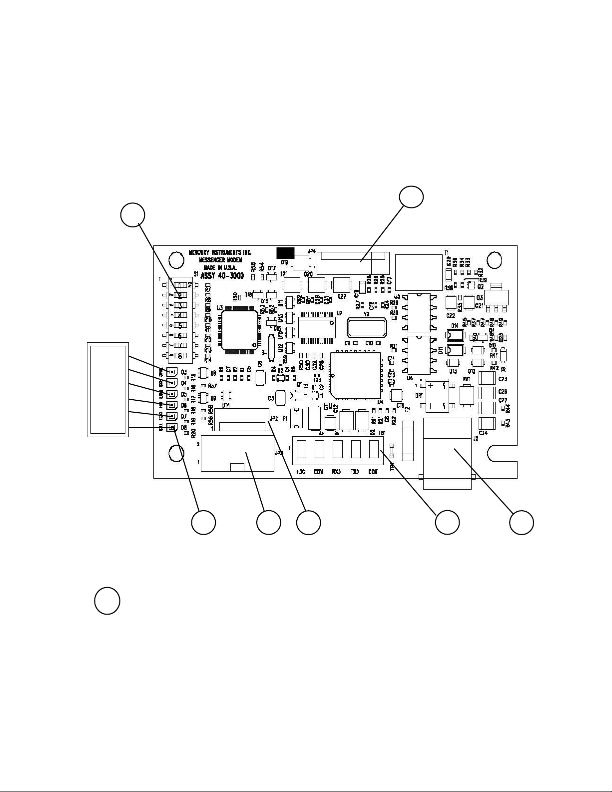
Board Layout
(P/N 40-3000)
7
Page 8
1
1 Status LEDs (6 total) Top to Bottom:
LED#1 - "RING", Ring
LED#2 - "RXD", Receive Data
LED#3 - "PWR", Power
LED#4 - "OH", Off Hook
LED#5 - "DCD", Carrier Detected
LED#6 - "TXD", Transmit Data
3
4
5
6
Page 9

Messenger Modem Board
Parts Identification
2 Switch Configuration, from Top to Bottom (8 total):
(Note: OFF position is toward edge of board)
Switch Positions
OFF ON
Sw#1 - Baud Rate, 1200 2400
Sw#2 - Line Share / Line Surrender enable disable
Sw#3 - Answer Incoming Calls enable disable
Sw#4 - Wake-up on 1 Ring S0 Rings (default 9)
Sw#5 - Wake-up on Serial Data, enable disable
Sw#6 - Unused
Sw#7 - Configuration Mode enabled disable
Sw#8 - Serial Data Mode, RS-232 CMOS
When Switch 4 is set to ‘On’ the number of rings the modem will wake on is controlled
by the value of S0. The default value for S0 is 9, but it may be easily changed using the
Messenger Modem Configuration Software (see Appendix C)
When Switch 7 is set to “Off” the unit will go into configuration mode until the switch is
changed back or 10 minutes has passed. If the unit timed out with the switch in the
“Off” position it will automatically disable the configuration mode. To put the unit back
into conguration mode it is necessary to Move switch 7 to “ON”, Wake the Modem, and
move switch 7 back to the “Off” position.
3 JP3 - Connector (2x5-pins) for CMOS-level serial data
from any of the Mini-Max family of main boards
4 JP2 - Connector (6-pins) sometimes used as a power
connection to the modem board
5 TB1 - Terminal Strip (5-lug) connections,
(assigned functions, left to right:)
+DC COM TXD RXD COM
6 J2 - Connector (RJ-11) telephone line connection
7 JP4 - Connector (8 pin) RS232 Communication and Configuration
Page 9
Page 10

Messenger Modem
®
Messenger Modem DIP Switch Settings
After a switch position is changed, remove power for 10 seconds
(Set Baud Rate switch to 1200 baud for analog cellular operation)
Switch settings for:
Mini-Max, including Sentry, ERX and Pulse Accumulator
(Except with use of external serial connector)
2400 Baud
X
1200 Baud
Enable Line Share
Enabled Ring Detect
Wake up on 1 Ring
Enable Wake-up on RS-232
Always On
Configuration Mode
RS-232 Mode
(Note: DIP Switch as viewed when RJ11 connector is at bottom-right of board)
1
X
2
X
3
X
4
X
5
X
6
X
7
X
8
Off On
Disable Line Share
Disable Ring Detect
Wake up on User Defined # of Rings
Disable Wake-up on RS-232
Serial Pass thru
CMOS Mode (w/ internal ribbon cable)
Notes: a) The Disable Ring Detect feature is available starting with the version-3 board w/ firmware 2.14.
b) Set switches 2, 3, 4 & 7 according to individual site requirements.
Page 10
Page 11
Messenger Modem
®
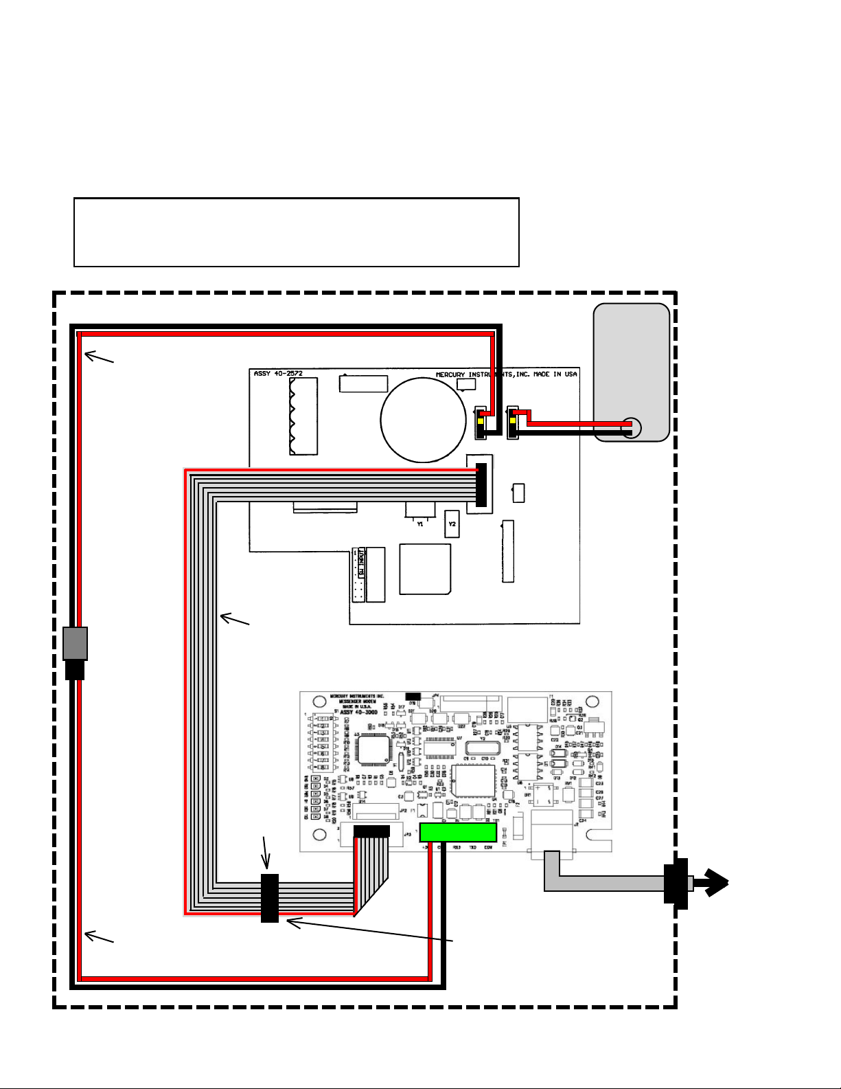
Messenger Modem Wiring Diagram
internal modem, w/o external case connector
for:
Mini-Max, Mini-Max AT, Mini-Max ATX, Sentry, Sentry X, ERX and Pulse Accumulator
Notes:
1. Set baud rate in instrument to 2400 at item 126
2. Set Communication Delays to 25 seconds at items 171 & 172
4 CELL
Alkaline
Battery
Pack
40-2596
or
40-2595
Power Disconnect
Cable
40-2876
(Not used in Pulse
Accumulator)
Mini-Max Board p/n 40-2572-xx
J3
J4
Power Cable
40-2820-5
Ribbon Cable
40-2739 rev. ‘B’ or later
Messenger Modem Board p/n 40-3000
Serial access
port to MMX
board. Unplug
ribbon cable
from Messen-
ger Modem JP3
prior to use.
JP3
J5
TB1
J2
NOTE: Use Configuration/Calibration Cable
(p/n 40-2696-1) or MPA (p/n 40-2620) to
make a serial link at access port. Unplug
the ribbon cable from modem JP3 prior to
attempting a serial connection. Use only
the MPA at main board J5 when attempting
firmware upgrades.
To
telephone
line
Page 11
Page 12

Messenger Modem
®
Messenger Modem DIP Switch Settings
After a switch position is changed, remove power for 10 seconds
(Set Baud Rate switch to 1200 baud for analog cellular operation)
Switch settings for:
Mini-Max, including Sentry, ERX and Pulse Accumulator
( with pass-thru external serial connector)
1200 Baud
Enable Line Share
Enabled Ring Detect
Wake up on 1 Ring
Enable Wake-up on RS-232
Always On
Configuration Mode
RS-232 Mode
(Note: DIP Switch as viewed when RJ11 connector is at bottom-right of board)
1
X
2
X
3
X
4
X
5
X
6
X
7
X
8
Off On
Disable Line Share
Disable Ring Detect
Wake up on User Defined # of Rings
Disable Wake-up on RS-232
Serial Pass thru
CMOS Mode (w/ internal ribbon cable)
2400 Baud
X
Notes: a) The Disable Ring Detect feature is available starting with the version-3 board w/ firmware 2.14.
b) Set switches 2, 3, 4 & 7 according to individual site requirements.
Page 12
Page 13
Messenger Modem
®
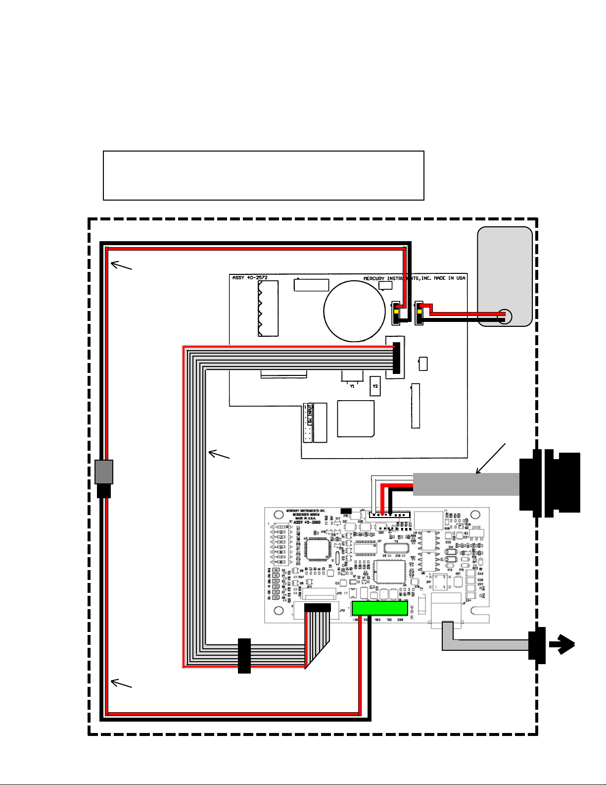
Messenger Modem Wiring Diagram
internal modem, w/pass thru connector
for:
Mini-Max, Mini-Max AT, Mini-Max ATX, Sentry, Sentry X, ERX and Pulse Accumulator
Notes:
1. Set baud rate in instrument to 2400 at item 126
2. Set Communication Delays to 25 seconds at items 171 & 172
4 CELL
Alkaline
Battery
Pack
40-2596
or
40-2595
Power Disconnect
Cable
40-2876
(Not used in Pulse
Accumulator)
Mini-Max Board p/n 40-2572-xx
J3
J4
Power Cable
40-2820-5
Ribbon Cable
40-2739 rev. ‘B’ or later
JP3
J5
Serial Pass-Thru
Cable Assy. 40-4918
TB1
J2
NOTE: Use Serial Cable (p/n 40-1629) at
external case connector to make a serial
link to instrument.
Use MPA (p/n 40-2620) at main board J5
when attempting firmware upgrades.
Dust Cap
To
telephone
line
Page 13
Page 14

Messenger Modem
®
Messenger Modem DIP Switch Settings
After a switch position is changed, remove power for 10 seconds
(Set Baud Rate switch to 1200 baud for analog cellular operation)
Switch settings for:
Mini-Max w/ external shorting plug serial connector
1200 Baud
Enable Line Share
Enable Ring Detect
Wake up on 1 Ring
Enable Wake-up on RS-232
Always On
Configuration Mode
RS-232 Mode
(Note: DIP Switch as viewed when RJ11 connector is at bottom-right of board)
1
X
2
X
3
X
4
X
5
X
6
X
7
X
8
Off On
Disable Line Share
Disable Ring Detect
Wake up on Defined # of Rings
Disable Wake-up on RS-232
Serial Pass thru
CMOS Mode
2400 Baud
X
Notes: a) The Disable Ring Detect feature is available starting with the version-3 board w/ firmware 2.14.
b) Set switches 2, 3, 4 & 7 according to individual site requirements.
Page 14
Page 15
Messenger Modem
®
Messenger Modem Wiring Diagram
internal modem, CMOS to RS-232 converter Bd. w/ ext. case connector & Shorting Plug
for:
Mini-Max, Mini-Max AT, Mini-Max ATX, Sentry, Sentry X, ERX and Pulse Accumulator
Notes:
1. Set baud rate in instrument to 2400 at item 126
2. Set Communication Delays to 25 seconds at items 171 & 172
4 CELL
Alkaline
Battery
Pack
40-2596
or
40-2595
Power Disconnect
Cable
40-2876
(Not used in Pulse
Accumulator)
Mini-Max Board p/n 40-2572-xx
J3
J4
NOTE: Unplug the CMOS to RS-232 converter
board from main board J5 prior to plugging in
the MPA when attempting firmware upgrades.
Messenger Modem Board p/n 40-3000
TB1
TxD RxD COM
J5
CMOS to RS-232
Converter Bd and
Cable Assy. with
Shorting Plug
Shorting
Plug
40-2717-3
To
telephone
line
Power Cable
40-2820-5
Page 15
Page 16

Messenger Modem
®
Messenger Modem DIP Switch Settings
After a switch position is changed, remove power for 10 seconds
(Set Baud Rate switch to 1200 baud for analog cellular operation)
Switch settings for:
Mini-Max w/ external serial connector
1200 Baud
Enable Line Share
Enable Ring Detect
Wake up on 1 Ring
Enable Wake-up on RS-232
Always On
Configuration Mode
RS-232 Mode
(Note: DIP Switch as viewed when RJ11 connector is at bottom-right of board)
1
X
2
X
3
X
4
X
5
X
6
X
7
X
8
Off On
Disable Line Share
Disable Ring Detect
Wake up on defined # of Rings
Disable Wake-up on RS-232
Serial Pass thru
CMOS Mode (w/ internal ribbon
cable)
2400 Baud
X
Notes: a) The Disable Ring Detect feature is available starting with the version-3 board w/ firmware 2.14.
b) Set switches 2, 3, 4 & 7 according to individual site requirements.
Page 16
Page 17

Messenger Modem
®
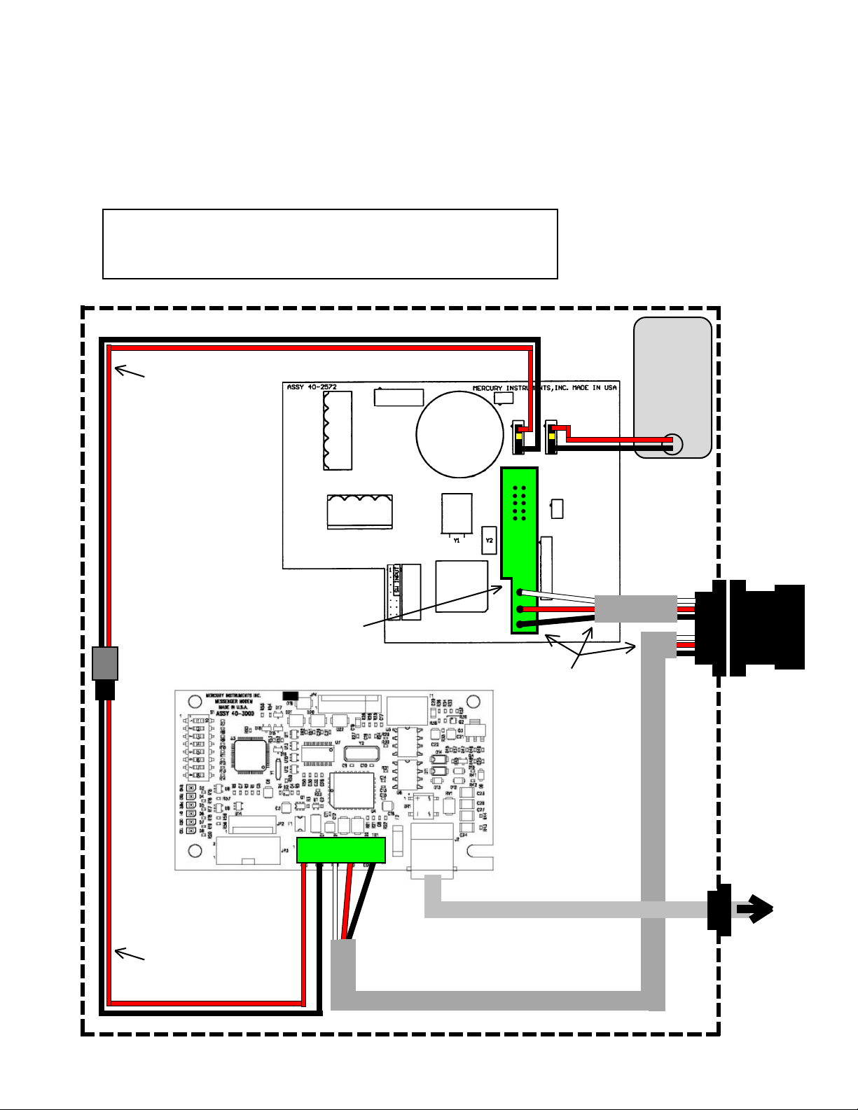
Messenger Modem Wiring Diagram
internal modem, CMOS to RS-232 converter Bd. w/ ext. case connector
for:
Mini-Max, Mini-Max AT, Mini-Max ATX, Sentry, Sentry X, ERX and Pulse Accumulator
Notes:
1. Set baud rate in instrument to 2400 at item 126
2. Set Communication Delays to 25 seconds at items 171 & 172
4 CELL
Alkaline
Battery
Pack
40-2596
or
40-2595
Power Disconnect
Cable
40-2876
(Not used in Pulse
Accumulator)
Mini-Max Board p/n 40-2572-xx
J3
J4
NOTE: Unplug the CMOS to RS-232 converter
board from main board J5 prior to plugging in
the MPA when attempting firmware upgrades.
JP3
Messenger Modem
Board p/n 40-3000
JP4
TB1
TxD RxD COM
J5
CMOS to RS-232
Converter Bd and
Cable Assy.
Dust
Cap
Serial Pass-Thru
Cable Assy.
40-4916
J2
To
telephone
line
Power Cable
40-2820-5
Page 17
Page 18

Messenger Modem
®
Messenger Modem DIP Switch Settings
After a switch position is changed, remove power for 10 seconds
(Set Baud Rate switch to 1200 baud for analog cellular operation)
Switch settings for:
Mini-AT
1200 Baud
Enable Line Share
Enable Ring Detect
Wake up on 1 Ring
Enable Wake-up on RS-232
Always On
Configuration Mode
RS-232 Mode
(Note: DIP Switch as viewed when RJ11 connector is at bottom-right of board)
1
X
2
X
3
X
4
X
5
X
6
X
7
X
8
Off On
Disable Line Share
Disable Ring Detect
Wake up on Defined # of Rings
Disable Wake-up on RS-232
Serial Pass thru
CMOS Mode (w/ internal ribbon
cable)
2400 Baud
X
Notes: a) The Disable Ring Detect feature is available starting with the version-3 board w/ firmware 2.14.
b) Set switches 2, 3, 4 & 7 according to individual site requirements.
Page 18
Page 19

Messenger Modem
®
Messenger Modem Wiring Diagram
internal modem, connected to Modem Port (TB-2)
for:
Mini-AT
Notes:
1. Set baud rate in instrument to 2400 at item 272
2. Set Communication Delays to 25 seconds at items 171 & 172
TB2
Rxd
Txd
COM
J6
J8
J7
Messenger Modem Board p/n 40-3000
Mini-AT Board p/n 40-2335
6 CELL
Alkaline
Battery
Pack
40-1595
or
40-1865
JP3
Battery Cable
40-2565-10
TB1
TxD RxD COM
J2
3-Cond Serial Cable
40-2133-8
RS-232 Conn. &
Cable Assy.
40-1728
Dust Cap
To
telephone
line
Page 19
Page 20

Messenger Modem
®
Messenger Modem DIP Switch Settings
After a switch position is changed, remove power for 10 seconds
(Set Baud Rate switch to 1200 baud for analog cellular operation)
Switch settings for:
Mini-AT
1200 Baud
Enable Line Share
Enable Ring Detect
Wake up on 1 Ring
Enable Wake-up on RS-232
Always On
Configuration Mode
RS-232 Mode
(Note: DIP Switch as viewed when RJ11 connector is at bottom-right of board)
1
X
2
X
3
X
4
X
5
X
6
X
7
X
8
Off On
Disable Line Share
Disable Ring Detect
Wake up on Defined # of Rings
Disable Wake-up on RS-232
Serial Pass thru
CMOS Mode (w/ internal ribbon
cable)
2400 Baud
X
Notes: a) The Disable Ring Detect feature is available starting with the version-3 board w/ firmware 2.14.
b) Set switches 2, 3, 4 & 7 according to individual site requirements.
Page 20
Page 21

Messenger Modem
®
Messenger Modem Wiring Diagram
internal modem, connected to Serial Port (J6)
for:
Mini-AT
Notes:
1. Set baud rate in instrument to 2400 at item 126
2. Set Communication Delays to 25 seconds at items 171 & 172
TB2
Rxd
Txd
COM
J6
J8
J7
Messenger Modem Board p/n 40-3000
Mini-AT Board p/n 40-2335
6 CELL
Alkaline
Battery
Pack
40-1595
or
40-1865
JP3
Battery Cable
40-2565-10
TB1
TxD RxD COM
JP4
J2
3-Cond Serial Cable
40-2937
Dust Cap
Serial Pass-Thru
Cable Assy.
40-4916
To
telephone
line
Page 21
Page 22

Messenger Modem
®
Messenger Modem DIP Switch Settings
After a switch position is changed, remove power for 10 seconds
(Set Baud Rate switch to 1200 baud for analog cellular operation)
Switch settings for:
ER
1200 Baud
Enable Line Share
Enable Ring Detect
Wake up on 1 Ring
Enable Wake-up on RS-232
Always On
Configuration Mode
RS-232 Mode
(Note: DIP Switch as viewed when RJ11 connector is at bottom-right of board)
1
X
2
X
3
X
4
X
5
X
6
X
7
X
8
Off On
Disable Line Share
Disable Ring Detect
Wake up on Defined # of Rings
Disable Wake-up on RS-232
Serial Pass thru
CMOS Mode (w/ internal ribbon
cable)
2400 Baud
X
Notes: a) The Disable Ring Detect feature is available starting with the version-3 board w/ firmware 2.14.
b) Set switches 2, 3, 4 & 7 according to individual site requirements.
Page 22
Page 23

Messenger Modem
®
Messenger Modem Wiring Diagram
internal modem
for:
ER
Notes:
1. Set baud rate in instrument to 2400 at item 588
2. Set Communication Delays to 25 seconds at items 775 & 776
ER Board p/n 40-1896
6 CELL
Alkaline
Battery
Pack
40-1595
or
40-1865
U3
J1
BT2
J17
S3
J6
Messenger Modem Board p/n 40-3000
J2
S2
J4
J8
J9
J3
U12
U4
TB1
Rx
J12
Tx
Gnd
RS-232 Conn. &
Cable Assy.
40-1728
Dust Cap
Battery Cable
40-2565-5
JP3
3-Cond Serial Cable
40-2133-8
TB1
TxD RxD COM
J2
To
telephone
line
Page 23
Page 24

Messenger Modem
®
Messenger Modem DIP Switch Settings
After a switch position is changed, remove power for 10 seconds
(Set Baud Rate switch to 1200 baud for analog cellular operation)
Switch settings for:
ECAT
(Turn Switch 5 On)
1200 Baud
Enable Line Share
Enable Ring Detect
Wake up on 1 Ring
Enable Wake-up on RS-232
Always On
Configuration Mode
RS-232 Mode
(Note: DIP Switch as viewed when RJ11 connector is at bottom-right of board)
1
2
3
X
4
X
5
6
7
8
X
Off On
2400 Baud
X
Disable Line Share
X
Disable Ring Detect
Wake up on Defined # of Rings
Disable Wake-up on RS-232
X
X
Serial Pass thru
X
CMOS Mode (w/ internal ribbon
cable)
Notes: a) The Disable Ring Detect feature is available starting with the version-3 board w/ firmware 2.14.
b) Set switches 2, 3, 4 & 7 according to individual site requirements.
Page 24
Page 25

Messenger Modem
®
Messenger Modem Wiring Diagram
internal modem
for:
ECAT
Notes:
1. Set baud rate in instrument to 2400 at item 126
2. Set Communication Delays to 25 seconds at items 171 & 172
6 CELL
Alkaline
Battery
Pack
40-1595
or
40-1865
ECAT Board p/n 40-1563
Messenger Modem Board p/n 40-3000
SCIB Cable
p/n 40-1674
RS-232 Conn. &
Cable Assy.
40-1580
Dust Cap
SCIB Board
p/n 40-1671
ECAT
Battery Cable
40-1304
Battery Cable
40-2565-10
JP3
3-Cond Serial Cable
40-2133-8
TB1
TxD RxD COM
J2
To
telephone
line
Page 25
Page 26

Messenger Modem
®
Verification (via MasterLink)
To verify that the installation of the integral modem was successful and the instrument is working properly,
obtain a modem link with the instrument using MasterLink software.
• Start MasterLink and select Instrument | Establish Link on the main menu line
• Click the appropriate check box in the Instrument Type above the Site List.
• With the Site List dialog box open, click on Add and enter the required information
• Insure the Site Name, Site Location, Site ID, Site ID 2, Instrument Access Code, Site Phone, and
Modem Port are correct. (Modem Port must be set to “None”)
• Click OK , then click EXIT when completed
• Select Setup | Communications on the main menu line
• Ensure Modem Connection Baud Rate is set to 2400 baud
• Check to see if the correct Connector (Com Port) is selected
• Try making a call to the remote site, even if the Modem Init String blank. If the call fails, most likely the
host modem's profile is incompatible. Refer to Need Help on page 27 for further information on determining
the Modem Init String
• After the Modem Init String has been determined and inserted, select Instrument | Establish Link on the
main menu line
• Select the site entered above (click to highlight)
• Click on the Modem button in the lower left corner Site List window to start the call
• Follow the progress by watching the Traffic Light in the lower left corner of the MasterLink screen
Red indicates: Not Linked to Instrument
Yellow indicates: Trying to Link to Instrument
Green indicates: Established a Link to Instrument
• When the Traffic Light goes green, the status box to the right of the light will indicate the instrument type
and the name of the site. If Site Unknown is displayed, the site ID numbers at item 200 & 201 did not match
any of the Site List entries
• Once linked, click on the red bell (upper right corner) to Display and Clear Alarms.
• To complete the call, select Instrument | Disconnect Link. Verify the Traffic Light goes red
Page 26
Page 27

Messenger Modem
®
Need Help?
If you encounter problems while using the Messenger Modem, follow these steps:
HOST COMPUTER:
1. Make sure your computer, your modem and the cables that connect them are all
working properly.
2. Make sure you're not running software that may conflict with using the
communication ports (infrared, PDAs, etc).
3. In MasterLink, go to Setup on the main menu line. Select Communications and
ensure that the Modem Connection section is correct.
Connector = usually Com-2 or Com-3 but may be something else
Baud Rate = 2400
Modem Init String = modem specific *
Dial Type = Tone
Dial Prefix = blank
* Usually requires a set of modem commands, specific to the modem being used
4. Use Terminal or HyperTerminal (or some other terminal communications
package) to check if communications between the host computer and modem can
be established. Test by typing “AT” and then press Enter. If the modem is
working, the on-screen response will be either "0" or "OK". If there is no
response, check the program settings for proper baud rate and com port selection.
Reset the modem to its factory defaults by turning the modem power off and then
back on, or by typing AT&f and then press Enter. The response should be "0" or
"OK". Exit Terminal and start MasterLink.
Page 27
Page 28

Messenger Modem
5. To establish a modem connection (Carrier Detect) with a Messenger Modem, Error Control in the
host modem must be set to Off.. The command(s) to turn off Error Control may vary depending on
the host modem’s manufacturer. To determine the proper Init String for the host modem, first use
Window’s Control Panel to verify that the driver for the host modem is installed. If your operating
system is greater than Windows98, then
®
• Click Help on the MasterLink’s Main Menu.
• Click About MasterLink32
• Click the System Info button
• After the screen refreshes, click the plus sign “+” next to Components
• Click on Modem
• After the right-side of the screen refreshes, find the line that contains Error Control Off
• Note the command for Error Control Off
• Combine the above command with “&f” (&f should always preceed any other commands)
• Place the combined commands into MasterLink’s Setup|Communications Modem Init
String field.
Below are several examples of modem init strings for both internal modems and external modems.
Internal Modems: External Modems:
&f &m0 &f &m0
&f /n0 &f &k0 &q6
&f /n1 &f +ES=1,0,1;
INSTRUMENT MODEM:
1. Ensure all instrument and modem cables are properly connected, e.g. phone line, battery power
and serial connections.
2. Ensure that the modems DIP switches are in the correct positions.
3. Check that the instrument’s baud rate is correctly set to 2400.
4. Unplug the modem's main power, wait 30 seconds and plug the main power back in. The modem
should cycle through its LED test. Wait for all the LEDs to go out before attempting to call the
instrument.
Page 28
Page 29

Messenger Modem
®
Technical Support
If these steps don't help you find a solution to your problem, you can contact Mercury
Instruments Technical Support by calling
(513) 272-1111 or by fax (513) 272-0211.
When calling, make sure to turn on your computer and start Windows. You should
be ready to give information on the following:
1. The firmware version of the Messenger Modem. (2.12, 2.15, etc.)
2. The versions of your Windows operating system (98, XP, 2000 etc.)
3. The brand and model of your Host modem
4. The COM port and BAUD RATE settings.
5. The phone number of the remote location.
Also, be prepared to answer the following questions:
√ Have you successfully linked to the modem before? If so, have
you changed any of your system hardware or software since then?
√ Can you duplicate the series of steps that result in your problem?
√ Did an error message appear? If so, what was it?
For more information on Mercury Instruments or it's products, please feel free to call
us at (513) 272-1111.
Page 29
Page 30

Messenger Modem
®
Page 30
Page 31

Messenger Modem
®
Appendix A
Basic Telephone Line Information
Revised Sept 1, 2005
Page 31
Page 32

Messenger Modem
Terminology:
®
Page 32
Page 33

Messenger Modem
®
Typical Telephone Line Specs:
Page 33
Page 34

Messenger Modem
®
Typical Telephone Line Specs:
Page 34
Page 35

Messenger Modem
®
Typical Telephone System:
Page 35
Page 36

Messenger Modem
®
Typical Modem Session:
Page 36
Page 37

Messenger Modem
®
Typical Modem Session:
(Cont.)
Page 37
Page 38

Messenger Modem
®
Page 38
Page 39

Messenger Modem
®
Appendix B
Basic Telephone Line Troubleshooting
Revised Sept 1, 2005
Page 39
Page 40

Messenger Modem
®
Telephone Line Test Adapter
p/n 40-2968
Since modem operation can be adversely affected by improper phone line voltages, use the
Telephone Line Test Adapter (shown below) and the procedure on the next page to determine
the voltages for a POTS (analog) phone connection.
Page 40
Page 41

Messenger Modem
®
Telephone Line Troubleshooting
Page 41
Page 42

Messenger Modem
®
Additional Information
Page 42
Page 43

Messenger Modem
®
Appendix C
Modem Configuration Software
Page 43
Page 44

Messenger Modem
®
1.0 Introduction
This Modem Configuration software has been designed to simplify the process of installing and
maintaining Mercury Instrument’s M3K Messenger Modems. It allows the user to:
Read the current value of all settings;
Determine the modem’s firmware version;
View, on the screen, the state of each of the DIP switches and the meaning of the current setting of each;
Change the current value of any of all primary settings;
Save a copy of the values of all the primary settings and store them for later retrieval;
Easily restore the values of all settings to known factory defaults;
Read the current value of all of the modem’s settings and capture them to a text file.
2.0 Installation
The Messenger Modem Configuration Software may be installed on any computer that has at least
one serial port and an XP operating system with service pack 2. A USB-to-serial adapter will suffice
in lieu of a traditional comm port, as long as it is configured as a virtual comm port with a port number
in the range of 1-32.
There are a handful of files that must be installed. By default, they will all be installed in the
c:\Program Files\Mercury Instruments\ folder. If that folder does not exist, it will be automatically
created. During installation the user may elect to install the files in some other location.
The installation is accomplished by simply double-clicking the Modem Configuration Software.exe
file.
Page 44
Page 45

Messenger Modem
3.0 Getting Started
On the modem, ensure that DIP switch 7 is set to OFF. All other switch settings are irrelevant to this
process. Connect the computer’s serial port to the configuration port (JP4) of the modem. This connection may be most simply accomplished with an off-the shelf straight-thru serial cable attached to
the computer’s comm port, a traditional Mercury Instruments serial cable, such as a 40-1629, and a
Mercury Instruments 40-1728 Internal RS-232 Cable. The white wire of the 40-1728 cable should be
positioned next to the JP4 marking on the board. On the other end of JP4 two pins will remain unused.
Once connected, start the Modem Configuration software. Select the proper comm port in the dropdown box in the upper right area of the screen. ‘Click Read From Modem’. A progress dialog should
appear. When all the necessary information is read from the modem, the progress dialog will disappear and the status of the modem will be displayed.
Menu Bar Drop Down box
®
Comm Port Selection
Version of the
Modem firmware
DI
DDip switches 1,2 and 6 Tool Tip indicating the
are ‘ON’ meaning of the current
4.0 Features Switch 1 setting
4.1 Definition of ‘Primary Settings’
As a consequence of the technology and components used in the design of the Messenger
Modem, there are in excess of 100 settings that may be manipulated. The vast majority of
these are of no interest to the average user in everyday operation. Those that are of consequence have been designated as ‘Primary’ settings. These are the only ones that the user can
modify by means of this software.
Page 45
Page 46

Messenger Modem
All of the Primary settings are S-Registers. There are a number of settings that are known by
discrete AT commands. Some of those will be discussed later, under the ‘View All’ feature.
4.2 Reading and Writing to modem
The ‘Read From Modem’ button updates the screen with the current value of the Primary Settings.
Conversely, the ‘Write To Modem’ transfers the values shown on the screen to the modem. It is inherent
in the design that all values sent to the modem are written permanently. Some modems require an
additional command, such as ‘AT&W’ to lock in the new settings. Such is not the case with the Messenger Modem.
The most common scenario is to first read the modem, change only those settings that need to be
changed and update the modem with the Write button. Settings that the user did not edit will be be
‘updated’ with the same value that they originally had. That is, there will be no change to them.
As an additional feature, any value that is shown on the screen as ‘- -‘ (dash/space/dash) will cause the
software to not write any value for that setting. This permits a different scenario than the aforementioned
Read/Edit/Write sequence. Immediately after launching the application, all settings show values of ‘- -‘.
If only one of two settings are to be modified, the user may simply enter the new values and click
‘Write’.
®
All values are validated against rough limits after the Write button is clicked and before
anything is sent to the modem. Should a warning message appear, make the proper adjustment and write again.
4.3 Switch display
An area of the screen is dedicated to reflecting the current setting of each of the 8 DIP switches on the
modem. This display is updated each time ‘Read From Modem’ button is clicked. Switches that are
ON appear darker, and a bar is shown at the top of that switch. OFF switches are lighter in color and
have a bar at the bottom.
The ‘Help’ button next to the switches evokes a form that lists the purpose of each switch and
defines the meaning of OFF and ON for that switch.
If the mouse is briefly held over any of the switches a box, known as a Tool Tip will appear
that reveals details about that switch’s setting.
4.4 ‘View All’ button
It was previously noted that the modem has a great number of settings which cannot be
modified with this software. These may be manipulated using HyperTerminal, and they could
take on odd values by some electronic anomaly. Should that happen, the modem may cease to
operate properly. As an aid in detecting such an eventuality, the Modem Configuration Software includes a provision for reading the current value of all available settings. This may be
accomplished with the ‘View All’ button. When this is clicked, the modem is interrogated, and
all S-Register and AT settings are displayed. This is accomplished by the traditional technique
Page 46
Page 47

Messenger Modem
of issuing an AT&V command. The text stream that results is written to a temporary file and
displayed with the help of Notepad.
All of Notepad’s functionality is available with this feature. Word Wrap should be on. The
screen may be saved to a permanent file using File > Save. This is useful to maintain a reference list of settings, and can be useful when E-mailed to Mercury Instruments field service.
This is a read-only function. Since the settings are displayed in Notepad, notes may be added,
or the data may be changed. However, there is no way to send this information back to the
modem.
4.5 Set to Defaults
Mercury Instruments has designed a set of ‘Factory Default’ values for both Primary and ‘View All’
settings. This is similar to the common AT&F command. This can be useful whenever there is concern
that one of the less visible ‘View All’ settings has been upset. Clicking ‘Set Modem To Defaults’ establishes the modem to a known state.
Setting defaults affects ALL settings. Changes to the Primary settings will not be obvious until
‘Read From Modem’ is subsequently clicked.
®
4.6 Loading and saving files
Any set of values for the Primary settings may be stored as a file for reference. Such files can be saved
at any location and by any name chosen by the user. These files may later be recalled and the values in
that file send to the modem. Note that this only pertains to the Primary settings. This facilitates the
configuration of several modems to a ‘standard’ configuration. In order to ensure is fully ‘standardized, it
is suggested that ‘Set Modem To Defaults’ be clicked prior to recalling and ‘Loading’ a set of Primary
values.
There is special significance to a set of values saved to a file named ‘Default’ in the same
directory as the application. If such a file exists, the values therein will be called up every time
the software is launched and be used to fill the boxes on the screen, replacing the traditional
dashes.
4.7 Exit
Upon exiting the program, the user will is reminded to set DIP Switch 7 back to the ON position so that
the modem will exit configuration and revert to normal pass-thru mode. The software then issues a
command to put the modem back to low-power sleep mode. If DIP switch 7 is not changed to pass
thru mode, the modem will time-out in ten (10) minutes and go into pass-thru mode
5.0 Advanced topics
5.1 How to modify ‘Factory Defaults’
Page 47
Page 48

Messenger Modem
Clicking ‘Set Modem To Defaults’ sets both the Primary and the ‘View All’ settings to default values. It
is possible to modify the software to customize values for the Primary settings. A file can be found in the
same directory as the application called Config_Fixed.xml. This can be viewed and/or modified using
any text editor. This file defines default values for Primary settings. The portion of the file in which the
default value of register S7 is defined appears as:
<ATS7>
<ControlLayout>Basic</ControlLayout>
<Description>Wait for Carrier</Description>
<ATWhat>S7</ATWhat>
<Units>Secs</Units>
<DefaultValue />
<ATRequestCommand>ATS7?</ATRequestCommand>
<ATSendCommandPrefix>ATS7=</ATSendCommandPrefix>
<ValidationMinimum>7</ValidationMinimum>
<ValidationMaximum>99999</ValidationMaximum>
<ATResponseLength>10</ATResponseLength>
</ATS7>
®
Since nothing is specified as a default value, the Set ModemTo Defaults value will prevail. In
order to define the default value as 92, the file could be edited (in part) to:
<Units>Secs</Units>
<DefaultValue>92</DefaultValue>
<ATRequestCommand>ATS7?</ATRequestCommand>
Anyone familiar with XML files will recognize and be comfortable with the syntax. But XML
syntax is unique and non-obvious. Editing this file is therefore discouraged except for users
experienced in the use of XML and unless this is required to satisfy a critical need.
Page 48
Page 49

Messenger Modem
®
Page 49
 Loading...