

Mercury MerCruiser MCM 4.3L ALPHA, MerCruiser MCM 4.3LH BRAVO, MerCruiser MCM 4.3L EFI ALPHA Service Manual
Page 1

MAINTENANCESERVICE MANUAL NUMBER 25
IMPORTANT INFORMATION
Section 1B - Maintenance
Table of Contents
Tools 1B-2. . . . . . . . . . . . . . . . . . . . . . . . . . . . . .
Lubricants / Sealants / Adhesives 1B-2. . . . .
Maintenance Schedules 1B-3. . . . . . . . . . . . . .
Maintenance Intervals 1B-3. . . . . . . . . . . . .
Gas Sterndrive 1B-3. . . . . . . . . . . . . . . . . . . . . .
Routine Maintenance * 1B-3. . . . . . . . . . . .
Scheduled Maintenance * 1B-4. . . . . . . . . .
Engine and Tune-Up Specifications 1B-5. . . .
MCM (Sterndrive) 1B-5. . . . . . . . . . . . . . . . .
Fluid Capacities 1B-6. . . . . . . . . . . . . . . . . . . . .
Sterndrive Engines 1B-6. . . . . . . . . . . . . . .
Sterndrives 1B-6. . . . . . . . . . . . . . . . . . . . . .
20-Hour Break-In Period 1B-7. . . . . . . . . . . . .
After Break-in Period 1B-7. . . . . . . . . . . . . . . .
End of First Season Checkup 1B-7. . . . . . . . .
Specifications 1B-8. . . . . . . . . . . . . . . . . . . . . . .
Fuel Recommendations 1B-8. . . . . . . . . . .
Test For Alcohol Content In Gasoline 1B-10
Power Steering Fluid 1B-10. . . . . . . . . . . . . . . .
Coolant for Closed Cooling System 1B-10. . . .
Crankcase Oil 1B-11. . . . . . . . . . . . . . . . . . . . . .
Overfilled Crankcase Oil 1B-11. . . . . . . . . . .
Checking Engine Oil Level / Filling 1B-12. .
Changing Oil and Filter 1B-12. . . . . . . . . . . . . . .
Changing Water Separating Fuel Filter 1B-13.
Power Steering System 1B-15. . . . . . . . . . . . . .
Checking Fluid Level 1B-15. . . . . . . . . . . . . .
Engine Cold 1B-15. . . . . . . . . . . . . . . . . . . . .
Filling and Bleeding 1B-16. . . . . . . . . . . . . . .
1
B
Closed Cooling System 1B-17. . . . . . . . . . . . . .
Checking Coolant Level 1B-17. . . . . . . . . . .
Flushing System 1B-18. . . . . . . . . . . . . . . . . .
Lubrication 1B-20. . . . . . . . . . . . . . . . . . . . . . . . .
Throttle Cable 1B-20. . . . . . . . . . . . . . . . . . . .
Shift Cable 1B-20. . . . . . . . . . . . . . . . . . . . . . .
Engine Coupler /
U-Joint Shaft Splines 1B-21. . . . . . . . . . . . .
Sterndrive Drive
Shaft Extension Models 1B-22. . . . . . . . . . .
Cleaning Flame Arrestor 1B-22. . . . . . . . . . . . .
Top Mounted Flame Arrestor 1B-23. . . . . . .
Serpentine Drive Belt 1B-23. . . . . . . . . . . . . . . .
Component Location 1B-23. . . . . . . . . . . . . .
Serpentine Belt Routing 1B-24. . . . . . . . . . . . . .
S/N 0L619083 and Below 1B-24. . . . . . . . . .
S/N 0L619084 and Above 1B-25. . . . . . . . .
Inspection 1B-26. . . . . . . . . . . . . . . . . . . . . . .
Replacing and/or Adjusting Tension 1B-26.
Ignition Timing 1B-27. . . . . . . . . . . . . . . . . . . . . .
Thunderbolt V Models 1B-27. . . . . . . . . . . . .
EFI 1B-28. . . . . . . . . . . . . . . . . . . . . . . . . . . . .
Cold Weather or Extended Storage 1B-29. . . .
Precautions 1B-29. . . . . . . . . . . . . . . . . . . . . .
Power Package Layup 1B-31. . . . . . . . . . . .
Draining Instructions 1B-33. . . . . . . . . . . . . .
Draining Sterndrive 1B-38. . . . . . . . . . . . . . .
Recommissioning 1B-39. . . . . . . . . . . . . . . . .
90-861328--1 NOVEMBER 1999 Page 1B-1
Page 2
MAINTENANCE SERVICE MANUAL NUMBER 25
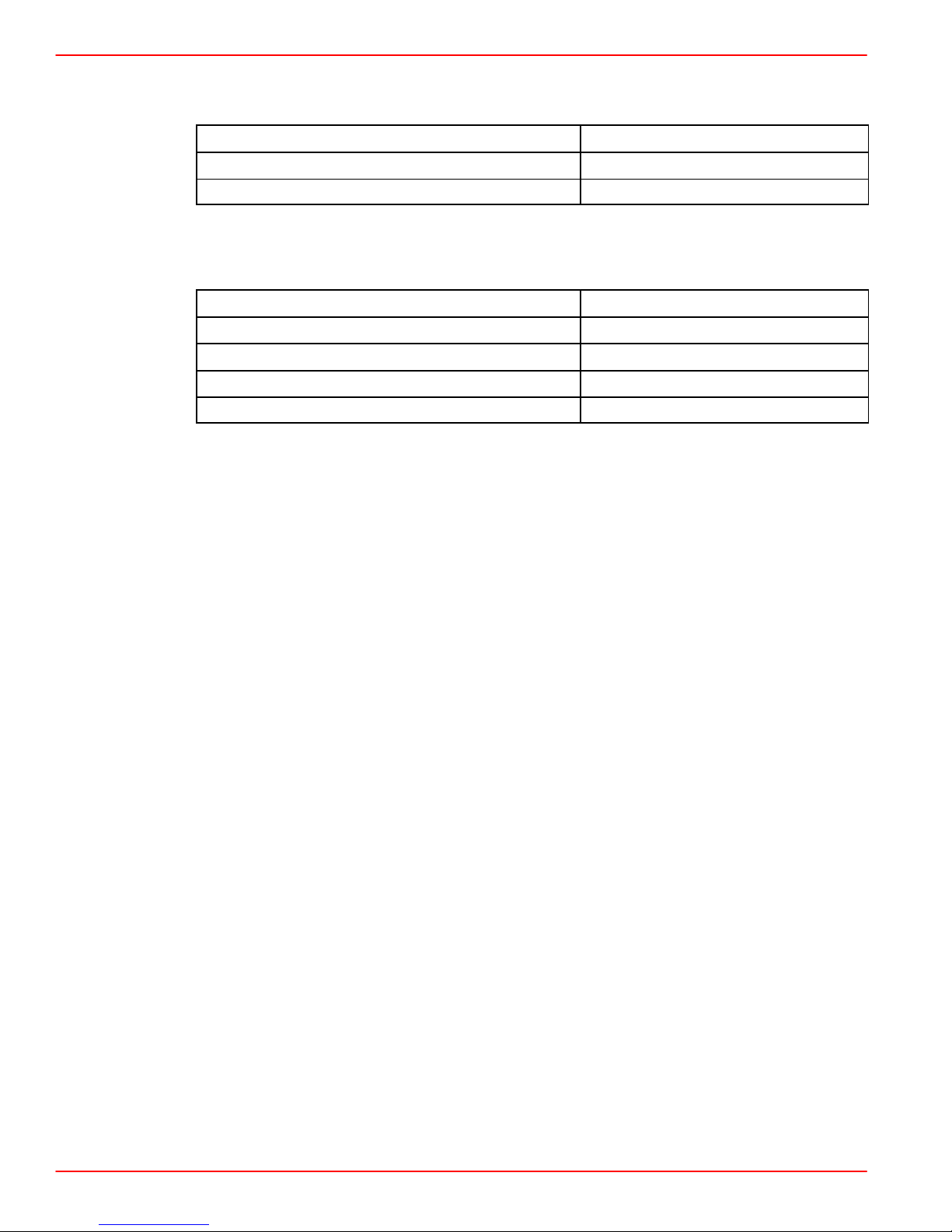
Tools
Description Part Number
Timing Light 91-99379
Quicksilver Scan Tool 91-823686A2
Lubricants / Sealants / Adhesives
Description Part Number
Quicksilver Liquid Neoprene 92-25711--3
Quicksilver 2-4-C Marine Lubricant With Teflon 92-825407A3
Loctite Pipe Sealant With Teflon Obtain Locally
Quicksilver U-Joint and Gimbal Bearing Grease 92-828052A2
Page 1B-2 90-861328--1 NOVEMBER 1999
Page 3
Maintenance Schedules
Maintenance Intervals
Maintenance intervals and the tasks to be performed, as shown in this current schedule, or
as found in a previously printed schedules, are generally based on an average boating
application and environment. However, individual operating habits and personal maintenance preferences can have an impact on the suggested intervals. In consideration of these
factors, Mercury MerCruiser has adjusted some maintenance intervals and corresponding
tasks to be performed. In some cases, this may allow for more individual tasks to be
performed in a single visit to the serving dealer, rather than multiple visits. Therefore, it is
very important that the boat owner and servicing dealer discuss the current Maintenance
Schedule and develop appropriate maintenance intervals to coincide with the individual
operating habits, environment, and maintenance requirements.
Always disconnect battery cables from battery BEFORE working around electrical
systems components to prevent injury to yourself and damage to electrical system
should a wire be accidentally shorted.
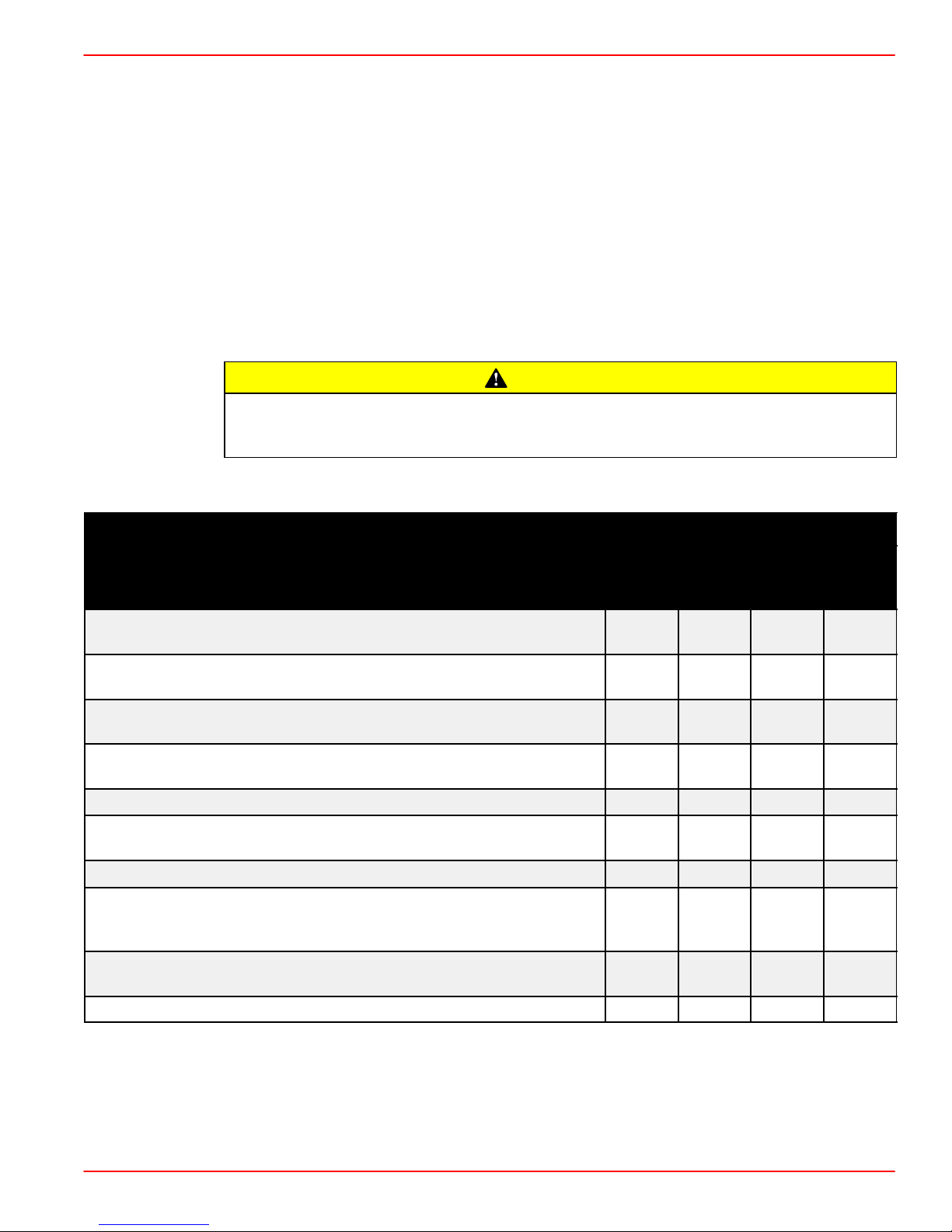
Gas Sterndrive
MAINTENANCESERVICE MANUAL NUMBER 25
CAUTION
Routine Maintenance *
Each
Day
Start
Check crankcase oil (interval can be extended based on experience).
If operating in salt, brackish or polluted waters, flush cooling system after each use.
Check drive unit oil level, trim pump oil level and power steering
pump fluid level.
Check water pickups for debris or marine growth. Check water
strainer and clean. Check coolant level.
Inspect drive unit anodes and replace if 50 percent eroded.
Inspect fuel pump sight tube and have pump replaced if fuel is
present.
Check battery connections and fluid level.
Lubricate propeller shaft and the retorque nut (if operating in only
freshwater, this maintenance may be extended to every four
months).
Operating in Saltwater Only: treat engine surface with corrosion
guard.
Clean air filter every 50 hours of operation.
Each
Day
End
Weekly
Every
Two
Months
* Only perform maintenance which applies to your particular power package
Standard Models
Horizon Models
90-861328--1 NOVEMBER 1999 Page 1B-3
Page 4
MAINTENANCE SERVICE MANUAL NUMBER 25
Gas Sterndrive(Continued)
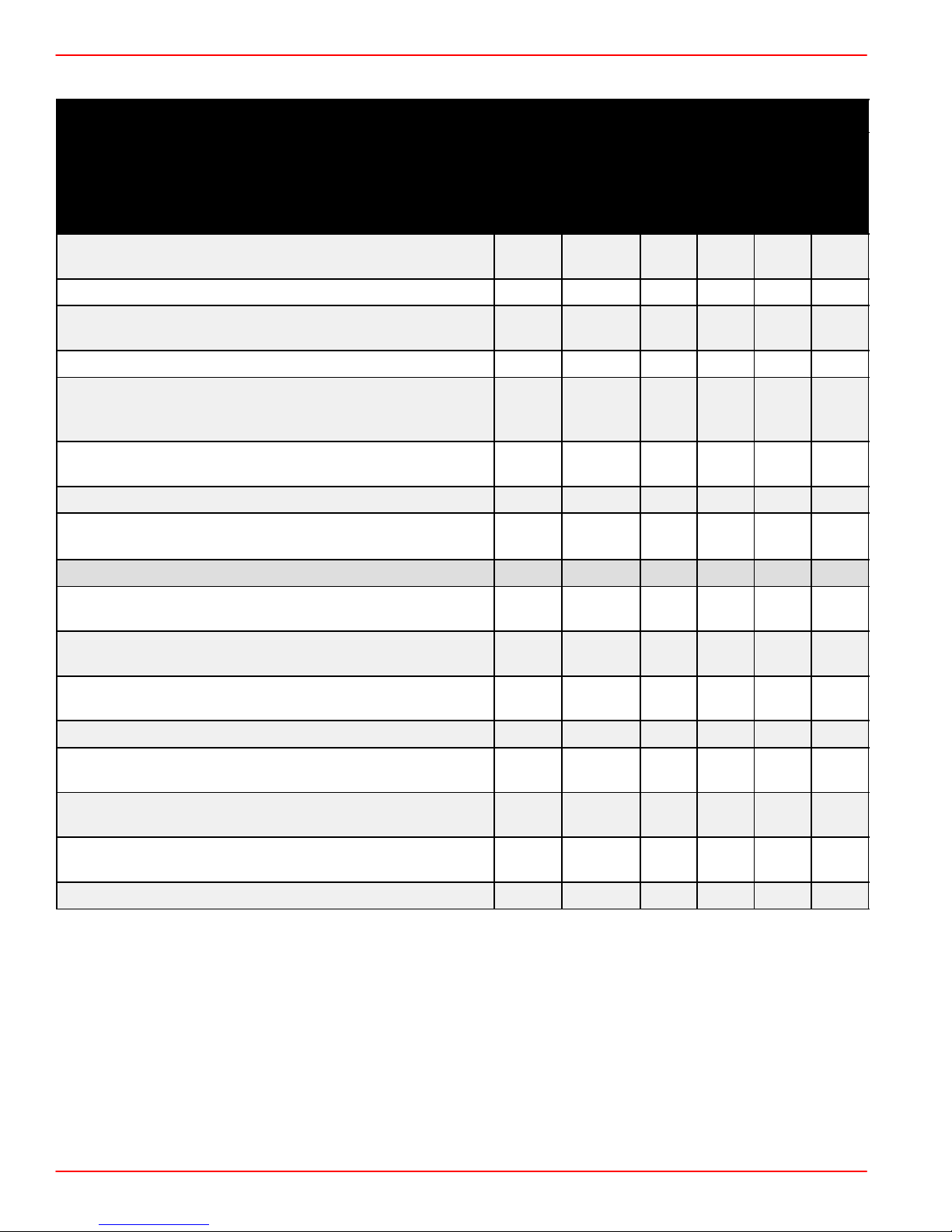
Scheduled Maintenance *
Touch-up paint power package and spray with corrosion
guard.
Annu-
ally
Every
100
hours or
Annually
Every
200
hours
or 3
years
Every
300
hours
or 3
years
Change crankcase oil and filter.
Change drive unit oil and retorque connection of gimbal
ring to steering shaft.
Replace fuel filter(s).
Check steering system and remote control for loose,
missing or damaged parts. Lubricate cables and link-
ages.
Inspect U-joints, splines and bellows. Check clamps.
Check engine alignment. Lubricate U-joints splines.
Lubricate gimbal bearing and engine coupler.
Check continuity circuit for loose or damaged connec-
tions. Test MerCathode unit output on Bravo Models.
Retorque engine mounts.
Every
2
years
Every
5
years
Check spark plugs, wires, distributor cap and ignition
timing. Check and adjust idle speed.
Clean flame arrestor and crankcase ventilation hoses.
Replace PCV valve.
Check electrical system for loose, damaged or corroded
fasteners.
Inspect condition and tension of belts.
Check cooling system and exhaust system hose clamps
for tightness. Inspect both systems for damage or leaks.
Disassemble and inspect seawater pump and replace
worn components.
Clean seawater section of closed cooling system.
Clean, inspect and test pressure cap.
Replace coolant.
* Only perform maintenance which applies to your particular power package
Standard Models
Horizon Models
Whichever Occurs First
Interval will be reduced if not using extended life coolant.
Lubricate engine coupler every 50 hours if operated at idle for prolonged periods of time.
Page 1B-4 90-861328--1 NOVEMBER 1999
Page 5
Engine and Tune-Up Specifications
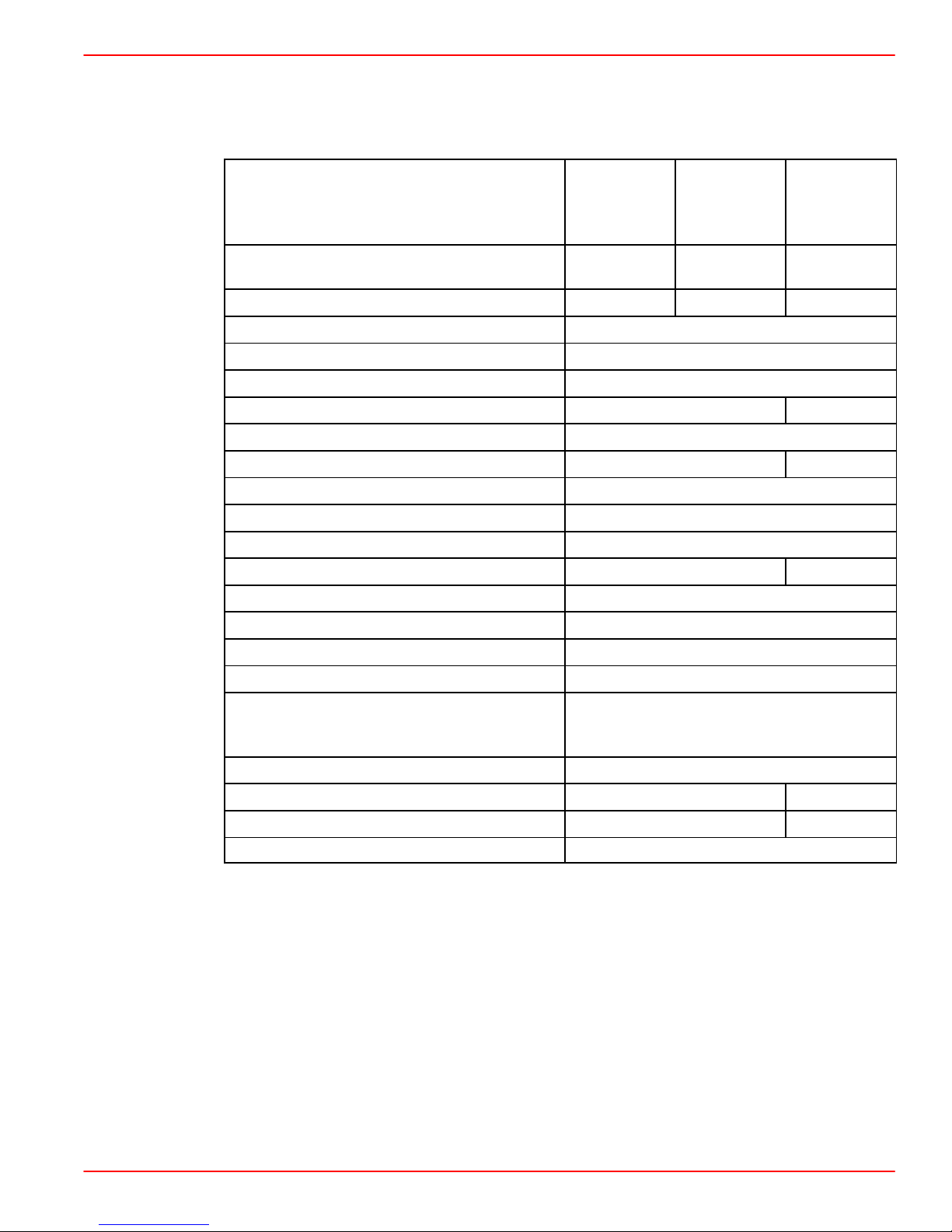
MCM (Sterndrive)
MAINTENANCESERVICE MANUAL NUMBER 25
2
2
MCM 4.3L
EFI
ALPHA /
BRAVO
1
210
(188)2
1
157
(146)
Model
Propshaft Horsepower
(SAV1 Rating)
MCM 4.3L
ALPHA /
BRAVO
190 205 (190)
MCM 4.3LH
ALPHA /
BRAVO
Propshaft Kilowatts (SAV1 Rating) 142 153 (142)
Number of Cylinders V-6
Displacement 262 cid (4.3 l)
Bore / Stroke - in. (mm) 4.0 x 3.48 (101.6 x 88.4)
Compression Ratio 9.4:1 9.4:1
Compression Pressure Minimum 100 psi (690 kPa)
Idle rpm In Neutral
3
Maximum rpm (at WOT)
650 rpm
3
5
4400-4800 rpm
7
600 rpm
5
Oil Pressure (at 2000 rpm) Minimum 30 psi (207 kPa)
Minimum Oil Pressure (at Idle) Minimum 4 psi (28 kPa)
Fuel Pressure (1800 rpm) 3-7 psi (21-48 kPa) 30 psi ( kPa)
Electrical System 12 V Negative (–) Ground
Alternator Rating 55 or 65 amp
8
2
Minimum Battery Requirements 375 cca / 475 mca / 90 Ah
Firing Order 1-6-5-4-3-2
AC - MR43LTS
Spark Plug Type
Champion - RS12YC
NGK - BPR6EFS
Spark Plug Gap .045 in. (1.1 mm)
Timing (at idle rpm)
4
10° BTDC 8° BTDC
Preliminary Idle Mixture 1 1/4 Turns DNA
Thermostat 160° F (71° C)
1
Power Rated in Accordance with NMMA (National Marine Manufacturers’ Association) rating procedures.
2
Power Rated in Accordance with SAV1 rating procedures. This rating procedure is used to certify that the
engine complies with “Stage 1” Bodensee and Swiss Regulations. Horsepower differences shown result from
differences in test rpm, allowable test tolerances, and/or installation of special kit components.
3
Measured using an accurate service tachometer with engine at normal operating temperature.
4
Timing must be set using a special procedure as outlined in the appropriate section of this manual. Timing can-
not be properly set using the conventional method.
5
A special procedure must be followed to adjust idle rpm. Consult your Authorized Mercury MerCruiser Dealer
before attempting this procedure.
6
Idle speed on EFI models is not adjustable.
7
Minimum recorded compression in any one cylinder should not be less than 70 percent of the highest recorded
cylinder.
8
Serial Number Break for 65 Amp alternator: OL619083 and above.
90-861328--1 NOVEMBER 1999 Page 1B-5
Page 6
MAINTENANCE SERVICE MANUAL NUMBER 25
Fluid Capacities
NOTICE
Unit Of Measurement: U.S. Quarts (Liters)
All capacities are approximate fluid measures.
Sterndrive Engines
Model All Models
1
2
4-1/2 (4.3)
15 (14.1)
NOTICE
Sterndrives
Crankcase Oil (With Filter)
Seawater Cooling System
Closed Cooling System 20 (19)
1
Always use dipstick to determine exact quantity of oil or fluid required.
2
Seawater Cooling System capacity information is for winterization use only.
Unit Of Measurement: U.S. Fluid Ounces (Milliliters)
All capacities are approximate fluid measures.
Model ALPHA ONE
Drive Unit Oil Capacity (With Gear Lube Monitor) 64 (1892)
Model BRAVO ONE BRAVO TWO BRAVO THREE
Drive Unit Oil Capacity
(With Gear Lube Monitor)
88 (2603) 104 (3076) 96 (2839)
Page 1B-6 90-861328--1 NOVEMBER 1999
Page 7

20-Hour Break-In Period
IMPORTANT: The first 20 hours of operation is the engine break-in period. Correct
break-in is essential to obtain minimum oil consumption and maximum engine performance. During this break-in period, the following rules must be observed:
• Do not operate below 1500 rpm for extended periods of time for first 10 hours. Shift into
gear as soon as possible after starting and advance throttle above 1500 rpm if condi-
tions permit safe operation.
• Do not operate at one speed consistently for extended periods.
• Do not exceed 3/4 throttle during first 10 hours. During next 10 hours, occasional opera-
tion at full throttle is permissible (5 minutes at a time maximum).
• Avoid full throttle acceleration from IDLE speed.
• Do not operate at full throttle until engine reaches normal operating temperature.
After Break-in Period
To help extend the life of your Mercury MerCruiser power package, the following recommendations should be considered:
• Use a propeller that allows the engine to operate at or near the top of the maximum rpm
range (refer to “Specifications” section) when at full throttle with a normal boat load.
MAINTENANCESERVICE MANUAL NUMBER 25
• Operation at 3/4 throttle setting or lower is recommended. Refrain from prolonged op-
eration at maximum (full throttle) rpm.
End of First Season Checkup
At the end of the first season of operation, an Authorized Mercury MerCruiser Dealer should
be contacted to discuss and/or perform various scheduled maintenance items. If you are
in an area where the product is operated continuously (year-round operation), you should
contact your dealer at the end of the first 100 hours of operation, or once yearly , whichever
occurs first.
90-861328--1 NOVEMBER 1999 Page 1B-7
Page 8

MAINTENANCE SERVICE MANUAL NUMBER 25
CA261
Specifications
Fuel Recommendations
IMPORTANT: Use of improper gasoline can damage your engine seriously. Engine
damage resulting from use of improper gasoline is considered misuse of engine, and
damage caused thereby will not be covered under the limited warranty.
FUEL RATINGS
Mercury MerCruiser engines will operate satisfactorily when using a major brand of
unleaded gasoline as follows:
USA and Canada - having a posted pump Octane Rating of 87 (R+M)/2 minimum. Premium
gasoline [92 (R+M)/2 Octane] is also acceptable. DO NOT use leaded gasoline.
Outside USA and Canada
- having a posted pump Octane Rating of 90 RON minimum.
Premium gasoline (98 RON) is also acceptable. If unleaded gasoline is not available, use
a major brand of leaded gasoline.
CA291
USING REFORMULATED (OXYGENATED) GASOLINES (USA ONLY)
This type of gasoline is required in certain areas of the USA. The two types of “oxygenates”
used in these fuels are Alcohol (Ethanol) or Ether (MTBE or ETBE). If Ethanol is the “oxygen-
ate” that is used in the gasoline in your area, refer to “Gasolines Containing Alcohol.”
These “Reformulated Gasolines” are acceptable for use in your Mercury MerCruiser
engine.
VAPOR LOCKING
Fuels containing alcohol and winter grade fuels will aggravate vapor lock problems. A vapor
lock condition can be identified by the following problems:
• Engine starts and, upon advancing throttle, shuts off and will not restart.
• If engine does restart, it shuts off when advancing throttle.
• Engine i s d i fficult to restart after operating the boat and then leaving the engine off for 1 to
3 hours.
Other factors may combine to increase vapor locking. These factors include but are not limited to:
• air temperature
• fuel tank location
• fuel supply system
• engine coolant temperature
• temperature and vacuum of fuel to engine
• engine compartment air temperature and ventilation
Other conditions should be ruled out before treating the problem as vapor locking.
Page 1B-8 90-861328--1 NOVEMBER 1999
Page 9
CA618
GASOLINES CONTAINING ALCOHOL
If the gasoline in your area contains either “methanol” (methyl alcohol) or “ethanol” (ethyl
alcohol), you should be aware of certain adverse effects that can occur. These adverse
effects are more severe with “methanol.” Increasing the percentage of alcohol in the fuel can
also worsen these adverse effects.
Some of these adverse effects are caused because the alcohol in the gasoline can absorb
moisture from the air, resulting in a separation of the water/alcohol from the gasoline in the
fuel tank.
The fuel system components on your Mercury MerCruiser engine will withstand up to 10%
alcohol content in the gasoline. We do not know what percentage your boat’s fuel system
will withstand. Contact your boat manufacturer for specific recommendations on the boats
fuel system components (fuel tanks, fuel lines and fittings). Be aware that gasolines
containing alcohol may cause increased:
• Corrosion of metal parts.
• Deterioration of rubber or plastic parts.
• Fuel permeation through rubber fuel lines.
MAINTENANCESERVICE MANUAL NUMBER 25
• Starting and operating difficulties.
WARNING
FIRE AND EXPLOSION HAZARD: Fuel leakage from any part of fuel system can be
a fire and explosion hazard which can cause serious bodily injury or death. Careful
periodic inspe c tion of entire fuel system is mandatory, particularly after storage. All
fuel components including fuel tanks, whether plastic metal or fiberglass, fuel
lines, fittings, fuel filters and carburetors/fuel injection components should be inspected for leakage, softening, hardening, swelling or corrosion. Any sign of leakage or deterioration requires replacement before further engine operation.
Because of possible adverse effects of alcohol in gasoline, it is recommended that only alcohol-free gasoline be used where possible. If only fuel containing alcohol is available, or if
the presence of alcohol is unknown, increased inspection frequency for leaks and abnormalities is required.
IMPORTANT: When operating a Mercury MerCruiser engine on gasoline containing
alcohol, storage of gasoline in the fuel tank for long periods should be avoided. Long
periods of storage, common to boats, create unique problems. In cars alcohol-blend
fuels normally are consumed before they can absorb enough moisture to cause
trouble, but boats often sit idle long enough for phase separation to take place. In
addition, internal corrosion may take place during storage if alcohol has washed protective oil films from internal components.
90-861328--1 NOVEMBER 1999 Page 1B-9
Page 10
MAINTENANCE SERVICE MANUAL NUMBER 25
Test For Alcohol Content In Gasoline
The following is an acceptable and widely used field procedure for the detection of alcohol
in gasoline. Use any small transparent bottle or tube that can be capped and is, or can be,
provided with graduations or a mark at about 1/3 full. A pencil mark on a piece of adhesive
tape may be used.
PROCEDURE
1. Fill the container with water to the mark.
2. Add fuel almost to fill the container, leaving some air space, then cap the container. The
proportions of fuel to water are not critical, but there should be 2 to 3 times as much fuel
as water.
3. Shake container vigorously and allow it to sit upright for 3 to 5 minutes. If the volume
of water appears to have increased, alcohol is present. If you are not sure, there is no
need for concern. If the dividing line between water and fuel becomes cloudy, use the
middle of the cloudy band.
Power Steering Fluid
Use Quicksilver Power Trim and Steering Fluid or automatic transmission Fluid (ATF)
Dexron III.
Coolant for Closed Cooling System
CAUTION
Alcohol or Methanol base antifreeze or plain water, are not recommended for use
in fresh water section of cooling system at any time.
We recommend that the coolant section of closed cooling system be filled with Extended
Life Ethylene Glycol 5/100 Antifreeze/Coolant mixed 50/50 with purified water. In areas
where the possibility of freezing does not exist, it is permissible to use a solution of rust inhibitor and water (mixed to manufacturer’s recommendations).
If any non-compatible coolant is added to this coolant, coolant must be changed every 2
years or 400 hours, whichever occurs first. All coolants other than Extended Life 5/100
Ethylene Glycol Antifreeze/Coolant must be changed every 2 years or 400 hours, whichever
occurs first.
Mercury MerCruiser V-8 engines can use any type of permanent antifreeze or any brand
antifreeze solution that meets GM specification 1825M.
Page 1B-10 90-861328--1 NOVEMBER 1999
Page 11
CA693
Crankcase Oil
To help obtain optimum engine performance and to provide maximum protection, we
strongly recommend the use of Quicksilver 4-Cycle 25W-40 Marine Engine Oil. This oil is
a special blend of 25-weight and 40-weight oils for marine engines. If not available, a good
grade, straight weight, detergent automotive oil of correct viscosity, with an API
classification of SH,CF/CF-2, may be used.
In those areas where Quicksilver 4-Cycle 25W-40 Marine Engine Oil or a recommended
straight weight oil are not available, a multiviscosity 20W-40 (SH, CF/CF-2) or , a s a second
but less preferable choice, 20W-50, with API service ratings of SH, CF/CF-2 may be used.
IMPORT ANT: The use of non-detergent oils, multi-viscosity oils (other than Quicksilver 25W-40 or a good quality 20W-40 or 20W-50), synthetic oils, low quality oils or oils
that contain solid additives are specifically not recommended.
The chart below is a guide to crankcase oil selection. The oil filter should always be changed
with oil.
MAINTENANCESERVICE MANUAL NUMBER 25
Quicksilver 4-Cycle Marine Engine Oil
SAE 20W
Overfilled Crankcase Oil
Overfilled crankcases (oil level being too high ) can cause a fluctuation or drop in oil pressure
and rocker arm “clatter” on Mercury MerCruiser engines. The over-full condition results in
the engine crankshaft splashing and agitating the oil, causing it to foam (become aerated).
The aerated oil causes the hydraulic valve lifters to “bleed down.” This, in turn, results in
rocker arm “clatter” and loss of engine performance, due to the valves not opening properly.
Care must be taken when checking engine oil level. Oil level must be maintained between
the ADD mark and the FULL mark on the dipstick. T o ensure that you are not getting a “false
reading,” make sure the following steps are done before checking the oil level.
• Boat “at rest” in the water, or
SAE 30W
32° F
0
° C
AIR TEMPERATURE
50
10
° F
° C
SAE 40W
70534
• If boat is on a trailer , raise or lower bow until the boat is setting at the approximate angle
that it would be if setting “at rest” in the water.
• Allow sufficient time for oil to drain into the crankcase if engine has just been run or oil
has just been added.
90-861328--1 NOVEMBER 1999 Page 1B-11
Page 12

MAINTENANCE SERVICE MANUAL NUMBER 25
Checking Engine Oil Level / Filling
IMPORTANT: ENGINE CRANKCASE OIL MUST BE CHECKED AT INTERVALS
SPECIFIED IN “MAINTENANCE SCHEDULE” CHART. It is normal for an engine to use
a certain amount of oil in the process of lubrication and cooling of the engine. The
amount of oil consumption is greatly dependent upon engine speed, with
consumption being highest at wide-open-throttle and decreasing substantially as
engine speed is reduced.
1. Stop engine and allow boat to come to a rest.
2. Allow oil to drain back into oil pan - approximately 5 minutes.
3. Remove dipstick.
4. Wipe clean and reinstall. Push dipstick all the way into dipstick tube.
5. Remove dipstick and note the oil level.
6. Oil level must be between the FULL or OP RANGE and ADD marks.
7. If oil level is below ADD mark, proceed to Steps 8. and 9.
8. Remove oil filler cap from valve rocker arm cover.
9. Add required amount of oil to bring level up to, but not over, the FULL mark on dipstick.
Changing Oil and Filter
1. Start engine and run until it reaches normal operating temperatures.
IMPORTANT: Change oil when engine is warm from operation, as it flows more freely,
carrying away more impurities.
2. Stop engine.
3. Remove drain plug from oil pan or from oil drain hose.
IMPORTANT: If engine is factory equipped with Quick Drain Oil Hose, pull tether
through bilge drain before removing drain plug from oil drain hose.
NOTE: If drain plug is not accessible because of boat construction, oil may be removed
through dipstick tube, using a Quicksilver Crankcase Oil Pump. (See Quicksilver Accessory
Guide.)
4. After oil has drained completely, reinstall drain plug (if removed) and tighten securely.
5. Remove and discard oil filter and its sealing ring.
6. Coat sealing ring on new filter with engine oil and install. Tighten filter securely (following
filter manufacturer’s instructions). Do not overtighten.
7. Fill crankcase with oil. See “Specifications” for type of oil and quantity.
8. Check dipstick to ensure oil level is up to, but not over, FULL or OP RANGE mark on
dipstick.
9. Start engine and check for leaks.
Page 1B-12 90-861328--1 NOVEMBER 1999
Page 13

Changing Water Separating Fuel Filter
WARNING
Be careful when changing water separating fuel filter. Gasoline is extremely
flammable and highly explosive under certain conditions. Be sure ignition key is
OFF. Do not smoke or allow spark or open flame in area when changing fuel filter.
Wipe up any spilled fuel immediately.
WARNING
Make sure no fuel leaks exist before closing engine hatch.
CAUTION
The electric fuel pump and factory installed water separating fuel filter have been
carefully designed to function properly together . Do not install additional fuel filters
and/or water separating fuel filters between fuel tank and engine.
The installation of additional filters may cause:
• Fuel Vapor Locking
• Difficult Warm-Starting
MAINTENANCESERVICE MANUAL NUMBER 25
• Piston Detonation Due to Lean Fuel Mixture
• Poor Driveability
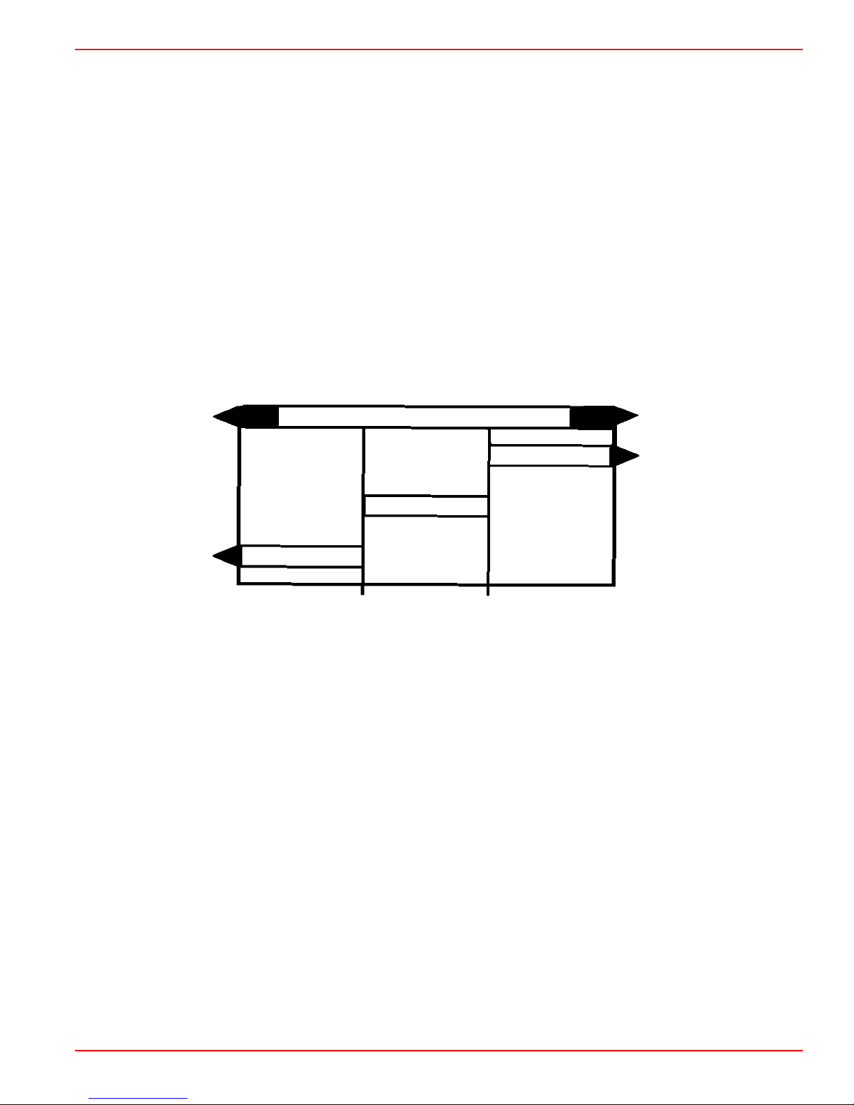
1. Unsnap latch and slide top and bottom cover pieces, if equipped, from around the water
separating fuel filter and bracket.
a
75034
a-Fuel Filter Cover
NOTE: Top and bottom cover pieces are formed with a groove on each side that slides
around the brackets outer edges.
90-861328--1 NOVEMBER 1999 Page 1B-13
Page 14

MAINTENANCE SERVICE MANUAL NUMBER 25
2. Remove water separating fuel filter and sealing ring from mounting bracket and discard.
b
a
70573
a-Fuel Filter
b-Sealing Ring
3. Coat sealing ring on new filter with motor oil.
4. Thread filter onto bracket and tighten securely by hand. Do not use a filter wrench.
5. Start and run engine.
6. Check filter connection for gasoline leaks. If leaks exist, recheck filter installation.
7. Install cover pieces around fuel filter. Be certain top part of cover latches to lower part.
Page 1B-14 90-861328--1 NOVEMBER 1999
Page 15

Power Steering System
Checking Fluid Level
ENGINE WARM
1. Stop engine. Position drive unit so that it is straight back.
2. Remove fill cap / dipstick from power steering pump and note fluid level.
MAINTENANCESERVICE MANUAL NUMBER 25
a
a-Fill Cap / Dipstick
b-Power Steering Pump
3. Level should be between the FULL HOT mark and ADD mark on dipstick.
a-Proper Fluid Level with Engine Warm
4. If level is below ADD mark, but fluid is still visible in pump reservoir , add required amount
of Quicksilver Power Trim and Steering Fluid or automatic transmission fluid (ATF) Dexron III through fill cap opening, to bring level up to FULL HOT mark on dipstick. DO NOT
OVERFILL.
b
74908
a
72518
Engine Cold
5. If fluid is not visible in reservoir, a leak exists in the power steering system. Find cause
and correct.
1. With engine stopped, position drive unit so that it is straight back.
2. Remove fill cap / dipstick from power steering pump and note fluid level.
3. Level should be between FULL COLD mark and bottom of dipstick.
a
a-Proper Fluid Level with Engine Cold
4. If level is below bottom of dipstick, but fluid is still visible in pump reservoir, add required
amount of Quicksilver Power Trim and Steering Fluid or automatic Dexron III transmission fluid (ATF), through fill cap opening, to bring level up to FULL COLD mark on dipstick. DO NOT OVERFILL.
If fluid is not visible in reservoir, a leak exists in the power steering system. Find cause and
correct.
72519
90-861328--1 NOVEMBER 1999 Page 1B-15
Page 16

MAINTENANCE SERVICE MANUAL NUMBER 25
Filling and Bleeding
IMPORTANT: Power steering system must be filled exactly as explained in the following to be sure that all air is bled from the system. All air must be removed, or fluid in
pump may foam during operation and be discharged from pump reservoir. Foamy
fluid also may cause power steering system to become spongy, which may result in
poor boat control.
1. With engine stopped, position drive unit so that it is straight back.
2. Remove fill cap / dipstick from power steering pump.
3. Add Quicksilver Power Trim and Steering Fluid or Dexron III automatic transmission
fluid (ATF), as required, to bring level up to FULL COLD mark on dipstick.
IMPORT ANT: Use only Quicksilver Power Trim and Steering Fluid or Dexron III automatic transmission fluid (ATF), in power steering system.
4. Turn steering wheel back and forth to end of travel in each direction several times.
5. Recheck fluid level and add fluid, if necessary.
6. Install vented fill cap. Tighten securely.
CAUTION
DO NOT operate engine without water being supplied to seawater pickup pump, or
pump impeller may be damaged and subsequent overheating damage to engine
may result.
7. Start engine and run at fast idle (1000-1500 rpm) until engine reaches normal operating
temperature. During this time, turn steering wheel back and forth to end of travel in each
direction several times.
8. Position drive unit so that it is straight back and stop engine.
9. Remove fill cap from pump.
10. Allow any foam in pump reservoir to disperse.
1 1. Check fluid level and add fluid, as required, to bring level up to FULL HOT mark on dip-
stick. DO NOT OVERFILL.
12. Reinstall fill cap. Tighten securely.
IMPORTANT: Drive unit must be positioned straight back and power steering fluid
must be hot to accurately check fluid level.
13. If fluid is still foamy (in Step 5.), repeat Steps 7. through 12. until fluid does not foam and
level remains constant.
Page 1B-16 90-861328--1 NOVEMBER 1999
Page 17

Closed Cooling System
Checking Coolant Level
Allow engine to cool down before removing pressure cap. Sudden loss of pressure
could cause hot coolant to boil and discharge violently. After engine has cooled,
turn cap 1/4 turn to allow any pressure to escape slowly , then push down and turn
cap all the way off.
1. Coolant level in heat exchanger should be full (to bottom of filler neck).
IMPORTANT: When reinstalling pressure cap, be sure to tighten it until it contacts on
filler neck.
2. Coolant level should be between the ADD and FULL marks on coolant recovery reser-
voir with the engine at normal operating temperature.
MAINTENANCESERVICE MANUAL NUMBER 25
CAUTION
a
a-Coolant Recovery Reservoir
72520
90-861328--1 NOVEMBER 1999 Page 1B-17
Page 18

MAINTENANCE SERVICE MANUAL NUMBER 25
Flushing System
If engine is operated in salty, polluted or mineral-laden water, flush seawater cooling system
(preferably after each use) to reduce corrosion and prevent the accumulation of deposits
in the system. Thoroughly flush the seawater cooling system prior to storage.
NOTE: For additional protection against freezing and rust to the exhaust manifolds and
other components, a 50-50 mixture of antifreeze and water can be run through the engine
during Power Package Layup.
1. Install flushing attachment and water hose over the water pickup holes in gear housing.
a
b
a-Flushing Attachment
b-Hose
72693
WARNING
When flushing, be certain the area around propeller is clear , and no one is standing
nearby. To avoid possible injury, remove propeller.
CAUTION
Do not run engine above 1500 rpm when flushing. Suction created by seawater pickup pump may collapse flushing hose, causing engine to overheat.
CAUTION
Watch temperature gauge on dash to ensure that engine does not overheat.
2. Open water tap enough to cool the engine, about ½ of its maximum capacity. Adjust as
required so that the engine does not overheat.
3. With drive in neutral gear , start engine and advance the throttle until the engine reaches
1300 rpm.
IMPORTANT: DO NOT run the engine at idle rpm. Watch engine temperature gauge
on dash. Do not run the engine above 1500 rpm or engine overheating may occur.
4. Run engine for 10 minutes or until the discharge water is clear.
5. Slowly return the throttle to the idle position and turn engine off.
IMPORTANT: DO NOT rapidly advance or return throttle as this can cause water ingestion.
Page 1B-18 90-861328--1 NOVEMBER 1999
Page 19

BOAT IN WATER
MAINTENANCESERVICE MANUAL NUMBER 25
1. Raise drive unit to full UP / OUT position.
2. Install flushing attachment over water pickup holes in gear housing as shown.
3. Attach a water hose between the flushing attachment and a water tap.
a
b
a-Flushing Attachment
b-Hose
4. Lower drive unit to full DOWN / IN position.
72693
CAUTION
Do not run engine above 1500 rpm when flushing. Suction created by seawater pickup pump may collapse flushing hose, causing engine to overheat.
CAUTION
Watch temperature gauge on dash to ensure that engine does not overheat.
5. Partially open water tap (approximately 1/2 maximum capacity). DO NOT use full water
pressure.
6. Place remote control in neutral, idle speed position, and start engine.
7. Operate engine at idle speed in neutral for 10 minutes, then stop engine.
8. Shut off water tap.
9. Raise drive unit to full UP / OUT position.
10. Remove water hose and flushing attachment.
90-861328--1 NOVEMBER 1999 Page 1B-19
Page 20

MAINTENANCE SERVICE MANUAL NUMBER 25
Lubrication
Throttle Cable
1. Lubricate pivot points and guide contact surfaces with SAE 30W motor oil.
a
2 Barrel Carbureted Models EFI Models
a-Pivot Points
b-Guide Contact Surface
Shift Cable
MCM (STERNDRIVE) MODELS
1. Lubricate pivot points and guide contact surfaces with SAE 30W motor oil.
71359
a
b
a
b
a
a
74941
b
Typical Shift Cable
a-Pivot Points
b-Guide Contact Surface
Page 1B-20 90-861328--1 NOVEMBER 1999
b
a
a
72016
Page 21

Engine Coupler / U-Joint Shaft Splines
NOTE: Engine coupler and shaft splines are greased with Quicksilver Engine Coupler
Spline Grease, 92-816391A4; universal joints are greased with Quicksilver 2-4-C Marine
Lubricant.
NOTE: Refer to Mercury MerCruiser Sterndrive Service Manual for sterndrive unit removal
and installation, if necessary.
IMPORTANT: Sterndrive Unit does not have to be removed to grease coupler.
1. Lubricate engine coupler splines through grease fitting on coupler by applying approxi-
mately 8-10 pumps of grease from a typical hand-operated grease gun.
MAINTENANCESERVICE MANUAL NUMBER 25
b
b
a
a
71569
Typical Alpha Drive Coupler Typical Bravo Drive Coupler
IMPORTANT: Later Bravo Models may be equipped with a coupler that is similar to
the Alpha Coupler.
a-Grease Fitting
b-Quicksilver Engine Coupler Spline Grease
72529
a
a
Typical Bravo Drive
a-Quicksilver Engine Coupler Spline Grease
90-861328--1 NOVEMBER 1999 Page 1B-21
a
72531
Page 22

MAINTENANCE SERVICE MANUAL NUMBER 25
Sterndrive Drive Shaft Extension Models
a
a
a
72018
a
Transom End Engine End
a-Grease Fitting
72028
Cleaning Flame Arrestor
WARNING
Avoid gasoline fire or explosion. Gasoline is extremely flammable and highly
explosive under certain conditions. Be careful when cleaning flame arrestor and
crankcase ventilation hoses. Be sure that ignition is OFF. DO NOT smoke or allow
sources of spark or open flame in area when cleaning flame arrestor and crankcase
ventilation hoses.
WARNING
Avoid gasoline fire or explosion. Gasoline is extremely flammable and highly explosive under certain conditions. NEVER use gasoline as a cleaning solvent.
Page 1B-22 90-861328--1 NOVEMBER 1999
Page 23

Top Mounted Flame Arrestor
1. Remove flame arrestor cover.
2. Remove crankcase ventilation hose from fitting on side of flame arrestor housing.
3. Remove flame arrestor.
a-Flame Arrestor
4. Clean flame arrestor in solvent. Blow dry with compressed air.
MAINTENANCESERVICE MANUAL NUMBER 25
a
76501
5. Clean crankcase ventilation hose in solvent. Blow dry with compressed air.
6. Inspect crankcase ventilation hose for cracks or deterioration and replace if necessary.
7. Reinstall flame arrestor and crankcase ventilation hose.
8. Reinstall flame arrestor cover.
Serpentine Drive Belt
Component Location
Avoid possible serious injury. Make sure engine is shut off and ignition key is
removed before inspecting belt.
NOTE: Some models will have components arranged in a different order. All configurations
are not shown. Checking, replacing and adjustment procedures are the same.
WARNING
90-861328--1 NOVEMBER 1999 Page 1B-23
Page 24

MAINTENANCE SERVICE MANUAL NUMBER 25
Serpentine Belt Routing
S/N 0L619083 and Below
Alpha With Power Steering Bravo With Power Steering
Alpha With Closed Cooling Bravo Without Power Steering
Without Power Steering
Alpha With Closed Cooling Bravo With Closed Cooling
and Power Steering and Power Steering
Page 1B-24 90-861328--1 NOVEMBER 1999
Page 25

Serpentine Belt Routing (Continued)
S/N 0L619084 and Above
MAINTENANCESERVICE MANUAL NUMBER 25
76503
76502
Alpha With Power Steering Bravo With Power Steering
76445
Alpha Without Power Steering Bravo Without Power Steering
76463
90-861328--1 NOVEMBER 1999 Page 1B-25
Page 26

MAINTENANCE SERVICE MANUAL NUMBER 25
Inspection
1. Inspect drive belt for the following:
• Excessive wear
• Cracks
NOTE: Minor, transverse cracks (across the belt width) may be acceptable. Longitudinal
cracks (in direction of belt length) that join transverse cracks are NOT acceptable.
• Fraying
• Glazed surfaces
b
a
75130
a-Fraying
b-Cracks
Replacing and/or Adjusting Tension
REMOVAL
1. Loosen 5/8 in. locking nut on adjustment stud.
2. Turn adjustment stud and loosen belt.
3. Remove drive belt.
INSTALLATION AND ADJUSTMENT
4. Install drive belt on pulleys.
5. Adjust tension by loosening 5/8 in. locking nut on adjustment stud. Leave wrench on
adjustment stud.
NOTE: Belt deflection is to be measured on the belt at the location that has the longest distance between two (2) pulleys. Proper tension is 1/4 in. (6 mm) deflection with moderate
thumb pressure.
6. Use 5/16 in. socket and tighten adjusting stud until the correct deflection of the belt is
obtained at location specified above.
Page 1B-26 90-861328--1 NOVEMBER 1999
Page 27

7. While holding adjustment stud at the correct belt tension, tighten 5/8 in. locking nut.
8. Run engine for a short period of time and recheck belt adjustment.
a-5/8 in. Locking Nut
b-5/16 in. Adjusting Stud
Ignition Timing
MAINTENANCESERVICE MANUAL NUMBER 25
a
b
74908
Thunderbolt V Models
1. Connect timing light to number 1 spark plug wire.
2. Connect a shop tachometer to the engine.
IMPORTANT: Before starting the engine, connect a jumper wire from the ignition timing lead to a good ground. This has to be done before the ignition key is turned ON
to lock the ignition module into Base Timing Mode.
3. Before starting the engine, connect jumper wire from timing lead to a good ground.
NOTE: The PUR/WHT timing lead is located towards the front of the engine near the fuel
line or near the distributor, as equipped for your model.
4. Start engine and run at 1300 rpm until it reaches normal operating temperature.
5. Disconnect throttle cable from the carburetor.
6. With engine at idle rpm, adjust the carburetor idle rpm screw to the specified engine idle
rpm.
7. With the engine still at idle rpm, check the ignition timing. If incorrect, rotate the
distributor until timing is correct. Torque clamping screw to 18 lb-ft (25 Nm).
8. Adjust the idle mixture screw. Inward is LEAN, outward is RICH.
9. Recheck ignition timing.
10. Stop engine. Remove timing light, jumper wire and shop tachometer.
IMPORTANT: Timing jumper wire has to be removed or the ignition module will stay
locked in the Base Timing Mode and it will not be able to advance the ignition timing
correctly when the engine rpm is increased.
11. Adjust and reinstall throttle cable. Open and close remote control throttle lever. Ensure
that the carburetor throttle lever is contacting the idle rpm adjusting screw every time.
12. Restart the engine, increase rpm to 1300 then return to idle position slowly and shut the
engine off. Ensure that the carburetor throttle lever is contacting the idle rpm screw.
13. Shut engine off.
90-861328--1 NOVEMBER 1999 Page 1B-27
Page 28

MAINTENANCE SERVICE MANUAL NUMBER 25
EFI
1. Connect timing light to number 1 spark plug wire.
2. Start engine and run at 1300 rpm until it reaches normal operating temperature.
3. Stop engine and connect the scan tool or timing tool to the DLC connector on the EFI
wiring harness.
4. Start engine, allow rpm to stabilize.
NOTE: MEFI-1 models only , manually adjust remote control throttle lever to get 1200 engine
rpm.
NOTE: MEFI-3 models only, ECM will automatically adjust engine rpm to approximately
1200 rpm when put in the service mode on a scan tool or when using the timing tool.
5. Check ignition timing. If incorrect, rotate the distributor until timing is correct. Torque
clamping screw to 18 lb-ft (25 Nm).
6. Recheck ignition timing.
7. Disconnect scan tool or timing tool from DLC connector.
8. If required, return remote control throttle lever to idle position and shut off engine.
9. Restart engine, increase rpm to 1300 then return to idle position slowly. Ensure that
engine returns to idle rpm. Readjust throttle cable, if required.
10. Shut engine off.
Page 1B-28 90-861328--1 NOVEMBER 1999
Page 29

Cold Weather or Extended Storage
Precautions
WARNING
Always disconnect battery cables from battery BEFORE working on fuel system to
prevent fire or explosion.
WARNING
BE CAREFUL while working on fuel system; gasoline is extremely flammable and
highly explosive under certain conditions. Be sure that ignition key is OFF. DO NOT
smoke or allow sources of spark and/or open flames in the area. Wipe up any spilled
fuel immediately.
WARNING
Avoid Fire or Explosion: To prevent a potential fire hazard, be sure that engine compartment is well ventilated and that there are no gasoline vapors present during
starting or fogging of engine.
WARNING
MAINTENANCESERVICE MANUAL NUMBER 25
Avoid Fire or Explosion: Fuel injection system is pressurized during operation. Use
care when removing water separating fuel filter. Fuel could spray on hot engine
causing fire or explosion. Allow engine to cool down before attempting to remove
the water separating fuel filter in the following procedure. Also, hold a clean shop
towel over the water separating fuel filter when removing it to help avoid fuel spraying on the engine.
CAUTION
If boat is in the water, seacock (water inlet valve), if equipped, must be closed until
engine is to be restarted, to prevent water from flowing back into cooling system
and/or boat. If boat is not fitted with a seacock, water inlet hose must be disconnected and plugged to prevent water from flowing back into cooling system and/or
boat. As a precautionary measure attach a tag to the ignition switch or steering
wheel of the boat with the warning that the seacock must be opened or the water
inlet hose reconnected prior to starting engine.
CAUTION
DO NOT operate engine without water flowing through seawater pickup pump, as
pump impeller may be damaged and subsequent overheating damage to engine or
sterndrive unit may result.
CAUTION
If engine is equipped with Closed Cooling System, Closed Cooling section must be
kept filled with a solution of ethylene glycol antifreeze and water (mix antifreeze to
manufacturer’s recommended proportions to protect engine to lowest temperature
to which it will be exposed). DO NOT USE PROPYLENE GLYCOL antifreeze in closed
cooling section. Seawater section, however, must be drained completely.
A discharged battery can be damaged by freezing.
90-861328--1 NOVEMBER 1999 Page 1B-29
CAUTION
Page 30

MAINTENANCE SERVICE MANUAL NUMBER 25
CAUTION
Seawater section of cooling system MUST BE COMPLETELY drained for winter
storage, or immediately after cold weather use, if the possibility of freezing temperatures exists. Failure to comply may result in trapped water causing freeze and/or
corrosion damage to engine.
WARNING
When running engine with boat out of water, be certain that area in vicinity of
propeller is clear and that no person is standing nearby. As a precautionary
measure, it is recommended that the propeller be removed.
CAUTION
DO NOT run engine above 1500 rpm, as suction created by seawater pickup pump
may collapse water supply hose and cause engine to overheat.
WARNING
Be sure that engine compartment is well ventilated and that no gasoline vapors are
present to prevent the possibility of a FIRE or EXPLOSION.
IMPORTANT: Observe the following information to ensure complete draining of cooling system.
• Engine must be as level as possible.
• A wire should be repeatedly inserted into all drain holes to ensure there are no
obstructions in passages.
IMPORT ANT: To prevent threads in manifolds, elbows and cylinder blocks from rusting during storage, reinstall drain plugs. Never leave drain plugs out during storage.
NOTE: If possible, place a container under drains and hoses to prevent water from draining
into boat.
Page 1B-30 90-861328--1 NOVEMBER 1999
Page 31

Power Package Layup
Refer to “Precautions” in this section BEFORE proceeding.
IMPORTANT: Mercury MerCruiser strongly recommends that this service be performed by an Authorized Mercury MerCruiser Dealer. Damage caused by freezing IS
NOT covered by the MerCruiser Limited Warranty.
1. Fill fuel tank(s) with fresh gasoline that does not contain alcohol and a sufficient amount
of Quicksilver Gasoline Stabilizer for Marine Engines to treat gasoline. Follow instructions on container.
2. If boat is to be placed in storage with fuel containing alcohol in fuel tanks (if fuel
without alcohol is not available): Fuel tanks should be drained as low as possible and
Quicksilver Gasoline Stabilizer for Marine Engines added to any fuel remaining in the
tank. Refer to “Fuel Requirements” for additional information.
NOTE: If desired, a portable fuel tank can be used to perform the remainder of the power
package layup procedures. Be sure to add an appropriate amount of Gasoline Stabilizer to
the portable tank.
3. Run engine sufficiently to bring it up to normal operating temperature and allow fuel with
Quicksilver Gasoline Stabilizer to circulate through fuel system.
MAINTENANCESERVICE MANUAL NUMBER 25
NOTICE
4. Shut off engine.
5. Change oil and oil filter.
6. Flush cooling system. Refer to “Flushing Cooling System” procedure.
7. Close the fuel shutoff valve, if equipped. If no fuel shutoff valve is present, a suitable
method must be employed to STOP the flow of fuel from the fuel tank to the engine
before proceeding.
90-861328--1 NOVEMBER 1999 Page 1B-31
Page 32

MAINTENANCE SERVICE MANUAL NUMBER 25
8. Prepare EFI fuel system for extended storage as follows:
a. Allow engine to cool down.
b. Remove the water separating fuel filter.
c. Pour out a small amount of fuel into a suitable container, then add approximately 2
fluid ounces (60 ml) of Quicksilver 2-Cycle Outboard Oil to fuel in the water separat-
ing fuel filter.
d. Reinstall water separating fuel filter.
e. Start and operate engine at idle speed until the water separating fuel filter and fuel
injection system are empty and engine stops.
f. Remove and discard water separating fuel filter.
g. Install new filter.
a
75533
a-Water Separating Fuel Filter
9. Prepare carbureted fuel system for extended storage as follows:
a. Remove flame arrestor assembly and start engine.
b. While operating engine at fast idle (1000-1500 rpm), fog internal surfaces of induc-
tion system and combustion chambers by squirting approximately 8 ounces (227
grams) of Quicksilver Storage Seal or SAE 20W engine oil into carburetor bores.
c. Squirt the remaining 2 ounces (57 g) of Storage Seal (or oil) rapidly into carburetor,
just as the engine begins to stall due to lack of fuel. Allow engine to stop.
10. Turn ignition key to OFF position.
11. Refer to “Flushing Cooling System” and appropriately remove water supply to the seawater pickup pump.
12. Clean flame arrestor and crankcase ventilation hoses and reinstall.
13. Lubricate all items listed in “Lubrication” section.
14. Drain seawater section of cooling system as outlined in “Draining Instructions” section.
15. On Models with Closed Cooling System: Test coolant to ensure that it will withstand
the lowest temperature expected during storage.
16. Service batteries per manufacturer’s instructions.
17. Clean outside of engine and repaint any areas required with Quicksilver Primer and
Spray Paint. After paint has dried, spray Quicksilver Corrosion and Rust Preventive
Type II or wipe down with Quicksilver Storage Seal or SAE 20W engine oil.
18. For sterndrive unit layup, refer to appropriate sterndrive service manual.
NOTE: For additional protection against freezing and rust to the exhaust manifolds and
other components, a 50-50 mixture of antifreeze and water can be run through the engine
during Power Package Layup.
Page 1B-32 90-861328--1 NOVEMBER 1999
Page 33

Draining Instructions
DRAINING SEAWATER (RAW-WATER) COOLED MODELS
NOTICE
Refer to “Precautions” in this section BEFORE proceeding.
IMPORTANT: Engine must be as level as possible to ensure complete draining of
cooling system.
1. Remove drain plugs from bottom of port and starboard manifold fittings.
2. Remove drain plugs (port and starboard) from cylinder block or cylinder block Y-fitting.
CAUTION
Avoid product damage. Do not disturb the Y-fitting when removing the drain plug.
There is an ignition control “Knock Sensor” in the upper hole of the fitting. This sensor must not be loosened or removed. It is tightened to a critical specification at the
factory.
MAINTENANCESERVICE MANUAL NUMBER 25
a
b
Starboard Side Shown (Port Similar)
a-Exhaust Elbow Drain Plug
b-Cylinder Block Drain Plug
c-Y-Fitting (Fuel Injected Only)
d-Cylinder Block Drain Plug (Fuel Injected Only)
e-Knock Sensor
c
d
e
74073
90-861328--1 NOVEMBER 1999 Page 1B-33
Page 34

MAINTENANCE SERVICE MANUAL NUMBER 25
3. Repeatedly clean out drain holes using a stiff piece of wire. Do this until entire system
is drained.
NOTE: It may be necessary to lift, bend or lower hoses to allow water to drain completely
when hoses are disconnected.
4. Remove the engine water circulating pump hose or drain plug, as equipped.
a
b
a
76038
75081
72587
a-Hose, Water Circulating Pump To Thermostat Housing
b-Water Circulating Pump Hose Drain Plug
5. Remove the drain plug from the water tube or Cool Fuel System cooler, as equipped.
a
75018
Some Carbureted Models Fuel Injected Models
a-Drain Plug
6. Remove seawater pump inlet hose as shown.
a-Seawater Inlet Hose
b-Hose To Cooler
7. Crank engine over slightly with starter motor to purge any water trapped in seawater
pickup pump. DO NOT ALLOW ENGINE TO START.
Page 1B-34 90-861328--1 NOVEMBER 1999
b
a
75533
Page 35

MAINTENANCESERVICE MANUAL NUMBER 25
8. After seawater section of cooling system has been drained completely:
a. Install all drain plugs and tighten securely.
b. Reconnect hoses and tighten all hose clamps securely.
c. If NOT equipped with seacock: Seawater inlet hose must remain disconnected
and plugged until engine is to be restarted.
IMPORTANT: Mercury MerCruiser recommends that propylene glycol antifreeze
(nontoxic and biodegradable) be used in seawater section of the cooling system for
cold weather or extended storage. Make sure that the propylene glycol antifreeze
contains a rust inhibitor and is recommended for use in marine engines. Be certain
to follow the propylene glycol manufacturer’s recommendations.
9. For additional assurance against freezing and corrosion in the internal water passages:
a. Remove the thermostat cover and thermostat.
b. Fill the engine seawater cooling system with a mixture of antifreeze and tap water
mixed to manufacturer’s recommendation to protect engine to the lowest tempera-
ture to which it will be exposed during cold weather or extended storage.
c. Using a new gasket, reinstall thermostat and cover. Tighten cover bolts to 30 lb-ft
(41 Nm).
NOTE: Hoses shown removed for visual clarity. Do not remove hoses.
a-Housing
b-Gasket
c-Thermostat
d-Spacer
e-Fill Here
a
b
c
d
e
74493
90-861328--1 NOVEMBER 1999 Page 1B-35
Page 36

MAINTENANCE SERVICE MANUAL NUMBER 25
DRAINING SEAWATER SECTION OF CLOSED COOLED (COOLANT) MODELS
NOTICE
Refer to “Precautions” in this section BEFORE proceeding.
IMPORTANT: Drain seawater section of closed cooling system only.
IMPORTANT: Engine must be as level as possible to ensure complete draining of
cooling system.
1. Remove drain plug from bottom of port and starboard exhaust manifolds.
a
74073
a-Drain Plug
2. Remove the drain plug from the water tube or Cool Fuel System cooler, as equipped.
a
75018
a
75081
Some Carbureted Models Fuel Injected Models
a-Drain Plug
NOTE: It may be necessary to lift, bend or lower hoses to allow water to drain completely
when hoses are disconnected.
Page 1B-36 90-861328--1 NOVEMBER 1999
Page 37

MAINTENANCESERVICE MANUAL NUMBER 25
3. Remove seawater pump inlet hose.
b
75533
a
a-Seawater Inlet Hose
b-Hose To Cooler
4. Remove end caps, sealing washers and gaskets from the heat exchanger. Allow tubes
to drain.
a
b
c
71515
d
a-Heat Exchanger
b-Sealing Washer
c-End Cap
d-Gasket
IMPORT ANT: Use compressed air to blow any remaining water from the tubes in the
heat exchanger.
5. Repeatedly clean out drain holes using a stiff piece of wire. Do this until entire system
is drained.
6. After seawater section of cooling system has been drained completely:
a. Install all drain plugs and tighten securely.
b. Reconnect hoses and tighten all hose clamps securely.
c. Apply Quicksilver Perfect Seal to both sides of new end plate gaskets.
d. Assemble new gaskets, new sealing washers and end plates onto heat exchanger.
Torque end plate screws to 36-72 lb-in. (4-8 Nm).
e. If NOT equipped with seacock: Seawater inlet hose must remain disconnected
and plugged until engine is to be restarted.
90-861328--1 NOVEMBER 1999 Page 1B-37
Page 38

MAINTENANCE SERVICE MANUAL NUMBER 25
Draining Sterndrive
NOTICE
Predelivery Preparation Instructions Must Be Performed Before Delivering Boat To
The Product Owner.
1. On Bravo Drive Equipped Models: Insert a small wire (repeatedly) to make sure that
speedometer pitot tube, anode cavity vent hole and anode cavity drain passage are
unobstructed and drained.
e
b
d
a
Typical
a-Speedometer Pitot Tube
b-Anode Cavity Vent Hole
c-Anode Cavity Drain Passage
d-Gear Housing Water Drain Hole (One Each - Port and Starboard)
e-Gear Housing Cavity Vent Hole
f-Gear Housing Cavity Drain Hole
2. On Alpha Drive Equipped Models: Insert a small wire (repeatedly) to make sure that
speedometer pitot tube, trim tab cavity vent hole and trim tab cavity drain passage are
unobstructed and drained.
c
f
71217
e
a-Speedometer Pitot Tube
b-Trim Tab Cavity Vent Hole
c-Trim Tab Cavity Drain Passage
d-Gear Housing Water Drain Hole (One Each - Port and Starboard)
e-Gear Housing Cavity Vent Hole
f-Gear Housing Cavity Drain Hole
Page 1B-38 90-861328--1 NOVEMBER 1999
b
d
a
c
f
71216
Page 39

Recommissioning
Refer to “Precautions” in this section BEFORE proceeding.
1. Ensure that all cooling system hoses are connected and tight.
2. Ensure all petcocks and drain plugs are installed and tight.
3. Inspect serpentine drive belt for condition and proper tension.
4. Perform all lubrication and maintenance specified for completion “Annually” and “Every
100 hours or Annually” in maintenance schedule, except items which were performed
at time of engine layup.
5. For sterndrive unit recommissioning, refer to appropriate Sterndrive Service Manual.
When installing battery (in next step), be sure to connect positive battery cable to
positive (+) terminal and negative (grounded) battery cable to negative (–) battery
terminal. If battery cables are reversed, damage to electrical system WILL result.
6. Install fully charged battery. Clean battery cable clamps and terminals to help retard
corrosion.
MAINTENANCESERVICE MANUAL NUMBER 25
NOTICE
CAUTION
CAUTION
DO NOT operate engine without cooling water being supplied to seawater pickup
pump or water pump impeller will be damaged and subsequent overheating
damage to engine may result.
7. Start engine and closely observe instrumentation to ensure that all systems are func-
tioning properly.
8. Carefully inspect entire engine for fuel, oil, water and exhaust leaks.
9. Check steering system, shift and throttle controls for proper operation.
90-861328--1 NOVEMBER 1999 Page 1B-39
Page 40

MAINTENANCE SERVICE MANUAL NUMBER 25
THIS PAGE IS INTENTIONALLY BLANK
Page 1B-40 90-861328--1 NOVEMBER 1999
 Loading...