

Page 1

SERVICE
MANUAL
NUMBER 22
MARINE ENGINES
IN-LINE DIESEL
D2.8L D-Tronic Serial Number 0K000001 and Above. . . . . . . .
D4.2L D-Tronic Serial Number 0K000001 and Above. . . . . . . .
Printed in U.S.A. 90-860074--1 FEBRUARY 2002
90- i
2002, Mercury Marine
Page 2

Page 3
Notice
Throughout this publication, Dangers, Warnings and Cautions (accompanied by the
International HAZARD Symbol
concerning a particular service or operation that may be hazardous if performed incorrectly
or carelessly. OBSERVE THEM CAREFULLY!
These Safety Alerts alone cannot eliminate the hazards that they signal. Strict compliance
to these special instructions when performing the service, plus common sense operation,
are major accident prevention measures.
) are used to alert the mechanic to special instructions
DANGER
Immediate hazards which will result in severe personal injury or death.
WARNING
Hazards or unsafe practices which could result in severe personal injury or death.
CAUTION
Hazards or unsafe practices which could result in minor personal injury or product
or property damage.
90-860074--1 FEBRUARY 2002 Page i
Page 4

Notice to Users of This Manual
This service manual has been written and published by the Service Department of Mercury
Marine to aid our dealers’ mechanics and company service personnel when servicing the
products described herein.
It is assumed that these personnel are familiar with marine product servicing procedures.
Furthermore, it is assumed that they have been trained in the recommended service
procedures of Mercury MerCruiser product, including the use of mechanics’ common hand
tools and the special Mercury Marine or recommended tools from other suppliers.
We could not possibly know of and advise the marine trade of all conceivable procedures
and of the possible hazards and/or results of each method. Therefore, anyone who uses
a service procedure and/or tool, which is not recommended by the manufacturer, first must
completely satisfy himself that neither his nor the products safety will be endangered.
All information, illustrations and specifications contained in this manual are based on the
latest product information available at the time of publication. As required, revisions to this
manual will be sent to all dealers contracted by us to sell and/or service these products.
We reserve the right to make changes to this manual without prior notification.
Refer to dealer service bulletins, operation maintenance and warranty manuals and
installation manuals for other pertinent information concerning the products described in
this manual.
It should be kept in mind, while working on the product, that the electrical system is capable
of violent and damaging short circuits or severe electrical shocks. When performing any
work where electrical terminals could possibly be grounded or touched by the mechanic,
the battery cables should be disconnected at the battery.
Any time the intake or exhaust openings are exposed during service they should be covered
to protect against accidental entrance of foreign material which could enter the cylinders and
cause extensive internal damage when the engine is started.
It is important to note, during any maintenance procedure replacement fasteners must have
the same measurements and strength as those removed. Numbers on the heads of the
metric bolts and on the surfaces of metric nuts indicate their strength. American bolts use
radial lines for this purpose, while most American nuts do not have strength markings.
Mismatched or incorrect fasteners can result in damage or malfunction, or possibly personal
injury. Therefore, fasteners removed should be saved for reuse in the same locations
whenever possible. Where the fasteners are not satisfactory for re-use, care should be
taken to select a replacement that matches the original.
Page ii 90-860074--1 FEBRUARY 2002
Page 5
Engine Mechanical Components
Many of the engine mechanical components are designed for marine applications. Unlike
automotive engines, marine engines are subjected to extended periods of heavy load
and wide open throttle operation and, therefore, require heavy-duty components. Special
marine engine parts have design and manufacturing specifications that are required to
provide long life and dependable performance. Marine engine parts also must be able to
resist the corrosive action of salt or brackish water that will rust or corrode standard
automotive parts within a short period of time.
Failure to use recommended Mercury / Quicksilver service replacement parts can result in
poor engine performance and/or durability, rapid corrosion of parts subjected to salt
water and possibly complete failure of the engine.
Replacement Parts
Use of parts other than the recommended service replacement parts, will void the warranty
on those parts that are damaged as a result.
Electrical and fuel system components on Mercury MerCruiser Engines and Stern
Drives are designed and manufactured to comply with U.S. Coast Guard Rules
and Regulations to minimize risks of fire or explosion.
Use of replacement electrical or fuel system components, which do not comply to
these rules and regulations, could result in a fire or explosion hazard and should
be avoided.
When servicing the electrical and fuel systems, it is extremely important that all
components are properly installed and tightened. If not, any electrical component
opening would permit sparks to ignite fuel vapors from fuel system leaks, if they
existed.
WARNING
90-860074--1 FEBRUARY 2002 Page iii
Page 6
Models Covered in This Manual
Sterndrive (MCM) Serial Number
D2.8L D-Tronic 0K000001 and Above
D4.2L D-Tronic 0K000001 and Above
Inboard (MIE) Serial Number
D2.8L D-Tronic 0K000001 and Above
D4.2L D-Tronic 0K000001 and Above
Page iv 90-860074--1 FEBRUARY 2002
Page 7

Service Manual Outline
Section 1 - Important Information
A - General Information
B - Maintenance
C - Troubleshooting
Section 2 - Removal and Installation
A - Sterndrive (MCM) Models
B - Inboard (MIE) Models
Section 3 - Engine Mechanical
A - D2.8L D-Tronic And D4.2L D-Tronic Engines
Section 4 - Electrical System
A - Starting System
B - Charging System
C - Glow Plug System (If Equipped)
D - Instrumentation
E - Wiring Diagrams
Section 5 - Fuel System
A - Description
B - Fuel Delivery Pump and Fuel Filter
C - Injectors
D - Injection Pump
E - EDI Diagnosis
Section 6 - Cooling System
A - Seawater Cooling System
B - Closed Cooling System
Section 7 - Intake And Exhaust System
A - Intercooler
B - Intake / Exhaust Manifold, Elbows and Risers
C - Turbocharger
Section 8 - Drive System
A - ZF / Hurth Transmissions
B - Propeller Shaft Models
Section 9 - Power Steering System
A - Pump And Related Components
Important Information
1
Removal And Installation
2
Engine Mechanical
3
Electrical System
4
Fuel System
5
Cooling System
6
Intake And Exhaust System
7
Drive System
8
Power Steering System
9
90-860074--1 FEBRUARY 2002 Page v
Page 8

IMPORTANT INFORMATION
Section 1A - General Information
Introduction 1A-3. . . . . . . . . . . . . . . . . . . . . . . . . . .
How to Use This Manual 1A-3. . . . . . . . . . . . . . .
Page Numbering 1A-3. . . . . . . . . . . . . . . . . . .
Engine Serial Number / Decal Locations 1A-4.
Operation / Duty Cycle 1A-5. . . . . . . . . . . . . . . . .
IMPORTANT INFORMATION
Section 1B - Maintenance
Torque Specifications 1B-3. . . . . . . . . . . . . . . . . .
Special Tools 1B-3. . . . . . . . . . . . . . . . . . . . . . . . .
Tools 1B-3. . . . . . . . . . . . . . . . . . . . . . . . . . . . . . . .
Lubricants / Sealants / Adhesives 1B-3. . . . . . .
Engine Specifications 1B-4. . . . . . . . . . . . . . . . . .
Sterndrive (MCM) Engines 1B-4. . . . . . . . . . .
Inboard (MIE) Engines 1B-5. . . . . . . . . . . . . .
Capacities 1B-6. . . . . . . . . . . . . . . . . . . . . . . . . . . .
Engines 1B-6. . . . . . . . . . . . . . . . . . . . . . . . . . .
Drives 1B-6. . . . . . . . . . . . . . . . . . . . . . . . . . . . .
Transmissions 1B-6. . . . . . . . . . . . . . . . . . . . . .
Maintenance Schedules 1B-7. . . . . . . . . . . . . . . .
Maintenance Intervals 1B-7. . . . . . . . . . . . . . .
Sterndrive (MCM) Engines 1B-8. . . . . . . . . . .
Inboard (MIE) Engines 1B-11. . . . . . . . . . . . .
Engine External Views 1B-13. . . . . . . . . . . . . . . .
Starboard Side View 1B-13. . . . . . . . . . . . . . .
Front View 1B-14. . . . . . . . . . . . . . . . . . . . . . . .
Port Side View 1B-15. . . . . . . . . . . . . . . . . . . .
Rear View 1B-16. . . . . . . . . . . . . . . . . . . . . . . .
Engine Oil 1B-17. . . . . . . . . . . . . . . . . . . . . . . . . . .
Oil Level 1B-17. . . . . . . . . . . . . . . . . . . . . . . . . .
Changing Engine Oil and Oil Filter 1B-19. . .
Fuel 1B-21. . . . . . . . . . . . . . . . . . . . . . . . . . . . . . . .
Precautions 1B-21. . . . . . . . . . . . . . . . . . . . . . .
General Information 1B-22. . . . . . . . . . . . . . . .
Diesel Fuel In Cold Weather 1B-22. . . . . . . .
Fuel Filter 1B-23. . . . . . . . . . . . . . . . . . . . . . . .
Closed Cooling System 1B-28. . . . . . . . . . . . . . .
Coolant Requirement 1B-28. . . . . . . . . . . . . .
Checking Level 1B-29. . . . . . . . . . . . . . . . . . . .
Draining 1B-30. . . . . . . . . . . . . . . . . . . . . . . . . .
Filling 1B-32. . . . . . . . . . . . . . . . . . . . . . . . . . . .
Sacrificial Anodes 1B-33. . . . . . . . . . . . . . . . . . . .
Removal 1B-33. . . . . . . . . . . . . . . . . . . . . . . . .
Inspection 1B-33. . . . . . . . . . . . . . . . . . . . . . . .
Disassembly 1B-34. . . . . . . . . . . . . . . . . . . . . .
Reassembly 1B-34. . . . . . . . . . . . . . . . . . . . . .
Installation 1B-34. . . . . . . . . . . . . . . . . . . . . . . .
Flushing Seawater System 1B-35. . . . . . . . . . . .
SternDrive (MCM) Models 1B-35. . . . . . . . . .
Inboard (MIE) Models 1B-36. . . . . . . . . . . . . .
Inspect Water Pickups 1B-38. . . . . . . . . . . . . . . .
SternDrive Gear Housing 1B-38. . . . . . . . . . .
Inboard Though the Hull Pickup 1B-38. . . . .
Lubrication 1B-39. . . . . . . . . . . . . . . . . . . . . . . . . .
Engine Break-In 1A-6. . . . . . . . . . . . . . . . . . . . . . .
Initial Break-In Procedure 1A-6. . . . . . . . . . . .
Mercury/Quicksilver Lubricants, Sealants
And Adhesives 1A-7. . . . . . . . . . . . . . . . . . . . . . .
Throttle Cable 1B-39. . . . . . . . . . . . . . . . . . . . .
Shift Cable 1B-39. . . . . . . . . . . . . . . . . . . . . . . .
Engine Coupler / U-joint Shaft Splines 1B-40
U-joints 1B-41. . . . . . . . . . . . . . . . . . . . . . . . . . .
Drive Shaft Extension Models 1B-42. . . . . . .
Sterndrive Unit and Transom
Assembly 1B-42. . . . . . . . . . . . . . . . . . . . . . . .
Continuity Circuit 1B-43. . . . . . . . . . . . . . . . . . . . .
Continuity Circuit (continued) 1B-44. . . . . . . . . .
MerCathode 1B-45. . . . . . . . . . . . . . . . . . . . . . . . .
Engine Mounts 1B-45. . . . . . . . . . . . . . . . . . . . . . .
Electrical System 1B-45. . . . . . . . . . . . . . . . . . . . .
Power Steering 1B-46. . . . . . . . . . . . . . . . . . . . . .
Checking Fluid Level 1B-46. . . . . . . . . . . . . . .
Filling and Bleeding 1B-48. . . . . . . . . . . . . . . .
Transmission 1B-49. . . . . . . . . . . . . . . . . . . . . . . .
Checking Fluid Level 1B-49. . . . . . . . . . . . . . .
Power Trim 1B-50. . . . . . . . . . . . . . . . . . . . . . . . . .
Checking Fluid Level 1B-50. . . . . . . . . . . . . . .
Filling 1B-51. . . . . . . . . . . . . . . . . . . . . . . . . . . .
Gear Lube Monitor 1B-52. . . . . . . . . . . . . . . . . . .
Checking Fluid Level 1B-52. . . . . . . . . . . . . . .
Filling 1B-52. . . . . . . . . . . . . . . . . . . . . . . . . . . .
Seawater Strainer 1B-53. . . . . . . . . . . . . . . . . . . .
Air Filter 1B-54. . . . . . . . . . . . . . . . . . . . . . . . . . . . .
Removal 1B-54. . . . . . . . . . . . . . . . . . . . . . . . .
Inspection 1B-54. . . . . . . . . . . . . . . . . . . . . . . .
Cleaning 1B-55. . . . . . . . . . . . . . . . . . . . . . . . .
Installation 1B-55. . . . . . . . . . . . . . . . . . . . . . . .
Drive Belts 1B-56. . . . . . . . . . . . . . . . . . . . . . . . . .
General Information 1B-56. . . . . . . . . . . . . . . .
Inspection 1B-57. . . . . . . . . . . . . . . . . . . . . . . .
Engine Water Circulating Pump Belt 1B-57. .
Alternator Belt 1B-58. . . . . . . . . . . . . . . . . . . . .
Power Steering Pump Belt 1B-60. . . . . . . . . .
Vacuum Pump Belt 1B-62. . . . . . . . . . . . . . . .
Battery 1B-64. . . . . . . . . . . . . . . . . . . . . . . . . . . . . .
Charging System 1B-64. . . . . . . . . . . . . . . . . . . . .
Corrosion and Corrosion Protection 1B-64. . . . .
Saltwater Operation 1B-64. . . . . . . . . . . . . . . . . .
Freezing Temperature and Cold Weather
Operation 1B-65. . . . . . . . . . . . . . . . . . . . . . . . . . .
Cold Weather or Extended Storage 1B-66. . . . .
Power Package Layup 1B-66. . . . . . . . . . . . .
Draining 1B-67. . . . . . . . . . . . . . . . . . . . . . . . . .
Recommissioning 1B-73. . . . . . . . . . . . . . . . . . . .
Page vi 90-860074--1 FEBRUARY 2002
Page 9

IMPORTANT INFORMATION
SECTION 1C - Troubleshooting
Precautions 1C-3. . . . . . . . . . . . . . . . . . . . . . . . . .
Poor Boat Performance and/or Poor
Maneuverability 1C-5. . . . . . . . . . . . . . . . . . . . . .
Improper Full Throttle Engine RPM 1C-6. . . . . .
RPM Too High 1C-6. . . . . . . . . . . . . . . . . . . . .
RPM Too Low 1C-6. . . . . . . . . . . . . . . . . . . . . .
Engine Cranks Over But Will Not Start Or
Starts Hard 1C-7. . . . . . . . . . . . . . . . . . . . . . . . . .
Electrical 1C-7. . . . . . . . . . . . . . . . . . . . . . . . . .
Fuel System 1C-7. . . . . . . . . . . . . . . . . . . . . . .
Miscellaneous 1C-9. . . . . . . . . . . . . . . . . . . . . .
Engine Will Not Crank Over or Starter
Inoperative 1C-9. . . . . . . . . . . . . . . . . . . . . . . . . . .
Glow Plugs Inoperative 1C-10. . . . . . . . . . . . . . .
Charging System Inoperative 1C-11. . . . . . . . . .
Noisy Alternator 1C-11. . . . . . . . . . . . . . . . . . . . . .
Engine Operates Poorly at Idle 1C-12. . . . . . . . .
Engine Operates Poorly At High Rpm 1C-13. . .
Poor Fuel Economy 1C-14. . . . . . . . . . . . . . . . . .
Engine Smoking 1C-15. . . . . . . . . . . . . . . . . . . . .
Black Smoke 1C-15. . . . . . . . . . . . . . . . . . . . . .
Blue Smoke 1C-16. . . . . . . . . . . . . . . . . . . . . . .
White Smoke 1C-16. . . . . . . . . . . . . . . . . . . . .
Exhaust Gas Temperature 1C-17. . . . . . . . . . . . .
High 1C-17. . . . . . . . . . . . . . . . . . . . . . . . . . . . .
Low 1C-17. . . . . . . . . . . . . . . . . . . . . . . . . . . . . .
Turbocharger 1C-18. . . . . . . . . . . . . . . . . . . . . . . .
Engine Noise 1C-19. . . . . . . . . . . . . . . . . . . . . . . .
Valve Cover Area 1C-20. . . . . . . . . . . . . . . . . .
Cylinder Area 1C-20. . . . . . . . . . . . . . . . . . . . .
Camshaft Area 1C-21. . . . . . . . . . . . . . . . . . . .
Crankshaft Area 1C-22. . . . . . . . . . . . . . . . . . .
Miscellaneous 1C-23. . . . . . . . . . . . . . . . . . . . .
Oil Pressure 1C-23. . . . . . . . . . . . . . . . . . . . . . . . .
Low Oil Pressure 1C-25. . . . . . . . . . . . . . . . . .
High Oil Pressure 1C-25. . . . . . . . . . . . . . . . . .
Excessive Oil Consumption 1C-26. . . . . . . . .
Water / Coolant in Engine 1C-27. . . . . . . . . . . . .
Important Information 1C-27. . . . . . . . . . . . . .
Water / Coolant In Crankcase Oil 1C-27. . . .
Water / Coolant On Top Pistons 1C-28. . . . .
Engine Overheats 1C-29. . . . . . . . . . . . . . . . . . . .
Cooling System 1C-29. . . . . . . . . . . . . . . . . . .
Mechanical 1C-30. . . . . . . . . . . . . . . . . . . . . . .
Power Steering 1C-31. . . . . . . . . . . . . . . . . . . . . .
Poor, Erratic or No Assist 1C-31. . . . . . . . . . .
Noisy Pump 1C-32. . . . . . . . . . . . . . . . . . . . . . .
Fluid Leaks 1C-32. . . . . . . . . . . . . . . . . . . . . . .
Insufficient Water Flow From Belt Driven
Seawater Pump 1C-33. . . . . . . . . . . . . . . . . . . . .
ZF / Hurth Hydraulic Transmission 1C-34. . . . . .
REMOVAL AND INSTALLATION
Section 2A - Sterndrive (MCM) Models
Torque Specifications 2A-3. . . . . . . . . . . . . . . . . .
Special Tools 2A-3. . . . . . . . . . . . . . . . . . . . . . . . .
Lubricants / Sealants / Adhesives 2A-4. . . . . . .
Removal 2A-4. . . . . . . . . . . . . . . . . . . . . . . . . . . . .
Installation 2A-7. . . . . . . . . . . . . . . . . . . . . . . . . . .
Engine Installation / Alignment 2A-7. . . . . . .
Engine Connections 2A-15. . . . . . . . . . . . . . .
REMOVAL AND INSTALLATION
Section 2B - Inboard (MIE) Models
Torque Specifications 2B-3. . . . . . . . . . . . . . . . . .
Tools/Lubricants/Adhesives 2B-3. . . . . . . . . . . . .
Removal 2B-4. . . . . . . . . . . . . . . . . . . . . . . . . . . . .
Engine Removal 2B-4. . . . . . . . . . . . . . . . . . . .
Installation 2B-7. . . . . . . . . . . . . . . . . . . . . . . . . . .
Engine Installation and Initial
Alignment 2B-7. . . . . . . . . . . . . . . . . . . . . . . . .
Throttle Cable Installation and
Adjustment 2A-21. . . . . . . . . . . . . . . . . . . . . . .
Shift Cable Installation and
Adjustment 2A-23. . . . . . . . . . . . . . . . . . . . . . .
Troubleshooting Shift Problems 2A-28. . . . . .
Battery Cables 2A-30. . . . . . . . . . . . . . . . . . . .
Engine Final Alignment 2B-11. . . . . . . . . . . . .
Engine Connections 2B-18. . . . . . . . . . . . . . .
Throttle Cable Installation and
Adjustment 2B-21. . . . . . . . . . . . . . . . . . . . . . .
Shift Cable Installation And
Adjustment 2B-21. . . . . . . . . . . . . . . . . . . . . . .
Battery Cables 2B-21. . . . . . . . . . . . . . . . . . . .
90-860074--1 FEBRUARY 2002 Page vii
Page 10

ENGINE
Section 3A - Engine Mechanical
Identification 3A-3. . . . . . . . . . . . . . . . . . . . . . . . . .
Torque Specifications 3A-4. . . . . . . . . . . . . . . . . .
Tools 3A-6. . . . . . . . . . . . . . . . . . . . . . . . . . . . . . . .
Special Tools 3A-6. . . . . . . . . . . . . . . . . . . . . . .
Special Tools (continued) 3A-7. . . . . . . . . . . .
Snap-On Tools 3A-8. . . . . . . . . . . . . . . . . . . . .
Kent-Moore Tools 3A-8. . . . . . . . . . . . . . . . . . .
Lubricants/Sealants/Adhesives 3A-9. . . . . . . . . .
Engine Specifications 3A-10. . . . . . . . . . . . . . . . .
Piston Rings 3A-10. . . . . . . . . . . . . . . . . . . . . .
Cylinder Liner Diameter 3A-10. . . . . . . . . . . .
Cylinder Liner Protrusion 3A-11. . . . . . . . . . .
Head Gaskets 3A-11. . . . . . . . . . . . . . . . . . . . .
Cylinder Head 3A-11. . . . . . . . . . . . . . . . . . . . .
Oil Pump 3A-12. . . . . . . . . . . . . . . . . . . . . . . . .
Camshaft 3A-12. . . . . . . . . . . . . . . . . . . . . . . . .
Valve Lifter 3A-12. . . . . . . . . . . . . . . . . . . . . . . .
Rocker Arm 3A-13. . . . . . . . . . . . . . . . . . . . . . .
Valve Adjustment 3A-13. . . . . . . . . . . . . . . . . .
Valve 3A-13. . . . . . . . . . . . . . . . . . . . . . . . . . . . .
Valve Seat 3A-13. . . . . . . . . . . . . . . . . . . . . . . .
Valve Guide 3A-14. . . . . . . . . . . . . . . . . . . . . . .
Valve Spring 3A-14. . . . . . . . . . . . . . . . . . . . . .
Crankshaft 3A-15. . . . . . . . . . . . . . . . . . . . . . . .
Crankshaft (continued) 3A-16. . . . . . . . . . . . .
Connecting Rods 3A-17. . . . . . . . . . . . . . . . . .
Connecting Rod Crank Pin Bore 3A-17. . . . .
Connecting Rod Bushings 3A-17. . . . . . . . . .
Pistons 3A-17. . . . . . . . . . . . . . . . . . . . . . . . . . .
Flywheel 3A-17. . . . . . . . . . . . . . . . . . . . . . . . .
Precautions 3A-18. . . . . . . . . . . . . . . . . . . . . . . . .
General Information 3A-19. . . . . . . . . . . . . . . . . .
Engine Rotation 3A-19. . . . . . . . . . . . . . . . . . .
Engine Firing Order 3A-19. . . . . . . . . . . . . . . .
Late Model Cylinder Head Gasket -
Torque Sequence and Specifications 3A-20
Early Model Cylinder Head Gasket -
Torque Sequence and Specifications 3A-25
Lubrication System - All Models 3A-28. . . . .
Examples of Bearing Failures 3A-29. . . . . . .
Compression Testing Procedure 3A-30. . . . .
Engine Cover 3A-31. . . . . . . . . . . . . . . . . . . . . . . .
Removal 3A-31. . . . . . . . . . . . . . . . . . . . . . . . .
Cleaning 3A-31. . . . . . . . . . . . . . . . . . . . . . . . .
Inspection 3A-31. . . . . . . . . . . . . . . . . . . . . . . .
Installation 3A-31. . . . . . . . . . . . . . . . . . . . . . . .
Valve Covers 3A-32. . . . . . . . . . . . . . . . . . . . . . . .
Removal 3A-32. . . . . . . . . . . . . . . . . . . . . . . . .
Cleaning 3A-33. . . . . . . . . . . . . . . . . . . . . . . . .
Inspection 3A-33. . . . . . . . . . . . . . . . . . . . . . . .
Installation 3A-34. . . . . . . . . . . . . . . . . . . . . . . .
Water Manifold 3A-37. . . . . . . . . . . . . . . . . . . . . . .
Exploded Views 3A-37. . . . . . . . . . . . . . . . . . .
Removal 3A-38. . . . . . . . . . . . . . . . . . . . . . . . .
Cleaning 3A-38. . . . . . . . . . . . . . . . . . . . . . . . .
Inspection 3A-38. . . . . . . . . . . . . . . . . . . . . . . .
Installation 3A-39. . . . . . . . . . . . . . . . . . . . . . . .
Cylinder Heads 3A-40. . . . . . . . . . . . . . . . . . . . . .
Exploded Views 3A-40. . . . . . . . . . . . . . . . . . .
Removal 3A-42. . . . . . . . . . . . . . . . . . . . . . . . .
Disassembly 3A-44. . . . . . . . . . . . . . . . . . . . . .
Cleaning 3A-44. . . . . . . . . . . . . . . . . . . . . . . . .
Inspection 3A-45. . . . . . . . . . . . . . . . . . . . . . . .
Repair 3A-50. . . . . . . . . . . . . . . . . . . . . . . . . . .
Expansion Plugs 3A-50. . . . . . . . . . . . . . . . . .
Assembly 3A-52. . . . . . . . . . . . . . . . . . . . . . . . .
Installation -
Using Early Model Gaskets 3A-55. . . . . . . . .
Installation -
Using Late Model Gaskets 3A-62. . . . . . . . .
Rocker Arm 3A-71. . . . . . . . . . . . . . . . . . . . . . . . .
Removal 3A-71. . . . . . . . . . . . . . . . . . . . . . . . .
Cleaning 3A-71. . . . . . . . . . . . . . . . . . . . . . . . .
Inspection 3A-71. . . . . . . . . . . . . . . . . . . . . . . .
Assembly 3A-72. . . . . . . . . . . . . . . . . . . . . . . . .
Installation 3A-73. . . . . . . . . . . . . . . . . . . . . . . .
Timing Gear Cover 3A-77. . . . . . . . . . . . . . . . . . .
Exploded View 3A-77. . . . . . . . . . . . . . . . . . . .
Removal 3A-78. . . . . . . . . . . . . . . . . . . . . . . . .
Cleaning 3A-78. . . . . . . . . . . . . . . . . . . . . . . . .
Inspection 3A-78. . . . . . . . . . . . . . . . . . . . . . . .
Installation 3A-79. . . . . . . . . . . . . . . . . . . . . . . .
Oil Pump 3A-81. . . . . . . . . . . . . . . . . . . . . . . . . . . .
Removal 3A-81. . . . . . . . . . . . . . . . . . . . . . . . .
Cleaning 3A-81. . . . . . . . . . . . . . . . . . . . . . . . .
Inspection 3A-82. . . . . . . . . . . . . . . . . . . . . . . .
Reassembly 3A-83. . . . . . . . . . . . . . . . . . . . . .
Installation 3A-83. . . . . . . . . . . . . . . . . . . . . . . .
Oil Pressure Relief Valve 3A-84. . . . . . . . . . . . . .
Removal 3A-84. . . . . . . . . . . . . . . . . . . . . . . . .
Disassembly 3A-85. . . . . . . . . . . . . . . . . . . . . .
Cleaning 3A-85. . . . . . . . . . . . . . . . . . . . . . . . .
Inspection 3A-86. . . . . . . . . . . . . . . . . . . . . . . .
Assembly 3A-86. . . . . . . . . . . . . . . . . . . . . . . . .
Installation 3A-87. . . . . . . . . . . . . . . . . . . . . . . .
Oil Pan and Oil Pick-Up Tube Assembly 3A-88.
Removal 3A-88. . . . . . . . . . . . . . . . . . . . . . . . .
Cleaning 3A-89. . . . . . . . . . . . . . . . . . . . . . . . .
Inspection 3A-89. . . . . . . . . . . . . . . . . . . . . . . .
Installation 3A-89. . . . . . . . . . . . . . . . . . . . . . . .
Page viii 90-860074--1 FEBRUARY 2002
Page 11

ENGINE (continued)
Section 3A - Engine Mechanical (continued)
Adapter / Oil Thermostat 3A-91. . . . . . . . . . . . . .
Removal 3A-91. . . . . . . . . . . . . . . . . . . . . . . . .
Disassembly 3A-92. . . . . . . . . . . . . . . . . . . . . .
Cleaning and Inspection 3A-92. . . . . . . . . . . .
Testing 3A-92. . . . . . . . . . . . . . . . . . . . . . . . . . .
Installation 3A-93. . . . . . . . . . . . . . . . . . . . . . . .
Camshaft 3A-95. . . . . . . . . . . . . . . . . . . . . . . . . . .
Exploded View 3A-95. . . . . . . . . . . . . . . . . . . .
Testing - Measuring Lobe Lift 3A-96. . . . . . . .
Removal 3A-96. . . . . . . . . . . . . . . . . . . . . . . . .
Inspection 3A-98. . . . . . . . . . . . . . . . . . . . . . . .
Installation 3A-99. . . . . . . . . . . . . . . . . . . . . . . .
Camshaft Bearings 3A-100. . . . . . . . . . . . . . . . . .
Inspection 3A-100. . . . . . . . . . . . . . . . . . . . . . .
Removal 3A-100. . . . . . . . . . . . . . . . . . . . . . . .
Installation 3A-101. . . . . . . . . . . . . . . . . . . . . . .
Valve Lifters 3A-102. . . . . . . . . . . . . . . . . . . . . . . .
Removal 3A-102. . . . . . . . . . . . . . . . . . . . . . . .
Cleaning 3A-103. . . . . . . . . . . . . . . . . . . . . . . .
Inspection 3A-103. . . . . . . . . . . . . . . . . . . . . . .
Installation 3A-104. . . . . . . . . . . . . . . . . . . . . . .
Valve Push Rods 3A-105. . . . . . . . . . . . . . . . . . . .
Removal 3A-105. . . . . . . . . . . . . . . . . . . . . . . .
Cleaning 3A-105. . . . . . . . . . . . . . . . . . . . . . . .
Inspection 3A-105. . . . . . . . . . . . . . . . . . . . . . .
Installation 3A-105. . . . . . . . . . . . . . . . . . . . . . .
Connecting Rod / Piston Assembly 3A-106. . . .
Measuring Rod Bearing Clearance 3A-106. .
Removal 3A-107. . . . . . . . . . . . . . . . . . . . . . . .
Disassembly 3A-108. . . . . . . . . . . . . . . . . . . . .
Cleaning 3A-109. . . . . . . . . . . . . . . . . . . . . . . .
Inspection 3A-109. . . . . . . . . . . . . . . . . . . . . . .
Assembly 3A-113. . . . . . . . . . . . . . . . . . . . . . . .
Installation 3A-114. . . . . . . . . . . . . . . . . . . . . . .
Rear Oil Seal 3A-116. . . . . . . . . . . . . . . . . . . . . . .
Removal 3A-116. . . . . . . . . . . . . . . . . . . . . . . .
Installation 3A-117. . . . . . . . . . . . . . . . . . . . . . .
Crankshaft and Main Bearings 3A-118. . . . . . . .
Removal 3A-118. . . . . . . . . . . . . . . . . . . . . . . .
Cleaning 3A-123. . . . . . . . . . . . . . . . . . . . . . . .
Inspection 3A-124. . . . . . . . . . . . . . . . . . . . . . .
Installation 3A-127. . . . . . . . . . . . . . . . . . . . . . .
Cylinder Liners 3A-136. . . . . . . . . . . . . . . . . . . . . .
Removal 3A-136. . . . . . . . . . . . . . . . . . . . . . . .
Identification 3A-137. . . . . . . . . . . . . . . . . . . . .
Cleaning and Inspection 3A-138. . . . . . . . . . .
Installation 3A-139. . . . . . . . . . . . . . . . . . . . . . .
Flywheel Housing, Coupler / Drive Plate And
Flywheel 3A-144. . . . . . . . . . . . . . . . . . . . . . . . . . .
Exploded View 3A-144. . . . . . . . . . . . . . . . . . .
Flywheel Housing 3A-148. . . . . . . . . . . . . . . . .
Sterndrive (MCM) Coupler / Inboard (MIE)
Drive Plate 3A-150. . . . . . . . . . . . . . . . . . . . . . .
Flywheel 3A-151. . . . . . . . . . . . . . . . . . . . . . . .
Engine Mounts 3A-152. . . . . . . . . . . . . . . . . . . . . .
Front Mounts 3A-152. . . . . . . . . . . . . . . . . . . . .
MIE (Inboard) Transmission Mounts 3A-153.
Engine 20-Hour Break-In Period 3A-154. . . . . .
After Break-in Period 3A-154. . . . . . . . . . . . . . . .
ELECTRICAL SYSTEMS
Section 4A - Starting System
Identification 4A-3. . . . . . . . . . . . . . . . . . . . . . . . . .
Specifications 4A-3. . . . . . . . . . . . . . . . . . . . . . . . .
Torque Specifications 4A-3. . . . . . . . . . . . . . . . . .
Lubricants / Sealants / Adhesives 4A-3. . . . . . .
Replacement Parts 4A-4. . . . . . . . . . . . . . . . . . . .
Starting System Components 4A-4. . . . . . . . . . .
Inspection 4A-6. . . . . . . . . . . . . . . . . . . . . . . . . . . .
Periodic Inspection 4A-6. . . . . . . . . . . . . . . . .
Testing Voltage 4A-6. . . . . . . . . . . . . . . . . . . . .
Removal 4A-7. . . . . . . . . . . . . . . . . . . . . . . . . . . . .
Starter Motor 4A-7. . . . . . . . . . . . . . . . . . . . . . .
Solenoid Switch 4A-8. . . . . . . . . . . . . . . . . . . .
Installation 4A-9. . . . . . . . . . . . . . . . . . . . . . . . . . .
Solenoid Switch 4A-9. . . . . . . . . . . . . . . . . . . .
Starter Motor 4A-10. . . . . . . . . . . . . . . . . . . . . .
90-860074--1 FEBRUARY 2002 Page ix
Page 12

ELECTRICAL SYSTEMS
Section 4B - Charging System
Identification 4B-3. . . . . . . . . . . . . . . . . . . . . . . . . .
Replacement Parts Warning 4B-3. . . . . . . . . . . .
Specifications 4B-4. . . . . . . . . . . . . . . . . . . . . . . . .
Torque Specifications 4B-4. . . . . . . . . . . . . . . . . .
Special Tools 4B-5. . . . . . . . . . . . . . . . . . . . . . . . .
Lubricants/Sealers/Adhesives 4B-5. . . . . . . . . . .
Wire Color Code Abbreviations 4B-5. . . . . . . . . .
Precautions 4B-6. . . . . . . . . . . . . . . . . . . . . . . . . .
General 4B-6. . . . . . . . . . . . . . . . . . . . . . . . . . .
Electronic Diesel Injection (EDI)
Electrical System Precautions 4B-6. . . . . . .
Battery Precautions - Multiple EDI
Engines 4B-7. . . . . . . . . . . . . . . . . . . . . . . . . . .
Charging System Components 4B-8. . . . . . . . . .
Inspection 4B-9. . . . . . . . . . . . . . . . . . . . . . . . . . . .
Troubleshooting Tests (Alternator
on Engine) 4B-10. . . . . . . . . . . . . . . . . . . . . . . . . .
ELECTRICAL SYSTEMS
Section 4C - Glow Plug System
Identification 4C-3. . . . . . . . . . . . . . . . . . . . . . . . . .
Specifications 4C-3. . . . . . . . . . . . . . . . . . . . . . . . .
Torque Specifications 4C-4. . . . . . . . . . . . . . . . . .
Lubricants / Sealants / Adhesives 4C-4. . . . . . .
Special Tools 4C-4. . . . . . . . . . . . . . . . . . . . . . . . .
Description 4C-4. . . . . . . . . . . . . . . . . . . . . . . . . . .
Precautions 4C-4. . . . . . . . . . . . . . . . . . . . . . . . . .
Glow Plug Testing (Prior to Removal) 4C-5. . . .
Removal 4C-6. . . . . . . . . . . . . . . . . . . . . . . . . . . . .
Cleaning 4C-7. . . . . . . . . . . . . . . . . . . . . . . . . . . . .
Circuitry Test 4B-10. . . . . . . . . . . . . . . . . . . . . . . .
Output Circuit 4B-11. . . . . . . . . . . . . . . . . . . . .
Excitation Circuit 4B-12. . . . . . . . . . . . . . . . . .
Sensing Circuit 4B-13. . . . . . . . . . . . . . . . . . . .
Current Output Test 4B-14. . . . . . . . . . . . . . . .
Exploded View 4B-16. . . . . . . . . . . . . . . . . . . .
Removal 4B-17. . . . . . . . . . . . . . . . . . . . . . . . . . . .
Alternator 4B-17. . . . . . . . . . . . . . . . . . . . . . . . .
Alternator Bracket 4B-17. . . . . . . . . . . . . . . . .
Installation 4B-18. . . . . . . . . . . . . . . . . . . . . . . . . .
Alternator Bracket 4B-18. . . . . . . . . . . . . . . . .
Alternator 4B-18. . . . . . . . . . . . . . . . . . . . . . . . .
Battery Isolators 4B-19. . . . . . . . . . . . . . . . . . . . . .
Dual Battery Charging Systems 4B-19. . . . .
Battery Isolator Diagram 4B-20. . . . . . . . . . . .
Inspection 4C-7. . . . . . . . . . . . . . . . . . . . . . . . . . . .
Installation 4C-8. . . . . . . . . . . . . . . . . . . . . . . . . . .
Glow Plug Actuator Relay and Auxiliary
Relay 4C-9. . . . . . . . . . . . . . . . . . . . . . . . . . . . . . .
Testing 4C-9. . . . . . . . . . . . . . . . . . . . . . . . . . . .
Removal 4C-10. . . . . . . . . . . . . . . . . . . . . . . . .
Cleaning 4C-10. . . . . . . . . . . . . . . . . . . . . . . . .
Inspection 4C-10. . . . . . . . . . . . . . . . . . . . . . . .
Installation 4C-10. . . . . . . . . . . . . . . . . . . . . . . .
Glow Plug Circuit Diagram 4C-11. . . . . . . . . . . . .
ELECTRICAL SYSTEMS
Section 4D - Instrumentation
Identification 4D-3. . . . . . . . . . . . . . . . . . . . . . . . . .
Gauges 4D-3. . . . . . . . . . . . . . . . . . . . . . . . . . .
Panels 4D-3. . . . . . . . . . . . . . . . . . . . . . . . . . . .
Special Tools 4D-4. . . . . . . . . . . . . . . . . . . . . . . . .
Tools 4D-4. . . . . . . . . . . . . . . . . . . . . . . . . . . . . . . .
Lubricants / Sealants / Adhesives 4D-4. . . . . . .
Wire Color Abbreviations 4D-4. . . . . . . . . . . . . . .
Precautions 4D-5. . . . . . . . . . . . . . . . . . . . . . . . . .
General Information 4D-6. . . . . . . . . . . . . . . . . . .
Special Information 4D-6. . . . . . . . . . . . . . . . . . . .
Tachometer 4D-6. . . . . . . . . . . . . . . . . . . . . . . .
QSI Series Gauge Lighting Options 4D-7. . .
Gauges 4D-8. . . . . . . . . . . . . . . . . . . . . . . . . . . . . .
Removal 4D-8. . . . . . . . . . . . . . . . . . . . . . . . . .
Testing 4D-8. . . . . . . . . . . . . . . . . . . . . . . . . . . .
Installation 4D-11. . . . . . . . . . . . . . . . . . . . . . . .
Senders 4D-11. . . . . . . . . . . . . . . . . . . . . . . . . . . . .
Page x 90-860074--1 FEBRUARY 2002
Oil Pressure 4D-11. . . . . . . . . . . . . . . . . . . . . .
Water Temperature - Primary Station 4D-13.
Primary Station Switches 4D-15. . . . . . . . . . . . . .
Ignition Key Switch 4D-15. . . . . . . . . . . . . . . .
Audio Warning Test and Panel Light
Switch 4D-17. . . . . . . . . . . . . . . . . . . . . . . . . . .
Audio Warning System 4D-19. . . . . . . . . . . . . . . .
Alarm 4D-19. . . . . . . . . . . . . . . . . . . . . . . . . . . .
Oil Pressure Switch 4D-20. . . . . . . . . . . . . . . .
Water Temperature Switch / Sender 4D-21. .
Transmission Fluid Temperature
Switch 4D-24. . . . . . . . . . . . . . . . . . . . . . . . . . .
Second Station Extension Harness 4D-26. . . . .
Remote Control / Neutral Start Safety
Circuit 4D-29. . . . . . . . . . . . . . . . . . . . . . . . . . . . . .
Primary Station 4D-29. . . . . . . . . . . . . . . . . . . .
Secondary Station 4D-30. . . . . . . . . . . . . . . . .
Page 13

ELECTRICAL SYSTEMS
Section 4E - Wiring Diagrams
Wire Color Abbreviations 4E-3. . . . . . . . . . . . . . .
Tools 4E-3. . . . . . . . . . . . . . . . . . . . . . . . . . . . . . . .
Lubricants / Sealants / Adhesives 4E-3. . . . . . .
General Information 4E-3. . . . . . . . . . . . . . . . . . .
Sterndrive (MCM) Models 4E-4. . . . . . . . . . . . . .
Engine Wiring - Starting and Charging
System 4E-4. . . . . . . . . . . . . . . . . . . . . . . . . . .
ECM and Fuel System Wiring 4E-8. . . . . . . .
Quicksilver Instrumentation Wiring 4E-10. . .
Power Trim System Wiring Diagram 4E-14. .
FUEL SYSTEM
Section 5A - Description
Introduction 5A-3. . . . . . . . . . . . . . . . . . . . . . . . . . .
Precautions 5A-4. . . . . . . . . . . . . . . . . . . . . . . . . .
Testing Procedure 5A-5. . . . . . . . . . . . . . . . . .
General Information 5A-6. . . . . . . . . . . . . . . . . . .
Basic Knowledge and Tools Required 5A-6.
Visual/Physical Inspection 5A-6. . . . . . . . . . .
Electrostatic Discharge Damage 5A-6. . . . . .
Diagnostic Information 5A-7. . . . . . . . . . . . . .
Terminology 5A-7. . . . . . . . . . . . . . . . . . . . . . . .
Electronic Control Module (ECM)
and Sensors 5A-9. . . . . . . . . . . . . . . . . . . . . . . . .
General Description 5A-9. . . . . . . . . . . . . . . . .
Computers and Voltage Signals 5A-9. . . . . .
MerCathode System Wiring Diagram 4E-15.
Inboard (MIE) Models 4E-16. . . . . . . . . . . . . . . . .
Engine Wiring - Starting and Charging
System 4E-16. . . . . . . . . . . . . . . . . . . . . . . . . .
ECM and Fuel System Wiring 4E-20. . . . . . .
Quicksilver Primary Instrumentation
Wiring 4E-22. . . . . . . . . . . . . . . . . . . . . . . . . . .
Models With Early Connectors 4E-26. . . . . .
Models With 21-Pin Deutsch t
Connector 4E-28. . . . . . . . . . . . . . . . . . . . . . . .
Analog Signals 5A-9. . . . . . . . . . . . . . . . . . . . .
Analog Value Conditioning 5A-11. . . . . . . . . .
Digital Signals 5A-13. . . . . . . . . . . . . . . . . . . . .
Engine Control Module (ECM) 5A-15. . . . . . .
Speed Density System 5A-17. . . . . . . . . . . . .
ECM Input and Sensor Descriptions 5A-18. .
Fuel Management 5A-26. . . . . . . . . . . . . . . . . . . .
Control 5A-26. . . . . . . . . . . . . . . . . . . . . . . . . . .
Modes Of Operation 5A-27. . . . . . . . . . . . . . .
Diagnosis and Testing 5A-30. . . . . . . . . . . . . . . .
ECM Reactions During Operation 5A-30. . . .
ECM Self-Diagnostics 5A-30. . . . . . . . . . . . . .
FUEL SYSTEM
Section 5B - Fuel Delivery Pump and Fuel Filter
Identification 5B-3. . . . . . . . . . . . . . . . . . . . . . . . . .
Specifications 5B-3. . . . . . . . . . . . . . . . . . . . . . . . .
Torque 5B-3. . . . . . . . . . . . . . . . . . . . . . . . . . . . . . .
Tools 5B-3. . . . . . . . . . . . . . . . . . . . . . . . . . . . . . . .
Lubricants / Sealants / Adhesives 5B-3. . . . . . .
Precautions 5B-4. . . . . . . . . . . . . . . . . . . . . . . . . .
Exploded View 5B-6. . . . . . . . . . . . . . . . . . . . . . . .
Fuel Delivery Pump, Fuel Filter
and Related Components 5B-6. . . . . . . . . . .
Testing 5B-8. . . . . . . . . . . . . . . . . . . . . . . . . . . .
Removal 5B-10. . . . . . . . . . . . . . . . . . . . . . . . . . . .
Installation 5B-11. . . . . . . . . . . . . . . . . . . . . . . . . .
Water Separating Fuel Filter 5B-13. . . . . . . . . . .
Removal 5B-13. . . . . . . . . . . . . . . . . . . . . . . . .
Installation 5B-13. . . . . . . . . . . . . . . . . . . . . . . .
Water Drain Valve Operation 5B-15. . . . . . . . . . .
Purging Air From The Fuel System 5B-16. . . . .
90-860074--1 FEBRUARY 2002 Page xi
Page 14

FUEL SYSTEM
Section 5C - Fuel Injectors
Identification 5C-3. . . . . . . . . . . . . . . . . . . . . . . . . .
Specifications 5C-3. . . . . . . . . . . . . . . . . . . . . . . . .
Torque 5C-3. . . . . . . . . . . . . . . . . . . . . . . . . . . . . . .
Tools 5C-4. . . . . . . . . . . . . . . . . . . . . . . . . . . . . . . .
Bosch 5C-4. . . . . . . . . . . . . . . . . . . . . . . . . . . . .
Lubricants / Sealants / Adhesives 5C-4. . . . . . .
Precautions 5C-5. . . . . . . . . . . . . . . . . . . . . . . . . .
Description 5C-6. . . . . . . . . . . . . . . . . . . . . . . . . . .
Fuel Injector (Cutaway View) 5C-7. . . . . . . . . . .
FUEL SYSTEM
Section 5D - Injection Pump
Identification 5D-2. . . . . . . . . . . . . . . . . . . . . . . . . .
Pump Code and Identification
Number Location 5D-2. . . . . . . . . . . . . . . . . . .
Specifications 5D-2. . . . . . . . . . . . . . . . . . . . . . . . .
Injection Pump 5D-2. . . . . . . . . . . . . . . . . . . . .
Timing 5D-3. . . . . . . . . . . . . . . . . . . . . . . . . . . .
Torque Specifications 5D-3. . . . . . . . . . . . . . . . . .
Special Tools 5D-3. . . . . . . . . . . . . . . . . . . . . . . . .
Tools 5D-4. . . . . . . . . . . . . . . . . . . . . . . . . . . . . . . .
Special EDI Tools 5D-4. . . . . . . . . . . . . . . . . . .
Kent-Moore Tools 5D-4. . . . . . . . . . . . . . . . . . .
Lubricants / Sealants / Adhesives 5D-4. . . . . . .
Description 5D-5. . . . . . . . . . . . . . . . . . . . . . . . . . .
Fuel Ratings 5D-6. . . . . . . . . . . . . . . . . . . . . . . . . .
Diesel Fuel in Cold Weather 5D-6. . . . . . . . . . . .
Exploded View 5C-8. . . . . . . . . . . . . . . . . . . . . . . .
Injector Test (Engine Misfiring) 5C-9. . . . . . . . . .
Removal 5C-10. . . . . . . . . . . . . . . . . . . . . . . . . . . .
Inspection 5C-12. . . . . . . . . . . . . . . . . . . . . . . . . . .
Testing 5C-12. . . . . . . . . . . . . . . . . . . . . . . . . . . . . .
Installation 5C-13. . . . . . . . . . . . . . . . . . . . . . . .
Purging Air From Fuel Injectors
(Bleeding) 5C-16. . . . . . . . . . . . . . . . . . . . . . . . . .
Repair and Service 5D-7. . . . . . . . . . . . . . . . . . . .
General Information 5D-7. . . . . . . . . . . . . . . . .
Service Information 5D-7. . . . . . . . . . . . . . . . .
Precautions 5D-9. . . . . . . . . . . . . . . . . . . . . . . .
Exploded View 5D-10. . . . . . . . . . . . . . . . . . . . . . .
Fuel Injection Pump Removal 5D-11. . . . . . . . . .
Fuel Injection Pump Installation 5D-16. . . . . . . .
Installation With Engine Assembled 5D-16. .
Installation During Engine
Reassembly 5D-19. . . . . . . . . . . . . . . . . . . . . .
Fuel Injection Pump Timing 5D-23. . . . . . . . . . . .
Checking 5D-23. . . . . . . . . . . . . . . . . . . . . . . . .
Setting 5D-23. . . . . . . . . . . . . . . . . . . . . . . . . . .
Starting Engine - After Fuel Injection
Pump Installation and Timing 5D-28. . . . . . . . . .
Page xii 90-860074--1 FEBRUARY 2002
Page 15

FUEL SYSTEM
Section 5E - EDI Diagnosis
General Information 5E-2. . . . . . . . . . . . . . . . . . .
Introduction 5E-2. . . . . . . . . . . . . . . . . . . . . . . .
Basic Knowledge and Tools Required 5E-2.
Visual/Physical Inspection 5E-3. . . . . . . . . . .
Electrostatic Discharge Damage 5E-3. . . . . .
Special Tools 5E-4. . . . . . . . . . . . . . . . . . . . . . .
Special EDI Tools 5E-4. . . . . . . . . . . . . . . . . . .
Kent-Moore Tools 5E-4. . . . . . . . . . . . . . . . . . .
Service Precautions 5E-5. . . . . . . . . . . . . . . . .
Diagnostic Information 5E-7. . . . . . . . . . . . . . . . .
Abbreviations 5E-7. . . . . . . . . . . . . . . . . . . . . .
ECM Self-Diagnosis 5E-8. . . . . . . . . . . . . . . .
Malfunction Indicator Lamp 5E-9. . . . . . . . . .
Intermittent Problems and
Malfunction Indicator Lamp 5E-10. . . . . . . . .
Reading Codes 5E-10. . . . . . . . . . . . . . . . . . . .
Clearing Codes 5E-13. . . . . . . . . . . . . . . . . . . .
Diagnosis of Driveability Concerns 5E-14. . .
ECM Input and Sensor Diagram 5E-15. . . . . . . .
ECM Connector Pin Layout 5E-16. . . . . . . . . . . .
Connector Chart 5E-17. . . . . . . . . . . . . . . . . . . . .
MAP (Manifold Air Pressure) Sensor 5E-20.
ECT (Engine Coolant Temperature)
Sensor 5E-22. . . . . . . . . . . . . . . . . . . . . . . . . .
Fuel Temperature Sensor 5E-24. . . . . . . . . . .
RPM (Engine Speed) Sensor 5E-26. . . . . . . .
BARO (Atmospheric Pressure)
Sensor 5E-28. . . . . . . . . . . . . . . . . . . . . . . . . .
IAT (Intake Air Temperature) Sensor 5E-30.
Instrumented Injector
(Needle Movement Sensor) 5E-32. . . . . . . .
Fuel Quantity Actuator
(Pump Actuator) 5E-34. . . . . . . . . . . . . . . . . .
Fuel Quantity Sensor
(Control Sleeve Position Sensor) 5E-36. . . .
Timing Fault
(Timing Advance Regulation) 5E-38. . . . . . .
TP (Throttle Position)
Sensor / Low Idle Switch 5E-40. . . . . . . . . . .
Battery Voltage 5E-42. . . . . . . . . . . . . . . . . . . .
Battery (Switched K15) 5E-43. . . . . . . . . . . . .
Microcontroller Fault 5E-44. . . . . . . . . . . . . . .
ECM Reference Voltage
(u_ref - 2.5v) 5E-45. . . . . . . . . . . . . . . . . . . . .
Main Relay 5E-46. . . . . . . . . . . . . . . . . . . . . . .
Timing Actuator
(Timing Solenoid Valve) 5E-48. . . . . . . . . . . .
Glow Plug Main Relay
(Glow Plug Relay Actuator),
If Equipped 5E-50. . . . . . . . . . . . . . . . . . . . . . .
Glow Plug Auxiliary Relay, If Equipped 5E-52
Glow Plug Lamp (Glow Plug Display) 5E-54.
Glow Plug Lamp (Glow Plug Display) 5E-56.
MIL [Malfunction Indicator Lamp
(Diagnostic Lamp)] 5E-58. . . . . . . . . . . . . . . .
MIL [Malfunction Indicator Lamp
(Diagnostic Lamp)] 5E-60. . . . . . . . . . . . . . . .
Fuel Shut Off Valve [EAB
(Electrical Shut Off)] 5E-62. . . . . . . . . . . . . . .
EEPROM Fault (EEPROM and
Configuration) 5E-64. . . . . . . . . . . . . . . . . . . .
RPM Signal From Injector
(Secondary Engine Speed Sensor) 5E-66. .
Troubleshooting For EDI Systems 5E-68. . . . . .
Trouble Codes 5E-68. . . . . . . . . . . . . . . . . . . .
Display Terminology 5E-69. . . . . . . . . . . . . . .
Troubleshooting Charts 5E-74. . . . . . . . . . . . .
Repair Procedures 5E-93. . . . . . . . . . . . . . . . . . .
Service Precautions 5E-93. . . . . . . . . . . . . . . .
Replacement Parts Warning 5E-94. . . . . . . .
Torque Specifications 5E-95. . . . . . . . . . . . . .
Lubricants / Sealants / Adhesives 5E-95. . . .
System Components 5E-96. . . . . . . . . . . . . . .
Fuel Injection Pump Repair 5E-98. . . . . . . . .
Wiring Harness Service 5E-99. . . . . . . . . . . .
Relay, Module and Sensor Servicing
(On-Board Service) 5E-102. . . . . . . . . . . . . . . . .
Precautions 5E-102. . . . . . . . . . . . . . . . . . . . . .
Main Relay 5E-102. . . . . . . . . . . . . . . . . . . . . .
ECM (Electronic Control Module) 5E-104. . .
ECT (Engine Coolant Temperature)
Sensor 5E-106. . . . . . . . . . . . . . . . . . . . . . . . .
MAP (Manifold Absolute Pressure) /
IAT (Intake Air Temperature) Sensor 5E-108
Throttle Position (TP) Sensor 5E-110. . . . . . .
Instrumented Injector 5E-112. . . . . . . . . . . . . .
Engine RPM Speed Sensor 5E-112. . . . . . . .
Idle Speed Setting Circuit 5E-113. . . . . . . . . .
90-860074--1 FEBRUARY 2002 Page xiii
Page 16

COOLING SYSTEM
Section 6A - Seawater Cooling System
Torque Specifications 6A-3. . . . . . . . . . . . . . . . . .
Lubricants / Sealants / Adhesives 6A-3. . . . . . .
Tools 6A-3. . . . . . . . . . . . . . . . . . . . . . . . . . . . . . . .
Seawater (Raw Water) System
Specifications 6A-4. . . . . . . . . . . . . . . . . . . . . . . .
Seawater Pump Delivery Rates 6A-4. . . . . . .
Seawater Pickup Connections 6A-4. . . . . . . .
Precautions 6A-5. . . . . . . . . . . . . . . . . . . . . . . . . .
Seawater Pickup Connection 6A-5. . . . . . . . . . .
Seacock 6A-6. . . . . . . . . . . . . . . . . . . . . . . . . . . . .
Seawater Strainer 6A-6. . . . . . . . . . . . . . . . . . . . .
Exploded View - Seawater Pumps 6A-7. . . . . . .
D2.8L D-Tronic 6A-7. . . . . . . . . . . . . . . . . . . . .
D4.2L D-Tronic 6A-8. . . . . . . . . . . . . . . . . . . . .
Seawater Flow Diagram 6A-10. . . . . . . . . . . . . . .
Seawater Pump 6A-12. . . . . . . . . . . . . . . . . . . . . .
Removal 6A-12. . . . . . . . . . . . . . . . . . . . . . . . .
Disassembly 6A-13. . . . . . . . . . . . . . . . . . . . . .
Cleaning 6A-17. . . . . . . . . . . . . . . . . . . . . . . . .
COOLING SYSTEM
Section 6B - Closed Cooling System
Specifications 6B-4. . . . . . . . . . . . . . . . . . . . . . . . .
Capacity 6B-4. . . . . . . . . . . . . . . . . . . . . . . . . . .
Thermostats 6B-4. . . . . . . . . . . . . . . . . . . . . . .
Pressure Cap 6B-4. . . . . . . . . . . . . . . . . . . . . .
Coolant 6B-4. . . . . . . . . . . . . . . . . . . . . . . . . . .
Torque Specifications 6B-5. . . . . . . . . . . . . . . . . .
Lubricants / Sealants / Adhesives 6B-5. . . . . . .
Tools 6B-5. . . . . . . . . . . . . . . . . . . . . . . . . . . . . . . .
Special Tools 6B-5. . . . . . . . . . . . . . . . . . . . . . .
Tools 6B-5. . . . . . . . . . . . . . . . . . . . . . . . . . . . . . . .
Diagrams and Exploded Views 6B-6. . . . . . . . . .
Coolant Flow Diagram 6B-6. . . . . . . . . . . . . . .
Heat Exchanger / Coolant Tank
and Related Components 6B-8. . . . . . . . . . .
Engine Water Circulating Pump 6B-10. . . . . .
Checking Coolant Level 6B-11. . . . . . . . . . . . . . .
Testing Closed Cooling System 6B-12. . . . . . . .
Testing Coolant for Alkalinity 6B-12. . . . . . . .
Pressure Testing System 6B-12. . . . . . . . . . .
Testing for Cylinder Head
Gasket Leak 6B-14. . . . . . . . . . . . . . . . . . . . . .
Testing Pressure Cap 6B-15. . . . . . . . . . . . . .
Coolant Change Interval 6B-17. . . . . . . . . . . . . .
Coolant Requirement 6B-17. . . . . . . . . . . . . . . . .
Inspection 6A-18. . . . . . . . . . . . . . . . . . . . . . . .
Assembly 6A-19. . . . . . . . . . . . . . . . . . . . . . . . .
Installation 6A-25. . . . . . . . . . . . . . . . . . . . . . . .
Seawater Strainer 6A-27. . . . . . . . . . . . . . . . . . . .
Exploded View 6A-27. . . . . . . . . . . . . . . . . . . .
Removal 6A-28. . . . . . . . . . . . . . . . . . . . . . . . .
Installation 6A-30. . . . . . . . . . . . . . . . . . . . . . . .
Oil / Power Steering / Transmission
Fluid Coolers 6A-31. . . . . . . . . . . . . . . . . . . . . . . .
General Information 6A-31. . . . . . . . . . . . . . . .
Exploded View 6A-32. . . . . . . . . . . . . . . . . . . .
Location of Coolers 6A-33. . . . . . . . . . . . . . . .
Inspection Before Removal 6A-34. . . . . . . . .
Cleaning Without Removal 6A-34. . . . . . . . . .
Engine Oil Cooler 6A-35. . . . . . . . . . . . . . . . . .
Power Steering 6A-40. . . . . . . . . . . . . . . . . . . .
Transmission Fluid Cooler 6A-42. . . . . . . . . .
Installation 6A-43. . . . . . . . . . . . . . . . . . . . . . . .
Draining Closed Cooling System 6B-17. . . . . . .
Cleaning Closed Cooling System 6B-19. . . . . . .
Using A Cleaner 6B-19. . . . . . . . . . . . . . . . . . .
Heat Exchanger and Cooler Cleaning 6B-19
Flushing The Closed Cooling System 6B-20
Filling The Closed Cooling System 6B-21. . . . .
Thermostats 6B-22. . . . . . . . . . . . . . . . . . . . . . . . .
Removal 6B-22. . . . . . . . . . . . . . . . . . . . . . . . .
Testing 6B-23. . . . . . . . . . . . . . . . . . . . . . . . . . .
Installation 6B-25. . . . . . . . . . . . . . . . . . . . . . . .
Heat Exchanger 6B-26. . . . . . . . . . . . . . . . . . . . . .
Testing 6B-26. . . . . . . . . . . . . . . . . . . . . . . . . . .
Repair 6B-26. . . . . . . . . . . . . . . . . . . . . . . . . . .
Removal 6B-27. . . . . . . . . . . . . . . . . . . . . . . . .
Cleaning and Inspection 6B-28. . . . . . . . . . . .
Installation 6B-29. . . . . . . . . . . . . . . . . . . . . . . .
Water Circulating Pump 6B-31. . . . . . . . . . . . . . .
Removal 6B-31. . . . . . . . . . . . . . . . . . . . . . . . .
Cleaning and Inspection 6B-31. . . . . . . . . . . .
Installation 6B-32. . . . . . . . . . . . . . . . . . . . . . . .
Coolant Manifold 6B-33. . . . . . . . . . . . . . . . . . . . .
Corrosion Protection 6B-33. . . . . . . . . . . . . . . . . .
Auxiliary Hot Water Heater Connections 6B-33.
Page xiv 90-860074--1 FEBRUARY 2002
Page 17

INTAKE AND EXHAUST SYSTEM
Section 7A - Intercooler
Torque Specifications 7A-3. . . . . . . . . . . . . . . .
Lubricants / Sealants / Adhesives 7A-3. . . . .
Exploded Views 7A-4. . . . . . . . . . . . . . . . . . . . .
D2.8L Intercooler 7A-4. . . . . . . . . . . . . . . . .
D4.2L Intercooler 7A-6. . . . . . . . . . . . . . . . .
Intercooler 7A-8. . . . . . . . . . . . . . . . . . . . . . . . . .
INTAKE AND EXHAUST SYSTEM
Section 7B - Manifolds, Elbows And Risers
Torque 7B-3. . . . . . . . . . . . . . . . . . . . . . . . . . . . . . .
Lubricants / Sealants / Adhesives 7B-3. . . . . . .
Description 7B-3. . . . . . . . . . . . . . . . . . . . . . . . . . .
Exploded Views 7B-4. . . . . . . . . . . . . . . . . . . . . . .
Typical Intake / Exhaust Manifold 7B-4. . . . .
Sterndrive (MCM) Exhaust Systems 7B-5. . .
Inboard (MIE) Exhaust Systems 7B-6. . . . . .
Representative View of Complete
Inboard Exhaust System 7B-7. . . . . . . . . . . .
Locating and Installing The Sterndrive
(MCM) Exhaust System 7B-8. . . . . . . . . . . . . . .
INTAKE AND EXHAUST SYSTEM
Removal 7A-8. . . . . . . . . . . . . . . . . . . . . . . .
Disassembly 7A-11. . . . . . . . . . . . . . . . . . . . .
Cleaning and Inspection 7A-13. . . . . . . . . . .
Assembly 7A-14. . . . . . . . . . . . . . . . . . . . . . . .
Installation 7A-17. . . . . . . . . . . . . . . . . . . . . . .
Locating And Installing The Inboard (MIE)
Exhaust System 7B-9. . . . . . . . . . . . . . . . . . . . . .
Exhaust Pipe - Sterndrive (MCM) 7B-11. . . . . . .
Removal 7B-11. . . . . . . . . . . . . . . . . . . . . . . . .
Cleaning 7B-11. . . . . . . . . . . . . . . . . . . . . . . . .
Installation 7B-12. . . . . . . . . . . . . . . . . . . . . . . .
Intake / Exhaust Manifold 7B-13. . . . . . . . . . . . . .
Removal 7B-13. . . . . . . . . . . . . . . . . . . . . . . . .
Cleaning and Inspection 7B-14. . . . . . . . . . . .
Installation 7B-15. . . . . . . . . . . . . . . . . . . . . . . .
Section 7C - Turbocharger
Identification 7C-3. . . . . . . . . . . . . . . . . . . . . . . .
Turbocharger Specifications 7C-3. . . . . . . . . .
Torque Specifications 7C-4. . . . . . . . . . . . . . . .
Lubricants / Sealants / Adhesives 7C-4. . . . .
Description 7C-5. . . . . . . . . . . . . . . . . . . . . . . . .
Turbocharger 7C-5. . . . . . . . . . . . . . . . . . . .
Wastegate 7C-5. . . . . . . . . . . . . . . . . . . . . . .
Exploded Views 7C-6. . . . . . . . . . . . . . . . . . . . .
Turbocharger And Related
Components 7C-6. . . . . . . . . . . . . . . . . . . .
Boost Pressure Control (Wastegate)
Components 7C-8. . . . . . . . . . . . . . . . . . . .
Turbocharger 7C-9. . . . . . . . . . . . . . . . . . . . . . .
Testing Turbocharger Boost Pressure 7C-9
Checking Turbine Bearings
(Assembled) 7C-10. . . . . . . . . . . . . . . . . . . . .
Removal 7C-11. . . . . . . . . . . . . . . . . . . . . . . .
Disassembly 7C-15. . . . . . . . . . . . . . . . . . . . .
Cleaning 7C-17. . . . . . . . . . . . . . . . . . . . . . . .
Inspection 7C-18. . . . . . . . . . . . . . . . . . . . . . .
Assembly 7C-19. . . . . . . . . . . . . . . . . . . . . . . .
Installation 7C-21. . . . . . . . . . . . . . . . . . . . . . .
Boost Pressure Control 7C-28. . . . . . . . . . . . . .
Exhaust Pipe 7C-28. . . . . . . . . . . . . . . . . . . . .
Valve 7C-31. . . . . . . . . . . . . . . . . . . . . . . . . . . .
Wastegate 7C-33. . . . . . . . . . . . . . . . . . . . . . .
90-860074--1 FEBRUARY 2002 Page xv
Page 18

DRIVES
Section 8A - ZF/Hurth Transmissions
Identification 8A-3. . . . . . . . . . . . . . . . . . . . . . . . . .
Specifications 8A-4. . . . . . . . . . . . . . . . . . . . . . . . .
Operating Specifications 8A-4. . . . . . . . . . . . .
Ratios and Part Numbers 8A-4. . . . . . . . . . . .
Fluid Specifications 8A-4. . . . . . . . . . . . . . . . .
Torque 8A-5. . . . . . . . . . . . . . . . . . . . . . . . . . . . . . .
Tools 8A-5. . . . . . . . . . . . . . . . . . . . . . . . . . . . . . . .
Lubricants / Sealants / Adhesives 8A-5. . . . . . .
Important Information 8A-6. . . . . . . . . . . . . . . . . .
Engine 8A-6. . . . . . . . . . . . . . . . . . . . . . . . . . . .
Transmission 8A-6. . . . . . . . . . . . . . . . . . . . . . .
Propeller 8A-6. . . . . . . . . . . . . . . . . . . . . . . . . .
Transmission / Propeller Rotation 8A-7. . . . .
Section 8B - Propeller Shaft Models
Lubricants / Sealants / Adhesives 8B-2. . . . . . .
Checks Made with Boat In Water 8B-3. . . . .
Checks Made with Boat Out of Water
and Shaft Installed 8B-5. . . . . . . . . . . . . . . . .
POWER STEERING
Transmission Fluid Level 8A-8. . . . . . . . . . . . . . .
Checking 8A-8. . . . . . . . . . . . . . . . . . . . . . . . . .
Filling 8A-9. . . . . . . . . . . . . . . . . . . . . . . . . . . . .
Changing 8A-9. . . . . . . . . . . . . . . . . . . . . . . . . .
Transmission Removal 8A-12. . . . . . . . . . . . . . . .
Transmission Inspection 8A-13. . . . . . . . . . . . . .
Transmission Installation 8A-13. . . . . . . . . . . . . .
Shift Control And Cables 8A-15. . . . . . . . . . . . . .
Transmission Shift Lever And Shift
Cable Bracket 8A-15. . . . . . . . . . . . . . . . . . . .
Shift Cable Installation and
Adjustment 8A-16. . . . . . . . . . . . . . . . . . . . . . .
Pressure And Temperature Tests 8A-21. . . . . . .
Transmission Repair 8A-21. . . . . . . . . . . . . . . . . .
DRIVES
Checks Made with Propeller Shaft
Removed from Boat 8B-7. . . . . . . . . . . . . . . .
Strut 8B-7. . . . . . . . . . . . . . . . . . . . . . . . . . . . . .
Section 9A - Pump And Related Components
Torque Specifications 9A-2. . . . . . . . . . . . . . . . . .
Lubricants / Sealants / Adhesives 9A-2. . . . . . .
Description 9A-2. . . . . . . . . . . . . . . . . . . . . . . . . . .
Exploded Views 9A-3. . . . . . . . . . . . . . . . . . . . . . .
Power Steering Pump 9A-3. . . . . . . . . . . . . . .
Related Components 9A-4. . . . . . . . . . . . . . . .
Power Steering Pump 9A-5. . . . . . . . . . . . . . . . . .
Removal 9A-5. . . . . . . . . . . . . . . . . . . . . . . . . .
Installation 9A-6. . . . . . . . . . . . . . . . . . . . . . . . .
Checking Fluid Level 9A-8. . . . . . . . . . . . . . . . . .
Filling and Bleeding 9A-8. . . . . . . . . . . . . . . . . . . .
Page xvi 90-860074--1 FEBRUARY 2002
Page 19

THIS PAGE IS INTENTIONALLY BLANK
90-860074--1 FEBRUARY 2002 Page xvii
Page 20

THIS PAGE IS INTENTIONALLY BLANK
Page xviii 90-860074--1 FEBRUARY 2002
Page 21

SERVICE MANUAL NUMBER 22
GENERAL INFORMATION
IMPORTANT INFORMATION
Section 1A - General Information
Table of Contents
Introduction 1A-3. . . . . . . . . . . . . . . . . . . . . . . . . . .
How to Use This Manual 1A-3. . . . . . . . . . . . . . .
Page Numbering 1A-3. . . . . . . . . . . . . . . . . . .
Engine Serial Number / Decal Locations 1A-4.
Operation / Duty Cycle 1A-5. . . . . . . . . . . . . . . . .
1
A
Engine Break-In 1A-6. . . . . . . . . . . . . . . . . . . . . . .
Initial Break-In Procedure 1A-6. . . . . . . . . . . .
Mercury/Quicksilver Lubricants, Sealants
And Adhesives 1A-7. . . . . . . . . . . . . . . . . . . . . . .
90-860074-–1 FEBRUARY 2002
Page 1A-1
Page 22

GENERAL INFORMATION
SERVICE MANUAL NUMBER 22
THIS PAGE IS INTENTIONALLY BLANK
Page 1A-2
90-860064--1 FEBRUARY 2002
Page 23
SERVICE MANUAL NUMBER 22
For information and procedures on Troubleshooting, refer to SECTION 1C.
Refer to appropriate Sterndrive Service Manual for transom assembly and sterndrive unit repair.
Introduction
This comprehensive overhaul and repair manual is designed as a service guide for the
models previously listed. It provides specific information, including procedures for
disassembly, inspection, assembly and adjustment to enable dealers and service
mechanics to repair and tune these engines.
Before attempting repairs, it is suggested that the procedure first be read through to gain
knowledge of the methods and tools used and the cautions and warnings required for safety.
How to Use This Manual
This manual is divided into sections that represent major components and systems.
GENERAL INFORMATION
NOTICE
NOTICE
Some sections are further divided into parts that more fully describe the component.
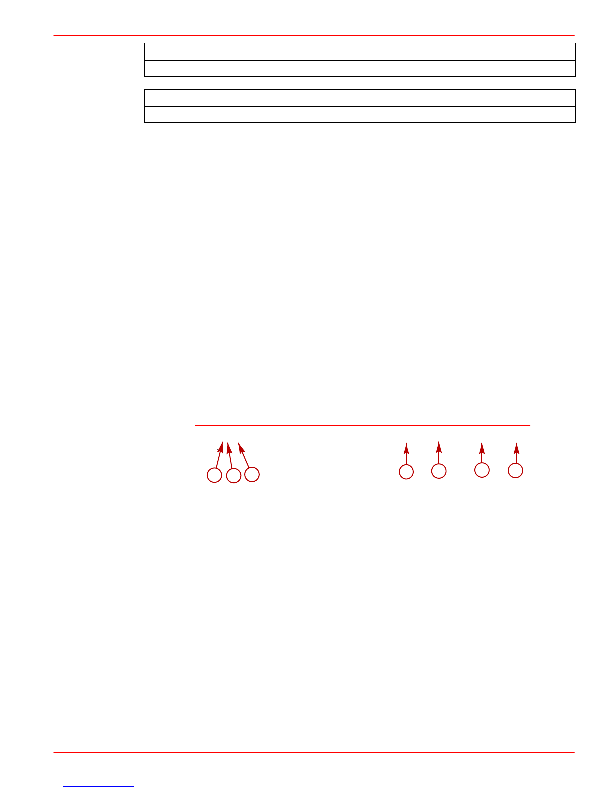
Page Numbering
Two number groups appear at the bottom of each page. The following is an example and
description.
Page 1A-3
a
a-Section Number
b-Section Part
c-Page Number
d-Manual Number
e-Revision Number 1
f-Month Printed
g-Year Printed
c
b
90-860074--1 FEBRUARY 2002
d
e
f
g
90-860074-–1 FEBRUARY 2002
Page 1A-3
Page 24
GENERAL INFORMATION
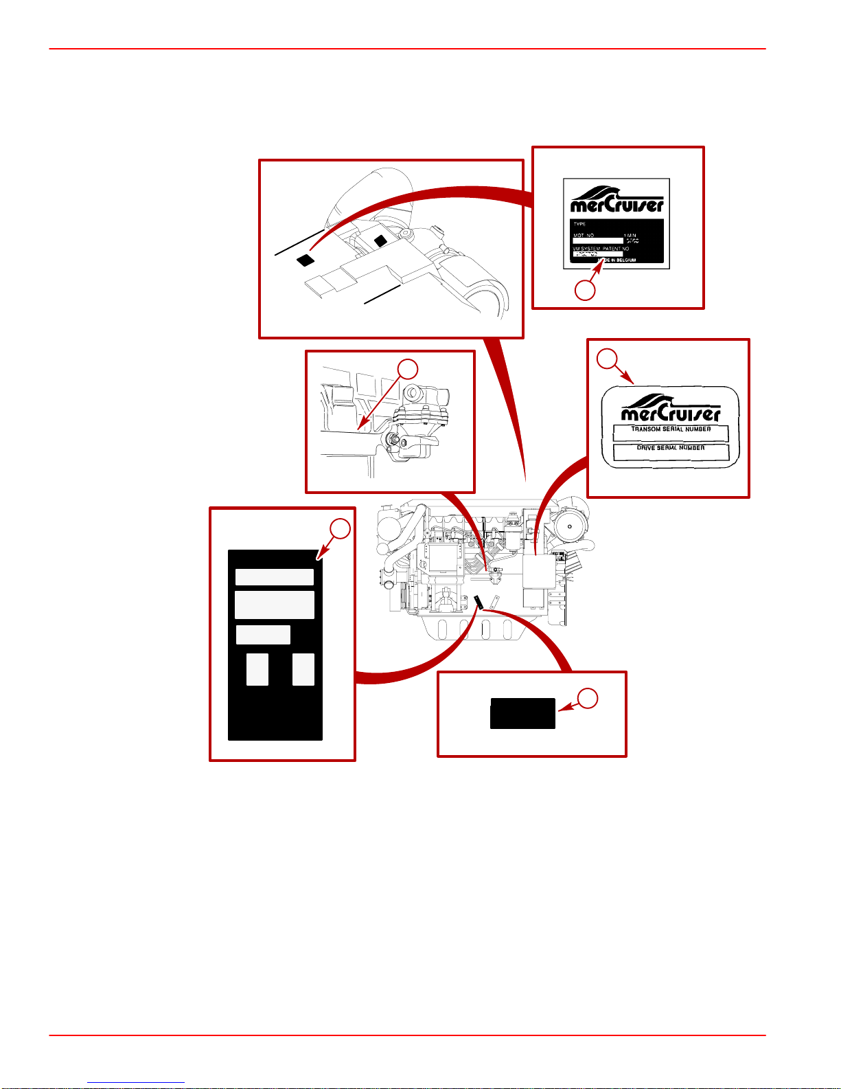
Engine Serial Number / Decal Locations
SERVICE MANUAL NUMBER 22
SERIAL NUMBER
H
P
L
B
K
W
K
G
MARINE POWER
EUROPE INC
MADE IN ITALY
MAX
RPM
a
75301
71675
d
b
7332
3
75388
73929
a
75298
BS
M12 11 3
O:
93_ _
c
71688
Typical Sterndrive (MCM) Engine Shown - Inboard (MIE) Similar
a-Serial Number Plate
b-Manufacturer’s Serial Number (Stamped in Block)
c-Exhaust Gas Emissions Certificate Number (Example)
d-MerCruiser Specification Decal
Page 1A-4
90-860064--1 FEBRUARY 2002
Page 25
SERVICE MANUAL NUMBER 22
Operation / Duty Cycle
It is the operator’s responsibility to operate within the following specified operational
capability, or duty cycle, as applicable to engine and installation:
NOTE:
Pleasure duty rating
recreation.
GENERAL INFORMATION
applies to recreational planing craft used exclusively for pleasure and
Light duty rating
applies to planing boats where the use of full rated power at maximum rated
rpm is limited (as stated above). Examples of Light Duty applications include, but are not
limited to: search and rescue craft, fast patrol boats, fire boats, dive boats, and limited
season fishing boats such as sport-fish charter boats. Application to common commercial
crafts having full-displacement or semi-displacement hulls exceeds the recommended
operational capability, or duty cycle.
IMPORTANT: Damage caused by improper application or failure to operate within the
operational capability, or duty cycle, will not be covered by the Mercury MerCruiser
Diesel Limited Warranty.
PLEASURE DUTY RATING / DUTY CYCLE
Specified Operating RPM Range 3600 - 3800
Wide Open Throttle (WOT)
Operation
LIGHT DUTY RATING / DUTY CYCLE
D2.8L D-Tronic and D4.2L D-Tronic
Limited to short periods of time.
D2.8L D-Tronic and D4.2L D-Tronic
Specified Operating RPM Range 3600-3800
Wide Open Throttle (WOT)
Operation
Continuous cruising RPM
Limited to less that 10% of operating time.
Limited to 90% or less of wide open throttle
RPM
Annual operating time Not to exceed 500 hours
90-860074-–1 FEBRUARY 2002
Page 1A-5
Page 26

GENERAL INFORMATION
Engine Break-In
Initial Break-In Procedure
The following procedure must be used on new and rebuilt diesel engines. This break-in
procedure allows the proper seating of the pistons and rings, which greatly reduces the
likelihood of problems.
IMPORTANT: It is recommended that the boat not be accelerated hard until this
procedure has been completed.
IMPORTANT: Never operate the starter motor longer than 15 seconds at a time, to
avoid overheating the starter motor. If engine does not start, wait 1 minute to allow
the starter motor to cool; then, repeat starting procedure.
1. Refer to appropriate Starting, Shifting and Stopping section in the Operation,
Maintenance and W arranty Manual provided with the product and start the engine. Allow
the engine to idle until it has reached normal operating temperature.
2. Operate the engine in gear for 3 minutes at each of the following rpms: 1200 rpm, 2400
rpm and 3000 rpm.
3. Operate the engine in gear for 3 minutes at each of the following rpms: 1500 rpm, 2800
rpm and 3400 rpm.
SERVICE MANUAL NUMBER 22
4. Operate the engine in gear for 3 minutes at each of the following rpms: 1800 rpm, 3000
rpm and WOT.
Page 1A-6
90-860064--1 FEBRUARY 2002
Page 27
SERVICE MANUAL NUMBER 22
GENERAL INFORMATION
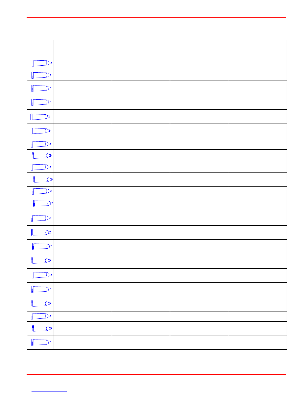
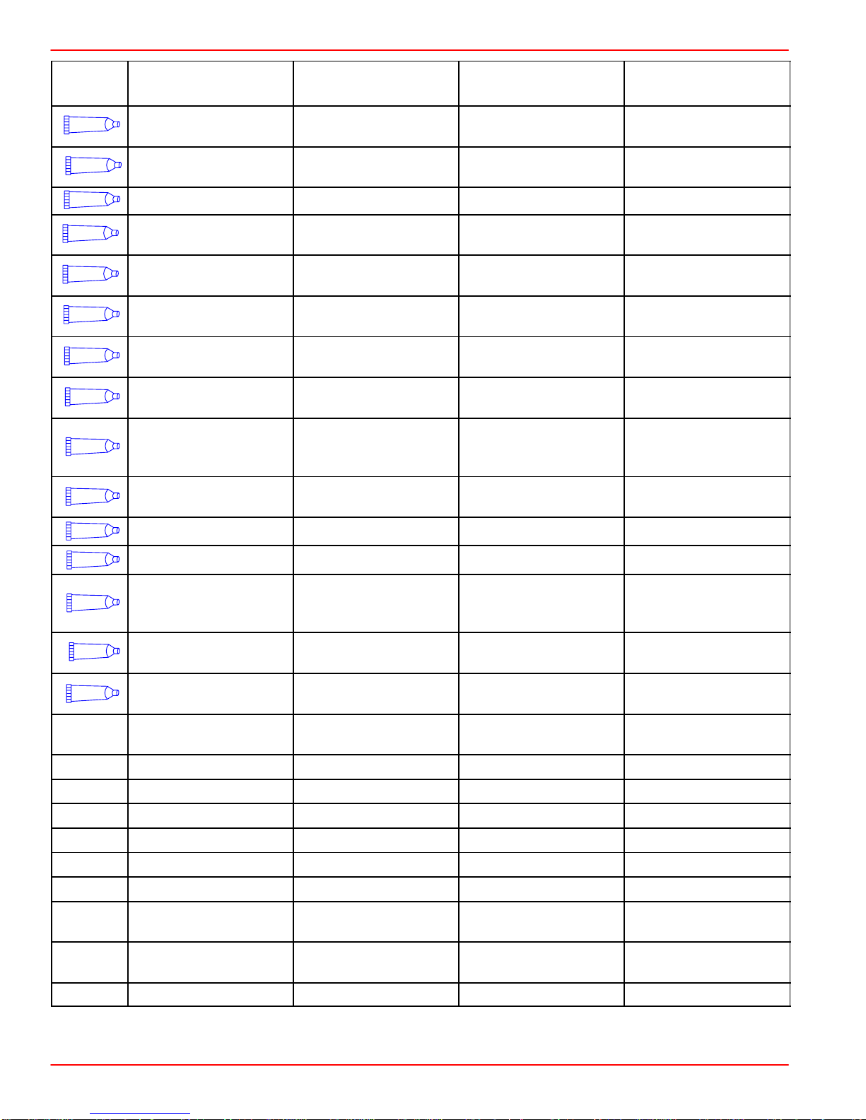
Mercury/Quicksilver Lubricants, Sealants And Adhesives
Tube
Ref. #
4
6
7
9
12
14
19
25
27
33
Description Container Size
Needle Bearing Assy.
Lubricant
8 oz (226.8 g) tube N/A 92-802868A1
Mercury Part
Number
Quicksilver Part
Number
Dielectric Grease 8 oz (226.8 g) can N/A 92-823506-1
Loctite 271 - Thread
Locker
Loctite 567 PST Pipe
Sealant
Loctite Master Gasket
Kit
2 Cycle Premium
Outboard Oil
10 ml tube N/A 92-809819
50 ml tube N/A 92-809822
N/A 92-12564-2
1 US qt (0.94 L) 92-802813A1 92-802813Q1
Perfect Seal 16 oz (0.45 kg) can N/A 92-34227-1
Liquid Neoprene 8 oz (226.8 g) can N/A 92-25711-3
Bellows Adhesive 1.5 oz (42.5 g) tube N/A 92-86166Q1
Loctite 680 Retaining
Compound
10 ml tube N/A 92-809833
51
66
94
95
110
114
34
82
91
79
87
42
Special Lubricant 101 8 oz (226.8 g) tube 92-802865A1 92-802865Q1
U-Joint and Gimbal
Bearing Grease
Loctite 222 Thread
Locker
Loctite 242 Thread
Locker
4 Cycle 25W40
Engine Oil
Premium Gear
Lubricant
High Performance
Gear Lube
Engine Coupler
Spline Grease
Anti-Corrosion
Grease
10 ml tube N/A 92-809818
10 ml tube N/A 92-809821
1 US qt (0.94 L) 92-802846A1 92-802846Q1
1 US qt (0.94 L) 92-802854A1 92-802854Q1
14 oz (0.39 kg)
cartridge
8 oz (226.8 g) tube 92-802867A1 92-802867Q1
92-802870A1 92-802870Q1
92-802837A1 92-802837Q1
92-802869A1 92-802869Q1
2-4-C with Teflon 8 oz (226.8 g) tube 92-802859A1 92-802859Q1
4 Stroke 10W30
Outboard Oil
Power Trim &
Steering Fluid
1 US qt (0.94 L) 92-802833A1 92-802833Q1
8 oz (226.8 g) 92-802880A1 92-802880Q1
90-860074-–1 FEBRUARY 2002
Page 1A-7
Page 28
GENERAL INFORMATION
SERVICE MANUAL NUMBER 22
Tube
Ref. #
115
116
117
118
119
120
121
122
123
124
Description Container Size
Premium Plus 2 Cycle
TC-W3 Outboard Oil
RTV 587 Silicone
Sealer
1 US qt (0.94 L) 92-802824A1 92-802824Q1
3 oz (85.05 g) N/A 92-809825
Mercury Part
Number
Quicksilver Part
Number
Loctite 7649 Primer N 4.5 oz (127.57 g) N/A 92-809824
Storage Seal Rust
Inhibitor
Corrosion Guard
15W40 4-cycle Diesel
Engine Oil
Extended Life
Antifreeze/Coolant
Marine Engine
Coolant
12 oz (325 ml) spray
can
12 oz (325 ml) spray
can
92-802878-56 92-802878Q56
92-802878 55 92-802878Q55
1.06 US gal.(4 L) 92-877695K1 92-877695Q1
1 US gal. (3.78 L) 92-877770K1 92-877770K1
1.33 US gal. (5 L) N/A 92-813054A2
Fuel System
Treatment and
16 oz (437 ml) 92-802876A1 92-802876Q1
Stabilizer Concentrate
Heat Transfer
Compound
1.5 oz (42.5 g) tube N/A 92-805701 1
125
126
127
128
129
Liquid Gasket N/A 92-808137
T442 Sealant N/A 92-862258
Loctite 5900 Ultra
Black RTV Silicone
13 oz (371 g) tube N/A 92-809826
Sealant
Loctite Gasket
Remover
Sealer Kit, Two Part
Epoxy
Dexron III Automatic
Transmission Fluid
18 oz (532 ml) spray
can
N/A 92-809828 1
N/A 92-65150 1
Obtain Locally Obtain Locally
Loctite 592 Obtain Locally Obtain Locally
Loctite Quick Tite Obtain Locally Obtain Locally
Isopropyl Alcohol Obtain Locally Obtain Locally
Hot Glue Obtain Locally Obtain Locally
Loctite 609 Obtain Locally Obtain Locally
Loctite 405 Obtain Locally Obtain Locally
Cyanacrylate
Adhesive
3M Permabond
#3M08155
Obtain Locally Obtain Locally
Obtain Locally Obtain Locally
Loctite 262 Obtain Locally Obtain Locally
Page 1A-8
90-860064--1 FEBRUARY 2002
Page 29

SERVICE MANUAL NUMBER 22
GENERAL INFORMATION
THIS PAGE IS INTENTIONALLY BLANK
90-860074-–1 FEBRUARY 2002
Page 1A-9
Page 30

GENERAL INFORMATION
SERVICE MANUAL NUMBER 22
THIS PAGE IS INTENTIONALLY BLANK
Page 1A-10
90-860064--1 FEBRUARY 2002
Page 31

SERVICE MANUAL NUMBER 22
MAINTENANCE
IMPORTANT INFORMATION
Section 1B - Maintenance
Table of Contents
Torque Specifications 1B-3. . . . . . . . . . . . . . . . . .
Special Tools 1B-3. . . . . . . . . . . . . . . . . . . . . . . . .
Tools 1B-3. . . . . . . . . . . . . . . . . . . . . . . . . . . . . . . .
Lubricants / Sealants / Adhesives 1B-3. . . . . . .
Engine Specifications 1B-4. . . . . . . . . . . . . . . . . .
Sterndrive (MCM) Engines 1B-4. . . . . . . . . . .
Inboard (MIE) Engines 1B-5. . . . . . . . . . . . . .
Capacities 1B-6. . . . . . . . . . . . . . . . . . . . . . . . . . . .
Engines 1B-6. . . . . . . . . . . . . . . . . . . . . . . . . . .
Drives 1B-6. . . . . . . . . . . . . . . . . . . . . . . . . . . . .
Transmissions 1B-6. . . . . . . . . . . . . . . . . . . . . .
Maintenance Schedules 1B-7. . . . . . . . . . . . . . . .
Maintenance Intervals 1B-7. . . . . . . . . . . . . . .
Sterndrive (MCM) Engines 1B-8. . . . . . . . . . .
Inboard (MIE) Engines 1B-11. . . . . . . . . . . . .
Engine External Views 1B-13. . . . . . . . . . . . . . . .
Starboard Side View 1B-13. . . . . . . . . . . . . . .
Front View 1B-14. . . . . . . . . . . . . . . . . . . . . . . .
Port Side View 1B-15. . . . . . . . . . . . . . . . . . . .
Rear View 1B-16. . . . . . . . . . . . . . . . . . . . . . . .
Engine Oil 1B-17. . . . . . . . . . . . . . . . . . . . . . . . . . .
Oil Level 1B-17. . . . . . . . . . . . . . . . . . . . . . . . . .
Changing Engine Oil and Oil Filter 1B-19. . .
Fuel 1B-21. . . . . . . . . . . . . . . . . . . . . . . . . . . . . . . .
Precautions 1B-21. . . . . . . . . . . . . . . . . . . . . . .
General Information 1B-22. . . . . . . . . . . . . . . .
Diesel Fuel In Cold Weather 1B-22. . . . . . . .
Fuel Filter 1B-23. . . . . . . . . . . . . . . . . . . . . . . .
Closed Cooling System 1B-28. . . . . . . . . . . . . . .
Coolant Requirement 1B-28. . . . . . . . . . . . . .
Checking Level 1B-29. . . . . . . . . . . . . . . . . . . .
Draining 1B-30. . . . . . . . . . . . . . . . . . . . . . . . . .
Filling 1B-32. . . . . . . . . . . . . . . . . . . . . . . . . . . .
Sacrificial Anodes 1B-33. . . . . . . . . . . . . . . . . . . .
Removal 1B-33. . . . . . . . . . . . . . . . . . . . . . . . .
Inspection 1B-33. . . . . . . . . . . . . . . . . . . . . . . .
Disassembly 1B-34. . . . . . . . . . . . . . . . . . . . . .
Reassembly 1B-34. . . . . . . . . . . . . . . . . . . . . .
Installation 1B-34. . . . . . . . . . . . . . . . . . . . . . . .
Flushing Seawater System 1B-35. . . . . . . . . . . .
SternDrive (MCM) Models 1B-35. . . . . . . . . .
Inboard (MIE) Models 1B-36. . . . . . . . . . . . . .
Inspect Water Pickups 1B-38. . . . . . . . . . . . . . . .
SternDrive Gear Housing 1B-38. . . . . . . . . . .
Inboard Though the Hull Pickup 1B-38. . . . .
Lubrication 1B-39. . . . . . . . . . . . . . . . . . . . . . . . . .
1
B
Throttle Cable 1B-39. . . . . . . . . . . . . . . . . . . . .
Shift Cable 1B-39. . . . . . . . . . . . . . . . . . . . . . . .
Engine Coupler / U-joint Shaft Splines 1B-40
U-joints 1B-41. . . . . . . . . . . . . . . . . . . . . . . . . . .
Drive Shaft Extension Models 1B-42. . . . . . .
Sterndrive Unit and Transom
Assembly 1B-42. . . . . . . . . . . . . . . . . . . . . . . .
Continuity Circuit 1B-43. . . . . . . . . . . . . . . . . . . . .
Continuity Circuit (continued) 1B-44. . . . . . . . . .
MerCathode 1B-45. . . . . . . . . . . . . . . . . . . . . . . . .
Engine Mounts 1B-45. . . . . . . . . . . . . . . . . . . . . . .
Electrical System 1B-45. . . . . . . . . . . . . . . . . . . . .
Power Steering 1B-46. . . . . . . . . . . . . . . . . . . . . .
Checking Fluid Level 1B-46. . . . . . . . . . . . . . .
Filling and Bleeding 1B-48. . . . . . . . . . . . . . . .
Transmission 1B-49. . . . . . . . . . . . . . . . . . . . . . . .
Checking Fluid Level 1B-49. . . . . . . . . . . . . . .
Power Trim 1B-50. . . . . . . . . . . . . . . . . . . . . . . . . .
Checking Fluid Level 1B-50. . . . . . . . . . . . . . .
Filling 1B-51. . . . . . . . . . . . . . . . . . . . . . . . . . . .
Gear Lube Monitor 1B-52. . . . . . . . . . . . . . . . . . .
Checking Fluid Level 1B-52. . . . . . . . . . . . . . .
Filling 1B-52. . . . . . . . . . . . . . . . . . . . . . . . . . . .
Seawater Strainer 1B-53. . . . . . . . . . . . . . . . . . . .
Air Filter 1B-54. . . . . . . . . . . . . . . . . . . . . . . . . . . . .
Removal 1B-54. . . . . . . . . . . . . . . . . . . . . . . . .
Inspection 1B-54. . . . . . . . . . . . . . . . . . . . . . . .
Cleaning 1B-55. . . . . . . . . . . . . . . . . . . . . . . . .
Installation 1B-55. . . . . . . . . . . . . . . . . . . . . . . .
Drive Belts 1B-56. . . . . . . . . . . . . . . . . . . . . . . . . .
General Information 1B-56. . . . . . . . . . . . . . . .
Inspection 1B-57. . . . . . . . . . . . . . . . . . . . . . . .
Engine Water Circulating Pump Belt 1B-57. .
Alternator Belt 1B-58. . . . . . . . . . . . . . . . . . . . .
Power Steering Pump Belt 1B-60. . . . . . . . . .
Vacuum Pump Belt 1B-62. . . . . . . . . . . . . . . .
Battery 1B-64. . . . . . . . . . . . . . . . . . . . . . . . . . . . . .
Charging System 1B-64. . . . . . . . . . . . . . . . . . . . .
Corrosion and Corrosion Protection 1B-64. . . . .
Saltwater Operation 1B-64. . . . . . . . . . . . . . . . . .
Freezing Temperature and Cold Weather
Operation 1B-65. . . . . . . . . . . . . . . . . . . . . . . . . . .
Cold Weather or Extended Storage 1B-66. . . . .
Power Package Layup 1B-66. . . . . . . . . . . . .
Draining 1B-67. . . . . . . . . . . . . . . . . . . . . . . . . .
Recommissioning 1B-73. . . . . . . . . . . . . . . . . . . .
90-860074--1 FEBRUARY 2002 Page 1B-1
Page 32

MAINTENANCE SERVICE MANUAL NUMBER 22
THIS PAGE IS INTENTIONALLY BLANK
Page 1B-2 90-860074--1 FEBRUARY 2002
Page 33

SERVICE MANUAL NUMBER 22
Torque Specifications
Description Nm lb-in. lb-ft
Rear Engine Mounts 51 38
Alternator Tensioning Or Mounting Bolt 28 21
Power Steering Tensioning Or Mounting Bolt 21 15
Vacuum Pump Tensioning Or Mounting Bolt 21 15
Heat Exchanger End Covers
MAINTENANCE
Special Tools
Tools
Upper 14-15
Lower 11
Description Part Number
Crankcase Oil Pump 90265A2
Flushing Attachment 44357T 2
Reference Electrode and Test Meter 91-76675T1
Description Part Number
Water Tap Hose Adapter To Water Inlet Fitting
Typical Hand-operated Grease Gun
120-
132
108-
120
Obtain Locally
Lubricants / Sealants / Adhesives
Description Part Number
Mercury Diesel Engine Oil 92-877695K1
Liquid Neoprene 92-25711--3
Loctite 567 PST Pipe Sealant 92-809822
Engine Coupler Spline Grease 92-816391A4
U-Joint and Gimbal Bearing Grease
2-4-C Marine Lubricant With Teflon 92-802861Q1
Exxon Unirex EP2 Grease Obtain Locally
SAE 30W Engine Oil Obtain Locally
1
Except on Bravo X Drive U-joint crosses and bearings - use Exxon Unirex EP2 Grease.
90-860074--1 FEBRUARY 2002 Page 1B-3
1
92-828052A2
Page 34

MAINTENANCE SERVICE MANUAL NUMBER 22
Engine Specifications
Sterndrive (MCM) Engines
Description
Crankshaft Kilowatts (Horsepower)
1
Propeller Shaft Kilowatts (Horsepower)
Engine Type
1
D2.8L D-Tronic D4.2L D-Tronic
123 ( 165 ) 186 ( 250 )
112 ( 150 ) 168 ( 225 )
In-Line 4 Cylinder
Diesel
In-Line 6 Cylinder
Diesel
Displacement 2.8 liter (169 cu. in.) 4.2 liter (254 cu. in.)
Firing Order 1 - 3 - 4 - 2 1 - 5 - 3 - 6 - 2 - 4
Bore 94 mm ( 3.700 in. )
Stroke 100 mm ( 3.937 in. )
Compression Ratio 16.5:1
Valve Clearance - Intake / Exhaust Hydraulic
Specification - Sterndrive (MCM)
Maximum Pressure Difference Between
Cylinders
500 kPa ( 72 psi )
Maximum High Idle No Load rpm 4200 ± 50
Governed rpm Setting (Begins At:) 3850 ± 50
Rated rpm at Wide-Open-Throttle
Low Idle rpm
2
3800
700
600
3
4
Oil Pres-
Oil Pressure:
Oil Temperature
750 rpm 1.5 - 3.1 bar [152-310 kPa] ( 22-45 psi )
3800 rpm 3.5 - 5.6 bar [345-556 kPa] ( 50-80 psi )
100 - 110 degrees C
( 212 - 230 degrees F )
Water: ( 2 Total )
70 degrees C ( 160 degrees F )
Thermostats:
1 at temperature:
1 at temperature: 82 degrees C ( 180 degrees F )
Oil: 95 degrees C ( 203 degrees F )
Coolant Temperature 80 - 85 degrees C ( 176 - 185 degrees F )
Electrical System 12-volt Negative ( – ) Ground
Alternator Rating 949W, 14.6v, 65 Amp.
Recommended Battery Rating 750 cca, 950 mca, or 180 Ah
Starter 12v, 2.7 kW
1 Power rated in accordance with NMMA Procedure - ISO 3046 (Technically Identical to ICOMIA
28-83).
2
Refer to Conditions Affecting Operation - Propeller Selection for additional information.
3
Mercury Serial Number 0L343084 and Below on D2.8L D-Tronic Engines. Mercury Serial Number
0L343703 and Below on D4.2L D-Tronic Engines.
4 Mercury Serial Number 0L343085 and Above on D2.8L D-Tronic Engines. Mercury Serial Number
0L343704 and Above on D4.2L D-Tronic Engines.
Page 1B-4 90-860074--1 FEBRUARY 2002
Page 35

SERVICE MANUAL NUMBER 22
Inboard (MIE) Engines
MAINTENANCE
Description
Crankshaft Kilowatts (Horsepower)
1
Propeller Shaft Kilowatts (Horsepower)
Engine Type
Displacement
1
D2.8L D-Tronic D4.2L D-Tronic
123 ( 165 ) 186 ( 250 )
119 ( 160 ) 179 ( 240 )
In-Line 4 Cylinder
Diesel
2.8 liter
169 cu. in.
In-Line 6 Cylinder
Diesel
4.2 liter (254 cu. in.)
Firing Order 1 - 3 - 4 - 2 1 - 5 - 3 - 6 - 2 - 4
Bore 94 mm ( 3.700 in. )
Stroke 100 mm ( 3.937 in. )
Compression Ratio 16.5:1
Valve Clearance - Intake / Exhaust Hydraulic
Specification - Inboard (MIE)
Maximum Pressure Difference Between
Cylinders
500 kPa ( 72 psi )
Maximum High Idle No Load rpm 4200 ± 50
Governed rpm Setting (Begins At:) 3850 ± 50
Rated rpm at Wide Open Throttle
Low Idle rpm
2
3800
700
600
3
4
Oil Pressure:
Oil Temperature
3800 rpm 3.5 - 5.6 bar ( 345-556 kPa ) [ 50-80 psi ]
100 - 110 degrees C
( 212 - 230 degrees F )
Water: ( 2 Total )
70 degrees C ( 160 degrees F )
750 rpm 1.5 - 3.1 bar ( 152-310 kPa ) [ 22-45 psi ]
Thermostats:
1 at temperature:
1 at temperature: 82 degrees C ( 180 degrees F )
Oil: ( 1 Total ) 95 degrees C ( 203 degrees F )
Coolant Temperature 80 - 85 degrees C ( 176 - 185 degrees F )
Electrical System 12-volt Negative ( – ) Ground
Alternator Rating 949W, 14.6v, 65 Amp.
Recommended Battery Rating 750 cca / 950 mca / 180 Ah
Starter 12v, 2.7 kW
1 Power rated in accordance with NMMA Procedure - ISO 3046 (Technically Identical to ICOMIA
28-83).
2
Refer to “Conditions Affecting Operation - Propeller Selection” for additional information.
3
Mercury Serial Number 0L343084 and Below on D2.8L D-Tronic Engines. Mercury Serial Number
0L343703 and Below on D4.2L D-Tronic Engines.
4
Mercury Serial Number 0L343085 and Above on D2.8L D-Tronic Engines. Mercury Serial Number
0L343704 and Above on D4.2L D-Tronic Engines.
90-860074--1 FEBRUARY 2002 Page 1B-5
Page 36

MAINTENANCE SERVICE MANUAL NUMBER 22
Capacities
NOTICE
All capacities are approximate fluid measures.
Engines
NOTICE
Unit Of Measurement: Liters (U.S. Quarts).
Drives
Total Oil Capacity
1
Model
D2.8L
D-Tronic
10 ( 8-1/2 ) 12 ( 12-3/4 )
D4.2L
D-Tronic
Oil Pan 8 ( 6-1/2 ) 10 ( 10-3/4 )
Oil Drainage
Oil Filter 1 ( 1 )
Oil Cooler 1 ( 1 )
Closed Cooling Circuit 11 ( 11-2/3 ) 13 ( 13-3/4 )
1
Always use dipstick to determine exact quantity of oil required
NOTICE
Unit Of Measurement: Liters (U.S. Quarts).
Item Specification
Bravo One 2.6 (2.75)
Drive Unit Oil Capacity (With Gear Lube
Monitor)
Bravo Two 3 (3.2)
Bravo
2.9 (3)
Three
Transmissions
IMPORT ANT: I t may be necessary to adjust oil levels depending on installation angle
and cooling systems (heat exchanger and fluid lines).
Unit Of Measurement: Liters (U.S. Quarts).
Make And Model Specification
Hurth 630A
1
Always use dipstick to determine exact quantity of oil required
Page 1B-6 90-860074--1 FEBRUARY 2002
630V
NOTICE
3 (3-1/4)
4 (4-1/2)
1
Fluid Type
Dexron III Automatic
Dexron III Automatic
Transmission Fluid
Page 37

SERVICE MANUAL NUMBER 22
For information and procedures on Troubleshooting refer to SECTION 1C.
Maintenance Schedules
NOTE: Refer to appropriate Mercury MerCruiser Sterndrive Service Manual for information
and procedures on sterndrive maintenance.
Avoid injury or death, product damage, fire or explosion. The electrical system is
capable of violent and damaging short circuits or severe electrical shocks. When
performing any activity where any electrical terminals could possibly be grounded
or touched, the battery cables should be disconnected at the battery.
Maintenance Intervals
Maintenance intervals and the tasks to be performed are generally based on an average
boating application and environment. However, individual operating habits and personal
maintenance preferences can have an impact on the suggested intervals. In consideration
of these factors, Mercury MerCruiser has adjusted some maintenance intervals and
corresponding tasks. In some cases, this may allow for more tasks to be performed in a
single visit to the dealer, rather than multiple visits. Therefore, it is very important that the
boat owner and servicing dealer discuss the Maintenance Schedule and develop
appropriate maintenance intervals to coincide with individual operating habits, the
environment and maintenance requirements.
MAINTENANCE
NOTICE
WARNING
90-860074--1 FEBRUARY 2002 Page 1B-7
Page 38

MAINTENANCE SERVICE MANUAL NUMBER 22
Sterndrive (MCM) Engines
Routine Maintenance *
Check crankcase oil (interval can be extended based on experience).
If operating in salt, brackish or polluted waters, flush cooling system after each use.
Drain any water from fuel filter after each use (If operating in freezing temperatures).
Check drive unit oil level, trim pump oil level and power steering
pump fluid level.
Check water pickups for debris or marine growth. Check water
strainer and clean. Check coolant level.
Inspect drive unit anodes and replace if 50 percent eroded.
Check battery connections and fluid level.
Lubricate propeller shaft and the retorque nut (if operating in only
freshwater, this maintenance may be extended to every four
months).
Operating in Saltwater Only: treat engine surface with corrosion
guard.
Clean air filter every 50 hours of operation.
Each
Day
Start
D
Each
Day
End
D
Weekly
D
D
D
D
Every
Two
Months
D
D
D
D
Ensure that the gauges and the wiring connections are secure.
Clean the gauges.
1
D
* Only perform maintenance which applies to your particular power package.
1
Or every 50 hours, whichever occurs first. If operating in saltwater, interval is reduced to every 25 hours or 30 days
whichever occurs first
Page 1B-8 90-860074--1 FEBRUARY 2002
Page 39

SERVICE MANUAL NUMBER 22
Sterndrive (MCM) Engines (Continued)
Scheduled Maintenance *
MAINTENANCE
After
First
20
hours
Annu-
ally
Every
100
hours or
Annually
Change crankcase oil and filter. D D
Touch-up paint power package
and spray with corrosion guard.
D
Change drive unit oil and
retorque connection of gimbal
ring to steering shaft.
Replace fuel filter(s). D
Check steering system and re-
mote control for loose, missing or
damaged parts. Lubricate cables
and linkages.
Inspect U-joints, splines, and
bellows. Check clamps. Check
engine alignment. Lubricate
U-joints and splines.
z
Every
200
hours
or 3
years
D
D
D
z
Every
300
hours
or 3
years
z
Every
2
years
Every
5
years
Every
500
hours
or 5
years
z
Every
1000
hours
or 5
years
z
Lubricate gimbal bearing and
engine coupler
*
D
Check continuity circuit for loose
or damaged connections. Test
MerCathodeR unit output on
D
Bravo Models.
Retorque engine mounts. D
Check electrical system for loose,
damaged or corroded fasteners.
D
* Only perform maintenance which applies to your particular power package.
z Whichever Occurs First
*
Lubricate engine coupler every 50 hours if operated at idle for prolonged periods of time.
90-860074--1 FEBRUARY 2002 Page 1B-9
Page 40

MAINTENANCE SERVICE MANUAL NUMBER 22
Sterndrive (MCM) Engines (Continued)
Scheduled Maintenance * (Continued)
Lubricate drive shaft U-joints and
tailstock input and output
bearings.
Inspect condition and tension of
belts.
Check cooling system and exhaust system hose clamps for
tightness Inspect both systems
for damage or leaks.
Disassemble and inspect seawater pump and replace worn components.
Clean seawater section of closed
cooling system. Clean, inspect
and test pressure cap. Check
anodes.
After
First
20
hours
Annu-
ally
Every
100
hours or
Annually
z
D
D
D
D
D
Every
200
hours
or 3
years
z
Every
300
hours
or 3
years
z
Every
2
years
Every
5
years
Every
500
hours
or 5
years
z
Every
1000
hours
or 5
years
z
Replace coolant. D
Replace air filter. D
Clean aftercooler core. D
Clean fuel tank. D
* Only perform maintenance which applies to your particular power package.
z Whichever Occurs First
Page 1B-10 90-860074--1 FEBRUARY 2002
Page 41

SERVICE MANUAL NUMBER 22
Inboard (MIE) Engines
Routine Maintenance *
MAINTENANCE
Check crankcase oil (interval can be extended based on experi-
Each
Day
Start
D
Each
Day
End
Weekly
Every
Two
Months
ence).
If operating in salt, brackish or polluted waters, flush cooling sys-
tem after each use.
Drain any water from fuel filter after each use (if operating in
freezing temperatures).
D
D
Check transmission fluid. D
Check water pickups for debris or marine growth. Check water
strainer and clean. Check coolant level.
D
Check battery connections and fluid level. D
Clean air filter every 50 hours of operation. D
Operating in Saltwater Only: treat engine surface with corrosion
guard.
Ensure that the gauges and the wiring connections are secure.
Clean the gauges.
1
D
D
* Only perform maintenance which applies to your particular power package.
1
Or every 50 hours, whichever occurs first. If operating in saltwater, interval is reduced to every 25 hours or 30 days
whichever occurs first
90-860074--1 FEBRUARY 2002 Page 1B-11
Page 42

MAINTENANCE SERVICE MANUAL NUMBER 22
Inboard (MIE) Engines (Continued)
Scheduled Maintenance *
Every
200
hours
or 3
years
z
Every
years
After
First
20
hours
Annu-
ally
Every
100
hours or
Annually
z
Change crankcase oil and filter. D D
Touch-up paint power package and
spray with corrosion guard.
D
Change transmission fluid. D
Replace fuel filter(s). D
Check steering system and remote
control for loose, missing or damaged
D
parts. Lubricate cables and linkages.
Retorque engine mounts. D
Check electrical system for loose, dam-
aged or corroded fasteners.
D
Inspect condition and tension of belts. D
Check cooling system and exhaust sys-
tem hose clamps for tightness. Inspect
D
both systems for damage or leaks.
Disassemble and inspect seawater
pump and replace worn components.
D
Clean seawater section of closed cooling
system. Clean, inspect and test pressure
D
cap. Check anodes on diesel models.
Replace coolant. D
Every
500
hours
2
or 5
years
z
Every
1000
hours
or 5
years
z
Per
OEM
Replace air filter. D
Clean aftercooler core. D
Clean fuel tank. D
Check engine-to-propeller shaft align-
ment.
* Only perform maintenance which applies to your particular power package.
z Whichever Occurs First
Page 1B-12 90-860074--1 FEBRUARY 2002
D
Page 43

SERVICE MANUAL NUMBER 22
Engine External Views
Starboard Side View
1
MAINTENANCE
7
2
3
4
5
6
8
9
15
14
13
Typical In-Line D-Tronic Diesel
1-Exhaust Riser, or Elbow If Equipped
2-Intercooler Air Duct
3-Fluid Cooler
4-Shift Plate
5-Intercooler
6-Sacrificial Anode
7-Power Steering Fluid Reservoir
8-Thermostat Housing
9-Heat Exchanger
10 - Engine Oil Cooler
11 - Power Steering Pump
12 - Front Engine Mount
13 - Oil Pan
14 - Starter Motor
15 - Wastegate
10
11
12
78409
90-860074--1 FEBRUARY 2002 Page 1B-13
Page 44

MAINTENANCE SERVICE MANUAL NUMBER 22
Front View
16
15
14
13
12
11
1
2
3
4
5
6
7
10
8
9
78310
Typical In-Line D-Tronic Diesel
1-Sacrificial Anode
2-Pressure Cap
3-Heat Exchanger
4-Engine Oil Cooler
5-Seawater Pump Outlet Hose
6-Alternator
7-Seawater Pump Inlet Hose
8-Seawater Pump
9-Oil Pan
10 - Crankshaft Pulley
11 - Engine Water Circulating Pump Pulley
12 - Power Steering Pump
13 - Front Engine Mount
14 - Oil Thermostat
15 - Oil Filter
16 - Exhaust Elbow
Page 1B-14 90-860074--1 FEBRUARY 2002
Page 45

SERVICE MANUAL NUMBER 22
Port Side View
MAINTENANCE
19
20
18
17
16
1
2
3
4
6
5
7
8
9
11
15
12
13
14
10
75298
Typical In-Line D-Tronic Diesel
1-Oil Fill Cap
2-Engine Cover
3-Fuel Injector
4-Fuel Filter
5-Gear Lube Monitor
6-PCV / Oil Separator
7-Air Filter
8-MerCathode Controller
9-Rear Engine Mount
10 - Flywheel Housing (Rear Portion)
11 - 5 Amp. ECM Fuse
12 - Electrical Box
13 - Engine Block Ground Stud
14 - Fuel Delivery Pump
15 - Oil Pan
16 - Engine Control Module (ECM)
17 - Throttle Position Sensor
18 - Vibration Damper And Crankshaft Pulley
19 - Seawater Pump
20 - Heat Exchanger
90-860074--1 FEBRUARY 2002 Page 1B-15
Page 46

MAINTENANCE SERVICE MANUAL NUMBER 22
Rear View
1
2
3
7
4
5
6
74305
Typical In-Line D-Tronic Diesel
1-Air Filter
2-Turbocharger
3-Exhaust Elbow
4-Rear Engine Mount
5-Engine Coupler
6-Flywheel Housing (Rear Portion)
7-Electrical Box
Page 1B-16 90-860074--1 FEBRUARY 2002
Page 47

SERVICE MANUAL NUMBER 22
Engine Oil
ENVIRONMENTAL HAZARD! Discharge of oil or oil waste into the environment is
restricted by law. Do NOT spill oil or oil waste into the environment when using or
servicing your boat. Contain and dispose of oil or oil waste as defined by local
authorities.
To help obtain optimum engine performance and to provide maximum protection, the engine
requires engine oil with a rating of HD-SAE-API CG-4 and CH-4.
We strongly recommend the use of:
MERCURY DIESEL ENGINE OIL QUICKSILVER HEAVY DUTY ENGINE OIL
These oils are both specially blended 15W-40 oil with Marine Additives, for all temperature
operation. They both exceed requirements for API CH-4, CF-4, CG-4 and CF-2 oils.
Other recommended oils:
SHELL MYRINA TEXACO URSA SUPER TD VEEDOL TURBOSTAR
MOPAR WINTERSHALL MULTI-REKORD WINTERSHALL VIVA 1
MAINTENANCE
CAUTION
These oils are approved by Mercury Marine and Marine Power Europe. For all temperature
operation use 15W-40 oil.
Oil Level
OVERFILLED ENGINE CRANKCASE
An overfilled crankcase can cause a fluctuation or drop in oil pressure on Mercury
MerCruiser engines. The over-full condition results in the engine crankshaft splashing and
agitating the oil, causing it to become aerated. The aerated oil causes a loss of engine
performance and an increase in crankcase backpressure. An extreme overfill condition
could result in large amounts of oil being drawn into the intake.
Care must be taken when checking engine oil level. Oil level must be maintained between
the minimum oil level mark and the maximum mark on the dipstick. To ensure that you are
not getting a false reading, observe the following before checking the oil level.
• Boat at rest in the water, or if boat is on a trailer, raise or lower bow until the boat is
setting like it does at rest in the water.
• Allow ten minutes for oil to drain into the oil pan if engine has just been operated or
oil has just been added.
90-860074--1 FEBRUARY 2002 Page 1B-17
Page 48

MAINTENANCE SERVICE MANUAL NUMBER 22
CHECKING / FILLING
IMPORTANT: Engine crankcase oil must be checked at intervals specified in
Maintenance Schedule. It is normal for an engine to use a certain amount of oil in the
process of lubricating and cooling the engine. The amount of oil consumed is greatly
dependent upon engine speed, with consumption being highest at WOT and
decreasing substantially as engine speed is reduced.
5. Check engine oil daily before first start-up.
CAUTION
Avoid possible injury, or damage to oil dipstick and internal engine components.
Do NOT remove crankcase oil dipstick when engine is running. Stop the engine
completely before removing or inserting dipstick.
If it becomes necessary to check oil level during operation, stop the engine and allow
approximately 10 minutes for oil to drain into pan.
6. Remove oil dipstick. Wipe clean and install into dipstick tube.
7. Remove dipstick and observe oil level. Oil must be between marks on dipstick.
a
a-Oil Dipstick
71382
c
71380
b
75732
b-Minimum Oil Level Mark
c-Maximum Oil Level Mark
8. If oil level is low, remove oil filler cap. Add specified oil to bring level up to, but not over,
maximum oil level mark on dipstick.
a
a-Oil Filler Cap
9. Install oil filler cap.
Page 1B-18 90-860074--1 FEBRUARY 2002
75301
Page 49

SERVICE MANUAL NUMBER 22
Changing Engine Oil and Oil Filter
IMPORTANT: Change oil when engine is warm from operation. Warm oil flows more
freely, carrying away more impurities. Use only recommended engine oil (see
Specifications).
1. Start engine and allow it to reach normal operating temperature.
2. Stop the engine and allow approximately 10 minutes for oil to drain into oil pan.
3. Remove threaded fitting from crankcase oil drain hose.
4. Install crankcase oil pump (90265A2) onto threaded fitting of oil drain hose.
MAINTENANCE
b
a
c
a-Oil Drain Hose
b-Threaded Fitting
c-Crankcase Oil Pump
5. Pump oil out of crankcase into drain pan.
6. Remove crankcase oil pump.
7. Install threaded fitting on crankcase oil drain hose.
b
a
70571
75298
90-860074--1 FEBRUARY 2002 Page 1B-19
Page 50

MAINTENANCE SERVICE MANUAL NUMBER 22
8. Remove and discard oil filter and seal.
9. Coat seal on new filter with engine oil and install filter. Hand tighten only, do NOT use
a filter wrench.
b
bb
a
75297
a-Oil Filter
b-Seal
10. Remove oil fill cap and refill engine with new engine oil.
CAUTION
Do NOT overfill the engine with oil. Too much engine oil will cause a loss of engine
performance and an increase in crankcase back-pressure.
11. Add specified oil to bring level up to, but not over, maximum oil level mark on dipstick.
12. Install oil filler cap.
13. Supply cooling water to water inlet.
14. Start the engine and allow it to reach normal operating temperature.
IMPORTANT: Always use dipstick to determine how much oil is required.
CAUTION
Avoid possible injury or damage to oil dipstick and internal engine components. Do
NOT remove crankcase oil dipstick when engine is running. Stop the engine
completely before removing or inserting dipstick.
15. Stop engine and allow approximately 10 minutes for oil to drain into oil pan.
16. Remove dipstick and observe oil level. Oil must be between the marks on the dipstick.
17. Start engine and check for leaks.
Page 1B-20 90-860074--1 FEBRUARY 2002
Page 51

SERVICE MANUAL NUMBER 22
Fuel
Precautions
Always disconnect battery cables from battery BEFORE working on fuel system to
prevent fire. This eliminates the engine wiring as a potential source of ignition.
FIRE HAZARD: Fuel leakage from any part of the fuel system can be a fire hazard
which can cause serious bodily injury or death. Careful periodic inspection of entire
fuel system is mandatory , particularly after storage. All fuel components including
fuel tanks - whether plastic, metal or fiberglass - fuel lines, primers, fittings and fuel
filters should be inspected for leaks, softening, hardening, swelling or corrosion.
Any sign of leakage or deterioration requires replacement before further engine
operation.
Electrical system components on this engine are not external ignition protected.
DO NOT STORE OR UTILIZE GASOLINE ON BOATS EQUIPPED WITH THESE
ENGINES, UNLESS PROVISIONS HAVE BEEN MADE TO EXCLUDE GASOLINE
VAPORS FROM ENGINE COMPARTMENT (REF: 33 CFR). Failure to comply could
result in fire, explosion and/or severe personal injury.
MAINTENANCE
WARNING
WARNING
WARNING
IMPORTANT: Use of improper or water contaminated diesel fuel can cause serious
engine damage. Use of improper fuel is considered misuse of engine, damage
caused thereby will not be covered by warranty.
WARNING
Under no circumstances should gasoline, gasohol and/or alcohol be mixed with
diesel fuel for any reason. This mixture of gasoline, gasohol and/or alcohol with
diesel fuel is highly flammable and produces a significant risk to the user.
90-860074--1 FEBRUARY 2002 Page 1B-21
Page 52

MAINTENANCE SERVICE MANUAL NUMBER 22
General Information
Grade 2-D diesel fuel is required, meeting ASTM Standards D975 (or fuel rated Diesel DIN
51601) and having a minimum cetane rating of 45.
The cetane number is a measure of the ignition quality of diesel fuel. Increasing the cetane
number will not improve overall engine performance, but it may be necessary to raise the
cetane rating for low temperature or high altitude use. A lower cetane number could cause
hard starting and slower warm-up and could increase engine noise and exhaust emissions.
NOTE: If your engine suddenly becomes noisy after a fuel fill, you may have received
substandard fuel with a low cetane rating.
CAUTION
Avoid fuel system damage. Use of fuels not recommended by Mercury MerCruiser
may cause hard-starting and other various troubles such as premature wear of the
injection pump plungers and injection nozzles resulting from the deposit of carbon
residue and other contaminants.
Sulphur content of the above fuel is rated at 0.50% by weight, maximum (ASTM). Limits may
vary in countries outside of the United States.
On intermittent use engines, high sulphur content diesel fuel will greatly increase:
• Corrosion on metal parts.
• Deterioration of elastomer and plastic parts.
• Corrosion and extensive damage, and excessive wear of internal engine parts,
particularly bearings.
• Starting and operating difficulties.
Diesel Fuel In Cold Weather
Unaltered diesel fuels thicken and gel in cold temperatures unless treated. Virtually all diesel
fuels are climatized to allow their use in the particular region for that time of the year. It is
the owner/operator’s responsibility, if it becomes necessary, to further treat diesel fuel, by
adding a commercial standard brand anti-gel diesel fuel additive. Follow product directions.
Page 1B-22 90-860074--1 FEBRUARY 2002
Page 53

SERVICE MANUAL NUMBER 22
Fuel Filter
PRECAUTIONS
Be careful when draining, filling or replacing water separating fuel filter; diesel fuel
is flammable. Ensure that the ignition key is OFF. Do NOT smoke or allow sources
of open flame in the area while changing fuel system components. Wipe up any
spilled fuel immediately. Do NOT allow fuel to come into contact with any hot surface which may cause it to ignite.
Dispose of fuel-soaked rags, paper, etc., in an appropriate air tight, fire retardant
container. Fuel-soaked items may spontaneously ignite and result in a fire hazard
which could cause serious bodily injury or death.
Make sure no fuel leaks exist before closing engine hatch.
Absolute cleanliness is required for work on the fuel injection system, since the
injection pump and fuel injectors have very close tolerances. Even minute particles
of dirt or small amounts of water can impair the function of the fuel injection system.
MAINTENANCE
WARNING
WARNING
WARNING
CAUTION
90-860074--1 FEBRUARY 2002 Page 1B-23
Page 54

MAINTENANCE SERVICE MANUAL NUMBER 22
DRAINING
NOTICE
Refer to Precautions BEFORE proceeding.
The filter can be drained of water and small dirt particles by opening the water drain cap
(bleed valve).
IMPORTANT: To ensure complete draining, in warm weather, open the drain cock
before starting daily operations. In cold weather, when there is a possibility that the
condensed water will freeze, drain the filter shortly after the end of daily operations.
NOTE: Place a suitable container under fuel filter to catch contaminated fuel and/or water
1. Using a suitable container to catch contaminated fuel and/or water, open drain cap at
bottom of filter by turning the drain counterclockwise (as viewed from the bottom
of the
filter).
2. Drain until fuel is clear in appearance.
a
a-Fuel Filter
b-Drain Cap
3. Close drain by turning clockwise.
4. Fill fuel filter as outlined in Filling.
b
74726
Page 1B-24 90-860074--1 FEBRUARY 2002
Page 55

SERVICE MANUAL NUMBER 22
FILLING
Refer to Precautions BEFORE proceeding.
Follow this procedure after installing a new filter or if fuel has been completely drained from
the filter checking for water.
NOTE: Place a suitable container under fuel filter to catch contaminated fuel and/or water
1. Loosen bleed screw on fuel filter bracket.
2. Move plunger knob on pump/primer up and down repeatedly, until an air free stream of
fuel flows from bleed screw. Filter is full when this occurs.
MAINTENANCE
NOTICE
a
b
75301
a-Plunger Knob
b-Bleed Screw
3. Securely tighten bleed screw.
4. Supply cooling water to water inlet.
5. Start the engine, check for fuel leaks. If leaks exist stop engine immediately. Recheck
filter installation.
90-860074--1 FEBRUARY 2002 Page 1B-25
Page 56

MAINTENANCE SERVICE MANUAL NUMBER 22
REMOVAL
NOTICE
Refer to Precautions BEFORE proceeding.
NOTE: Place a suitable container under fuel filter to catch contaminated fuel and/or water
1. Twist locking ring by hand. Remove water separating fuel filter and sealing ring from
mounting bracket. Do NOT use a filter wrench.
a
b
70161
a-Locking Ring
b-Filter Element
IMPORTANT: Element cannot be cleaned and reused. It must be replaced.
2. Remove the drain cap and O-ring from bottom of the existing filter. Note position of
O-ring seal.
3. Inspect and replace damaged components.
75579
Page 1B-26 90-860074--1 FEBRUARY 2002
Page 57

SERVICE MANUAL NUMBER 22
INSTALLATION
1. Install O-ring and drain cap on new filter.
MAINTENANCE
a
b
70160
a-O-ring Seal
b-Drain Cap
2. Lubricate seal with clean engine oil.
3. Align filter to bracket. Twist locking ring by hand to secure filter to bracket. Do NOT use
a filter wrench.
a
b
c
a-Filter Header
b-Locking Ring
c-Seal
d-Fuel Filter
4. Fill fuel filter as previously outlined.
90-860074--1 FEBRUARY 2002 Page 1B-27
d
74731
Page 58

MAINTENANCE SERVICE MANUAL NUMBER 22
Closed Cooling System
Coolant Requirement
CAUTION
Alcohol or methanol based anti-freeze or plain water are not recommended for use
in the closed cooling section of cooling system at any time.
Because diesel engines are high compression engines and related higher engine operating
temperatures are created, the closed cooling system and engine must remain as clean as
possible to provide adequate engine cooling. This can only be assured by using the proper
anti-freeze, water, additives and inhibitors. It is recommended that the closed cooling
section of the cooling system be filled with a low silicate formula of ethylene glycol
anti-freeze in solution with deionized water. A low silicate formula prevents anti-freeze
separation, which causes a silicate gelatin to form. This gelatin will block engine and heat
exchanger passages causing engine overheating.
The coolant, if not premixed, should be mixed before being added to the closed cooling
system using anti-freeze and deionized water. Common tap water or softened water
contains unwanted minerals, which can leave large deposits in the system restricting the
cooling system efficiency. In addition, additives and inhibitors introduced into acceptable
coolant solutions will form a protective film on internal passages and provide protection
against internal cooling system erosion.
The closed cooling section should be kept filled year-round with an acceptable coolant
solution. Do NOT drain closed cooling section for storage, this will promote rusting of
internal surfaces. If engine will be exposed to freezing temperatures, ensure that closed
cooled section is filled with a properly mixed anti-freeze/coolant solution to protect engine
and closed cooling system to lowest temperature to which they will be exposed.
IMPORTANT: The anti-freeze/coolant used in these marine engines must be a low
silicate ethylene glycol, containing special additives and deionized, purified water.
Using other types of engine coolant may cause fouling of the heat exchangers and
overheating of the engine. Do NOT combine different types of coolants without
knowing that they are compatible. Refer to the coolant manufacturer’s instructions.
Some acceptable types of anti-freeze/coolants are listed in the following table. Refer to
Maintenance Schedules for change intervals.
Description
Premixed Marine Engine Coolant 92-813054A2
Fleetguard Compleat (Product 91-50663 with DCA4 additive) Obtain Locally
Part Number
Page 1B-28 90-860074--1 FEBRUARY 2002
Page 59

SERVICE MANUAL NUMBER 22
Checking Level
1. Coolant level must be between the bottom ADD mark and top FULL Hot mark on coolant
recovery bottle with the engine at normal operating temperature.
2. Add specified coolant to the coolant recovery bottle as required.
MAINTENANCE
a
c
b
72520
a-Coolant Recovery Reservoir
b-Bottom ADD Mark
c-Top FULL Hot Mark
WARNING
Allow engine to cool before removing pressure cap. Sudden loss of pressure could
cause hot coolant to boil and discharge violently causing severe injury.
3. Remove pressure cap.
4. Coolant level must be to the bottom edge of the fill neck with the engine cool.
a
75299
a-Fill Neck
5. If coolant is low, check the coolant system for malfunction.
IMPORTANT: When installing pressure cap, tighten it until it contacts locking tabs on
filler neck.
6. Install pressure cap.
90-860074--1 FEBRUARY 2002 Page 1B-29
Page 60

MAINTENANCE SERVICE MANUAL NUMBER 22
Draining
NOTICE
For instructions on Draining Seawater Section refer to Cold Weather or Extended Storage
in this SECTION 1B.
IMPORTANT: Observe the following:
w Insert a wire into drain holes to ensure that foreign material is not obstructing
the drain holes.
w Ensure engine is as level as possible to promote complete draining of cooling
system.
w Closed cooled section must be kept filled year round with recommended
coolant. If engine will be exposed to freezing temperatures, make sure closed
cooled section is filled with an ethylene glycol anti-freeze and water solution
properly mixed to protect engine to lowest temperature to which it will be
exposed.
w Do NOT use Propylene Glycol anti-freeze in the closed cooled section of the
engine.
WARNING
Allow engine to cool before removing pressure cap. Sudden loss of pressure could
cause hot coolant to boil and discharge violently causing severe injury.
1. Allow engine to cool. After engine has cooled, turn cap 1/4 turn to allow any pressure
to escape slowly, then push down and turn cap all the way off of heat exchanger/coolant
tank.
NOTE: Drain coolant into a suitable container. Dispose of old coolant properly.
2. Drain coolant from intake/exhaust manifold by opening the drain valves.
a
Typical
a-Intake/Exhaust Manifold Drain Valve
Page 1B-30 90-860074--1 FEBRUARY 2002
71364
Page 61

SERVICE MANUAL NUMBER 22
3. –Drain coolant from the engine block by opening the drain valve.
Typical
4. After coolant has drained completely, securely close drain valves.
MAINTENANCE
a
76391
a-Engine Block Drain Valve
5. Empty the coolant recovery bottle.
6. If required, clean the closed cooled system. Refer to SECTION 6A.
7. Fill system with required coolant, as outlined in Filling.
90-860074--1 FEBRUARY 2002 Page 1B-31
Page 62

MAINTENANCE SERVICE MANUAL NUMBER 22
Filling
1. Slowly fill with coolant through heat exchanger fill neck.
2. Continue filling until coolant level is at bottom of fill neck.
CAUTION
Overheating from insufficient cooling water will cause engine and drive system
damage. Ensure that there is sufficient water always available at water inlet during
operation.
3. Supply cooling water to water inlet.
4. With the pressure cap off, start the engine and run at fast idle (1500-1800 rpm). Add
coolant to heat exchanger, as required, to maintain coolant level 1 in. (25 mm) below
fill neck.
5. After engine has reached normal operating temperature (thermostats are fully open),
and coolant level remains constant, fill heat exchanger to bottom of fill neck.
6. Install pressure cap.
7. Observe engine temperature gauge to make sure that engine operating temperature is
normal. If gauge indicates excessive temperature, stop engine immediately and
examine for cause.
8. Remove cap from coolant recovery bottle and fill to a level between the ADD and FULL
marks with coolant solution. Reinstall cap.
9. With engine still operating, check hose connections, fittings and gaskets for leaks.
Page 1B-32 90-860074--1 FEBRUARY 2002
Page 63

SERVICE MANUAL NUMBER 22
Sacrificial Anodes
Sacrificial anode locations:
• Starboard, aft-side of the heat exchanger.
• Top of the intercooler end cover.
Removal
1. Allow the engine to cool.
2. Remove anode plugs and sacrificial anodes.
MAINTENANCE
Inspection
b
c
73327
a-Heat Exchanger
b-Intercooler End Cover
c-Anode Plug And Sacrificial Anode
1. Replace anode assembly when deteriorated 50%.
• Length When New - 19 mm (3/4 in.)
• Diameter When New - 16 mm (5/8 in.)
2. Discard sealing washer.
a
c
73326
a-Anode Plug
b-Sacrificial Anode
c-Length
d-Diameter
e-Sealing Washer
90-860074--1 FEBRUARY 2002 Page 1B-33
c
e
d
b
a
71368
Page 64

MAINTENANCE SERVICE MANUAL NUMBER 22
Disassembly
NOTE: Sacrificial anodes are available as an assembly. Replace both the plug and anode,
if so desired.
1. Unscrew sacrificial anode from anode plug by holding plug hex head and turning anode.
Reassembly
b
a
71367
a-Plug
b-Anode
1. Clean interior threads of anode plug.
2. Apply Loctite Pipe Sealant with Teflon to threads of new sacrificial anode and install into
anode plug. Tighten securely.
b
a
71367
a-Plug
b-Anode
Installation
1. Install new sealing washer.
2. Install anode plug, with sacrificial anode and washer into heat exchanger or intercooler
end cover. Tighten securely.
b
a
71368
a-Plug And Anode
b-Sealing Washer
3. Fill closed cooled system with required coolant, as outlined in Filling.
Page 1B-34 90-860074--1 FEBRUARY 2002
Page 65

SERVICE MANUAL NUMBER 22
Flushing Seawater System
If engine is operated in salty, polluted or mineral-laden water, flush seawater section of
cooling system (preferably after each use) to reduce corrosion and prevent the
accumulation of deposits in the system. Thoroughly flush seawater section prior to storage.
SternDrive (MCM) Models
When flushing, be certain the area around propeller is clear and no one is standing
nearby. To avoid possible injury, remove propeller.
1. Install Flushing Attachment (or equivalent) over water pickup openings in gear housing.
2. Attach a hose between the flushing attachment and a water source.
MAINTENANCE
WARNING
a
b
a-Flushing Attachment
b-Hose
3. Lower sterndrive unit to full DOWN/IN position.
72012
CAUTION
Do NOT run engine above 1500 rpm when flushing. Suction created by seawater
pickup pump may collapse flushing hose, causing engine to overheat.
4. Partially open water tap (approximately 1/2 maximum capacity). DO NOT use full water
pressure.
5. Place remote control in NEUTRAL, IDLE speed position and start engine.
6. Operate engine at IDLE speed in NEUTRAL for 10 minutes, then stop engine.
7. Shut off water tap.
8. If boat is in the water, raise sterndrive unit to TRAILER position.
9. Remove hose and flushing attachment.
90-860074--1 FEBRUARY 2002 Page 1B-35
Page 66

MAINTENANCE SERVICE MANUAL NUMBER 22
Inboard (MIE) Models
WARNING
When flushing, be certain the area around propeller is clear , and no one is standing
nearby. To avoid possible injury, remove propeller.
CAUTION
If boat is in the water, seacock (water inlet valve), if equipped, must be closed until
engine is to be re-started, to prevent water from flowing into the boat and/or back
into the cooling system. If boat is not fitted with a seacock, water inlet hose must
be disconnected and plugged (to prevent water from flowing into the boat and/or
back into the cooling system). As a precautionary measure, attach a tag to the
ignition switch or steering wheel of the boat with the warning: Open seacock or
reconnect water inlet hose before starting engine.
1. If the boat is in the water, close the seacock, if equipped, or plug the seawater inlet hose
to prevent seawater from entering the boat.
2. Disconnect the seawater inlet hose from the seawater pump connector fitting.
Typical
a-Inlet Hose
b-Connector Fitting
b
a
75299
Page 1B-36 90-860074--1 FEBRUARY 2002
Page 67

SERVICE MANUAL NUMBER 22
3. Using an adapter, connect a hose between the water inlet hose or connector fitting and
a water tap.
MAINTENANCE
a
b
c
75299
a-Inlet Hose
b-Adapter
c-Hose To Water Tap
4. Partially open the water tap, approximately 1/2 maximum capacity. Do NOT use full
water pressure.
5. Place the remote control in NEUTRAL, IDLE speed position, and start the engine.
CAUTION
Do NOT run engine above 1500 rpm when flushing. Suction created by seawater
pickup pump may collapse flushing hose, causing engine to overheat.
6. Operate the engine at IDLE speed in NEUTRAL for 10 minutes, or until discharge water
is clear.
7. Stop the engine.
8. Shut off the water tap.
9. Remove the hose and the adapter from the seawater pump connector fitting.
CAUTION
If boat is in the water, the seacock (water inlet valve), if equipped, must remain
closed until engine is to be re-started, to prevent water from flowing back into the
cooling system and/or the boat. If the boat is not fitted with a seacock, the water inlet
hose must be disconnected and plugged (to prevent water from flowing back into
cooling system and/or boat). As a precautionary measure, attach a tag to the
ignition switch or steering wheel of the boat with the warning: Open seacock or
reconnect water inlet hose before starting engine.
10. Reconnect the water inlet hose.
90-860074--1 FEBRUARY 2002 Page 1B-37
Page 68

MAINTENANCE SERVICE MANUAL NUMBER 22
Inspect Water Pickups
SternDrive Gear Housing
1. Ensure that the gear housing water inlet holes are clean and not obstructed.
a
73186
Typical
a-Water Inlet Holes
Inboard Though the Hull Pickup
1. Ensure that the seawater pickup water inlet holes (slots) are clean and not obstructed.
Typical
a-Water Inlet Holes (Slots)
a
70355
Page 1B-38 90-860074--1 FEBRUARY 2002
Page 69

SERVICE MANUAL NUMBER 22
Lubrication
Throttle Cable
1. Lubricate pivot points and guide contact surfaces with SAE 30W engine oil.
Single Cable Shown (Dual Similar)
MAINTENANCE
b
a
75332
a-Pivot Points
b-Guide Contact Surfaces
Shift Cable
1. Lubricate pivot points and guide contact surfaces with SAE 30W engine oil.
a
b
a
a
Typical Sterndrive Model Shift Cable Typical Inboard Model Shift Cable and
a-Pivot Points
b-Guide Contact Surface
b
a
22245
Transmission Linkage
a
b
73587
90-860074--1 FEBRUARY 2002 Page 1B-39
Page 70

MAINTENANCE SERVICE MANUAL NUMBER 22
Engine Coupler / U-joint Shaft Splines
NOTE: Refer to the appropriate Mercury MerCruiser Sterndrive Service Manual for
sterndrive unit removal and installation, if necessary.
IMPORTANT : These engines are equipped with a sealed engine coupler. The sealed
coupler and the shaft splines can be lubricated without removing the sterndrive unit.
1. Lubricate the engine coupler splines through the grease fittings on the coupler by
applying approximately 8-10 pumps of Engine Coupler Spline Grease from a typical
hand-operated grease gun. If the boat is operated at idle for prolonged periods of time,
the coupler should be lubricated on Bravo Models - every 50 hours.
a
73346
Bravo Drive Couplers
a-Grease Fitting
Page 1B-40 90-860074--1 FEBRUARY 2002
Page 71

SERVICE MANUAL NUMBER 22
U-joints
NOTE: Bravo Models - The crosses and the bearings on the sterndrive U-joint will need
to be lubricated through the grease fittings. The sterndrive unit must be removed to grease
these fittings.
1. Remove the sterndrive unit; refer to the appropriate Mercury MerCruiser Sterndrive
Service Manual for sterndrive unit removal and installation.
2. Apply U-joint And Gimbal Bearing Grease (Except on Bravo X Drives - use Exxon Unirex
EP2 Grease [Obtain Locally] ) from a typical hand-operated grease gun until a small
amount of grease begins to push out.
3. Lubricate the U-joint shaft splines using Engine Coupler Spline Grease.
MAINTENANCE
b
a
Typical Bravo Drive
a-Coupler Splines
b-Grease Fitting
a
72531
90-860074--1 FEBRUARY 2002 Page 1B-41
Page 72

MAINTENANCE SERVICE MANUAL NUMBER 22
Drive Shaft Extension Models
1. Apply 3-4 pumps of U-joint And Gimbal Bearing Grease to drive shaft grease fittings.
a
71346
a-Transom End Fittings
b-Engine End Fittings
Sterndrive Unit and Transom Assembly
1. Apply approximately 8-10 pumps of U-joint And Gimbal Bearing Grease to the gimbal
bearing.
b
71347
a
70558
a-Gimbal Bearing
b-Hinge Pins
Page 1B-42 90-860074--1 FEBRUARY 2002
Page 73

SERVICE MANUAL NUMBER 22
Continuity Circuit
The transom assembly and the sterndrive unit are equipped with ground circuit wires to
ensure good electrical continuity between the engine, the transom assembly and the
sterndrive components. Good continuity is essential for the Anode and the MerCathode
System to function most effectively.
1. Inspect the following ground circuit components for loose connections, broken or fraying
wires.
MAINTENANCE
a
a-Steering Lever Ground Wire
a
b
22650
a-Inner Transom Plate To Gimbal Housing Ground Wire
b-Driveshaft Housing To Gear Housing Ground Plate (Inside Anode Cavity)
77079
b
22028
a-Gimbal Housing To Gimbal Ring Ground Wire
b-Gimbal Ring To Trim Cylinder Ground Wires
90-860074--1 FEBRUARY 2002 Page 1B-43
a
77100
Page 74

MAINTENANCE SERVICE MANUAL NUMBER 22
Continuity Circuit (continued)
a
b
c
a-Flywheel Housing Grounding Stud
b-Ground Wire
c-Inner Transom Plate Grounding Screw
a
22028
22755
b
a-Gimbal Ring To Bell Housing Ground Wire
b-Sterndrive Unit To Bell Housing Ground Plate
a
70575
a-Driveshaft Housing To Gear Housing Anodic Plate
b-Hydraulic Connector Block To Gimbal Housing Ground Washer
b
b
a
22031
22230
a-U-joint Bellows Ground Clip
b-Exhaust Bellows Ground Clips
Page 1B-44 90-860074--1 FEBRUARY 2002
50383
22079
Page 75

SERVICE MANUAL NUMBER 22
MerCathode
If the boat is equipped with a Quicksilver MerCathode System, the system should be tested
to ensure that it is providing adequate output to protect the underwater metal parts on the
boat. The test should be made where the boat is moored, using Quicksilver Reference
Electrode and Test Meter.
Refer to the appropriate Mercury MerCruiser Sterndrive Service Manual for testing
procedures.
Engine Mounts
1. Torque the rear engine mounts to 51 Nm (38 lb-ft). Refer to SECTION 2.
Electrical System
NOTE: Refer to SECTION 4 for specific procedures.
Inspect the entire electrical system for loose, damaged or corroded fasteners.
MAINTENANCE
90-860074--1 FEBRUARY 2002 Page 1B-45
Page 76

MAINTENANCE SERVICE MANUAL NUMBER 22
Power Steering
Checking Fluid Level
IMPORTANT: Use only Power Trim and Steering Fluid or automatic transmission fluid
(ATF) Dexron III in power steering system.
ENGINE WARM
1. Stop engine and center the sterndrive unit.
2. Remove the dipstick from the power steering fluid reservoir and observe the fluid level.
3. The fluid level should be between the full hot mark and the full cold mark on dipstick.
a
d
c
b
23162
73326
a-Dipstick
b-Fluid Reservoir
c-Full Hot Mark
d-Full Cold Mark
4. If the fluid level is below marks, but fluid is visible in reservoir, add fluid to bring the level
up to the full hot mark on the dipstick. Do NOT overfill.
5. If fluid is not visible in reservoir, a leak exists in the power steering system. Find and
correct the cause.
Page 1B-46 90-860074--1 FEBRUARY 2002
Page 77

SERVICE MANUAL NUMBER 22
ENGINE COLD
1. With engine stopped, center sterndrive unit.
2. Remove dipstick from power steering fluid reservoir and observe fluid level.
3. The level should be between the full cold mark and the bottom of the dipstick.
MAINTENANCE
d
c
a
b
23162
73326
a-Dipstick
b-Fluid Reservoir
c-Full Cold Mark
d-Bottom Of Dipstick
4. If the fluid level is below the bottom of dipstick, but fluid is still visible in the reservoir, add
required amount of fluid to bring level up to full cold mark on dipstick. DO NOT overfill.
5. If fluid is not visible in the reservoir, a leak exists in the power steering system. Find and
correct the cause.
90-860074--1 FEBRUARY 2002 Page 1B-47
Page 78

MAINTENANCE SERVICE MANUAL NUMBER 22
Filling and Bleeding
1. With engine stopped, center sterndrive unit.
2. Remove dipstick from power steering reservoir.
IMPORTANT: Use only Power Trim and Steering Fluid or Dexron III automatic
transmission fluid (ATF) in power steering system.
3. Add fluid to bring the fluid level up to full cold mark on dipstick.
IMPORTANT: All air must be removed from the system or fluid in pump may foam
during operation and be discharged from pump reservoir. Foamy fluid also may
cause power steering system to become spongy, which may result in poor boat
control.
4. With engine stopped, turn the steering wheel at a moderate rate, to end of travel in each
direction, pausing a few seconds at end of travel. Do this a minimum of 5 complete
cycles, then recheck fluid level and add fluid, if necessary.
5. Install dipstick.
6. Supply cooling water to water inlet.
7. Start engine and operate at IDLE until engine reaches normal operating temperature.
During this time, slowly turn steering wheel to end of travel in each direction several
times.
IMPORT ANT: Sterndrive unit must be centered and power steering fluid must be hot
to accurately check fluid level.
8. With engine stopped, center sterndrive unit. Remove dipstick fluid reservoir. Allow any
foam in reservoir to disperse, then check fluid level. Do NOT overfill.
9. If fluid is still foamy in Step 8., repeat Steps 6. and 7. until fluid does not foam and level
remains constant.
10. Install dipstick.
Page 1B-48 90-860074--1 FEBRUARY 2002
Page 79

SERVICE MANUAL NUMBER 22
Transmission
Checking Fluid Level
IMPORT ANT: To accu r a t e l y c h e c k fluid level, the engine must be operated at 1500 rpm
for 2 minutes immediately prior to checking level.
1. Start engine and run at 1500 rpm for 2 minutes to fill all circuits, lines, and cooler.
2. For Hurth Transmissions -
IMPORTANT: Do NOT screw dipstick in; press it firmly in and remove to obtain an
accurate reading.
a. Stop the engine and quickly remove the dipstick to check level.
b. If fluid is below top (full) line, add Dexron III Automatic Transmission Fluid through
dipstick hole. Do NOT overfill.
c. If fluid level is below minimum fluid level line, check transmission case, cooler, and
hoses for leaks.
MAINTENANCE
a
b
a-Full Fluid Level Line
b-Minimum Fluid Level Line
d. Install dipstick securely.
IMPORTANT: Use automatic transmission fluid (ATF) Dexron III.
71383
90-860074--1 FEBRUARY 2002 Page 1B-49
Page 80

MAINTENANCE SERVICE MANUAL NUMBER 22
Power Trim
Checking Fluid Level
1. Place sterndrive unit in full DOWN/IN position.
IMPORTANT: Some trim pump reservoir fill caps have a small vent hole. Occasionally
ensure vent is not restricted.
2. Unscrew reservoir cap.
3. Remove and discard cap plug if present.
a
b
73183
76631
a-Reservoir Cap
b-Cap Plug
4. Observe oil level. Level must be up to, but not over, bottom edge of reservoir fill neck.
a
b
77348
a-Reservoir Fill Neck
b-Reservoir Cap
Page 1B-50 90-860074--1 FEBRUARY 2002
Page 81

SERVICE MANUAL NUMBER 22
Filling
1. Add Power Trim and Steering Fluid or SAE 10W-30 engine oil to bring oil to proper level.
2. Install reservoir cap.
MAINTENANCE
a
b
77348
a-Reservoir Fill Neck
b-Reservoir Cap
90-860074--1 FEBRUARY 2002 Page 1B-51
Page 82

MAINTENANCE SERVICE MANUAL NUMBER 22
Gear Lube Monitor
Checking Fluid Level
NOTE: Fluid level in gear lube monitor will fluctuate during operation. Level should be
checked with engine cold.
1. Check for water at bottom of monitor , or milky-tan appearance. Both conditions indicate
a water leak somewhere in the sterndrive unit. Find and correct the cause.
2. Check gear lube monitor oil level. Keep oil level at or near “OPERATING RANGE
(FULL)” line and never below the “ADD” line.
Filling
1. Remove cap.
2. Add High Performance Gear Lube to gear lube monitor as needed.
IMPORTANT: If more than 57 grams (2 oz.) of High Performance Gear Lube are
required to fill drive unit, a seal may be leaking. Damage to the unit may occur due
to a lack of lubrication.
b
Gear Lube Monitor
a-Monitor Bottle
b-Cap
c-OPERATING RANGE (FULL) Line
d-ADD Line
c
a
d
77335
75301
Page 1B-52 90-860074--1 FEBRUARY 2002
Page 83

SERVICE MANUAL NUMBER 22
Seawater Strainer
1. Visually inspect seawater strainer through glass top.
When cleaning seawater strainer , close seacock, if equipped. If boat is not equipped
with a seacock, remove and plug seawater inlet hose to prevent a siphoning action
that may occur, allowing seawater to flow from the drain holes or removed hoses.
Do NOT overtighten cover screws or cover will warp and leak.
2. With engine off, close seacock (if equipped) or remove and plug seawater inlet hose if
no seacock exists.
3. Remove screws, washers, and cover.
4. Remove strainer, drain plug and washer.
5. Clean all debris from strainer housing; flush both strainer and housing with clean water.
6. Check gasket and replace when necessary (if it leaks).
7. Reinstall strainer, drain plug and washer.
MAINTENANCE
CAUTION
CAUTION
8. Reattach cover with screws and washers.
9. After starting engine, check for leaks and/or air in system, which would indicate an
external leak.
a
b
f
c
d
e
78157
a-Screws and Washers
b-Cover, with glass
c-Strainer
d-Housing
e-Drain Plug and Sealing Washer Gasket
90-860074--1 FEBRUARY 2002 Page 1B-53
Page 84

MAINTENANCE SERVICE MANUAL NUMBER 22
Air Filter
Removal
1. Disconnect crankcase vent hose from end of air intake screen housing mounted on
turbocharger inlet.
a
b
73323
Typical
a-Intake Screen Housing
b-Crankcase Vent Hose
Inspection
2. Carefully remove air cleaner foam element from around air intake screen housing.
b
a
71267
a-Screen Housing
b-Air Cleaner Element
1. Inspect the air cleaner element for tears or holes.
2. Replace the air cleaner element according to maintenance schedules or if it is
deteriorated or torn.
IMPORTANT: Refer to Maintenance Schedules for replacement interval under normal
conditions.
Page 1B-54 90-860074--1 FEBRUARY 2002
Page 85

SERVICE MANUAL NUMBER 22
Cleaning
1. Wash air cleaner element in warm water and detergent until clean.
IMPORTANT: No treatment (such as partial oil saturation) is required or
recommended on air cleaner foam element prior to use. Use element clean and dry
for proper filtration.
2. Allow air cleaner element to completely dry before use.
Installation
1. Install air cleaner element around air intake screen.
2. Connect crankcase vent hose to end of intake screen housing. Tighten hose clamp
securely.
IMPORTANT: To prevent unfiltered air from entering the engine be certain that all of
the air intake screen is covered by the foam element when installed.
3. Inspect installation to ensure engine draws in filtered air only.
MAINTENANCE
90-860074--1 FEBRUARY 2002 Page 1B-55
Page 86

MAINTENANCE SERVICE MANUAL NUMBER 22
Drive Belts
General Information
Belt and pulley replacement guidelines:
• During belt assembly, do NOT force belt into pulley grooves by prying with a
screwdriver, pry bar or similar. This will damage belt side cords, which will cause belt
to turn over in pulley grooves, and result in complete destruction of belt.
• Do NOT use belt dressing.
• Always check condition of remaining belts. Replace belt if worn, cracked,
grease-soaked or oil-soaked.
• When replacing belt and pulley, pulley alignment must be checked under tensioned
condition (brackets securely clamped). A misalignment that can be detected by
visual inspection is detrimental to belt performance.
• Except for belts controlled by an automatic tensioner, if a belt is disturbed for any
reason, it must be tensioned to the correct tension.
• Replace pulleys if worn or clean if still suitable for service.
• On some engines it may be necessary to remove other drive belts to gain access to
a particular belt during replacement. Refer to appropriate sections for information
concerning individual drive belts and proceed accordingly.
Page 1B-56 90-860074--1 FEBRUARY 2002
Page 87

SERVICE MANUAL NUMBER 22
Inspection
Avoid possible serious injury. Ensure engine is shut off and ignition key is removed
before inspecting belts.
1. Visually inspect all drive belts for cracks, glazing, fraying or separation.
2. Check drive belts for proper tension by pressing midpoint between the pulleys on the
longest belt span. Belts must not deflect more than 5 mm (3/16 in.).
MAINTENANCE
WARNING
a
Typical
a-Drive Belts
b-Deflection Measurement
Engine Water Circulating Pump Belt
Refer to Alternator Belt instructions.
a
73190
b
b
71588
71588
90-860074--1 FEBRUARY 2002 Page 1B-57
Page 88

MAINTENANCE SERVICE MANUAL NUMBER 22
Alternator Belt
NOTE: On some engines it may be necessary to remove other drive belts to gain access
to a particular belt during replacement. Refer to appropriate sections for information
concerning individual drive belts and proceed accordingly.
CAUTION
Before removing the seawater pump hoses, close the seacock, if equipped. If boat
is not equipped with a seacock, remove and plug the seawater inlet hose to prevent
a siphoning action that may occur, allowing seawater to enter the boat.
1. Close the seacock, if equipped. If boat is not equipped with a seacock, remove and plug
the seawater inlet hose.
2. Remove seawater pump inlet and outlet hoses.
Typical
a-Inlet Hose
b-Outlet Hose
3. Loosen alternator mounting and tensioning bolts.
4. Pivot the alternator to loosen belt.
5. Remove old belt.
6. Install new belt.
a
b
78310
Page 1B-58 90-860074--1 FEBRUARY 2002
Page 89

SERVICE MANUAL NUMBER 22
7. Pivot the alternator. Adjust belt deflection to be 5 mm (3/16 in.) measured at midpoint
between the pulleys on the longest belt span.
8. Torque tensioning and mounting bolts 28 Nm (21 lb-ft).
MAINTENANCE
a
b
c
74301
73521
Typical
a-Deflection: 5 mm (3/16 in.)
b-Tensioning Bolt
c-Mounting Bolt
9. Install the seawater pump inlet and outlet hoses.
10. Open the seacock, if equipped. If boat is not equipped with a seacock, remove the plug
and connect the seawater inlet hose.
90-860074--1 FEBRUARY 2002 Page 1B-59
Page 90

MAINTENANCE SERVICE MANUAL NUMBER 22
Power Steering Pump Belt
NOTE: On some engines it may be necessary to remove other drive belts to gain access
to a particular belt during replacement. Refer to appropriate sections for information
concerning individual drive belts and proceed accordingly.
1. Loosen the two mounting bolts and the tensioning bolt on power steering pump.
2. Pivot the power steering pump to loosen belt.
a
b
a
70113
a-Mounting Bolts (1 Not Shown)
b-Tensioning Bolt
CAUTION
Before removing the seawater pump, close the seacock, if equipped. If boat is not
equipped with a seacock, remove and plug the seawater inlet hose to prevent a
siphoning action that may occur, allowing seawater to enter the boat.
3. Remove or loosen seawater pump nuts sufficiently to allow belt to pass between
crankshaft balancer and water pump housing.
NOTE: Refer to SECTION 6A - Seawater Pump Removal if necessary.
Typical
a-Hex Nut With Washer (4)
Page 1B-60 90-860074--1 FEBRUARY 2002
a
23161
Page 91

SERVICE MANUAL NUMBER 22
4. Remove old belt.
5. Install new belt.
6. Pivot the power steering pump. Adjust belt deflection to be 5 mm (3/16 in.) measured
at midpoint between the pulleys on the longest belt span.
7. Torque tensioning and mounting bolts to 21 Nm (15 lb-ft).
MAINTENANCE
a
b
a
70113
c
73521
a-Mounting Bolts (1 Not Shown)
b-Tensioning Bolt
c-Deflection: 5 mm (3/16 in.)
IMPORTANT: There is an o-ring seal on the seawater pump.
8. Ensure that the o-ring seal is in the proper position before installing the seawater pump.
Also, ensure the pump and keyway align.
9. Install the seawater pump.
a
c
a-O-ring
b-Key And Keyway
c-Hex Nut With Washer
10. Install the seawater pump inlet and outlet hoses.
1 1. Open the seacock if equipped, or remove plug from seawater inlet hose and reconnect
hose.
90-860074--1 FEBRUARY 2002 Page 1B-61
b
70243
23161
Page 92

MAINTENANCE SERVICE MANUAL NUMBER 22
Vacuum Pump Belt
NOTE: On some engines it may be necessary to remove other drive belts to gain access
to a particular belt during replacement. Refer to appropriate sections for information
concerning individual drive belts and proceed accordingly.
1. Remove or loosen seawater pump nuts sufficiently to allow belt to pass between
crankshaft balancer and water pump housing.
NOTE: Refer to SECTION 6 - Seawater Pump Removal if necessary.
a
23161
a-Hex Nuts With Washers
2. Loosen the vacuum pump mounting and tensioning bolts, behind the bracket.
c
a
b
a-Mounting Bolt
b-Tensioning Bolt
c-Vacuum Pump Bracket
3. Pivot the vacuum pump to loosen the belt.
4. Remove old belt.
5. Install new belt
74085
Page 1B-62 90-860074--1 FEBRUARY 2002
Page 93

SERVICE MANUAL NUMBER 22
6. Pivot the vacuum pump. Adjust belt deflection to be 5 mm (3/16 in.) measured at
midpoint between the pulleys on the longest belt span.
7. Torque tensioning and mounting bolts to 21 Nm (15 lb-ft).
MAINTENANCE
c
b
a
74085
a-Mounting Bolt
b-Tensioning Bolt
c-Deflection: 5 mm (3/16 in.)
IMPORTANT: There is an O-ring seal on the seawater pump.
8. Ensure that the O-ring seal is in the proper position before installing the seawater pump.
Also, ensure the pump and keyway align.
9. Install the seawater pump.
a
c
b
a-O-ring
b-Keyway
c-Hex Nuts With Washers
70243
23161
90-860074--1 FEBRUARY 2002 Page 1B-63
Page 94

MAINTENANCE SERVICE MANUAL NUMBER 22
Battery
1. Ensure battery connections are clean and tight.
2. Keep exterior surfaces of battery wiped clean with a water/baking soda solution.
3. Ensure battery is securely fastened in place.
4. Refer to battery manufacturer’s recommendations for fluid level and charging.
Charging System
CAUTION
Remove all battery cables from battery (before conducting the following check) to
prevent accidentally causing a short circuit in the electrical system.
1. Inspect entire charging system for loose, damaged or corroded connectors.
2. Check wiring for frayed or worn insulation.
3. Check alternator mounting bolts for adequate tightness.
4. Check alternator drive belt for excessive wear, cracks, fraying and glazed surfaces.
Corrosion and Corrosion Protection
1. After first cleaning all surfaces, check all metal surfaces and touch up with Paint.
2. T o maintain a protective coating on all metal surface areas, spray with Corrosion Guard.
NOTICE
For additional information on sterndrive unit corrosion protection and external corrosion
protection refer to appropriate Mercury MerCruiser Sterndrive Service Manual.
Saltwater Operation
Seawater section must be flushed after each saltwater use. Refer to SECTION 1B Flushing
Seawater System.
Page 1B-64 90-860074--1 FEBRUARY 2002
Page 95

SERVICE MANUAL NUMBER 22
Freezing Temperature and Cold Weather Operation
IMPORT ANT: If boat is operated during periods of freezing temperature, precautions
must be taken to prevent freeze damage to power package. Refer to the following and
to Cold Weather or Extended Storage for related information and draining
instructions.
CAUTION
Seawater (raw water) section of cooling system MUST BE COMPLETELY drained for
winter storage or immediately after cold weather use, if the possibility of freezing
temperatures exist. Failure to comply may result in trapped water causing freeze
and/or corrosion damage to engine.
CAUTION
If boat is in the water, seacock (water inlet valve), if equipped, must be left closed
until engine is to be started to prevent water from flowing back into cooling system
and/or boat. If boat is not fitted with a seacock, water inlet hose must be left
disconnected and plugged to prevent water from flowing back into cooling system
and/or boat. As a precautionary measure, attach a tag to the ignition switch or
steering wheel of the boat with the warning: Open seacock or reconnect water inlet
hose before starting engine.
MAINTENANCE
1. At the end of operations each day, COMPLETELY drain seawater section of the cooling
system and the seawater strainer to protect against damage by freezing. Refer to
SECTION 1B.
2. At the end of operation each day, drain water from water separating fuel filter.
3. Fill fuel tank at end of operation each day to prevent condensation.
4. Closed cooling section of engine must be filled with Premixed Marine Engine Coolant,
a mixture of anti-freeze / deionized water solution sufficient to prevent freezing to the
coldest temperature of the area.
5. Ensure that proper cold weather lubrication oil is used.
6. Make certain that the battery is of sufficient size and is fully charged. Ensure that all other
electrical equipment is in optimum condition.
7. At temperatures of –20
crankcase mounted coolant heater to improve cold starting.
8. If operating in arctic temperatures of –29
information about special cold weather equipment and precautions.
° C (–4° F) and below, it is recommended that you use the
° C (–20° F) or lower, consult your dealer for
90-860074--1 FEBRUARY 2002 Page 1B-65
Page 96

MAINTENANCE SERVICE MANUAL NUMBER 22
Cold Weather or Extended Storage
Power Package Layup
IMPORTANT: Mercury MerCruiser strongly recommends that this service be
performed by an Authorized Mercury MerCruiser Dealer. Damage caused by freezing
IS NOT covered by the Mercury MerCruiser Limited Warranty.
CAUTION
The engine must be prepared for long storage periods to prevent internal corrosion
and severe damage.
CAUTION
Overheating from insufficient cooling water will cause engine and drive system
damage. Ensure that there is sufficient water always available at water inlet holes
during operation.
IMPORTANT: If boat has already been removed from water, before starting engine a
source of water must be supplied to water inlet holes. Refer to Flushing Cooling
System.
1. Provide sufficient water supply to water inlet holes.
2. Start the engine and operate until it reaches normal operating temperature.
3. Stop the engine.
4. Change the engine oil and filter.
5. Start the engine and operate for about 15 minutes. Ensure there are no oil leaks.
6. Flush cooling system. Refer to SECTION 1B - Flushing Seawater System.
7. Drain seawater section of cooling system and prepare for cold weather or extended
storage as outlined.
Page 1B-66 90-860074--1 FEBRUARY 2002
Page 97

SERVICE MANUAL NUMBER 22
Draining
IMPORT ANT: Drain only the seawater section of the cooling system. Closed cooling
section must be kept filled year-round with specified coolant.
1. Ensure that the engine is as level as possible to promote complete draining of the
cooling system.
If boat is to remain in the water, seacock, if equipped, must be closed until engine
is to be restarted to prevent water from flowing back into seawater cooling system.
If boat is not fitted with a seacock, water inlet hose must be disconnected and
plugged to prevent water from flowing into cooling system and/or boat. As a
precautionary measure, attach a tag to the ignition switch or steering wheel with the
warning that the valve must be opened or the water inlet hose reconnected prior to
starting the engine.
2. Close seacock, or disconnect and plug seawater inlet hose, if boat is to remain in the
water.
IMPORT ANT: Drain only the seawater section of the cooling system. Closed cooling
section must be kept filled year-round with specified coolant.
3. Do NOT open either of these two drain valves in the closed cooled section.
MAINTENANCE
CAUTION
75297
a
71364
Typical
a-Exhaust Manifold Drain Valve
b-Engine Block Drain Valve
b
76391
90-860074--1 FEBRUARY 2002 Page 1B-67
Page 98

MAINTENANCE SERVICE MANUAL NUMBER 22
4. Remove the end covers from BOTH port and starboard ends on upper and lower
sections of heat exchanger tank.
5. Drain tank completely.
6. Sponge out or soak up any water that remains in the bottom part of upper and lower heat
exchanger sections, until all water passage tubes are completely free of standing water .
CAUTION
Avoid damage to heat exchanger and subsequent possible engine damage.
Remove all water from heat exchanger sections. Failure to do so could cause
corrosion or freeze damage to heat exchanger water passage tubes.
a
b
73326
a
b
73322
a-Upper Section End Cover
b-Lower Section End Cover
NOTE: In the following it may be necessary to lower or bend the hoses to allow water to drain
completely.
7. On Sterndrive (MCM) Engines: Disconnect seawater outlet hose at aft end of power
steering fluid cooler. Lower hose and drain completely.
b
a
Typical
a-Power Steering Fluid Cooler
b-Seawater Hose
Page 1B-68 90-860074--1 FEBRUARY 2002
75297
Page 99

SERVICE MANUAL NUMBER 22
8. On Inboard (MIE) Engines: Disconnect seawater outlet hose at aft end of transmission
fluid cooler. Lower hose and drain completely.
MAINTENANCE
Typical
a-Transmission Fluid Cooler
b-Seawater Hose
9. Remove the drain plug
b
from the aft end cover of the intercooler.
a
a
b
73335
74303
a-Drain Plug
b-Intercooler
10. Remove seawater pump outlet hose from top of seawater pump and drain.
a
75301
a-Seawater Pump Outlet Hose
11. Repeatedly clean out drain holes using a stiff piece of wire. Do this until entire system
is drained.
90-860074--1 FEBRUARY 2002 Page 1B-69
Page 100

MAINTENANCE SERVICE MANUAL NUMBER 22
12. Sterndrive (MCM) Only: Insert a small wire (repeatedly) to make sure that
speedometer pitot tube, trim tab/anode cavity vent hole and trim tab/anode cavity drain
passage are unobstructed and drained.
b
c
a
71217
Typical Bravo Drive Unit
a-Speedometer Pitot Tube
b-Vent Hole
c-Drain Passage
13. After seawater section of cooling system has been drained completely:
a. Coat threads of intercooler drain plug with Perfect Seal and reinstall. Tighten
securely.
b. Reconnect hoses. Tighten hose clamps securely.
NOTE: Renew end cover gaskets if worn or deteriorated.
c. Install all four end cover gaskets and covers on the heat exchanger tank.
d. Torque the end covers on the upper heat exchanger section to 14-15 Nm
(120-132 lb-in.).
e. Torque the end covers on the lower heat exchanger section to 11 Nm (108-120 lb-in.).
Page 1B-70 90-860074--1 FEBRUARY 2002
 Loading...