

Page 1

The following are registered trademarks of
Brunswick Corporation: Merc, MerCathode,
MerCruiser, Mercury, Mercury Marine,
Quicksilver, RideGuide and MMPP.
GASOLINE ENGINE 8.1S INBOARD MODELS
INSTALLATION MANUAL
NOTICE to INSTALLER
After Completing Installation, These Instructions Should Be Placed With The Product For The
Owner’s Future Use.
NOTICE to COMMISSIONING DEALER
Predelivery Preparation Instructions Must Be Performed Before Delivering Boat To The Product
Owner.
Table of Contents
General Information 2. . . . . . . . . . . . . . . . . . . .
Notice to Installer 2. . . . . . . . . . . . . . . . . . . . .
Quicksilver Products 3. . . . . . . . . . . . . . . . . .
Lubricants / Sealants / Adhesives 3. . . . . . .
Torque Specifications 3. . . . . . . . . . . . . . . . .
Serial Number Decal Placement 4. . . . . . . .
Engine Rotation 4. . . . . . . . . . . . . . . . . . . . . .
Transmissions 4. . . . . . . . . . . . . . . . . . . . . . . . .
Velvet Drive Transmissions 4. . . . . . . . . . . .
ZF / Hurth Transmissions 5. . . . . . . . . . . . . .
Propeller Rotation 6. . . . . . . . . . . . . . . . . . . .
Installation Requirements 9. . . . . . . . . . . . . .
Engine Bed 9. . . . . . . . . . . . . . . . . . . . . . . . . .
Engine Compartment 9. . . . . . . . . . . . . . . . .
Exhaust System 12. . . . . . . . . . . . . . . . . . . . . .
Fuel Delivery System 16. . . . . . . . . . . . . . . . .
Battery 18. . . . . . . . . . . . . . . . . . . . . . . . . . . . . .
EFI Electrical System Precautions 20. . . . . .
Instrumentation 20. . . . . . . . . . . . . . . . . . . . . . .
Propeller Selection 21. . . . . . . . . . . . . . . . . . . .
Throttle/Shift Remote Control and Cables 22
Seawater Connections 22. . . . . . . . . . . . . . . .
Hot Water Heater 23. . . . . . . . . . . . . . . . . . . . .
Engine Installation 24. . . . . . . . . . . . . . . . . . . . .
Engine Oil Dipstick Location 24. . . . . . . . . . .
Battery Cable Connection 24. . . . . . . . . . . . . .
Engine Mount Pre-Adjustment 25. . . . . . . . . .
Initial Engine Alignment 26. . . . . . . . . . . . . . .
Final Engine Alignment 29. . . . . . . . . . . . . . . .
Engine Connections 34. . . . . . . . . . . . . . . . . . . .
Seawater Pickup Pump Connection 34. . . . .
Fuel Supply Connection 34. . . . . . . . . . . . . . .
Audio Warning System Connection 35. . . . .
Electrical Connections 36. . . . . . . . . . . . . . . . .
Exhaust System 37. . . . . . . . . . . . . . . . . . . . . .
Shaft Log Seal Connection 38. . . . . . . . . . . . .
Shift Cable Installation And Adjustment 39.
Velvet Drive Transmissions
- 5000 Series 39. . . . . . . . . . . . . . . . . . . . . . .
Velvet Drive Transmissions - 72C In-Line 43
Hurth Transmissions 47. . . . . . . . . . . . . . . . . .
Predelivery Preparation 52. . . . . . . . . . . . . . . . .
Battery Connection 52. . . . . . . . . . . . . . . . . . .
Test Running Engine 52. . . . . . . . . . . . . . . . . .
Boat In The Water Tests 52. . . . . . . . . . . . . . .
Cold Weather and
Extended Storage Draining 53. . . . . . . . . . . .
Coolant And Water Flow Diagrams 56. . . . . .
Predelivery Inspection 58. . . . . . . . . . . . . . . . . .
90-863080002 JANUARY 2001 Printed in U.S.A. - 2001, Mercury Marine Page 1 of 58
Page 2
GASOLINE ENGINE 8.1 S INBOARD MODELS
General Information
Notice to Installer
Throughout this publication, Warnings and Cautions (accompanied by the International
Hazard Symbol
particular service or operation that may be hazardous if performed incorrectly or carelessly.
–– Observe Them Carefully!
These Safety Alerts, alone, cannot eliminate the hazards that they signal. Strict compliance
to these special instructions when performing the service, plus common sense operation,
are major accident prevention measures.
Hazards or unsafe practices which COULD result in severe personal injury or death.
Hazards or unsafe practices which could result in minor personal injury or product
or property damage.
IMPORTANT: Indicates information or instructions that are necessary for proper installation and/or operation.
!
) are used to alert the installer to special instructions concerning a
WARNING
CAUTION
This installation manual has been written and published by Mercury Marine to aid the boat
manufacturer involved in the application and installation of the products described herein.
It is assumed that these personnel are familiar with the installation procedures of these
products, or like or similar products manufactured and marketed by Mercury Marine. That
they have been trained in the recommended installation procedures of these products which
includes the use of mechanics’ common hand tools and the special Mercury Marine or
recommended tools from other suppliers.
It is the responsibility of the OEM to select the appropriate engine/transom/drive package
(including the correct gear ratio and propeller) for a given boat. Making an appropriate
selection requires knowledge of the boat (weight, length, hull design, intended use and duty
cycle, desired speed) that is uniquely in the possession of the OEM. While Mercury employs
people capable of assisting the OEM on such issues, the final decision rests with the OEM.
Mercury recommends that any new or unique hull/power package combination be
thoroughly water tested prior to sale, to verify (among other things) that the boat performs
as desired, and that the engine runs in the appropriate rpm range.
We could not possibly know of and advise the marine trade of all conceivable procedures
by which an installation might be performed, and of the possible hazards and/or results of
each method. We have not undertaken any such wide evaluation. Therefore, anyone who
uses an installation procedure and/or tool, which is not recommended by the manufacturer,
first must completely satisfy himself that neither his nor the product’s safety will be
endangered by the installation procedure selected.
It is recommended that a Mercury Marine Sales Application Engineer (SAE) be contacted
for assistance if specific application or installation problems are encountered.
All information, illustrations, and specifications contained in this manual are based on the
latest product information available at time of publication. As required, revisions to this
manual will be sent to all OEM boat companies.
Page 2 of 58
Page 3

Quicksilver Products
Quicksilver gauges, remote controls, steering systems, propeller shaft couplers, and other
accessories are available for this product. Refer to Mercury Precision Parts/Quicksilver
Accessories Guide for complete listing.
This Guide is available from:
Outside of U.S.A., order through Distribution Center, or Distributor.
Lubricants / Sealants / Adhesives
2-4-C Marine Lubricant with Teflon 92-825407A3
Liquid Neoprene 92-25711--3
Perfect Seal 92-34227--1
GASOLINE ENGINE 8.1 S INBOARD MODELS
Attn: Parts Department
Mercury Marine
W6250 W. Pioneer Road
P.O. Box 1939
Fond du Lac, WI 54936-1939
Description Part Number
Torque Specifications
Engine Mount Bracket Screws 47 64
Trunnion Clamping Bolt and Nut 50 68
Propeller Shaft Nut 50 68
Exhaust Manifold Screw 20 27
Fuel Line Fitting See Note.
Coupler Bolts 50 68
Note: Refer to Fuel Delivery System - Special Information For All Gasoline Engines.
Description lb-in. lb-ft Nm
Page 3 of 58
Page 4
GASOLINE ENGINE 8.1 S INBOARD MODELS
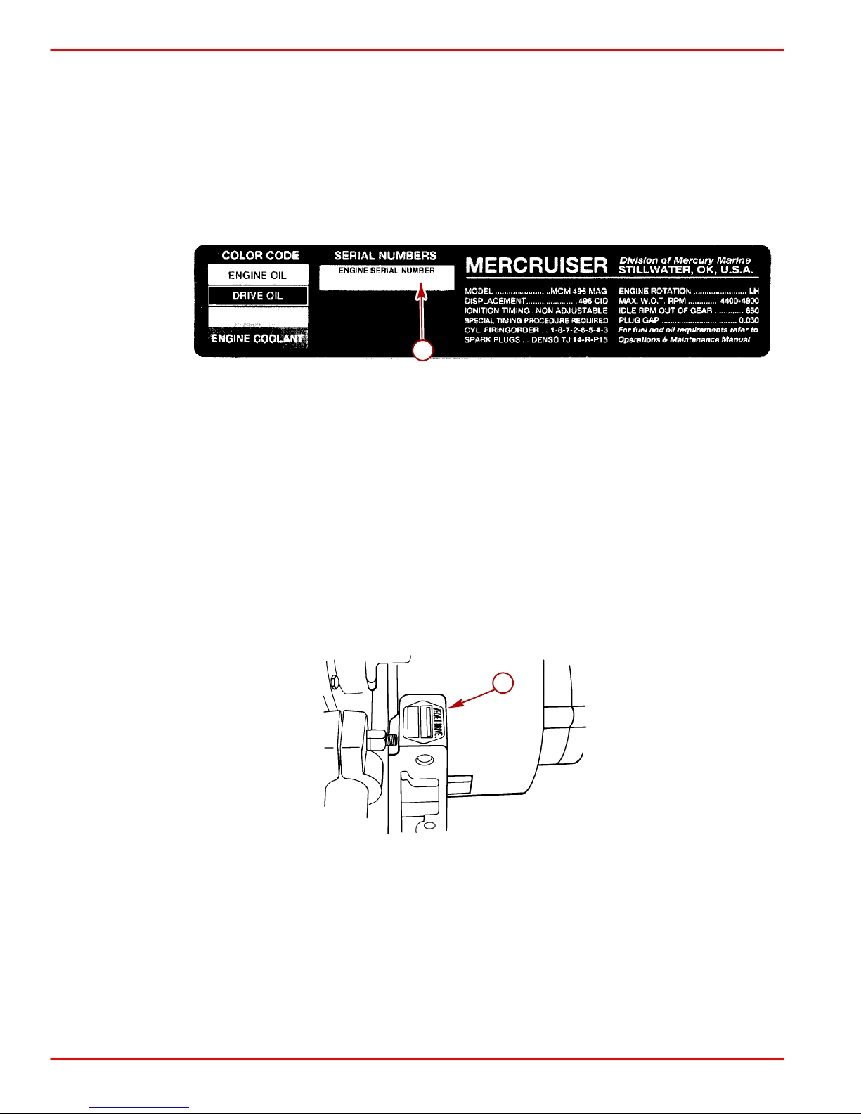
Serial Number Decal Placement
There are three engine serial number decal strips provided with each power package. One
should be used for each of the following:
• Engine Specification Decal
• Warranty Registration Card
• Operation and Maintenance Manual identification page.
Affix engine serial number decal to specification / serial number decal in position shown.
a-Specification/Serial Number Decal
Engine Rotation
Engine rotation is described when observed from the rear of the engine (transmission end)
looking forward (water pump end).
Engine rotation is indicated on engine specifications and serial number decal.
Transmissions
Velvet Drive Transmissions
On the Velvet Drive 5000A and 5000V Transmissions the transmission identification plate
indicates gear ratio, serial number and model.
a
77643
a
Velvet Drive 5000A - 8° Down-Angle T ransmission Shown (5000V V-Drive Similar)
a-Transmission Identification Plate
Page 4 of 58
71778
Page 5
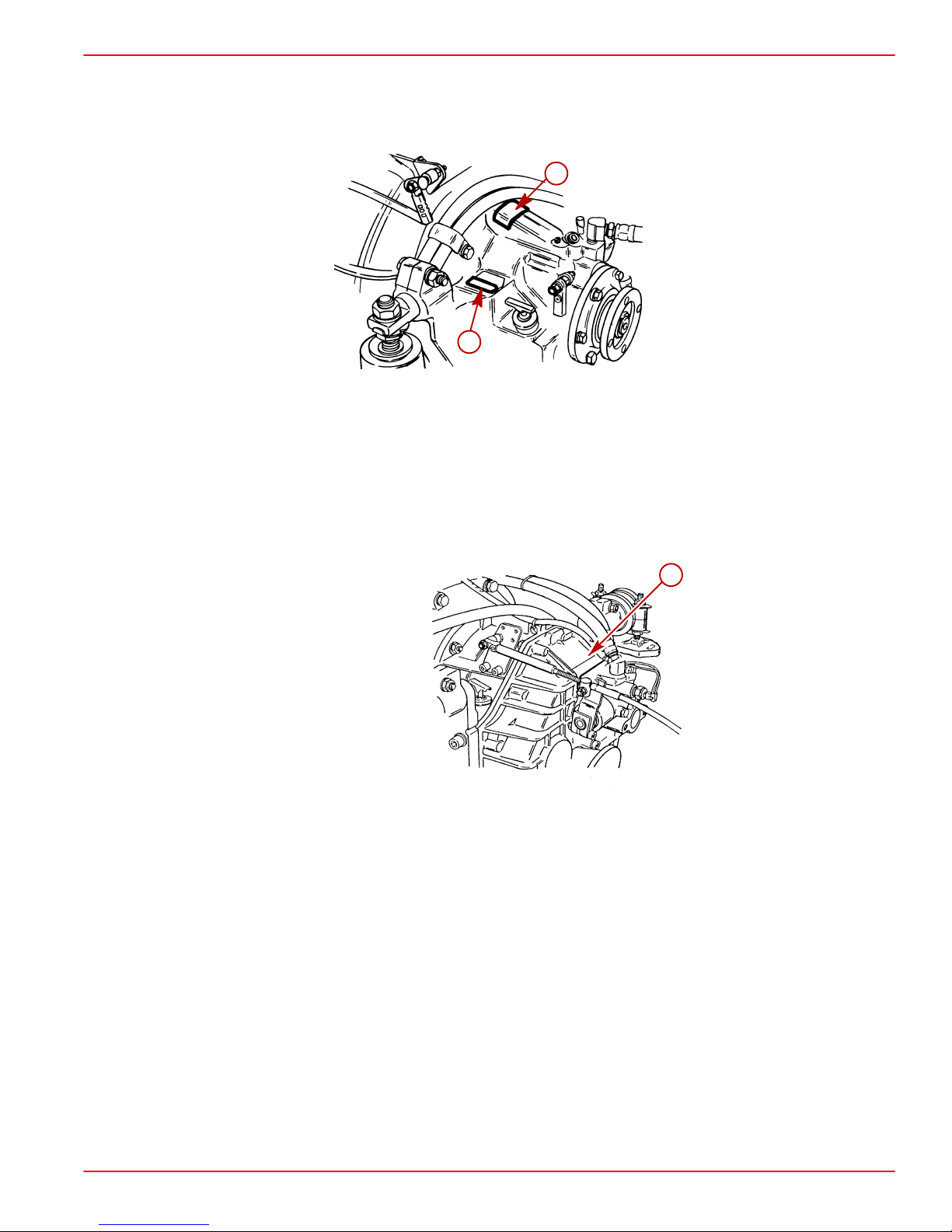
On Velvet Drive 72C Transmissions the gear ratio (in forward gear) is marked on
transmission identification plate. Transmission output shaft rotation and propeller rotation
required (in forward gear) is indicated on a decal on transmission case. Transmission
rotation is described when viewed from the rear of transmission.
Typical Transmission Shown
a-Transmission Identification Plate
b-Output Flange Rotation Decal
ZF / Hurth Transmissions
GASOLINE ENGINE 8.1 S INBOARD MODELS
b
a
22556
On the Hurth 8° Down-Angle and V-Drive Transmissions the transmission identification
plate indicates gear ratio, serial number and model.
a
73587
Typical Hurth Down-Angle Transmission Shown (V-Drive Identification Plate
Similarly Located)
a-Transmission Identification Plate
Page 5 of 58
Page 6
GASOLINE ENGINE 8.1 S INBOARD MODELS
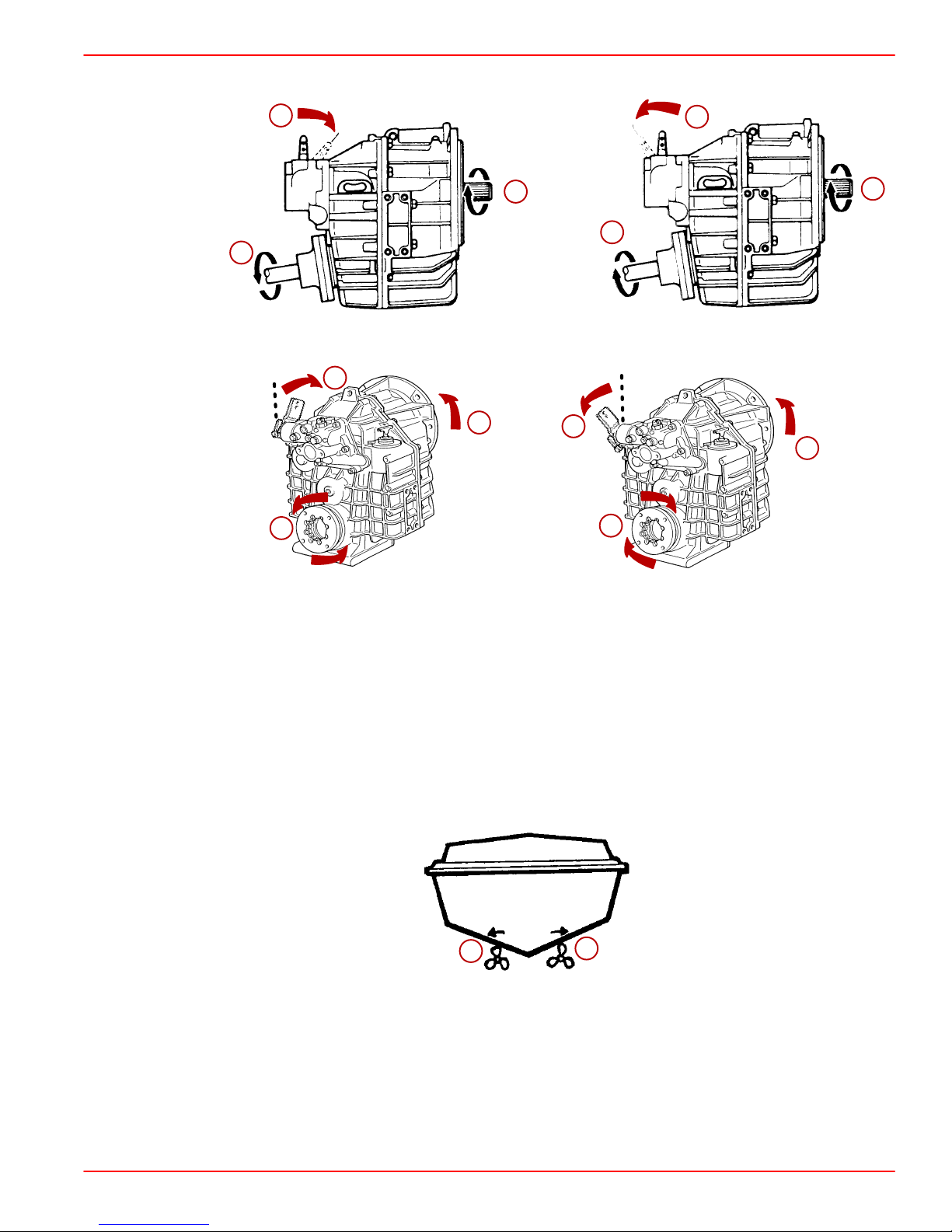
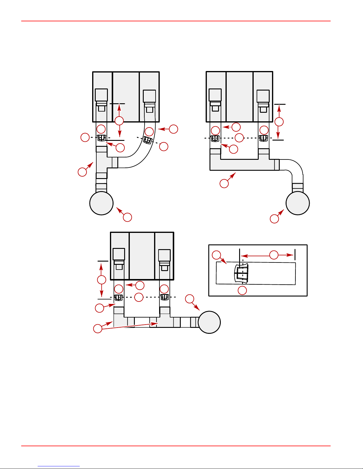
Propeller Rotation
Propeller rotation is not necessarily the same as engine rotation. Refer to the appropriate
following information and drawings for specific information.
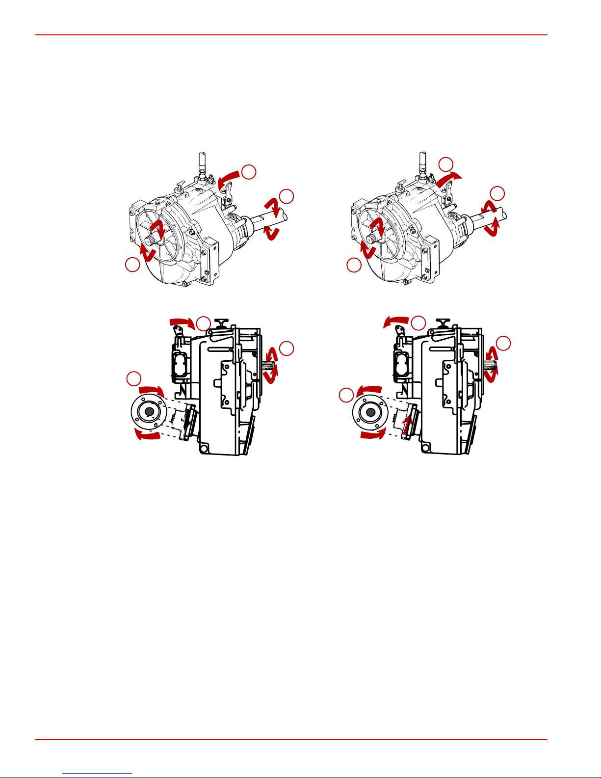
These transmissions are full power reversing transmissions, allowing a standard, LH
rotation engine to be used for both propeller rotations. Propeller rotation (output shaft
rotation) is determined by shift cable attachment at the remote control. Be sure to use
correct rotation propeller and shift cable hook up for direction desired.
a
c
b
Velvet Drive 5000A - 8° Down-Angle Transmission
b
a
b
f
g
d
e
71888
d
b
74604
Velvet Drive 5000V - V-Drive Transmissions
a-Direction Of Shift Lever Engagement (Toward Flywheel)
b-Engine/Transmission Input Shaft Rotation Direction (LH)
c-Transmission Output/Propeller Shaft Rotation Direction (LH)
d-Direction Of Shift Lever Engagement (Away From Flywheel)
e-Transmission Output/Propeller Shaft Rotation Direction (RH)
f-Transmission Output/Propeller Shaft Rotation Direction (LH As Viewed At
Propeller)
g-Transmission Output/Propeller Shaft Rotation Direction (RH As Viewed At The
Propeller)
Page 6 of 58
Page 7
Propeller Rotation (Continued)
GASOLINE ENGINE 8.1 S INBOARD MODELS
a
b
c
e
ZF / Hurth 630A or 800A - 8° Down-Angle Transmissions
a
b
c
72959
d
e
d
b
25506
b
72959
ZF / Hurth 630V - V-Drive Transmissions
a-Direction Of Shift Lever Engagement (Toward Flywheel)
b-Engine/Transmission Input Shaft Rotation Direction (LH)
c-Transmission Output/Propeller Shaft Rotation Direction (LH)
d-Direction Of Shift Lever Engagement (Away From Flywheel)
e-Transmission Output/Propeller Shaft Rotation Direction (RH)
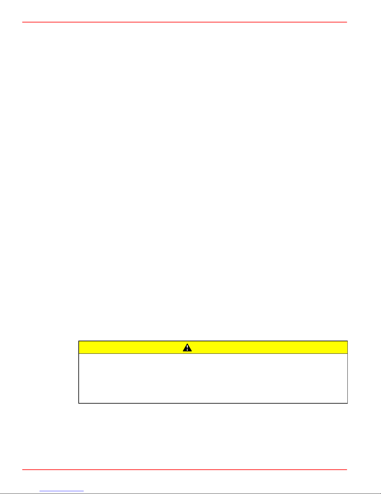
PROPELLER ROTATION ON DUAL INSTALLATIONS
Best all-around performance usually is obtained by installing engines so that propellers turn
outboard (looking at the stern).
b
Outboard Propeller Rotation
a-RH Rotation
b-LH Rotation
a
22457
Page 7 of 58
Page 8
GASOLINE ENGINE 8.1 S INBOARD MODELS
APPLICATION / RATIO SELECTION
The propeller shaft speed is determined by engine speed and the transmission ratio. Every
boat has a best shaft speed that directly relates to boat speed. If propeller shaft speeds are
too high an inordinately small propeller must be used resulting in poor performance. If they
are too low then too large a propeller must be used. Fast boats do best with direct drive or
small reductions. Heavier and slower boats require corresponding greater ratios of
reduction. 100 rpm of propeller shaft speed for each mph of boat speed is a rough rule of
thumb for selecting the drive ratio.
COUPLING
The coupling is a flange type coupler (available through Quicksilver Accessories). All
coupler bolts must be SAE Grade 8 (Metric Grade 10.9) or better, with a shoulder (grip
length) long enough to pass through the face mating plane of couplers. All coupler bolts
must be torqued to 50 lb-ft (68 Nm).
ENGINE/PROPELLER SHAFT INSTALLATION ANGLE
The transmission and engine should be mounted so that the angle relative to horizontal is
as shown in the installation drawings. Refer to individual installation drawings for each
specific engine and transmission.
IMPORTANT: Relative to horizontal, never install the engine with the front (pulley
end) down.
IMPORT ANT: On all engines, a high angle of installation [front (pulley end) of engine
up] along with low transmission oil levels can permit transmission pump cavitation
on some models when operating in rough water.
PROPELLER SHAFT DIAMETER
The required propeller shaft diameter can vary significantly depending on the material used,
strut and bearing design, engine horsepower and shaft rpm. Information is available from
the propeller shaft manufacturer and in marine handbooks for selecting the proper diameter.
Sufficient shaft diameter is critical for durability and to minimize vibration. As a guideline,
the propeller shaft should be a minimum of 1/14 the diameter of the propeller.
VELVET DRIVE 72C TRANSMISSIONS
Velvet Drive 72C In-Line Only – Use of proper rotation propeller (specified on transmission output flange rotation decal) is critical since the transmission must be operated in forward gear selector position only to drive boat forward. If the wrong rotation propeller is installed and transmission is operated in reverse to propel the boat
forward, transmission failure WILL occur. On engines which are equipped with Velvet Drive In-line transmissions, a LH propeller is required.
CAUTION
Page 8 of 58
Page 9
Installation Requirements
Engine Bed
Distance between starboard and port engine mount is 22-1/2 in. (572 mm). Engine bed must
position engine so that a minimum of 1/4 in. (6 mm) up and down adjustment still exists on
all 4 mounts after performing final engine alignment. This is necessary to allow for realigning
engine in the future.
NOTE: Although the engine mounts allow some adjustment, it is a good practice to ensure
that the front and rear mount locations in the vessel are in parallel planes. This may be
checked by tying a string from the left front mount location to the right rear mount location
and another from right front to left rear. The strings should touch where they cross
Engine Compartment
Boating standards (NMMA, ABYC) and Coast Guard regulations must be adhered
to when constructing the engine compartment.
Care must be exercised in the design and construction of the engine compartment. Seams
must be located so that any rain water that may leak through the seams, is directed away
from the air intake system.
GASOLINE ENGINE 8.1 S INBOARD MODELS
.
WARNING
VENTILATION
CAUTION
Water that runs onto the air intake may enter the engine and cause serious damage
to internal engine parts.
Engine compartments are being designed to be quieter. Insulation is the most common
material used to deaden the engine sound. Normally , the quieter the engine compartment,
the more insulation material used, resulting in less air space inside. The less air space inside
the engine compartment, the hotter the inside air temperature. Attention must be given to
the air temperature while the engine is running or for a period of time after the engine is shut
off (heat soak). Refer to the following information on Engine Compartment Ventilation.
According to Boating standards (NMMA, ABYC and others) and Coast Guard regulations
the engine compartment ventilation system has multiple tasks. Included are the following:
• To supply the engine with combustion air.
• To maintain a low temperature in the engine compartment.
Fresh air should enter the engine compartment as low as possible and the heated air should
be discharged from the highest point.
When sufficient ventilation is not provided, too much heat can build-up inside of engine
compartment and cause vapor locking. The engine will not want to restart after it has been
shut of f for a short period of time. If it does restart, the engine will quit when given the throttle
to get the boat up on plane or to pull up a water skier.
For engines utilizing fuels containing alcohol and the newer reformulated gasolines (Refer
to OEM Service Bulletin 95-2) proper ventilation is more critical to prevent vapor locking.
If a separate air shaft (or similar) is used to provide engine compartment ventilation or
additional ventilation, care must be taken to prevent seawater and spray from entering it.
Page 9 of 58
Page 10

GASOLINE ENGINE 8.1 S INBOARD MODELS
COMBUSTION AIR REQUIREMENTS
Engine compartments with natural draft ventilation must have vent openings of sufficient
size and location to accomplish the tasks previously outlined.
IMPORTANT: The size of ventilation openings must be increased if any auxiliary
equipment is located in the engine compartment.
The combustion air requirement (per engine) for the specified engines at WOT are given
in the chart below:
Combustion Air Requirements (Per Engine)
TEMPERATURE
Model
8.1S HO 726 ft3/min. (0.342 m3/sec) 6.0 ft
8.1S Horizon 657 ft3/min.(.3 m3/sec.) 6.0 ft
Engine Air Requirements at
WOT
Engine Physical Volume
3
(170 l)
3
(170 l)
The pressure differential between outside and inside the engine compartment must not
exceed the following value.
Maximum Pressure Differential at WOT
2 in. (51 mm) of water (measured with a manometer)
Air temperatures inside the engine compartments have been measured in excess of
200° F (82° C). The long term effect to fuel system components running at these
excessive temperatures is not known.
According to specification SAE J1223 for Marine Carburetors:
“The carburetor shall be capable of operation throughout an ambient (air temperature)
range from +20° to +176° F (–7° to +80° C) without failure.”
Carburetors, throttle body injection (TBI) units and components for multi-port EFI systems
used by Mercury MerCruiser meet this specification.
Under the hottest outside air temperature condition at which the boat will be operated, the
air temperature inside the engine compartment, measured at the flame arrestor, should not
exceed 176 ° F (80° C). Also, the temperature of the fuel being supplied to the engine should
not exceed 110° F (43° C) at any location between the fuel tank and the engine’s fuel pump.
Since many factors influence engine compartment temperature, temperature measurements should always be carried out. Test as follows:
Page 10 of 58
Page 11

TESTING
GASOLINE ENGINE 8.1 S INBOARD MODELS
NOTE: The boat being tested shall be a standard production boat fitted as it would be for
delivery to a dealer.
NOTE: Temperature test meter used shall be of the type that can be read without opening
the engine cover.
IMPORT ANT: During the test, in Step 1., engine compartments are to remain closed.
No outside air is to be forced into the engine compartment during the test and the
bilge blower should not be running.
1. Engine Running and Heat Soak Test:
a. Use 1 meter and 2-3 thermocouples. Place one thermocouple at the flame arrestor
to measure the inlet air temperature.
b. Place the second thermocouple at the fuel pump to measure the inlet fuel tempera-
ture.
c. A third thermocouple is needed if the fuel supply line between the tank and the fuel
pump is higher than the fuel pump. Place the third thermocouple at the highest point
of the supply line to measure the temperature of the fuel at that point.
2. Start engine and operate until engine is at normal operating temperature.
3. Operate engine at 1500 rpm (in NEUTRAL gear) for 15 minutes. Record temperature
readings at 5 minute intervals.
4. After 15 minutes at 1500 rpm, shut off engine and continue to record temperature
readings at 5 minute intervals for the next 45 minutes.
5. After the 45 minute heat soak test, start engine and idle (in NEUTRAL gear) for 20
minutes. Continue to record temperature readings at 5 minute intervals.
IMPORTANT: If the temperature at any location exceeds specifications, the engine
compartment will need additional ventilation until temperatures remain below these
specifications.
Page 11 of 58
Page 12
GASOLINE ENGINE 8.1 S INBOARD MODELS
Exhaust System
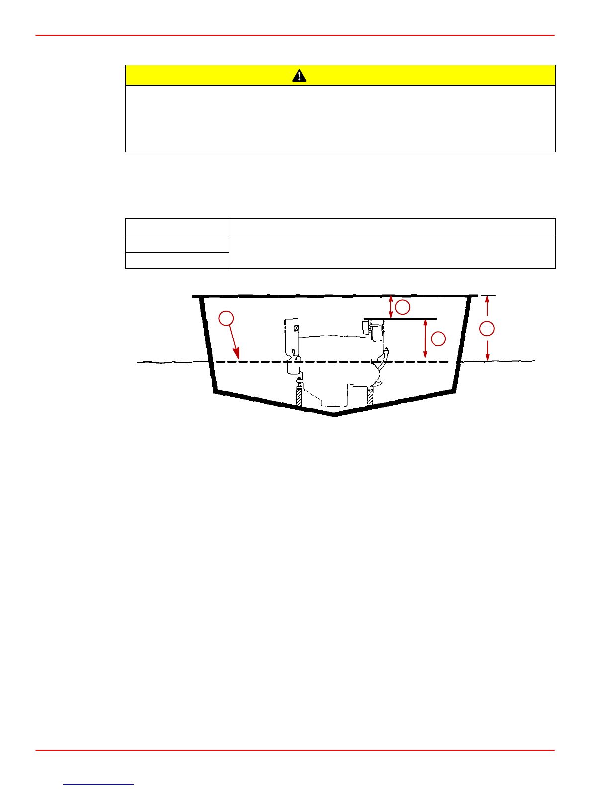
It is the responsibility of the boat manufacturer or installing dealer to properly locate the engine and install the exhaust system. Improper installation may allow water to enter the exhaust manifolds and combustion chambers and severely damage
the engine. Damage caused by water in the engine will not be covered by Mercury
MerCruiser Warranty, unless this damage is the result of defective parts.
Determine if exhaust elbow risers are required, by taking measurements “a” and “b,” with
boat at rest in the water and maximum load aboard. Subtract “b” from “a” to find “c.” If “c”
is less than specified in chart, select appropriate size exhaust elbow riser kit, and exhaust
extension kit if applicable, that will correctly position exhaust elbow.
CAUTION
Model
8.1S HO
8.1 Horizon
“c” Must Be 15 in. (381 mm) or More
“c” = “a” Minus “b”
b
d
a
c
77642
When designing and installing exhaust system, it is very important that the following points
be taken into consideration:
• System layout and construction must prevent cooling system discharge water from flowing back into engine and also must prevent seawater from entering engine via exhaust
system.
• The exhaust hoses and pipes must not be higher than exhaust elbows at any point.
• The drop must be constant so that a low spot does not exist at any point in the exhaust
hose or pipe.
Page 12 of 58
Page 13

GASOLINE ENGINE 8.1 S INBOARD MODELS
Continuous Downward Slope From Horizontal
Engine
Model
Installation
Minimum Maximum
Angle*
Down-Angle
Inboard
Down-Angle
Inboard
Down-Angle
Inboard
V-Drive
Inboard
V-Drive
Inboard
V-Drive
Inboard
* Fore - End of engine closest to bow of boat.
Fore End
Raised 2°
Fore End
Raised 4°
Fore End
Lowered 7°
Fore End
Lowered 2°
0° 9°
Fore End
Raised 3°
11°
13°
16°
2-5/16 in. (59 mm)
per 12 in. (305 mm)
2-3/4 in. (70 mm)
per 12 in. (305 mm)
3-7/16 in. (87 mm)
per 12 in. (305 mm)
7°
1-1/2 in. (38 mm)
per 12 in. (305 mm)
1-7/8 in. (48 mm)
per 12 in. (305 mm)
12°
2-1/2 in. (64 mm)
per 12 in. (305 mm)
21°
23°
26°
17°
19°
22°
4-5/8 in. (117 mm)
per 12 in. (305 mm)
5-1/16 in. (129 mm)
per 12 in. (305 mm)
5-7/8 in. (149 mm)
per 12 in. (305 mm)
3-11/16 in. (94 mm)
per 12 in. (305 mm)
4-1/8 in. (105 mm)
per 12 in. (305 mm)
4-7/8 in. (124 mm)
per 12 in. (305 mm)
• The first 18 in. (457 mm) of exhaust hose should drop the specified minimum relative to
horizontal. Thereafter, 3 ° of drop or 1/2 in. (13 mm) of drop per 12 in. (305 mm) relative to
horizontal is a MINIMUM requirement for the rest of the exhaust system.
• Exhaust hoses should not restrict the flow of discharge water from the elbow. The ex-
haust hose cannot be bent more than 5° relative to the exhaust elbow outlet as a hot spot
in the hose will occur and burn through.
• Exhaust outlet must be above the water line with boat at rest in the water and loaded
to capacity.
• System must not cause excessive back pressure when measured 10 in. (254 mm) aft
of the exhaust elbow outlets. Back pressure MUST NOT exceed 2 psi (14 kPa). Minimum exhaust hose sizes are given in the following chart:
Minimum Exhaust Outlet Hose Size
Model Single Outlet Dual Outlet
ALL 5 in. (127 mm) 4 in. (102 mm)
• Exhaust hoses must be secured at each connection with 2 hose clamps.
• An exhaust resonator is included with all 496 cid / 8.1L engines. Installation of this kit is
required on 496 MAG and 496 MAG HO sterndrive engines with a through the transom
or through the hull exhaust. MerCruiser strongly recommends the use of this kit on all
other models.
Page 13 of 58
Page 14
GASOLINE ENGINE 8.1 S INBOARD MODELS
• The exhaust resonator is positioned with the inside flat surface at the preferred distance
of 17 in. (432 mm) from the front edge of the exhaust hose but no closer than 2 in. (51
mm) to the exhaust outlet on sterndrives. The 17 in. (432 mm) dimension can be reduced, if necessary, to a MINIMUM of 13 in. (330 mm). This dimension must be the same
on both exhaust outlets.
c
a
a
b
a
e
d
e
b
e
d
c
a
g
g
f
b
f
c
c
a a
b
e
f
e
d
75768
g
a-Exhaust Resonator
b-Exhaust Hose
c-Dimension to Inside Flat Surface Of Resonator Approximately 17 in. (432 mm)
d-No Less Than 2 in. (51 mm) Between Collector And Resonator
e-Clamp - Positioned Around Center of Resonator
f-Exhaust Muffler
g-Collector
Page 14 of 58
Page 15
GASOLINE ENGINE 8.1 S INBOARD MODELS
NOTE: A kit is available, when applicable, to reduce from the 4 in. (102 mm) to 3 in. (76 mm).
Refer to the Quicksilver Accessories Guide, for kit part number.
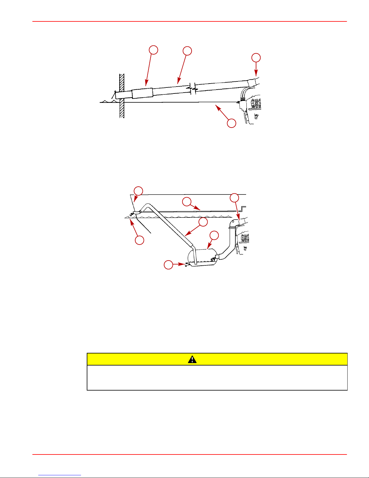
c
Typical Continuously Sloping Exhaust Line
a-Exhaust Elbow
b-Exhaust Hose Or Pipe
c-Muffler (If Equipped)
d-Waterline
b
b
a
d
a
d
71774
g
c
e
Typical Waterlift Muffler Exhaust System
a-Vent Line [1/4 in. (6 mm)]
b-Transom
c-Water Line
d-Exhaust Hose
e-Drain Valve
f-Water Lift Muffler
g-Exhaust Elbow
f
71775
CAUTION
Avoid severe engine damage. A 1/4 in. (6 mm) vent hose must be run from the highest point in the seawater system to the exhaust pipe after the water lift muffler to
break the vacuum and prevent water from back-filling the engine.
Page 15 of 58
Page 16

GASOLINE ENGINE 8.1 S INBOARD MODELS
Fuel Delivery System
Boating standards (NMMA, ABYC, etc.) and Coast Guard regulations must be
adhered to when installing fuel delivery system.
The main concern of a boat’s fuel system is safety; this must be achieved through a
technically sound installation and constant inspection.
The fuel system, from the filler pipe to the fuel pump is the same, in principle, for all boats.
The fuel tank is an integrated component of the boat. Refer to the special information on
service and maintenance, which you have received from the tank manufacturer.
Only a few points related to function and safety are listed here [Refer to boating standards
(NMMA, ABYC) and Coast Guard regulations for complete guidelines]:
• All connections should be on the upper side of the tank.
• The drain plug at the lowest point on the tank serves to permit the removal of water and
sediment.
• The tank breather pipe must have an inner diameter of at least 1/2 in. (13 mm) and must
be fitted with a swan neck to prevent water from entering the tank.
It is recommended that the exact route and length of the fuel lines be established at the first
installation of the engine to prevent problems later in connecting them to the engine.
WARNING
All fuel lines must be well secured. The holes where the lines run through the bulkheads
should be carefully rounded off, or protected with rubber grommets. This prevents damage
to the lines from abrasion.
The following, but not limited to the following, additional fuel connection related points, must
be considered [Refer to boating standards (NMMA, ABYC) and Coast Guard regulations for
complete guidelines]:
1. Fuel tank should be mounted below carburetor level (if possible) or gravity feed may
cause carburetor fuel inlet needle to unseat, and flooding may result.
2. The maximum measured vacuum at the engine’s fuel inlet must not exceed 2 in. Hg (6.9
kPa) at 650, 3000, full throttle rpm and back at idle rpm.
IMPORTANT: Vacuum reading higher than specified can cause vapor locking with
some of today’s fuels. It can also cause poor engine performance because of fuel
starvation.
3. Fuel pickup should be at least 1 in. (25 mm) from the bottom of fuel tank, to prevent
picking up impurities.
4. Fuel lines used must be Coast Guard approved (USCG Type A1).
Page 16 of 58
Page 17
Diameter of fittings and lines must not be smaller than 3/8 in. (10 mm) I.D. on 496 cid / 8.1L
engines.
5. On Multi-Engine Installations: It is best to use a fuel pickup and supply line for each
engine. If a single fuel pickup and supply line is used, fittings and line must not be smaller
than 1/2 in. (13 mm) I.D.
6. Larger diameter (than previously specified) lines and fittings must be used on
installations requiring long lines or numerous fittings.
7. Fuel lines should be installed free of stress and firmly secured to prevent vibration and/or
chafing.
8. Sharp bends in fuel lines should be avoided.
9. A flexible fuel line must be used to connect fuel supply line to fuel inlet fitting on engine,
to absorb deflection when engine is running.
SPECIAL INFORMATION ABOUT ELECTRIC FUEL PUMPS
CAUTION
The electric fuel pump and factory installed water separating fuel filter have been
carefully designed to function properly together . Do not install additional fuel filters
and/or water separating fuel filters between fuel tank and engine.
GASOLINE ENGINE 8.1 S INBOARD MODELS
The installation of additional filters may cause:
• Fuel Vapor Locking
• Difficult Warm-Starting
• Piston Detonation Due to Lean Fuel Mixture
• Poor Driveability
WARNING
Avoid gasoline fire or explosion. Improper installation of brass fittings or plugs into
fuel pump or fuel filter base can crack casting and/or cause a fuel leak.
IMPORTANT: The following information is provided to ensure proper installation of
brass fittings or plugs installed into fuel pump or fuel filter base:
• Use #592 Loctite Pipe Sealant with Teflon on threads of brass fittings or plugs. DO
NOT USE TEFLON TAPE.
• Brass fittings or plugs should first be threaded into fuel pump or fuel filter base
until finger tight.
• Fittings or plugs should then be tightened an additional 1-3/4 to 2-1/4 turns using
a wrench. DO NOT overtighten.
• T o prevent overtightening when installing a fuel line, the brass fittings should be
held with a suitable wrench as fuel line connectors are tightened securely.
Page 17 of 58
Page 18

GASOLINE ENGINE 8.1 S INBOARD MODELS
Battery
IMPORTANT: Boating industry standards (BIA, ABYC), federal standards and Coast
Guard regulations must be adhered to when installing a battery. Be sure the battery
cable installation meets the pull test requirements and that positive battery terminal
is properly insulated in accordance with regulations.
IMPORTANT: Engine electrical system is negative (–) ground. It is recommended
(required in some states) that battery be installed in an enclosed case. Refer to
regulations for your area.
Select a battery that meets all of the following specifications:
• 12-volt marine type.
• Tapered post connector or side terminal connectors. Do not use a battery with wing nut
connectors.
• Reserve battery capacity rating of at least:
Engine (cyl./type)
V8 MPI 496 (8.1) 650 cca/825 mca/150Ah
MULTIPLE EFI ENGINE BATTERY PRECAUTIONS
NOTE: All references to EFI models apply to EFI and MPI Engines. The following precautions apply to all EFI models.
NOTE: All references to ECM apply to all engine control modules
Situation
Alternators: Alternators are designed to charge the battery that supplies electrical power
to the engine that the alternator is mounted on. When batteries for two different engines are
connected, one alternator will supply all of the charging current for both batteries. Normally,
the other engine’s alternator will not be required to supply any charging current.
EFI Electronic Control Module (ECM): The ECM requires a stable voltage source. During
multiple engine operation, an onboard electrical device may cause a sudden drain of voltage
at the engine’s battery. The voltage may go below the ECM’s minimum required voltage.
Also, the alternator on the other engine may now start charging. This could cause a voltage
spike in the engine’s electrical system.
In either case, the ECM could shut off. When the voltage returns to the range that the ECM
requires, the ECM will reset itself. The engine will now run normally. This ECM shut down
usually happens so fast that the engine appears to have an ignition miss.
cid (l)
Minimum Required Cranking
Battery Size
Recommendations
Batteries: Boats with multi-engine EFI power packages require each engine be connected
to its own battery. This ensures that the engine’s Electronic Control Module (ECM) has a
stable voltage source.
Battery Switches: Battery switches should always be positioned so each engine is running
off its own battery . DO NOT operate engines with switches in BOTH or ALL position. In an
emergency, another engine’s battery can be used to start an engine with a dead battery.
Page 18 of 58
Page 19

Battery Isolators: Isolators can be used to charge an auxiliary battery used for powering
accessories in the boat. They should not be used to charge the battery of another engine
in the boat unless the type of isolator is specifically designed for this purpose.
NOTE: Sure Power Industries Inc. Model 32023A meets this design specification. Any other
manufacturer’s battery isolator that is the same type as the Sure Power, Inc. Model 32023A
could also be used.
1. The boat may have 2 engines connected to a single Model 32023A battery isolator.
2. The Model 32023A battery isolator is connected to 2 banks of batteries.
3. Each bank contains 2 batteries with the cranking battery for 1 engine in each bank.
4. The second battery in each bank is connected in parallel to the cranking battery.
5. The Model 32023A battery isolator is designed for this type of use; 2 battery banks, 2
6. When the engines are running, either engine’s alternator could be charging either bank
Generators: The generator’s battery should be considered another engine’s battery.
BATTERY CABLES
GASOLINE ENGINE 8.1 S INBOARD MODELS
charging sources, 120 amps (maximum alternator output).
of batteries through the Model 32023A battery isolator.
Select proper size positive (+) and negative (–) battery cables, using chart. Battery should
be located as close to engine as possible.
IMPORTANT: Terminals must be soldered to cable ends to ensure good electrical
contact. Use electrical grade (resin flux) solder only. Do not use acid flux solder as
it may cause corrosion and a subsequent failure.
Cable Length
Cable Gauge
Up to 3-1/2 ft (1.1 m) 4 (25 mm2)
3-1/2 - 6 ft (1.1-1.8 m) 2 (35 mm2)
6 - 7-1/2 ft (1.8-2.3 m) 1 (50 mm2)
7-1/2 - 9-1/2 ft (2.3-2.9 m) 0 (50 mm2)
9-1/2 - 12 ft (2.9-3.7 m) 00 (70 mm2)
12 - 15 ft (3.7-4.6 m) 000 (95 mm2)
15 - 19 ft (4.6-5.8 m) 0000 (120 mm2)
Page 19 of 58
Page 20

GASOLINE ENGINE 8.1 S INBOARD MODELS
EFI Electrical System Precautions
NOTE: All references to EFI models apply to EFI and MPI Engines. The following precautions apply to all EFI models.
Avoid damage to the EFI electrical system and components. Refer to the following
precautions when working on or around the EFI electrical harness or when adding
other electrical accessories:
• DO NOT tap accessories into engine harness.
• DO NOT puncture wires for testing (Probing).
• DO NOT reverse battery leads.
• DO NOT splice wires into harness.
• DO NOT attempt diagnostics without proper, approved Service Tools.
Instrumentation
If Quicksilver wiring harness is used, and a fused accessory panel is to be installed
(40-amp current draw maximum), be sure to connect it as shown in wiring diagram.
Do not connect accessory panel at any other location, as wires in wiring harness
may not be of sufficient size to handle current load.
CAUTION
CAUTION
We recommend the use of Quicksilver Instrumentation and Wiring harnesses. On dual
station applications, oil pressure and water temperature senders (on engine) must be
changed. Refer to Quicksilver Accessories Guide for selection.
The 4 basic gauges, which must be used with the engine, are:
• Tachometer
• Oil Pressure
• Water Temperature
• Voltmeter
Route instrumentation wiring harness back to engine, making sure that harness does not
rub or get pinched. If an extension harness is required, be sure to secure connection
properly. Fasten harnesses to boat at least every 18 in. (460 mm), using appropriate
fasteners.
Page 20 of 58
Page 21

Propeller Selection
IMPORTANT: Installed propeller must allow engine to run at its specified maximum
WOT rpm. Use an accurate service tachometer to verify engine operating rpm.
It is the responsibility of the boat manufacturer and/or the selling dealer to equip the power
package with the correct propeller. Refer to Quicksilver publication - Everything You Need
To Know About Propellers P/N 90-8614492. Specified engine WOT and operating rpm
range are listed in the Mercury MerCruiser Operation, Maintenance and Warranty Manual
attached to the engine.
Select a propeller that will allow the engine power package to operate at or near the top end
of the recommended WOT operating rpm range with a normal load.
If full throttle operation is below the recommended range, the propeller must be changed
to prevent loss of performance and possible engine damage. On the other hand, operating
an engine above the recommended operating rpm range will cause higher than normal wear
and/or damage.
After initial propeller selection, the following common problems may require that the
propeller be changed to a lower pitch.
• Warmer weather and greater humidity cause a loss of rpm.
• Operating in a higher elevation causes a loss of rpm.
GASOLINE ENGINE 8.1 S INBOARD MODELS
RPM REV-LIMITER
• Operating with increased load (additional passengers, pulling skiers) causes a loss of
rpm.
For better acceleration, such as is needed for water skiing, use the next lower pitch
propeller. Do not operate at full throttle when using the lower pitch propeller but not pulling
skiers.
Because of the many variables of boat design, only testing will determine the best propeller
for a particular application. Available propellers are listed in the Quicksilver Accessories
Guide.
See BOAT IN THE WATER TESTS, Maximum RPM Test at the back of this manual.
IMPORTANT: When selecting a propeller consider this additional information, if
applicable:
The engines listed in the following chart are equipped with an rpm rev-limiter that is
set to an upper (or limited) rpm amount. This limit is slightly above the normal
operating range of the engine and is designed to help prevent damage from
excessive engine rpm. Once the rpm drop into the recommended operating rpm
range normal engine operation resumes.
Engine Rev-Limiter
Model
8.1 S HO 4400 - 4800 4950
8.1 S Horizon 4200 - 4600 4750
Engine Recommended
Operating RPM Range
Rev-Limit RPM Setting
Page 21 of 58
Page 22

GASOLINE ENGINE 8.1 S INBOARD MODELS
Throttle/Shift Remote Control and Cables
Remote control and shift cable must position transmission shift lever exactly as
shown or transmission failure may occur. Do not remove poppet ball or spring.
Damage caused to transmission as a result of improper shift lever positioning will not be
covered by warranty.
To ensure proper shift and throttle operation, we recommend the use of a Quicksilver
remote control and cables. Refer to Quicksilver Accessories Guide for selection. If a
control other than Quicksilver is to be used, control must provide a shift cable travel of
2-3/4 in. (70 mm).
Seawater Connections
SEA WATER PICKUP AND HOSE
IMPORTANT: DO NOT install water pickup directly in line with propeller, as pickup
may create turbulence and allow air to flow into the propeller slipstream. This will
cause propeller ventilation and will adversely affect boat performance.
Water pickup must be large enough to permit suf ficient water flow to engine seawater pickup
pump for adequate engine cooling. Water pickup should be located as close to seawater
pickup pump inlet as possible and in an area where an uninterrupted, solid stream of water
will flow past when boat is underway.
CAUTION
Water inlet hose connections must be made with wire reinforced hose of adequate wall
thickness to prevent it from collapsing from pump suction. Be sure to secure hose
connections with hose clamps. Secure hose to prevent contact with any moving parts.
Seawater Pickup Hose Inner Diameter
SEACOCK
Seacock used must have an internal cross-sectional area equal to or greater than seawater
hose to prevent restricting water flow. A brass ball or gate valve is required.
Seacock Size Internal Cross-Sectional Area
Install the seacock in an area where it will be easily accessible and supported adequately
to prevent hose fatigue.
SEAWATER STRAINER
Strainer used must be of sufficient size to ensure that an adequate supply of water will be
maintained for cooling engine.
Seawater Strainer Minimum Flow Rate
The seawater strainer should be installed in an area where it will be easily accessible for
inspection and cleaning. The strainer should be installed in water inlet hose after the
seacock (water inlet valve) to allow operator to shut off water when cleaning strainer.
1-1/4 in. (32 mm)
1-1/4 in. (32 mm)
30 U.S. gal/min. (114 L/min.)
Page 22 of 58
Page 23

Hot Water Heater
IMPORTANT: When connecting a cabin heater or hot water heater, certain requirements must be met, including, but not limited to the following:
• Supply hose (from engine to heater) and return hose (from heater to engine)
• Make heater connections ONLY at locations indicated in the following informa-
• Refer to manufacturers’ instructions for complete installation information and
Avoid a performance loss and/or possible engine damage. Engine coolant must
flow continuously from the engine intake manifold to the engine water circulating
pump. NEVER close-off or block the coolant flow to or from a heater. All heater
installations must be plumbed in series with the supply and return connections.
Avoid engine overheating which could result in engine damage. An air pocket may
form in the closed cooling system if some coolant is lost from the system and the
cabin heater or hot water is mounted higher than the fill cap on the reservoir . Heater
must be mounted lower
GASOLINE ENGINE 8.1 S INBOARD MODELS
MUST NOT EXCEED 5/8 in. (16 mm) I.D. (inside diameter).
tion.
procedures.
CAUTION
CAUTION
than the fill cap of the reservoir.
IMPORTANT: Do not reposition engine temperature switch; it must remain where
installed by factory.
HOSE CONNECTION
b
a
77013
a-Supply Hose Connection
b-Return Hose Connection
Page 23 of 58
Page 24

GASOLINE ENGINE 8.1 S INBOARD MODELS
Engine Installation
Before Starting Installation read General Information and Installation Requirements completely.
Engine Oil Dipstick Location
Engine crankcase oil dipstick can be located on either starboard or port side of engine to
suit installation requirements. Place rubber cap over the dipstick tube that is not being used.
a
NOTICE to INSTALLER
a
b
a-Dipstick Tube
b-Dipstick
Battery Cable Connection
IMPORTANT: Engine electrical system is negative (–) ground.
IMPORTANT: Before connecting battery cables, make sure that grounding stud and
starter solenoid terminal are free of paint or any other material that could cause a
poor electrical connection.
1. Connect negative (BLK) battery cable to grounding stud on flywheel housing and tighten
nut securely.
2. Connect positive (RED) battery cable to 10 mm terminal on starter solenoid and tighten
nut securely.
a
77629
Page 24 of 58
Page 25

Engine Mount Pre-Adjustment
Engine compartment size may require the removal of additional components.
1. Remove engine cover.
2. Remove hardware holding engine to shipping pallet. Attach a suitable sling to lifting eyes
on engine. Lift engine from pallet with an overhead hoist.
GASOLINE ENGINE 8.1 S INBOARD MODELS
CAUTION
a
b
76938
77516
a-Rear Lifting Eye
b-Front Lifting Eye
3. Remove L-shaped shipping bracket from both rear (transmission) mounts. Retorque
mount bracket attaching bolt to 47 lb-ft (64 Nm).
a
b
Typical
a-L-shaped Bracket
b-Transmission Mount Bracket Attaching Bolt
IMPORTANT: Engine mounts must be adjusted, as explained in Steps 4. and 5., to
center mount adjustment and establish a uniform height on all mounts.
74623
4. Check all 4 engine mounts (2 front, 2 rear) to ensure that distance from bottom of mount
to bottom of trunnion is as shown. If not, loosen mount locking nut and turn adjusting nut
in direction required to obtain proper dimension, then retighten locking nut.
Page 25 of 58
Page 26

GASOLINE ENGINE 8.1 S INBOARD MODELS
5. Loosen clamping bolts and nuts on all 4 engine mount brackets to ensure the following:
• Large diameter of mount trunnion extended as shown.
• Each mount base is downward. Tighten clamping bolts and nuts slightly to prevent mov-
ing in or out. Mounts must be free to pivot when installing engine.
a
Typical Front Mount Typical Rear Mount
a-Locking Nut
b-Adjusting Nut
c-Trunnion Clamp Bolts And Nuts, With Lock Washers
d-3/8 in. + 1/16 in. (10 mm + 2 mm)
e-2-5/8 in. + 1/16 in. (67 mm + 2 mm)
f-Mount Trunnion
Initial Engine Alignment
d
c
d
f
a
f
c
e
b
e
70140
b
70158
NOTE: The center lifting eye tool (91-863375) used for engine alignment can be ordered
from the Quicksilver Accessories Guide.
a
77637
a-Center Lifting Eye Tool
Page 26 of 58
Page 27

GASOLINE ENGINE 8.1 S INBOARD MODELS
MODELS WITH 8° DOWN ANGLE TRANSMISSIONS - VELVET DRIVE OR ZF / HURTH
1. Lift engine into boat and position on engine bed so that transmission output flange and
propeller shaft coupler are visibly aligned (no visible gap seen between coupling faces
when butted together). Adjust engine bed height if necessary to obtain proper
alignment. DO NOT use mount adjustments to adjust engine position at this time.
c
b
a
72596
a-Propeller Shaft
b-Propeller Shaft Coupler
c-Transmission Output Flange
IMPORTANT: Engine bed must position engine so that a minimum of 1/4 in. (6 mm)
up and down adjustment still exists on all 4 mounts after performing initial alignment.
This is necessary to allow for final engine alignment.
c
b
a
a-Propeller Shaft
b-Propeller Shaft Coupler
c-Transmission Output Flange
74546
2. Ensure that all 4 mounts are positioned properly, then fasten mounts to engine bed with
3/8 in. (10 mm) diameter lag bolts (of sufficient length) and flat washers. Tighten lag bolts
securely.
3. Disconnect overhead hoist and remove sling.
Page 27 of 58
Page 28

GASOLINE ENGINE 8.1 S INBOARD MODELS
MODELS WITH V-DRIVE TRANSMISSIONS
1. Lift engine into boat and position so that enough propeller shaft protrudes through
transmission and output flange for propeller shaft coupler to be attached. Then install
coupler and position engine (no visible gap between coupling faces when butted
together). Adjust engine bed height if necessary to obtain proper alignment. DO NOT
use mount adjustments to adjust engine position at this time.
IMPORTANT: Engine bed must position engine so that a minimum of 1/4 in. (6 mm)
up and down adjustment still exists on all 4 mounts after performing final alignment.
This is necessary to allow for final engine alignment.
b
a
c
d
75534
Velvet Drive
d
c
a
50608 50608
ZF / Hurth 630V
a-Propeller Shaft
b-Propeller Shaft Coupler
c-Transmission Output Flange
d-No Visible Gap Allowed
2. Ensure that all 4 mounts are still positioned properly. Fasten mounts to engine bed with
3/8 in. (10 mm) diameter lag bolts (of sufficient length) and flat washers. Tighten lag bolts
securely.
b
3. Disconnect overhead hoist and remove sling.
Page 28 of 58
Page 29

Final Engine Alignment
To avoid vibration, noise and damage to transmission output shaft oil seal and
bearings, engine must be properly aligned.
IMPORTANT: Engine alignment MUST BE RECHECKED with boat in the water, fuel
tanks filled and with a normal load on board.
Engine must be aligned so that transmission output flange and propeller shaft coupling
centerlines are aligned and coupling faces are parallel within .003 in. (0.07 mm). This
applies to installations with solid couplings, as well as flexible couplings.
1. Check mating surfaces on transmission output flange and propeller shaft coupler to
make sure they are clean and flat.
2. Follow instructions a. or b.:
a. On V-Drive Transmission Models: Proceed to Step 3.
b. On Down Angle Transmission Models: Center propeller shaft in shaft log as
follows:
(1.)Push down and lift shaft as far as it will move. Then place shaft in the middle of
the movement.
GASOLINE ENGINE 8.1 S INBOARD MODELS
CAUTION
(2.)Move shaft to port and then to starboard as far as shaft will move. Then place
shaft in the middle of the movement.
(3.)With shaft in center of shaft log, as determined by above procedures (1.) and (2.),
align engine to shaft.
a
d
c
b
Typical Down Angle
a-Up
b-Down
c-Port
d-Starboard
72595
Page 29 of 58
Page 30

GASOLINE ENGINE 8.1 S INBOARD MODELS
3. Ensure that coupling centerlines align by butting propeller shaft coupler against
transmission output flange. Shoulder on propeller shaft coupler should engage recess
on transmission output flange face with no resistance.
Incorrect Correct
NOTE: Some propeller shaft couplers may not have a shoulder on mating face. On these
installations, use a straight edge to check centerline alignment.
72597
c
a
a-Transmission Output Flange
b-Propeller Shaft Coupler
c-Propeller Shaft
d-Straight Edge
b
d
74483
Page 30 of 58
Page 31

GASOLINE ENGINE 8.1 S INBOARD MODELS
4. Check for angular misalignment by hand holding coupling faces tightly together and
checking for a gap between coupling faces with a .003 in. (0.07 mm) feeler gauge at 90°
intervals.
a
b
c
Velvet Drive
b
c
a
ZF / Hurth
a-Propeller Shaft Coupler
b-Feeler Gauge
c-Transmission Output Flange
50609
75534
a
c
b
50608
Page 31 of 58
Page 32

GASOLINE ENGINE 8.1 S INBOARD MODELS
5. If coupling centerlines are not aligned or if coupling faces are more than .003 in.
(0.07 mm) out of parallel, adjust engine mounts.
a. TO ADJUST ENGINE UP OR DOWN: Loosen locking nut on mounts requiring
adjustment and turn adjusting nuts in desired direction to raise or lower.
IMPORTANT: Both front mounts (or rear mounts) adjusting nuts must be turned
equally to keep engine level from side to side.
a
c
b
d
70056
Typical Mount
a-Locking Nut
b-Adjusting Nut
c-Clamping Bolts And Nuts, With Lock Washers
d-Lag Bolt
NOTE: Some rear mounts have one (1) clamping bolt and nut on each side.
b. TO MOVE ENGINE TO THE LEFT OR RIGHT: Loosen clamping bolts and nuts on
all 4 mount brackets move engine to the left or right as necessary to obtain proper
alignment. A small amount of adjustment can be obtained with slot on front end of
some mounts. Loosen lag bolts (which fasten mounts to engine bed) and move
engine, as required. Retighten lag bolts securely.
IMPORTANT: Large diameter of mount trunnion MUST NOT extend over 1-3/4 in.
(45 mm) from mount brackets on any of the mounts.
6. After engine has been properly aligned, secure engine mounts.
7. Torque clamping bolts and nuts on all 4 mount brackets to 50 lb-ft (68 Nm).
8. Tighten locknut on all four mounts.
Page 32 of 58
Page 33

GASOLINE ENGINE 8.1 S INBOARD MODELS
9. Bend one of the tabs on the tab washer down onto the flat of the adjusting nut.
d
a
b
c
70057
a-Clamping Bolts And Nuts
b-Locknuts On All 4 Mounts
c-Tab On Tab Washer
d-Measurement - 1-3/4 in. (45 mm) Or Less
IMPORTANT: All coupler bolts must be SAE Grade 8 (Metric Grade 10.9) or better, with
a shoulder (grip length) sufficient to pass through the mating face plane of the
couplers.
10. Connect propeller shaft coupler to transmission output flange. Attach couplers together
with bolts, lockwashers and nuts. Torque to 50 lb-ft (68 Nm).
NOTE: If propeller shaft coupler has set screws, the shaft should be dimpled at set screw
locations. To drill dimples, remove propeller shaft coupler and drill shallow dimples at
locations marked with punch. Set screws should be safety wired after being tightened
securely.
b
c
d
e
a
50608
Velvet Drive V-Drive Shown (Others Similar)
a-Propeller Shaft Coupler
b-Bolts
c-Set Screws
d-Safety Wire
e-Transmission Output Flange
Page 33 of 58
Page 34

GASOLINE ENGINE 8.1 S INBOARD MODELS
Engine Connections
Seawater Pickup Pump Connection
1. Remove shipping cap and connect seawater inlet hose to the upper fitting.
a
a-Seawater Inlet Hose Attached To Upper Fitting
Fuel Supply Connection
77512
A flexible fuel line must be used to connect fuel line to engine to absorb deflection when
engine is running.
1. Remove shipping plug.
2. Connect fuel line to the fuel boost pump.
c
a
b
77629
a-Water Separating Fuel Filter
b-Fuel Boost Pump
c-Fuel Pump (Hidden)
Page 34 of 58
Page 35

Audio Warning System Connection
Alarm is not external ignition-proof, therefore, DO NOT mount alarm in engine or
fuel tank compartments.
1. Select a location for audio warning alarm which meets all of the following:
• alarm can be easily heard, yet is out of sight
• alarm can be easily accessed for installation and maintenance
• alarm will remain dry
• alarm is within length limits of the 18 in. PURPLE alarm wire that connects to the “I” termi-
nal or 12 volt source on switched side of ignition switch.
NOTE: The terminal to which wire is attached must have no voltage when ignition switch
is in the OFF position.
2. Place alarm in desired location. Secure alarm to wire bundle with sta-strap provided.
3. Connect PURPLE wire from alarm to any 12-volt source on switched side of ignition
switch. Tighten connection securely and coat with Quicksilver Liquid Neoprene.
4. Connect TAN/BLUE wire from the alarm to TAN/BLUE wire from instrument harness.
Ensure that bullet connector is tight.
GASOLINE ENGINE 8.1 S INBOARD MODELS
WARNING
5. Place small (transparent) decals on the bottom of the water temperature and the oil
pressure gauges.
6. Place the large decal on the instrument panel or other appropriate location easily viewed
by the operator.
ALARM INDICATES LOW
OIL OR OVERHEATING
a
APPLY THE PROPER DECAL TO THE DASHBOARD
OR OTHER APPROPRIATE LOCATION:
AUDIO WARNING HORN WILL SOUND WHEN:
1. ENGINE OIL PRESSURE IS TOO LOW,
2. ENGINE WATER TEMP. IS TOO HOT, OR
3. TRANSMISSION TEMPERATURE IS TOO HOT.
TO TEST THE AUDIO WARNING HORN:
TURN KEY TO ON POSITION (ENGINE OFF)
b
a-Small Decal (Transparent)
b-Large Decal
75434
Page 35 of 58
Page 36

GASOLINE ENGINE 8.1 S INBOARD MODELS
Electrical Connections
1. Connect the instrumentation wiring harness to engine harness plug at location shown.
a
a-Engine Harness Plug
76938
2. Coat both battery cable terminals with Quicksilver Liquid Neoprene. After liquid
neoprene has dried, slide rubber boot over positive cable connection.
d
b
74503
c
a-Negative (BLK) Battery Cable
b-Positive (RED) Battery Cable
c-Rubber Boot (Shipped with Engine)
d-90 Amp Fuse - DO NOT Remove
3. Drape battery cables over top of engine to prevent them from getting in the way during
installation.
a
74660
Page 36 of 58
Page 37

Exhaust System
Avoid exhaust hose failure. Discharge water from exhaust elbow must flow around
entire inside diameter of hose to avoid causing hot spots which could eventually
result in burned-through exhaust hoses. Exhaust hoses and/or tubes must be correctly connected to exhaust elbows so that they do not restrict the flow of discharge
water from exhaust elbow.
1. Exhaust hoses/tubes should be secured at each connection with at least 2 hose clamps.
2. Tighten all exhaust hose and/or exhaust tube clamps securely.
GASOLINE ENGINE 8.1 S INBOARD MODELS
CAUTION
b
b
a
b
a
b
a-Exhaust Tubes
b-Clamps
77593
Page 37 of 58
Page 38

GASOLINE ENGINE 8.1 S INBOARD MODELS
Shaft Log Seal Connection
Avoid engine overheating which could result in engine damage. Damaged caused
by improper cooling system connections for the propeller shaft log seal IS NOT
ered by the Mercury MerCruiser limited warranty.
IMPORTANT: Reducer fitting has been carefully sized to maintain the proper pressure
balance in the cooling system and must NOT be removed.
1. Remove plug from the reducer fitting on the starboard exhaust manifold (front end on
V-drives: rear end on conventional inboards).
IMPORTANT: If not using a shaft log seal, this fitting must remain plugged.
2. Attach the shaft log seal cooling water hose to the reducer fitting.
Engine damage may result from failure to route propeller shaft log seal hose properly. This could cause increased exhaust system corrosion, submersion damage or
freeze damage to engine.
The propeller shaft log seal hose should be routed so that a portion of the hose extends
above the top of the engine exhaust elbows. Hose must be securely fastened to keep it properly positioned.
CAUTION
cov-
CAUTION
a-Reducer Fitting
Page 38 of 58
a
77663
Page 39

GASOLINE ENGINE 8.1 S INBOARD MODELS
Shift Cable Installation And Adjustment
IMPORTANT: When installing shift cables, be sure that cables are routed in such a
way as to avoid contact with moving parts and/or sharp bends. All bends must make
greater than an 8 inch (203 mm) radius. DO NOT fasten any items to shift cables.
Shift cable must be hooked up to remote control before starting installation and adjustment
procedures. Refer to Transmission - Propeller Rotation, for transmission shift lever direction
of movement versus propeller shaft output direction of rotation.
Velvet Drive Transmissions - 5000 Series (8° Down Angle and V-Drive)
For Left-Hand Propeller Shaft Rotation: Shift cable hookup at remote control must result
in shift cable end guide moving in direction “A” when remote control handle is placed in
forward position.
For Right-Hand Propeller Shaft Rotation: Shift cable hookup at remote control must
result in shift cable end guide moving in direction “B” when remote control handle is placed
in forward position.
A
B
23242
Remote control must provide a total shift cable travel (at transmission end) of at least
2-3/4 in. (70 mm). This is necessary to position transmission shift lever fully in the forward
and reverse gear positions. Insufficient shift cable travel can result in transmission failure.
a
72602
a-2-3/4 In. (70 mm) Minimum
WARNING
Avoid serious injury or property damage caused by improper shifting. Anchor stud
for shift cable must be installed in the correct hole.
Page 39 of 58
Page 40

GASOLINE ENGINE 8.1 S INBOARD MODELS
CONNECT AND ADJUST QUICKSILVER SHIFT CABLES
1. Be certain anchor stud is installed in the front hole.
b a
a-Shift Cable Bracket
b-Anchor Stud In Front Hole
2. Place remote control shift lever and transmission shift lever in NEUTRAL position.
3. Remove nuts and washers from shift cable attaching studs.
73284
4. Locate center of remote control and control shift cable play (backlash) as follows:
a. Ensure that remote control is in NEUTRAL position.
b. Push in on control cable end with enough pressure to remove play; mark position
“a” on tube.
c. Pull out on control cable end with enough effort to remove play; mark position “b”
on tube.
d. Measure distance between marks “a” and “b;” mark position “c,” half-way between
marks “a” and “b.”
b
c
c
a
72603
5. Center cable-end play, then adjust cable barrel to align holes in barrel and in cable end
guide with attaching points on transmission.
6. Temporarily install shift cable. Do not secure at this time.
7. Place remote control shift lever in gear and check position of transmission shift lever.
Shift lever must be positioned in the desired detent hole.
Page 40 of 58
Page 41

GASOLINE ENGINE 8.1 S INBOARD MODELS
CAUTION
Transmission failure may occur. Velvet Drive Transmission Warranty is jeopardized
if the shift lever poppet ball or spring is permanently removed, if the shift lever is
repositioned or changed in any manner or if remote control and shift cable do not
position shift lever exactly as shown.
a
e
b
c
d
73248
Velvet Drive 5000 Series (8°Down Angle Shown, V-Drive Similar)
a-Transmission Shift Lever
b-Poppet Ball Must Be Centered In This Detent Hole When Left-Hand Propeller
Shaft Rotation Is Desired
c-Poppet Ball Must Be Centered In This Detent Hole When Right-Hand Propeller
Shaft Rotation Is Desired
d-Poppet Ball Must Be Centered In This Detent Hole For Neutral Position
e-Install Shift Lever Stud In This Hole when Using Quicksilver Shift Cables
8. Place remote control shift lever in opposite gear position and again check transmission
shift lever position. Lever must be positioned in the desired detent hole.
9. If transmission shift lever will position properly in one gear, but not in the other, recheck
shift cable adjustment.
10. If transmission shift lever will not position properly in both gears, move transmission shift
lever stud to the other hole and recheck shift cable position.
11. If transmission shift lever is still not positioned properly for both gears, move anchor stud
on shift cable bracket to another hole and recheck shift cable position.
Page 41 of 58
Page 42

GASOLINE ENGINE 8.1 S INBOARD MODELS
12. If proper positioning is still not obtained, remote control does not provide sufficient shift
cable travel and must be replaced.
b
Typical ZF / Hurth Transmission Shown
a-Shift Lever
b-Shift Cable Bracket
a
73587
13. Install nut and washer to cable end guide stud. Tighten until they contact, then loosen
1/2 turn.
14. Install nut and washer to cable barrel stud. Tighten securely, but DO NOT overtighten.
e
b
a
c
g
d
b
c
f
71780
71972
e
Typical Single Cable Installation - Rear Approach
a-Cable End Guide
b-Spacer (As Required)
c-Elastic Stop Nut And Washer
d-Bushings
e-Cable Barrel Location
f-Cable Barrel Stud
g-Cable End Guide Stud
Page 42 of 58
Page 43

GASOLINE ENGINE 8.1 S INBOARD MODELS
e
a
c
71897
Typical Dual Cable Installation - Rear Approach
a-Cable End Guide
b-Spacer (As Required)
c-Elastic Stop Nut And Washer
d-Bushings
e-Cable Barrel Location
f-Cable Barrel Stud
g-Cable End Guide Stud
g
b
d
f
50073
e
Velvet Drive Transmissions - 72C In-Line
IMPORT ANT: V elvet Drive Transmission Warranty is jeopardized if the shift lever poppet ball or spring is permanently removed, if the shift lever is repositioned or changed
in any manner or if remote control and cable do not position shift lever correctly.
FNR––
a
e
b
a-Transmission Shift Lever
b-Shift Lever MUST BE Over This Letter In FORWARD
c-Shift Lever MUST BE Over This Letter In REVERSE
d-Poppet Ball MUST BE Centered in Detent Hole for Each F-N-R Position (For-
ward Gear Shown)
e-Install Shift Lever Stud in This Hole, If Necessary, To Center Poppet Ball in For-
ward and Reverse Detent Holes
F
R
d
c
22457
Page 43 of 58
Page 44

GASOLINE ENGINE 8.1 S INBOARD MODELS
1. Verify shift cable stud is in appropriate stud hole as indicated. Tighten elastic stop nut
securely.
a-8.1L Shift Cable Anchor Stud Hole
2. Place remote control shift lever and transmission shift lever in neutral position.
3. Remove nuts and washers from shift cable attaching studs.
4. Locate center of remote control and control shift cable play (backlash), as follows:
a. Ensure that remote control is in neutral position.
a
50947
b. Push in on control cable end with enough pressure to remove play and mark position
“a” on tube.
c. Pull out on control cable end with enough pressure to remove play and mark position
“b” on tube.
d. Measure distance between marks “a” and “b,” and mark position “c,” half-way
between marks “a” and “b.”
b
c
a
c
22024
5. Center cable-end play, then adjust cable barrel to align holes in barrel and in cable end
guide, with attaching points on transmission.
6. Temporarily install shift cable. Do not secure at this time.
7. Place remote control shift lever in forward gear position and check position of transmission shift lever. Shift lever must be positioned as previously indicated.
8. Place remote control lever in reverse gear position and again check shift lever position.
Lever must be positioned as previously indicated.
9. If transmission shift lever will position properly in one gear, but not in the other, recheck
shift cable adjustment.
10. If transmission shift lever will not position properly in both gears, move transmission shift
lever stud to the other hole and recheck shift cable position.
Page 44 of 58
Page 45

GASOLINE ENGINE 8.1 S INBOARD MODELS
11. If transmission shift lever is still not positioned properly for both gears, move anchor stud
on shift cable bracket to another hole and recheck shift cable position.
12. If proper positioning is still not obtained, remote control does not provide sufficient shift
cable travel and must be replaced.
13. Reattach nut and washer to cable end guide stud. Tighten until they contact, then loosen
1/2 turn.
14. Reattach nut and washer to cable barrel stud. Tighten securely, but DO NOT
overtighten.
g
a
b
f
e
c
Rear Entry Single Station Installation In-Line And V-Drive
d
e
g
b
f
a
50947
c
d
Rear Entry Dual Station Installation In-Line And V-Drive
a-Cable End Guide
b-Cable Barrel
c-Cable Barrel Stud
d-Elastic Stop Nut And Washer
e-Spacer
f-Cable End Guide Stud
g-Elastic Stop Nut And Washer
50947
Page 45 of 58
Page 46

GASOLINE ENGINE 8.1 S INBOARD MODELS
b
d
a
c
g
f
e
Front Entry Single Station Installation In-Line And V-Drive
d
b
a
c
g
e
f
Front Entry Dual Station Installation In-Line And V-Drive
a-Cable End Guide
b-Cable Barrel
c-Cable Barrel Stud
d-Elastic Stop Nut And Washer
e-Spacer
f-Cable End Guide Stud
g-Elastic Stop Nut And Washer
50946
50946
Page 46 of 58
NOTE: For models equipped with a dual station shift bracket such as the one shown, refer
to shift cable manufacturer’s instructions for adjusting the cable. Shift lever must be positioned as stated in the preceding steps.
22457
Dual Station Shift Bracket (Not Quicksilver)
Page 47

ZF / Hurth Transmissions - HSW 630A, 630V, 800A
IMPORTANT: These Hurth transmissions are full reversing transmissions. Direction
of output/propeller rotation is determined by hookup of shift cable at remote control.
Shift cable must be hooked up to remote control before starting installation and adjustment
procedures. Refer to Transmission - Propeller Rotation, for transmission shift lever direction
of movement versus propeller shaft output direction of rotation.
For Right Hand Propeller Rotation – Shift cable hookup at remote control must result in
shift cable end guide moving in direction “A” when remote control handle is placed in
forward position.
For Left Hand Propeller Rotation – Shift cable hookup at remote control must result in shift
cable end guide moving in direction “B” when remote control handle is placed in forward
position.
A
B
GASOLINE ENGINE 8.1 S INBOARD MODELS
23242
WARNING
Avoid serious injury or property damage caused by improper shifting. Anchor stud
for shift cable must be installed in the correct hole.
1. Be certain anchor stud is installed in the correct mount hole as shown by the following
illustration.
a
71020
Shift Cable Bracket - Anchor Stud Positions
a-Cable Bracket
b-Quicksilver Shift Cable Anchor Stud Location - 630A and 630V
c-Quicksilver Shift Cable Anchor Stud Location - 800A
b
c
a
73588
IMPORTANT: When installing shift cables, be sure that cables are routed in such a
way as to avoid contact with moving parts and/or sharp bends. All bends must make
greater than an 8 inch (203 mm) radius. DO NOT fasten any items to shift cables.
2. Place remote control shift lever, and transmission shift lever, in NEUTRAL position.
3. Remove nuts and washers from shift cable attaching studs.
4. Locate center of remote control and control shift cable play (backlash), as follows:
Page 47 of 58
Page 48

GASOLINE ENGINE 8.1 S INBOARD MODELS
a. Check that remote control is in neutral position.
b. Push in on control cable end with enough pressure to remove play, and mark
position “a” on tube.
c. Pull out on control cable end with enough pressure to remove play, and mark
position “b” on tube.
d. Measure distance between marks “a” and “b,” and mark position “c,” half-way
between marks “a” and “b.”
b
c
a
c
22024
5. Center cable-end play; then, adjust cable barrel to align holes in barrel and in cable end
guide with attaching points on transmission.
6. Temporarily install shift cable. Do not secure at this time.
a
Page 48 of 58
73587
Typical
a-Shift Cable End Guide
IMPORT ANT: Transmission is fully in gear when shift lever comes to a stop in either
direction.
7. Place remote control shift lever in forward gear position. Ensure that transmission is fully
in gear, as follows:
a. Hold shift lever in position.
b. Carefully slide shift cable off of anchor points.
c. Attempt to move shift lever further.
8. Place remote control shift lever in the reverse gear position. Ensure that transmission
is fully in gear, following same procedure.
9. If transmission shift lever will position properly in one gear, but not in the other, recheck
shift cable adjustment.
Page 49

GASOLINE ENGINE 8.1 S INBOARD MODELS
10. If transmission shift lever will not position properly in both gears, move transmission shift
lever stud to the other hole and recheck shift cable position.
11. If transmission shift lever is still not positioned properly for both gears, move anchor stud
on shift cable bracket to another hole and recheck shift cable position.
12. If proper positioning is still not obtained, remote control does not provide sufficient shift
cable travel and must be replaced.
b
a
73587
Typical ZF / Hurth Transmission Shown
a-Shift Lever
b-Shift Cable Bracket
13. Reattach locknut and washer to cable end guide stud. Tighten until they contact, then
loosen 1/2 turn.
14. Reattach locknut and washer to cable barrel stud. Tighten securely, but DO NOT
overtighten.
NOTE: To change cable approach direction on single or dual station installations, only the
spacers/bushings have to be switched to the opposite stud (the studs are identical).
Page 49 of 58
Page 50

GASOLINE ENGINE 8.1 S INBOARD MODELS
e
73589
Typical Single Cable - Forward Entry
a-Cable End Guide
b-Locknut and Washer
c-Spacer (Fits Over Bushings)
d-Bushings
e-Cable Barrel Location
f-Spacer (Fits Over Stud)
g-Cable Barrel Stud
h-Cable End Guide Stud
e
d
c
g
b
e
h
a
f
b
71210
a
f
h
b
73587
Typical Single Cable - Rear Entry
a-Cable End Guide
b-Locknut And Washer
c-Spacer (Fits Over Bushings)
d-Bushings
e-Cable Barrel Location
f-Spacer (Fits Over Stud)
g-Cable Barrel Stud
h-Cable End Guide Stud
d
g
e
c
50229
b
Page 50 of 58
Page 51

GASOLINE ENGINE 8.1 S INBOARD MODELS
e
73590
Typical Dual Cable - Forward Entry
a-Cable End Guides
b-Locknut And Washer
c-Spacer (Fits Over Stud)
d-Bushings
e-Cable Barrel Locations
f-Cable Barrel Stud
g-Cable End Guide Stud
e
f
b
d
c
g
a
b
71211
e
Typical Dual Cable - Rear Entry
a-Cable End Guides
b-Locknut And Washer
c-Spacer (Fits Over Stud)
d-Bushings
e-Cable Barrel Locations
f-Cable Barrel Stud
g-Cable End Guide Stud
73591
c
g
b
a
d
f
e
b
50073
Page 51 of 58
Page 52

GASOLINE ENGINE 8.1 S INBOARD MODELS
Predelivery Preparation
Before starting Predelivery read General Information and Installation Requirements completely.
Battery Connection
IMPORTANT: Engine electrical system is negative (–) ground.
1. Connect engine POSITIVE (+) battery cable (usually RED) to POSITIVE (+) battery
terminal.
2. Connect engine NEGATIVE (–) battery cable (usually BLACK) to NEGATIVE (–) battery
terminal.
3. Make sure that all battery terminal connections are tight and then coat connections and
terminals with a battery terminal anti-corrosion spray to help retard corrosion.
Test Running Engine
NOTICE
If engine is to be tested on land, propeller must be removed.
If engine is to be tested on land, water must be supplied to seawater pickup pump.
DO NOT run engine above 1500 rpm.
Boat In The Water Tests
IMPORTANT: Engine alignment MUST BE CHECKED with boat in the water, fuel tanks
filled and a normal load on board.
WIDE OPEN THROTTLE TEST
IMPORT ANT: T o operate engine at full throttle before the break-in period is complete,
follow this procedure.
1. Start engine and operate at idle rpm until normal operating temperature is reached.
2. Run boat up on plane.
3. Advance engine rpm (in 200 rpm increments) until engine reaches its maximum rated
rpm.
WARNING
CAUTION
To test if the correct propeller has been installed, operate boat (with normal load on board)
at WOT and check rpm with an accurate tachometer. Engine rpm should be near top of the
specified range so that, under a heavy load, engine speed will not fall below specifications.
If engine speed is too high, replace propeller with a higher pitch propeller.
Page 52 of 58
Page 53

Cold Weather and Extended Storage Draining
NOTE: If recommended coolant is unavailable, any type of ethylene glycol based antifreeze
may be used, but it will require replacement every two years.
IMPORTANT: Drain seawater section of closed cooling system only.
IMPORTANT: Boat must be as level as possible to ensure complete draining of
cooling system.
CAUTION
Seawater section of cooling system MUST BE COMPLETELY drained for winter
storage or immediately after cold weather use if the possibility of freezing
temperatures exist. Failure to comply may result in trapped water causing freeze
and/or corrosion damage to engine. Damage caused by freezing IS NOT
the Mercury MerCruiser Limited Warranty.
CAUTION
If engine will be exposed to freezing temperatures, ensure closed cooling section
is filled with an ethylene glycol antifreeze and water solution properly mixed to protect engine to lowest temperature to which it will be exposed.
IMPORTANT: Closed cooling section must be kept filled year-round with
recommended coolant.
GASOLINE ENGINE 8.1 S INBOARD MODELS
covered by
IMPORTANT: Do not use Propylene Glycol Antifreeze in the closed cooling section
of the engine.
Ensure that boat is out of the water or seacock is closed and that bilge pump is operating. Excess water in the bilge can damage engine or cause boat to sink.
SINGLE POINT DRAIN SYSTEM
Freeze damage can occur if operating where temperatures are below 32° F. Use
Manual Drain System to ensure heat exchanger is completely drained.
NOTE: This procedure is written for the air pump that is attached to the engine. However,
any air source can be used.
1. Remove air pump from engine.
2. Ensure that lever on top of pump is flush with the handle (horizontal).
CAUTION
CAUTION
Page 53 of 58
Page 54

GASOLINE ENGINE 8.1 S INBOARD MODELS
3. Install air pump on the actuator fitting.
c
e
a
d
77638
b
c
a
b
77516
a-Actuator Fitting
b-Green Indicators
c-Manual Release Valve
d-Air Pump
e-Lever
4. Pull lever on air pump up (vertical) to lock pump on actuator fitting.
5. Pump air into the system until both green indicators extend and water drains from both
sides of the engine.
6. Most water will drain from the engine in 3-4 minutes, however , some will remain trapped
in the heat exchanger. In order to prevent freeze damage, leave system pressurized
while transporting boat or during other maintenance items to allow the remaining water
to drain.
IMPORTANT: Before launching boat, pull up on manual release valve. Verify that
green indicators are no longer extended.
CAUTION
Manual release valve may not close completely. Ensure valve is completely seated.
Page 54 of 58
Page 55

MANUAL DRAIN SYSTEM
NOTE: If air actuated drain system fails, use the blue drain plugs to drain engine.
NOTE: It may be necessary to lift, bend or lower hoses to allow water to drain completely
when hoses are disconnected.
1. Remove drain plugs from front and rear of cool fuel cell and from the seawater pump.
2. Remove end caps, sealing washers and gaskets from heat exchangers.
a-Heat Exchanger
b-Gaskets
c-Sealing Washer
d-End Cap
GASOLINE ENGINE 8.1 S INBOARD MODELS
a
b
c
d
71515
3. Clean out drain holes using a stiff wire. Do this until entire system is drained.
4. Remove both hoses from seawater pump.
a
b
77512
a-Seawater Inlet Hose
b-Hose To Cooler
5. Crank engine over slightly with starter motor to purge any water trapped in seawater
pickup pump. DO NOT ALLOW ENGINE TO START.
Page 55 of 58
Page 56

GASOLINE ENGINE 8.1 S INBOARD MODELS
Coolant And Water Flow Diagrams
NOTE: Certain components in the following diagram may look different than on your
particular power package, but the water and coolant flow paths remain similar on all
engines.
14
12
c
13
a
b
4
3
5
6
Page 56 of 58
14
13
12
d
2
1
c
7
11
8
9
10
Page 57

1 - Seapump
2 - Air Actuator
3 - Transmission Cooler
4 - Oil Cooler
5 - Fuel Cooler
6 - Air Actuator
7 - Heat Exchanger
8 - Thermostat
9 - Crossover
10 - Water Circulating Pump
11 - Coolant Reservoir
12 - Exhaust Manifold
13 - Elbow
14 - Water And Exhaust Outlet
a-Seawater
b-Coolant
c-To Air Actuator
d-Seawater Inlet
GASOLINE ENGINE 8.1 S INBOARD MODELS
Page 57 of 58
Page 58

GASOLINE ENGINE 8.1 S INBOARD MODELS
Predelivery Inspection
Not Check/
Applicable Adjust
CHECK BEFORE RUNNING ON THE WATER TEST
Drain plug in and petcocks Engine alignment (Inboards only)
closed
Seawater inlet valve open Starter neutral safety
Engine mounts tight
Engine alignment
Drive unit fasteners torqued
Power trim cylinders fasteners
tight Oil leaks
Battery fully charged and secured
All electrical connections tight
Exhaust system hose clamps
tight Ignition timing
All fuel connections tight
Correct rotation propeller
(installed and torqued)
Throttle, shift and steering system Forward - Neutral - Reverse
fasteners tightened properly gear operation
Throttle plates open and close Steering operation throughout
completely range
Crankcase oil level Acceleration from idle rpm
Not Check/
Applicable Adjust
switch operation
Water pump operation
Instruments(s) operation
Fuel leaks
Water leaks
Exhaust leaks
Idle RPM, within specifications
Power trim oil level WOT RPM within
specifications (in forward gear)
Sterndrive unit oil level
Power trim operation
Power steering fluid level
Trim tab adjustment
Closed cooling level
Boat handling
Transmission fluid level
AFTER ON WATER TEST
Alternator belt tension
Propeller nut torque
Seawater pickup pump belt
tension
Fuel, oil, coolant, water and fluid
Power steering pump belt tension leaks
Audio warning system operation Oil and fluid levels
Apply Quicksilver Corrosion Guard to
engine package
Page 58 of 58
 Loading...