

Page 1

8M0147199 618 eng
MercMonitor
© 2018 Mercury Marine
Page 2

eng
Page 3

General Information
Basic Operation and Features............................................................................ 1
MercMonitor Gateway Models Description......................................................... 3
MercMonitor Gateway Protocol Acceptance Description.................................... 7
Connection to a Non‑SmartCraft Network........................................................ 10
Automatic Engine Detection Feature................................................................ 10
Alarm Warnings................................................................................................ 11
Identifying and Using the Screen Categories................................................... 16
Full Screens
Full Screens Features and Options ................................................................. 18
Maintenance Screen......................................................................................... 23
Propulsion Menu
Using Propulsion Screens ............................................................................... 26
Available Propulsion Screens .......................................................................... 26
Troll Control...................................................................................................... 31
Water Screen.................................................................................................... 33
Oil Information.................................................................................................. 34
Oil Level............................................................................................................ 34
Peak Speed...................................................................................................... 35
Fuel Pressure................................................................................................... 36
RPM Synchronize............................................................................................. 37
Fuel Used ........................................................................................................ 37
Double Screen.................................................................................................. 38
Analog Tachometer.......................................................................................... 39
Analog Speedometer........................................................................................ 39
Volts/Hours....................................................................................................... 40
Boost Pressure................................................................................................. 40
Trim Synchronize.............................................................................................. 41
Trim Screen...................................................................................................... 41
Trim/Tab........................................................................................................... 42
Smart Tow........................................................................................................ 42
Active Trim........................................................................................................ 49
Sport Exhaust................................................................................................... 54
eng i
Page 4

Vessel Menu
Using the Vessel Screens................................................................................. 56
Available Vessel Screens................................................................................. 56
Trip Data........................................................................................................... 59
Generator..........................................................................................................62
Range............................................................................................................... 62
Trim...................................................................................................................64
Tanks................................................................................................................ 64
Tabs.................................................................................................................. 65
GPS.................................................................................................................. 66
To Waypoint......................................................................................................66
Steering............................................................................................................ 67
Depth................................................................................................................ 68
Favorite Screens
Favorites Screen Features and Options........................................................... 69
Alarms
Alarms Screen.................................................................................................. 73
Settings
Using the Light/Contrast Menu Options ........................................................... 80
Units..................................................................................................................87
Screens.............................................................................................................88
Turning the Screens On.................................................................................... 89
Trim...................................................................................................................97
Tanks................................................................................................................ 99
Alarms.............................................................................................................107
External Sensors............................................................................................ 109
Offsets............................................................................................................ 111
Clock............................................................................................................... 113
Smart Tow...................................................................................................... 115
Active Trim...................................................................................................... 118
System............................................................................................................ 120
Gateway..........................................................................................................124
Help................................................................................................................ 127
Universal Faults.............................................................................................. 129
ii eng
Page 5

Customer Assistance Information
Service Information......................................................................................... 132
Customer Service Literature........................................................................... 134
Ordering Literature.......................................................................................... 134
eng iii
Page 6

eng iv
Page 7
MODE
MERCURY
Smart Tow Pro
Level X
VX.XX
a
b
c
d
58203
GENERAL INFORMATION
Basic Operation and Features
IMPORTANT: MercMonitor can be assimilated into many different power
package configurations; from a single engine low horsepower outboard motor,
to a multiengine multistation digital throttle and shift vessel. There may be
some gauge features, displays, operations, and warnings that will not be
applicable for your power package. Some screens can be turned on, but will
not show any changes to the display. See your selling dealer for an explanation
of what information your power package can display.
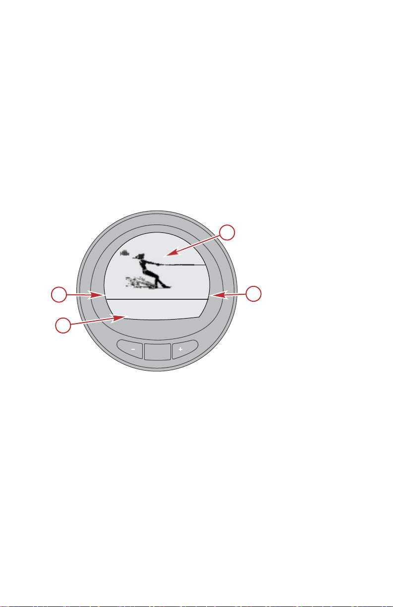
Power up: After the ignition is turned on, the splash screen will display the
name of the gauge, the level of the gauge, the image, and the version of the
software for approximately two seconds.
NOTE: The contents of the splash screen will change based on the level of
gauge purchased.
Example of a level 3 gauge
a - Name of gauge
b - Level of gauge
c - Image
d - Version of software
Lights: Adjusts the brightness and contrast of the gauge.
Buttons: The "MODE" button is used for selecting information screens. The "+"
and "–" buttons are used for setting engine speed for cruise control, launch
control, and setting gauge calibrations. To return to the previous screen, hold
the "MODE" button down for three to five seconds.
Cruise control: Sets and controls the speed of the engine for cruising.
Launch control: Controls the speed of acceleration from idle to cruise speed.
eng 1
Page 8
MODE
Sys Check
Battery
[ SKIP ]
Oil Psi
Water Psi
Water Temp
OK
OK
!
30266
a
b
c
d
e
Maintenance
GENERAL INFORMATION
Engine Guardian System: Monitors the critical sensors on the engine for any
early indication of problems. The system will respond to a problem by reducing
engine speed and alerting the operator to a potentially damaging situation.
Warning system: The system sounds the warning horn and displays the
warning "AL" in the right corner of the "Main Menu" screen. The alarm screen
will pop up with the "AL" in the upper right side of the screen and an alarm
information in the middle of the screen. For alarms with descriptive text, press
the "+" button for more information.
IMPORTANT: Optional sensors such as depth, fuel, paddle wheel, and steering
angle, should always be connected to the starboard engine when using
SmartCraft gauges version 4.0 or later.
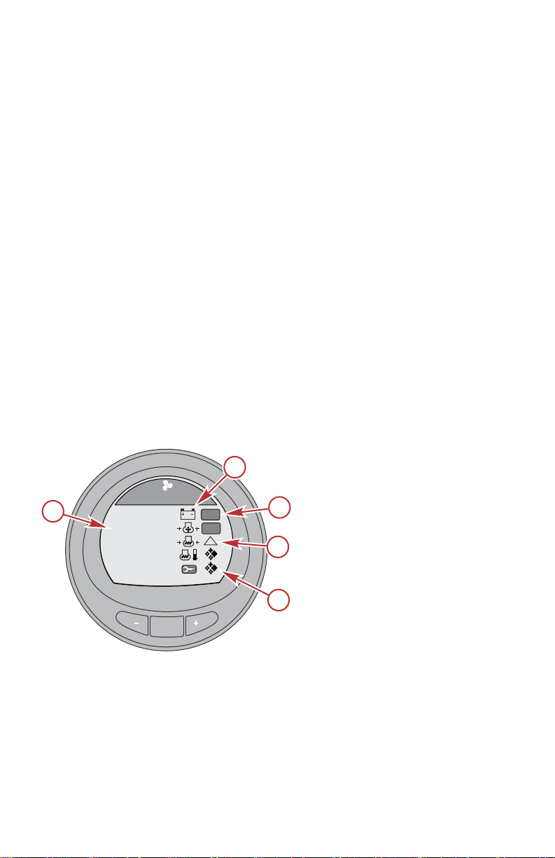
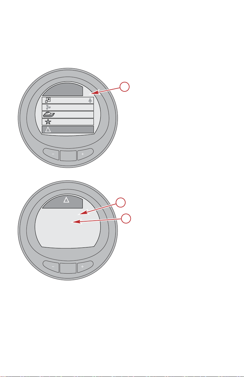
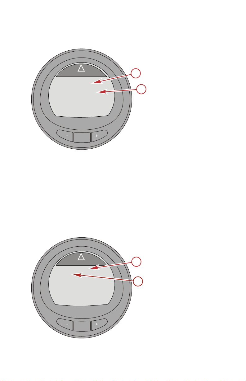
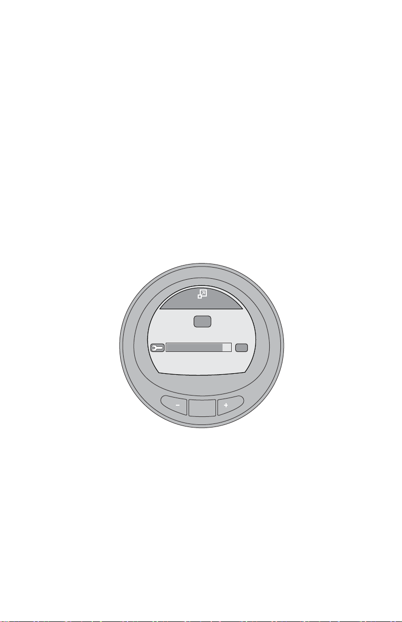
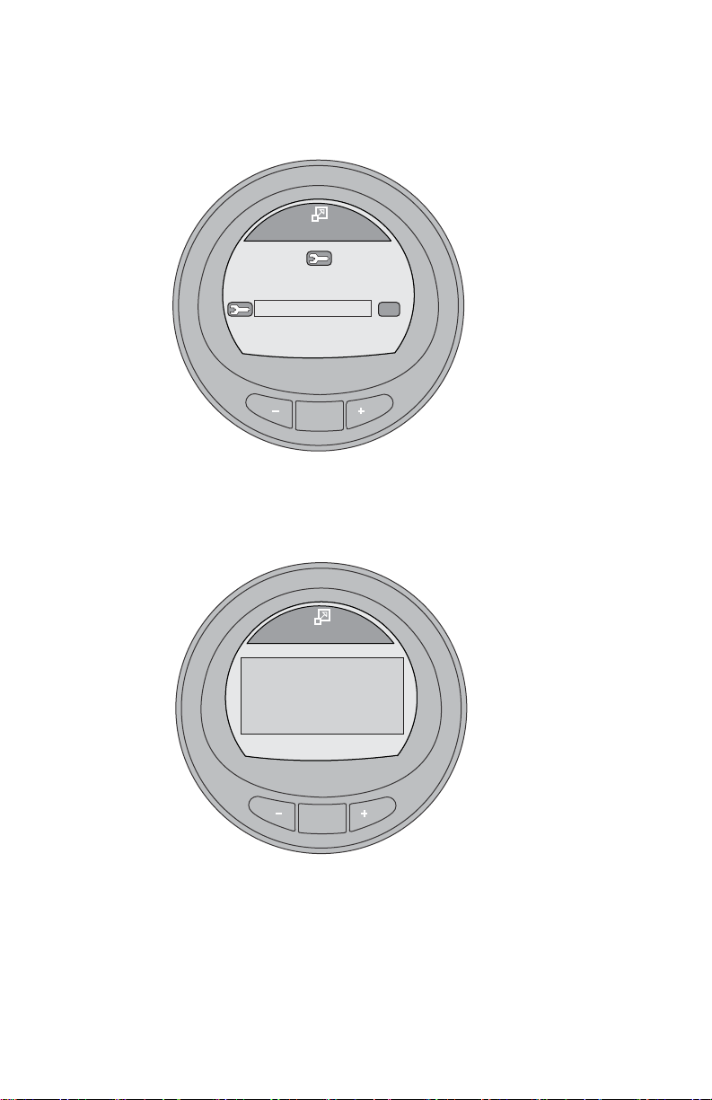
SYSTEM CHECK
• The system check screen will appear after the splash screen. This option
must be enabled to view it. Depending on the installed power package,
the system check screen will display the overall condition of the battery
and a few other sensor conditions that are important for that power
package. The component description will be displayed on the left side of
the monitor, its corresponding icon will be off‑center right, an icon in
motion to the right will indicate what is being checked. When the
component checks good, the icon in motion will change to "OK." If the
system check identifies a problem, the icon in motion will change to a
warning icon. You can bypass the system check by pressing the "MODE"
button to skip the check.
a - Component description
b - Corresponding icon
c - System check OK
d - System check warning
icon
e - Icon in motion
• After the system check is completed and no problem is identified, the
monitor screen reverts to the last screen that was visible before the key
switch was turned off. If a problem was identified, the alarm screen will be
displayed. Refer to Alarm Warnings.
2 eng
Page 9

30258
GENERAL INFORMATION
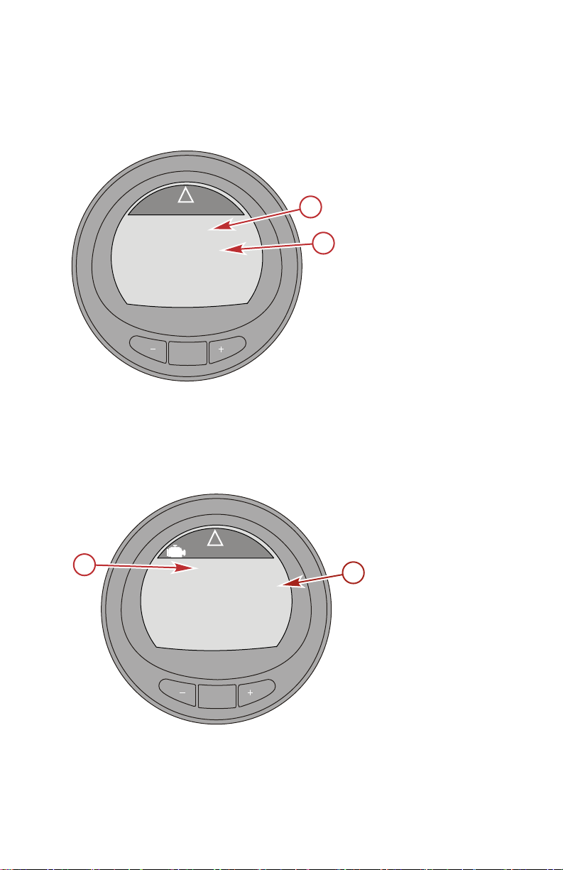
PRODUCTS WITH EMISSIONS CONTROL
After the ignition is turned on, the splash screen will display the name of the
gauge, the level of the gauge, and the version of the software for approximately
two seconds. In the upper left‑hand corner of the display, a small engine icon
will also be visible. The icon is an indicator that the power package has
emissions control onboard diagnostics, also known as OBD. The icon will only
be seen during the key up process unless a system fault is detected. When an
OBD fault is detected, the OBD icon will be displayed in the upper left‑hand
corner on all system screens.
OBD icon
MercMonitor Gateway Models Description
There are four MercMonitor Gateway gauge models available. All versions of
the MercMonitor will display only one engine. All versions are capable of
transmitting the engine data via NMEA 2000 (N2K); however, a Data Level 3
version will transmit up to four engines of N2K data.
• MercMonitor Base Model (Data Level 1) with eight NMEA 2000 gateway
in/out features
• MercMonitor RPM Smart Tow (Data Level 2) with 19 NMEA 2000
gateway in/out features
• MercMonitor Premier Kit (Data Level 3) with 23 NMEA 2000 gateway
in/out features
• MercMonitor Smart Tow Pro Kit (Data Level 3) with 23 NMEA 2000
gateway in/out features includes a GPS puck in the kit for accurate speed
based Smart Tow function
NOTE: Each of the above models incorporates the use of NMEA 2000 and
J1939 software interface that allows or controls access to other manufacturers
programs if available. Be sure to check with the manufacture for detailed
information on the features they offer.
eng 3
Page 10
GENERAL INFORMATION
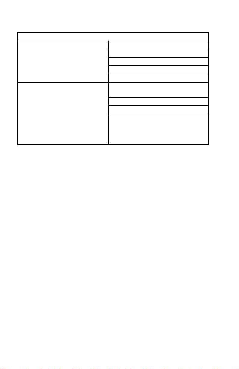
Level 1—Base Model (single engine, NMEA 2000 support selectable)
RPM
NMEA 2000 and J1939 in/out
supported
NMEA 2000 only in/out supported
Voltage
Oil pressure
Coolant temperature
Fuel tank level percent
Fluid level percent (fuel 2, oil, water,
waste)
Trim position
Water pressure
Check engine alarm
IMPORTANT: NMEA 2000/J1939 alarm
data is limited. Refer to the MercMonitor
display for descriptive fault text.
4 eng
Page 11
GENERAL INFORMATION
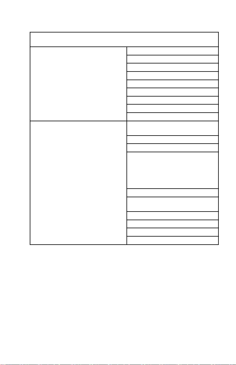
Level 2—RPM Smart Tow Model (single engine, NMEA 2000 support
selectable)
RPM
Voltage
Oil pressure
NMEA 2000 and J1939 in/out
supported
NMEA 2000 only in/out supported
Coolant temperature
Fuel tank level percent
Fuel flow
Engine hours
Boost pressure
Oil temperature
Fluid level percent (fuel 2, oil, water,
waste)
Trim position
Water pressure
Check engine alarm
IMPORTANT: NMEA 2000/J1939
alarm data is limited. Refer to the
MercMonitor display for descriptive
fault text.
Tabs
GPS speed/COG/latitude, longitude
(in only)
Depth
Seawater temperature
Paddle wheel speed
Pitot speed
eng 5
Page 12

GENERAL INFORMATION
Level 3—Smart Tow Pro Model with GPS puck (four or fewer engines, NMEA
2000 support selectable)
RPM
Voltage
Oil pressure
NMEA 2000 and J1939 in/out
supported
NMEA 2000 in/out supported (only)
Coolant temperature
Fuel tank level percent
Fuel flow
Engine hours
Boost pressure
Oil temperature
Fluid level percent (fuel 2, oil, water,
waste)
Trim position
Water pressure
Check engine alarm
IMPORTANT: NMEA 2000/J1939
alarm data is limited. Refer to the
MercMonitor display for descriptive
fault text.
Tabs
GPS speed/COG/latitude, longitude
(in only)
Depth
Seawater temperature
Paddle wheel speed
Pitot speed
Rudder angle
Gear pressure (Mercury Diesel)
Gear temperature (Mercury Diesel)
Fuel pressure
Capacity (English or metric)
6 eng
Page 13
GENERAL INFORMATION
Level 3—Gateway Premier (four or fewer engines, NMEA 2000 support
selectable) (includes RPM Smart Tow)
RPM
Voltage
Oil pressure
NMEA 2000 and J1939 in/out
supported
NMEA 2000 in/out supported (only)
Coolant temperature
Fuel tank level percent
Fuel flow
Engine hours
Boost pressure
Oil temperature
Fluid level percent (fuel 2, oil, water,
waste)
Trim position
Water pressure
Check engine alarm
IMPORTANT: NMEA 2000/J1939
alarm data is limited. Refer to the
MercMonitor display for descriptive
fault text.
Tabs
GPS speed/COG/latitude, longitude
(in only)
Depth
Seawater temperature
Paddle wheel speed
Pitot speed
Rudder angle
Gear pressure (Mercury Diesel)
Gear temperature (Mercury Diesel)
Fuel pressure
Capacity (English or metric)
MercMonitor Gateway Protocol Acceptance Description
Gateway is a software interface that allows or controls access to other
programs through a NMEA 2000 or J1939 protocol; a backbone for
communication to share information. The software is capable of transmitting
(TX) information to, and receiving (RX) information from various parameter
group number (PGN) products.
eng 7
Page 14
GENERAL INFORMATION
Gateway Modes
Transmit (TX) Receive (RX)
Transmits engine data to NMEA 2000/J1939
compatible display devices.
Base and RPM Smart Tow models require one
MercMonitor per engine.
Gateway Premier and Smart Tow Pro models
require only one MercMonitor per vessel to
transmit multiengine data to multifunction
displays (MFD) through the NMEA 2000/J1939
protocol.
The MercMonitor will display one engine only
regardless of the model (base, RPM Smart Tow,
Smart Tow Pro, Gateway Premier).
Mercury Engine Data to NMEA 2000 Capable Products
Signal PGN Name NMEA 2000 PGN Mode
Rated RPM Engine Parameter Static 127498/0x1F20A RX/TX
Coolant Pressure
Speed Over Water Speed 128259/0x1F503 RX/TX
RPM
Voltage
Coolant Temperature
Fuel Pressure
Fuel Level Fluid Level 127505/0x1F211 RX/TX
Fuel Tank Size Fluid Level 127505/0x1F211 RX/TX
Fuel Flow
Oil Pressure
Oil Temperature
Engine Parameters Rapid
Dynamic
Engine Parameters Rapid
Update
Engine Parameters Rapid
Dynamic
Engine Parameters Rapid
Dynamic
Engine Parameters Rapid
Dynamic
Engine Parameters Rapid
Dynamic
Engine Parameters Rapid
Dynamic
Engine Parameters Rapid
Dynamic
Receives data from NMEA
2000/J1939 compatible
engines.
Each engine requires its
own MercMonitor
regardless of the model
(base, RPM Smart Tow,
Smart Tow Pro, Gateway
Premier).
127489/0x1F201 RX/TX
127488/0x1F200 RX/TX
127489/0x1F201 RX/TX
127489/0x1F201 RX/TX
127489/0x1F201 RX/TX
127489/0x1F201 RX/TX
127489/0x1F201 RX/TX
127489/0x1F201 RX/TX
8 eng
Page 15
GENERAL INFORMATION
Mercury Engine Data to NMEA 2000 Capable Products
Signal PGN Name NMEA 2000 PGN Mode
Gear Temp Transmission Dynamic 127493/0x1F205 RX/TX
Gear Pressure Transmission Dynamic 127493/0x1F205 RX/TX
Boost Pressure
Trim position
Rudder Angle Rudder 127245/0x1F10D RX/TX
Depth Depth 128267/0x1F50B RX/TX
Depth Offset Depth 128267/0x1F50B RX/TX
Seawater Temp Environmental Parameters 130310/0x1FD06 RX/TX
Engine hours
Manufacturer ID
Alarm data Check Engine 127489/0x1F201 RX/TX
Tabs Small Craft Status 130576/0x1FE10 RX/TX
Course over Ground
Speed over Ground
GPS Position Position Rapid Update 129025/0x1F801 RX
Battery Battery Status 127508/0x1F214 RX/TX
Engine Parameters Rapid
Update
Engine Parameters Rapid
Update
Engine Parameters Rapid
Dynamic
Address Claim (0 x 90 =
Mercury)
COG and SOG Rapid
Update
COG and SOG Rapid
Update
127488/0x1F200 RX/TX
127488/0x1F200 RX/TX
127489/0x1F201 RX/TX
060928/0xEE00 RX/TX
129026/0x9F802 RX
129026/0x9F802 RX
eng 9
Page 16
GENERAL INFORMATION
Mercury Engine Data to J1939 Capable Products
Signal PGN Name J1939 PGN Mode
RPM
Voltage Vehicle Electrical Power 65271/0xFEF7 TX
Coolant Temperature Engine Temperature #1 65262/0xFEEE TX
Fuel Level Dash Display 65276/0xFEFC TX
Fuel Consumption Fuel Economy (Liquid) 65266/0xFEF2 TX
Fuel Flow Fuel Economy (Liquid) 65266/0xFEF2 TX
Oil Pressure
Boost Pressure Inlet/Exhaust Conditions 65270/0xFEF6 TX
Engine hours Total Engine Hours 65253/0xFEE5 TX
Manufacturer ID
Alarm data
(Diagnostic message
supported)
Line‑Line AC RMS Volt Generator Set Average 65030/0xFE06 RX/TX
AC RMS Frequency Generator Set Average 65030/0xFE06 RX/TX
Electronic Engine
Controller #1
Engine Fluid Level/Press
#1
Address Claim (0 x 90 =
Mercury)
Check Engine 65226/0xFECA TX
61444/0xF004 TX
65263/0xFEEF TX
61182/0xEEFE TX
Connection to a Non‑SmartCraft Network
The use of the MercMonitor on a non‑SmartCraft network application requires
the MercMonitor gateway set to "Receive." Failure to set the gateway to
"Receive" will cause numerous faults to appear that cannot be resolved.
Changing the gateway to "Receive" will clear the faults. The menu path to set
the gateway to "Receive" is: "Main Menu," > "Settings," > "Gateway," >
"Gateway."
Automatic Engine Detection Feature
The SmartCraft monitor has an automatic engine detection feature. This feature
automatically detects which engine type is used and configures the gauge to
match that engine type.
10 eng
Page 17

MODE
35915
AUTODETECT
ENGINE SMARTSCREEN
PRESS MODE TO START
GENERAL INFORMATION
The first power up of the gauge, or after a reset all to factory default, the gauge
will display "AUTODETECT." Press the "MODE" button to start the automatic
engine detection feature and the gauge will determine the engine type. This will
preset the data monitoring screens to make the initial setup easier.
If the gauge shows a warning of "NO STARBOARD ENGINE" or "MULTIPLE
STARBOARD ENGINES," the engine location (port and starboard) must be
selected by an authorized dealer equipped with the computer diagnostic
system (CDS) tool.
Alarm Warnings
IMPORTANT: Alarm warnings are only available on the MercMonitor screen.
NMEA 2000/J1939 gateway is limited to seven alarm functions.
NOTE: Descriptive text alarm warning screens are displayed with Gen I (2007)
engines and newer and universal fault codes will be displayed on all 4.5L, 6.2L,
and SeaPro engines.
eng 11
Page 18
MODE
Main Menu
AL
Full Screens
Favorites
Vessel
Alarms
!
Propulsion / ST
MODE
Alarms
AL
!!!!
HELM 1
<Wheel Fault>
[ EXIT ]
[ MORE ]
a
b
c
58122
GENERAL INFORMATION
When a problem is detected, the "AL" alarm appears and a pop‑up window with
the alarm location and information will be displayed. The faulty component or
warning is described in the text. Press the "+" button for more information. This
screen gives a detailed description of the fault text. Press the "+" button to view
the required corrective action.
a - Flashing "AL" alarm
b - Source of helm alarm
c - Component
The alarm message will stay displayed until the "–" button is pressed. This
action will exit the warning screen. If there are multiple alarms, press the
"MODE" button to view the next warning display.
If universal fault codes are enabled, engines and helms that support universal
fault codes will send a fault number instead of descriptive text. All other engines
and helms will send descriptive text. When universal fault codes are disabled,
all engines and helms will send descriptive text.
12 eng
Page 19
MODE
Alarms
AL
[ EXIT ]
[ NEXT ]
!
STBD
3152 - 16
a
b
58123
MODE
Alarms
AL
[EXIT]
[MORE]
b
[NEXT]
STBD
<Ignition>
!
a
58086
GENERAL INFORMATION
NOTE: Refer to the
"Universal Fault Code"
in the "Settings" menu to enable
or disable this feature.
a - Fault location
b - Universal fault code
If a problem can cause immediate engine damage, the Engine Guardian
System will respond to the problem by limiting engine power. Immediately
reduce the throttle speed to idle and refer to the warning messages. If the
"MODE" button is pressed to display a different screen, the flashing alarm
signal "AL" will appear in the upper right corner to indicate there still is a
problem. Refer to the appropriate service manual for further explanation of the
problem and the correct action to take.
VIEWING DESCRIPTIVE TEXT
1. When a problem is detected, the "AL" alarm will flash on the display and a
pop‑up window displays the system where the fault is located, and what
component is identified as a problem.
a - Fault location
b - Component
eng 13
Page 20

MODE
Alarms
AL
[EXIT]
[BACK]
[NEXT]
STBD
!
<See Dealer Soon>
58088
MODE
Alarms
AL
[EXIT]
[MORE]
[NEXT]
STBD
!
a
<Ignition coil is not
working properly>
b
58087
GENERAL INFORMATION
2. Press the "+" button to view the descriptive warning text. The identified
component expands to show additional text describing the fault.
a - Fault location
b - Additional text
describing the fault
3. Press the "+" button to view the descriptive recommended actions to take.
4. Press the "+" button to go back to the component identification or press
the "MODE" button to view the next alarm.
5. Press the "–" button to exit the alarm screen.
14 eng
Page 21
MODE
Alarms
AL
[ EXIT ]
[ NEXT ]
!
STBD
3152 - 16
a
b
58123
MODE
Alarms
AL
[EXIT]
[MORE]
b
!
STBD
<Engine Sensor>
a
58097
GENERAL INFORMATION
UNIVERSAL FAULT CODES DISPLAYED
1. When universal fault codes are enabled and a problem is detected, the
"AL" alarm will flash on the display and a pop‑up window displays the
system where the fault is located and the universal fault code.
a - Fault location
b - Universal fault code
2. Press the "+" button to view the next alarm.
3. Press the "–" button to exit the alarm screen.
EMISSION CONTROL ALARM WARNINGS
1. The screen displays the fault location and a description of the faulty
component. Press the "+" button for more information.
a - Fault location
b - Component
eng 15
Page 22

MODE
Alarms
AL
[EXIT]
[ACTION]
!
STBD
<Exhaust Oxygen
Sensor is not working
properly>
a
b
58102
GENERAL INFORMATION
2. A detailed description of the faulty component is explained. Press the "+"
button for information on a corrective action.
a - Detailed description
of the fault
component
b - "+" button to show
corrective action
NMEA 2000/J1939 GATEWAY ALARMS
• Check Engine
• Over Temperature
• Water in Fuel (WIF)
• Water Pressure
• Low Oil Pressure
• Low System Voltage
• Engine Communication Error
Identifying and Using the Screen Categories
The monitor displays engine and vessel information through various screens.
These screens can be selected to be favorites which will flash on the screen for
a specific amount of time. The "Settings" menu option allows the screens to be
turned off or on. The "Settings" menu option also allows the calibration of the
monitor to the various different sensors like the fuel, trim, tabs, and steering to
name a few.
•
"Propulsion" contains all screens related to the propulsion system; trim,
engine performance, troll control, and Smart Tow.
•
"Vessel" contains screens related to fuel use, tank levels, tabs, GPS
data, steering position, and other items such as generators.
•
"Full Screens" displays various information from the propulsion and
vessel menu in large, easy to read letters. The full screen menu also
displays some information as "Tri Data." There are five "Tri Data" screens.
16 eng
Page 23

GENERAL INFORMATION
•
"Favorites" are specific screens selected by the operator to be reviewed
quickly. The favorites will remain on the screen for a specific amount of
time. This time can be one second up to 30 seconds or turned "OFF" to
advance manually through the screens. A total of nine screens can be
selected from the "Propulsion" menu, "Vessel" menu, or "Full Screens"
menu. Press and hold the "–" and "+" buttons down at the same time for
three to five seconds to add the screen to the favorites menu.
•
"Alarms" displays information on the location, identifies, and advises a
corrective action to take for all warning alarms. If available, while in the
"Alarms" category, press the "+" button for more detailed descriptive text
about the fault. Press the "+" button again to review the recommended
corrective action to take. Press the "MODE" button to review the next
fault, or press the "–" button to exit the "Alarms" screen.
•
"Settings" allows the user to turn on and off screens, select a type of
measurement (knots, kilometers, miles), select a screen color, adjust the
contrast and brightness of the screen, select a digital or analog clock
display, adjust and correct various different sensor parameters (tanks,
trim, tabs), activate a GPS interface with the gauge, give the gauge a
specific name (up to 14 characters), enable universal fault codes, and
reset the gauge to the factory default settings.
eng 17
Page 24
[ NEXT ]
Speed
[ EXIT ]
36681
0.0
MPH
[OPTION]
RPM AT SPEED PEAK MPH
0.0
0
PDL
[ NEXT ]
Depth
[ EXIT ]
36685
126
FT
39290
[ NEXT ]
Coolant Temp
[ EXIT ]
0
177
200
F
o
FULL SCREENS
Full Screens Features and Options
The Full Screens menu displays large icon vessel and propulsion data in
addition to Tri Data screens. Several screens show a minimum and maximum
reference with an arrow directing your attention to the current value displayed
within the screen. The minimum and maximum reference limits are the same
minimum and maximum limits that are shown on a System Link gauge.
Additionally, a number of screens allow the resetting of peak RPM or speed
data. The Full Screens and Tri Data screen must be turned on—Yes for these
screens to be active in the Full Screens menu. The menu path to turn the Full
Screens data on is: Main Menu, > Settings, > Screens, > Full Screens. The
menu path to select the Tri Data information is: Main Menu, > Settings, >
Screens, > Tri Data.
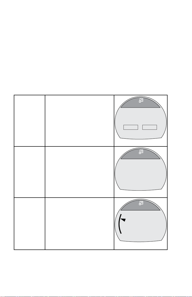
Displays large numbers for the
vessel speed through the
Speed
available sensor, the peak speed,
and the peak RPM at speed. The
peak values can be reset.
Depth
Coolant
Temperature
18 eng
Displays the water depth in large
numbers.
Displays the engine coolant
temperature in large numbers and
on a bar graph.
Page 25
Clock
[ NEXT ]
Clock
[ EXIT ]
36702
23:15
39751
[ NEXT ]
Oil Temp
[ EXIT ]
0
177
300
F
o
[ NEXT ]
Fuel Pressure
[ EXIT ]
36697
42.8
PSI
39752
[ NEXT ]
Oil Press
[ EXIT ]
0
38
100
PSI
FULL SCREENS
Displays the time in large
numbers. Can be displayed as 24
hour or 12 hour.
Oil
Temperature
Fuel Pressure
Oil Pressure
Displays the engine oil
temperature in large numbers and
on a bar graph.
Displays the engine fuel pressure
in large numbers.
Displays the engine oil pressure
in large numbers and on a bar
graph.
eng 19
Page 26
40531
[ NEXT ]
Water Press
[ EXIT ]
0
15.2
30
PSI
39286
[ NEXT ]
Battery
[ EXIT ]
8
13.8
16
V
43149
[ NEXT ]
Air Temp
[ EXIT ]
87
F
O
[ EXIT ]
Maintenance
Scheduled Maintenance
OK
OK
GEN. MAINTENANCE
50377
FULL SCREENS
Water
Pressure
Battery
Air
Temperature
Maintenance
Displays the engine water
pressure in large numbers and on
a bar graph.
Displays the battery voltage level
in large numbers and on a bar
graph.
Displays the air temperature in
large numbers.
Estimates the amount of run time
the engine accumulated since the
last scheduled maintenance.
Normal scheduled maintenance
for the engine is 100 hours. The
maintenance screen shows a bar
graph approximating the amount
of time remaining before a
scheduled maintenance is
required. The maintenance
screen must be turned on for this
screen to be displayed.
20 eng
Page 27
Tri Data
[ NEXT ]
Clock
[ EXIT ]
36678
Speed
Sea
- - : - -
- - - -
F
o
0.0
MPH
[ NEXT ]
RPM
[ EXIT ]
36680
0
RPM
[OPTION]
RPM AT SPEED PEAK MPH
0.0
0
67340
Active Trim
ACTIVE TRIM PROFILE
2
[ DOWN ] [ NEXT ] [ UP ]
67345
Sport Exhaust
SPORT EXHAUST
ON
[ DOWN ] [ NEXT ] [ UP ]
RPM
Active Trim
FULL SCREENS
Displays vessel and propulsion
data selected and arranged by the
user. Up to five tri data screens
can be customized by the user.
Displays large numbers for the
engine RPM, shows the peak
speed, and the peak RPM at
speed. The peak values can be
reset.
Displays the Active Trim minor
profile, and allows for the
adjustment up or down of the
profile characteristics. The major
profile must be selected in the
Active Trim screen in the Settings
menu.
Sport Exhaust
RESETTING PEAK VALUES
The "RPM" and "Speed" full screens will record and store the vessel peak
speed and the RPM at that peak speed. These peak values can be reset to
capture new RPM and speed data.
eng 21
Displays the status of the Sport
Exhaust sound control for engines
equipped with this option.
Page 28
MODE
36704
[ NEXT ]
Speed
[ EXIT ]
20.8
MPH
[OPTION]
RPM AT SPEED PEAK MPH
58.6
6120
PDL
MODE
36706
Speed
[ YES ]
20.8
MPH
[ NO ]
RPM AT SPEED PEAK MPH
58.6
6120
PDL
Reset Peak Values ?
FULL SCREENS
1. While the "RPM" or "Speed" full screen is visible, press the "+" button to
open the reset option.
2. A pop‑up window will appear asking if the peak values should be reset
("Reset Peak Values?").
3. Press the "+" button if you do not want to reset the values "(NO)."
4. Press the "–" button if you want to reset the values "(YES)."
5. When the selection is "(YES)," the pop‑up window will close and the new
22 eng
data will populate the peak values immediately.
Page 29
MODE
50376
[ EXIT ]
Maintenance
Scheduled Maintenance
OK
OK
GEN. MAINTENANCE
FULL SCREENS
Maintenance Screen
Some 4‑Stroke power package models can estimate the amount of time the
engine has run since the last scheduled maintenance. Normal scheduled
maintenance for the engine is every 100 hours. The maintenance screen
shows a bar graph approximating the amount of time remaining before a
scheduled maintenance is required. When the maintenance screen is reset, the
bar graph will change to 100 hours before the next scheduled maintenance.
The maintenance screen must be turned on for this screen to be displayed.
Your owner's manual maintenance schedule should be followed regardless of
what the gauge displays. To turn this feature on, refer to Section 7: Settings—
Turning the Screens On.
1. While in the Main Menu, use the "–" or "+" button to highlight the Full
Screens option. Press the MODE button to open the Full Screens option.
2. Press the MODE button to page through the screens.
3. The Maintenance screen will show a bar graph approximating the amount
of time remaining before a scheduled maintenance is required. Press the
MODE button to exit to the Maintenance screen.
eng 23
Page 30
MODE
Maintenance
Perform Maintenance
OK
GEN. MAINTENANCE
50379
[BACK] [RESET]
MODE
[ NO ]
Maintenance
[ YES ]
Engine Oil Life
0
89%
HAS SCHEDUALED
MAINTENANCE BEEN
PERFORMED?
50389
FULL SCREENS
4. If the bar graph is not visible, the engine scheduled maintenance has
passed 100 hours and the screen will change to Perform Maintenance.
Press the "+" button to begin the reset procedure.
5. A window will pop up asking HAS SCHEDULED MAINTENANCE BEEN
PERFORMED? Press the "+" button—NO, to return to the Maintenance
screen, or press the "–" button—YES, to reset the scheduled maintenance
screen.
24 eng
Page 31

MODE
Maintenance
Scheduled Maintenance
OK
GEN. MAINTENANCE
[EXIT] [MENU][NEXT]
50391
FULL SCREENS
6. After pressing the "–" button—YES, to reset the scheduled maintenance
screen, the bar graph will reset to 100 hours. Press the "–" button to exit
the Maintenance window and return to the Main Menu, or press NEXT to
exit the maintenance screen to the next full screen, or press MENU to
repeat the scheduled maintenance reset process.
eng 25
Page 32

Troll Control
[DOWN]
36114
ON
[MODE]
[ UP ]
MUST BE IN IDLE
SET
MPH
MPH
PDL
4.5
4.8
OFF
RPM
Speed
Coolant Temp
Water Press
RPM
MPH
PDL
o
C
Bar
2050
12.7
195
8.36
Water
36081
[ EXIT ] [ NEXT ]
RPM
Speed
Oil Temp
Oil Press
RPM
MPH
PDL
o
C
Bar
2050
12.7
205
2.84
Oil
36085
[ EXIT ] [ NEXT ]
67346
Oil Level
[ EXIT ] [ NEXT ]
Oil Level is LOW!
Check Oil.
PROPULSION MENU
Using Propulsion Screens
The Propulsion menu screens will display information about the boat propulsion
systems. Screens that are available in the Propulsion menu may vary
according to the engine type.
Available Propulsion Screens
Displays an icon to indicate the
troll control is turned on or off. It
Troll Control
Water
can be controlled with the vessel
speed through the active sensor
or with the engine RPM.
Displays the engine RPM, vessel
speed through the active sensor,
coolant temperature, and water
pressure.
Displays the engine RPM, vessel
Oil Information
speed through the active sensor,
oil temperature, and oil pressure.
The Oil Level screen displays the
engine oil level status as Oil
Level OK or Oil Level is LOW.
The engine oil level status is only
Oil Level
displayed upon key on, before
the engine is started. During
operation of the engine this data
26 eng
screen will not actively monitor
the engine oil level.
Page 33

Peak Speed
RPM
Speed
Peak Speed
RPM @ Speed
RPM
MPH
PDL
RPM
2050
12.7
58
5800
MPH
[OPTION]
Peak Speed
36087
[ EXIT ] [ NEXT ]
Fuel Pressure
[ EXIT ] [ NEXT ]
RPM
Fuel Press
Fuel Flow
RPM
BAR
2050
12.7
8
L/H
36095
[ EXIT ] [ NEXT ]
RPM SYNCH
PORT
3750
42334
RPM
3250
STBD
STBD
[ EXIT ] [ NEXT ]
Fuel Flow
Fuel Used
L/H
12.7
8.0
L
[OPTION]
36099
Fuel Pressure
RPM Synch
PROPULSION MENU
Displays the engine RPM, vessel
speed through the active sensor,
the peak vessel speed, and what
the engine RPM was at that peak
vessel speed. The peak values
can be reset.
Displays the engine RPM, fuel
pressure, and amount of fuel that
is currently used per hour.
Displays the engine RPM and
color band indicating to increase
or decrease the RPM to
synchronize the engines.
Displays the engine location the
gauge is connected to, the
amount of fuel that is currently
used per hour, and the amount of
fuel that has been used. The
Fuel Used
amount of fuel used can be reset.
STBD (starboard engine)
PORT (port engine)
CNTR (center engine)
STB2 (starboard center)
PRT2 (port center)
eng 27
Page 34

Double
42336
0
1
2
3
4
5
6
7
8
3280
RPM
Speed(MPH)
19.8
42338
0
1
2
3
4
5
6
7
8
RPM
X
1000
42339
0
10
20
30
40
50
60
70
80
Speed(MPH)
PDL
Volts/Hours
[ EXIT ] [ NEXT ]
Hours
Battery
H
12.7
13.2
V
RPM
RPM
3250
36102
Screens
PROPULSION MENU
The double screen displays two
selected data options on an outer
and inner display. The outer data
will be displayed as a bar graph
with a small window that moves
with the bar graph leading edge.
The inner data will be displayed
as numbers. Options that can be
selected are; "RPM," "Speed,"
"Coolant Temp," "Oil Temp,"
"Seatemp," "Water Press," "Oil
Press," "Fuel Flow," "Fuel,"
"Battery," and "Depth."
Analog
Tachometer
Displays the engine RPM with a
sweeping pointer.
Displays the vessel speed with a
Analog
Speedometer
sweeping pointer. Two different
ranges are available; 0–80 or 0–
120 as knots, kilometers per
hour, or miles per hour.
Displays the total hours the
Volts/Hours
engine has run, the battery
current state of charge, and the
engine RPM.
28 eng
Page 35

Boost
Boost Pressure
[ EXIT ] [ NEXT ]
SPEED
12.7
MPH
PDL
RPM
3250
36106
-2 +20
BAR
[ EXIT ] [ NEXT ]
TRIM SYNCH
PORT
0.0
42340
Trim
3.2
STBD
Trim
[ EXIT ] [ NEXT ]
36109
10
0
25
9.5
Trim/Tab
[ EXIT ] [ NEXT ]
36527
10
0
25
25
STBD
PORT
0.0 0.0
Pressure
Trim Synch
(Dual Engine)
Trim
PROPULSION MENU
Displays the engine RPM, the
vessel speed through the active
sensor, and the amount of
manifold pressure.
Displays a color band indicating
to increase or decrease the trim
to synchronize the engines trim
location.
Displays the position of the trim
with a moving propeller icon and
displays the trim position number
relative to the propeller icon.
Trim/Tab
eng 29
Displays the position of the port
and starboard tabs with a moving
tab icon and the trim position with
a moving propeller icon. A
number relative to the position of
the icons is also displayed in the
lower portion of the screen.
Page 36

Smart Tow
SmartTow
36125
[DOWN]
[MODE]
[ UP ]
ON
+ / - TO ENGAGE
SET
RPM
ACT
RPM
1000
850
OFF
PROFILE : Cruise
RPM
67201
Active Trim
[ OFF ] [ NEXT ]
ACTIVE TRIM FEATURE
ON
[ ON ]
67287
Active Trim
[ DOWN ] [ NEXT ]
ACTIVE TRIM PROFILE
2
[ UP ]
67200
Sport Exhaust
[ EXIT ] [ NEXT ]
SPORT EXHAUST
ON
[ OFF ]
Active Trim
Active Trim
Profile
PROPULSION MENU
Displays an icon to indicate
Smart Tow is turned on or off,
selects cruise control or launch
control, selects the launch control
level one through five, allows the
creation of up to eight
customized launch levels, and
selects if Smart Tow is based on
RPM or speed.
The Active Trim screen shows
the status of Active Trim, either
ON or OFF. Pushing the "+"
button will enable the Active Trim
feature.
There are 5 Active Trim profiles.
Pressing the "–" or "+" buttons
will navigate either [UP] or
[DOWN] through the profiles.
The Sport Exhaust feature allows
the operator to change the sound
of the outboard idle relief exhaust
Sport Exhaust
volume. Enabling the Sport
Exhaust feature opens an
exhaust passage, allowing a
more deep exhaust sound at idle.
30 eng
Page 37

MODE
36115
Troll Control
[DOWN]
ON
[MODE]
[ UP ]
MUST BE AT IDLE
MIN
RPM
ACT
RPM
563
550
OFF
b
c
a
RPM
MODE
36117
Troll Control
[DOWN]
[MODE]
[ UP ]
+/- TO DISENGAGE
OFF
ON
b
a
MIN
RPM
ACT
RPM
563
550
RPM
PROPULSION MENU
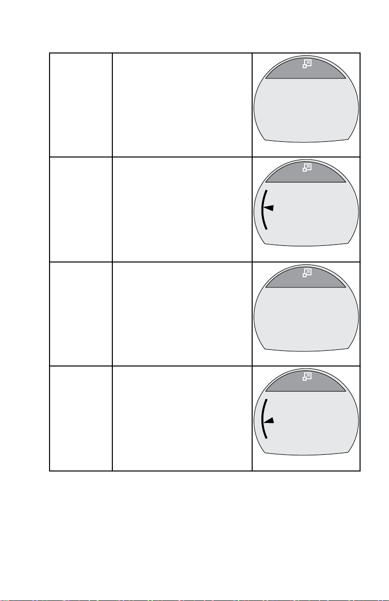
Troll Control
The Troll Control screen displays an icon to indicate the troll control is turned
on or off, the engine RPM, or the vessel speed. Troll control can be controlled
by the vessel speed or the engine RPM.
a - Icon indicating troll control
is turned off
b - Set RPM
c - Actual engine RPM
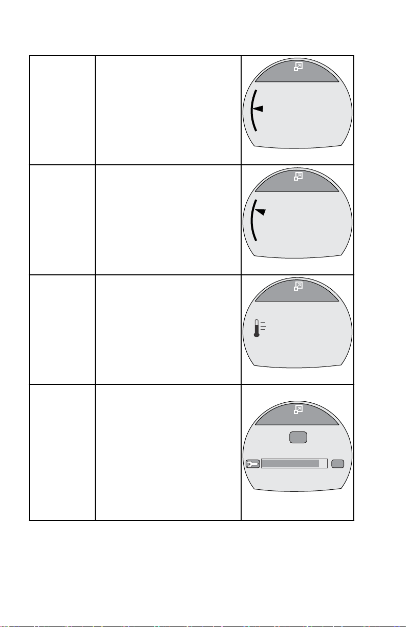
TURNING TROLL CONTROL ON AND OFF
1. Ensure the engine is running and the remote control is in gear at idle.
2. To turn the troll control on, press the "–" and "+" buttons at the same time.
The troll control ON icon will be highlighted and the information below the
RPM will change to +/– TO DISENGAGE.
a - Troll control ON icon
b - +/– TO DISENGAGE
3. Press the "–" or "+" button to decrease or increase the engine RPM.
NOTE: The minimum RPM and the maximum RPM will depend on the power
package application.
eng 31
Page 38

MODE
36118
Troll Control
[DOWN]
[MODE]
[ UP ]
+/- TO ENGAGE
OFF
ON
b
a
MIN
RPM
ACT
RPM
563
550
RPM
36529
Troll Control
[DOWN]
ON
[MODE]
[ UP ]
SET
MPH
MPH
PDL
4.5
4.8
OFF
+/- TO ENGAGE
ACT
SPEED
Troll Control
[DOWN]
ON
[MODE]
[ UP ]
MIN
RPM
ACT
RPM
563
550
OFF
RPM
+/- TO ENGAGE
a
b
PROPULSION MENU
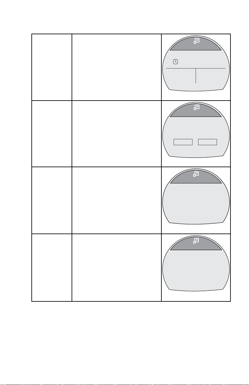
4. To turn the troll control off, press the "–" and "+" buttons at the same time,
or move the remote control handle into neutral. The troll control OFF icon
will be highlighted and the information below the RPM will change to +/–
TO ENGAGE.
a - Troll control OFF icon
b - +/– TO ENGAGE
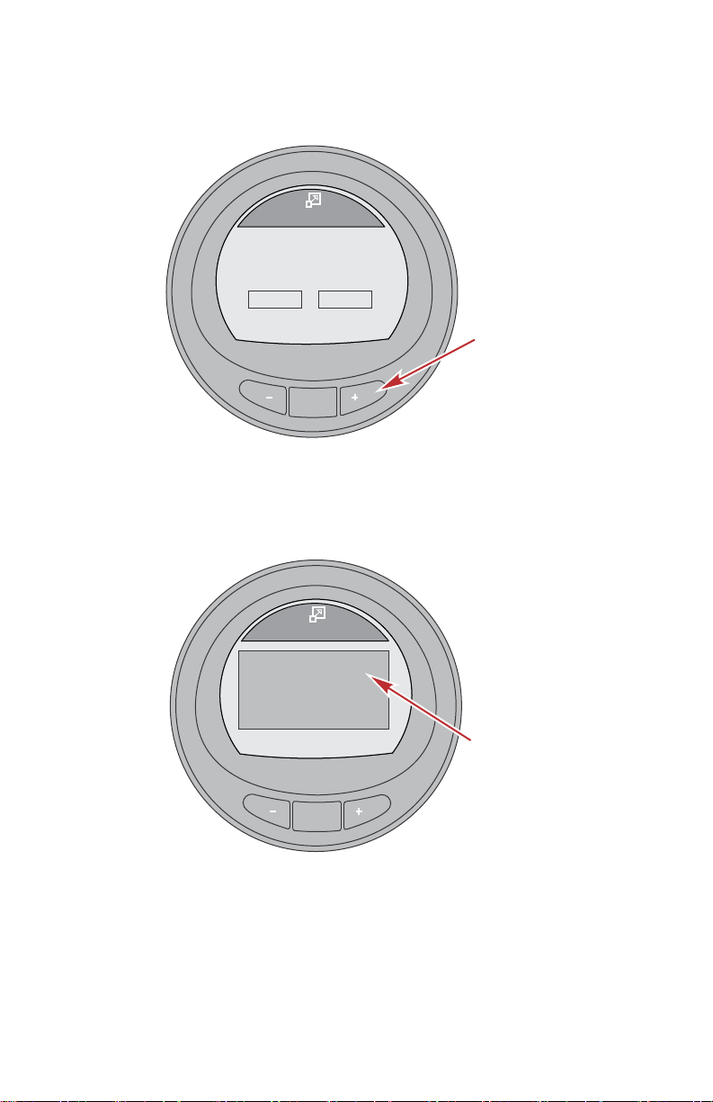
CHANGING THE TROLL CONTROL MODE OF CONTROL
The troll control function can be controlled with the engine RPM or the vessel
speed. To use the vessel speed to control the troll function, a paddle wheel
must be installed. Using the engine RPM to control the troll function will cause
the vessel speed to vary based on the conditions the vessel encounters: wind,
waves, or current. Using the vessel speed to control the troll function will cause
the engine RPM to fluctuate more, based on the conditions the vessel
encounters: wind, waves, or current. Changing the troll control mode can be
done when the troll control is turned on or off.
1. While the troll control screen is visible, press and hold the MODE button
until the screen changes mode.
2. Press the "–" or "+" button to change the speed. The engine RPM will
32 eng
a - RPM mode
b - Speed mode
react to the selected speed when the troll control is engaged.
Page 39

36530
Troll Control
[DOWN]
ON
[MODE]
[ UP ]
SET
MPH
MPH
PIT
4.5
4.8
OFF
ACT
SPEED
PADDLE REQUIRED
MODE
36103
RPM
Speed
Coolant Temp
Water Press
RPM
MPH
PDL
o
C
Bar
2050
12.7
195
8.36
Water
[ EXIT ] [ NEXT ]
a
b
c
d
PROPULSION MENU
3. To change back to the RPM mode, press and hold the MODE button until
the screen changes from speed mode to the RPM mode.
4. If there is no paddle wheel installed on the vessel, the speed mode of
control will show text below the ACT SPEED window indicating a paddle
wheel is required—PADDLE REQUIRED.
Water Screen
The Water screen displays the engine RPM, vessel speed through the active
sensor, coolant temperature, and water pressure.
a - RPM
b - Vessel speed
c - Coolant temperature
d - Water pressure
eng 33
Page 40

MODE
67204
Oil Level
[ EXIT ] [ NEXT ]
Oil Level OK
MODE
36105
RPM
Speed
Oil Temp
Oil Press
RPM
MPH
PDL
o
C
Bar
2050
12.7
205
2.84
Oil
[ EXIT ] [ NEXT ]
a
b
c
d
PROPULSION MENU
Oil Information
The Oil screen displays the engine RPM, vessel speed through the active
sensor, oil temperature, and oil pressure.
a - RPM
b - Vessel speed
c - Oil temperature
d - Oil pressure
Oil Level
NOTE: The engine oil level data screen may require additional components to
be installed on the engine. Review the operation manual that came with your
power package or consult your authorized Mercury dealer to determine if the
proper equipment is installed on the engine.
The Oil Level screen displays the engine oil level status as Oil Level OK or Oil
Level is LOW. The engine oil level status is only displayed upon key on, before
the engine is started. During operation of the engine this data screen will not
actively monitor the engine oil level.
34 eng
Oil level is OK reading
Page 41

MODE
67289
Oil Level
[ EXIT ] [ NEXT ]
Oil Level is LOW!
Check Oil.
MODE
36089
RPM
Speed
Peak Speed
RPM @ Speed
RPM
MPH
PDL
RPM
2050
12.7
58
5800
MPH
[OPTION]
Peak Speed
[ EXIT ] [ NEXT ]
PROPULSION MENU
Oil level is low reading
Peak Speed
The Peak Speed screen displays the engine RPM, vessel speed through the
active sensor, the peak vessel speed, and what the engine RPM was at that
peak vessel speed. The peak values information will automatically update when
the recorded values are exceeded.
RESET PEAK VALUES
The peak values can be reset to record new information.
1. Press the "+" button to open the option to reset the peak values.
eng 35
Page 42

MODE
36092
RPM
Speed
Peak Speed
RPM
MPH
PDL
RPM
2050
12.7
58
5800
MPH
[ NO ]
Peak Speed
[ YES ]
Reset Peak Values ?
MODE
36093
Fuel Pressure
[ EXIT ] [ NEXT ]
RPM
Fuel Press
Fuel Flow
RPM
BAR
2050
12.7
8
L/H
a
b
c
PROPULSION MENU
2. Press the "–"button ("YES") or "+" button ("NO") to reset the peak values.
The screen will return to the Peak Speed screen.
Fuel Pressure
The Fuel Pressure screen displays the engine RPM, fuel pressure, and amount
of fuel that is currently used per hour. The fuel flow is calculated by the PCM/
ECM.
a - RPM
b - Fuel pressure
c - Fuel flow
36 eng
Page 43

MODE
42342
[ EXIT ] [ NEXT ]
RPM SYNCH
PORT
3750
RPM
3250
STBD
a
b
c
MODE
36097
STBD
[ EXIT ] [ NEXT ]
Fuel Flow
Fuel Used
L/H
12.7
8.0
L
a
b
[OPTION]
c
PROPULSION MENU
RPM Synchronize
The RPM SYNCH screen displays the engine RPM and a color band that
expands under the engine with the lower RPM. The color band will decrease in
size as the engine RPM's near synchronization.
a - Port engine RPM
b - Starboard engine RPM
c - Color band indicating
starboard engine RPM
is low
Fuel Used
The engine location fuel used screen shows the engine location the gauge is
connected to in the upper part of the screen, the amount of fuel that is currently
used per hour, and the amount of fuel that has been used for that particular
engine. The amount of fuel used can be reset.
a - Engine location gauge is
connected to
b - Fuel flow
c - Fuel used
FUEL USED RESET
1. Press the "+" button to open the Fuel Used reset option.
eng 37
Page 44

MODE
36098
STBD
[ YES ]
Fuel Flow
Fuel Used
L/H
12.7
8.0
L
[ NO ]
Fuel Used Reset ?
MODE
42343
0
1
2
3
4
5
6
7
8
3280
RPM
Speed(MPH)
19.8
b
a
PROPULSION MENU
2. Press the "–" button ("YES") to reset the fuel used, or the "+" button
("NO") to return to the fuel use per engine location screen.
Double Screen
The double screen displays two selected data options on an outer and inner
display. The outer data will be displayed as a bar graph with a small window
that moves with the bar graph leading edge. The inner data will be displayed as
numbers. Options that can be selected are; RPM, Speed, Coolant Temp, Oil
Temp, Seatemp, Water Press, Oil Press, Fuel Flow, Fuel, Battery, and Depth.
There are five double screens available.
a - Moving window showing
the engine RPM
b - Vessel speed
38 eng
Page 45

MODE
42345
0
1
2
3
4
5
6
7
8
RPM
X
1000
a
MODE
42346
0
10
20
30
40
50
60
70
80
Speed(MPH)
PDL
a
PROPULSION MENU
Analog Tachometer
The analog tachometer displays the engine RPM with a sweeping pointer,
simulating a mechanical analog tachometer.
a - Sweeping pointer
Analog Speedometer
The analog speedometer displays the vessel speed with a sweeping pointer,
simulating a mechanical analog speedometer. Two speedometer scales are
available: 0–80 and 0–120.
a - Sweeping pointer
eng 39
Page 46

MODE
36101
Volts/Hours
[ EXIT ] [ NEXT ]
Hours
Battery
H
12.7
13.2
V
a
b
c
RPM
RPM
3250
MODE
36107
Boost Pressure
[ EXIT ] [ NEXT ]
SPEED
12.7
MPH
PDL
RPM
3250
-2 +20
BAR
a
b
c
PROPULSION MENU
Volts/Hours
The Volts/Hours screen displays the total hours the engine has run, the battery
current state of charge, and the engine RPM.
a - Total engine hours
b - Battery state of charge
c - RPM
Boost Pressure
The Boost Pressure screen displays the engine RPM, the vessel speed through
the active sensor, and the amount of manifold pressure.
a - RPM
b - Vessel speed
c - Manifold pressure
40 eng
Page 47

MODE
42348
[ EXIT ] [ NEXT ]
TRIM SYNCH
PORT
0.0
Trim
3.2
STBD
a
b
c
MODE
33230
Trim
[ EXIT ] [ NEXT ]
10
0
25
9.5
a
b
PROPULSION MENU
Trim Synchronize
The Trim Synch screen displays a color band indicating to increase or
decrease the trim to synchronize the engines trim location. The numbers are a
point of reference, relating to the position of the trim outside of the
synchronization.
a - Port engine trim point
of reference
b - Color band
c - Starboard engine trim
point of reference
Trim Screen
The Trim screen displays the position of the trim with a moving propeller icon
and displays the trim position number relative to the propeller icon.
a - Trim indicator
b - Number indicating the
relative position
eng 41
Page 48

MODE
36547
Trim/Tab
[ EXIT ] [ NEXT ]
10
0
25
25
STBD
PORT
0.0 0.0
a
b
c
d
PROPULSION MENU
Trim/Tab
The Trim/Tab screen displays the position of the port and starboard tabs with a
moving icon that represents the relative position of the tabs. A number below
the tab display will indicate the relative position of the tab. The center of the
display will show the position of the trim with a moving icon that represents the
relative position of the trim. A number below the trim display will indicate the
relative position of the trim.
a - Port tab indicator
b - Trim indicator
c - Starboard tab indicator
d - Number indicating the
relative position
Smart Tow
SMART TOW OPERATION
NOTE: Cruise and launch control is only available with Gen I—2007 and newer
DTS engines.
NOTE: The cruise control minimum and maximum range will vary depending on
the type of power package application.
There are two modes of cruise control: RPM mode and speed mode. The
launch control will inherit the mode of control selected. There are five launch
levels. Level 1 is the most gradual and level 5 is the most aggressive.
There are eight customized launch settings. Each customized launch setting
name can have up to seven characters to identify the custom launch.
42 eng
Page 49

MODE
36138
SmartTow
[DOWN]
ON
[MODE]
[ UP ]
+ / - TO ENGAGE
SET
RPM
ACT
RPM
1000
1850
OFF
PROFILE : Cruise
b
c
d
a
MODE
36531
SmartTow
[DOWN]
[MODE]
[ UP ]
OFF
a
ST
ONON
[MODE]
[ UP ]
+ / - TO DISENGAGE
SET
RPM
ACT
RPM
1000
1850
OFF
PROFILE : Cruise
b
PROPULSION MENU
NOTE: To use the speed setting control, a paddle wheel must be installed, or a
SmartCraft GPS puck must be installed.
a - OFF icon
b - RPM set point
c - Actual engine RPM
d - Mode of control
1. To engage the Smart Tow function, press the "–" and "+" buttons at the
same time. The Smart Tow ON icon will be highlighted in the upper left
corner and the information above the SET RPM window will be changed
to +/– TO DISENGAGE. When Smart Tow is engaged, the ON icon will
remain on and be visible on all of the monitor screens.
a - ON icon
b - +/– TO DISENGAGE
2. Shift the drive unit into forward gear. The throttle must be above the set
cruise RPM or speed for the Smart Tow cruise to function. When the
throttle is moved below the set cruise engine RPM or speed, the engine
RPM will decrease with the throttle movement.
3. Press the "–" button to decrease the engine RPM. Press the "+" button to
increase the engine RPM.
eng 43
Page 50

MODE
36539
SmartTow
[DOWN]
[MODE]
[ UP ]
+ / - TO DISENGAGE
SET
MPH
ACT
MPH
33.8
34.0
OFF
PROFILE : Cruise
b
c
d
a
ON
ST
PROPULSION MENU
4. To disengage the "Smart Tow" function, press the "–" and "+" buttons at
the same time. The Smart Tow OFF icon will be highlighted in the upper
right corner, and the information above the SET RPM window will change
to +/– TO ENGAGE.
Changing the Cruise Control Mode
There are two modes of cruise control: RPM mode and speed mode. To use
the vessel speed to control the cruise function, a paddle wheel must be
installed, or a SmartCraft GPS puck must be installed. Using the engine RPM
to control the cruise function will cause the vessel speed to vary based on the
conditions the vessel encounters: wind, waves, or current. Using the vessel
speed to control the cruise function will cause the engine RPM to fluctuate
more, based on the conditions the vessel encounters: wind, waves, or current.
Changing the cruise control mode can be done when the troll control is turned
on or off.
1. To change the mode of cruise control, press and hold the MODE button
until the screen changes the mode of cruise control.
a - ON icon
b - RPM set point
c - Actual engine RPM
d - Mode of control
2. The operation of the cruise control in speed mode is the same as RPM
mode. Shift the drive unit into forward gear. The throttle must be above
the set cruise speed for the Smart Tow cruise to function. When the
throttle is moved below the set cruise engine speed, the engine RPM will
decrease with the throttle movement.
3. Press the "–" button to decrease the speed. Press the "+" button to
increase the speed.
4. To disengage the "Smart Tow" function, press the "–" and "+" buttons at
the same time. The Smart Tow OFF icon will be highlighted in the upper
right corner and the information above the SET MPH window will change
to +/– TO ENGAGE.
44 eng
Page 51

MODE
36144
SmartTow
[DOWN]
[MODE]
[ UP ]
OFF
PROFILE : Cruise
ON
ST
MODE
36544
SmartTow
[DOWN]
[MODE]
[ UP ]
ON
OFF
PROFILE : Launch 4
ON
ST
PROPULSION MENU
Selecting a Launch Control
1. While the Smart Tow cruise screen is visible, press the MODE button and
an icon of a person skiing will appear on the profile screen for
approximately three seconds.
2. Press the "–" or "+" button when the profile screen is visible to advance
through or change the launch modes, and all of the customized launch
settings.
eng 45
Page 52

MODE
36545
SmartTow
[DOWN]
[MODE]
[ UP ]
+ / - TO DISENGAGE
SET
MPH
ACT
MPH
33.8
34.0
OFF
ON
ST
PROFILE : Launch 4
PROPULSION MENU
3. After selecting the launch setting, the screen will return to the Smart Tow
screen and the selected launch setting will populate the lower window.
Launch level 4
4. To change the launch level, press the MODE button and press the "+" or
"–" button to change the launch setting.
5. To change the mode of cruise control, press and hold the MODE button
until the screen changes the mode of cruise control.
CREATING A CUSTOMIZED LAUNCH SETTING
NOTE: Cruise and launch control is only available with Gen I—2007 and newer
DTS engines.
NOTE: The cruise control minimum and maximum range will vary depending on
the type of power package application.
There are eight customized launch settings. Each customized launch setting
name can have up to seven characters to identify the custom launch. The
custom launch setting can be controlled by RPM or speed. To use the speed
setting control, a paddle wheel must be installed, or a SmartCraft GPS puck
must be installed.
1. While in the Main Menu, press the "–" or "+" button to highlight the
Propulsion menu. Press the MODE button to enter the Propulsion menu.
2. Press the "–" or "+" button to highlight the Smart Tow screen.
3. Press the MODE button and an icon of a person skiing will appear on the
profile screen for approximately three seconds.
46 eng
Page 53

MODE
35710
SmartTow
[DOWN]
ON
[MODE]
[ UP ]
+ / - TO ENGAGE
SET
RPM
ACT
RPM
2580
2600
OFF
PROFILE : Launch ECO
RPM
MODE
37188
SmartTow
[DOWN]
[MODE]
[ UP ]
ON
OFF
PROFILE : New User
ON
ST
PROPULSION MENU
4. While the screen with the icon of a person skiing is visible, press the "+"
button to begin viewing launch profiles.
5. The Profile window will change to New User.
6. After approximately three seconds the edit mode of the New User will
appear and the new user Name will be highlighted.
7. Press the "–" or "+" button to edit and change the alpha character. Press
the MODE button to move to the next character. Press the "–" or "+"
button to edit and change the next alpha character. Continue this process
until the custom launch name is complete.
eng 47
Page 54

MODE
36199
SmartTow
[DOWN]
[SAVE]
[ UP ]
1000
Name
RPM Set Point
J DOE
Speed Set Point
Launch
Overshoot
10.0
1.0
0 %
PROPULSION MENU
NOTE: All of the alpha characters must be edited before the RPM Set Point
can be edited.
8. Press the MODE button to exit the Name edit mode.
9. Press the "–" button to highlight the RPM Set Point.
10. Press the MODE button to edit the RPM Set Point.
11. Press the "–" or "+" button to change the RPM Set Point.
12. Press the MODE button to exit the RPM Set Point mode.
13. Press the "–" button to highlight the Speed Set Point.
14. Press the MODE button to edit the Speed Set Point.
15. Press the "–" or "+" button to change the Speed Set Point.
16. Press the MODE button to exit the Speed Set Point mode.
17. Press the "–" button to highlight Launch.
18. Press the MODE button to edit Launch.
19. Press the "–" or "+" button to change the Launch setting.
NOTE: There are five launch levels. Level 1 is the most gradual and level 5 is
the most aggressive.
20. Press the MODE button to exit the Launch mode.
21. Press the "–" button to highlight Overshoot.
22. Press the MODE button to edit Overshoot.
NOTE: Overshoot is the amount of RPM the engine will achieve above the
RPM Set Point.
23. Press the "–" or "+" button to change the overshoot percentage setting.
24. Press the MODE button to exit the Overshoot mode.
25. Press the "–" button to highlight Duration.
26. Press the MODE button to edit Duration.
48 eng
Page 55

61896
61897
PROPULSION MENU
NOTE: Duration is the amount of time the engine RPM Overshoot will be
allowed.
IMPORTANT: The RPM and speed set points will change to the last set point
used for that particular new user when using Smart Tow.
27. Press the "–" or "+" button to change the duration seconds.
28. Press the MODE button to exit the Duration mode.
29. Press the "–" button to highlight the Exit option.
30. Press the MODE button to exit the custom launch mode.
Active Trim
REQUIREMENTS
Additional hardware for your vessel may be required for the Active Trim
features to function. See your authorized Mercury Marine dealer for information
on required hardware.
Introduction to Active Trim
Active Trim is Mercury Marine’s patented GPS‑based automatic trim system.
This intuitive, hands‑free system continually adjusts engine or drive trim for
changes in operating conditions to improve performance, fuel economy, and
ease of operation. It responds to boat maneuvers with precision and delivers a
better overall driving experience. No knowledge of trimming an engine or drive
is needed to take advantage of Active Trim.
• As the boat accelerates, the engine or drive will trim out.
• As the boat decelerates, for example, while making a turn, the engine or
drive will trim in.
• Active Trim can be overridden at anytime by using the regular, manual
trim buttons.
• Active Trim allows the boat operator to compensate for changes in boat
load, driver preferences, and weather conditions while maintaining full
automatic control.
The Active Trim system has four modes of operation:
1. Idle speeds
Maintains the existing trim position.
2. Acceleration (hole shot)
Tucks the engine or drive under to minimize bow
rise and improve time‑to‑plane.
eng 49
Page 56

61898
61899
PROPULSION MENU
3. Planing speeds
Progressively trims the engine or drive based on
GPS speed to maintain the most efficient
running attitude.
4. Override
When the boat operator uses manual trim, the
Active Trim system is immediately overridden,
returning full control to the operator.
Active Trim Operation
• Active Trim automatically controls trim to maintain the optimum engine or
drive position based on engine RPM and boat speed.
• Active Trim progressively trims out the engine or drive to maintain an
efficient running attitude.
• Active Trim will maintain the last known trim position when operating at
speeds in excess of 80 km/h (50 mph).
• Operation above 80 km/h (50 mph) may require trim adjustments using
the panel mounted or control handle trim position switch.
• Active Trim will gradually return the engine or drive to the down position
during deceleration.
• Active Trim will only function when the engine or drive is in the normal trim
range.
GPS
Active Trim uses a GPS signal to determine vessel speed. The Active Trim
system will not automatically control trim until the GPS unit has acquired a
signal.
Resume Functionality
If the boat operator overrides the Active Trim system at planing speeds using
the trim button, or exceeds 80 km/h (50 mph), the system will stop controlling
the trim. Active Trim will resume automatically under the following conditions:
• Override occurred above 80 km/h (50 mph) and the boat operator then
decelerates to below 80 km/h (50 mph).
• Override occurred above 80% of the rated engine RPM and the boat
operator then decelerates to below 80% of the rated engine RPM.
• Override occurred in the cruising speed range and then the boat operator
decelerates to idle. Active Trim will become active on the next
acceleration.
50 eng
Page 57

PROPULSION MENU
Shallow Water Operation
Active Trim cannot detect water depth and will not trim up automatically in
shallow water. The boat operator will need to override Active Trim by trimming
the engine or drive manually or pressing the OFF button.
Trailer Position
Placing the engine or drive in trailer position (over 50% of the adapted trim
range) will prevent Active Trim from engaging. Any time the engine or drive is
trimmed above its normal range—to navigate shallow water, launch the boat
from a trailer, or load the boat onto a trailer, for example—you must manually
trim down before Active Trim will function. This safety feature is meant to
prevent the engine or drive from automatically trimming down and hitting
something.
Trim Profiles
Active Trim works off 25 preset trim profiles. These 25 trim profiles are divided
into 5 Major profile groups. Within each Major profile group are 5 Minor profiles
—sometimes referred to as adjustable profiles.
Major Trim profiles: Major trim profiles are selected in the Settings menu.
There are five Major trim profiles. The lower the number, the less aggressive
the trim position of the outboard or drive will be at a lower boat speed. As the
Major trim profile number is increased, the more aggressive the outboard or
drive trim angle will be at lower boat speeds. Finding the proper Major trim
profile ultimately results in the boat running on plane, where the bow is at a
desirable attitude to the water surface and the outboard or drive is
perpendicular to the water surface. For most applications, a Major trim profile
will be 2, 3, or 4. Select a running Major trim profile and increase the Major
profile until the boat begins to porpoise, then back down one Major trim profile.
eng 51
Page 58

1 2
3
4
5
1 2
3
4
5
4
1 2
3
4
5
3
1 2
3
4
5
2
1 2
3
4
5
1
67376
abc
d
5
PROPULSION MENU
Minor Trim profiles: Minor profiles are selected in the Propulsion screen. Once
a desirable Major trim profile has been selected, select a Minor trim profile.
Slight variations in the Minor trim profiles can be made to help compensate for
boat loading—passenger or gear distribution, changes in ballast or fuel tank
levels, weather, propping, and operator preference. Select a Minor trim profile
between 1 and 5 to find the ideal trim position for running on plane.
a - Major trim profiles
b - Minor trim profiles
c - Less aggressive trimming
d - More aggressive trimming
52 eng
Page 59

MODE
67188
Active Trim
[ OFF ] [ NEXT ]
ACTIVE TRIM FEATURE
OFF
[ ON ]
MODE
67189
Active Trim
ACTIVE TRIM PROFILE
2
[ DOWN ] [ NEXT ] [ UP ]
PROPULSION MENU
TRIM SELECTION
The Active Trim screen shows the status of Active Trim, either ON or OFF.
Pushing the "+" button will enable the Active Trim feature.
When Active Trim is enabled, the operator will be able to select a profile that
best suits their boating preference. There are 5 adjustable Active Trim profiles.
A lower number profile applies less trim to the outboard or drive, while a higher
number profile applies more trim to the outboard or drive. Pressing the "–" or
"+" button will navigate either UP or DOWN through the profiles. This allows the
operator to fine tune the trim curve during boat operation to compensate for
differences in environmental conditions or boat loading. If there is not enough
adjustment to get the boat to trim properly, a major profile adjustment may
need to be made.
eng 53
Page 60

MODE
67185
Sport Exhaust
[ EXIT ] [ NEXT ]
SPORT EXHAUST
OFF
[ ON ]
PROPULSION MENU
After selecting an Active Trim profile, pressing the MODE button will take the
operator to the next propulsion screen. The Active Trim status will remain
enabled until the Active Trim feature is disabled, by pressing the "‑" button
("OFF").
When accessing the Active Trim screen through either the Full Screen or the
Propulsion sections of the gauge, the minor profile adjustment is available to
the operator. To change the major profile selection, the operator must return to
the Settings menu. In the Settings menu, navigate to the Active Trim selection
and make major profile selection changes.
Sport Exhaust
FEATURE DESCRIPTION
NOTE: Sport Exhaust is only available on certain outboard models.
The Sport Exhaust feature allows the operator to change the sound of the
outboard idle relief exhaust volume. Enabling the Sport Exhaust feature opens
an exhaust passage, allowing a more deep exhaust sound.
SPORT EXHAUST SCREEN
The Sport Exhaust screen displays the status of this engine sound feature.
54 eng
Page 61

MODE
67197
Sport Exhaust
[ EXIT ] [ NEXT ]
SPORT EXHAUST
ON
[ OFF ]
PROPULSION MENU
Pressing the "+" button will enable "ON", or disable "OFF" the Sport Exhaust
feature.
eng 55
Page 62

Total Used
Speed
Trip Dist
Trip Time
MI
MPH
PDL
H
30.5
12.7
5.8
5.0
GAL
[OPTION]
Trip Data
[ EXIT ] [ NEXT ]
36558
[ NEXT ]
Generator
[ EXIT ]
GENERATOR - - - - - -
36613
O
HOURS
O
AC-VOLTAGE
O
FREQUENCY
[ NEXT ]
Range
[ EXIT ]
36616
M/G
- - -
[OPTION]
Inst.
Average
Est. Range
Tot. Used
MI
M/G
GAL
0.0
- - -
0.0
36630
[ NEXT ]
Trim
[ EXIT ]
Trim
Water Press
RPM
RPM
PSI
0.0
25
0
VESSEL MENU
Using the Vessel Screens
The Vessel menu screens will display information concerning the vessel and
associated systems. Screens that are available in the Vessel menu may vary
according to the engine type.
Available Vessel Screens
Displays the vessel speed through
the available sensor, the current trip
distance, the total amount of fuel
Trip Data
Generator
used, and the current amount of
time during the trip. The distance,
fuel used, and trip time can be
reset.
Displays the AC voltage, the hertz
frequency, the generator location or
name, and the generator running
hours. The generator unit must be
interfaced with the CAN
communication for this option to
display information.
Displays the current amount of fuel
economy, the average amount of
fuel used, the estimated distance
Range
the vessel can travel based on the
current usage, and the total amount
of fuel used. The average fuel used
and the total amount used can be
reset.
Displays a number relating to the
Trim
position of the trim system, the
engine water pressure, and the
engine RPM.
56 eng
Page 63

Fuel Tank1
[ NEXT ]
Fuel Tank1
[ EXIT ]
36635
FAULT
E
F
STBD
[ NEXT ]
Water Tank
[ EXIT ]
36637
E
F
STBD
0
%
Tabs
[ EXIT ] [ NEXT ]
36731
STBD
PORT
0.0 0.0
[ NEXT ]
GPS
[ EXIT ]
36642
COG
SOG
LAT
LON
O
- - -
- - -
- - -
- - -
MPH
Tank 2
Tabs
VESSEL MENU
Displays the level of the fuel tank,
the location of the fuel tank, and will
display FAULT when there is a
problem with the fuel tank. It can
also be selected as not installed
("Not inst"). When selected as not
installed, the Fuel Tank1 screen will
not be accessible.
Tank 2 can be selected as not
installed, fuel, water, or waste when
connected to a 4‑Stroke engine.
When selected as fuel, the level
can be calibrated with a default
setting, or by adding fuel. When
selected as water or waste, the
level is calibrated to the default
setting.
Displays the position of the tabs
with numbers and a bar graph for
each tab.
eng 57
GPS
Displays the course over ground
COG, speed over ground SOG,
latitude position LAT, and longitude
position LON. A GPS must be
installed for this option to display
information.
Page 64

To Waypoint
[ NEXT ]
To Waypoint
[ EXIT ]
36645
Time
Bearing
Dist
Fuel
H
- - -
- - -
- - -
- - -
o
MI
GAL
[ NEXT ]
Steering
[ EXIT ]
36647
PORT
SPEED
MPH
PDL
RPM
STBD
0
0.0
49
o
[ NEXT ]
Depth
[ EXIT ]
36650
MPH
PDL
FT
- - -
0.0
- - -
F
o
Depth
Seatemp
Speed
Steering
Depth
VESSEL MENU
Displays the amount of time to the
waypoint, the compass bearing
toward the waypoint, the distance
to the waypoint, and the amount of
fuel required to the waypoint. A
GPS must be installed with a
SmartCraft puck for this option to
display information.
Displays the engine RPM, the
vessel speed, a bar graph
indicating the direction of the
steering PORT or STBD, and a
number displayed to indicate the
relative position of the steering. A
steering position sensor must be
installed for this screen to display
the steering direction and relative
position.
Displays the depth of the water, the
temperature of the water, and the
speed of the vessel through the
active sensor.
58 eng
Page 65

[ EXIT ]
Maintenance
Scheduled Maintenance
OK
OK
GEN. MAINTENANCE
50377
VESSEL MENU
Some 4‑Stroke power package
models can estimate the amount of
time the engine has run since the
last scheduled maintenance.
Normal scheduled maintenance for
the engine is every 100 hours. The
maintenance screen shows a bar
graph approximating the amount of
time remaining before a scheduled
maintenance is required. When the
Maintenance
Trip Data
The Trip Data screen displays the current vessel speed. This data is based on
which sensor is active; pitot sensor, paddle wheel, or GPS. The type of speed
sensor is displayed on the right side of the Speed information window. When
the transition speed is reached, the new active speed sensor will then be
displayed.
The trip distance—Trip Dist will display how far the vessel has traveled. The trip
distance can be reset.
The total fuel used—Total Used is the total of all the engines running on the
vessel, displaying how much fuel has been used down to a tenth of the unit.
The total fuel used can be reset.
maintenance screen is reset, the
bar graph will change to 100 hours
before the next scheduled
maintenance. The maintenance
screen must be turned on for this
screen to be displayed. Your
owner's manual maintenance
schedule should be followed
regardless of what the gauge
displays. To turn this feature on,
refer to Section 7: Settings—
Turning the Screens On.
eng 59
Page 66

MODE
36562
Total Used
Speed
Trip Dist
Trip Time
MI
MPH
PDL
H
30.5
12.7
5.8
5.0
GAL
[ NO ]
Trip Data
[ YES ]
Trip Distance Reset?
MODE
36561
Total Used
Speed
Trip Dist
Trip Time
MI
MPH
PDL
H
30.5
12.7
5.8
5.0
GAL
[OPTION]
Trip Data
[ EXIT ] [ NEXT ]
a
b
c
d
VESSEL MENU
The current amount of time the trip has taken—Trip Time will be displayed in
tenths of an hour. The trip time can be reset.
a - Paddle wheel speed
b - Trip distance
c - Total fuel used
d - Trip time
RESETTING THE TRIP DATA INFORMATION
1. While the "Trip Data" option screen is visible, press the "+" button to open
the reset option.
2. A pop‑up window will appear asking to reset the trip distance—Trip
Distance Reset?.
3. Press the "–" button for Yes, or press the "+" button for No.
4. The next pop‑up window will appear asking to reset the trip time—Trip
Time Reset?.
60 eng
Page 67

MODE
36565
Total Used
Speed
Trip Dist
Trip Time
MI
MPH
PDL
H
30.5
12.7
5.8
5.0
GAL
[ NO ]
Trip Data
[ YES ]
Trip Time Reset?
MODE
36566
Total Used
Speed
Trip Dist
Trip Time
MI
MPH
PDL
H
30.5
12.7
5.8
5.0
GAL
[ NO ]
Trip Data
[ YES ]
Fuel Used Reset?
VESSEL MENU
5. Press the "–" button for Yes, or press the "+" button for No.
6. The next pop‑up window will appear asking to reset the amount of fuel
used—Fuel Used Reset?.
7. Press the "–" button for Yes, or press the "+" button for No.
8. Press the "–" button to return to the Main Menu, or press the MODE
button to go to the next screen.
eng 61
Page 68

MODE
36614
[ NEXT ]
Generator
[ EXIT ]
OFF / NA
O
HOURS
O
AC-VOLTAGE
O
FREQUENCY
MODE
36617
[ NEXT ]
Range
[ EXIT ]
M/G
- - -
[OPTION]
Inst.
Average
Est. Range
Tot. Used
MI
M/G
GAL
0.0
- - -
0.0
a
b
c
d
VESSEL MENU
Generator
The Generator screen displays the AC voltage, the hertz frequency the
generator is producing, the generator location or name, and the generator
running hours. The generator unit must be interfaced with the CAN
communication for this option to display information.
Press the "–" button to return to the Main Menu, or press the MODE button to
go to the next screen.
Range
The Range screen displays the current amount of fuel economy, the average
amount of fuel used, the estimated distance the vessel can travel based on the
current usage, and the total amount of fuel used. The average fuel used and
the total amount used can be reset.
a - Current fuel economy
b - Average fuel used
c - Estimated distance
d - Total fuel used
62 eng
Page 69

MODE
36619
Range
[ YES ]
M/G
- - -
[ NO ]
Inst.
Est. Range
Tot. Used
MI
M/G
GAL
0.0
- - -
0.0
Average Fuel Eco
Reset ?
MODE
36620
Range
[ YES ]
M/G
- - -
[ NO ]
Inst.
Est. Range
Tot. Used
MI
M/G
GAL
0.0
- - -
0.0
Fuel Used Reset ?
VESSEL MENU
RESET RANGE SCREEN OPTIONS
1. To reset the average fuel used, press the "+" button to access the reset
option.
2. A pop‑up screen will appear asking if the average fuel economy should be
reset—Average Fuel Eco Reset?.
3. Press the "–" button for Yes, or press the "+" button for No.
4. After pressing either button, a pop‑up window appears asking if the total
fuel used should be reset—Fuel Used Reset?.
5. Press the "–" button for Yes, or press the "+" button for No.
6. Press the "–" button to return to the Main Menu, or press the MODE
button to go to the next screen.
eng 63
Page 70

MODE
36632
[ NEXT ]
Trim
[ EXIT ]
Trim
Water Press
RPM
RPM
PSI
0.0
25
0
a
b
c
MODE
36636
[ NEXT ]
Fuel Tank1
[ EXIT ]
FAULT
E
F
STBD
a
b
c
VESSEL MENU
Trim
The Trim screen displays a number relating to the position of the trim system,
the engine water pressure, and the engine RPM.
a - Trim position number
b - Water pressure
c - Engine RPM
Press the "–" button to return to the Main Menu, or press the MODE button to
go to the next screen.
Tanks
FUEL TANK1
The Fuel Tank1 screen displays the level of the fuel tank, the location of the
fuel tank, and will display FAULT when there is a problem with the fuel tank. It
can also be selected as not installed—Not inst. When selected as not installed,
the Fuel Tank1 screen will not be accessible.
a - Fuel tank fault—
FAULT
b - Fuel level
c - Tank location
64 eng
Page 71

MODE
36900
Tabs
[ EXIT ] [ NEXT ]
STBD
PORT
0.0 0.0
b
a
c
d
VESSEL MENU
TANK 2
Tank 2 can be selected as not installed—Not inst, fuel, water, or waste when
connected to a 4‑Stroke engine. When selected as fuel, the level can be
calibrated with a default setting, or by adding fuel. When selected as water or
waste, the level is automatically calibrated to the default setting.
When the gauge is installed on a vessel with a 2‑Stroke engine, Tank 2 will
automatically default to oil.
Press the "–" button to return to the Main Menu, or press the MODE button to
go to the next screen.
Tabs
The Tabs screen displays the port tab and starboard tab position with a bar
graph and numbers.
a - Port tab bar graph
b - Starboard tab bar graph
c - Bar graph pointer
d - Tab position number
Press the "–" button to return to the Main Menu, or press the MODE button to
go to the next screen.
eng 65
Page 72

MODE
36643
[ NEXT ]
GPS
[ EXIT ]
COG
SOG
LAT
LON
O
- - -
- - -
- - -
- - -
MPH
a
b
c
d
MODE
36646
[ NEXT ]
To Waypoint
[ EXIT ]
Time
Bearing
Dist
Fuel
H
- - -
- - -
- - -
- - -
o
MI
GAL
a
b
c
d
VESSEL MENU
GPS
The GPS screen displays the course over ground—COG, speed over ground—
SOG, latitude position—LAT, and longitude position—LON. A GPS must be
installed for this option to display information.
a - Course over ground—COG
b - Speed over ground—SOG
c - Latitude position—LAT
d - Longitude position—LON
Press the "–" button to return to the Main Menu, or press the MODE button to
go to the next screen.
To Waypoint
The To Waypoint screen displays the amount of time required to reach the
waypoint, the compass bearing toward the waypoint, the distance to the
waypoint, and the amount of fuel required to the waypoint. A GPS and
chartplotter or a device capable of generating waypoints must be installed for
this option to display information.
a - Time
b - Compass bearing
c - Distance
d - Fuel
66 eng
Page 73

MODE
36648
[ NEXT ]
Steering
[ EXIT ]
PORT
SPEED
MPH
PDL
RPM
STBD
0
0.0
49
o
a
b
c
d
VESSEL MENU
Press the "–" button to return to the Main Menu, or press the MODE button to
go to the next screen.
Steering
The Steering screen displays the engine RPM, the vessel speed, a bar graph
indicating the direction of the steering PORT or STBD, and a number displayed
to indicate the relative position of the steering. A steering position sensor must
be installed for this screen to display the steering direction and relative position.
a - Engine RPM
b - Vessel speed
c - Steering bar graph
d - Relative position of the
steering
Press the "–" button to return to the Main Menu, or press the MODE button to
go to the next screen.
eng 67
Page 74

MODE
36651
[ NEXT ]
Depth
[ EXIT ]
MPH
PDL
FT
- - -
0.0
- - -
F
o
Depth
Seatemp
Speed
a
b
c
VESSEL MENU
Depth
The Depth screen displays the depth of the water, the temperature of the water,
and the speed of the vessel through the available sensor. The actual depth
may be different from what is displayed and is dependent on the amount of
offset that is programmed in the Settings menu.
a - Depth
b - Water temperature
c - Vessel speed
Press the "–" button to return to the Main Menu, or press the MODE button to
go to the next screen.
68 eng
Page 75

MODE
Main Menu
Propulsion / ST
Vessel
42344
Settings
Alarms
!
Favorites
MODE
Main Menu
Propulsion / ST
Favorites
Vessel
42337
Alarms
!
Settings
FAVORITE SCREENS
Favorites Screen Features and Options
The Favorites is an optional feature that will show specific screens selected by
the operator to be reviewed quickly. The favorites will remain on the screen for
a specific amount of time. This time can be one second up to 30 seconds. Up
to nine favorite screens can be selected from the Propulsion menu, Vessel
menu, or Full Screens menu. After selecting the screen desired to be displayed
on the favorites, use the "–" or "+" button to highlight the Favorites menu option.
Press the MODE button to view the favorites.
SELECTING A FAVORITE SCREEN
1. From the Main Menu, press the "–" or "+" button to select either the
Propulsion, Vessel, or Full Screens menu.
2. Press the MODE button to enter the selected menu.
eng 69
Page 76

MODE
36089
RPM
Speed
Peak Speed
RPM @ Speed
RPM
MPH
PDL
RPM
2050
12.7
58
5800
MPH
[OPTION]
Peak Speed
[ EXIT ] [ NEXT ]
MODE
36744
RPM
Speed
Peak Speed
RPM @ Speed
RPM
MPH
PDL
RPM
2050
12.7
58
5800
MPH
[ YES ]
Peak Speed
[ NO ]
Add to Favorites ?
FAVORITE SCREENS
3. Press the "–" or "+" button and select a screen to be a favorite.
4. Press the "–" button and the "+" button at the same time and hold the
buttons in until the pop‑up window appears asking to add the screen to
the favorites—Add to Favorites?.
5. Press the "+" button to save the screen to the Favorites menu. If the
screen is not wanted, press the "–" button to discard the screen option.
6. Press the MODE button to page through the menu to select a different
screen, or press the "–" button to exit the menu and return to the Main
Menu.
7. Continue the selection process for up to nine selected favorites.
70 eng
Page 77

MODE
Main Menu
Propulsion / ST
Favorites
Vessel
33077
Settings
Alarms
!
MODE
Settings
42175
Tanks
Trim
[DOWN]
[EDIT]
Light/Contrast
Units
[ UP ]
Screens
FAVORITE SCREENS
CHANGING THE FAVORITES SCREEN DURATION
The favorites individual screen will remain visible for a specific amount of time.
This time can be set from one second up to 30 seconds.
1. To change the favorites screen duration, go to the Main Menu and press
the "–" or "+" button to highlight the Settings menu.
2. Press the MODE button to enter the Settings menu.
3. Press the "–" button to highlight the "Screens" menu.
4. Press the MODE button to enter the Screens menu.
5. Press the "–" or "+" button to highlight the Favorites Slide option.
6. Press the MODE button to edit the number of seconds the favorites will
display.
eng 71
Page 78

MODE
Screens
33076
[DOWN]
[EDIT]
Screen Sync
Favorites Slide
[ UP ]
SmartTow
Yes
Exit
Generator
No
2s
Yes
MODE
36943
RPM
Speed
Peak Speed
RPM @ Speed
RPM
MPH
PDL
RPM
2050
12.7
58
5800
MPH
[ YES ]
Peak Speed
[ NO ]
Remove from Favorites
?
FAVORITE SCREENS
7. Press the "–" or "+" button to change the number of seconds.
DELETING A FAVORITE
1. Select the screen that is to be deleted.
2. Press the "–" button and the "+" button at the same time and hold the
buttons in until the pop‑up window appears asking to remove the screen
from the favorites—Remove from Favorites?.
3. Press the "+" button to remove the screen from the Favorites menu. Press
4. Press the MODE button to page through the menu to select a different
72 eng
the "–" button to keep the screen as a favorite.
screen, or press the "–" button to exit the menu and return to the Main
Menu.
Page 79

MODE
Main Menu
Full Screens
Favorites
Vessel
Alarms
!
Settings
36915
MODE
Alarms
AL
[EXIT]
[MORE]
b
[NEXT]
STBD
<Ignition>
!
a
58086
ALARMS
Alarms Screen
NOTE: Descriptive text alarm warning screens are displayed with 2007 and
newer engines. Universal fault codes can be utilized with specific Mercury
Outboard and MerCruiser products produced 2015 and newer.
The Alarms screen will display fault information. The screen displays the fault
descriptive short text or the universal fault code. If available, press the "+"
button to view the fault descriptive long text, and the recommended action to
take. A flashing AL will be in the upper right side of the screen.
1. To view all system alarms while in the Main Menu, press the "–" or "+"
button to highlight the Alarms menu option.
2. Press the MODE button to enter the Alarms menu option.
3. The screen shows the fault location, and the fault description in short
descriptive text or the fault location and the universal fault code.
Example of descriptive
fault text
a - Fault location
b - Fault description
eng 73
Page 80

MODE
[ NEXT ]
Alarms
[ EXIT ]
AL
[ACTION]
STBD
<Ignition coil is not
working properly>
!
58137
MODE
Alarms
AL
[ EXIT ]
[ NEXT ]
!
STBD
101 - 16
58158
a
b
ALARMS
Example of universal
fault code
a - Fault location
b - Universal fault code
4. If the fault has descriptive text, press the "+" button to view the long
descriptive text.
74 eng
Page 81

MODE
Alarms
AL
[EXIT]
[BACK]
[NEXT]
STBD
!
<See Dealer Soon>
58088
MODE
[ NEXT ]
Alarms
[ EXIT ]
AL
[MORE]
STBD
<Drive Lube Low>
!
58138
ALARMS
5. Press the "+" button to view the recommended action to take.
6. Press the MODE button to view the next fault text, if available.
eng 75
Page 82

MODE
[ NEXT ]
Alarms
[ EXIT ]
AL
[ACTION]
STBD
<Drive Lube Low.
Check level and refill as
needed. Continued
operation may.....
58139
MODE
[ NEXT ]
Alarms
[ EXIT ]
AL
[ACTION]
STBD
....may cause damage.>
58140
ALARMS
7. Press the "+" button to view the long descriptive text. When the long
descriptive text exceeds the screen capacity, several dots at the end of
the screen text will be visible.
8. Press the "+" button to view the remaining long descriptive text.
76 eng
Page 83

MODE
[ NEXT ]
Alarms
[ EXIT ]
AL
[ BACK ]
STBD
<Refer to Owner’s
manual for service
procedure.>
58141
MODE
Alarms
AL
30259
[EXIT]
!
OBD Service Soon
a
b
c
ALARMS
9. Press the "+" button to view the recommended action to take.
10. Press the "+" button to return to the short descriptive text fault screen, or
press the MODE button to view the next alarm fault, or press the "–"
button to exit the Alarms menu and return to the Main Menu.
EMISSION CONTROL ALARM WARNINGS
When a problem is detected with the emission control system, a pop‑up
window with the AL flashing in the upper right‑hand corner, an engine icon in
the upper left‑hand corner, OBD Service Soon, and a large engine icon will be
displayed on the screen. Pressing the "–" button while this screen is displayed
will exit to the last screen that was on the monitor.
a - Engine icon
b - Flashing AL
c - OBD Service Soon
eng 77
Page 84

MODE
Alarms
AL
[EXIT]
[ACTION]
!
STB
<Exhaust Oxygen
Sensor is not working
properly>
58143
MODE
Alarms
AL
[EXIT]
[MORE]
b
!
STBD
a
<Engine Sensor>
58142
ALARMS
1. The screen displays the fault location and a description of the faulty
component.
a - Fault location
b - Component
2. Press the "+" button to view a detailed description of the faulty
component.
78 eng
Page 85

MODE
Alarms
AL
[EXIT]
[BACK]
[NEXT]
STBD
!
<See Dealer Soon>
58088
MODE
Main Menu
Full Screens
Favorites
Vessel
Alarms
!
Settings
36915
ALARMS
3. Press the "+" button to view the recommended action to take.
4. Press the "+" button to return to the short descriptive text fault screen, or
press the MODE button to view the next alarm fault, or press the "–"
button to exit the Alarms menu and return to the Main Menu.
eng 79
Page 86

MODE
Main Menu
Propulsion / ST
Favorites
Vessel
33077
Settings
Alarms
!
MODE
Brightness
Display Color
Local Brightness
[DOWN]
[SAVE]
Contrast
Light/Contrast
60
50
White
[ UP ]
80
52698
SETTINGS
Using the Light/Contrast Menu Options
1. While in the Main Menu, press the "–" or "+" button to highlight the
Settings menu.
2. Press the MODE button to edit the Light/Contrast menu.
LIGHT/CONTRAST MENU OPTIONS
Menu Options
Contrast
Brightness
80 eng
Changes the appearance of the objects in the monitor
screen. The default setting is 60.
Changes the luminance on all network connected
SmartCraft gauges. The default setting is 50.
Page 87

MODE
35797
Brightness
Display Color
Color Sync
Button Color
[DOWN]
[SAVE]
Contrast
Light/Contrast
54
100
Blue
White
No
[ UP ]
SETTINGS
Menu Options
Local Brightness
Display Color Changes the backlighting of the display.
Button Color Changes the lighting of the buttons.
Color Sync Selects the same color option for the display and button.
Remote Light
Remote Contrast
Night Time Mode
CONTRAST
1. Press the MODE button to edit the Contrast option.
2. Press the "–" or "+" button to edit the contrast level of the monitor screen.
Changes the luminance on the local gauge only. The
default setting is 80.
Allows another network connected monitor gauge to
change the light.
Allows another network connected monitor gauge to
change the contrast.
Changes the backlight dark and the letters and numbers to
the selected color.
3. Press the MODE button to save the contrast setting.
4. To exit the Light/Contrast menu, press the "–" or "+" button to highlight the
Exit option. Press the MODE button to exit the Light/Contrast menu.
BRIGHTNESS
1. Press the "–" button to highlight the Brightness option.
2. Press the MODE button to edit the brightness of the monitor screen.
eng 81
Page 88

MODE
35800
Display Color
Button Color
[DOWN]
[EDIT]
Contrast
Light/Contrast
54
[ UP ]
100
Blue
White
Brightness
Color Sync
No
MODE
Display Color
[DOWN]
[EDIT]
Contrast
Light/Contrast
60
Brightness
50
White
[ UP ]
58399
Local BrightnessLocal Brightness
80
SETTINGS
3. Press the "–" or "+" button to change the brightness of the monitor screen.
4. Press the MODE button to save the brightness setting.
5. To exit the Light/Contrast menu, press the "–" or "+" button to highlight the
Exit option. Press the MODE button to exit the Light/Contrast menu.
LOCAL BRIGHTNESS
Local brightness changes the gauge brightness and does not affect brightness
options on other gauges.
1. Press the "–" button to highlight the Local Brightness option.
2. Press the MODE button to edit the local brightness of the monitor screen.
3. Press the "–" or "+" button to change the local brightness of the monitor
screen.
4. Press the MODE button to save the local brightness setting.
82 eng
Page 89

MODE
35804
Button Color
[DOWN]
[EDIT]
Contrast
Light/Contrast
54
[ UP ]
100
Blue
White
Brightness
Display Color
Color Sync
No
SETTINGS
5. To exit the Light/Contrast menu, press the "–" or "+" button to highlight the
Exit option. Press the MODE button to exit the Light/Contrast menu.
DISPLAY COLOR
The display backlighting color can be changed to red, blue, green, white,
yellow, purple, and ice blue. All the backlighting colors can be selected to be
displayed for approximately 15 seconds each. After the 15 seconds, the color
will fade and change into the next color. This is referred to as the color Wave.
1. Press the "–" button to highlight the Display Color option.
2. Press the MODE button to edit the display color of the backlighting
screen.
3. Press the "–" or "+" button to select a color, or select Wave for the color of
the backlighting screen.
4. Press the MODE button to save the display color setting.
5. To exit the Light/Contrast menu, press the "–" or "+" button to highlight the
Exit option. Press the MODE button to exit the Light/Contrast menu.
BUTTON COLOR
The "–," "+," and "MODE" button light color can be changed to red, blue, green,
white, yellow, purple, and ice blue. All of the button colors can be selected to be
displayed for approximately 15 seconds each. After the 15 seconds, the color
will fade and change into the next color. This is referred to as the color Wave.
1. Press the "–" button to highlight the Button Color option.
2. Press the MODE button to edit the button colors.
eng 83
Page 90

MODE
35806
Button Color
[DOWN]
[EDIT]
Contrast
Light/Contrast
54
[ UP ]
100
Blue
White
Brightness
Display Color
Color Sync
No
MODE
35810
Button Color
[DOWN]
[EDIT]
Contrast
Light/Contrast
54
[ UP ]
100
Blue
White
Brightness
Display Color
Color Sync
No
SETTINGS
3. Press the "–" or "+" button to select a color, or select Wave for the color of
the buttons.
4. Press the MODE button to save the button color setting.
5. To exit the Light/Contrast menu, press the "–" or "+" button to highlight the
Exit option. Press the MODE button to exit the Light/Contrast menu.
COLOR SYNC
The Color Sync feature selects the same color for the backlight and the
buttons. Turning the color synchronize on—Yes, turns the Button Color control
feature off.
1. Press the "–" button to highlight the Color Sync option.
2. Press the MODE button to turn the option on—Yes, or turn the option off
—No.
84 eng
Page 91

MODE
36307
Exit
[DOWN]
[EDIT]
Remote Light
Light/Contrast
Yes
[ UP ]
Yes
No
No
Remote Contrast
Night Time Mode
Color Sync
SETTINGS
3. To exit the Light/Contrast menu, press the "–" or "+" button to highlight the
Exit option. Press the MODE button to exit the Light/Contrast menu.
REMOTE LIGHT
The Remote Light feature allows control of all the monitor gauge lighting from
any monitor gauge. This feature controls the brightness, display color, button
color, and night time mode. Two or more monitor gauges must have this
feature turned on for the remote light feature to function.
1. Press the "–" button to highlight the Remote Light option.
2. Press the MODE button to turn the option on—Yes, or turn the option off
—No.
3. To exit the Light/Contrast menu, press the "–" or "+" button to highlight the
Exit option. Press the MODE button to exit the Light/Contrast menu.
REMOTE CONTRAST
The Remote Contrast feature allows control of the monitor gauge contrast from
any monitor gauge. This feature controls only the contrast. Two or more
monitor gauges must have this feature turned on for the remote contrast
feature to function.
1. Press the "–" button to highlight the Remote Contrast option.
eng 85
Page 92

MODE
35812
[DOWN]
[EDIT]
Light/Contrast
[ UP ]
Exit
Remote Light
Yes
Yes
No
Remote Contrast
Night Time Mode
Color Sync
No
MODE
35813
Light/Contrast
Color Sync
[DOWN]
[EDIT]
[ UP ]
White
Yes
Remote Light
Remote Contrast
No
Exit
Night Time Mode
Yes
SETTINGS
2. Press the MODE button to turn the option on—Yes, or turn the option off
—No.
3. To exit the Light/Contrast menu, press the "–" or "+" button to highlight the
Exit option. Press the MODE button to exit the Light/Contrast menu.
NIGHT TIME MODE
Night Time Mode darkens the monitor screen, turning the letters and numbers
to the color selected. This mode when turned on, significantly decreases the
amount of backlighting on the gauge.
1. Press the "–" button to highlight the Night Time Mode option.
2. Press the MODE button to turn the option on—Yes, or turn the option off
—No. A third option automatically—AUTO, selects the Night Time Mode
when the ambient light conditions fade.
86 eng
Page 93

MODE
Main Menu
Propulsion / ST
Favorites
Vessel
33077
Settings
Alarms
!
MODE
Settings
41189
Screen
Tanks
Trim
[DOWN]
[EDIT]
Light/Contrast
Units
[ UP ]
SETTINGS
3. To exit the Light/Contrast menu, press the "–" or "+" button to highlight the
Exit option. Press the MODE button to exit the Light/Contrast menu.
Units
The Units menu option changes the display units of measurement to English—
Eng, or metric—Met, and the speed display to miles per hour—MPH,
kilometers per hour—KMH, or knots—KN.
1. While in the Main Menu, press the "–" or "+" button to highlight the
Settings menu.
2. Press the MODE button to enter the Settings menu.
3. Press the "–" button to highlight the Units menu.
4. Press the MODE button to edit the Units menu.
eng 87
Page 94

MODE
35815
Exit
Speed
[DOWN]
[EDIT]
Units
[ UP ]
Display
Eng
MPH
SETTINGS
5. Press the MODE button to change the display units to English—Eng, or
metric—Met.
6. Press the "–" button to highlight the Speed unit.
7. Press the MODE button to change the speed units to miles per hour—
MPH, kilometers per hour—KMH, or knots—KN.
8. Press the "–" button to highlight the Exit option. Press the MODE button to
exit the Units menu.
Screens
Within the Screens menu, screens can be turned off or on. The Full Screens
submenu has ten full screens that can be turned off or on. Additionally within
the Full Screens submenu, there are up to five Tri Data screens and Double
Screen that are user modified. Screens that are turned off or on also have a
direct relation to the various screens in the propulsion and vessel menus, and
are dependent on the power package installed that supports the different
sensors.
88 eng
Page 95

SETTINGS
• Full screens
• Speed
• Depth
• Air Temperature
• Coolant Temperature
• Clock—analog or digital
• Oil Temperature
• Fuel Pressure
• Oil Pressure
• Water Pressure
• Maintenance
• Tri Data
• Double screen
• System check
• Analog RPM
• Analog speed
• Trim and RPM
• Peak speed
• Water information
• Oil information
• Oil Level
• Fuel pressure
• Volts and hours
• Fuel used
• Depth
• Steering position
• Boost pressure
• Tabs
• GPS data
• Waypoint
• Active Trim
• Sport Exhaust
• Troll control
• Smart Tow
• Generator
• Screen synchronize
• Favorites slides
Turning the Screens On
FULL SCREENS OPTIONS
1. While in the Main Menu, press the "–" or "+" button to highlight the
Settings menu.
eng 89
Page 96

MODE
30267
Settings
Main Menu
Favorites
Vessel
Alarms
!
Propulsion / ST
MODE
Settings
42175
Tanks
Trim
[DOWN]
[EDIT]
Light/Contrast
Units
[ UP ]
Screens
SETTINGS
2. Press the MODE button to enter the Settings menu.
3. Press the "–" button to highlight the Screens menu.
4. Press the MODE button to edit the Screens menu.
90 eng
Page 97

MODE
Screens
67172
Tri Data
[DOWN]
[EDIT]
Full Screens
Double Screen
[ UP ]
Sys Check
No
MODE
30269
[DOWN]
[EDIT]
Full Screens
Air Temp
Depth
Yes
No
No
Coolant Temp
Clock
Speed
No
No
SETTINGS
5. Press the MODE button to edit the Full Screens menu.
Full Screen Options
Speed Oil Temp
Depth Fuel Pressure
Air Temp Oil Pressure
Coolant Temp Water Pressure
Clock Maintenance
Active Trim Sport Exhaust
Oil Level
6. Press the MODE button to turn the Speed option on—Yes, or off—No.
eng 91
Page 98

MODE
Screens
67174
[DOWN]
[EDIT]
Full Screens
Double Screen
[ UP ]
Sys Check
No
Tri Data
SETTINGS
7. Use the "–" or "+" button to select each option and use the MODE button
to turn the option on—Yes, or off—No.
NOTE: The last option is Maintenance. This screen option must be turned on
—Yes, to monitor the 100 hour maintenance schedule.
8. Press the "–" button to highlight the Exit option.
9. Press the MODE button to exit the Full Screens option.
TRI DATA
There are five Tri Data screens available. The first Tri Data screen is turned on
by default. Each can be turned on and modified with user selected information.
1. Press the "–" button to highlight the Tri Data option.
2. Press the MODE button to edit the Tri Data screens.
92 eng
Page 99

MODE
36398
[DOWN]
[EDIT]
Tri Data
Yes
Screen 1
Screen 2
Screen 3
Screen 5
Screen 4
No
No
No
No
MODE
36402
[DOWN]
[EDIT]
Tri Data
Clock
Top
Left
Right
Exit
Depth
Battery
[ UP ]
SETTINGS
3. The first Tri Data screen is turned on—Yes, by default. To edit Screen 1,
press the MODE button twice.
4. Press the MODE button to edit the Top screen option.
5. Press the "–" or "+" button to change the Top data information.
NOTE: The information available for the Top, Left, and Right Tri Data is:
Hours, Clock, Depth, Fuel, RPM, Speed, Coolant Temp, Oil Temp, Seatemp,
Water Press, Oil Press, Trim, Fuel Flow, and Battery.
6. Press the MODE button to exit the Top screen data option.
7. Use the buttons to highlight and edit the remaining selection.
8. Highlight Exit to edit Screen 2.
9. Press the MODE button to turn Screen 2 on—Yes, and to edit the
available data. Complete the process as explained in previous steps for
additional Tri Data screens.
eng 93
Page 100

MODE
Screens
67175
Quick Ref
[DOWN]
[EDIT]
Full Screens
Double Screen
[ UP ]
Analog RPM
No
No
MODE
42178
[DOWN]
[EDIT]
Double Screen
Yes
Screen 1
Screen 2
Screen 3
Screen 5
Screen 4
No
No
No
No
SETTINGS
10. When finished with the Tri Data screens, press the "–" button to highlight
the Exit option. Press the MODE button to exit the Full Screens menu.
DOUBLE SCREEN
There are five Double Screen options available. The first screen is turned on by
default. Each can be turned on and modified with user selected information.
1. While in the Screens menu, press the "–" button to highlight the Double
Screen menu.
2. Press the MODE button to edit the Double Screen option.
3. The first screen is turned on—Yes, by default. To edit Screen 1, press the
MODE button twice.
4. Press the MODE button to edit the OUTER screen data option.
5. Press the "–" or "+" button to change the OUTER data information.
94 eng
 Loading...