

Page 1
CChhaapptteerr 11:: IInnttrroodduuccttiioonn
Welcome
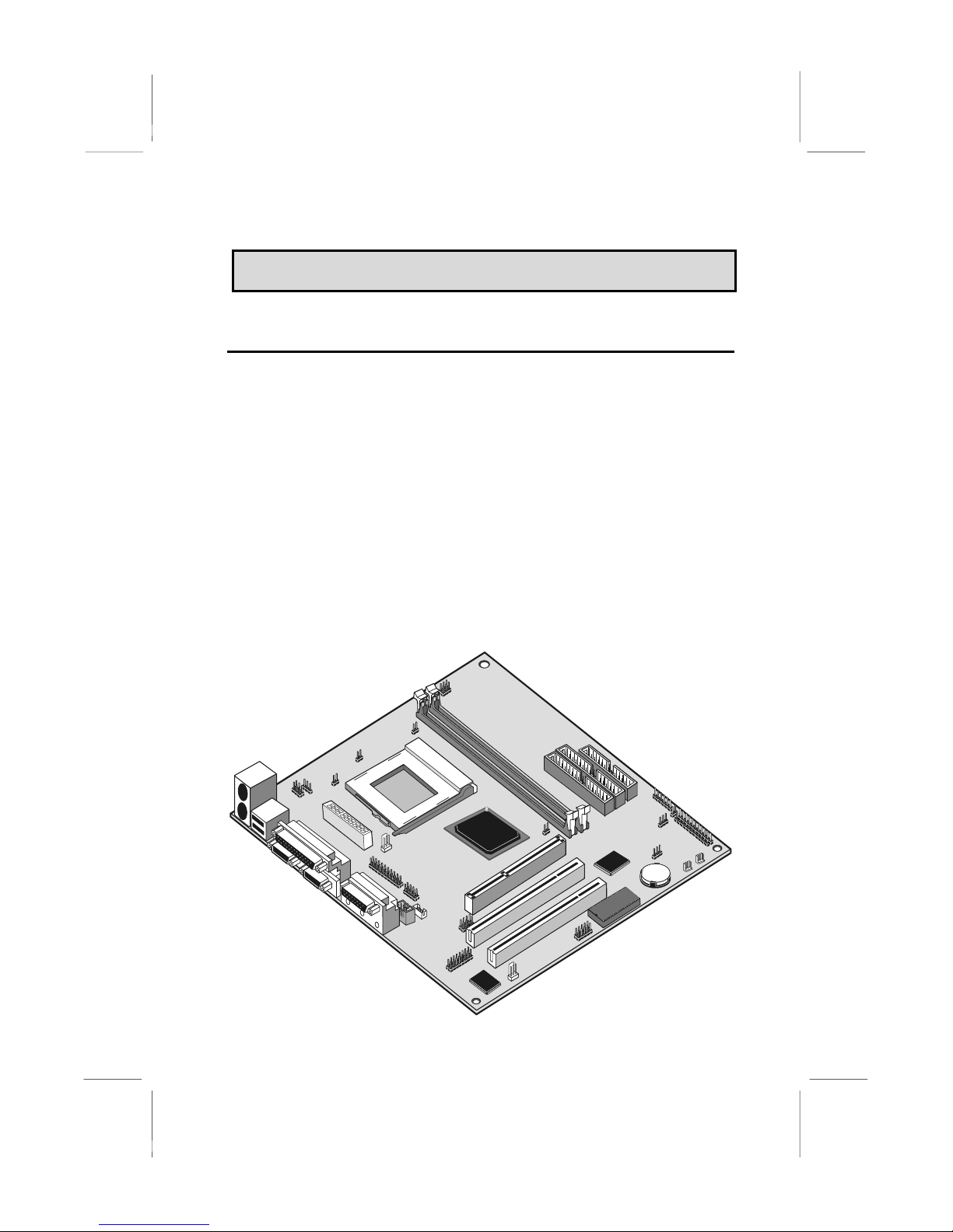
Congratulations on purchasing the KOB 630e CFSFx mainboard.
The KOB 630e CFSFx mainboard is a Flex-ATX mainboard that uses 4layer printed circuit board and measures 228mm x 190mm. The
mainboard has a PPGA (Plastic Pin Grid Array) PGA370 processor
socket. This feature means that you can install the mainboard with a
PPGA Celeron processor.
The KOB 630e CFSFx is installed with the very powerful SIS630 chipset,
which includes integrated built-in video, audio, networking (optional)
and communications capabilities. Two 32-bit PCI expansion slots are
provided, plus a riser card slot for video expansion capabilities. Two
DIMM sockets are available for the installation of up to 1 GB SDRAM
memory. This mainboard is an ideal platform for an inexpensive entry
level or business class multimedia personal computer.
1
Page 2

This chapter contains the following information:
About the Manual explains how the information in this manual is
organized
Checklist comprises a list of the standard and optional components
that are shipped with this mainboard
Recommendations lists some Do’s and Don’ts from the
manufacturer to help ensure reliability and performance from this
product
Features highlights the functions and components that make this
one of the best value mainboards on the market
About the Manual
The manual consists of the following chapters:
Introduction
Use the Introduction Chapter to learn about the features of the
mainboard, and the checklist of items that are shipped with the package.
Installation
Use the Installation Chapter to learn how to install the mainboard and
get your system up and running.
Setup
Use the Setup Chapter to configure the mainboard for optimum
performance.
Software
Use the Software Chapter to learn how to use the software drivers and
support programs that are provided with this mainboard.
2
Page 3

Checklist
Compare the contents of your mainboard package with the standard
checklist below. If any item is missing or appears damaged, please
contact the vendor of your mainboard package.
Standard Items
1 x KOB 630e CFSFx Mainboard
1 x Cable/Bracket Pack
Diskette drive ribbon cable
IDE drive ribbon cable
This User’s Manual
Software Support CD-ROM Disc
Optional items
1 x V.90 Fax/modem Card
1 x SIS301 Riser Card
Recommendations
This mainboard automatically determines the CPU clock frequency and
system bus frequency for the kind of processor that you install. You may
be able to change these automatic settings by changing the settings in
the system setup utility. We strongly recommend that you do not
overclock the mainboard to run processors or other components faster
than their rated speed.
Overclocking components can adversely affect the reliability of the
system and introduce errors into your system. Overclocking can
permanently damage the mainboard by generating excess heat in
components that are run beyond the rated limits.
Components on this mainboard can be damaged by discharges of static
electricity. Handle the board carefully holding it by the edges. Don’t flex
or stress the circuit board. Keep the board in its static-proof packing until
you are ready to install it. Follow the static guidelines given at the
beginning of Chapter 2.
3
Page 4

Features
The key features of this mainboard are the wide range of processors that
can be installed, and the high level of integration, which includes built-in
audio, video, (optional) networking, and communications.
Value-class Processors
As a platform for a value PC, the KOB 630e CFSFX includes a socket370 for the installation of the latest PPGA packaging processors from
Intel.
The new generation PPGA Celeron processors ship in the familiar
square plastic package, and they install in a Zero Insertion Force (ZIF)
socket called a Socket-370. The new Celeron processors are close to
Pentium-II performance because they include a level-2 cache memory of
128K. However, they operate over a 66 MHz system bus and they
currently ship at clock speeds of up to 533 MHz.
Powerful Chipset Support
The processor is supported by the powerful SiS630 chipset. The SiS630
includes a built-in 128-bit AGP graphics accelerator, an integrated 3D
PCI audio controller, and an optionally built-in 10BaseT/100BaseTX
network adapter. The SiS630 controls up to 1 GB of SDRAM memory.
The chipset also supports ACPI Ver.1.0 (Advanced Configuration and
Power Management Interface) and APM (Advanced Power
Management) power management. It provides two PCI IDE channels
with UDMA 33/66, a floppy diskette drive interface, and two busmastering PCI slots. The chipset meets the requirements for the PC99
specification.
Inexpensive Memory
The board has two DIMM sockets for the installation of 168-pin, 3.3V
non-buffered DIMM memory modules. The DIMM memory modules must
be installed with SDRAM memory chips. The KOB 630E CFSFX board
supports a memory bus of 100 MHz. Each installed memory module can
be populated with 16 MB up to 512 MB of memory, so a maximum total
of 1 GB memory can be installed. The integrated video system uses a
shared memory architecture so that you must reserve some of the
installed memory as video memory using the system BIOS. You must
install at least one memory module, with a minimum capacity of 16 MB,
which can be installed in either available DIMM slot.
4
Page 5

Highly Integrated Design
As well as the SIS630 chipset, the KOB 630e CFSFX features other
highly integrated silicon chips. The SIS950 I/O controller handles the
mainboard’s I/O functions, as well as hardware monitoring. The
HT8738/PCI C3DX is a two-chip solution that provides an integrated
audio and fax/modem system.
Built-in AGP 3D-Graphics
The SiS630 chipset includes an integrated 128-bit 2D/3D graphics
accelerator. The graphics system uses the Ultra-AGP architecture and
uses a shared memory scheme that allows up to 64 MB of system
memory to be used as video memory. The graphics system includes
special accelerators for DVD playback and supports screen resolutions
up to 1920 x 1440 and color depths up to 16 M (True Color). Driver
support is provided for Windows 95/98, Windows 2000, Windows NT 4.0,
and OS/2.
Built-in V.90 Fax/modem (DAA Module is optional)
The KOB 630e CFSFX mainboard has a built-in 56 Kbps fax/modem.
That supports the V.90 protocol. The chip is integrated with the built-in
audio system to support voice as well as data transmissions. In order to
use the built-in fax/modem, you must install a DAA module that supplies
the RJ11 sockets for LINE and TELEPHONE.
Expansion Options
The KOB 630e CFSFX mainboard is pre-installed with features such as
audio, video, networking (optional) and a DAA module (optional) for a
modem, that normally requires add-in cards, so the three 32-bit PCI slots
provide plenty of expansion potential. The PCI slots support bus
mastering.
Integrated I/O
The mainboard has a full set of I/O ports and connectors. The I/O
template on the backplane includes two PS/2 ports for mouse and
keyboard, one serial port, one parallel port, one VGA monitor port, one
game/MIDI port, two USB ports and audio jacks for microphone, line-in
and line-out. The board has a header for the optional installation of an IR
port, a second serial port, and 24-bit digital audio. The board includes
two PCI IDE channels with UltraDMA 33/66 support, and a floppy disk
drive interface.
Hardware Monitoring
Hardware monitoring is fully supported and the board ships with
hardware monitoring software. System assemblers and network
5
Page 6

administrators can reduce downtime and repair costs by monitoring
critical temperatures and voltages on the system. The supplied hardware
monitoring software lets you set parameters that prompt warnings when
they are exceeded.
Keyboard Power On Feature
Using the system BIOS setup program, you can configure the system to
turn on by using a keyboard typed password or by pressing a hot-key
combination (Ctrl+Alt+Backspace). A green keyboard is not required.
Programmable Firmware
The mainboard includes Award BIOS that allows BIOS setting of CPU
parameters. The fully programmable firmware enhances the system
features and allows users to set power management, CPU and memory
timing, LAN and modem wake-up alarms, and so on. The firmware can
also be used to set parameters for different Celeron processor clock
speeds so that you don’t need to change mainboard jumpers and
switches.
6
Page 7

CChhaapptteerr 22:: IInnssttaallllaattiioonn
Quick Installation Table
This chapter explains how to successfully install the mainboard into a
computer case and build a working system. The installation procedure is
as follows:
Quick Jumper
Setting Reference
Before you Begin
Preparing the
Mainboard
Install Other
Hardware
Make the External
Connections
Provides a quick reference for the jumper
settings on this mainboard.
Provides advice on choosing a case,
avoiding static electricity damage, and setting
jumpers.
Provides a guide to the mainboard and I/O
port locations, full details on the jumper
settings, and advice on installing the
mainboard in the system case.
Provides guidance on installing essential
hardware: processor, memory, hard disk
drive, CD-ROM, floppy disk drive, and
expansion cards.
Provides advice on using the external I/O
ports to install peripheral devices such as a
keyboard, a monitor, a mouse, a printer,
loudspeakers, and so on.
7
Page 8
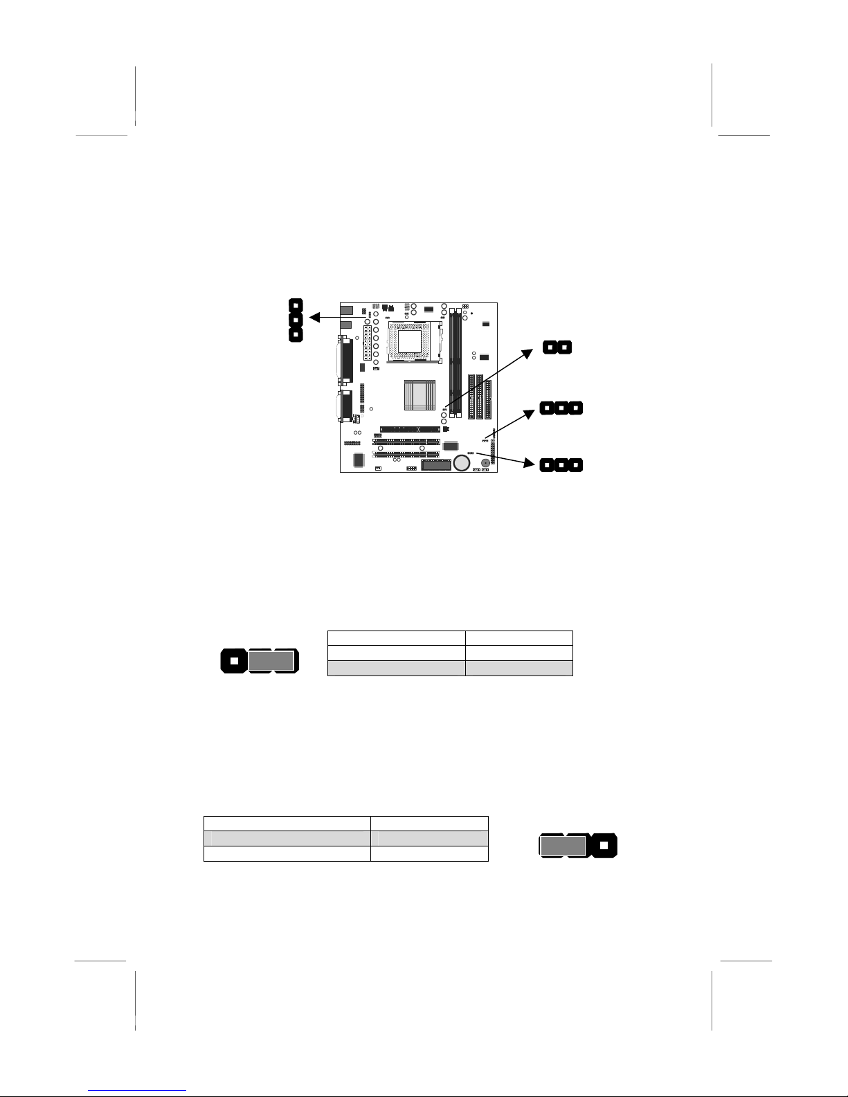
Quick Jumper Setting Reference
If you are familiar with most of the material in this chapter, you can begin
preparing the mainboard for installation by using this quick reference to
begin the setting the jumpers. A detailed description of the jumper setting
appears later in this chapter.
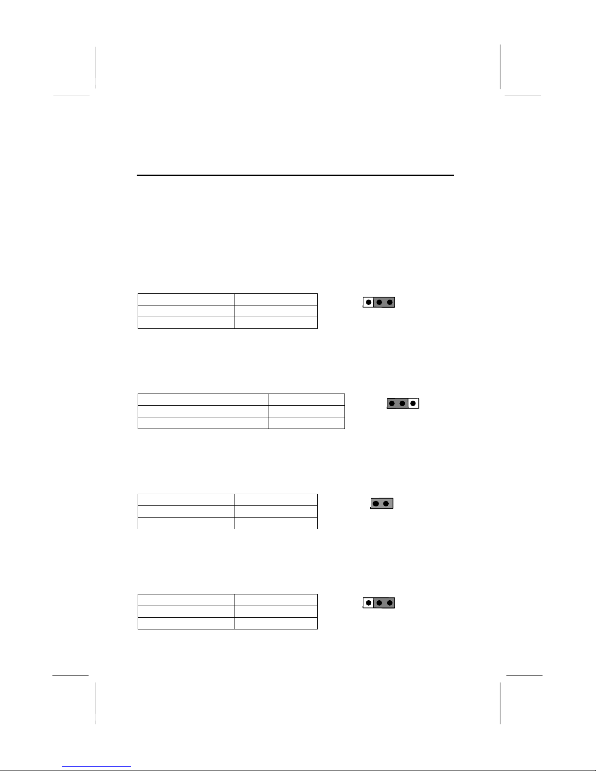
JP1: Clear CMOS memory jumper
Use this 3-pin jumper to clear all the current data stored in the CMOS
memory.
Function Jumper Cap
Clear CMOS Short pins 1-2
Normal operation Short pins 2-3
JP2: Keyboard power on jumper
Use this 3-pin jumper to enable keyboard power on with hot keys or
password.
Function Jumper Cap
Enable keyboard power on Short pins 1-2
Disable keyboard power on Short pins 2-3
JP1
1 2 3
JP2
1 2 3
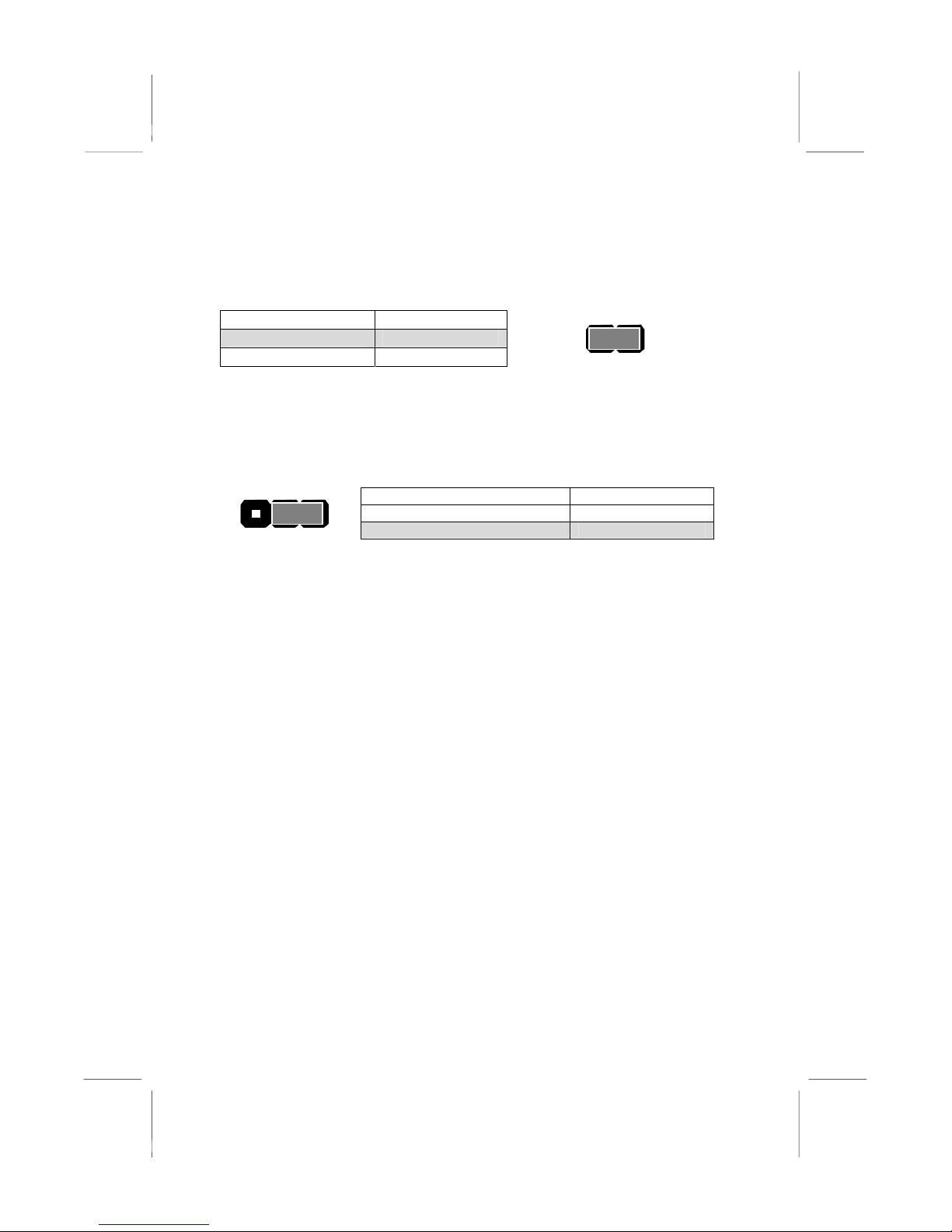
JP7: PAL/NTSC selection jumper
Use this 2-pin jumper to set the video output from the optional TV/LCD
card to either PAL or NTSC
Function Jumper Cap
Enable PAL Short pins 1-2
JP7
1 2
Enable NTSC Open pins 1-2
JP9: Flash BIOS jumper
Use this 3-pin jumper to allow the BIOS CMOS memory to be flashed,
i.e. a new BIOS version to written to the CMOS chip onboard.
Function Jumper Cap
Enable Flash BIOS Short pins 1-2
JP9
1 2 3
Normal operation Short pins 2-3
8
Page 9

Note: JP3, JP4, JP5 and JP8 are featured on the board but are
currently not supported.
PANEL1: Panel connectors for switches and indicators
Use the panel connector to implement the switches and indicators on
your system case.
Function Pins
Speaker +1, 3, 5, 7
Power Indicator +2, +4, 6
Keylock 8, 10
Green Indicator 13, 14
Hard Disk Indicator
Reset Switch
Suspend Switch 19, 20
Power Switch 21, 22
+15, 16
17, 18
KeyLock
Power LED
22 21
Power SW
Suspend SW
Reset SW
HDD LED
Green LED
Speaker
2 1
PANEL1
9
Page 10

Before You Begin
Before you begin to install your KOB 630e CFSFx mainboard, take some
precautions to ensure that you avoid the possibility of damage to the
product from static electricity. Ensure too that you are installing the
mainboard into a suitable case.
Static Electricity
In adverse conditions, static electricity can accumulate and discharge
through the integrated circuits and silicon chips on this product. These
circuits and chips are sensitive and can be permanently damaged by
static discharge.
♦ If possible wear a grounding wrist strap clipped to a safely
grounded device during the installation.
♦ If you don’t have a wrist strap, discharge any static by touching
the metal case of a safely grounded device before beginning the
installation.
♦ Leave all components inside their static-proof bags until they are
required for the installation procedure.
♦ Handle all circuit boards and electronic components carefully.
Hold boards by the edges only. Do not flex or stress circuit
boards.
Choosing a Case
The mainboard complies with the specifications for the FlexATX system
case, although it can also be installed in most micro-ATX case designs.
The micro-ATX specifications include a maximum size of 9.0” x 7.5”
(228mm x 190mm), a reduced number of expansion slots, and support
for a smaller power supply unit.
Some features on the mainboard are implemented by cabling connectors
on the mainboard to indicators and switches on the system case. Ensure
that your case supports all the features required. The KOB 630e CFSFx
mainboard can support one or two floppy diskette drives, and four
enhanced IDE drives. Ensure that your case has sufficient power and
space for all the drives that you intend to install.
10
Page 11

The mainboard has a set of I/O ports on the rear edge. Ensure that your
case has an I/O template that supports the I/O ports and expansion
slots.
How to Set Jumpers
A jumper consists of two or more pins mounted on the mainboard. Some
jumpers might be arranged in a series with each pair of pins numbered
differently. Jumpers are used to change the electronic circuits on the
mainboard. When a jumper cap is placed on two jumper pins, the pins
are SHORT. If the jumper cap is removed (or placed on just a single pin)
the pins are OPEN.
This illustration shows a 2-pin jumper. When the
OPEN
SHORT
This illustration shows a 3-pin jumper. The jumper cap is
placed on pins 2 and 3, so this jumper setting is SHORT
PINS 2-3.
jumper cap is placed on both pins, the jumper is
SHORT. If you remove the jumper cap, or place the
jumper cap on just one pin, the jumper is OPEN.
This illustration shows the same 3-pin jumper. The jumper
cap is placed on pins 1 and 2, so this jumper setting is
SHORT PINS 1-2.
In this manual, all the jumper illustrations clearly show the pin numbers.
When you are setting the jumpers, make sure that the jumper caps are
placed on the correct pins to select the function or feature that you want
to enable or disable.
11
Page 12
A
Preparing the Mainboard
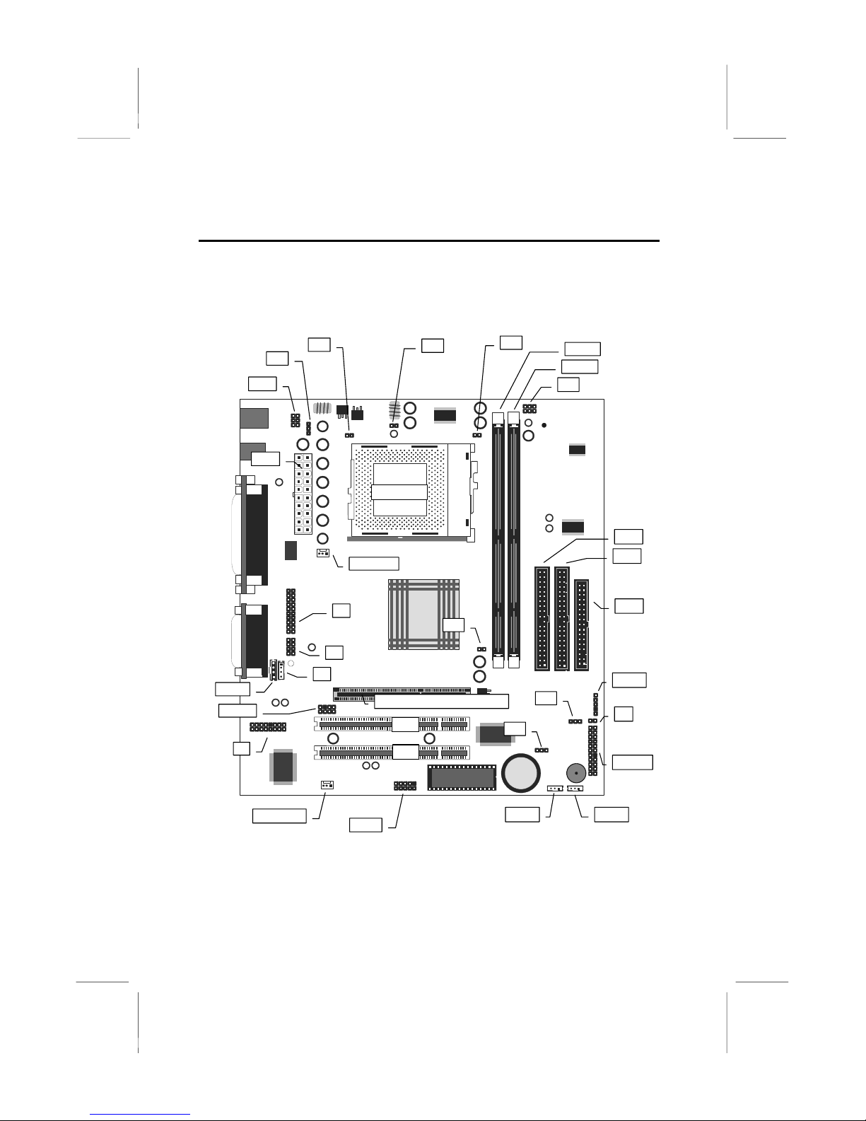
Mainboard Guide
Use the following illustration and key to identify the components on your
mainboard.
JP6
DIMM1
DIMM2
JP8
IDE1
IDE2
JHD1
TX1
JP2
JP5
JP3
Socket-370
CPUFAN1
CD-IN
SPDIF1
J4
CASFAN1
J1
JP7
J6
J3
TV-Out/LCD Panel Riser Slot
PCI1
PCI2
COM2
JP1
JP9
WOM1
FDD1
SIR1
J5
PANEL1
WOl1
12
Page 13

Key to Mainboard Components
Component
Description
Socket-370 Socket for PPGA Celeron Processors
PCI 1, 2
TV-Out/LCD
Two 32-bit PCI Slots
Slot for a TV-Out/LCD Panel Riser card.
Panel Riser
DIMM 1, 2 Two slots for 168-pin SDRAM memory module
FDD1 Connector for floppy disk drives
IDE1, IDE2 Primary and secondary IDE channels
ATX1 Connector for ATX power supply
SIR1 Connector for optional infrared port
PANEL1
Panel connector for switches and indicators
WOM1 Connector for modem wake up
WOL1 Connector for LAN wake up
SPDIF1 SPDIF In/out connector (24-bit digital audio
interface)
*LED2 DIMM Power LED
COM2 Connector for serial port 2/4
CASFAN1 Power connector for case cooling fan
CPUFAN1 Power connector for CPU cooling fan
CD-IN Audio connector for CD-ROM/DVD drive
JHD1 Auxiliary keyboard connector
JP1 Clear CMOS jumper
Keyboard power on jumper
JP2
JP3, JP4, JP5,
and JP8
These jumpers are featured, but currently not
supported
JP7
Select PAL/NTSC output for optional TV/LCD card
JP9
Flash BIOS jumper
J1 Header for digital I/O port on front panel (optional)
J3 Auxiliary audio connector for CD-ROM/DVD drive
J4 Connector for modem DAA module
J5 Connector for two-color LED
J6 Header for analog I/O port on front panel (optional)
*LED2
This red indicator turns on whenever the system enters Suspend-to-RAM
mode.
13
Page 14
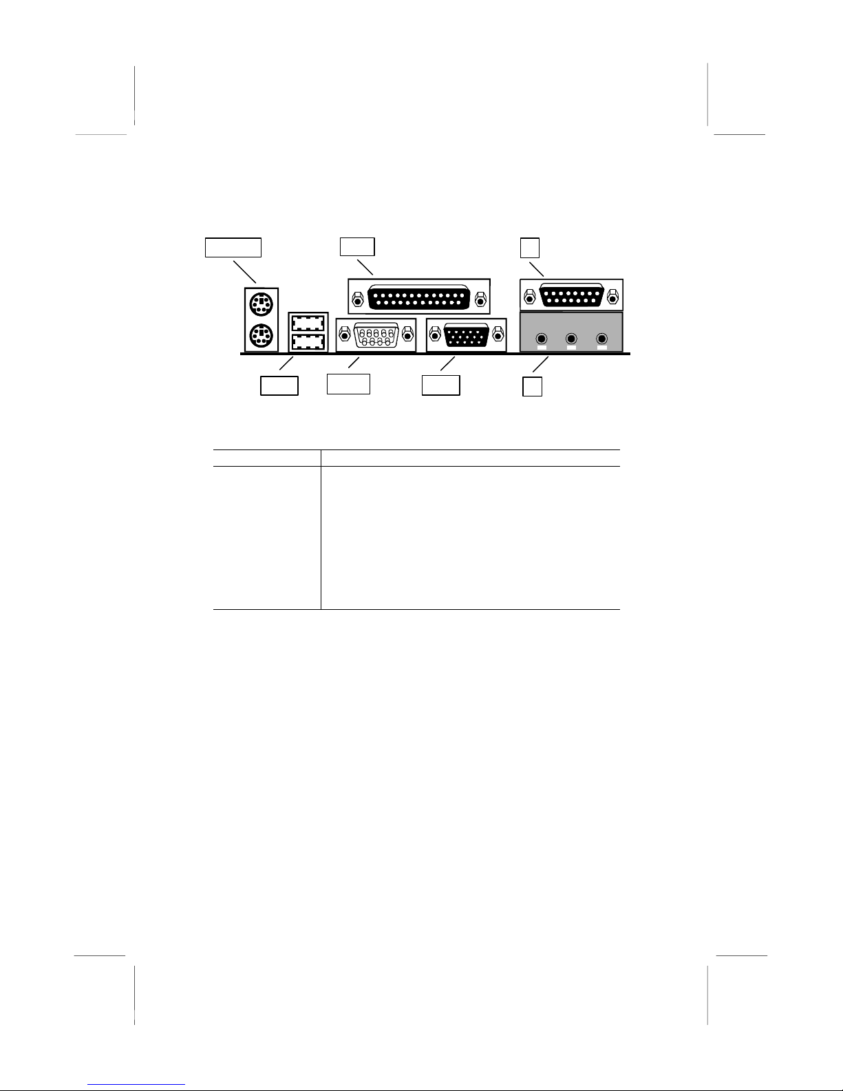
I/O Ports Side View
PS2KBM
USB1
Key to I/O Ports
Component Description
PS2KBM PS/2 port for pointing device (upper port)
JS (Upper) External game/MIDI port
JS (Lower) Audio jacks for (from left to right) line out, line
JSLPT1
COM1
VGA1
JS
PS/2 port for keyboard (lower port)
LPT1 External parallel port
in, microphone
VGA1 External monitor port
COM1 External serial port COM1/3
USB1 Two stacked Universal Serial Bus ports
14
Page 15
Check the Jumper Settings
Check all the mainboard jumpers to ensure that the board is configured
correctly.
JP2
JP7
JP1
JP9
JP1 Clear CMOS Memory Jumper
This jumper lets you erase the system setup settings that are stored in
CMOS memory. You might need to erase this data if incorrect settings
are preventing your system from operating. To clear the CMOS memory,
turn off the system, disconnect the power cable from the mainboard, and
short the appropriate pins for a few seconds.
JP1
1 2 3
Function Jumper Cap
Clear CMOS Short pins 1-2
Normal Operation Short pins 2-3
JP2: Keyboard Power On Jumper
This jumper lets you use a typed-in password as a power switch to turn
your system on. If you enable this property, you need to define the
password or the hot keys using the setup utility. See Chapter 3.
Function Jumper Cap
Enable keyboard power on Short pins 1-2
Disable keyboard power on Short pins 2-3
JP2
1 2 3
15
Page 16
JP7: PAL/NTSC selection jumper
Use this 2-pin jumper to set the video output from the optional TV/LCD
card to either PAL or NTSC
JP7
Function Jumper Cap
Enable PAL Short pins 1-2
Enable NTSC Open pins 1-2
1 2
JP9: Flash BIOS Jumper
Use this 3-pin jumper to allow the BIOS CMOS memory to be flashed,
i.e. a new BIOS version to written to the CMOS chip onboard.
JP9
1 2 3
Function Jumper Cap
Enable Flash BIOS Short pins 1-2
Normal operation Short pins 2-3
16
Page 17
Install the Mainboard in the Case
The mainboard is drilled with a series of holes. Most system cases have
mounting brackets installed in the case which correspond to the holes in
the mainboard. You can secure the mainboard in the system case by
placing the mainboard over the mounting brackets and driving screws
through the mainboard into the mounting brackets.
Most cases have a choice of I/O templates in the rear panel. Make sure
that the I/O template in the case matches the I/O ports installed on the
rear edge of the mainboard.
Note: Do not overtighten the screws as this can stress the
mainboard.
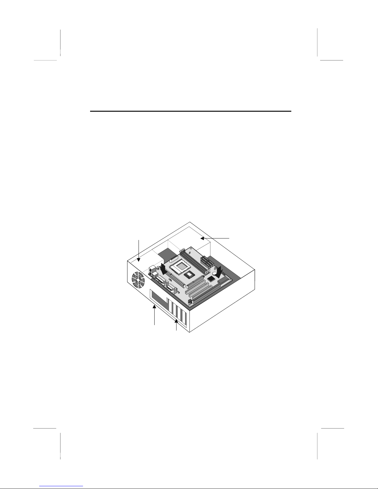
The illustration below shows a mainboard installing in a standard
desktop case.
Power Supply
Unit
Drive
Cage
I/O
Template
Expansion
Slots
17
Page 18
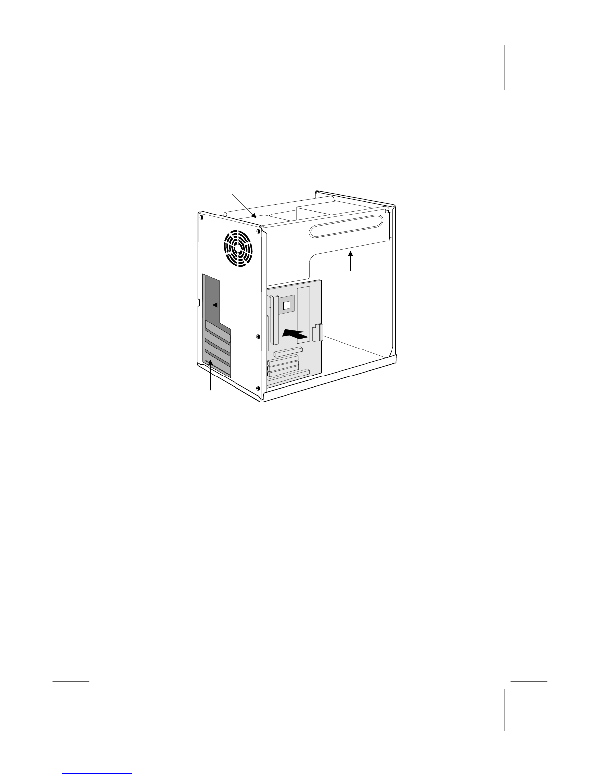
The illustration below shows the mainboard installing into a tower-type
case.
Power Supply
Unit
Drive
Cage
I/O
Template
Expansion
Slots
18
Page 19
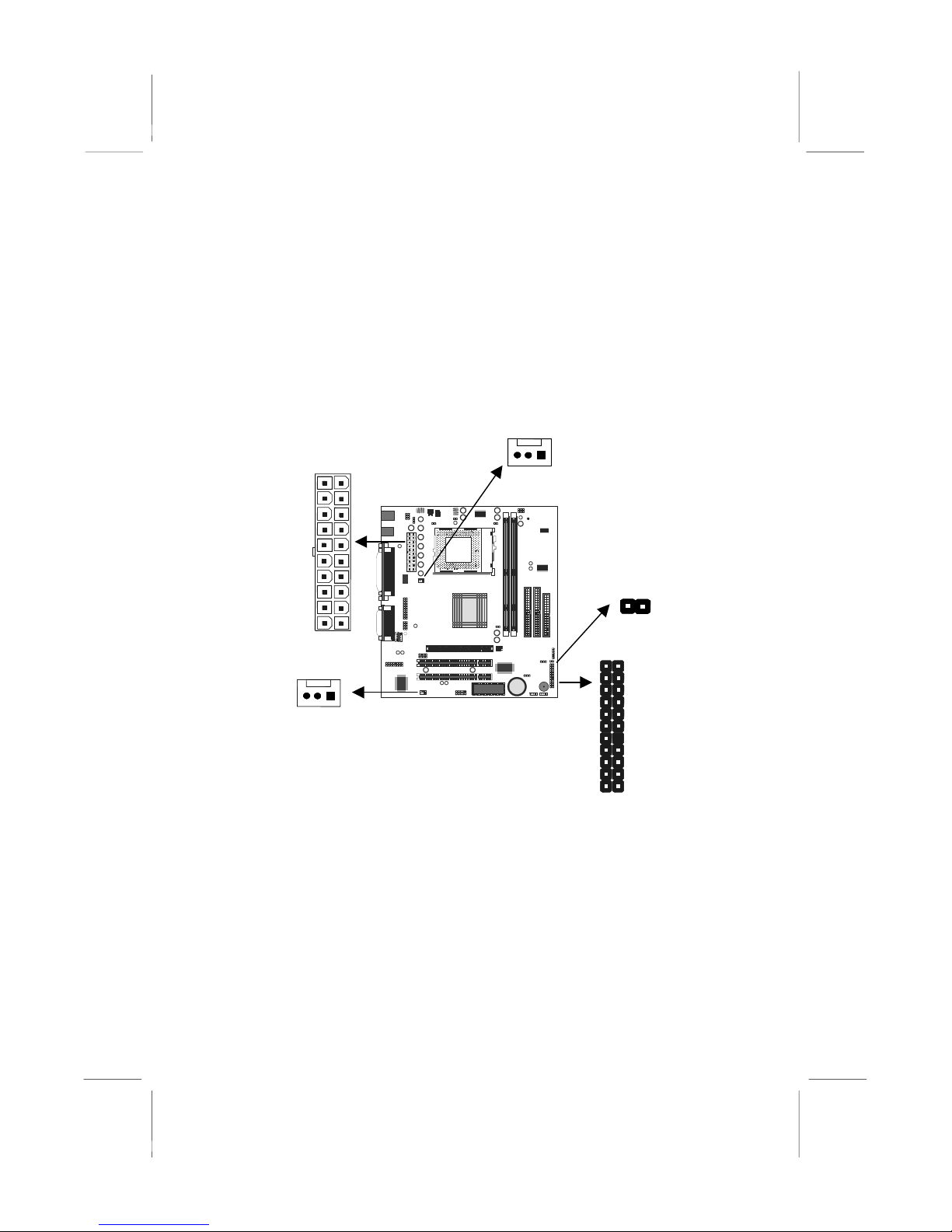
Connecting Power, Chassis Fans, and Switches and
Indicators
After you have installed the mainboard into the system case, connect the
power cable from the case power supply unit to the mainboard power
connector ATX1. Connect the chassis/CPU fans (if your case has them)
to the 12V power supply connectors CASFAN1or CPUFAN1 on the
mainboard. Then connect the case switches and indicators to the
PANEL connector and the J5 LED connector on the mainboard.
CPUFAN1
ATX1
J5
CASFAN1
PANEL1
Power Connector
Locate the power cable from the case power supply unit and plug it into
the ATX1 power connector.
Chassis and CPU Fans
If your case has a cooling fan installed in the chassis, plug the cable
from the chassis-mounted fan into the mainboard 12V power supply
connector CASFAN1. If your CPU has a cooling fan, plug the cable into
the 12V power supply connector CPUFAN1.
19
Page 20

Green LED Connector
If your case has a dual color indicator lamp for the ACPI Green suspend
mode, connect the cable from the indicator to the J5 dual color LED
connector.
Panel Connector
The mainboard PANEL connector has a standard set of switch and
indicator connectors that are commonly found on ATX system cases.
Use the illustration below to make the correct connections to the case
switches and indicators.
Function Pins
Speaker +1, 3, 5, 7
Power Indicator +2, +4, 6
Keylock 8, 10
Green Indicator 13, 14
Hard Disk Indicator +15, 16
Reset Switch 17, 18
Suspend Switch 19, 20
Power Switch 21, 22
PANEL1
SMI Button 19-20
HDD LED 15-16
22 21
Power SW 21-22
Reset SW 17-18
KeyLock 8-10
Power LED 2-4-6
Speaker 1-3-5-7
2 1
20
Page 21

Install Other Hardware
Start installing the essential hardware required to get your system
started.
Install the Processor
This mainboard has a Socket-370 processor socket. To choose a
processor, you need to consider the performance requirements of the
system and also the price of the processor. Performance is based on the
processor design, the clock speed and system bus frequency of the
processor, and the quantity of internal cache memory and external cache
memory. Higher clock speeds and larger amounts of cache memory
deliver greater performance.
About Socket-370 Processors
The socket-370 on this board currently supports PPGA Intel Celeron
processors.
Intel PPGA Celeron
PPGA stands for Plastic Pin Grid Array. This is a description of the
square plastic package that the processor is embedded in. The PPGA
Celeron is identical to the SEPP Celeron, except for the external
packaging. PPGA Celerons run at clock speeds from 300 MHz through
to 533 MHz. All the current PPGA Celerons operate over a 66 MHz
system bus. The PPGA Celeron is less expensive than a SEPP Celeron
with the same clock speed.
New Processors
This board is designed to support some future processors that have not
yet been released. Ask your mainboard vendor for an up-to-date list of
processors that can be installed on this mainboard.
21
Page 22

Installing a Socket-370 Processor
To install the mainboard with a PPGA Celeron processor, follow the
steps below.
Locate the Socket-370 and CPUFAN1
Socket-370
Pin-1 corner
CPUFAN1
Locking lever
1. On the mainboard, locate the socket-370 and CPUFAN1.
2. On the socket-370, pull the locking lever away from the socket to
unhook it and then raise the locking lever to the upright position.
3. Identify the pin-1 corner on the socket-370 and the pin-1 corner on
the processor. The socket pin-1 corner is adjacent to the handle of
the locking lever. The processor pin-1 corner is beveled.
4. Matching the pin-1 corners, drop the processor into the socket. No
force is required and the processor should seat into the socket
easily.
5. Swing the locking lever down and hook it under the latch on the
edge of the socket. This locks the processor in place.
6. Locate the power cable on the heatsink/cooling fan assembly that is
attached to the top of the processor.
7. Plug the power cable into the CPUFAN1 12V power supply on the
mainboard.
22
Page 23

Cooling fan
power cable
CPUFAN1 cooling
fan power supply
Socket-370 processor
with heatsink/cooling
fan assembly
Socket-370 with
locking lever in
upright position
The mainboard must be configured to deliver the correct clock speed
and the correct system bus for the kind of processor that you have
installed. You can do this by using the system setup utility. The first time
you start the system, immediately enter the setup system and make the
appropriate settings. Usually, you can automatically configure the CPU
by using the CPU & BIOS Features page of the setup utility. See
Chapter 3 for more information.
23
Page 24

Install the Memory Modules
For this mainboard, you must use 168-pin 3.3V non-buffered Dual In-line
Memory Modules (DIMMs). The memory chips must be standard or
registered SDRAM (Synchronous Dynamic Random Access Memory).
The memory bus can run at 66 MHz or 100 MHz (100 MHz is
recommended). If your processor operates over a 100 MHz system bus,
you must install PC-100 memory that also operates over a 100 MHz bus.
If you install a processor that operates over a 66 MHz bus, you can
install memory chips that operate at 66 MHz.
You must install at least one memory module. You can install the module
in any one of the three DIMM slots. Each module may be installed with
up to 512 MB of memory so the maximum capacity is 1 GB. The
mainboard supports memory chips that have EC (Error Correction) or
ECC (Error Correction Code).
1. Locate the DIMM slots on the mainboard.
Locking latches
DIMM1
DIMM2
Memory module
2. The DIMM slots are keyed with notches and the DIMMs are keyed
with cut-outs so that they can only be installed correctly. Check that
the cut-outs on the DIMM module edge connector match the notches
in the DIMM slot.
3. Push the latches on each side of the DIMM slot down.
24
Page 25

4. Install the DIMM module into the slot and press it carefully but firmly
down so that it seats correctly. The latches at either side of the slot
will be levered upwards and latch on to the edges of the DIMM when
it is installed correctly.
Install a Hard Disk Drive and CD-ROM
This section describes how to install IDE devices such as a hard disk
drive and a CD-ROM drive.
Note: Ribbon cable connectors are usually keyed so that they can
only be installed correctly on the device connector. If the
connector is not keyed make sure that you match the pin-1 side of
the cable connector with the pin-1 side of the device connector.
Each connector has the pin-1 side clearly marked. The pin-1 side
of each ribbon cable is always marked with a colored stripe on the
cable.
About IDE Devices.
Your mainboard has a primary IDE channel interface (IDE1) and a
secondary IDE interface (IDE2). The mainboard ships with one IDE
ribbon cable which supports one or two IDE devices. All IDE devices
have jumpers or switches that can be used to set the IDE device as
MASTER or SLAVE.
If you install two IDE devices on one cable, you must make sure that one
device is set to MASTER and the other device is set to SLAVE. The
documentation of your IDE device explains how to do this.
If you want to install more than two IDE devices, obtain a second IDE
cable and you can add two more devices to the secondary IDE channel.
If there are two devices on the cable, make one MASTER and one
SLAVE.
About UDMA
This board supports UltraDMA 33/66. UDMA is a technology that speeds
the performance of devices in the IDE channel. We recommend that you
install IDE devices that support UDMA, and use IDE cables that support
UDMA.
25
Page 26

Installing a Hard Disk Drive
1. Install the hard disk drive into the drive cage in your system case.
2. Plug the IDE cable into the primary IDE channel on the mainboard
IDE1.
3. Plug one of the connectors on the IDE cable into the IDE connector
on the back edge of the hard disk drive. It doesn’t matter which
connector on the cable that you use. Make sure that you have the
pin-1 side of the cable matched with the pin-1 side of the connector.
4. Plug a power cable from the case power supply unit into the power
connector on the back edge of the hard disk drive.
5. When you first start up your system, go immediately to the setup
utility and use the IDE Hard Disk Auto Detect feature to configure the
IDE devices that you have installed. See Chapter 3 for more
information.
IDE connector
IDE ribbon cable
IDE2
Hard disk drive
Power connector
IDE1
Installing a CD-ROM/DVD Drive
1. Install the CD-ROM/DVD drive into the drive cage in your system
case. Plug the IDE cable into the primary IDE channel on the
mainboard IDE1.
2. Plug one of the connectors on the IDE cable into the IDE connector
on the back edge of the CD-ROM/DVD drive. It doesn’t matter which
connector on the cable that you use. Make sure that you have the
pin-1 side of the cable matched with the pin-1 side of the connector.
26
Page 27

A
r
3. Plug a power cable from the case power supply unit into the power
connector on the back edge of the CD-ROM/DVD drive.
4. Use the audio cable provided with the CD-ROM/DVD drive to
connect the audio connector on the rear edge of the CD-ROM/DVD
drive to the one of the two audio-in connectors CD-IN and J4 on the
mainboard.
5. When you first start up your system, go immediately to the setup
utility and use the IDE Hard Disk Auto Detect feature to configure the
IDE devices that you have installed. See Chapter 3 for more
information.
Power connector
IDE connector
udio connecto
CD-ROM/DVD drive
IDE ribbon cable
IDE2
Hard disk drive
IDE1
CD-IN & J3
Installing a Floppy Diskette Drive
The mainboard has a floppy diskette drive interface and it ships with a
diskette drive ribbon cable that supports one or two floppy diskette
drives. You can install a 5.25” drive or a 3.5” drive with various
capacities. The floppy diskette drive cable has one type of connector for
a 5.25” drive and another type of connector for a 5.25” drive
27
Page 28

1. Install the floppy diskette drive into the drive cage in your system
case. Plug the diskette drive cable into the diskette drive interface on
the mainboard FDD1.
2. Plug one of the connectors on the diskette drive cable into the data
connector on the back edge of the floppy diskette drive. Make sure
that you have the pin-1 side of the cable matched with the pin-1 side
of the connector.
3. Plug a power cable from the case power supply unit into the power
connector on the back edge of the diskette drive.
4. When you first start up your system, go immediately to the setup
utility and use the Standard page to configure the floppy diskette
drives that you have installed. See Chapter 3 for more information.
Data connector
Floppy diskette
drive cable
Power
connector
Floppy diskette
drive
FDD1
28
Page 29

Using the Expansion Slots
This mainboard has two 32-bit PCI expansion slots and one TV-Out/LCD
Panel Riser slot.
PCI Slots: The PCI slots can be used to install add-in cards that have
the 32-bit PCI (Peripheral Components Interconnect) interface.
TV-Out/LCD Panel Riser: The TV-Out/LCD Panel Riser slot allows for
the installation of a riser card for exporting the system’s video output to
an TV receiver or an external LCD panel.
PCI1
TV-Out/
LCD
Panel
Riser
PCI2
1. Before installing an expansion card, check the documentation for the
card carefully. If the card is not Plug and Play, you may have to
manually configure the card before installation.
2. Select which expansion slot you are going to use for your add-in
card.
3. In the system case, remove the blanking plate from the slot in the
system case that corresponds to the expansion slot that you are
going to use.
4. Position the edge connector of the add-in card over the expansion
slot. Position the metal bracket of the card in the empty slot in the
system case.
5. Install the edge connector of the add-in card into the expansion slot.
Press down quite firmly so that you are sure that the edge connector
is correctly seated in the slot.
29
Page 30

6. Secure the metal bracket of the card in the empty slot in the system
case with a screw.
7. For some add-in cards, for example graphics adapters and network
adapters, you have to install drivers and software before you can
begin using the add-in card.
PCI add-in card
Metal bracket
Edge connector
PCI slot
Add-in Card Options
The mainboard has two features that can be used if you have installed
either a fax/modem card or a network adapter card.
WOL1: Wake on LAN
If you have installed a network adapter (LAN adapter), you can use the
cable provided with the card to plug into the WOL1 connector on the
mainboard. This is the Wake On LAN feature. When your system is in a
power–saving mode, any traffic through the network automatically
resume the system. You must enable this item using the Power
Management page of the setup utility. See Chapter three for more
information.
30
Page 31

WOM1: Wake on Modem
If you have installed a fax/modem card, you can use the cable provided
with the card to plug into the WOM1 connector on the mainboard. This is
the Wake On Modem feature. When your system is in a power–saving
mode, any incoming calls to the modem automatically resume the
system. You must enable this item using the Power Management page
of the setup utility. See Chapter three for more information.
WOM1
WOL1
Install Options and Extension Brackets
This mainboard has a number of special connectors that allow you to
add optional features to your system. You can install any of the following
items:
♦ Fax/modem card option
♦ Infrared port
♦ Second serial port
♦ 24-bit digital audio extension bracket (SPDIF)
♦ Digital I/O port on front panel
♦ Analog I/O port on front panel
Fax/modem Card
You must install the fax/modem card in order to use the built-in
fax/modem.
The fax/modem card is an optional item supplied with this mainboard.
31
Page 32

1. Locate the J4 fax/modem connector on the mainboard.
J4
2. Remove the expansion slot blanking plate from the system chassis
that is adjacent to the fax/modem connector.
3. Install the fax/modem card on to the J4 connector as shown below.
The RJ11 Line and Telephone sockets on the bracket are positioned
in the expansion slot with the removed blanking plate.
Line and Tel
RJ11 sockets
J4
fax/modem
connector
Fax/modem
card
32
Page 33

Infrared Port
This option can be purchased from third-party vendors.
SIR1
1. If you are installing an optional serial infrared port, connect the cable
from the optional IR port to the SIR1 connector on the mainboard.
2. After you have connected the cable, secure the optional IR port to
the appropriate place on your system case.
Note: An IR port may use some of the resources required by a
second serial port or a fax/modem card. If you have more than
one of these items installed, you may not be able to use them at
the same time. You can use the Peripherals page of the setup
utility to switch resources between an IR port and a second serial
port. See Chapter 3 for more information.
33
Page 34

Second Serial Port
The mainboard has a connector for an optional second serial port. You
can implement the second serial port by connecting an extension bracket
with a serial port to the onboard serial port connector COM2.
COM2
Note: An second serial port may use some of the resources
required by an infrared port or a fax/modem card. If you have
more than one of these items installed, you may not be able to
use them at the same time. You can use the Peripherals page of
the setup utility to switch resources between an IR port and a
second serial port. See Chapter 3 for more information.
Digital Audio Extension Bracket
You can purchase an optional 24-bit digital audio extension bracket from
a third-party vendor. You can use the audio RCA jacks to connect to
digital audio devices. If your CD-ROM/DVD drive has digital audio
output, you can connect it to the input pins of the SPDIF connector.
On the mainboard, locate the digital audio connector SPDIF1. Connect
the cable from the digital audio extension bracket to SPDIF1. If you have
digital audio output from your CD-ROM/DVD drive, connect it to the
marked audio input pins.
Audio Input
Pins
SPDIF1
34
Page 35

Auxiliary Keyboard Connector
The mainboard has connectors for an additional keyboard port. If your
chassis has an additional bracket on the front side, you can use this
connector on the mainboard to connect the proper feature to the
extension bracket in the case.
JHD1
Digital and Analog I/O port
The mainboard had two connectors/jumpers for support of optional
digital (J1) and analog (J6) I/O ports on the front panel of the system.
In order to enable these ports, short the jumpers as indicated in the table
below.
Enable Digital I/O Port – J1 Short pins:11-12, 13-14, 17-
18, and 19-20
Enable Digital I/O Port – J6 Short pins 3-4, 5-6, and 7-8.
19 20
J1
12
78
J6
12
35
Page 36

Make the External Connections
After you have installed the mainboard, make the connections to the
external ports.
PS2KBM
JSLPT1
USB1
COM1
VGA1
JS
1. PS2KBM is a stack of two PS/2 mini-DIN ports. The upper port can
be used by a PS/2 mouse or pointing device. The lower port can be
used by a PS/2 keyboard.
2. LPT1 is a parallel port that can be used by printers or other parallel
communications devices. The system identifies the parallel port as
LPT1.
3. The upper 15-pin port J2 is a game/MIDI port. You can use this port
to connect a joystick or a MIDI device to your system
4. The lower part of J2 is three audio jacks. The left side jack is for a
stereo line out signal. The middle jack is for a stereo line in signal.
The right side jack is for a microphone.
5. VGA1 is the connector for a display monitor. Plug the data cable
from the monitor into VGA1.
6. COM1 is a serial port that can be used by serial devices such as a
mouse, a fax/modem and so on. This serial port is identified by the
system as COM1/3.
7. USB1 is a stack of two Universal Serial Bus ports. Use these ports to
connect to USB devices.
36
Page 37

External Connector Color Coding
To help identify the external connectors, many connectors now use
standard colors as shown in the table below.
Connector
Analog VGA
Audio line in Light blue
Audio line out Lime
Digital monitor / flat panel White
IEEE 1394 Grey
Microphone Pink
MIDI/Game Gold
Parallel Burgundy
PS/2 compatible keyboard Purple
PS/2 compatible mouse Green
Serial Teal or Turquoise
Speaker out / subwoofer Orange
Right-to-left speaker Brown
USB Black
Video out Yellow
SCSI, network, telephone, modem, and so on None
Color
Blue
37
Page 38

CChhaapptteerr 33:: SSeettuupp
About the Setup Utility
This chapter explains how to use and modify the BIOS setup utility that is
stored on the mainboard. The setup utility stores data about the
mainboard components and the configuration of devices that are
connected to it. This information is used to test and initialize components
at start-up time and to make sure everything runs properly when the
system is operating.
The setup utility is installed with a set of default values. You will probably
have to make changes to the setup utility whenever you add new
components to your system such as new disk drives. You may be able to
generate increased performance by changing some of the timing values
in the setup, but this can be limited by the kind of hardware you are
using, for example the rating of your memory chips. In certain
circumstances, the system may generate an error message that asks
you to make changes to the setup utility. This happens when the system
finds an error during the POST (Power On Self Test) that it carries out at
start up.
Starting the Setup Utility
You can only start the setup utility shortly after the computer has been
turned on. A prompt appears on the computer display which says “Press
DEL to run Setup”. When you see this prompt, press the Delete key, and
the system will start the setup utility and display the main menu of the
utility.
Using the Setup Utility
When you start setup, the main menu appears. The main menu of the
setup utility shows a list of the options that are available. A highlight
shows which option is currently selected. You can use the cursor arrow
keys to move the highlight to other options. When an option is
highlighted, you can execute the option by pressing the Enter key.
Some options lead to dialog boxes which ask you verify that that you
wish to execute that option. You usually answer these dialogs by typing
Y for yes and N for no. Some options lead to dialog boxes which ask for
more information. Setting passwords have this kind of dialog box.
38
Page 39

Some options (marked with a triangle) lead to tables of items that usually
have a value on the right side. The value of the first item is highlighted,
and you can use the cursor arrow keys to select any of the other values
in the table of items. When an item is highlighted, you can change the
value by pressing the PageUp or PageDown keys, or the Plus or Minus
keys. The PageUp and Plus keys cycle forward through the available
values, the PageDown and Minus keys cycle backwards through the
values.
When you are in the main menu, you can exit the utility by pressing the
Escape key. You can save the current selections and exit the utility by
pressing the F10 key. When you are in one of the options that displays a
dialog box, you can return to the main menu by pressing the Escape
key.
When you are in an option that displays a table of items, you can return
to the main menu by pressing the Escape key. For some items, you can
display a help message by pressing the F2 key. You can display a
general help screen by pressing F1. Press F5 to discard any changes
you have made and return all items to the value that they held when the
setup utility was started. Press F6 to load the displayed items with a
standard list of fail-safe values. Press F7 to load the displayed items with
a high-performance list of default values.
39
Page 40

How to Flash a New BIOS
You can install an updated BIOS for this motherboard that you can
download from the manufacturer’s website. New BIOS may provide
support for new peripherals, improvements in performance or fixes to
address known bugs. Install a new BIOS as follows:
1. Some mainboards have a Flash BIOS jumper that protects the
current BIOS from being changed or overwritten.
2. Some Setup programs have an item called Firmware Write Protect
that prevents the BIOS from being overwritten. If your BIOS has this
item (check the Advanced BIOS Features Setup page) disable it for
the present.
3. Your computer must be running in a real-mode DOS environment,
not the DOS window of Windows NT or Windows 95/98. We
recommend that you create a new formatted DOS system floppy
diskette.
4. Locate the flash memory utility on the support CD-ROM. It’s called
AWD752.EXE. Copy this file to the new system diskette.
5. Copy the new BIOS file that you downloaded from the
manufacturer’s website to the newly formatted system diskette.
6. Turn off your computer and insert the newly formatted DOS diskette
in your computer’s diskette drive.
7. You might need to run the setup utility and change the boot priority
items on the Advanced BIOS Features Setup page, to force your
computer to boot from the floppy diskette drive first.
8. At the A:\ prompt, after your computer has booted a clean DOS from
the diskette, type in the filename AWD752 and press Enter.
40
Page 41

9. In the opening dialog box, type in the filename of the new BIOS and
follow the onscreen directions to flash the new BIOS to the
motherboard.
10. When the installation is complete, remove the floppy diskette from
the diskette drive and restart your computer. If your mainboard has a
Flash BIOS jumper, don’t forget to reset the jumper to protect the
newly installed BIOS from being overwritten.
Standard CMOS Features Option
This option displays a table of items which defines basic information
about your system.
Date and Time
The Date and Time items show the current date and time held by your computer.
If you are running a Windows OS, these items are automatically updated
whenever you make changes to the Windows Date and Time Properties utility.
IDE Devices Defaults: None
Your computer has two IDE channels (Primary and Secondary) and each
channel can be installed with one or two devices (Master and Slave). Use these
items to configure each device on the IDE channel. Press
IDE sub-menu.
Enter to display the
41
Page 42

IDE HDD Auto-Detection
Press Enter while this item is highlighted if you want the setup utility to
automatically detect and configure a hard disk drive on the IDE channel.
IDE Primary/Secondary Master/Slave
If you leave this item at Auto, the system will automatically detect and configure
any IDE devices it finds. If it fails to find a hard disk, change the value to
and then manually configure the drive be entering the characteristics of the drive
in the items below (Capacity, Cylinder, Head, Precomp, etc.), If you have no
device installed change the value to
Access Mode
This items defines some special ways that can be used to access IDE hard disks
such as LBA (Large Block Addressing). Leave this value at
will automatically decide the fastest way to access the hard disk drive.
Esc to close the IDE device sub-menu and return to the Standard CMOS
Press
Features page.
Drive A and Drive B Default: 1.44M, 3.5 in., None
These items define the characteristics of any diskette drive attached to the
system. You can connect one or two diskette drives.
Floppy 3 Mode Support Default: Disabled
Floppy 3 mode refers to a 3.5” diskette with a capacity of 1.2 MB. Floppy 3 mode
is sometimes used in Japan.
Video Default: EGA/VGA
This item defines the video mode of the system. This mainboard has a built-in
VGA graphics system so you must leave this item at the default value.
None.
Auto and the system
Manual
42
Page 43

Halt On Default: All Errors
This item defines the operation of the system POST (Power On Self Test)
routine. You can use this item to select which kind of errors in the POST are
sufficient to halt the system.
Base Memory, Extended Memory, Total Memory
These items are automatically detected by the system at start up time.
Advanced BIOS Features Setup Option
This option displays a table of items which defines more advanced
information about your system. You can make modifications to most of
these items without introducing fatal errors to your system. Note that the
page has a scroll-bar to scroll down to more items.
Anti-Virus Protection Default: Disabled
When this item is enabled it provides some protection against viruses which try
to write to the boot sector and partition table of your hard disk drive. This item is
Disabled as a default. You need to disable it so that you can install an operating
system. We recommend that you enable Anti-Virus Protection as soon as you
have installed your disk with an OS.
CPU Internal Cache Default: Enabled
All the processors that can be installed in this mainboard use internal (level 1)
cache memory to improve performance. Leave this item at the default value
Enabled for better performance.
43
Page 44

CPU Internal Cache Default: Enabled
All the processors that can be installed in this mainboard use internal (level 1)
cache memory to improve performance. Leave this item at the default value
Enabled for better performance.
External Cache Default: Enabled
Most processors that can be installed in this system use external (L2) cache
memory to improve performance. The exceptions are older SEPP Celeron CPUs
running at 266 or 300 MHz. Enable this item for all but these two processors.
CPU L2 Cache ECC Checking Default: Enabled
This item enables or disables ECC (Error Correction Code) error checking on the
CPU cache memory. We recommend that you leave this item at the default
value.
Processor Number Feature Default: Enabled
Some of the new generation of socket-370 processors are installed with a unique
processor number. This number may be used for verification in internet
transactions and e-commerce. If you prefer not to use or distribute the unique
processor number, use this item to suppress the processor number.
Quick Power On Self Test Default: Enabled
You can enable this item to shorten the power on testing and have your system
start up a little faster. You might like to enable this item after you are confident
that your system hardware is operating smoothly.
First/Second/Third Boot Device Default: Floppy/HDD-0/LS/ZIP
Use these three items to select the priority and order of the devices that your
system will search for an operating system at start-up time.
Boot Other Device Default: Enabled
If you enable this item, the system will search all other possible locations for an
operating system if it fails to find one in the devices specified under the first,
second and third boot devices.
Swap Floppy Drive Default: Disabled
If you have two floppy diskette drives in your system, this item allows you to
swap around the assigned drive letters so that drive A becomes drive B, and
drive B becomes drive A.
Boot Up Floppy Seek Default: Enabled
If this item is enabled, it checks the geometry of the floppy disk drives at start-up
time. You don’t need to enable this item unless you have a old diskette drive with
360K capacity.
Boot Up NumLock Status Default: On
This item defines if the keyboard Num Lock key is active when your system is
started.
Gate A20 Option Default: Fast
This item defines how the system handles legacy software that was written for an
earlier generation of processors. Leave this item at the default value.
44
Page 45

Typematic Rate Setting Default: Disabled
If this item is enabled, you can use the following two items to set the typematic
rate and the typematic delay settings for your keyboard.
Typematic Rate (Chars/Sec) Default: 6
If the item Typematic Rate Setting is enabled, you can use this item to define
how many characters per second are generated by a held-down key.
Typematic Delay (Msec) Default: 250
If the item Typematic Rate Setting is enabled, you can use this item to define
how many milliseconds must elapse before a held-down key begins generating
repeat characters.
Security Option Default: Setup
If you have installed password protection, this item defines if the password is
required at system start up, or if it is only required when a user tries to enter the
setup utility.
OS Select For DRAM > 64 MB Default: Non-OS2
This item is only required if you have installed more than 64 MB of memory and
you are running the OS/2 operating system. Otherwise, leave this item at the
default Non-OS2.
Report No FDD for WIN 95 Default: Yes
If you are running a system with no floppy drive and using the Windows 95 OS,
select Yes for this item to ensure compatibility with the Windows 95 logo
certification.
Video BIOS Shadow Default: Enabled
This item allows the video BIOS to be copied to system memory for faster
performance.
45
Page 46

Advanced Chipset Features Option
This option displays a table of items that define critical timing parameters
of the mainboard components including the memory, and the system
logic. Generally, you should leave the items on this page at their default
values unless you are very familiar with the technical specifications of
your system hardware. If you change the values incorrectly you may
introduce fatal errors or recurring instability into your system. Note that
the page has a scroll-bar to scroll down to more items.
Auto Configuration Default: Auto
Auto Configuration installs preset default values for some of the timing
parameters for RAM memory. We recommend that you leave these items at the
default value Auto.
46
Page 47

SDRAM RAS Active Time Default: 7T
SDRAM RAS Precharge Time Default: 2T
RAS-to-CAS Delay Default: 3T
DRAM Background Command Default: Delay 1T
LD-Off DRAM RD/WR Cycles Deafult: Delay 1T
Write Recovery Time Default: 2T
VCM REF To ACT/REF Delay Default: 10T
VCM ACCT – ACT/REF Delay Default: 9T
Early CKE Delay 1T Cntrl Deafult: Normal
Early CKE Delay Adjust Default: 2ns
Mem Command Output Time Default: Delay 1T
SDRAM/VCM CAS Latency Default: SPD
These items set the timing and wait states for SDRAM memory. We recommend
that you leave these items at the default value.
System BIOS Cacheable Default: Enabled
Video BIOS Cacheable Default: Enabled
These items allow the video and/or system to be cached in memory for faster
execution. We recommend that you leave these items at the default value.
Memory Hole at 15M-16M Default: Disabled
This item can be used to reserve memory space for some ISA expansion cards
that require it.
AGP Aperture Size Default: 64MB
This item defines the size of the aperture if you use an AGP graphics adapter. It
refers to a section of the PCI memory address range used for graphics memory.
Graphic Window WR Combin Default: Enabled
Use this item to enable or disable CPU support for WR Combin feature.
Concurrent Function(MEM) Default: Enabled
Concurrent Function(PCI) Default: Enabled
Use these items to enable or disable concurrent memory/PCI and CPU action.
CPU Pipeline Control Default: Enabled
This item sets a timing parameter for CPU access. Since the CPU timing is
determined by the system hardware, you can set this item to Disabled.
SDRCLK Control Default: +2.0 ns
SDRCLK Control CS#/CKE Default: +2.0 ns
SDRCLK Control MA/SRAS Default: +2.0 ns
SDRCLK Control DQM/MD Default: +2.0 ns
EGMRCLK Control Default: +1.5 ns
EGMWCLK Control Default: +2.5 ns
These items set timing parameters for the CPU access. We recommend that you
leave these items at the default value.
47
Page 48

PCI Delay Transaction Default: Enabled
If the chipset has an embedded 32-bit write buffer to support delay transaction
cycles, you can enable this item to provide compliance with PCI Ver. 2.1
specifications. We recommend that you leave this item at the default value.
Memory Parity Check Default: Enabled
This item enables a parity check during boot-up memory testing. Only set this
item to enabled if you are using DRAM memory with parity.
48
Page 49

Integrated Peripherals Option
This option displays a list of items that defines the operation of some
peripheral components on the system’s input/output ports.
Internal PCI/IDE Default: Both
Use this item to enable or disable the PCI IDE channels that are integrated on
this mainboard.
IDE Primary Master PIO Default: Auto
IDE Primary Slave PIO Default: Auto
IDE Secondary Master PIO Default: Auto
IDE Secondary Slave PIO Default: Auto
Each IDE channel supports a master device and a slave device. These four
items let you assign which kind of PIO (Programmed Input/Output) is used by
IDE devices. You can choose Auto, to let the system auto detect which PIO
mode is best, or you can install a PIO mode from 0-4.
Primary Master UltraDMA Default: Auto
Primary Slave UltraDMA Default: Auto
Secondary Master UltraDMA Default: Auto
Secondary Slave UltraDMA Default: Auto
Each IDE channel supports a master device and a slave device. This
motherboard supports UltraDMA. UltraDMA technology provides faster access to
IDE devices. If you install a device which supports UltraDMA, change the
appropriate item on this list to Auto. You may have to install the UltraDMA driver
supplied with this motherboard in order to use an UltraDMA device.
49
Page 50

IDE Burst Mode Default: Enabled
Use this item to enable a buffer for bus master PCI IDE transfers.
USB controller Deafault: Enabled
This item enables the onboard USB controller, so you can connect USB
devices to the standard two USB ports on the board.
USB Keyboard Support Default: Disabled
This item enables the use of a USB keyboard.
Onboard LAN Default: Enabled
This item enables the integrated Ethernet capabilities. Your mainboard might
have an optional integrated PCI LAN (network adapter), use this item to enable
or disable it.
Onboard Sound Default Enabled
This item enables the integrated audio capabilities.
Onboard Modem Default: Enabled
This item enables the integrated software modem capabilities.
IDE HDD Block Mode Default: Enabled
Block mode transfers can improve the access to IDE devices. Enable this item if
your IDE devices support block mode transfers.
Onboard FDC Controller Default: Enabled
Use this item to turn on or off the floppy disk controller that is built into this
mainboard.
Onboard Serial Port 1 Default: 3F8/IRQ4
This item lets you disable the built-in serial port 1, or enable it by assigning an
I/O address and an Interrupt Request Line (IRQ).
Onboard Serial Port 2 Default: Disable
This item lets you disable the built-in serial port 2, or enable it by assigning an
I/O address and an Interrupt Request Line (IRQ).
UART Mode Select Default: IrDA
UR2 Duplex Mode DefaultL Half
This item defines the operation of serial port 2. In the Normal setting, serial port 2
is assigned to the external COM2 connector. If you have installed an optional
infrared port, you must change the setting of this item to one of the Infrared
settings (usually IrDA or FIR). These settings will disable the external COM2
serial port connector and assign the resources to the infrared device. If you have
selected an IR mode, use the following item
port is full duplex or half duplex.
Onboard Parallel Port Default: 378/IRQ7
This item lets you disable the built-in parallel port, or enable it by assigning an
I/O address and an Interrupt Request Line (IRQ).
UR2 Duplex Mode to define if the IR
50
Page 51

Parallel Port Mode Default: SPP
ECP Mode Use DMA Default: 3
This item defines the operation of the parallel port. As a default it is set to SPP
(standard parallel port). If you are connected to a parallel device that supports
the higher-performance EPP (enhanced parallel port) or the ECP (extended
capabilities port) make the appropriate changes to this item. If you have changed
the parallel port to ECP mode, use the following item
assign a DMA channel to the port.
Init Display First Default: PCI Slot
Use this item to define if your graphics adapter is installed in one of the PCI slots
or select Onboard if you have a graphics system integrated on the mainboard.
System Share Memory Size Default: 8 MB
This item defines the amount of system memory that will be shared and uses as
video memory.
Extended Graphics Memory
This item displays the size of the extended A-DIMM memory used by the Video
system for frame buffering.
ECP Mode Use DMA to
Power Management Setup Option
This option displays items that let you control the system power
management. Modern operating systems take care of much of the power
management. This mainboard supports ACPI (advanced configuration
and power interface). The system has various power saving modes
including powering down the hard disk, turning off the video, suspending
to RAM, and a software power down that allows the system to be
automatically resumed by certain events.
Power Management Timeouts
The power-saving modes can be controlled by timeouts. If the system is
inactive for a time, the timeouts begin counting. If the inactivity continues
so that the timeout period elapses, the system enters a power-saving
mode. If any item in the list of Reload Global Timer Events is Enabled,
then any activity on that item will reset the timeout counters to zero.
Wake Up Calls
If the system is suspended, or has been powered down by software, it
can be resumed by a wake up call that is generated by incoming traffic to
a modem, a LAN card, a PCI card, or a fixed alarm on the system
realtime clock,
51
Page 52

ACPI Suspend Type Default: S1 (POS)
Use this item to define how your system suspends. In the default, S1(POS), the
suspend mode is equivalent to a software power down. If you select S3 (STR),
the suspend mode is a suspend to RAM – the system shuts down with the
exception of a refresh current to the system memory.
Video Off Option Default: Susp,Stby Off
This item defines how the video is powered down to save power. As a default,
this is set to Susp,Stby
whenever the system is suspended or in standby mode.
Video Off Method Default: DPMS Supported
This item defines how the video is powered down to save power. As a default,
this is set to DPMS (display power management software).
Switch Function Default: Break/Wake
This item defines if pressing the power switch will cause the system to wake up
from suspend or standby mode.
MODEM Use IRQ Default: 3
If you want an incoming call on a modem to automatically resume the system
from a power-saving mode, use this item to specify the interrupt request line
(IRQ) that is used by the modem. You might have to connect the fax/modem to a
mainboard Wake On Modem connector for this feature to work.
Hot Key Function As Default: Disable
This item defines the function of an auxiliary power hot key on the system
keyboard. Your keyboard must feature such a hot key for this function to work.
When enabled, It can be set to power off or suspend the system.
Off, which means the video system will turn off
52
Page 53

HDD Off After Default: Disable
You can set this item to a selection of timeouts from 1 to 15 minutes. The hard
disk drive will power down if the selected timeout passes without any activity on
the hard disk.
IRQ [3-7,9-15], NMI Default: Enabled
You can set this item to enabled if you want the system to wake up from suspend
or standby mode when activity is detected on a device using any of these IRQ
addresses.
IRQ 8 Break Suspend Default: Disabled
You can set this item to enabled if you want the system to wake up from suspend
mode when activity is detected on a device using IRQ 8.
Power Button Override Default: Instant Off
Under ACPI (Advanced Configuration and Power management Interface) you
can create a software power down. In a software power down, the system can be
resumed by Wake Up Alarms. This item lets you install a software power down
that is controlled by the normal power button on your system. If the item is set to
Instant-Off, then the power button causes a software power down. If the item is
set to Delay 4 Sec. Then you have to hold the power button down for four
seconds to cause a software power down.
Ring/WOL/WOM WakeUp/PwrOn Default: Enabled
If this item is enabled, it allows the system to resume from a software
powerdown or a power-saving mode whenever there is an incoming call to an
installed fax/modem or network adapter. You might have to connect the
fax/modem and /or network adapter to a mainboard Wake On Modem and Wake
On LAN connector for this feature to work.
KB Power ON Password Default: Enter
This item can be used to prompt the used for a password when the system
power is resumed by keyboard action.
Power Up by Alarm Default: Disabled
If this item is Enabled, it allows you to set a date and time alarm that will
automatically resume the system from a software power down. When you enable
this feature, new setup items appear to let you set the alarm. Date (of Month)
Alarm lets you select a day from 1 to 31. Time Alarm lets you select a time for
the alarm in hours, minutes, and seconds.
53
Page 54

PNP/PCI Configuration Option
This option displays a table of items that configures how PNP (Plug and
Play) and PCI expansion cards operate in your system.
Reset Configuration Data Default: Disabled
If you enable this item and restart the system, any PNP configuration data stored
in the BIOS setup is cleared from memory. New updated data is created.
Resources Controlled By Default: Auto(ESCD)
You should leave this item at the default Auto(ESCD). Under this setting, the
system dynamically allocates resources to plug and play devices as they are
required. If you cannot get a legacy ISA (Industry Standard Architecture)
expansion card to work properly, you might be able to solve the problem by
changing this item to Manual, and then opening up the
Memory Resources sub-menus.
In the
IRQ Resources sub-menu, if you change any of the IRQ assignations to
Legacy ISA, then that Interrupt Request Line is reserved for a legacy ISA
expansion card. Press
Memory Resources sub menu, use the first item Reserved Memory Base
In the
to set the start address of the memory you want to reserve for the ISA expansion
card. Use the second item Reserved Memory Length to set the amount of
reserved memory. Press
Esc to close the IRQ Resources sub-menu.
Esc to close the Memory Resources sub-menu.
54
IRQ Resources and
Page 55

PCI/VGA Palette Snoop Default: Disabled
This item is designed to overcome some problems that can be caused by some
non-standard VGA cards. This board includes a built-in VGA system that does
not require palette snooping so you must leave this item disabled.
PCI Health Status Option
On mainboards which support hardware monitoring, this item lets you
monitor the parameters for critical voltages, critical temperatures, and
fan speeds.
If this option is active on your system, we recommend that you accept
the default values for these items that are installed by the manufacturer.
55
Page 56

Frequency Control Option
This item allows you to set the clock speed and system bus for your
system. The clock speed and system bus are determined by the kind of
processor you have installed in your system.
Auto Detect DIMM/PCI Clk Default: Enabled
When this item is enabled, BIOS will disabled the clock signal of free DIMM and
PCI slots.
Spread Spectrum Default: Disabled
If you enable spread spectrum, it can significantly reduce the EMI (ElectroMagnetic Interference) generated by the system.
CPU Host/SDRAM/PCI Clock Default: Default
CPU Clock Ratio Jumpless Default: by H/W
Use the CPU Host/SDRAM/PCI Clock to set the system bus frequency for the
installed processor (usually 100 MHz or 66 MHz). Then use
set a multiple. The multiple times the system bus must equal the core speed of
the installed processor e.g.
(installed processor clock speed)
to there default values Default and H/W (Hardware defined)
3.5 (multiple) x 100 MHz (system bus) = 350 MHz
. We recommend that you leave these items
56
CPU Clock Ratio to
Page 57

Load Fail-Safe Defaults Option
This option opens a dialog box that lets you install fail-safe defaults for
all appropriate items in the whole setup utility. Press the Y key and then
Enter to install the defaults. Press the N key and then Enter to not install
the defaults. The fail-safe defaults place no great demands on the
system and are generally stable. If your system is not functioning
correctly, try installing the fail-safe defaults as a first step in getting your
system working properly again. If you only want to install a fail-safe
defaults for a specific option, select and display that option, and then
press the F6 key.
Load Optimized Defaults Option
This option opens dialog box that lets you install optimized defaults for all
appropriate items in the whole setup utility. Press the Y key and then
Enter to install the defaults. Press the N key and then Enter to not install
the defaults. The optimized defaults place demands on the system that
may be greater than the performance level of the components, such as
the CPU and the memory. You can cause fatal errors or instability if you
install the optimized defaults when your hardware does not support
them. If you only want to install setup defaults for a specific option, select
and display that option, and then press the F7 key.
Set Password
This item can be used to install a password. To install a password, follow
these steps:
1. Highlight the item Set password on the main menu and press Enter.
2. The password dialog box appears.
3. If you are installing a new password, carefully type in the password.
You cannot use more than 8 characters or numbers. The password
will differentiate between upper case and lower characters. Press
Enter after you have typed in the password. If you are deleting a
password that is already installed just press Enter when the
password dialog box appears.
4. The system will ask you to confirm the new password by asking you
to type it in a second time. Carefully type the password again and
press Enter, or just press Enter if you are deleting a password that
is already installed.
5. If you typed the password correctly, the password will be installed.
57
Page 58

Save And Exit Setup Option
Highlight this item and press Enter to save the changes that you have
made in the setup utility and exit the setup program. When the Save and
Exit dialog box appears, press Y to save and exit, or press N to return to
the setup main menu.
Exit Without Saving Option
Highlight this item and press Enter to discard any changes that you have
made in the setup utility and exit the setup program. When the Exit
Without Saving dialog box appears, press Y to discard changes and exit,
or press N to return to the setup main menu.
58
Page 59

CChhaapptteerr 44:: SSooffttwwaarree
About the Software CD-ROM
The support software CD-ROM that is included in the mainboard
package contains all the drivers and utility programs needed to properly
run the bundled products. Below you can find a brief description of each
software program, and the location for your mainboard version. More
information on some programs is available in a README file, located in
the same directory as the software.
Note: Never try to install software from a folder that is not
specified for use with your mainboard.
Before installing any software, always inspect the folder for files named
README.TXT, INSTALL.TXT, or something similar. These files may
contain important information that is not included in this manual.
Drivers and Software Installation
Insert the CD in the CD-ROM drive and click “Browse the CD title”. This
contains the mainboard model and information needed to locate the
drivers for your mainboard.
Look for the mainboard model; then locate the drivers you want to install.
The subfolders contain the README file giving directions to alternate
folders for the appropriate software.
59
Page 60

Utility Software Reference
All the utility software available from this page is Windows compliant.
They are provided only for the convenience of the customer. The
following software is furnished under license and may only be used or
copied in accordance with the terms of the license.
Note: These software(s) are subject to change at anytime without
prior notice. Please refer to the support CD for available software.
AWARD Flash Memory Utility
This utility lets you erase the system BIOS stored on a Flash Memory
chip on the mainboard, and lets you copy an updated version of the
BIOS to the chip. Proceed with caution when using this program. If you
erase the current BIOS and fail to write a new BIOS, or write a new BIOS
that is incorrect, your system will malfunction. Refer to Chapter 3, Using
BIOS for more information.
WinFlash Utility
The Award WinFlash utility is a Windows version of the DOS Award
BIOS flash writer utility. The utility enables you to flash the system BIOS
stored on a Flash Memory chip on the mainboard while in a Windows
environment. This utility is currently available for WINXP\ME\2000\98SE.
To install the WinFlash utility, run WINFLASH.EXE from the following
directory: \UTILITY\WINFLASH 1.51
PC-CILLIN 2002
The PC-CILLIN 2002 software program provides anti-virus protection for
your system. This program is available for Windows 2000/ME/98SE/XP
and Windows NT. Be sure to check the readme.txt and install the
appropriate anti-virus software for your operating system.
We strongly recommend users to install this free anti-virus software to
help protect your system against viruses.
MediaRing Talk – Telephony Software
To install the MediaRing Talk voice modem software for the built-in
modem, go to the directory \UTILITY\MEDIARING TALK, then run
MRTALK-SETUP72.EXE to install the application software.
60
Page 61

Super Voice – Fax/Modem Software
To install the Super Voice voice, fax, data communication application for
use with the built-in fax/modem, go the directory
\UTILITY\SUPER_VOICE, then run PICSHELL.EXE to install the
application software.
PageABC
The PageABC application software enables you to create your very own
home page. To install the PageABC, go to the directory
\UTILITYPageABC, and then run SETUP.EXE to install the application
software.
61
 Loading...