

Page 1

i
© 2008 Mercury Marine 25 Jet 2-Stroke Supplement 90-10257081 507
Page 2

ii
Page 3

TABLE OF CONTENTS
iii
WARRANTY
Outboard Limited Warranty United States, Canada, Europe and
Confederation of Independent States..........................................1
GENERAL INFORMATION
Before Operating Your Outboard.................................................5
Protecting People In The Water...................................................6
Safe Boating Suggestions...........................................................7
Specifications...............................................................................9
Components..............................................................................10
OPERATION
Lubricating the Driveshaft Bearing.............................................11
Operating In Freezing Temperatures.........................................11
Pre‑Starting Check List..............................................................11
Operating In Salt Water Or Polluted Water................................12
Operating In Shallow Water.......................................................12
How the Jet Drive Operates.......................................................13
Stopping the Boat in an Emergency..........................................14
Steering the Boat.......................................................................14
Mooring The Boat......................................................................15
Water Intake Blockage...............................................................16
Clearing A Lodged Impeller.......................................................16
MAINTENANCE
Worn/Dull Impeller.....................................................................17
Impeller Clearance Adjustment..................................................17
Replaceable Jet Drive Shear Key..............................................18
Impeller Removal and Installation..............................................19
Shift Link Rod Adjustment.........................................................20
Corrosion Control Anode...........................................................21
Lubricating the Driveshaft Bearing.............................................22
Page 4

TABLE OF CONTENTS
iv
TROUBLESHOOTING
Engine Over‑Speed (Excessive RPM).......................................24
Performance Loss......................................................................24
ENGINE INSTALLATION
Determining the Mounting Height of the Outboard ...................25
Water Testing............................................................................26
Page 5

WARRANTY
1
Outboard Limited Warranty United States, Canada,
Europe and Confederation of Independent States
Outside the United States, Canada and Europe ‑ check with local
distributor.
WHAT IS COVERED: Mercury Marine warrants its new Outboard
and Jet Products to be free of defects in material and workmanship
during the period described below.
DURATION OF COVERAGE: This Limited Warranty provides
coverage for two (2) years from the date the product is first sold to
a recreational use retail purchaser, or the date on which the
product is first put into service, whichever occurs first. Commercial
users of these products receive warranty coverage of one (1) year
from the date of first retail sale, or one (1) year from the date in
which the product was first put into service, whichever occurs first.
Commercial use is defined as any work or employment related use
of the product, or any use of the product which generates income,
for any part of the warranty period, even if the product is only
occasionally used for such purposes. The repair or replacement of
parts, or the performance of service under this warranty, does not
extend the life of this warranty beyond its original expiration date.
Unexpired warranty coverage can be transferred from one
recreational use customer to a subsequent recreational use
customer upon proper re–registration of the product. Unexpired
warrant coverage cannot be transferred either to or from a
commercial use customer.
CONDITIONS THAT MUST BE MET IN ORDER TO OBTAIN
WARRANTY COVERAGE: Warranty coverage is available only to
retail customers that purchase from a Dealer authorized by
Mercury Marine to distribute the product in the country in which the
sale occurred, and then only after the Mercury Marine specified
pre–delivery inspection process is completed and documented.
Warranty coverage becomes available upon proper registration of
the product by the authorized dealer. Routine maintenance
outlined in the Operation and Maintenance Manual must be timely
performed in order to maintain warranty coverage. Mercury Marine
reserves the right to make future warranty coverage contingent on
proof of proper maintenance.
Page 6

WARRANTY
2
WHAT MERCURY WILL DO: Mercury’s sole and exclusive
obligation under this warranty is limited to, at our option, repairing
a defective part, replacing such part or parts with new or Mercury
Marine certified remanufactured parts, or refunding the purchase
price of the Mercury product. Mercury reserves the right to improve
or modify products from time to time without assuming an
obligation to modify products previously manufactured.
HOW TO OBTAIN WARRANTY COVERAGE: The customer
must provide Mercury with a reasonable opportunity to repair, and
reasonable access to the product for warranty service. Warranty
claims shall be made by delivering the product for inspection to a
Mercury dealer authorized to service the product. If purchaser
cannot deliver the product to such a dealer, written notice must be
given to Mercury. We will then arrange for the inspection and any
covered repair. Purchaser in that case shall pay for all related
transportation charges and/or travel time. If the service provided is
not covered by this warranty, purchaser shall pay for all related
labor and material, and any other expenses associated with that
service. Purchaser shall not, unless requested by Mercury, ship
the product or parts of the product directly to Mercury. Proof of
registered ownership must be presented to the dealer at the time
warranty service is requested in order to obtain coverage.
Page 7

WARRANTY
3
WHAT IS NOT COVERED: This limited warranty does not cover
routine maintenance items, tune ups, adjustments, normal wear
and tear, damage caused by abuse, abnormal use, use of a
propeller or gear ratio that does not allow the engine to run in its
recommended wide open throttle RPM range (see the Operation
and Maintenance Manual), operation of the product in a manner
inconsistent with the recommended operation/duty cycle section
of the Operation and Maintenance Manual, neglect, accident,
submersion, improper installation (proper installation
specifications and techniques are set forth in the installation
instructions for the product), improper service, use of an accessory
or part not manufactured or sold by us, jet pump impellers and
liners, operation with fuels, oils or lubricants which are not suitable
for use with the product (see the Operation and Maintenance
Manual), alteration or removal of parts, or water entering the
engine through the fuel intake, air intake or exhaust system, or
damage to the product from insufficient cooling water caused by
blockage of the cooling system by a foreign body, running the
engine out of water, mounting the engine too high on the transom,
or running the boat with the engine trimmed out too far.. Use of the
product for racing or other competitive activity, or operating with a
racing type lower unit, at any point, even by a prior owner of the
product, voids the warranty.
Expenses related to haul out, launch, towing, storage, telephone,
rental, inconvenience, slip fees, insurance coverage, loan
payments, loss of time, loss of income, or any other type of
incidental or consequential damages are not covered by this
warranty. Also, expenses associated with the removal and/or
replacement of boat partitions or material caused by boat design
for access to the product are not covered by this warranty.
No individual or entity, including Mercury Marine authorized
dealers, has been given authority by Mercury Marine to make any
affirmation, representation or warranty regarding the product,
other than those contained in this limited warranty, and if made,
shall not be enforceable against Mercury Marine.
For additional information regarding events and circumstances
covered by this warranty, and those that are not, see the Warranty
Coverage section of the Operation and Maintenance Manual,
incorporated by reference into this warranty.
Page 8

WARRANTY
4
DISCLAIMERS AND LIMITATIONS:
THE IMPLIED WARRANTIES OF MERCHANTABILITY AND FITNESS FOR A
PARTICULAR PURPOSE ARE EXPRESSLY DISCLAIMED. TO THE EXTENT
THAT THEY CANNOT BE DISCLAIMED, THE IMPLIED WARRANTIES ARE
LIMITED IN DURATION TO THE LIFE OF THE EXPRESS WARRANTY.
INCIDENTAL AND CONSEQUENTIAL DAMAGES ARE EXCLUDED FROM
COVERAGE UNDER THIS WARRANTY. SOME STATES/COUNTRIES DO
NOT ALLOW FOR THE DISCLAIMERS, LIMITATIONS AND EXCLUSIONS
IDENTIFIED ABOVE, AS A RESULT, THEY MAY NOT APPLY TO YOU. THIS
WARRANTY GIVES YOU SPECIFIC LEGAL RIGHTS, AND YOU MAY ALSO
HAVE OTHER LEGAL RIGHTS WHICH VARY FROM STATE TO STATE AND
COUNTRY TO COUNTRY.
Page 9
GENERAL INFORMATION
5
Before Operating Your Outboard
Read this manual carefully. Learn the difference in handling
characteristics between a jet drive boat and a propeller driven boat.
If you have any questions, contact your dealer.
STEERING AT LOW SPEEDS
Unlike propeller driven boats, the jet drive boat tends to lose
steering control as less water is drawn in and expelled. Increase
speed slightly to regain steering.
MANEUVERABILITY
The jet drive is highly maneuverable at higher speeds, more so,
than propeller driven boats. Use caution when turning to prevent
spin‑outs.
IN NEUTRAL
The impeller will continue to rotate while the engine is in neutral.
Although the approximate balancing of forward and reverse thrust
will minimize boat movement, the boat may tend to move slowly
forward or backward. This is normal for a direct‑drive jet driven
boat. The operator should be aware of this and use caution
whenever the engine is running.
Safety and operating information that is practiced, along with using
good common sense, can help prevent personal injury and product
damage.
This manual as well as safety labels posted on the outboard use
the following safety alerts1. to draw your attention to special safety
instructions that should be followed.
!
DANGER
Indicates a hazardous situation which, if not avoided, will result
in death or serious injury.
!
WARNING
Indicates a hazardous situation which, if not avoided, could result
in death or serious injury.
1. These safety alerts follow ANSI standard Z535.6‑2006 for product safety
information in product manuals, instructions, and other collateral materials.
Page 10
GENERAL INFORMATION
6
!
CAUTION
Indicates a hazardous situation which, if not avoided, could result
in minor or moderate injury.
NOTICE
Indicates a situation which, if not avoided, could result in engine
or major component failure.
IMPORTANT: Identifies information essential to the successful
completion of the task.
NOTE: Indicates information that helps in the understanding of a
particular step or action.
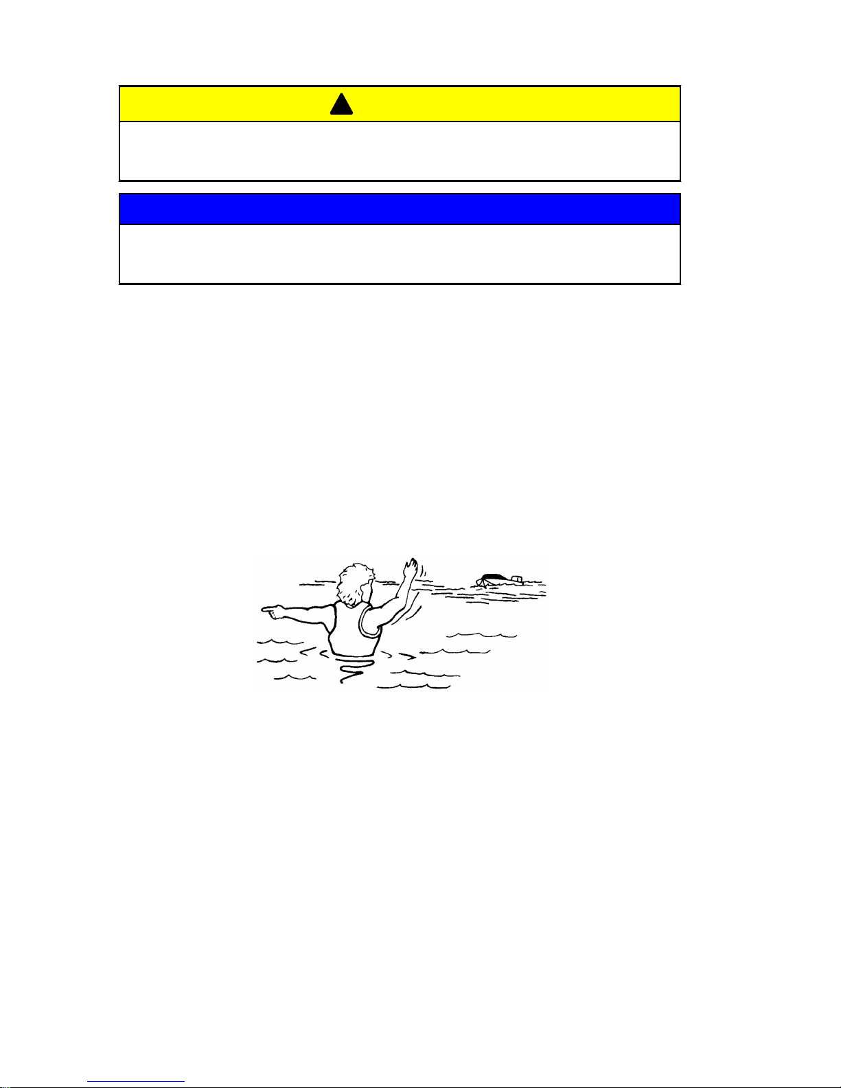
Protecting People In The Water
WHILE YOU ARE CRUISING
It is very difficult for a person standing or floating in the water to
take quick action to avoid a boat heading in his/her direction, even
at slow speed.
21604
Always slow down and exercise extreme caution when boating in
an area where there might be people in the water.
Avoid shallow water or where any loose material such as sand,
shells, seaweed, grass, tree branches, etc., can be pulled in and
expelled from the pump as a high speed projectile.
Page 11

GENERAL INFORMATION
7
WHILE BOAT IS STATIONARY
!
WARNING
Avoid injury resulting from contacting the rotating impeller or
having hair, clothing, or loose objects drawn into the water intake
and wrapping around the impeller shaft. Stay away from the
water intake and never insert an object into the water intake or
water outlet nozzle when the engine is running.
Stop the engine immediately whenever a person is in the water
near the boat. The jet drive is always drawing water through the
water intake when the engine is running. Stay away from the water
intake located under the jet drive and never insert an object into
the water intake or outlet nozzle when the engine is running.
Safe Boating Suggestions
In order to safely enjoy the waterways, the operator should be
familiar with local and other governmental boating regulations and
restrictions, and consider the following suggestions.
Use flotation devices. Have an approved personal flotation device
of suitable size for each person aboard (it is the law) and have it
readily accessible.
Do not overload your boat. Most boats are rated and certified for
maximum load (weight) capacities (refer to your boat capacity
plate). If in doubt, contact your dealer or the boats manufacturer.
Perform safety checks and required maintenance. Follow a regular
schedule and ensure that all repairs are properly made.
Make sure everyone in the boat is properly seated. Do not allow
anyone to sit or ride on any part of the boat that was not intended
for such use. This includes the back of seats, gunwales, transom,
bow, decks, raised fishing seats, any rotating fishing seat; or
anywhere that an unexpected acceleration, sudden stopping,
unexpected loss of boat control, or sudden boat movement could
cause a person to be thrown overboard or into the boat.
Never be under the influence of alcohol or drugs while boating (it
is the law). Alcohol or drug use impairs judgment and greatly
reduces the ability to react quickly.
Page 12

GENERAL INFORMATION
8
Prepare other boat operators. Instruct at least one other person on
board in the basics of starting and operating the jet drive, and boat
handling, in case the driver becomes disabled or falls overboard.
Passenger boarding. Stop the engine whenever passengers are
boarding, unloading, or are near the back (stern) of the boat. Just
shifting the outboard into neutral is not sufficient.
Be alert. The operator of the boat is responsible by law to maintain
a proper lookout by sight and hearing. The operator must have an
unobstructed view particularly to the front. No passengers, load,
or fishing seats should block the operators view when operating
the boat above idle speed.
Avoid shallow water conditions. Never operate the jet drive in
very shallow water or where there is a noticeable amount of floating
debris or weeks. Always be in at least 61 to 91 cm (2 to 3 ft.) of
water. Any loose material such as sand, shells, seaweed, grass,
tree branches, etc., can be pulled in by the pump. This may not
only block the water flow and cause lost of steering control, but can
be expelled from the rear of the pump as a high‑speed projectile.
Watch for boat movement in neutral. When the jet drive is in
neutral, the drive impeller continues to rotate. Although the
approximate balancing of forward and reverse thrust will minimize
boat movement, the boat may tend to move slowly forward or
backward. This is normal for a direct‑drive jet driven boat. The
operator should be aware of this and use caution whenever the
engine is running.
Never drive the boat directly behind a water skier in case the skier
falls. As an example, a boat traveling at 40 km/hr (25 MPH) will
overtake a fallen skier 61 m (200 ft.) in front of the boat in 5
seconds.
Watch fallen skiers. When using the boat for water skiing or similar
activities, always keep a fallen or down skier on the operator's side
of the boat while returning to assist the skier. The operator should
always have the down skier in sight and never back up to the skier
or anyone in the water.
Page 13

GENERAL INFORMATION
9
Report accidents. Boat operators are required by law to file a
Boating Accident Report with their state boating law enforcement
agency when the boat is involved in certain boating accidents. A
boating accident must be reported if 1) there is loss of life or
probable loss of life, 2) there is personal injury requiring medical
treatment beyond first aid, 3) there is damage to boats or other
property where the damage value exceeds $500.00 or 4) there is
complete loss of the boat. Seek further assistance from local law
enforcement.
Specifications
Model Jet 25
Jet power 19 kW (25 hp)
Horsepower 22 kW (30 hp)
Engine idle RPM 950 +/‑ 25 RPM
Full Throttle RPM range 5150‑5850 RPM
Number of cylinders 2
Piston displacement 429 cc (26.3 cu. in.)
Cylinder bore 68 mm (2.68 in.)
Stroke 59 mm (2.32 in.)
Induction system Loop charged with single carburetor
Ignition Capacitor discharge
Alternator Optional 12V/80W/6.7A
Recommended spark plug NGK BR7HS‑10
Spark plug gap 1.0 mm (0.04 in.)
Recommended gasoline Unleaded 87 Octane min.
Recommended oil TCW‑3 pre‑mix (50:1)
Pump type Centrifugal
Impeller 3‑blade stainless steel
Recommended lubricant for the jet pump
driveshaft bearing
Refer to Maintenance
Gear ratio Direct drive
Exhaust system Through‑pump exhaust
Shifting F‑N‑R with side shift
Page 14

GENERAL INFORMATION
10
Components
a
b
c
g
h
i
d
j
k
l
n
o
m
f
e
29515
a - Top cowl
b - Manual start handle
c - Throttle grip
d - Gear shift
e - Lanyard cord
f - Reverse lock lever
g - Tilt pin
h - Jet drive housing
i - Water intake housing
j - Reverse gate
k - Water outlet
l - Driveshaft housing
m -Engine stop switch
n - Choke knob
o - Fuel hose connector
Page 15

OPERATION
11
Lubricating the Driveshaft Bearing
Before each use, lubricate the driveshaft bearing. Refer to
Maintenance - Lubricating the Driveshaft Bearing.
27490
Operating In Freezing Temperatures
If there is a chance of ice forming on the water, the jet drive should
be removed and drained completely of water. If ice should form at
the water level inside the outboard driveshaft housing, it will block
water flow to the engine causing possible damage. Do not start the
engine until the ice is clear.
Pre‑Starting Check List
• Operator knows safe navigation, boating, and operating
procedures.
• An approved personal flotation device of suitable size for each
person aboard and readily accessible (it is the law).
• A ring type life buoy or buoyant cushion designed to be thrown
to a person in the water.
• Know your boats maximum load capacity. Look at the boat
capacity plate.
• Fuel supply OK.
• Ensure the boat drain plug is installed.
• Arrange passengers and load in the boat so the weight is
distributed evenly and everyone is seated in a proper seat.
• Tell someone where you are going and when you expect to
return.
• It is illegal to operate a boat while under the influence of
alcohol or drugs.
Page 16

OPERATION
12
• Know the waters and area you will be boating; tides, currents,
sand bars, rocks, and other hazards.
• Check steering for free operation.
• Check for debris around the rudder and reverse gate which
may jam or hinder operation.
• Before launching, examine the jet drive water intake for
obstructions which may prevent pumping of water.
• Ensure the driveshaft bearing on the jet drive is lubricated.
Operating In Salt Water Or Polluted Water
If the boat is kept moored in the water, always tilt the outboard so
the water intake is completely out of water (except in freezing
temperatures) when not in use.
Wash down the outboard exterior and flush out the exhaust outlet
of the jet drive with fresh water after each use. Each month, spray
Mercury Precision or Quicksilver Corrosion Guard on external
metal surfaces.
Operating In Shallow Water
The life of the impeller and water intake can be greatly increased
by avoiding the intake of sand and gravel. The intake suction will
act like a dredge when the water intake comes close to the bottom.
It is better to stop the engine and drift up to shore when landing,
and to shove off with an oar when leaving. The engine can idle
through areas of water less than 61 cm (2 ft.) deep, but there
should be more than 61 cm (2 ft.) of water under the boat when
increasing speed to reach full plane.
Once the boat is on plane, the boat speed will prevent the ingestion
of gravel and other debris from the bottom. The suction is still
present, but the water intake passes too quickly over the bottom
to allow debris to be drawn into the water intake.
When boating through shallow water areas, choose a course of
travel that avoids sharp rocks and other underwater obstacles that
could damage the boat. Running the boat through these areas on
full plane may be helpful as the boat will be riding higher in the
water. If the boat gets stuck on the bottom, immediately stop the
engine and move the boat to deeper water.
Page 17

OPERATION
13
How the Jet Drive Operates
A jet driven boat has substantially different handling characteristics
compared to a propeller driven boat. It is recommended that the
operator adjusts to these characteristics by experimenting in open
water at both high and low speeds.
The driveshaft driven impeller draws water up through the water
intake and then redirects it at a high pressure through the water
outlet nozzle to create forward thrust. To obtain reverse, the
reverse gate moves over the outlet nozzle to direct the water in the
opposite direction.
a
c
b
29022
a - Water intake
b - Water outlet nozzle
c - Reverse gate
When the jet drive is in neutral, the impeller continues to rotate.
However, the reverse gate is positioned so that some of the
forward thrust is diverted to create reverse thrust. This
approximate balancing of forward and reverse thrust will minimize
any boat movement. Because the impeller is always rotating and
creating thrust when the engine is running, the boat may tend to
move slowly forward or backward. This is normal for a direct‑drive
jet driven boat. The operator should be aware of this and use
caution whenever the engine is running.
Page 18

OPERATION
14
!
WARNING
Avoid injury resulting from contacting the rotating impeller or
having hair, clothing, or loose objects drawn into the water intake
and wrapping around the impeller shaft. Stay away from the
water intake and never insert an object into the water intake or
water outlet nozzle when the engine is running.
The jet drive is always drawing water into the housing when the
engine is running. Do not operate the jet drive with the grate
removed from the water intake. Keep hands, feet, hair, loose
clothing, life jackets, etc., away from the water intake. Never insert
an object into the water intake or water outlet nozzle when the
engine is running.
Stopping the Boat in an Emergency
A jet powered boat has emergency stopping capability unique to
this form of propulsion.
!
WARNING
Using the emergency stopping capability of a jet drive unit will
slow down the boat in an emergency. However, sudden stopping
may cause the occupants of the boat to be thrown forward or out
of the boat resulting in serious injury or death. Use caution when
performing the emergency stopping procedure, and be sure to
practice in a safe area.
In an emergency, putting the jet outboard into reverse and applying
reverse throttle can rapidly slow down the boat and reduce
stopping distance. However, such a maneuver may cause
occupants in the boat to be thrown forward or possibly out of the
boat.
Steering the Boat
The jet drive is dependent on water jet thrust for steering the boat.
If the water jet thrust should ever stop, (water blockage, engine
stops, etc.) will cause the boat to slow to a stop. However, while
slowing there will be a reduced ability to steer the boat.
Page 19

OPERATION
15
!
WARNING
Steering the vessel in a tight turn can result in loss of boat control.
In some cases, the boat can spin out or roll over, causing serious
injury or death. Avoid steering beyond the capabilities of the
vessel, especially at high speeds.
!
WARNING
A loss or reduction in water jet thrust will directly affect boat
directional control, and may result in property damage, personal
injury, or death. Boat directional control can also be substantially
reduced or lost altogether by a sudden loss of power such as
running out of gas, quickly backing off the throttle, turning off the
ignition switch, activating the lanyard stop switch, or plugging the
water intake to the jet pump. Use caution when maneuvering at
high speeds in areas where debris (weeds, logs, gravel, etc.)
could be picked up into the jet drive. The ability to take evasive
action is dependent on sufficient water jet thrust to control the
boat.
While steering the boat at engine speeds above idle, the boat will
respond quickly; but due to the relatively flat‑bottom hulls and lack
of a gearcase in the water, the boat will tend to skid on turns. Turns
must be started early and use sufficient power to maintain steering
control.
Mooring The Boat
Be sure to tilt the jet drive out of the water when the boat is pulled
onto a beach or tied to a dock in shallow water. Failure to do this
may cause the water intake housing to fill with sand or debris and
could prevent the outboard from cranking over for starting.
Page 20

OPERATION
16
Water Intake Blockage
!
WARNING
A rotating impeller could cause injury if contact is made with
hands, clothing, or tools. To avoid injury, keep hands and clothing
away from the inlet or outlet of the jetdrive, regardless of whether
the boat is in the water. Secure tools and loose items to avoid
being struck by projectiles as a result of contact with the rotating
impeller, and to prevent damage to the impeller.
A large amount of debris being drawn into the water intake may
result in a loss of power. Intake suction holding debris against the
grate will result in restricted water flow. Shutting the engine off may
allow the debris to fall off the intake grate allowing full power to be
restored. If debris does not fall off the intake grate, the engine must
be shut off and debris physically removed from the grate.
Clearing A Lodged Impeller
!
WARNING
Rotating the flywheel to free a lodged impeller can accidentally
start the engine, resulting in serious injury or death. Always turn
the ignition key or lanyard stop switch to the "OFF" position and
remove all spark plug leads from the spark plugs.
It is possible for debris to lodge between the impeller and jet
housing wall, especially after the engine has been stopped. This
will lock the driveshaft and will prevent the engine from being able
to crank over for starting. Following are steps for dislodging the
impeller.
1. Position lanyard stop switch to the "OFF" position.
2. Remove spark plug leads to prevent the engine from
accidentally starting.
3. Remove flywheel or rewind cover and rotate the engine
flywheel counterclockwise.
If this does not dislodge the impeller, it will be necessary to remove
the six screws and water intake housing.
Page 21

MAINTENANCE
17
Worn/Dull Impeller
The intake of gravel through the pump can round off and wear the
leading edges of the impeller. Some conditions that could be
experienced from a worn/dull impeller are as follows:
• Noticeable performance loss, especially on acceleration
• Difficulty getting the boat on plane
• An increase in engine RPM at wide open throttle
IMPORTANT: Do not sharpen or alter the top side lifting angle.
Check the impeller blades occasionally for damage. Use a flat file
to resharpen the leading edges. Sharpen to a 0.8 mm (1/32 in.)
radius by removing material from bottom side only.
a
b
29079
a - Leading edge
b - Top side lifting angle
Impeller Clearance Adjustment
The impeller should be adjusted so there is approximately
0.8 mm (0.03 in.) clearance between the impeller edge and liner.
Operating the jet drive in waters that contain sand and gravel can
cause wear to the impeller blades, and the clearance will start to
exceed 0.8 mm (0.03 in.).
Page 22

MAINTENANCE
18
As the blades wear, shims located in the stack outside of the
impeller can be transferred behind the impeller. This will move the
impeller further down into the tapered liner to reduce the clearance.
a
b
29080
a - Shims
b - Clearance between impeller edge and liner
Check the impeller clearance by sliding a feeler gauge through the
intake grate and measure the clearance between the impeller edge
and liner. If adjustment is required, refer to Impeller Removal and
Installation.
Replaceable Jet Drive Shear Key
The jet drive is equipped with a shear key to protect it in the event
of a lodged impeller. The shear key can be reached by removing
the water intake housing and impeller. Refer to Maintenance -
Impeller Removal and Installation.
29174
Page 23

MAINTENANCE
19
Impeller Removal and Installation
!
WARNING
Rotating the driveshaft may cause the engine to crank over and
start. To prevent this type of accidental engine starting and
possible serious injury caused from being struck by a rotating
impeller, always turn the ignition key or lanyard stop switch to the
"OFF" position and remove the spark plug leads from the spark
plugs while servicing the impeller.
1. Shift the outboard to the neutral position.
2. Position the key switch or lanyard stop switch to the "OFF"
position.
3. Remove the spark plug leads to prevent the engine from
starting.
26899
4. Remove the six screws securing the water intake housing, and
remove the water intake housing.
29081
Page 24

MAINTENANCE
20
5. Straighten the bent tabs on the impeller nut retainer and
remove the impeller nut.
b
a
29082
a - Tabs b - Impeller nut
6. Pull the impeller straight off the shaft. If the impeller is tight,
use a hammer and a block of wood to rotate the impeller
clockwise on the shaft until the keyway is directly above the
flat on the shaft. This will free the jammed key and allow
removal.
Shift Link Rod Adjustment
!
WARNING
Pressurized water hitting the reverse gate may cause it to
engage, causing sudden and unexpected slowing of the boat.
This can cause serious injury or death from occupants being
thrown within or out of the boat. Adjust the shift link rod to lock
the reverse gate, preventing it from interfering with water flow.
Page 25

MAINTENANCE
21
CHECKING SHIFT LINK ROD ADJUSTMENT
Check the shift link rod adjustment in forward shift position. The
correct adjustment will position the shift cam far enough on the
roller in order to lock the reverse gate into forward position. The
reverse gate should not be able to be forced up towards neutral.
Pull on the reverse gate by hand to verify.
a
b
c
d
29084
a - Shift link rod
b - Shift cam
c - Roller
d - Reverse gate
ADJUSTING SHIFT LINK ROD
1. Place the shift handle into full forward shift position.
2. Adjust the length of the shift link rod so the roller is at the full
end of travel (bottom) in the shift cam when the shift handle is
in forward.
Corrosion Control Anode
An anode helps protect the outboard against galvanic corrosion by
sacrificing its metal to be slowly corroded instead of the outboard
metals.
Page 26

MAINTENANCE
22
An anode is located on the water intake housing. An anode
requires periodic inspection, especially in salt water which will
accelerate the erosion. To maintain this corrosion protection,
always replace the anode before it is completely eroded. Never
paint or apply a protective coating on the anode as this will reduce
effectiveness of the anode.
a
24838
a - Water intake housing anode
Lubricating the Driveshaft Bearing
Lubricate the driveshaft bearing before each use.
Tube Ref No. Description Where Used Part No.
95
2-4-C with Teflon Driveshaft bearing 92-802859A 1
IMPORTANT: It is important not to use a general all purpose
grease for this bearing. The lubricant recommended is a water
resistant grease of the proper consistency for this application. If a
substitute is used, be sure that it is water resistant and of the same
consistency.
1. Pull the vent hose off of the grease fitting.
2. Pump in grease through the grease fitting, using the grease
gun provided, until excess grease starts to exit the vent hose.
Page 27

MAINTENANCE
23
3. Reconnect the vent hose onto the grease fitting after greasing.
a
b
27491
a - Grease fitting b - Vent hose
NOTE: After 30 hours of operation, pump in extra grease to purge
out any moisture. Visually inspecting the purged grease at this time
will give an indication of conditions inside the bearing housing. A
gradual increase in moisture content indicates seal wear. If the
grease begins to turn dark or dirty gray, the driveshaft bearing and
seals should be inspected and replaced if necessary. Some
discoloration of the grease is normal during the break‑in period on
a new set of seals.
Page 28

TROUBLESHOOTING
24
Engine Over‑Speed (Excessive RPM)
POSSIBLE CAUSES
• Outboard mounted too high on the transom.
• Worn jet pump impeller or liner.
• Incorrect jet pump impeller clearance adjustment.
• Tilting the outboard out beyond a vertical position.
• Cavitation of the impeller due to rough water or obstruction in
the boat hull.
• Blockage of the water intake.
Performance Loss
POSSIBLE CAUSES
• Throttle not fully open.
• Damaged impeller.
• Incorrect engine timing, adjustments, or setup.
• Boat overloaded or load improperly distributed.
• Excessive water in bilge.
• Boat bottom is dirty or damaged.
Page 29

ENGINE INSTALLATION
25
Determining the Mounting Height of the Outboard
The following outboard mounting height settings will work good for
most applications, however, because of different boat/hull designs,
the setting should be rechecked by test running the boat. Refer to
Water Testing.
• Installing the outboard too high on the transom will allow the
water intake to suck in air and cause cavitation. Cavitation
causes the engine to overspeed in spurts and reduce thrust.
This condition should be avoided by proper height setting.
• Installing the outboard too low on the transom will allow
excessive drag.
BOATS WITH A "V" BOTTOM HULL
1. Measure the width of the leading edge on the water intake
housing. Make a horizontal line on the transom up from the
"V" bottom the same length as the width of the water intake
housing.
a
b
22401
a - Horizontal line
b - Width of the leading edge on the water intake housing
2. Place (center) the outboard on the boat transom. Set the
height of the outboard on the boat transom so that the front
edge of the water intake housing is in line with the horizontal
line made in step 1. Fasten the outboard to the transom at this
height.
Page 30

ENGINE INSTALLATION
26
BOATS WITH A FLAT BOTTOM HULL
1. Place (center) the outboard on the boat transom. Set the
height of the outboard on the boat transom so that the front
edge of the water intake housing is in line with the bottom of
the boat as shown. Fasten outboard to the transom at this
height.
22403
Water Testing
CHECKING FOR CAVITATION
The initial outboard height setting should be close to the optimum
setting for the outboard. However, because of the hull design of
some boats, obstructions, or imperfections in the hull ahead of the
water intake, adjustments may be required to prevent cavitation at
running speeds.
When operating the boat, the outboard driveshaft housing should
be vertical, or tilted toward the boat, when planing to provide a
scooping angle on the water intake. Tilting the outboard out beyond
a vertical position reduces the scoop angle and can cause impeller
slippage and cavitation.
IMPORTANT: If the angle of the boat transom does not allow the
driveshaft housing to be positioned vertical, a wedge kit should be
installed behind the transom brackets to increase the tilt‑in angle.
NOTE: Slight cavitation in sharp turns and rough water is
acceptable, but excessive cavitation is harmful to the outboard and
should be avoided.
Test run the boat. If cavitation occurs (air enters the pump), the
first thing to try is lowering the outboard mounting height.
Page 31

ENGINE INSTALLATION
27
If cavitation still exists after lowering the outboard, it may be helpful
to seek advice from the boat manufacturer.
Another option to further reduce cavitation is a rough water plate.
A rough water plate may be helpful in reducing cavitation when
running in windy, rough water conditions where air is sucked into
the water intake when jumping waves. Install a 0.8 mm (1/32 in.)
metal plate that extends from the hull bottom to the top of the water
intake housing. This plate tends to reduce air intake as well as
reduce spray.
a
24906
a - Rough water plate
 Loading...