

Page 1
Warranty Message
The product you have purchased comes with a limited warranty from Mercury Marine; the terms of the warranty are set
forth in the Warranty Information section of this manual. The
warranty statement contains a description of what is covered,
what is not covered, the duration of coverage, how to best
obtain warranty coverage, important disclaimers and limita-
tions of damages, and other related information. Please
review this important information.
WARNING
The operator (driver) is responsible for the correct and
safe operation of the boat, the equipment aboard and the
safety of all occupants aboard. We strongly recommend
that the operator read this Operation and Maintenance
Manual and thoroughly understand the operational instructions for the power package and all related accessories before the boat is used.
WARNING
The engine exhaust from this product contains chemicals known to the state of California to cause cancer,
birth defects or other reproductive harm.
The description and specifications contained herein were in effect at the time
this guide was approved for printing. Mercury Marine, whose policy is one of
continuous improvement, reserves the right to discontinue models at any
time, or to change specifications or designs, without notice and without incurring obligation.
Mercury Marine, Fond du Lac, Wisconsin, U.S.A. Printed in U.S.A.
2001, Mercury Marine
The following are registered trademarks of Brunswick Corporation: Autoblend, Jet-Prop, Mariner, Merc, MerCathode, MerCruiser, Mercury, Mercury
Marine, Mercury Precision Parts, Mercury Racing, Quicksilver, Ride-Guide,
and Thruster.
90-840175021 601
HP 500 EFI Bravo XR/XZ/III
2001 Mercury Marine
Page 2

–2 500 EFI Bravo
Page 3

–1500 EFI Bravo
for your purchase of one of the finest marine power packages
available. It incorporates numerous design features to assure operating ease and durability.
With proper care and maintenance, you will thoroughly enjoy
using this product for many boating seasons. To ensure maximum performance and carefree use, we ask that you thoroughly read this manual.
The Operation and Maintenance Manual contains specific instructions for using and maintaining your product. We suggest that this manual remain with the product for ready reference whenever you are on the water.
Again, thank you for purchasing one of our MerCruiser products. We sincerely hope your boating will be pleasant!
Mercury Racing,
N7480 County Road “UU”
Fond du Lac, WI 54935-9585
Page 4

0 500 EFI Bravo
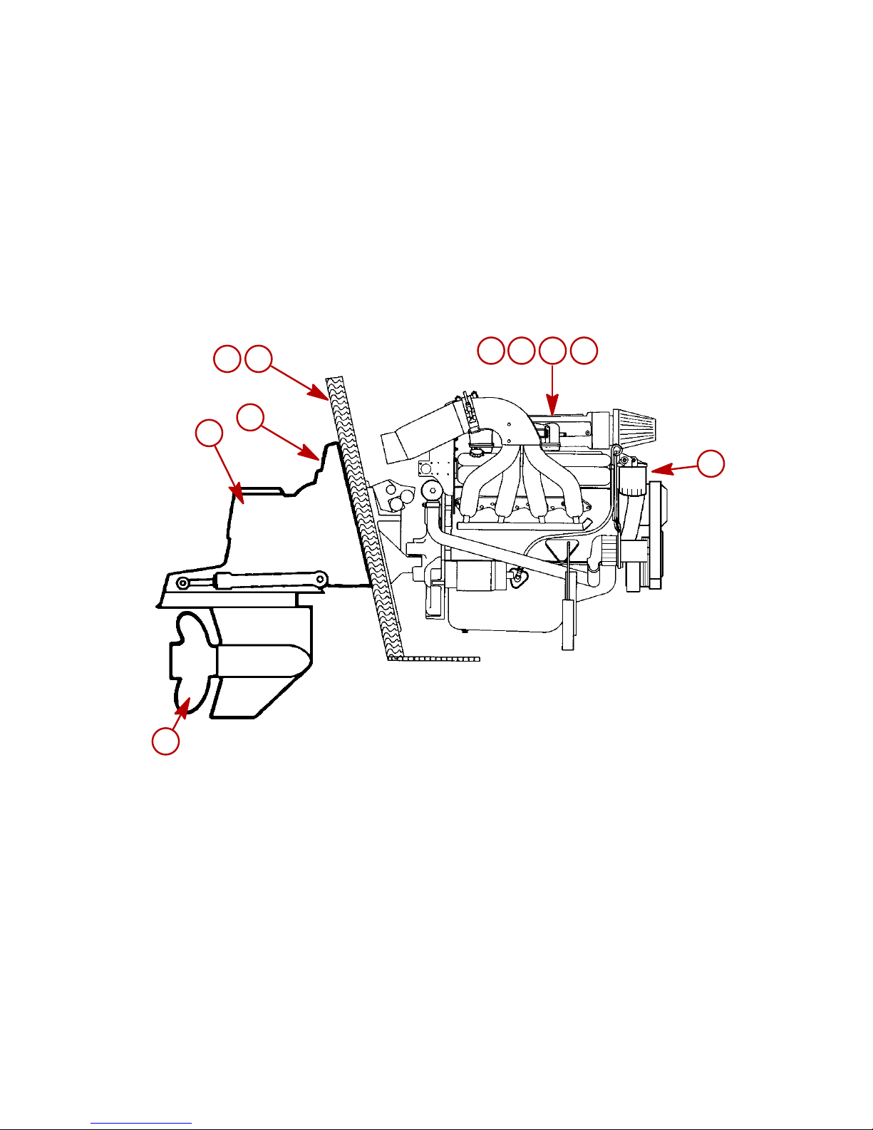
IDENTIFICATION RECORD
PLEASE RECORD THE FOLLOWING INFORMATION:
1 Engine Model/Horsepower:
2 Engine S/N:
3 Transom Assembly S/N:
4 Stern Drive S/N & Gear Ratio:
5 Propeller Number/Pitch:
6 Hull ID Number:
7 Boat Model & Length:
SERIAL NUMBERS
The serial numbers are the manufacturer’s keys to numerous engineering details
which apply to your MerCruiser
power package. When contacting your Authorized
MerCruiser Dealer about service, always specify model and serial numbers.
Page 5
1500 EFI Bravo
4321
2
3
4
5
76
Page 6

2 500 EFI Bravo
CB128
TABLE OF CONTENTS
Page
Warranty Information
Warranty Registration 5. . . . . . . . . . . . . . . . . . . . . . . . . . . . . . .
Transfer Of Warranty 7. . . . . . . . . . . . . . . . . . . . . . . . . . . . . . . .
Mercury RACING DIVISION One Year Limited Warranty 8.
3 Year Limited Warranty Against Corrosion (Worldwide) 12.
Warranty Coverage and Exclusions for Mercury Racing
Outboard and Sterndrive Products 15. . . . . . . . . . . . . . . . . . . .
General Information
Boater’s Responsibilities 17. . . . . . . . . . . . . . . . . . . . . . . . . . . . .
Before Operating Your Boat 17. . . . . . . . . . . . . . . . . . . . . . . . . .
Boat Horsepower Capacity 18. . . . . . . . . . . . . . . . . . . . . . . . . . .
High-Speed and High-Performance Boat Operation 18. . . . .
Lanyard Stop Switch 19. . . . . . . . . . . . . . . . . . . . . . . . . . . . . . . .
Trailering Boat 20. . . . . . . . . . . . . . . . . . . . . . . . . . . . . . . . . . . . .
Protecting People In The Water 21. . . . . . . . . . . . . . . . . . . . . . .
Carbon Monoxide Risk 23. . . . . . . . . . . . . . . . . . . . . . . . . . . . . .
Wave And Wake Jumping 24. . . . . . . . . . . . . . . . . . . . . . . . . . .
Impact With Underwater Hazards 25. . . . . . . . . . . . . . . . . . . . .
Operating In Shallow Water 27. . . . . . . . . . . . . . . . . . . . . . . . . .
Safe Boating Suggestions 28. . . . . . . . . . . . . . . . . . . . . . . . . . .
Stolen Power Package 30. . . . . . . . . . . . . . . . . . . . . . . . . . . . . .
Specifications
Fuel Requirements 31. . . . . . . . . . . . . . . . . . . . . . . . . . . . . . . . .
Crankcase Oil 34. . . . . . . . . . . . . . . . . . . . . . . . . . . . . . . . . . . . . .
Capacities 35. . . . . . . . . . . . . . . . . . . . . . . . . . . . . . . . . . . . . . . . .
Engine Specifications 36. . . . . . . . . . . . . . . . . . . . . . . . . . . . . . .
Tune Up Specifications 37. . . . . . . . . . . . . . . . . . . . . . . . . . . . . .
Operation
Engine Break-In 39. . . . . . . . . . . . . . . . . . . . . . . . . . . . . . . . . . . .
After Break-In Period 39. . . . . . . . . . . . . . . . . . . . . . . . . . . . . . . .
Instrumentation 41. . . . . . . . . . . . . . . . . . . . . . . . . . . . . . . . . . . . .
Audio Warning System 43. . . . . . . . . . . . . . . . . . . . . . . . . . . . . .
Electrical System Overload Protection 45. . . . . . . . . . . . . . . . .
Remote Controls (Panel Mounted) 47. . . . . . . . . . . . . . . . . . . .
Remote Controls (Console Mounted) 49. . . . . . . . . . . . . . . . . .
(continued on next page)
Page 7

3500 EFI Bravo
TABLE OF CONTENTS
Page
Operation (cont.)
Remote Controls (Console Mounted Zero Effort) 51. . . . . . . .
Power Trim 53. . . . . . . . . . . . . . . . . . . . . . . . . . . . . . . . . . . . . . . .
Starting, Shifting and Stopping 64. . . . . . . . . . . . . . . . . . . . . . .
Starting/Operation Chart Checklist 66. . . . . . . . . . . . . . . . . . . .
Freezing Temperature Operation 66. . . . . . . . . . . . . . . . . . . . .
Drain Plug and Bilge Pump 67. . . . . . . . . . . . . . . . . . . . . . . . . .
Launching And Boat Operation Care 67. . . . . . . . . . . . . . . . . .
Conditions Affecting Operation
Weight Distribution 68. . . . . . . . . . . . . . . . . . . . . . . . . . . . . . . . . .
Bottom Of Boat 68. . . . . . . . . . . . . . . . . . . . . . . . . . . . . . . . . . . . .
Cavitation 69. . . . . . . . . . . . . . . . . . . . . . . . . . . . . . . . . . . . . . . . .
Ventilation 69. . . . . . . . . . . . . . . . . . . . . . . . . . . . . . . . . . . . . . . . .
Propeller Selection 70. . . . . . . . . . . . . . . . . . . . . . . . . . . . . . . . . .
Conditions That Lower Engine Performance 71. . . . . . . . . . . .
Maintenance
Operation And Maintenance 72. . . . . . . . . . . . . . . . . . . . . . . . .
Replacement Service Parts 73. . . . . . . . . . . . . . . . . . . . . . . . . .
Do-It-Yourself Maintenance Suggestions 74. . . . . . . . . . . . . . .
Maintenance Charts 77. . . . . . . . . . . . . . . . . . . . . . . . . . . . . . . .
Checking Fluid Levels 83. . . . . . . . . . . . . . . . . . . . . . . . . . . . . . .
Changing Fluids 89. . . . . . . . . . . . . . . . . . . . . . . . . . . . . . . . . . . .
Lubrication 94. . . . . . . . . . . . . . . . . . . . . . . . . . . . . . . . . . . . . . . . .
Propellers 99. . . . . . . . . . . . . . . . . . . . . . . . . . . . . . . . . . . . . . . . .
Flushing Cooling System 107. . . . . . . . . . . . . . . . . . . . . . . . . . . .
Seawater Pump Impeller Inspection 107. . . . . . . . . . . . . . . . . . .
Cleaning Seawater (Raw Water) Section of Oil Cooler 109. . .
Changing Positive Crankcase Ventilation Valve 109. . . . . . . . .
Drive Belt 111. . . . . . . . . . . . . . . . . . . . . . . . . . . . . . . . . . . . . . . . . .
Fuel Filters 112. . . . . . . . . . . . . . . . . . . . . . . . . . . . . . . . . . . . . . . .
Corrosion and Corrosion Protection 113. . . . . . . . . . . . . . . . . . .
Battery 118. . . . . . . . . . . . . . . . . . . . . . . . . . . . . . . . . . . . . . . . . . . .
Bottom of Boat 119. . . . . . . . . . . . . . . . . . . . . . . . . . . . . . . . . . . . .
Inspection of Power Package 119. . . . . . . . . . . . . . . . . . . . . . . .
Attention Required After Submersion 119. . . . . . . . . . . . . . . . . .
Maintenance Log 120. . . . . . . . . . . . . . . . . . . . . . . . . . . . . . . . . . .
Page 8

4 500 EFI Bravo
TABLE OF CONTENTS
Page
Cold Weather or Extended Storage
Power Package Lay-up 122. . . . . . . . . . . . . . . . . . . . . . . . . . . . . .
Draining Instructions 125. . . . . . . . . . . . . . . . . . . . . . . . . . . . . . . .
Battery Winter Storage 128. . . . . . . . . . . . . . . . . . . . . . . . . . . . . .
Power Package Recommissioning 128. . . . . . . . . . . . . . . . . . . .
Troubleshooting
Starter Motor Will Not Crank Engine, or Cranks Slow 129. . . .
Engine Will Not Start or Is Hard to Start 129. . . . . . . . . . . . . . . .
Engine Runs Rough, Misses, and/or Backfires 130. . . . . . . . . .
Poor Performance 131. . . . . . . . . . . . . . . . . . . . . . . . . . . . . . . . . .
Excessive Engine Temperature 131. . . . . . . . . . . . . . . . . . . . . . .
Insufficient Engine Temperature 132. . . . . . . . . . . . . . . . . . . . . .
Low Engine Oil Pressure 132. . . . . . . . . . . . . . . . . . . . . . . . . . . .
Battery Will Not Come Up On Charge 132. . . . . . . . . . . . . . . . .
Power Trim Does Not Operate (Motor Doesn’t Run) 133. . . . .
Power Trim Does Not Operate (Motor Runs But Drive Unit
Does Not Move) 133. . . . . . . . . . . . . . . . . . . . . . . . . . . . . . . . . . . .
Remote Control Operates Hard, Binds, Has Excessive Free-
Play or Makes Unusual Sounds 134. . . . . . . . . . . . . . . . . . . . . .
Steering Wheel Turns Hard or Jerky 134. . . . . . . . . . . . . . . . . .
Block Water Pressure Is Below Specification 135. . . . . . . . . . .
Block Water Pressure Is Above Specification 135. . . . . . . . . . .
Water Flow Diagram
500 EFI Engine 136. . . . . . . . . . . . . . . . . . . . . . . . . . . . . . . . . . . . .
Wiring Diagrams
Power Trim (Single Engine) 137. . . . . . . . . . . . . . . . . . . . . . . . . .
Power Trim (Dual Engine) 138. . . . . . . . . . . . . . . . . . . . . . . . . . .
Instrument Wiring Harness 139. . . . . . . . . . . . . . . . . . . . . . . . . . .
Owner Service Assistance
Owner Service Assistance 140. . . . . . . . . . . . . . . . . . . . . . . . . . .
Ordering Literature
Ordering Literature 144. . . . . . . . . . . . . . . . . . . . . . . . . . . . . . . . . .
Page 9

5500 EFI Bravo
WARRANTY INFORMATION
ou1
Warranty Registration
UNITED STATES AND CANADA
1. It is important that your selling dealer fills out the Warranty Regis-
tration Card completely and mails it to the factory immediately
upon sale of the new product.
2. It identifies name and address of the original purchaser, product
model and serial number(s), date of sale, type of use and selling
dealer’s code, name and address. The dealer also certifies that
you are the original purchaser and user of the product.
3. Upon receipt of the W arranty Registration Card at the factory, you
will be issued a plastic Owner W arranty Registration Card which
is your only valid registration identification. It must be presented
to the servicing dealer should warranty service be required. Warranty claims will not be accepted without presentation of this
card.
4. A temporary Owner Warranty Registration Card will be pres-
ented to you when you purchase the product. It is valid only for
30 days from date of sale while your plastic Owner Warranty Registration Card is being processed. Should your product need service during this period, present the temporary registration card
to the dealer. He will attach it to your warranty claim form.
5. Because of your selling dealer’s continuing personal interest in
your satisfaction, the product should be returned to him for warranty service.
6. If your plastic card is not received within 30 days from date of new
product sale, please contact your selling dealer.
7. The product warranty is not effective until the product is regis-
tered at the factory.
NOTE: Registration lists must be maintained by factory and dealer
on marine products sold in the United States, should notification under the Federal Boat Safety Act be required.
Page 10

6 500 EFI Bravo
WARRANTY INFORMATION
ou2
Warranty Registration (cont.)
OUTSIDE THE UNITED STATES AND CANADA
1. It is important that your selling dealer fills out the Warranty Regis-
tration Card completely and mails it to the distributor or Marine
Power Service Center responsible for administering the warranty
registration/claim program for your area.
2. The Warranty Registration Card identifies your name and ad-
dress, product model and serial number(s), date of sale, type of
use and the selling distributor’s/dealer’s code number, name and
address. The distributor/dealer also certifies that you are the
original purchaser and user of the product.
3. A copy of the Warranty Registration Card, designated as the
“Purchaser’s Copy”, MUST be given to you immediately after the
card has been completely filled out by the selling distributor/dealer. This card represents your factory registration identification,
and should be retained by you for future use when required.
Should you ever require warranty service on this product, your
dealer may ask you for the Warranty Registration Card to verify
date of purchase and to use the information on the card to prepare the warranty claim form(s).
4. In some countries, the Marine Power Service Center will issue
you a permanent (plastic) Warranty Registration Card within 30
days after receiving the “Factory Copy” of the W arranty Registration Card from your distributor/dealer. If you receive a plastic
Warranty Registration Card, you may discard the “Purchaser’s
Copy” that you received from the distributor/dealer when you purchased the product. Ask your distributor/dealer if this plastic card
program applies to you.
5. For further information concerning the Warranty Registration
Card and its relationship to Warranty Claim processing, refer to
the “International Warranty”.
IMPORTANT: Registration lists must be maintained by the factory and dealer in some countries by law . It is our desire to have
ALL products registered at the factory should it ever be necessary to contact you. Make sure your dealer/distributor fills out
the warranty registration card immediately and sends the factory copy to the Marine Power International Service Center for
your area.
Page 11

7500 EFI Bravo
WARRANTY INFORMATION
oq2
Transfer Of Warranty
The limited warranty is transferable to a subsequent purchaser, but
only for the remainder of the unused portion of the limited warranty.
This will not apply to products used for commercial applications.
DIRECT SALE BY OWNER
The second owner can be registered as the new owner and retain the
unused portion of the limited warranty by sending the former owner’s
plastic Owner Warranty Registration Card and a copy of the bill of
sale to show proof of ownership. In the United States and Canada,
mail to:
Mercury Marine
W6250 W. Pioneer Road
P.O. Box 1939
Fond du Lac, WI 54936-1939
Attn: Warranty Registration Department
A new Owner Warranty Registration Card will be issued with the ne w
owner’s name and address. Registration records will be changed on
the factory computer registration file.
There is no charge for this service.
For products purchased outside the United States and Canada, con-
tact the distributor in your country, or the Mercury Marine Service Office closest to you.
Page 12

8 500 EFI Bravo
WARRANTY INFORMATION
Mercury RACING DIVISION One Year Limited
Wa rranty
WHAT IS COVERED
Mercury Marine warrants its new products to be free of defects in ma terial and workmanship during the period described below.
DURATION OF COVERAGE
This Limited W arranty provides coverage for one (1) year from either
the date the product is first sold to a recreational use retail purchaser ,
or the date on which the product is first put into service, whichever
occurs first. The repair or replacement of parts, or the performance
of service under this warranty, does not extend the life of this warranty beyond its original expiration date. Unexpired warranty coverage
can be transferred to a subsequent purchaser upon proper re-registration of the product.
CONDITIONS THAT MUST BE MET IN ORDER TO OBTAIN
WARRANTY COVERAGE
Warranty coverage is available only to retail customers that purchase from a Dealer authorized by Mercury Marine to distribute the
product in the country in which the sale occurred, and then only after
the Mercury Marine specified pre-delivery inspection process is
completed and documented. Warranty coverage becomes available
upon proper registration of the product by the authorized dealer. Inaccurate warranty registration information regarding recreational
use, or subsequent change of use from recreational to commercial
may void the warranty at the sole discretion of Mercury Marine. Routine maintenance outlined in the Operation, Maintenance and Warranty Manual must be timely performed in order to maintain warranty
coverage. Mercury Marine reserves the right to make warranty coverage contingent upon proof of proper maintenance.
Page 13

9500 EFI Bravo
WARRANTY INFORMATION
Mercury RACING DIVISION One Year Limited
Warranty (cont.)
WHAT MERCURY WILL DO
Mercury’s sole and exclusive obligation under this warranty is limited
to, at our option, repairing a defective part, replacing such part or
parts with new or Mercury Marine certified re-manufactured parts, or
refunding the purchase price of the Mercury product. Mercury reserves the right to improve or modify products from time to time without assuming an obligation to modify products previously manufactured.
HOW TO OBTAIN WARRANTY COVERAGE
The customer must provide Mercury with a reasonable opportunity
to repair and reasonable access to the product for warranty service.
Warranty claims shall be made by delivering the product for inspection to a Mercury dealer authorized to service the product. If purchaser cannot deliver the product to such a dealer, written notice must be
given to Mercury. W e will then arrange for the inspection and any covered repair. Purchaser in that case shall pay for all related transportation charges and/or travel time. If the service provided is not covered
by this warranty , purchaser shall pay for all related labor and material, and any other expenses associated with that service. Purchaser
shall not, unless requested by Mercury, ship the product or parts of
the product directly to Mercury . The warranty registration card is the
only valid registration identification and must be presented to the
dealer at the time warranty service is requested in order to obtain
coverage.
Page 14

10 500 EFI Bravo
WARRANTY INFORMATION
Mercury RACING DIVISION One Year Limited
Warranty (cont.)
WHAT IS NOT COVERED
This limited warranty does not cover routine maintenance items, tune
ups, adjustments, normal wear and tear, damage caused by abuse,
abnormal use, use of a propeller or gear ratio that does not allow the
engine to run in its recommended wide-open-throttle rpm range (see
the Operation, Maintenance & Warranty Manual), operation of the
product in a manner inconsistent with the recommended operation/
duty cycle section of the Operation, Maintenance & Warranty Manual, neglect, accident, submersion, improper installation (proper
installation specifications and techniques are set forth in the installation instructions for the product), improper service, use of an accessory or part not manufactured or sold by us, operation with fuels, oils
or lubricants which are not suitable for use with the product (see the
Operation, Maintenance & Warranty Manual), alteration or removal
of parts, water entering the engine through the fuel intake, air intake
or exhaust system, or damage to the product from insufficient cooling
water caused by blockage of the cooling system by a foreign body,
running the engine out of water, mounting the drive too high on the
transom, or running the boat with the drive trimmed out too far. The
commercial use of the product, defined as any work or employment
related use of the product, or any income generating use of the product, even if such use is only occasional, will void the warranty. Use
of the product for racing or other competitive activity, at any point,
even by a prior owner of the product, voids the warranty.
Expenses related to haul-out, launch, towing, storage, telephone,
rental, inconvenience, slip fees, insurance coverage, loan payments, loss of time, loss of income, or any other type of incidental or
consequential damages are not covered by this warranty. Also, expenses associated with the removal and/or replacement of boat
partitions or material caused by boat design for access to the product
are not covered by this warranty.
Page 15

11500 EFI Bravo
WARRANTY INFORMATION
Mercury RACING DIVISION One Year Limited
Warranty (cont.)
No individual or entity, including Mercury Marine authorized dealers,
has been given authority by Mercury Marine to make any affirmation,
representation or warranty regarding the product, other than those
contained in this limited warranty, and if made, shall not be enforceable against Mercury Marine.
For additional information regarding events and circumstances covered by this warranty, and those that are not, see the Warranty Coverage section of the Operation, Maintenance &Warranty Manual, incorporated by reference into this warranty.
DISCLAIMERS AND LIMITATIONS
THE IMPLIED W ARRANTIES OF MERCHANTABILITY AND FIT-
NESS FOR A PARTICULAR PURPOSE ARE EXPRESSLY DISCLAIMED. TO THE EXTENT THAT THEY CANNOT BE DISCLAIMED, THE IMPLIED WARRANTIES ARE LIMITED IN
DURA TION TO THE LIFE OF THE EXPRESS WARRANTY. INCIDENTAL AND CONSEQUENTIAL DAMAGES ARE EXCLUDED
FROM COVERAGE UNDER THIS WARRANTY. SOME STATES/
COUNTRIES DO NOT ALLOW FOR THE DISCLAIMERS, LIMITATIONS AND EXCLUSIONS IDENTIFIED ABOVE, AS A RESULT, THEY MAY NOT APPLY TO YOU. THIS WARRANTY
GIVES YOU SPECIFIC LEGAL RIGHTS, AND YOU MAY ALSO
HA VE OTHER LEGAL RIGHTS WHICH VARY FROM STA TE TO
STATE AND COUNTRY TO COUNTRY.
PRODUCTS SOLD TO GOVERNMENT AGENCIES
Contact the Mercury Racing Sales Department for a copy of the Government Agencies W arranty Packet Kit which explains the conditions
required for government agencies to receive warranty when purchasing Mercury Racing Outboard or Sterndrive product.
Mercury Racing
Sales Department
N7480 County Rd. UU
Fond du Lac, WI 54935-9585
Phone: 920-921-5330 Fax: 920-921-6533
Page 16

12 500 EFI Bravo
WARRANTY INFORMATION
3 Year Limited Warranty Against Corrosion
(Worldwide)
WHAT IS COVERED
Mercury Marine warrants that each new Mercury, Mariner, Mercury
Racing, Sport Jet, M
2
Jet Drive, Tracker by Mercury Marine Outboard, MerCruiser Inboard or Sterndrive engine (Product) will not be
rendered inoperative as a direct result of corrosion for the period of
time described below.
DURATION OF COVERAGE
This limited corrosion warranty provides coverage for three (3) years
from either the date the product is first sold, or the date on which the
product is first put into service, whichever occurs first. The repair or
replacement of parts, or the performance of service under this warranty does not extend the life of this warranty beyond its original expiration date. Unexpired warranty coverage can be transferred to
subsequent (noncommercial use) purchaser upon proper re-registration of the product.
CONDITIONS THAT MUST BE MET IN ORDER TO OBTAIN
WARRANTY COVERAGE
Warranty coverage is available only to retail customers that purchase from a Dealer authorized by Mercury Marine to distribute the
product in the country in which the sale occurred, and then only after
the Mercury Marine specified pre-delivery inspection process is
completed and documented. Warranty coverage becomes available
upon proper registration of the product by the authorized dealer. Corrosion prevention devices specified in the Operation, Maintenance
&Warranty Manual must be in use on the boat, and routine maintenance outlined in the Operation, Maintenance &Warranty Manual
must be timely performed (including without limitation the replacement of sacrificial anodes, use of specified lubricants, and touch-up
of nicks and scratches) in order to maintain warranty coverage. Mercury Marine reserves the right to make warranty coverage contingent
upon proof of proper maintenance.
Page 17

13500 EFI Bravo
WARRANTY INFORMATION
3 Year Limited Warranty Against Corrosion
(Worldwide) (cont.)
WHAT MERCURY WILL DO
Mercury’s sole and exclusive obligation under this warranty is limited
to, at our option, repairing a corroded part, replacing such part or
parts with new or Mercury Marine certified re-manufactured parts, or
refunding the purchase price of the Mercury product. Mercury reserves the right to improve or modify products from time to time without assuming an obligation to modify products previously manufactured.
HOW TO OBTAIN WARRANTY COVERAGE
The customer must provide Mercury with a reasonable opportunity
to repair, and reasonable access to the product for warranty service.
Warranty claims shall be made by delivering the product for inspection to a Mercury dealer authorized to service the product. If purchaser cannot deliver the product to such a dealer, written notice must be
given to Mercury. W e will then arrange for the inspection and any covered repair. Purchaser in that case shall pay for all related transportation charges and/or travel time. If the service provided is not covered
by this warranty , purchaser shall pay for all related labor and material, and any other expenses associated with that service. Purchaser
shall not, unless requested by Mercury, ship the product or parts of
the product directly to Mercury . The warranty registration card is the
only valid registration identification and must be presented to the
dealer at the time warranty service is requested in order to obtain
coverage.
WHAT IS NOT COVERED
This limited warranty does not cover electrical system corrosion; corrosion resulting from damage, corrosion which causes purely cosmetic damage, abuse or improper service; corrosion to accessories,
instruments, steering systems; corrosion to factory installed jet drive
unit; damage due to marine growth; product sold with less than a one
year limited Product warranty; replacement parts (parts purchased
by customer); products used in a commercial application. Commercial use is defined as any work or employment related use of the
product, or any use of the product which generates income, for any
part of the warranty period, even if the product is only occasionally
used for such purposes.
Page 18

14 500 EFI Bravo
WARRANTY INFORMATION
3 Year Limited Warranty Against Corrosion
(Worldwide) (cont.)
Corrosion damage caused by stray electrical currents (on-shore
power connections, nearby boats, submerged metal) is not covered
by this corrosion warranty and should be protected against by the
use of a corrosion protection system, such as the Mercury Precision
Parts or Quicksilver MerCathode system and/or Galvanic Isolator.
Corrosion damage caused by improper application of copper base
anti-fouling paints is also not covered by this limited warranty. If antifouling protection is required, Tri-Butyl-Tin-Adipate (TBTA) base
anti-fouling paints are recommended on Outboard and MerCruiser
boating applications. In areas where TBTA base paints are prohibited by l a w, copper base paints can be used on the hull and transom.
Do not apply paint to the outboard or MerCruiser product. In addition,
care must be taken to avoid an electrical interconnection between
the warranted product and the paint. For MerCruiser product, an unpainted gap of at least 1.5 inches (38 mm) should be left around the
transom assembly. Refer to the Operation, Maintenance & Warranty
Manual for additional details.
For additional information regarding events and circumstances covered by this warranty, and those that are not, see the Warranty Coverage section of the Operation, Maintenance & W arranty Manual, incorporated by reference into this warranty.
DISCLAIMERS AND LIMITATIONS
THE IMPLIED W ARRANTIES OF MERCHANTABILITY AND FIT-
NESS FOR A PARTICULAR PURPOSE ARE EXPRESSLY DISCLAIMED. TO THE EXTENT THAT THEY CANNOT BE DISCLAIMED, THE IMPLIED WARRANTIES ARE LIMITED IN
DURA TION TO THE LIFE OF THE EXPRESS WARRANTY. INCIDENTAL AND CONSEQUENTIAL DAMAGES ARE EXCLUDED
FROM COVERAGE UNDER THIS WARRANTY. SOME STATES/
COUNTRIES DO NOT ALLOW FOR THE DISCLAIMERS, LIMITATIONS AND EXCLUSIONS IDENTIFIED ABOVE, AS A RESULT, THEY MAY NOT APPLY TO YOU. THIS WARRANTY
GIVES YOU SPECIFIC LEGAL RIGHTS, AND YOU MAY ALSO
HA VE OTHER LEGAL RIGHTS WHICH VARY FROM STA TE TO
STATE AND COUNTRY TO COUNTRY.
Page 19

15500 EFI Bravo
WARRANTY INFORMATION
Warranty Coverage and Exclusions for Mercury
Racing Outboard and Sterndrive Products
The purpose of this section is to help eliminate some of the more
common misunderstandings regarding warranty coverage. The following information explains some of the types of services that are not
covered by warranty. The provisions set forth following have been incorporated by reference into the Mercury Racing Division Three Year
Limited Warranty Against Corrosion Failure, the Mercury Racing
Division 90 Day and One Year Limited Warranties.
Keep in mind that warranty covers repairs that are needed within the
warranty period because of defects in material and workmanship. Installation errors, accidents, normal wear, and a variety of other
causes that affect the product are not covered.
Warranty is limited to defects in material or workmanship, but only to
retail customers that purchase from a Dealer authorized by Mercury
Marine to distribute the product in the country in which the sale occurred, and then only after the Mercury Marine specified pre-delivery
inspection process is completed and documented.
Should you have any questions concerning warranty coverage, contact your authorized dealer. They will be pleased to answer any questions that you may have.
GENERAL EXCLUSIONS FROM WARRANTY
1 Corrosion damage incurred by your 900 SC MerCruiser prod-
uct(s) is not covered under this warranty.
2 Minor adjustments and tune-ups, including checking, cleaning or
adjusting spark plugs, ignition components, carburetor or EFI
settings, filters, belts, controls, and checking lubrication made in
connection with normal services.
3 Damage caused by lack of maintenance.
4 Haul-out, launch, towing charges, and all related transportation
charges and/or travel time, etc.
5 Additional service work requested by customer other than that
necessary to satisfy the warranty obligation.
Page 20

16 500 EFI Bravo
WARRANTY INFORMATION
Warranty Coverage and Exclusions for Mercury
Racing Outboard and Sterndrive Products
(cont.)
6
Labor performed by other than an authorized dealer may be covered only under following circumstances: When performed on
emergency basis (providing there are no authorized dealers in
the area who can perform the work required or have no facilities
to haul out, etc., and prior factory approval has been given to
have the work performed at this facility).
7 Use of other than Mercury Precision or Quicksilver parts when
making warranty repairs.
8 Engine noise does not necessarily indicate a serious engine
problem. If diagnosis indicates a serious internal engine condition which could result in a failure, condition responsible for noise
should be corrected under the warranty.
9 Lower unit and/or propeller damage caused by striking a sub-
merged object is considered a marine hazard.
10Water in the starter motor.
11 Starter motors and/or armatures or field coil assembly, which are
burned, or where lead is thrown out of commutator because of
excess cranking.
12Valve or valve seat grinding required because of wear.
13Removal of the tamper proof seals without prior pre-approval
from Mercury Racing.
Page 21
17500 EFI Bravo
GENERAL INFORMATION
oba1
Boater’s Responsibilities
The boat driver is responsible for correct and safe operation of the
boat and safety of its occupants and general public. It is strongly recommended that each operator (driver) read and understand this entire manual before operating the outboard.
Be sure at least one additional person on board is instructed in the
basics of starting, operating and boat handling in case the driver is
unable to operate the boat.
obb1
Before Operating Your Boat
Read this manual carefully. Safety and operating information that is
practiced along with using good common sense can help prevent
personal injury and product damage. If you have any questions, contact your dealer.
This manual as well as safety labels posted on the engine package
use safety alerts to draw your attention to special safety instructions
that must be followed.
WARNING
WARNING – Hazards or unsafe practices which COULD result
in severe personal injury or death.
CAUTION
CAUTION – Hazards or unsafe practices which could result in
minor injury or product or property damage.
IMPORTANT: - Indicates information or instructions that are
necessary for proper operation and/or maintenance.
Page 22
18 500 EFI Bravo
ob
GENERAL INFORMATION
1
2
US COAST GUARD CAPACITY
MAXIMUM HORSEPOWER XXX
MAXIMUM PERSON
CAPACITY (POUNDS)
XXX
MAXIMUM WEIGHT
CAPACITY
XXX
obc1
Boat Horsepower Capacity
1 Do not overpower or overload your boat. Most boats will carry a
required capacity plate indicating the maximum acceptable power and load as determined by the manufacturer following certain
federal guidelines. If in doubt, contact your dealer or the boat
manufacturer.
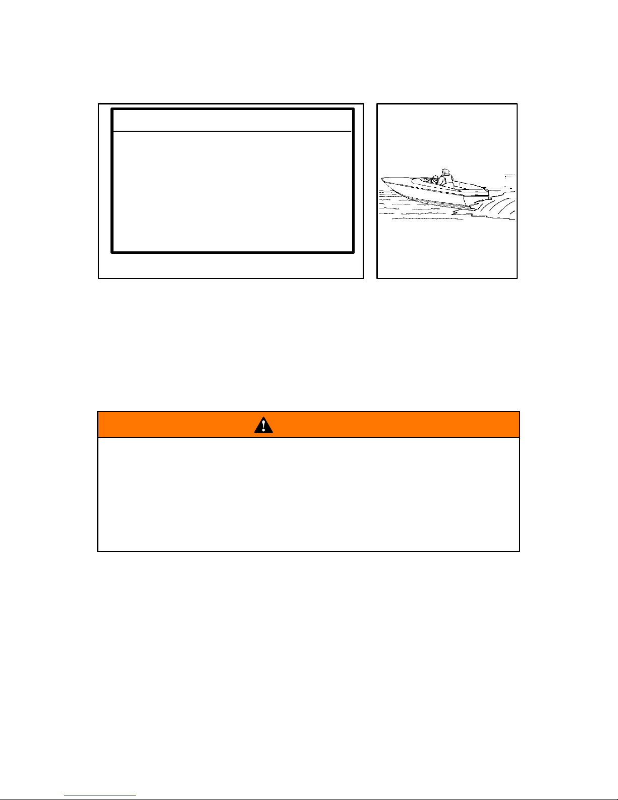
WARNING
Overpowering a Boat Can Cause:
• Serious injury, death, or boat damage.
• Loss of Boat Control.
• Flotation Characteristics of Boat to be Altered from Placing
Too Much Weight on Transom.
• Boat to Break Apart, Particularly Around the Transom Area.
High-Speed and High-Performance Boat Operation
2 If you are not familiar with high-performance boat operation we
recommend that you first request an orientation/demonstration
ride with your dealer or an operator experienced with your boat/
sterndrive combination. Refer to the “Guide to Hi-Performance
Boat Operation” booklet (P/N 90-849250R1) included in your literature packet.
Page 23
19500 EFI Bravo
ob
GENERAL INFORMATION
gob8
obg6
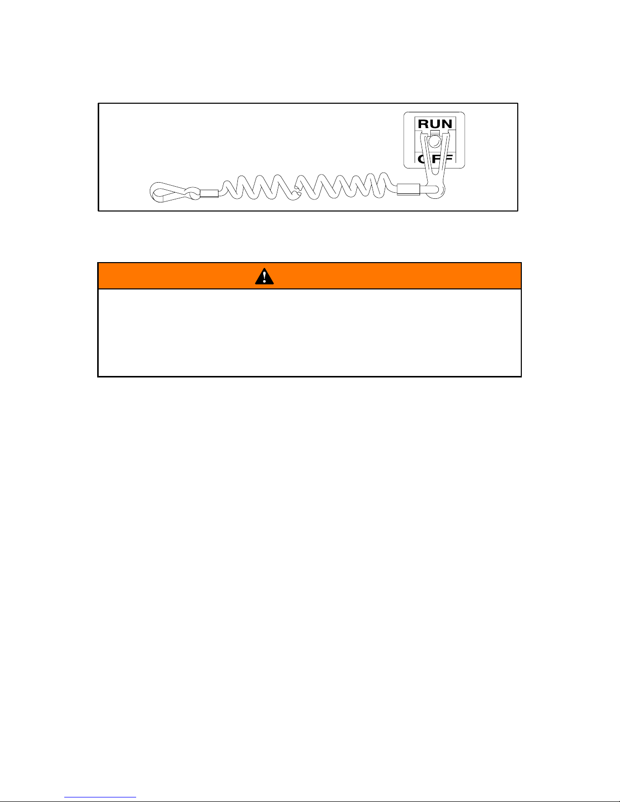
Lanyard Stop Switch
WARNING
Should the operator fall out of the boat, the possibility of serious injury or death from being run over by the boat can be
greatly reduced by stopping the engine immediately. Always
properly connect both ends of the stop switch lanyard to the
stop switch and the operator.
1 The purpose of a lanyard stop switch is to turn off the engine
when the operator moves far enough away from the operator’s
position (as in accidental ejection from the operator’s position) to
activate the switch. A lanyard stop switch can be installed as an
accessory – generally on the dashboard or side adjacent to the
operator’s position.
2 While activation of the lanyard stop switch will stop the engine im-
mediately, a boat will continue to coast for some distance depending upon the velocity and degree of any turn at shut-down.
However, the boat will not complete a full circle. While the boat
is coasting, it can cause injury to anyone in the boat’s path as s eriously as the boat would when under power.
(continued on next page)
Page 24
20 500 EFI Bravo
ob
GENERAL INFORMATION
Lanyard Stop Switch (Continued)
WARNING
Avoid serious injury or death from deceleration forces resulting from in accidental stop switch activation. The boat operator should never leave the operator’s station without first disconnecting the stop switch lanyard cord from themself.
Accidental or unintended activation of the Lanyard Stop Switch during normal operation is a possibility and could cause any, or a ll , of t he
following potentially hazardous situations:
3 Occupants could be thrown forward due to unexpected loss of
forward motion – a particular concern for passengers in the front
of the boat who could be ejected over the bow and possibly struck
by the gear case or propeller.
4 Loss of power and directional control in heavy seas, strong cur-
rent or high winds.
5 Loss of control when docking.
CA19
Trailering Boat
Boat can be trailered with drive unit in “up” or “down” position.
Adequate road clearance is required between road and gear housing
skeg when trailering with drive unit in “down” position.
If adequate road clearance is a problem, place drive unit in full trailer
position and support with an optional trailer kit which is available from
your Authorized MerCruiser Dealer.
Page 25
21500 EFI Bravo
GENERAL INFORMATION
gob3
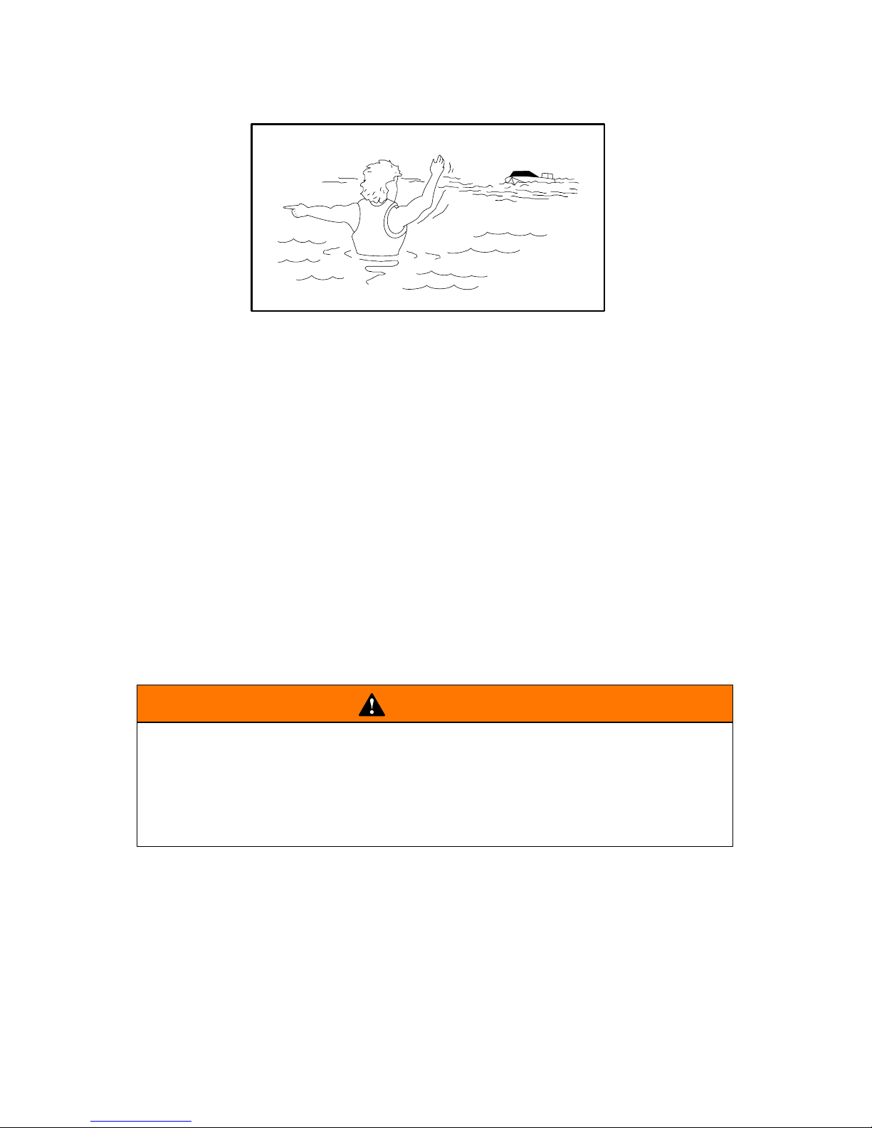
Protecting People In The Water
WHILE YOU ARE CRUISING
It is very difficult for a person in the water to take quick action to avoid
a boat heading in their direction even at slow speed.
Always slow down and exercise extreme caution any time you are
boating in an area where there might be people in the water.
Whenever a boat is moving (even coasting) even with the drive unit
in neutral position, there is sufficient force by the water to rotate the
propeller. This neutral propeller rotation can cause serious injury.
WHILE BOAT IS STATIONARY
Shift the drive unit into neutral and shut off the engine before allowing
people to swim or be in the water near your boat.
WARNING
Stop your engine immediately whenever anyone in the water
is near your boat. Serious injury to the person in the water is
likely if contacted by a rotating propeller, a moving boat, a
moving gear case, or any solid device rigidly attached to a
moving boat or gear case.
Page 26
22 500 EFI Bravo
GENERAL INFORMATION
Courtesy of ABYC
1
2
3
4
5
Page 27
23500 EFI Bravo
GENERAL INFORMATION
Carbon Monoxide Risk
WARNING
Avoid the combination of a running engine and poor ventilation. Prolonged exposure to carbon monoxide in sufficient
concentration can lead to unconsciousness, brain damage, or
death.
Carbon monoxide is a deadly gas that is odorless, colorless and
tasteless and is present in the exhaust fumes of all internal
combustion engines.
Early symptoms of carbon monoxide poisoning which should not be
confused with seasickness or intoxication, include headache, dizziness, drowsiness, and nausea.
INSUFFICIENT FRESH AIR FLOW
Under certain conditions, enclosed or canvas enclosed cabins or
cockpits with insufficient ventilation may draw in carbon monoxide.
Install one or more carbon monoxide detectors in your boat.
Although rare, on a very calm day, swimmers and passengers in an
open stationary boat with a running engine, or near a running engine
may be exposed to a hazardous level of carbon monoxide.
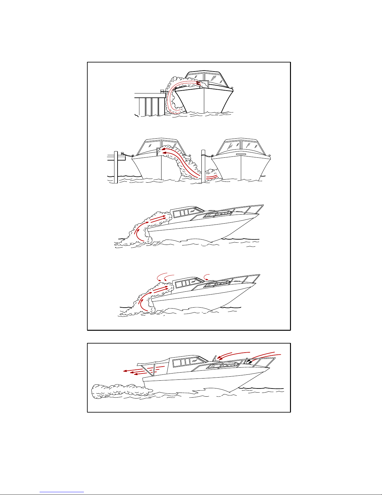
Insufficient Air Flow Could Occur If:
While boat is stationary
1 Boat moored in a confined space with the engine running.
2 Boat is moored close to another boat with its engine running.
While boat is moving
3 Running the boat with the trim angle of the bow too high.
4 Running the boat with no forward hatches open (station wagon
effect).
SUFFICIENT FRESH AIR FLOW
5 Example of desired air flow through the boat.
Ventilate passenger area, open side curtains, or forward hatches to
remove carbon monoxide fumes.
Page 28
24 500 EFI Bravo
ob
GENERAL INFORMATION
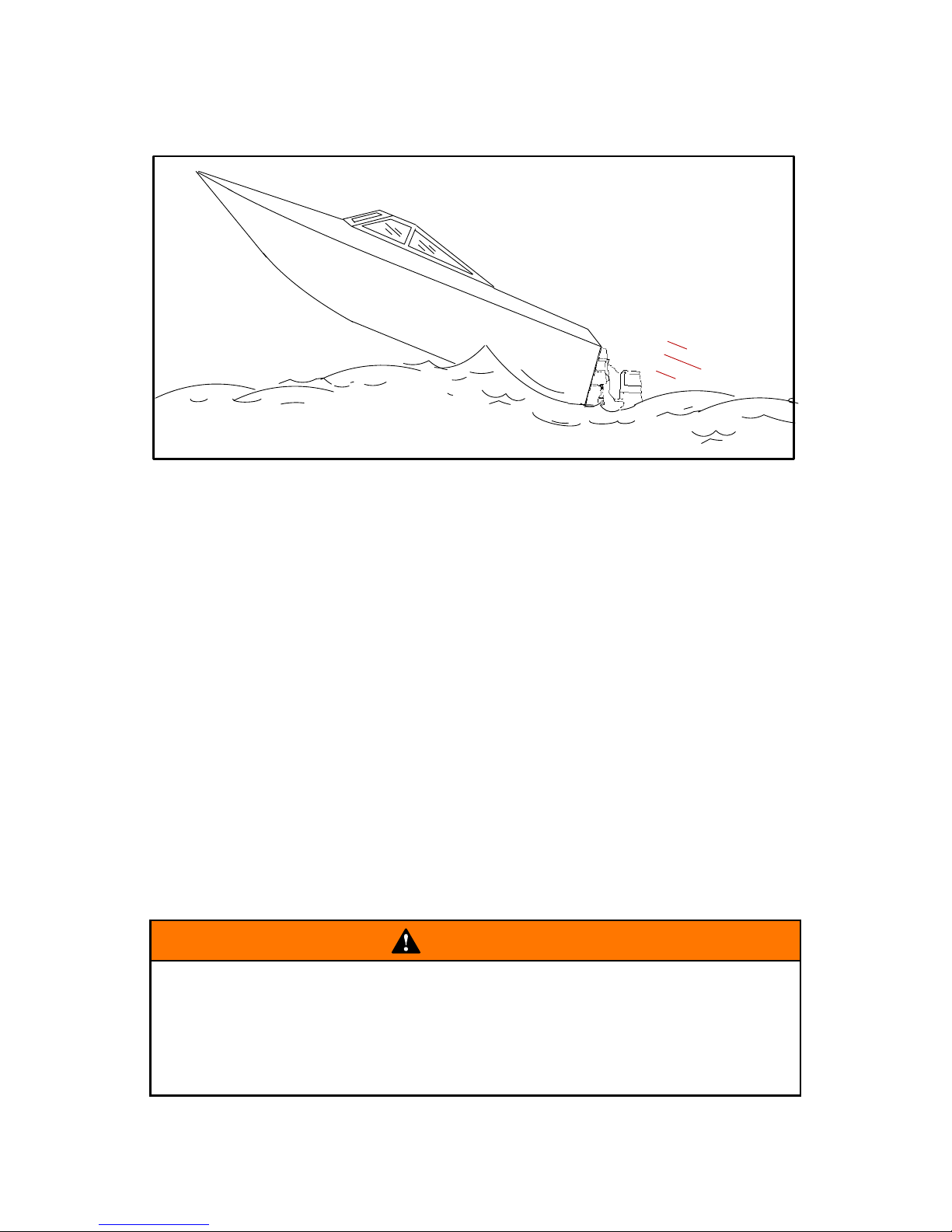
Wave And Wake Jumping
Operating recreational boats over waves and wakes is a natural part
of boating. However, when this activity is done with speed to force the
boat hull partially or completely out of the water, certain hazards
arise, particularly when the boat re-enters the water.
The primary concern is the boat changing direction while in the midst
of the jump. In such case the landing may cause the boat to violently
veer in a new direction. Such a sharp change in direction or turn can
cause occupants to be thrown out of their seats or out of the boat.
There is another less common hazardous result from allowing your
boat to launch off a wave or wake. If the bow of your boat pitches
down far enough while airborne, upon water contact it may penetrate
under the water surface and “submarine” for an instant. This will bring
the boat nearly to a stop in an instant and can send the occupants
flying forward. The boat may also steer sharply to one side.
WARNING
Avoid serious injury or death from being thrown within or out
of a boat when it lands after jumping a wave or wake. Avoid
wave or wake jumping whenever possible. Instruct all occupants that if a wake or wave jump occurs, get low and hang on
to any boat hand hold.
Page 29
25500 EFI Bravo
ob
GENERAL INFORMATION
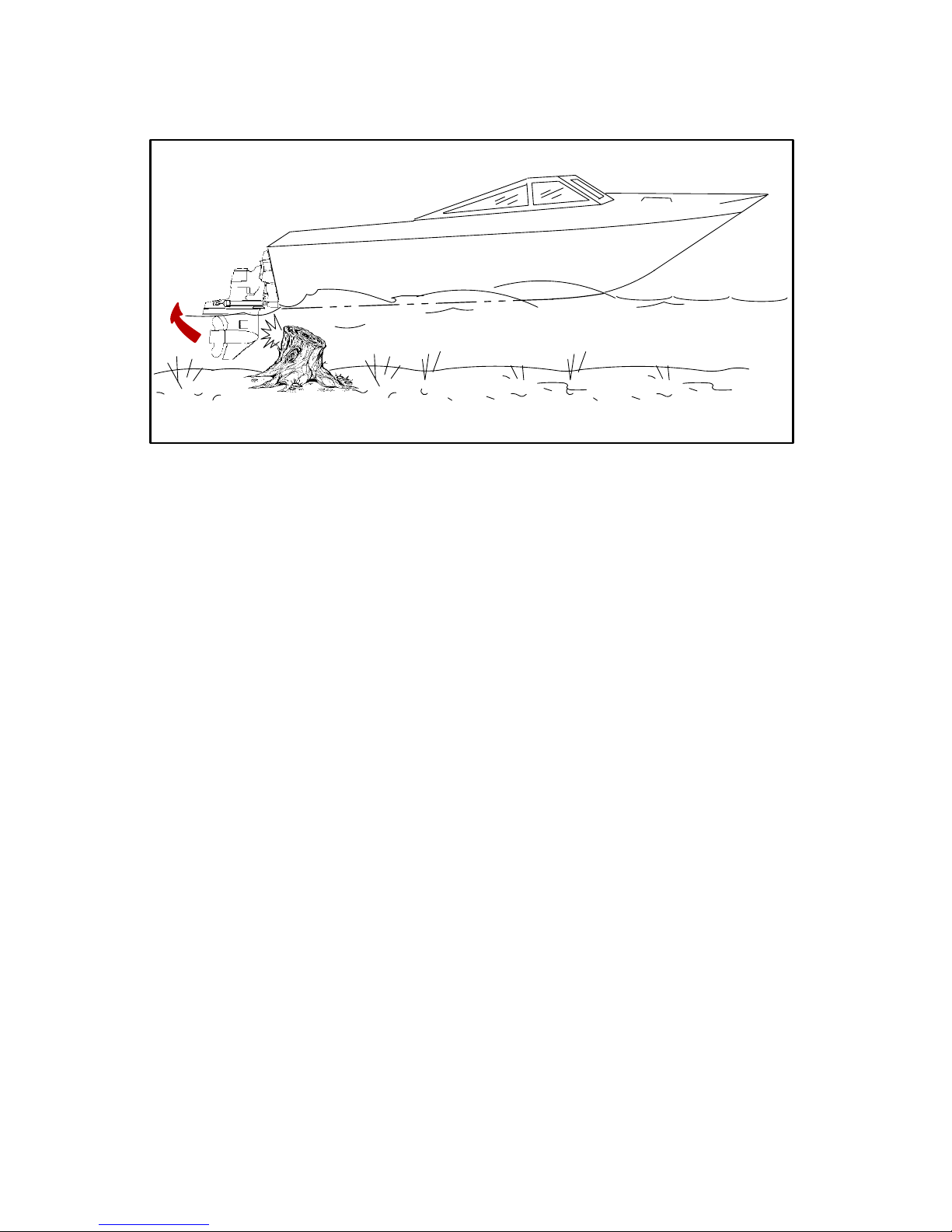
Impact With Underwater Hazards
Reduce speed and proceed with caution whenever you’re driving a
boat in shallow water areas or in areas where the waters are suspected of having underwater obstacles that could be struck by the
sterndrive or the boat bottom. The Power Trim hydraulic system is
designed to provide some impact protection for the drive unit if a submerged object is struck while boat is moving forward. There is no impact protection in REVERSE. The hydraulic system will cushion the
kickup of the drive unit as it clears the object, reducing damage to
unit. After drive unit has cleared object, the drive will return to the
original operating position, preventing loss of steering control and
engine over-speed. The most important thing you can do to help
reduce injury or impact damage from striking a floating or
underwater object is control the boat speed. When driving in
waters known to have floating or underwater obstacles, boat
speed should be kept to a minimum planing speed (15 to 25
mph).
IMPORTANT: The impact protection system cannot be
designed to ensure total protection from impact damage under
all conditions.
(continued on next page)
Page 30
26 500 EFI Bravo
GENERAL INFORMATION
Impact With Underwater Hazards (cont.)
Striking a floating/underwater object may result in an infinite number
of situations. Some of these situations could result in the following:
• The boat could move suddenly in a new direction. Such a sharp
change in direction or turn can cause occupants to be thrown out
of their seats or out of the boat.
• A rapid reduction in speed. This will cause occupants to be thrown
forward, even out of the boat.
• Impact damage to the sterndrive and/or boat.
After striking a submerged object, stop engine as soon as possible
and inspect the sterndrive unit for any broken or loose parts. If damage is present or suspected, the power package should be taken to
an authorized dealer for a thorough inspection and necessary repair.
The boat should also be checked for any hull fractures, transom fractures, water leaks.
Operating a damaged sterndrive could cause additional damage to
other parts of the power package, or could affect control of the boat.
If continued running is necessary, do so at greatly reduced speeds.
WARNING
Avoid serious injury or death from loss of boat control. Continued boating with major impact damage can result in sudden
component failure with or without subsequent impacts, Have
the power package thoroughly inspected and any necessary
repairs made.
Page 31

27500 EFI Bravo
GENERAL INFORMATION
CA802
1
2
Operating In Shallow Water
CAUTION
Serious engine damage could occur by failing to follow these
instructions. Sand, silt or mud could be sucked into the water
inlets restricting or shutting off the water supply to the engine.
1 Low Water Inlet Gear Cases: Extreme care should be exercised
when operating a boat equipped with only low water inlets while
maneuvering in sh a l l o w w a t e r. Due to a small amount of total water inlet area, there is high suction at the water inlets. These inlets
will easily clog with bottom contact and are susceptible to clogging when operated in shallow or weedy water.
2 Dual W ater Inlet Gear Cases: The design of the dual water inlet
gear case reduces the risk of restricting or shutting off the water
supply to the engine, but caution should still be used when operating in shallow weedy water.
Clearing a Dual Water Inlet Gear Case
• Idle the boat out to deep water.
• Bring the boat up on plane but operate at a moderate speed
until the engine temperature and block water pressure returns to normal. Engine block pressure at the gauge can still
be low if the line to the gauge is clogged.
Page 32

28 500 EFI Bravo
GENERAL INFORMATION
Safe Boating Suggestions
In order to safely enjoy the waterways, familiarize yourself with local
and other governmental boating regulations and restrictions, and
consider the following suggestions.
• Know and obey all nautical rules and laws of the waterways.
Boat operators should complete a boating safety course. Courses
are offered in the U.S.A. by (1) The US Coast Guard Auxiliary, (2)
The Power Squadron, (3) The Red Cross and (4) your state or
provincial boating law enforcement agency. Inquiries may be
made to the Boating Hotline, 1-800-368-5647 or the Boat US
Foundation information number 1-800-336-BOAT.
We strongly recommend that all powerboat operators attend one of
these courses.
You should also review the NMMA Sources of Waterway Information
booklet. It lists regional sources of safety, cruising and local
navigation and is available at no charge by writing to:
Sources of Waterway Information
National Marine Manufacturers Association
410 N. Michigan Avenue
Chicago, IL 60611 U.S.A.
• Perform safety checks and required maintenance. Follow a
regular schedule and ensure that all repairs are properly made.
• Check safety equipment on board. Here are suggestions of the
types of safety equipment to carry when boating:
a. Approved fire extinguisher(s); paddle or oar.
b. Signal devices: flashlight, rockets or flares, flag and whistle
or horn.
c. Spare propeller, thrust hubs and an appropriate wrench.
d. Tools for necessary minor repairs; first aid kit and book.
e. Anchor, extra anchor line; water-proof storage containers.
f. Manual bilge pump and extra drain plugs; compass and map
or chart of area.
g. Spare operating equipment; batteries, bulbs, fuses, etc.
h. Transistor radio and drinking water.
(continued on next page)
Page 33

29500 EFI Bravo
GENERAL INFORMATION
Safe Boating Suggestions (Continued)
• Know signs of weather change and avoid foul weather and
rough-sea boating.
• Tell someone where you are going and when you expect to
return.
• Passenger boarding. Stop the engine whenever passengers are
boarding, unloading or are near the back (stern) of the boat. Just
shifting the drive unit into neutral is not sufficient.
• Use personal flotation devices. Federal Law requires that there
be a U. S. Coast Guard approved, wearable-type life jacket (personal flotation device), correctly sized and readily accessible for
every person on board, plus a throwable cushion or ring. We
strongly advise that everyone wear a life jacket at all times while
in the boat.
• Prepare other boat operators. Instruct at least one person on
board in the basics of starting and operating the engine and boat
handling in case the driver becomes disabled or falls overboard.
• Do not overload your boat. Most boats are rated and certified
for maximum load (weight) capacities (refer to your boat capacity
plate). When in doubt, contact your dealer or the boats manufacturer. Know your boat’s operating and loading limitations.
• Make sure everyone in the boat is properly seated. Don’t allow
anyone to sit or ride on any part of the boat that was not intended
for such use. This includes backs of seats, gunwales, transom,
bow, decks, raised fishing seats, any rotating fishing seat; anywhere that sudden unexpected acceleration, sudden stopping,
unexpected loss of boat control or sudden boat movement could
cause a person to be thrown overboard or into the boat.
• Never be under the influence of alcohol or drugs while boat-
ing (it is the law). They impair your judgment and greatly reduce
your ability to react quickly.
(continued on next page)
Page 34

30 500 EFI Bravo
GENERAL INFORMATION
Safe Boating Suggestions (Continued)
• Know your boating area and avoid hazardous locations.
• Be alert. The operator of the boat is responsible by law to “main-
tain a proper lookout by sight (and hearing).” The operator must
have an unobstructed view particularly to the front. No passengers, load, or fishing seats should block the operators view when
operating the boat above idle or planing transition speed. Watch
“the other guy,” the water and your wake.
• Never drive your boat directly behind a water skier in case
the skier falls. As an example, your boat traveling at 25 miles per
hour (40 km/h) in 5 seconds will overtake a fallen skier who was
200 feet in front of you.
• Watch fallen skiers. When using your boat for water skiing or
similar activities, always keep a fallen or down skier on the operator’s side of the boat while returning to attend the skier . The operator should always have the down skier in sight and never back up
to the skier or anyone in the water.
• Report accidents. Boat operators are required by law to file a
Boating Accident Report with their state boating law enforcement
agency when their boat is involved in certain boating accidents.
A boating accident must be reported if (1) there is loss of life or
probable loss of life, (2) there is personal injury requiring medical
treatment beyond first aid, (3) there is damage to boats or other
property where the damage value exceeds $500.00 or (4) there
is complete loss of the boat. Seek further assistance from local
law enforcement.
CA21
Stolen Power Package
If your power package is stolen, immediately advise the local
authorities and Mercury Marine of the model and serial number(s)
and to whom the recovery is to be reported. This “Stolen Motor”
information is placed into a file at Mercury Marine to aid authorities
and dealers in recovery of stolen motors.
Page 35

31500 EFI Bravo
ca261hp
SPECIFICATIONS
Fuel Requirements
WARNING
FIRE AND EXPLOSION HAZARD: Fuel leakage from any part
of fuel system can be a fire and explosion hazard which can
cause serious bodily injury or death. Careful periodic inspection of entire fuel system is mandatory, particularly after storage. All fuel components including fuel tanks, whether plastic
metal or fiberglass, fuel lines, fittings, fuel filters and carburetors/fuel injection components should be inspected for leakage, softening, hardening, swelling or corrosion. Any sign of
leakage or deterioration requires replacement before further
engine operation.
CAUTION
Use of improper gasoline can damage your engine seriously.
Engine damage resulting from use of improper gasoline is
considered misuse of engine, and damage caused thereby
will not be covered under the limited warranty.
OCTANE REQUIREMENTS FOR YOUR ENGINE:
(UNITED STATES AND CANADA)
FUEL TYPE MINIMUM POSTED OCTANE
Unleaded regular or premium
1
(R+M)÷2=87 or RON*=92
*Research Octane Number
WHEN UNLEADED FUEL IS NOT AVAILABLE USE:
(OUTSIDE THE UNITED STATES AND CANADA)
FUEL TYPE
MINIMUM POSTED OCTANE
Leaded regular (R+M)÷2=89 or RON*=94
*Research Octane Number
1
The use of premium unleaded fuels with octane ratings higher than
(R+M)÷2=87 are acceptable to use but will not give any increase in
performance or durability.
(continued on next page)
Page 36

32 500 EFI Bravo
SPECIFICATIONS
USING REFORMULATED (OXYGENATED) GASOLINES (USA
ONLY)
This type of gasoline is required in certain areas of the US. The two
types of “oxygenates” used in these fuels are alcohol (Ethanol) or
Ether (MTBE or ETBE). If Ethanol is the “oxygenate” that is used in
the gasoline in your area, refer to “Gasolines Containing Alcohol”
also.
These “Reformulated Gasolines” are acceptable for use in your MerCruiser engine.
CA277hp
GASOLINES CONTAINING ALCOHOL
If the gasoline in your area contains either “methanol” (methyl
alcohol) or “ethanol” (ethyl alcohol), you should be aware of certain
adverse effects that can occur. These adverse effects are more
severe with “methanol”. Increasing the percentage of alcohol in the
fuel can also worsen these adverse effects.
Some of these adverse ef fects are caused because the alcohol in the
gasoline can absorb moisture from the air, resulting in a separation
of the water/alcohol from the gasoline in the fuel tank.
The fuel system components on your MerCruiser engine will
withstand up t o 10% alcohol content in the gasoline. W e do not know
what percentage your boat’s fuel system will withstand. Contact your
boat manufacturer for specific recommendations on the boats fuel
system components (fuel tanks, fuel lines, and fittings).
(continued on next page)
Page 37

33500 EFI Bravo
SPECIFICATIONS
GASOLINE CONTAINING ALCOHOL MAY INCREASE:
• Corrosion of metal parts.
• Deterioration of rubber or plastic parts.
• Fuel permeation through rubber fuel lines.
• Starting and operating difficulties and decrease in performance.
Because of possible adverse effects of alcohol in gasoline, it is
recommended that only alcohol-free gasoline be used where
possible. If only fuel containing alcohol is available, or if the pres-
ence of alcohol is unknown, increased inspection frequency for leaks
and abnormalities is required.
IMPORTANT: When operating a MerCruiser engine on gasoline
containing alcohol, storage of gasoline in the fuel tank for long
periods should be avoided. Long periods of storage, common
to boats, create unique problems. In cars alcohol-blend fuels
normally are consumed before they can absorb enough moisture to cause trouble, but boats often sit idle long enough for
phase separation to take place. In addition, internal corrosion
may take place during storage if alcohol has washed protective
oil films from internal components.
Page 38

34 500 EFI Bravo
SPECIFICATIONS
Crankcase Oil
OIL RECOMMENDATIONS
PREFERRED OILS
API
CLASSIFICATION
Quicksilver 4-Cycle Marine Engine Oil
(25W-40)
SH, SG, CF/CF-2
Premium grade multi-viscosity 20W-50 automotive oil
SH, SG, CF/CF-2
OTHER RECOMMENDATIONS IF PREFERRED OILS ARE
NOT AVAILABLE
Premium multi-viscosity 20W-40 automotive oil
SH, SG, CF/CF-2
Straight weight detergent automotive oil of
correct viscosity (See Chart Below)
SH, SG, CF/CF-2
Oil filter should always be changed with oil
IMPORTANT OIL PRACTICES
Do Not Use
• Non-detergent oils
• Oils containing solid additives
• Multi-viscosity oils other than the ones recommended
• Low quality oils
Do Not Mix
• Straight weight and multi-viscosity oils
• Different brands of oils, straight weight or multi-viscosity
• Different weights of straight weight or different weights of multi-
viscosity oils.
Page 39

35500 EFI Bravo
SPECIFICATIONS
Crankcase Oil (con’t)
TEMPERATURE/OIL VISCOSITY CHART
Straight Weight
SH, SG,
CF/CF-2
Multi-viscosity
Oils
-20 0 +20 +40 +60 +80 +100
°
F
C
°
Oils
30
40
SH, SG,
CF/CF-2
-20-30 -10 +200 +30 +40+10
Quicksilver 25W 40
20W 50
Capacities
MODEL 500 EFI
Crankcase Oil Capacity w/New Filter
1
8 US qts (7.6 L)
Bravo XR/XZ - Drive
Unit Oil Capacity (w/
Monitor)
2.8 US qts (2.65 L)
Bravo III - Drive Unit
Oil Capacity (w/Monitor)
3 US qts (2.8 L)
Seawater Cooling
System
2
20 US qts (18.9 L)
1
Always use dipstick to determine exact quantity of oil required.
2
Seawater Cooling System capacity information is for winterization use only.
Page 40

36 500 EFI Bravo
SPECIFICATIONS
Engine Specifications
NOTE: Where applicable, specifications are derived at sea level.
MODEL
500 EFI
Displacement
cid/L
502 (8.2)
Propshaft
Horsepower
470
Propshaft
Kilowatts
350
Bore 4.47 in. (113.5 mm)
Stroke 4.00 in. (101.6 mm)
Compression Ratio 8.75:1
Compression
Pressure
175 psi (1207 kPa)
Maximum rpm @
WOT
1
4800-5200
Idle rpm in or out of
Gear
750 Minimum
Fuel Pump
Pressure (Mechanical Fuel Pump
3-7 psi (21-48 kPa)
Fuel pump pressure
(@ Fuel Rail)
IDLE 39 psi. (269 kPa)
W.O.T 41 psi. (282 kPa)
(continued on next page)
Page 41

37500 EFI Bravo
SPECIFICATIONS
Engine Specifications (cont.)
MODEL 500 EFI
Oil Pressure
@ Idle rpm (Hot)
30 psi (207 kPa)
Min. Oil Pressure
@ W.O.T.
45 psi Min. (310 kPa)
Engine Oil Temp.
@ 5200 rpm
170°-180°F (77° –82°C)
Thermostat 140°F (61°C)
Engine Water Pres-
sure @ 4800–5200
rpm
20 psi min.-30 psi max. measured at the
lower block drain position
1
Engines are equipped with an ignition system that have a built-in 5400 rpm rev
limiter. Engine is performing normally if it will not exceed this rpm.
Tune Up Specifications
MODEL 500 EFI
Spark Plug Type
AC-MR43T, NGK BR6FS, P/N 33-59571 or
Champion RV8C
Spark Plug Gap .035 in. (0.9 mm)
Timing @ Idle
rpm
8° BTDC (See Note)
Firing Order 1-8-4-3-6-5-7-2
Serpentine Belt
Tension (Note 2)
New 120 lbs. (530 N)
Used 80 lbs (350 N)
Note 1: A special procedure must be followed to check or adjust timing. Consult your
Authorized MerCruiser Dealer before attempting this procedure.
Note 2: Special belt tension tool required.
Page 42

38 500 EFI Bravo
SPECIFICATIONS
Tune Up Specifications (cont.)
MODEL 500 EFI
Electrical System 12-Volt Negative (-) Ground
Alternator 50 Amps
Valve Lash 1 turn down from zero lash
Recommended
Battery Rating
Minimum
550 CCA or 700 mca or 120 Amp/Hrs
FRONT
LH ROTATION
Firing Order
1-8-4-3-6-5-7-2
Page 43

39500 EFI Bravo
OPERATION
Engine Break-in
CAUTION
Severe damage to the engine can result by not complying with
the Engine Break-in Procedure.
5 HR. BREAK-IN PROCEDURE
• Allow engine to warm-up for 30 - 60 seconds.
• Do not exceed 3/4 throttle.
• Avoid full throttle acceleration from IDLE speed.
• Always vary throttle setting.
• Run engine the majority of time between 3000 - 4500 rpm.
• Frequently check crankcase oil level. Add oil if needed. It is nor-
mal for oil consumption to be high during break-in period.
CA211hp
After Break-In Period
To help extend the life of your MerCruiser power package, the
following recommendations should be considered:
AFTER 5 HR. BREAK-IN
• Use a propeller that allows the engine to operate at or near the
top of the maximum rpm range (See “Specifications” section)
when at full throttle with a normal boat load.
• Operation at 3/4 throttle setting or lower is recommended. Re-
frain from prolonged operation at maximum (full throttle) rpm.
• Do not operate at full throttle until engine reaches normal oper-
ating temperature.
• Follow the maintenance schedule in this manual.
Page 44

40 500 EFI Bravo
CA26
OPERATION
70514
70515
70516
70523
70517
70522
70518
70521
70519
1
2
3
7
5
6
8
9
10
4
70518
100 300
Page 45

41500 EFI Bravo
OPERATION
Instrumentation
The following is a brief explanation of instrumentation typically found
on some boats. The owner/operator should be familiar with all instruments and their functions on the boat.
1 Speedometer - indicates boat speed.
2 Tachometer - indicates engine rpm.
3 Oil Pressure Gauge - indicates engine oil pressure.
4 Oil Temperature Gauge - indicates engine oil operating tempera-
ture.
5 Water Temperature Gauge - indicates engine operating temper-
ature.
6 Fuel Gauge - indicates fuel tank volume.
7 Battery Meter - indicates battery voltage.
8 Hour Meter - records engine running time.
9 Bilge Blower Switch - must be operated for five minutes before
starting engine to ventilate bilge.
10 Ignition Switch - allows operator to start and stop engine.
Page 46

42 500 EFI Bravo
OPERATION
CB218
70516
1
2
70518
70517
4
3
Page 47

43500 EFI Bravo
OPERATION
Audio Warning System
Your MerCruiser power package may be equipped with an Audio
Warning System.
NOTE: Testing the System: The buzzer will sound when the ignition
switch is turned to the RUN position, prior to cranking the engine.
Once the engine starts, the buzzer should stop.
CAUTION
Avoid engine damage. Do not operate engine once a continuous buzzer has sounded EXCEPT TO AVOID A HAZARDOUS
SITUATION. The Audio Warning System will not protect the
engine from damage. It is designed to warn the operator that
a problem has occurred.
When the buzzer sounds with the engine running, stop engine
immediately. Investigate cause and correct it, if possible. If cause
cannot be determined, consult your Authorized MerCruiser Dealer.
The audio warning system buzzer will sound continuously if any of
the following occur:
1 Insufficient Oil Pressure.
2 Excessive Engine Temperature.
3 Insufficient Drive Lubricant.
4 Low Voltage (At or below 10V).
The audio warning system will beep steadily if the ECM detects a
fault code from one of the engine sensors. A fault code will be set in
the ECM.
1 The beeping warning can be stopped by turning the engine off.
If beeping continues on restart, a fault code was detected again.
Correct problem before further operation.
2 On restart, if the beeping has stopped, a fault code has been set
in the ECM and will need to be diagnosed and cleared by an Authorized MerCruiser Dealer.
Page 48

44 500 EFI Bravo
OPERATION
70525
70528
70526
2
4
3
1
40671
6
5
Page 49

45500 EFI Bravo
OPERATION
Electrical System Overload Protection
If an electrical overload occurs, a fuse will blow or the circuit breaker
will trip open. The cause must be found and corrected before replacing fuse or resetting circuit breaker.
1 A circuit breaker provides protection for engine wiring harness
and instrumentation power lead. Reset by pushing RESET button IN.
In an emergency , when engine must be operated and cause for high
current draw cannot be located and corrected, perform the following:
• Turn OFF or disconnect all accessories connected to engine and
instrumentation wiring.
• Reset circuit breaker.
• If breaker remains open, electrical overload has not been elimi-
nated.
• Further checks must be made on electrical system.
2 A 20 amp fuse may be located in ignition switch “I” terminal lead
to protect electrical system. Check for blown fuse if key is turned
to START and nothing happens (and circuit breaker is not
tripped).
3 The Power Trim System is protected from overload by 110 amp
fuse and a 20 amp in-line fuse on Power Trim pump.
NOTE: Dual Power Trim Control Models-Refer to wiring diagrams
for fuse location.
4 The Quicksilver MerCathode System has a 20 amp in-line fuse
in the wire which connects to positive (+) terminal on controller.
If fuse is blown, system will not operate and a loss of corrosion
protection will result.
5 A 90 amp. fuse is located on the starter.
6 Three fuses are located at the upper rear of the engine.
• 15 amp. = Fuel Pump
• 15 amp. = Electronic Control Module (ECM), Data Link Con-
nector (DLC) / Battery
• 10 amp. = ECM / Ignition / Injectors / Battery
Page 50

46 500 EFI Bravo
OPERATION
CB181
4
5
3
1
7
6
2
Page 51

47500 EFI Bravo
OPERATION
CB182
Remote Controls (Panel Mounted)
Your boat may be equipped with one of many Quicksilver remote
controls available. All controls feature an integral safety switch that
allows starting engine in NEUTRAL only. Also, all controls may not
have all features shown. If boat is equipped with a remote control
other than shown, consult your dealer for a description and/or
demonstration of the control.
1 Neutral Lock Bar - Prevents accidental shift and throttle
engagement. Neutral lock bar must be pulled “Up” to move the
control handle out of neutral.
2 Throttle Only Button - Allows throttle advancement without
shifting the engine. This is done by disengaging the shift mechanism from the control handle. The throttle only button can be
depressed only when the remote control handle is in the “Neutral”
position, and should only be used to assist in starting the engine.
3 Power Trim Switch - See “Power Trim” for detailed power trim
operating procedures.
4 Trailer Switch - (Not used with Bravo Heavy Duty Transoms)
See “Power Trim” for detailed trailer switch operation.
5 Lanyard Stop Switch - Turns the ignition “Off”. See “Lanyard
Stop Switch” at the front of this manual for operation and safety
warning on the use of this switch.
6 Control Handle Tension Adjustment Screw - This screw can
be adjusted to “Increase” or “Decrease” the tension on the control
handle. This will help prevent “Creep” of the remote control handle. Turn screw “Clockwise” to increase tension and “Counterclockwise” to decrease tension. Adjust to tension desired.
7 Control Handle - Operation of the shift and throttle are controlled
by the movement of the control handle. “Push” the control handle
forward from “Neutral” with a quick firm motion to the first detent
for “Forward” gear. Continue pushing forward to increase speed.
Pull the control handle back from “Neutral” with a quick firm
motion to the first detent for “Reverse” gear. Continue pulling
back to increase speed.
Page 52

48 500 EFI Bravo
OPERATION
CB183
6
5
5
2
2
1
4
4
6
1
3
3
Page 53

49500 EFI Bravo
OPERATION
CB184
Remote Controls (Console Mounted)
1 Control Handle(s) - Operation of the shift and throttle are con-
trolled by the movement of the control handle. “Push” the control
handle forward from “Neutral” with a quick firm motion to the first
detent for “Forward” gear . Continue pushing forward to increase
speed. Pull the control handle back from “Neutral” with a quick
firm motion to the first detent for “Reverse” gear. Continue pulling
back to increase speed.
2 Throttle Only Button - Allows engine throttle advancement
without shifting the engine. This is done by disengaging the shift
mechanism from the control handle. The throttle only button can
be depressed only when the remote control handle is in the “Neutral” position, and should only be used to assist in starting the
engine.
3 Control Handle Tension Adjustment Screw - This screw can
be adjusted to “Increase” or “Decrease” the tension on the control
handle (cover must be removed to adjust). This will help prevent
“Creep” of the remote control handle. Turn screw “Clockwise” to
increase tension and “Counterclockwise” to decrease tension.
Adjust to tension desired.
4 Power Trim Switch - See “Power Trim” section for detailed
power trim operating procedures.
5 Trailer Switch - (Not used with Bravo Heavy Duty Transoms)
See “Power Trim” for detailed trailer switch operation.
6 Power Trim Adjustment Switch’s (Used on Three Button
Trim Control Only) - See “Power Trim” section for detailed
power trim operating procedures.
Page 54

50 500 EFI Bravo
OPERATION
1-3
1
2
3
Page 55

51500 EFI Bravo
OPERATION
CB184
Remote Controls (Console Mounted Zero Effort)
1 Throttle Control Lever(s) - Operation of the throttle is controlled
by the movement of the longer control lever(s). “Pushing” the
control lever forward increases engine speed. Detentes are used
to give the movement of the lever a “notched” precise feel. The
detentes also help to hold the lever at the desired engine rpm to
reduce operator fatigue.
CAUTION
Never shift unit into or out of gear unless the engine is at idle
rpm.
2 Shift Control Lever(s) - Shifting is controlled by the shorter con-
trol lever ( s ) . This co n t r o l s h i f t s u n i t i nto gear with full lever movement. Move lever forward to engage FORWARD gear. Move lever backward to engage REVERSE gear . Lever in center position
shifts to NEUTRAL. Shifting should occur only with the engine at
idle speed. Always move to the desired gear position with a quick,
firm motion. The control handle should be adjusted by your dealer to engage forward, reverse and neutral when the lever is at the
appropriate detent.
3 Power Trim Switch - See “Power Trim” section for detailed
power trim operating procedures.
Page 56

52 500 EFI Bravo
OPERATION
CA34
1
2
°
3 - 5
Page 57

53500 EFI Bravo
OPERATION
Power Trim
Power Trim allows the operator to adjust the drive angle, while
underway, to provide the ideal boat angle for varying load and water
conditions.
CAUTION
Engine must maintain a minimum of 20 psi of water pressure
and should not exceed 30 psi maximum at 4800 to 5200 RPM
as measured at the lower block drain position (either side of
the block).
IMPORTANT: In order to significantly raise the strength of the
Hi-Performance heavy duty gimbal ring, the trim limit and electric trim indicator sending unit mounting position has been
eliminated. Having no trim limit switch permits the operator to
trim the drive to any position at any throttle setting.
CAUTION
Use extreme caution when operating with drive unit raised.
Severe damage to the drive unit may result if unit is raised beyond the gimbal ring support flanges at engine speeds above
1200 rpm. It is recommended that Bravo heavy duty gimbal
rings use manual indicators to help keep the operator aware
of the drive positioning.
1 In most cases, best overall performance is obtained with the
drive unit adjusted so the boat bottom will run at a 3° to 5° angle
to the water.
2 Trimming Drive Unit UP/OUT Can:
• Generally increase top speed.
• Increase clearance over submerged objects or a shallow bottom.
• Cause boat to accelerate and plane off slower.
• In excess, cause boat porpoising” (bouncing) or propeller ventila-
tion.
• Cause engine overheating if trimmed UP/OUT to a point where
any cooling water intake holes are above the water line.
(continued on next page)
Page 58

54 500 EFI Bravo
OPERATION
3
Power Trim (cont.)
3 Trimming Drive Unit DOWN/IN Can:
• Help the boat accelerate and plane off quicker.
• Generally improve the ride in choppy water.
• In most cases, reduce boat speed.
• If in excess, lower the bow of some boats to a point at which they
begin to plow with their bow in the water while on plane. This can
result in an unexpected turn in either direction called “bow steering” or “over steering” if any turn is attempted, or if a significant
wave is encountered.
Page 59

55500 EFI Bravo
NOTES
Page 60

56 500 EFI Bravo
OPERATION
CB187
73976
73977
6
5
4
3
2
1
Page 61

57500 EFI Bravo
OPERATION
POWER TRIM OPERATION - PANEL MOUNT REMOTE CONTROL
IMPORTANT: If TRAILER button is held depressed after drive
unit reaches end of upward travel, an internal circuit breaker will
open and pump will stop. Should this happen, release button
and allow motor to cool for about one minute. Circuit breaker
will reset and Power Trim operation may be resumed.
CAUTION
The Bravo heavy duty gimbal does not have a trim limit switch.
Depressing the trim and/or trailer buttons will allow the drive
to be tilted to its full extension without stopping at a preset
trim limit. Manual indicators are recommended to help keep
the operator aware of the drive positioning.
1 Trailer Button: (Not used with Bravo Heavy Duty Transoms)
Press button until drive unit reaches desired height.
2 Trim Up/Out: Press UP on Trim switch until drive unit reaches de-
sired trim position.
3 Lower Drive Unit: Press DOWN on Trim switch until drive unit
reaches desired position.
POWER TRIM OPERATION - CONSOLE MOUNT REMOTE
CONTROL (SINGLE ENGINE VERSION)
4 Trailer Position: (Not used with Bravo Heavy Duty Transoms)
Press button until drive unit reaches desired height.
5 Trim Up/Out: Press UP on Trim switch until drive unit reaches de-
sired trim position.
6 Lower Drive Unit: Press DOWN on Trim switch until drive unit
reaches desired position.
Page 62

58 500 EFI Bravo
OPERATION
CB190
73979
1
b
a
2
Page 63

59500 EFI Bravo
OPERATION
POWER TRIM OPERATION - DUAL ENGINE CONSOLE
MOUNT REMOTE CONTROL (TWO BUTTON VERSION)
IMPORTANT: If TRAILER button is held depressed after drive
unit reaches end of upward travel, an internal circuit breaker will
open and pump will stop. Should this happen, release button
and allow motor to cool for about one minute. Circuit breaker
will reset and Power Trim operation may be resumed.
CAUTION
When lowering or raising stern drives equipped with a dual
engine tie bar kit; in the trailering position, stern drives must
be lowered evenly to prevent tie bar from becoming twisted.
Failure to lower stern drives evenly may result in tie bar or
stern drive(s) damage.
CAUTION
The Bravo heavy duty gimbal does not have a trim limit switch.
Depressing the trim and/or trailer buttons will allow the drive
to be tilted to its full extension without stopping at a preset
trim limit. Manual indicators are recommended to help keep
the operator aware of the drive positioning.
1 Trailer Button - (Not used with Bravo Heavy Duty Transoms)
Press button until drive unit reaches desired height for trailering
drive units.
2 Two Button Trim Control (Dual Buttons in Handle) - used to
control both drive units from the handle. Press UP on button(s)
to trim drive unit UP/OUT. Press down on button(s) to trim drive
unit DOWN/IN.
a-Forward Trim Button - Used to trim the port drive unit.
b-Rear Trim Button - Used to trim the starboard drive unit.
Page 64

60 500 EFI Bravo
OPERATION
CB190
73978
1
2
3
Page 65

61500 EFI Bravo
OPERATION
POWER TRIM OPERATION - DUAL ENGINE CONSOLE
MOUNT REMOTE CONTROL (THREE BUTTON VERSION)
IMPORTANT: If TRAILER button is held depressed after drive
unit reaches end of upward travel, an internal circuit breaker will
open and pump will stop. Should this happen, release button
and allow motor to cool for about one minute. Circuit breaker
will reset and Power Trim operation may be resumed.
CAUTION
When lowering or raising stern drives equipped with a dual
engine tie bar kit; in the trailering position, stern drives must
be lowered evenly to prevent tie bar from becoming twisted.
Failure to lower stern drives evenly may result in tie bar or
stern drive(s) damage.
CAUTION
The Bravo heavy duty gimbal does not have a trim limit switch.
Depressing the trim and/or trailer buttons will allow the drive
to be tilted to its full extension without stopping at a preset
trim limit. Manual indicators are recommended to help keep
the operator aware of the drive positioning.
1 Trailer Button - (Not used with Bravo Heavy Duty Transoms)
Press button until drive unit reaches desired height for trailering
drive units.
2 Three Button Trim Control (Trim Adjustment Switches) -
With a single integral trim button in the handle to control two drive
units simultaneously, these two switches control the “Fine Tune”
adjustment of each drive unit. Using these “Fine Tune Switches”,
set each drive unit to the desired trim angle. Then use the single
trim switch in the handle to control the trim of both drive units
simultaneously.
3 Three Button Trim Control (Single Trim Switch in Handle) -
Used to trim both drives simultaneously after drives have been
fine-tuned as described above.
Page 66

62 500 EFI Bravo
OPERATION
1-2
1
2
Page 67

63500 EFI Bravo
OPERATION
POWER TRIM OPERATION - ZERO EFFORT CONTROL WITH
INTEGRAL TRIM SWITCH
The Bravo Heavy Duty Transom Assembly does not have an electrical trim limit switch or trim position sender, therefore the following
precautions must be observed.
WARNING
Avoid personal injury or damage to stern drive unit. Without
a Trim Limit Switch, the drive unit can be trimmed up/out beyond the position where the drive unit has side support from
the gimbal ring at any throttle setting. It is highly recommended that a mechanical (cable actuated) Trim Position Indicator be used to provide important drive unit trim angle information to the operator and that the Trim Indicator be marked
to clearly indicate the maximum up/out position where side
support is still provided. The drive unit should not be trimmed
to a position beyond gimbal ring side support at engine
speeds above 1200 rpm.
1 Trailering and Trimming UP/OUT Position: Press (Top) UP/OUT
portion of switch until drive unit reaches desired trim/trailering position.
NOTE: The word (Trim) is usually considered the first 20° OUT/UP
movement from vertical position.
2 Trim Drive Unit IN/DOWN Position: Press (Bottom) IN/DOWN
portion of switch until drive unit reaches desired trim position.
Page 68

64 500 EFI Bravo
OPERATION
Starting, Shifting and Stopping
WARNING
Before starting engine, operate bilge blower for at least five
minutes to remove any explosive fumes from engine compartment. If boat is not equipped with a bilge blower , open engine
hatch and leave open while starting engine.
IMPORTANT: Observe the following:
• Do not start engine without water being supplied to seawater
pickup pump (to prevent pump or engine damage).
• Do not operate starter motor continuously for more than 30
seconds.
• Never shift drive unit unless engine is at Idle rpm.
1 Perform the following as appropriate:
• Check all items listed in OPERATION CHART.
• Perform any other necessary checks, as indicated by your dealer,
or specified in your boat owner’s manual.
• Place drive unit in full down/in position.
• Place control handle in NEUTRAL.
• Position throttle setting as follows:
COLD OR WARM ENGINE - EFI engines require no throttle advance
to start. The boat can be operated after the engine has started and
is idling smoothly.
NOTE: Engines that have not been started for extended periods or
have had fuel filter changes may not stay running on the first few initial attempts to start. Do not advance the throttle to keep engine running. Continue to restart the engine until it idles smoothly, which
means the fuel system is primed. Allow engine to warm up to 130 °
F(54 ° C) before advancing throttle.
FLOODED ENGINE - Move control/throttle lever to HALF throttle.
Be prepared to decrease engine speed to 1000-1500 rpm as soon
as engine starts.
(continued on next page)
Page 69

65500 EFI Bravo
OPERATION
Starting, Shifting and Stopping (cont.)
• Turn ignition key to START. Release key when engine starts and
allow switch to return to RUN position.
• Check oil pressure gauge immediately after engine starts. If oil
pressure is not within specified range (see SPECIFICATIONS),
stop engine immediately and determine cause.
• If engine is cold, make sure engine is idling smoothly before oper-
ating boat.
• After engine has warmed up, check water temperature gauge to
ensure that engine temperature is not abnormally high. If it is, stop
engine immediately and determine cause.
• Be sure charging system is functioning correctly.
• Observe power package for fuel, oil, water and exhaust leaks.
• To shift drive unit into gear, move control/shift lever with a firm,
quick motion forward to shift to FORWARD gear, or backward to
shift to REVERSE. After shifting drive unit, advance throttle to desired setting.
• To shift drive unit out of gear , move control/shift lever to NEUTRAL
and allow engine to drop to IDLE speed. If engine has been run
at high speed for a long period of time, allow engine to cool by running at IDLE speed for 3 to 5 minutes.
• Turn ignition key to OFF.
CB13
IMPORTANT: Starting procedure if engine is shut-off or stops
with drive unit in gear.
1. Pull/push remote control handle to neutral-lock position (it
will be necessary to exert force to move handle).
2. Turn key to start position, momentarily, to release clutch from
gear.
3. Resume normal starting procedure.
Page 70

66 500 EFI Bravo
OPERATION
CA41
Starting/Operation Chart Checklist
Before
Starting
After
Starting
While
Underway
After
Stopping
Open engine
hatch
Observe all
gauges to
check condition of engine.
If not normal,
stop engine.
Observe all
gauges to
monitor engine
condition.
Shift to Neutral. Turn ignition key OFF.
Turn battery
switch ON, if
so equipped.
Check for fuel,
oil, water, fluid
and exhaust
leaks, etc.
Turn battery
switch OFF, if
so equipped.
Operate bilge
blowers, if so
equipped.
Check shift
and throttle
control operation.
Close fuel
valve.
Open fuel
shutoff valve.
Check steering operation
Close seacock, if so
equipped.
Open seacock, if so
equipped.
Flush cooling
system if in
saltwater area.
Perform all
other checks
specified by
your dealer
and/or boat
builder.
CA407
Freezing Temperature Operation
IMPORTANT: If boat is operated during periods of freezing
temperature, precautions must be taken to prevent freezing
damage to power package. Damage caused by freezing IS NOT
covered by MerCruiser Limited Warranty.
Page 71

67500 EFI Bravo
OPERATION
CA408
Drain Plug and Bilge Pump
The engine compartment in your boat is a natural place for water to
collect. For this reason, boats are normally equipped with a drain
plug and/or a bilge pump. It is very important to check these items on
a regular basis to ensure that the water level does not rise to come
in contact with your power package. Components on your engine will
be damaged if submerged. Damage caused by submersion is not
covered by the MerCruiser Limited Warranty.
CA20
Launching And Boat Operation Care
CAUTION
During launching from a trailer , if the unloading ramp is steep
or the trailer bed must be tilted, the boat may enter the water
rapidly and at a steep angle. This may force water through the
exhaust system into the cylinders. The more weight on the
transom, the more likely this is to occur.
Slowing down rapidly or stopping suddenly may cause a following wave to “swamp” the transom. In this instance, water
may enter the cylinders through the exhaust system.
When backing up rapidly, the same situation may occur as
stated in the preceding paragraph.
In any of these situations, water entering the engine could cause
severe damage to internal parts. Refer to “Attention Required After
Submersion” in the General Information section of this manual.
Page 72

68 500 EFI Bravo
CA7
CONDITIONS AFFECTING
OPERATION
Weight Distribution
Positioning of weight (passengers and gear) inside the boat has the
following effects:
Shifting weight to rear (stern) will:
• Generally increases speed and engine rpm.
• At extremes can cause boat to porpoise.
• Causes bow to bounce in choppy water.
• Increases danger of following wave splashing into boat when
coming off plane.
Shifting weight to front (bow) will:
• Improve ease of planing.
• Improve rough water ride.
• At extremes, can cause boat to veer back and forth (bow steer).
CA8
Bottom Of Boat
To maintain maximum speed, the following conditions of the boat
bottom should be observed:
• Clean, free of barnacles and marine growth.
• Free of distortion; nearly flat where it contacts the water.
• Straight and smooth, fore and aft.
Marine vegetation may accumulate when boat is docked. This
growth must be removed before operation; it may clog water inlets
and cause engine to overheat.
Page 73

69500 EFI Bravo
CONDITIONS AFFECTING
OPERATION
Cavitation
Cavitation occurs when water flow cannot follow the contour of a
fast-moving underwater object, such as a gear housing or propeller .
Cavitation permits the propeller to speed up, but the boat speed to
reduce. Cavitation can seriously erode the surface of the gear
housing or propeller. Common causes of cavitation are:
• Weeds or other debris snagged on propeller or gear housing.
• Bent propeller blade or damaged gear housing skeg.
• Raised burrs or sharp edges on propeller or gear housing.
Ventilation
Ventilation is caused by surface air or exhaust gases which are
introduced around the propeller resulting in propeller speedup and
a reduction in boat speed. Excessive ventilation is annoying and
usually caused by:
• Drive unit trimmed out too far.
• Damaged propeller or gear housing, which allows exhaust gases
to escape between propeller and gear housing.
• Drive unit installed too high on transom.
Page 74

70 500 EFI Bravo
CONDITIONS AFFECTING
OPERATION
CA294
Propeller Selection
IMPORTANT: Installed propeller must allow engine to run at its
specified maximum wide-open-throttle rpm. Use an accurate
service tachometer to verify engine operating rpm.
It is the responsibility of the boat manufacturer and/or the selling
dealer to equip the power package with the correct propeller(s).
Specified engine wide-open-throttle (WOT) and operating rpm range
are listed in “SPECIFICATIONS”.
IMPORTANT: All MerCruiser Hi-Performance engines have a
rpm rev-limiter that is set to an upper (or limited) rpm amount.
This limit is slightly above the normal operating range of the engine and is designed to help prevent damage from excessive
engine rpm. Once the rpm drops into the recommended operating rpm range normal engine operation resumes.
Select a propeller that allows the engine to operate in the upper half
of the recommended full throttle rpm range with the boat normally
loaded (Refer to specifications).
If full throttle operation is below the recommended range, the
propeller must be changed to prevent loss of performance and
possible engine damage. On the other hand, operating an engine
above the recommended operating rpm range will cause higher than
normal wear and/or damage. Generally, there is a 200-300 rpm
change between propeller pitches.
Rpm loss may require a change to a lower pitch propeller due
to the following conditions:
• Warmer weather and greater humidity.
• Operating in a higher elevation.
• Operating with a damaged propeller or dirty boat bottom.
• Operating with increased load (additional passengers, pulling ski-
ers, etc.).
For better acceleration, such as is needed for water skiing, use the
next lower pitch propeller . However, do not operate at full throttle (or
above the recommended rpm range) when using the lower pitch
propeller but not pulling skiers.
Page 75

71500 EFI Bravo
CONDITIONS AFFECTING
OPERATION
Conditions That Lower Engine Performance
The following conditions lower engine performance and cannot be
compensated by the engine fuel or electronic management systems.
1. Above sea level elevations
2. High temperature.
3. Low barometric pressure.
4. High humidity.
These conditions (1
through 4 above) reduce air density to the
engine which in turn lowers the following:
• Boost pressure on supercharged engines
• Horsepower and torque throughout the rpm range
• Peak rpm
• Cranking compression
EXAMPLE: An engine run at an elevation of 8,000 feet will have over
a 30% power loss while a loss of engine power on a hot and humid
day could be as much as 14%.These losses apply to normally aspirated and supercharged engines.
Compensating for power robbing conditions:
• Switch to lower pitch propeller.
• Change gear ratio.
Some boat performance can be regained by dropping to a lower
pitch propeller but engine performance will still remain lower. In s om e
cases, a gear ratio reduction may be more beneficial. To optimize
engine performance, prop the engine to allow it to operate at or near
the top end of the recommended maximum rpm range at
wide-open-throttle with a normal boat load.
Other advantages to propeller or gear ratio changes:
• Reduces the possibility of detonation.
• Enhances overall reliability and durability of the engine.
Page 76

72 500 EFI Bravo
ca425hp
MAINTENANCE
Operation And Maintenance
OWNER/OPERATOR RESPONSIBILITIES
It is the owner/operator’s responsibility to perform the following:
• Perform all safety checks.
• Make sure lubrication and maintenance instructions are complied
with for safe operation.
• Return the unit to an Authorized MerCruiser Dealer for a periodic
checkup.
• Normal maintenance service and replacement parts.
Proper maintenance and care of your power package will assure
optimum performance and dependability, and will keep your overall
operating expenses at a minimum. See your Authorized MerCruiser
Dealer for service aids.
CA14
DEALER RESPONSIBILITIES
In general, a dealer’s responsibilities to the customer include
predelivery inspection and preparation such as:
• Your selling dealer should fill out the Warranty Registration Card
completely and mail it to the factory immediately upon sale of the
new product.
• Make sure that the boat is properly equipped.
• Prior to delivery, make certain that the MerCruiser power package
and other equipment are in proper operating condition.
• Make all necessary adjustments for maximum efficiency.
• Familiarize the customer with the on-board equipment.
• Explain and demonstrate the operation of the power package and
boat.
• At the time of delivery, the dealer should provide you with a copy
of a Predelivery Inspection Checklist.
Page 77

73500 EFI Bravo
ca425hp
MAINTENANCE
Replacement Service Parts
WARNING
Electrical, ignition and fuel system components on MerCruiser gasoline power packages are designed and manufactured
to comply with US Coast Guard rules and regulations to minimize risks of fire or explosion.
Use of replacement electrical, ignition or fuel system components, which do not comply to these rules and regulations,
could result in a fire or explosion hazard and should be
avoided.
When servicing the electrical, ignition and fuel systems, it is
extremely important that all components are properly installed and tightened. If not, any electrical or ignition component would permit sparks to ignite fuel vapors from fuel system leaks, if they existed.
Marine engines are expected to operate at or near full-throttle for
most of their life. They are also expected to operate in fresh and
saltwater environments. These conditions require numerous special
parts. Care should be exercised when replacing marine engine parts
as specifications are quite different from those of the standard
automotive engine.
For example, one of the most important, and probably the least
suspected special replacement part, is the cylinder head gasket.
Since saltwater is highly corrosive, the steel-type automotive head
gasket cannot be used. A marine engine head gasket uses special
materials to resist corrosive action.
Since marine engines must be capable of running at or near
maximum rpm much of the time, special valve springs, valve lifters,
pistons, bearings, camshafts and other heavy-duty moving parts are
required for long life and peak performance.
These are but a few of the many special modifications that are
required in MerCruiser marine engines to provide long life and
dependable performance.
Page 78

74 500 EFI Bravo
ca425hp
MAINTENANCE
Do-It-Yourself Maintenance Suggestions
If you are one of those persons who likes to do-it-yourself, here are
some suggestions for you.
• Present-day marine equipment, such as your MerCruiser power
package, are highly technical pieces of machinery. Electronic ignition and special fuel delivery systems provide greater fuel economies, but also are more complex for the untrained mechanic.
• Do not attempt any repairs which are not covered in this manual
unless you are aware of the precautions (“Cautions” and “Warnings”) and procedures required. Your safety is of our concern.
• If you attempt to service the product yourself, we suggest you or-
der the service manual for that model. This manual outlines the
correct procedures to follow . It i s written for the trained mechanic,
so there may be procedures you don’t understand. Do not attempt
repairs if you do not understand the procedures.
• Special tools and equipment may be required to perform some re-
pairs. Do not attempt these repairs unless you have these special
tools and/or equipment. You can cause damage to the product in
excess of the cost a dealer would charge you.
• Also, if you partially disassemble an engine or drive assembly and
are unable to repair it, the dealer’s mechanic must reassemble the
components and test to determine the problem. This will cost you
more than taking it to the dealer immediately upon having a problem. It may be a very simple adjustment to correct the problem.
• Do not telephone the dealer, service office or the factory to at-
tempt for them to diagnose a problem or request the repair procedure. It is difficult for them to diagnose a problem over the telephone.
• Your Authorized Dealer is there to service your power package.
They have qualified factory-trained mechanics.
Recommended you have the dealer do periodic maintenance
checks on your power package. Have them winterize it in the fall and
service it before the boating season. This will reduce the possibility
of any problems occurring during your boating season when you
want trouble-free boating pleasure.
Page 79

75500 EFI Bravo
ca425hp
MAINTENANCE
WARNING
Avoid Injury or Electrical System Damage: Always disconnect
battery cables from battery before working around electrical
system components. See IMPORTANT statement following:
IMPORTANT: Refer to MAINTENANCE CHART for complete
listing of all scheduled maintenance to be performed. Some listings can be done by owner/operator, while others should be
performed by an Authorized MerCruiser Dealer. Before attempting maintenance or repair procedures not covered in this manual, it is recommended that a MerCruiser Service Manual(s) be
purchased and read thoroughly.
Maintenance Aids
Power Steering
System
Mercury Precision Power Trim and
Steering Fluid or Dexron III automatic
transmission fluid (ATF)
All Pivot Points SAE 30W motor oil
Propeller Shaft Anti-Corrosion Grease
Stern Drive Unit High Performance Gear Lube
All Grease Fittings
and Universal Joints
2-4-C Marine Lubricant with Teflon
All Exterior Surfaces
Quicksilver Primer and Spray Paint and
Quicksilver Corrosion Guard
Power Trim System
Mercury Precision Power Trim and
Steering Fluid, or SAE 10W-30 motor oil
Crankcase Oil
(Refer to SPECIFICATIONS for oil
recommendations at varying ambient
temperatures)
(continued on next page)
Page 80

76 500 EFI Bravo
ca425hp
MAINTENANCE
Maintenance Aids (cont.)
Gasoline Stabilizer Gasoline Stabilizer and Conditioner
Engine Coupler and
Splined Shaft
Engine Coupler Spline Grease P/N
92-816391A4
Thread Sealant Loctite Pipe sealant P/N 92-809822
Page 81

77500 EFI Bravo
MAINTENANCE
CA426hp
Maintenance Charts
SCHEDULED MAINTENANCE TO BE PERFORMED BY
OWNER/OPERATOR
Task Interval
Engine Crankcase Oil Check Level
Check every 3 hrs. of operation
Power Steering Fluid Check level
Stern Drive Unit Oil - Check
Level
Battery - Check level and
inspect for damage
Weekly
Power Trim Pump Oil Check Level
Anodes - Inspect for erosion
Gear Housing Water Pickups - Check for marine
growth or debris
Serpentine Belt - Inspect
condition and check tension
Every 100 Hours of Operation or
120 Days, Whichever Occurs First.
Propeller Shaft - Lubricate
Saltwater use: Every 50 Hours of
O
p
eration or 60 Days, Whichever
Power Package Exterior
Surfaces - Spray with rust
preventative
Operation or 60 Days, Whichever
Occurs First.
Freshwater use: Every 100 Hours
of Operation or 120 Days, Whichever Occurs First.
Power Package Exterior
Surfaces - Clean and paint
Once a Year
Cooling System - Flush
seawater section
Saltwater use: After Each Use
Page 82

78 500 EFI Bravo
MAINTENANCE
Maintenance Charts (cont.)
Only perform maintenance which applies to your particular
power package.
SCHEDULED MAINTENANCE TO BE PERFORMED BY DEALER
Task Interval
Seawater Pickup Pump Disassemble and Inspect
Whenever Insufficient Seawater
Flow is Suspected. (If Operating
Temperature Exceeds Normal
Range)
Crankcase Oil and Filter Change
Every 25 Hours of Operation or
Once Every 30 Days, Whichever
Occurs First
Stern Drive Unit Oil Change
Universal Joint Cross Bearings - Inspect
Gimbal Ring Clamping
Screws - Re-torque to
50-55 lb-ft (67-74 Nm)
Every 50 Hours of Operation or
Once Yearly, Whichever Occurs
First.
Gimbal Bearing - Lubricate
Engine Coupling, Universal
Joint Shaft Spline - Lubricate
(continued on next page)
Page 83

79500 EFI Bravo
MAINTENANCE
Maintenance Charts (cont.)
SCHEDULED MAINTENANCE TO BE PERFORMED BY DEALER
(CONT.)
Task Interval
Ignition System - Clean and
inspect condition
Flame Arrestor and Crankcase Ventilation Hose Clean and inspect
Engine Alignment - Check
Every 100 Hours of Operation or
Once Yearly, Whichever Occurs
First.
Serpentine Belt - Inspect
condition and check tension
Replace Positive Crankcase Ventilation (PCV)
valve
Transom Gimbal Housing
Assembly Swivel Shaft and
Gimbal Bearing - Lubricate
Engine Drive Shaft - Lubricate (if so equipped)
Saltwater
use: Every
50 H
ours o
f
Operation or 60 Days, Whichever
Occurs First
Cooling System Hoses and
Clamps - Inspect for damage and deterioration.
Check clamps for tightness
Occurs First
Freshwater use: Every 100 Hours
of Operation or 120 Days, Whichever Occurs First.
Electrical System - Check
for loose or damaged wiring
Steering System - Lubricate
and inspect for loose, damaged or missing parts
(continued on next page)
Page 84

80 500 EFI Bravo
MAINTENANCE
Maintenance Charts (cont.)
SCHEDULED MAINTENANCE TO BE PERFORMED BY DEALER
(CONT.)
Task Interval
Continuity Circuit - Check
components for loose connections, broken or frayed
wires
Saltwater use: Every 50 Hours of
Shift and Throttle Cable
and Linkage - Lubricate
and inspect for loose, damaged or missing parts
y
Operation or 60 Days, Whichever
Occurs First
Freshwater use: Every 100 Hours
of O
p
eration or 120 Days, WhichEngine Exhaust System Inspect for damage, deterioration and restrictions.
Check clamps for tightness.
of Operation or 120 Days, Which-
ever Occurs First.
Ignition System - Check
timing and adjust if needed
Fuel Filters - Replace
Quicksilver MerCathode
System - Test output
Oil Cooler - Clean seawater
section
Once a Year
Steering Head and Remote
Control - Inspect and lubricate
Drive Unit Bellows and
Clamps - Inspect
Page 85

81500 EFI Bravo
NOTES
Page 86

82 500 EFI Bravo
MAINTENANCE
2
3
70543
40556
1
4
115
Quicksilver Power Trim and Steering Fluid (92-90100A12)
115
Page 87

83500 EFI Bravo
MAINTENANCE
Checking Fluid Levels
CHECKING CRANKCASE OIL
ENGINE CRANKCASE OIL MUST BE CHECKED AT INTERVALS
SPECIFIED IN “MAINTENANCE CHART”. It is normal for an engine
to use a certain amount of oil in the process of lubricating and cooling
the engine. Oil consumption will be higher on these engines which
utilize forged (rather than cast) aluminum pistons to withstand the
higher stresses created by their higher horsepower output. The
forged pistons require increased piston-to-cylinder bore clearance to
accommodate their higher thermo-expansion rate and thus, it is normal for some oil to get past the piston rings and be burned-up in the
combustion chambers. The amount of oil consumption is greatly dependant upon engine speed, with consumption being highest at wide-open-throttle and decreasing substantially as engine speed is reduced. It is not uncommon for big block high performance engines
to use up to 1 quart of oil in 1-5 hours if the engine is operated continuously at the upper end of the rpm range.
Stop engine. Allow approximately five minutes for oil to drain into oil
pan. Boat must be at rest in water.
1 Remove dipstick. Wipe clean and reinstall fully into dipstick tube.
2 Remove dipstick and observe oil level. Oil level must be between
FULL and ADD. If oil level is below ADD:
3 Remove oil filler cap,(Port or Starboard). Add specified oil to
bring level up to, but not over, FULL mark on dipstick.
IMPORTANT: Do not overfill crankcase oil.
CA55
CHECKING POWER STEERING PUMP FLUID
Stop engine and position drive unit straight back.
4 Remove FILLCAP/DIPSTICK and observe level. Add specified
fluid if required. Reinstall FILLCAP/DIPSTICK.
IMPORTANT: If fluid is not visible in pump, contact your Authorized MerCruiser Dealer.
Page 88

84 500 EFI Bravo
MAINTENANCE
Quicksilver High Performance Gear Lube (92-816026A2)87
87
5
CB42
CHECKING SEAWATER/FUEL PUMP OIL
IMPORTANT: Oil must be changed at specified intervals. Refer
to Maintenance Chart for specific requirements. Use only
Quicksilver High Performance Gear Lube in pump.
5 Remove fill screw (top) and check oil level. Oil must come up to
fill hole. If oil level is low, contact your Authorized MerCruiser
Dealer for appropriate service. Do not operate engine if this oil
level is low.
Page 89

85500 EFI Bravo
NOTES
Page 90

86 500 EFI Bravo
MAINTENANCE
1
70979
70551
2
115
Quicksilver Power Trim and Steering Fluid (92-90100A12)
115
87
Quicksilver High Performance Gear Lube (92-816026A2)
87
a
b
2
71987
Page 91

87500 EFI Bravo
MAINTENANCE
CA433
CHECKING DRIVE UNIT OIL
NOTE: Oil level will fluctuate during operation. Oil level should be
checked with cold engine before starting.
1 Check gear lube monitor oil level; keep oil level at or near “Full”
line. Check for water at bottom of monitor and/or if oil appears a
milky tan, contact your Authorized MerCruiser Dealer immediately; both conditions indicate a water leak somewhere in the
drive unit.
IMPORTANT: If more than 2 fl oz (59mL) of Quicksilver High
Performance Gear Lube is required to fill monitor, a seal may be
leaking. Damage to drive unit may occur due to lack of lubrication. Contact your Authorized MerCruiser Dealer for service.
CB41
CHECKING POWER TRIM PUMP FLUID
Place drive unit in full down/in position.
2 Remove fill cap from reservoir and observe oil level. Level must
be up to, but not over bottom of filler neck. Add Quicksilver Power
Trim and Steering Fluid or SAE 10W-30 motor oil, if required, to
bring level to bottom of filler neck. Replace cap.
a-Check that “Cap plug” has been removed and discarded
from filler neck.
b-Fill cap is vented; frequently check that vent is open and un-
restricted.
Page 92

88 500 EFI Bravo
MAINTENANCE
HP
123
70571
Page 93

89500 EFI Bravo
MAINTENANCE
CA63
Changing Fluids
See MAINTENANCE CHART for lubricant change frequency. Lubricant should be changed before placing boat in storage.
Power Trim or Power Steering fluids do not require changing.
CHANGING CRANKCASE OIL AND FILTER
IMPORTANT: Change oil when engine is warm from operation.
Warm oil flows more freely, carrying away more impurities. Use
only recommended motor oil (see SPECIFICATIONS).
1 With engine at normal operating temperature, remove dipstick.
Install Quicksilver Crankcase Oil Pump onto dipstick tube.
Insert hose end of crankcase oil pump into an appropriate container
and using pump handle, pump until crankcase is empty. Remove
crankcase oil pump.
2 Place a container below the oil filter.
Filter removal tip:To allow the oil to drain from the filter , loosen
the filter just enough to break the internal vacuum by turning oil
filter counterclockwise (to left). Let the oil drain back into the
system for 15 minutes prior to complete removal of the filter.
3 Remove the oil filter from the adaptor and discard old oil filter and
old sealing ring.
Coat sealing ring on new filter with motor oil. Install new sealing ring
and filter by turning clockwise (to right). Tighten filter securely. Do not
overtighten.
4 Remove oil filler cap (Port or Starboard). Add oil to bring level up
to, but not over FULL mark on dipstick.
IMPORTANT: Always use dipstick to determine exactly how
much oil is required.
Page 94

90 500 EFI Bravo
MAINTENANCE
XR and XZ Models
50132
3
70568
4-5
87
87
6
Quicksilver High Performance Gear Lube (92-816026A2)87
Anti-Corrosion Grease (92-78376A6)
94
94
2
1
Page 95

91500 EFI Bravo
MAINTENANCE
CHANGING DRIVE UNIT OIL (XR, XZ MODELS)
IMPORTANT: Use only Quicksilver High Performance Gear
Lube in drive unit.
1 Remove propeller , place drive unit in full “down” position, remove
OIL FILL/DRAIN SCREW and sealing washer, and drain oil.
2 Remove OIL VENT screw and sealing washer . Allow oil to drain
completely.
IMPORTANT: If any water drained from OIL FILL/DRAIN hole, or
if oil appears milky , drive unit is leaking and should be checked
immediately by your Authorized MerCruiser Dealer.
3 Adjust drive unit so propeller shaft is level. Fill drive unit, through
OIL FILL/DRAIN hole, with Specified Gear Lube until an air-free
stream of lubricant flows from OIL VENT hole.
Remove tube from OIL FILL/DRAIN hole. Quickly install sealing
washer and OIL FILL/DRAIN screw. Tighten securely.
4 Add Specified Gear Lube to the monitor bottle. When oil starts to
run out the OIL VENT hole of the drive, reinstall drive OIL VENT
screw and seal, and tighten securely.
5 Continue adding gear lube to the monitor bottle until the oil level
is at the “FULL LINE” mark on the bottle. Lubricate O-ring on neck
with stern drive oil, to ensure ease of installation and removal of
cap; install cap. Do not over tighten.
IMPORTANT: Recheck reservoir bottle oil level after first use.
6 Grease propeller shaft heavily with Anti-Corrosion Grease. Rein-
stall propeller and torque nut to 55 lb-ft (75 Nm) MINIMUM.
IMPORTANT: Oil level in gear lube monitor will rise and fall during drive operation; always check oil level when drive is cool
and engine is shut down.
Page 96

92 500 EFI Bravo
MAINTENANCE
Bravo III
CB688
72522
77106
87
1-3
4
5
Quicksilver High Performance Gear Lube (92-816026A2)
87
Anti-Corrosion Grease (92-78376A6)
94
71987
Page 97

93500 EFI Bravo
MAINTENANCE
CHANGING DRIVE UNIT OIL (BRAVO III)
1 Remove gear lube monitor bottle from bracket.
2 Empty contents into suitable container.
3 Install monitor in bracket.
4 Place drive unit in full trim limit OUT position, remove OIL
FILL/DRAIN SCREW and sealing washer, and drain oil.
5 Remove OIL VENT screw and sealing washer. Allow oil to drain
completely.
IMPORTANT: If any water drained from OIL FILL/DRAIN hole, or
if oil appears milky , drive unit is leaking and should be checked
immediately by your Authorized Mercury MerCruiser Dealer.
6 Lower drive unit so propeller shaft is level. Fill drive unit, through
OIL FILL/DRAIN hole, with Specified Gear Lube until an air-free
stream of lubricant flows from OIL VENT hole.
IMPORTANT: Use only Quicksilver High Performance Gear
Lube in drive unit.
7 Install OIL VENT screw and sealing washer.
8 Continue to pump gear lube into the gear lube monitor circuit until
gear lube appears in the gear lube monitor.
9 Fill monitor to FILL mark. Lubricate O-ring on neck with sterndrive
oil. Install cap; do not overtighten.
10Remove pump from OIL FILL/DRAIN hole. Quickly install sealing
washer and OIL FILL/DRAIN screw. Tighten securely.
11 Grease propeller shaft heavily with Anti-Corrosion Grease. Rein-
stall propeller and torque nut to 55 lb-ft (75 Nm) MINIMUM.
12Recheck oil level after first use.
IMPORTANT: Oil level in gear lube monitor will rise and fall
during drive operation; always check oil level when drive is cool
and engine is shut down.
Page 98

94 500 EFI Bravo
MAINTENANCE
1
70556
25W40 Motor Oil (92-90024)79
2
79
79
Lubrication
SHIFT CABLE
1 Lubricate pivot points with SAE 25W40 motor oil.
THROTTLE CABLE
2 Lubricate pivot points with SAE 25W40 motor oil.
Page 99

95500 EFI Bravo
NOTES
Page 100

96 500 EFI Bravo
MAINTENANCE
12
4
70558
71346
71347
70559
3
95
Quicksilver Spline Grease (92-816391A4)
2-4-C With Teflon (92-825407A12)
95
91
95
91
95
 Loading...