

Page 1
IMPORTANT INFORMATION
Section 1D - Outboard Motor Installation
Table of Contents
OUTBOARD MOTOR INSTALLATION
Electric Fuel Pump 1D-1. . . . . . . . . . . . . . . . . . . . . .
Boat Horsepower Capacity 1D-1. . . . . . . . . . . . . . .
Start in Gear Protection 1D-2. . . . . . . . . . . . . . . . . .
Warning Horn Requirement 1D-2. . . . . . . . . . . . . . .
Selecting Accessories For The Outboard 1D-2. . .
Dual Engine Center Line Dimension 1D-2. . . . . . .
Lifting Outboard 1D-3. . . . . . . . . . . . . . . . . . . . . . . . .
Steering Cable 1D-3. . . . . . . . . . . . . . . . . . . . . . . . . .
Steering Cable Seal 1D-4. . . . . . . . . . . . . . . . . . . . .
Steering Link Rod 1D-5. . . . . . . . . . . . . . . . . . . . . . .
Electric Fuel Pump
If an electric fuel pump is used, the fuel pressure must not exceed 4 psig at the engine.
If necessary, install a pressure regulator to regulate the pressure.
Boat Horsepower Capacity
Installing Outboard 1D-6. . . . . . . . . . . . . . . . . . . . . .
Front Cable Clamp Assembly 1D-7. . . . . . . . . . . . .
Remote Wiring Harness 1D-8. . . . . . . . . . . . . . . . . .
Battery Cable Connections to the Engine 1D-9. . .
Battery Cable Connections to the Battery 1D-10. . .
Fuel Hose Connection 1D-11. . . . . . . . . . . . . . . . . . .
Shift Cable Installation 1D-12. . . . . . . . . . . . . . . . . . .
Throttle Cable Installation 1D-14. . . . . . . . . . . . . . . .
Propeller Installation 1D-15. . . . . . . . . . . . . . . . . . . . .
Trim Tab Adjustment 1D-16. . . . . . . . . . . . . . . . . . . . .
1
D
U.S. COAST GUARD CAPACITY
MAXIMUM HORSEPOWER XXX
MAXIMUM PERSON
CAPACITY (POUNDS) XXX
MAXIMUM WEIGHT
CAPACITY XXX
Do not overpower or overload the boat. Most boats will carry a required capacity plate indicating the maximum acceptable power and load as determined by the manufacturer following certain federal guidelines. If in doubt, contact your dealer or the boat manufacturer.
WARNING
Using an outboard that exceeds the maximum horsepower limit of a boat can: 1.
cause loss of boat control 2. place too much weight at the transom, altering the designed flotation characteristics of the boat or 3. cause the boat to break apart, particularly around the transom area. Overpowering a boat can result in serious injury ,
death, or boat damage.
90-888465 JUNE 2002 Page 1D-1
Page 2
MAINTENANCE
Start in Gear Protection
The remote control connected to the outboard must be equipped with a start-in-gear protection device. This prevents the engine from starting in gear.
WARNING
Avoid serious injury or death from a sudden unexpected acceleration when starting
your engine. The design of this outboard requires that the remote control used with
it must have a built in start-in-gear protection device.
Warning Horn Requirement
IMPORT ANT: Warning Horn Requirement – The remote control or key switch assembly must be wired with a warning horn. This warning horn is used with the engine
warning system.
Selecting Accessories For The Outboard
Genuine Quicksilver Parts and Accessories have been specifically designed and tested for
this outboard.
Some accessories not manufactured or sold by Quicksilver are not designed to be safely
used with this outboard or outboard operating system. Acquire and read the Installation, Operation, and Maintenance manuals for all selected accessories.
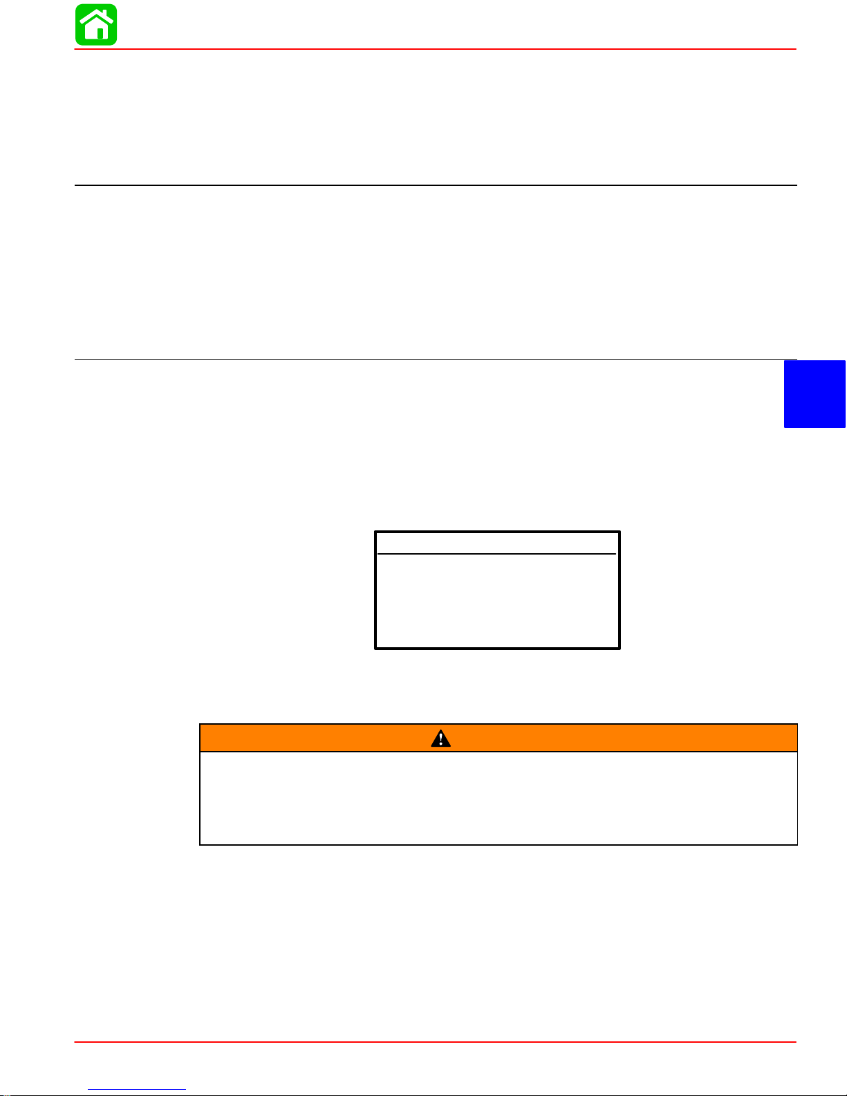
Dual Engine Center Line Dimension
b
d
c
a
a-28.5 in. (724 mm)
b-12.5 in. (317 mm)
c-17.8 in. (453 mm)
d-32 Degree
Page 1D-2 90-888465 JUNE 2002
Page 3
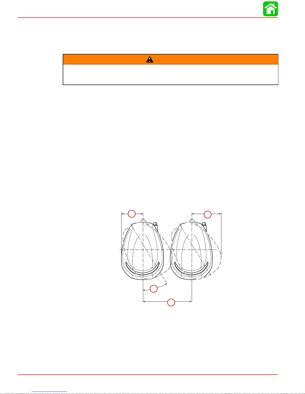
Lifting Outboard
Use 3 point strap 91-883705T.
a-3 point lift strap 91-883705T
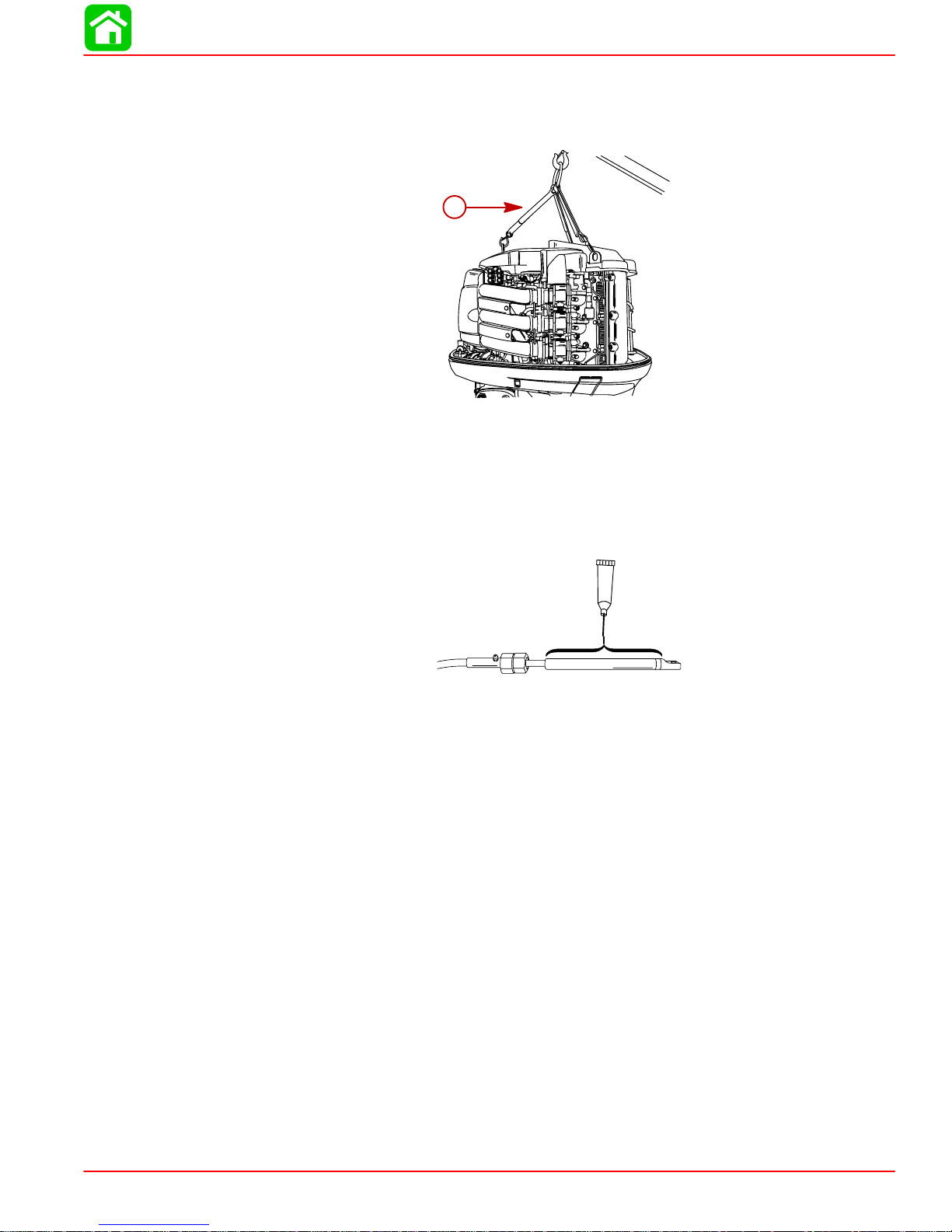
Steering Cable
OUTBOARD MOTOR INSTALLATION
a
STARBOARD SIDE ROUTED CABLE
1. Lubricate entire cable end.
a-2-4-C Marine Lubricant with Teflon
a
90-888465 JUNE 2002 Page 1D-3
Page 4
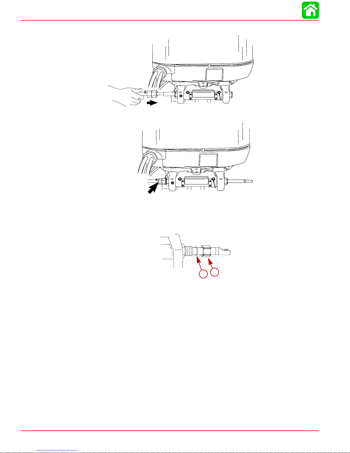
MAINTENANCE
2. Insert steering cable into tilt tube.
3. Torque nut to 47.5 Nm (35 lb. ft).
Steering Cable Seal
Install O-ring seal and cap.
a-O-ring Seal
b-Cap
b
a
Page 1D-4 90-888465 JUNE 2002
Page 5
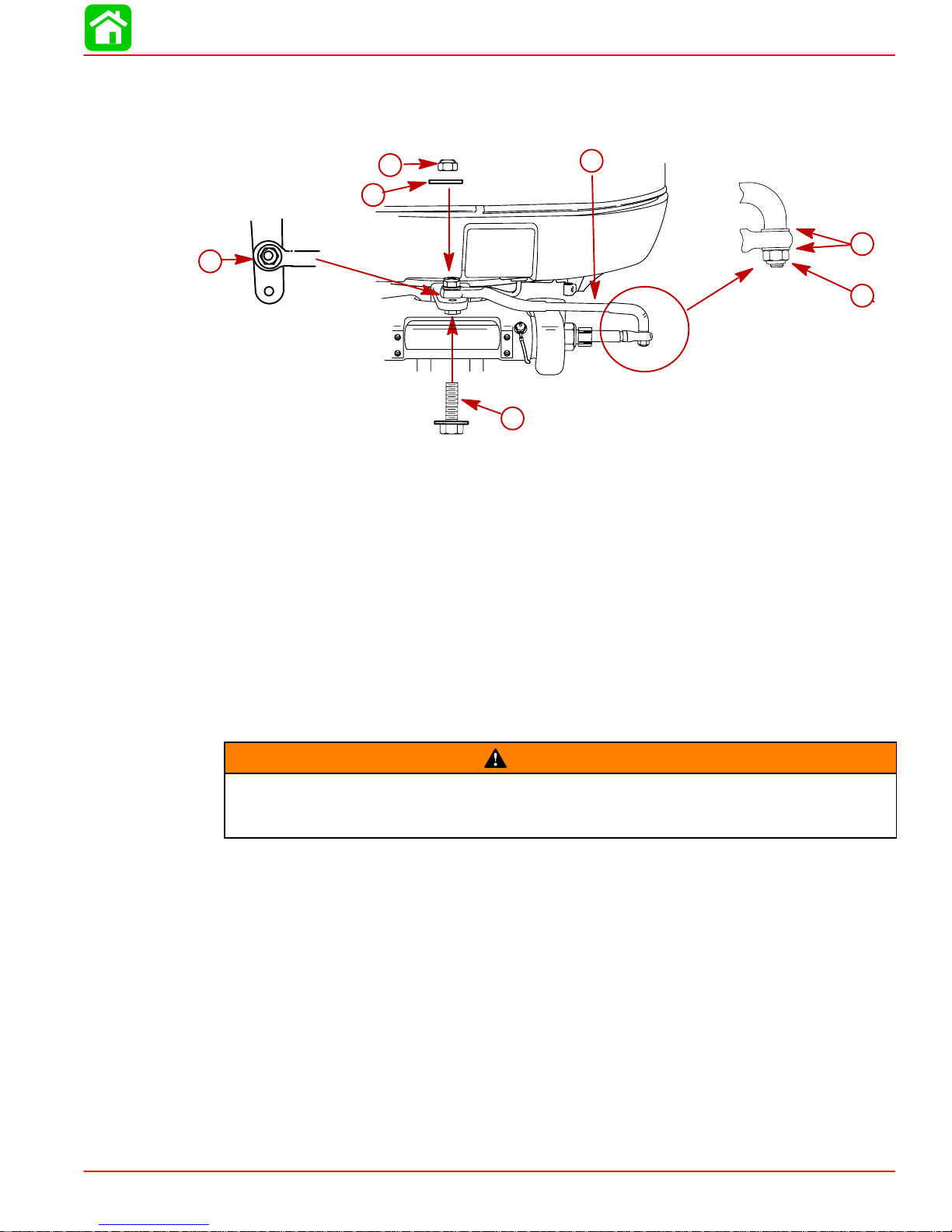
Steering Link Rod
1. Install steering link rod to rear hole on steering arm per illustration.
OUTBOARD MOTOR INSTALLATION
b
g
c
f
a
a-Special Bolt (10-856680) Torque to 27.1 Nm (20 lb. ft)
b-Nylon Insert Locknut (11-34932) Torque to 27.1 Nm (20 lb. ft)
c-Flat Washer
d-Nylon Insert Locknut (11-826709113) Tighten Locknut Until it Seats, Then Back
Nut Off 1/4 Turn
e-Flat Washer (2)
f-Install Steering Link Rod into Rear Hole
g-Steering Link Rod
IMPORTANT: The steering link rod that connects the steering cable to the engine
must be fastened using special washer head bolt (“a” – Part Number 10-856680) and
self locking nylon insert locknut (“d” - Part Number 11-826709113) and self locking
nylon insert locknut (“b” – Part Number 11-34932). These locknuts must never be replaced with common nuts (non locking) as they will work loose and vibrate off freeing
the link rod to disengage.
e
d
WARNING
Disengagement of a steering link rod can result in the boat taking a full, sudden,
sharp turn. This potentially violent action can cause occupants to be thrown overboard exposing them to serious injury or death.
90-888465 JUNE 2002 Page 1D-5
Page 6

MAINTENANCE
Installing Outboard
1. Use transom drilling fixture (91-98234A2) or attach (tape) engine mounting template (located in the installation manual) to boat transom.
2. Mark and drill four 17/32 in. (13.5mm) mounting holes.
3. Install the outboard so that the anti-ventilation plate is in-line with the bottom of the boat.
a
a-Anti-Ventilation Plate
4. Fasten outboard with provided mounting hardware shown.
b
a
e
a-1/2 in. Diameter Bolts (4)
b-Flat Washers(4)
c-Locknuts (4)
d-Flat Washers(4)
e-Marine Sealer - Apply to Shanks of Bolts, Not Threads
c
d
Page 1D-6 90-888465 JUNE 2002
Page 7

Front Cable Clamp Assembly
IMPORTANT: Sufficient slack must exist in engine wiring harness, battery cables,
and fuel hose routed between cable clamp and engine attachment point, to relieve
stress.
1. Bundle the fuel line, battery cables and wiring together and wrap with the piece of foam
(provided) as shown. Secure the wiring, battery cables, fuel line and foam together with
sta-straps.
2. Push the flap down over the top of the shift and throttle cable.
3. Lay the wrapped foam over the top of flap.
OUTBOARD MOTOR INSTALLATION
c
b
a
a-Shift and throttle cables
b-Flap - Position over the shift and throttle cables
c-Foam
d-Sta-Straps
d
90-888465 JUNE 2002 Page 1D-7
Page 8

MAINTENANCE
4. Install the top half of the cable clamp and reinstall the cowl bracket.
5. Slide the rigging tube onto the cable clamp and fasten with collar and hose clamp.
b
e
a
d
c
a-Top Half Cable Clamp
b-Cowl Bracket
c-Rigging Tube
Remote Wiring Harness
Route wiring harness through the front cable clamp. Connect wiring. Push the retainer over
the ends of the connectors. This will hold the connectors together. Secure connection in the
cowl with the releasable cable tie.
b
TAN
BRN/WHT
BLU/WHT
GRN/WHT
d-Collar
e-Hose Clamp
a
c
BLU/WHT
GRN/WHT
a-Power trim connectors
b-Retainer – Push Over Connector Ends
c-Releasable Cable Tie
Page 1D-8 90-888465 JUNE 2002
Page 9

Battery Cable Connections to the Engine
Route battery cables through the front cable clamp. Connect the battery cables to the terminals on the engine as shown.
NOTE: Bolts for fastening the battery cables terminals are located in the same packaging
kit that contains the front cable clamp.
(+)
a
(–)
b
OUTBOARD MOTOR INSTALLATION
(+) (–)
c
a-Battery Cable – Red Sleeve (Positive)
b-Battery Cable – Black Sleeve (Negative)
c-Screw M6 x 13 (10–821300 12) – Torque to 8 Nm (71 lb in.)
d-Screw M8 x 20 (10–818934 20) – Torque to 18 Nm (159 lb in.)
d
90-888465 JUNE 2002 Page 1D-9
Page 10

MAINTENANCE
Battery Cable Connections to the Battery
SINGLE OUTBOARD
a
b
(+)
DUAL OUTBOARDS
Connect a common ground cable (wire size same as engine battery cables) between negative (–) terminals on starting batteries.
a-Red Sleeve (Positive)
b-Black Sleeve (Negative)
c-Starting Battery
(–)
c
(–)
d-Ground Cable (Same Wire Size As Engine Battery Cable) – Connect Between
Negative (–) Terminals
Page 1D-10 90-888465 JUNE 2002
d
(–)
Page 11

Fuel Hose Connection
PORTABLE FUEL TANK
Select a suitable location in boat within engine fuel line length limitations and secure tank
in place.
PERMANENT FUEL TANK
These should be installed in accordance with industry and federal safety standards which
include recommendations applicable to grounding, anti-siphon protection, ventilation, etc.
FUEL HOSE SIZE
Minimum fuel line inside diameter (I.D.) is 8mm (5/16 in.), with separate fuel line/fuel tank
pickup for each engine.
FUEL HOSE CONNECTION
Route fuel hose through the front cable clamp. Fasten fuel hose to fitting with hose clamp.
OUTBOARD MOTOR INSTALLATION
b
a
a-Fuel Hose
b-Hose Clamp
90-888465 JUNE 2002 Page 1D-11
Page 12

MAINTENANCE
Shift Cable Installation
Install cables into t he r emote c ontrol f ollowing t h e i nstructions p rovided w ith t he r emote c ontrol.
NOTE: Install the shift cable to the engine first. The shift cable is the first cable to move when
the remote control handle is moved out of neutral.
1. Position remote control into neutral.
2. Shift outboard into neutral.
3. Align the shift pin with the center mark.
N
a-Shift Pin
b-Center Mark
NRF
a
b
Page 1D-12 90-888465 JUNE 2002
Page 13

OUTBOARD MOTOR INSTALLATION
4. Place shift cable on t he s hift pi n. A djust c able b arrel s o i t s lips f reely i nto t he b arrel h older.
5. Fasten cable to the shift pin with hairpin cotter.
c
d
c-Cable Barrel
d-Hair Pin Cotter
6. Check shift cable adjustments as follows:
a. Shift remote control into forward. The propeller shaft should be locked in gear . If not,
adjust the barrel closer to the cable end.
b. Shift remote control into neutral. The propeller shaft should turn freely without drag.
If not, adjust the barrel away from the cable end. Repeat steps a and b.
c. Shift remote control into reverse while turning propeller. The propeller shaft should
be locked in gear. If not, adjust the barrel away from the cable end. Repeat steps a
through c.
d. Shift remote control back to neutral. The propeller shaft should turn freely without
drag. If not, adjust the barrel closer to the cable end. Repeat steps a through d.
90-888465 JUNE 2002 Page 1D-13
Page 14

MAINTENANCE
Throttle Cable Installation
Install cables into the remote control following the instructions provided with the remote control.
1. Position remote control into neutral.
2. Install throttle cable to the throttle arm with hairpin cotter.
3. Adjust the cable barrel until the alignment mark on the cam lines up with center of the
roller.
4. Place cable barrel into retainer.
N
5. Lock the cable barrels in place with the cable latch.
c
d
e
a
b
f
a-Throttle Cable
b-Hairpin Cotter
c-Cable Barrel
Page 1D-14 90-888465 JUNE 2002
d-Throttle Cam
e-Alignment Mark
f-Cable Latch
Page 15

Propeller Installation
If the propeller shaft is rotated while the engine is in gear, there is the possibility that
the engine will crank over and start. To prevent this type of accidental engine starting and possible serious injury caused from being struck by a rotating propeller,
always shift outboard to neutral position and remove spark plug leads when you
are servicing the propeller.
Flo-Torq I Drive Hub Propellers
OUTBOARD MOTOR INSTALLATION
WARNING
f
e
d
b
a
c
g
a-Forward Thrust Hub
b-Replaceable Drive Sleeve
c-Propeller
d-Rear Thrust Hub
e-Washer
f-Propeller Nut- Torque To 54 Nm (40 lb- ft)
g-Cotter Pin – Bend the cotter pin ends.
NOTE: If the propeller nut does not align with the propeller shaft after tightening to the speci-
fied torque, then tighten the nut further to align it with the hole.
90-888465 JUNE 2002 Page 1D-15
Page 16

MAINTENANCE
Trim Tab Adjustment
The trim tab can be adjusted within limits to help compensate for steering torque.
Adjust trim tab as follows:
1. If boat tends to pull to the right, move the rear edge of the trim tab to the right.
2. If boat tends to pull to the left, move the rear edge of the trim tab to the left.
NOTE: Trim tab adjustment will have little effect reducing steering torque if the anti-ventilation plate is raised 50mm (2 in.) or more above the boat bottom.
Page 1D-16 90-888465 JUNE 2002
 Loading...