

Page 1

INSTALLATION MANUAL
75, 90 AND 115 HP (4-Stroke)
NOTICE TO INSTALLER: After completing assembly, these instructions should be
placed with the product for the owner’s future use.
IMPORT ANT: If the boat is to be water tested, the operator should be familiar with the
operation procedures in the Operation and Maintenance Manual.
Electric Fuel Pump 1. . . . . . . . . . . . . . . . . . . . . . . . .
Boat Horsepower Capacity 1. . . . . . . . . . . . . . . . . .
Start in Gear Protection 2. . . . . . . . . . . . . . . . . . . . .
Selecting Accessories For The Outboard 2. . . . . .
Installation Specifications 2. . . . . . . . . . . . . . . . . . . .
Lifting Outboard 3. . . . . . . . . . . . . . . . . . . . . . . . . . . .
Steering Cable 3. . . . . . . . . . . . . . . . . . . . . . . . . . . . .
Steering Link Rod 4. . . . . . . . . . . . . . . . . . . . . . . . . .
Installing Outboard 5. . . . . . . . . . . . . . . . . . . . . . . . .
Electrical, Hoses and Control Cables 7. . . . . . . . .
Front Cowl Grommet 7. . . . . . . . . . . . . . . . . . . . . .
Electric Fuel Pump
If an electric fuel pump is used, the fuel pressure must not exceed 4 psig at the engine. If
necessary, install a pressure regulator to regulate the pressure.
Boat Horsepower Capacity
U.S. COAST GUARD CAPACITY
Remote Wiring Harness 7. . . . . . . . . . . . . . . . . . . .
Battery Cable Connections 8. . . . . . . . . . . . . . . . .
Fuel Hose 9. . . . . . . . . . . . . . . . . . . . . . . . . . . . . . .
Speedometer (Optional) Water Pick-up 9. . . . . .
75 and 90 Hp Shift Cable Installation 10. . . . . . .
75 and 90 Hp Throttle Cable Installation 12. . . . .
115 Hp Shift Cable Installation 13. . . . . . . . . . . . .
115 Hp Throttle Cable Installation 15. . . . . . . . . .
Propeller Installation 16. . . . . . . . . . . . . . . . . . . . . . .
Trim-In Stop Adjustment 17. . . . . . . . . . . . . . . . . . .
Trim Tab Adjustment 18. . . . . . . . . . . . . . . . . . . . . . .
MAXIMUM HORSEPOWER XXX
MAXIMUM PERSON
CAPACITY (POUNDS) XXX
MAXIMUM WEIGHT
CAPACITY XXX
Do not overpower or overload the boat. Most boats will carry a required capacity plate indicating the maximum acceptable power and load as determined by the manufacturer following certain federal guidelines. If in doubt, contact your dealer or the boat manufacturer.
WARNING
Using an outboard that exceeds the maximum horsepower limit of a boat can:
1. cause loss of boat control 2. place too much weight at the transom, altering
the designed flotation characteristics of the boat or 3. cause the boat to break
apart, particularly around the transom area. Overpowering a boat can result in
serious injury, death, or boat damage.
90-10216040 JANUARY 2003 Printed in U.S.A. - 2003, Mercury Marine Page 1 of 18
Page 2
75, 90 and 115 (4-STROKE) INSTALLATION MANUAL
Start in Gear Protection
The remote control connected to the outboard must be equipped with a start-in-gear
protection device. This prevents the engine from starting in gear.
WARNING
Avoid serious injury or death from a sudden unexpected acceleration when starting
your engine. The design of this outboard requires that the remote control used with
it must have a built in start-in-gear protection device.
Selecting Accessories For The Outboard
Genuine Quicksilver Parts and Accessories have been specifically designed and tested for
this outboard.
Some accessories not manufactured or sold by Quicksilver are not designed to be safely
used with this outboard or outboard operating system. Acquire and read the Installation,
Operation, and Maintenance manuals for all selected accessories.
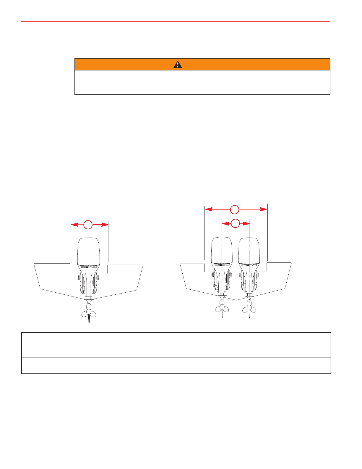
Installation Specifications
a
a – Transom Opening – Minimum
Single Engine – 33 in. (838.2)
Dual Engines – 59 in. (1498.6 mm)
b – Engine Center Line For Dual Engine
26 in. (660mm) Minimum
a
b
Page 2 of 18
Page 3
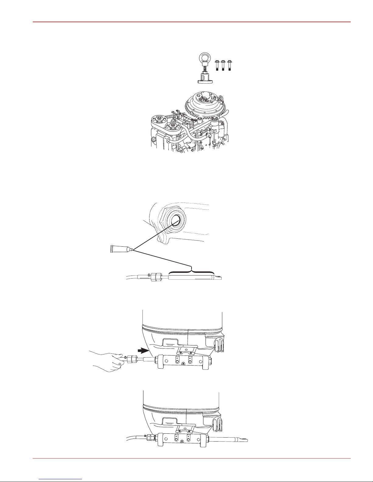
Lifting Outboard
Use Flywheel Puller/Lifting Eye (91-83164M).
Steering Cable
STARBOARD SIDE ROUTED CABLE
1. Lubricate O-ring seal and entire cable end.
75, 90 and 115 (4-STROKE) INSTALLATION MANUAL
a
a-Quicksilver 2-4-C Marine Lubricant with Teflon
2. Insert steering cable into tilt tube.
3. Torque nut to 35 lb. ft. (47.5 N·m).
Page 3 of 18
Page 4
75, 90 and 115 (4-STROKE) INSTALLATION MANUAL
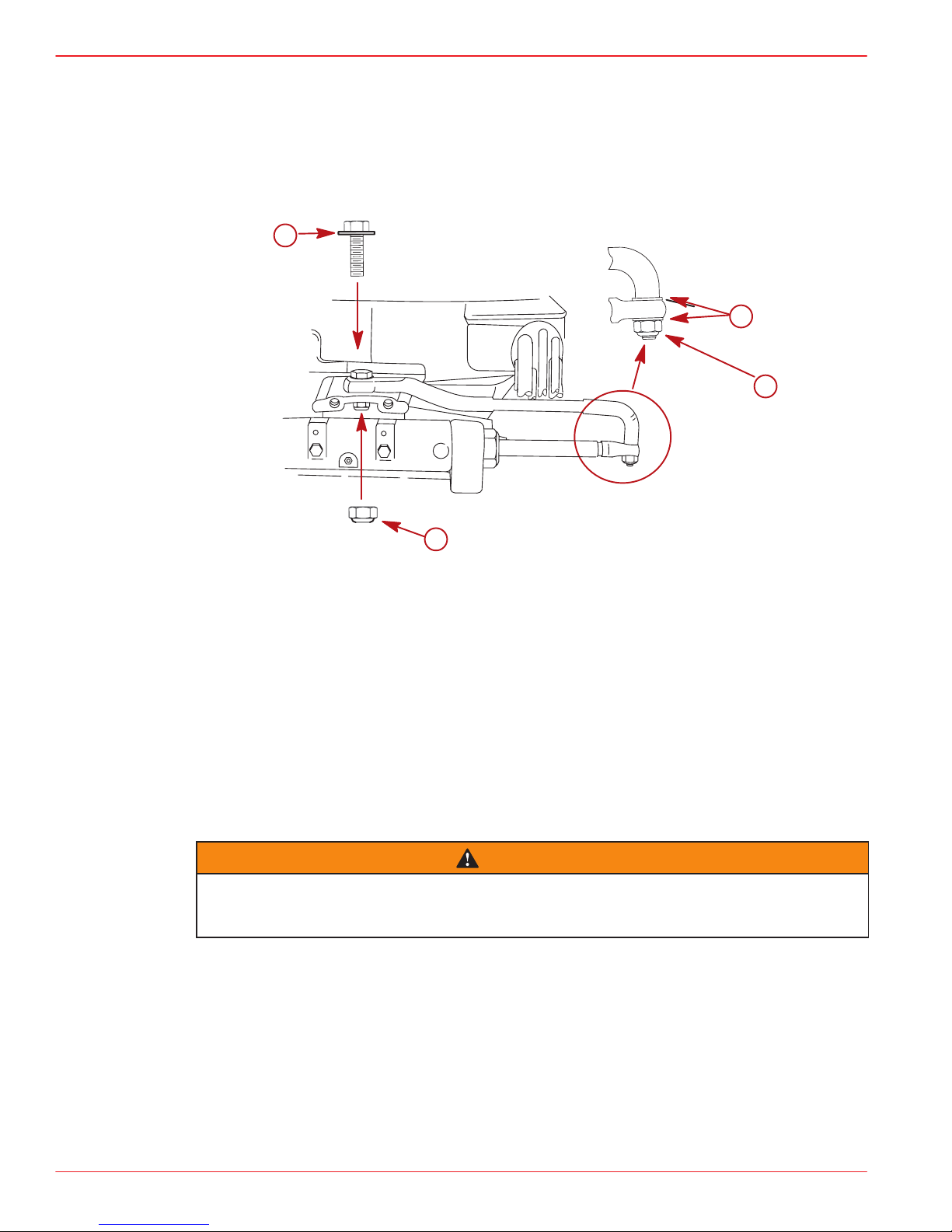
Steering Link Rod
Installation Note
NOTE: For ease of installation of special bolt (a) separate the front end of the bottom cowl.
1. Install steering link rod per illustration.
a
c
d
b
a-Special Bolt (10-90041) Torque to 20 lb. ft. (27.1 N·m)
b-Nylon Insert Locknut (11-34863) Torque to 20 lb. ft. (27.1 N·m)
c-Flat Washer (2)
d-Nylon Insert Locknut (11-34863) Tighten Locknut Until it Seats, Then Back Nut
Off 1/4 Turn
IMPORTANT: The steering link rod that connects the steering cable to the engine
must be fastened using special bolt (“a” - Part Number 10-90041) and self locking
nuts (“b” & “c” - Part Number 11-34863). These locknuts must never be replaced with
common nuts (non locking) as they will work loose and vibrate off, freeing the link
rod to disengage.
WARNING
Disengagement of a steering link rod can result in the boat taking a full, sudden,
sharp turn. This potentially violent action can cause occupants to be thrown overboard exposing them to serious injury or death.
Page 4 of 18
Page 5
75, 90 and 115 (4-STROKE) INSTALLATION MANUAL
Installing Outboard
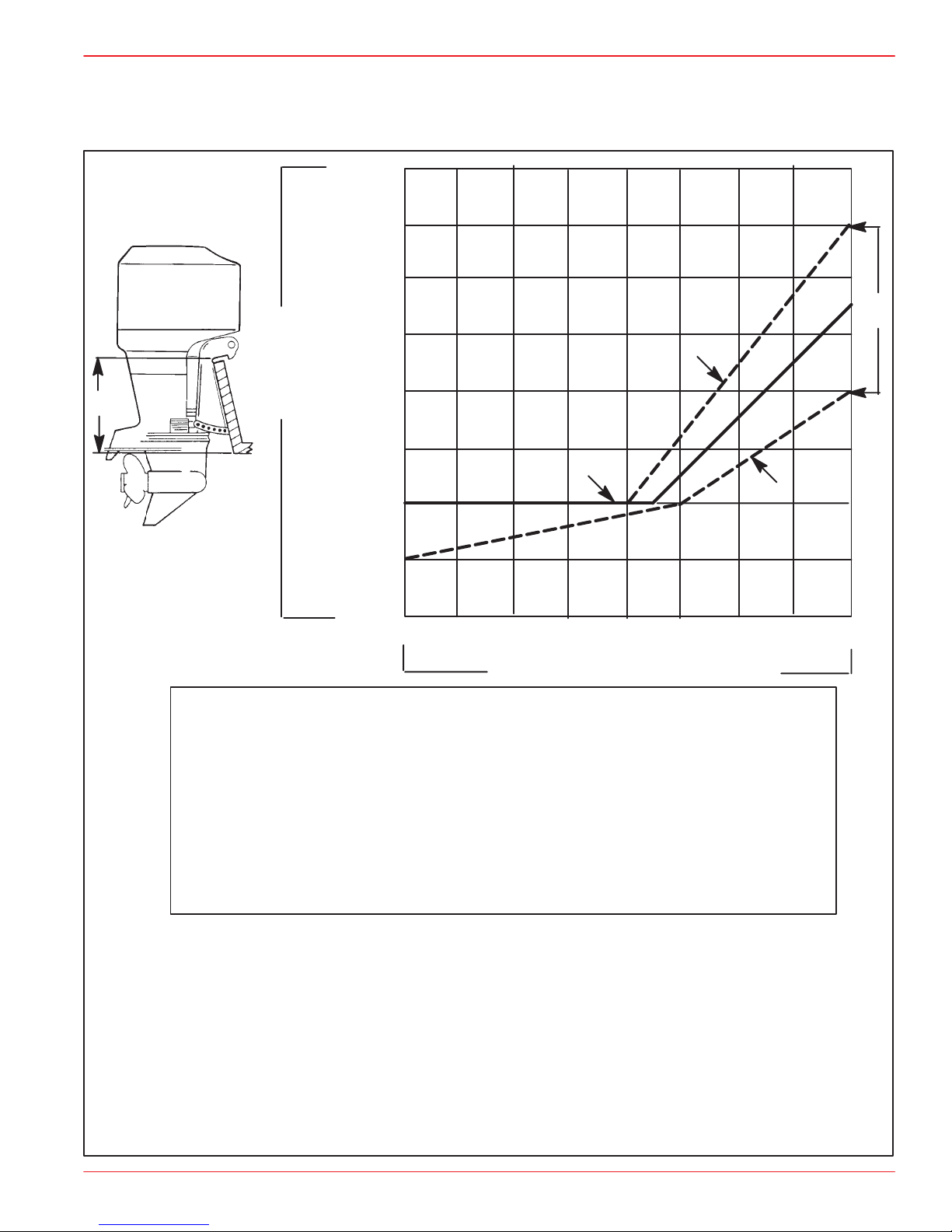
Determining Recommended Outboard Mounting Height
26 in.
(660mm)
25 in.
(635mm)
24 in.
(609mm)
(e)
Outboard
Mounting
Height
e
(See NOTE
Below)
23 in.
(584mm)
22 in.
(560mm)
21 in.
(533mm)
20 in.
(508mm)
a
b
c
d
19 in.
(482mm)
NOTE: Add 5 in. (127mm) for XL models to the listed outboard mounting
height.
IMPORTANT
NOTICE TO INSTALLER
1. The outboard should be mounted high enough on the transom so that the exhaust
relief hole will stay at least 1 in. (25.4 mm) above the water line when the engine is
running at idle speed. Having the exhaust relief hole above the water line will prevent
exhaust restriction. Exhaust restriction will result in poor performance at idle.
2. However, keep in mind that the mounting height (e) of the outboard must not exceed
25 in. (635 mm) for L models, 30 in. (762 mm) for XL models. Mounting the outboard
higher may cause damage to the gear case components.
This solid line is recommended to determine the out-
a.
board mounting height.
IMPORTANT: Increasing the height of outboard generally will provide the following: 1) Less steering torque,
2) more top speed, 3) greater boat stability, but, 4) will
cause more prop “break loose” which may be particularly noticeable when planing off or with heavy load.
These broken lines represent the extremes of known
successful outboard mounting height dimensions.
b.
10
20 30 40 50 60 70 80
Maximum Boat Speed Anticipated
c.
This line may be preferred to determine outboard
mounting height dimension, if maximum speed is the
only objective.
This line may be preferred to determine outboard
d.
mounting height dimension for dual outboard installation.
Outboard mounting height (height of outboard transom
e.
brackets from bottom of boat transom). For heights over
22 in. (560mm), a propeller, that is designed for surfacing operation is usually preferred.
Page 5 of 18
Page 6
75, 90 and 115 (4-STROKE) INSTALLATION MANUAL
Installing Outboard
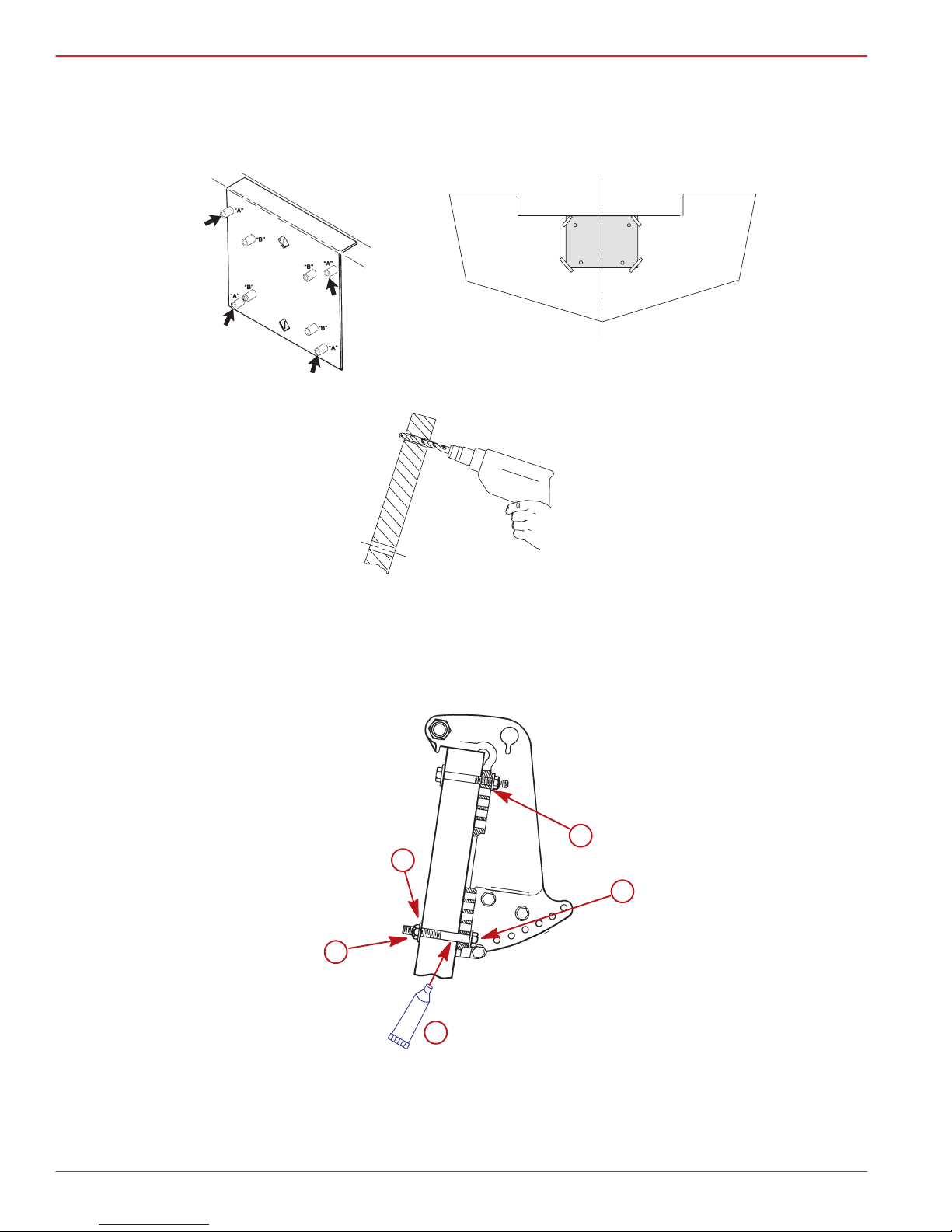
1. Use transom drilling fixture (91-98234A2) or attach (tape) engine mounting template
(located in this manual) to boat transom.
2. Mark and drill four 17/32 in. (13.5mm) mounting holes.
3. Refer to “Determining Recommended Outboard Motor Mounting Height”, preceding,
and install outboard to the nearest recommended mounting height.
4. Fasten outboard with provided mounting hardware shown.
NOTE: The addition of the four flat washers (d) is a manufacturing running change. Outboards built before the running change will not have the flat washers.
d
b
a
c
e
a-1/2 in. Diameter Bolts (4)
b-Flat Washers(4)
c-Locknuts (4)
d-Flat Washers(4)
e-Marine Sealer - Apply to Shanks of Bolts, Not Threads
Page 6 of 18
Page 7

Electrical, Hoses, and Control Cables
IMPORTANT: Warning Horn Requirement – The remote control or key switch
assembly must be wired with a warning horn. This warning horn is used with the
engine warning system.
Front Cowl Grommet
Pull up the cowl seal and remove the cover from the bottom cowl.
Route the hoses, wiring and cables through the correct openings in the rubber grommet as
shown.
a
b
i
75, 90 and 115 (4-STROKE) INSTALLATION MANUAL
d
e
c
f
g
h
a-Cover
b-Rubber Grommet
c-Fuel Hose Opening
d-Remote Wiring Harness Opening
e-Throttle Cable Opening
Remote Wiring Harness
Route wiring harness through the rubber grommet. Connect wiring. Push the retainer over
the exposed ends of the connectors. This will hold the connectors together.
b
BLU/WHT
GRN/WHT
f-Battery Cables Opening
g-Shift Cable Opening
h-Speedometer Tube
i-Sta-Strap (Included in Parts Bag) – Tie
Around Grommet After Components
are Installed
a
BLU/WHT
TAN
GRN/WHT
BRN/WHT
a-Power Trim Connections
b-Retainer – Push Over Connector Ends
Page 7 of 18
Page 8

75, 90 and 115 (4-STROKE) INSTALLATION MANUAL
Battery Cable Connections
SINGLE OUTBOARD
b
a
(+)
DUAL OUTBOARDS
Connect a common ground cable (wire size same as engine battery cables) between
negative (–) terminals on starting batteries.
(–)
a-Red Sleeve (Positive)
b-Black Sleeve (Negative)
c-Starting Battery
(–)
c
d
(–)
d-Ground Cable (Same Wire Size As Engine Battery Cable) – Connect Between
Negative (–) Terminals
Page 8 of 18
Page 9

Fuel Hose
PORTABLE FUEL TANK
Select a suitable location in boat within engine fuel line length limitations and secure tank
in place.
PERMANENT FUEL TANK
These should be installed in accordance with industry and federal safety standards which
include recommendations applicable to grounding, anti-siphon protection, ventilation, etc.
FUEL HOSE SIZE
Minimum fuel line inside diameter (I.D.) is 5/16 in. (8mm), with separate fuel line/fuel tank
pickup for each engine.
FUEL HOSE CONNECTION
Fasten remote fuel hose to fitting with hose clamp.
Speedometer (Optional) Water Pick-up
This outboard is equipped with a speedometer water pick-up located in the leading edge
of the gear case. If this water pick-up is to be used, locate the hose coming out of the front
grommet. Cut off the end of the hose fitting and make the connection.
75, 90 and 115 (4-STROKE) INSTALLATION MANUAL
NOTE: If the speedometer water pick-up hose is not used, keep the hose routed out of the
rubber grommet.
a-Fuel Hose
b-Hose Clamp – Secure Remote Fuel Hose
c-Speedometer Water Pick-up Hose for Optional Speedometer
Prevent possible water leakage. Water pick up hose must be routed through grommet and outside of lower cowl at all times.
a
c
b
CAUTION
Page 9 of 18
Page 10

75, 90 and 115 (4-STROKE) INSTALLATION MANUAL
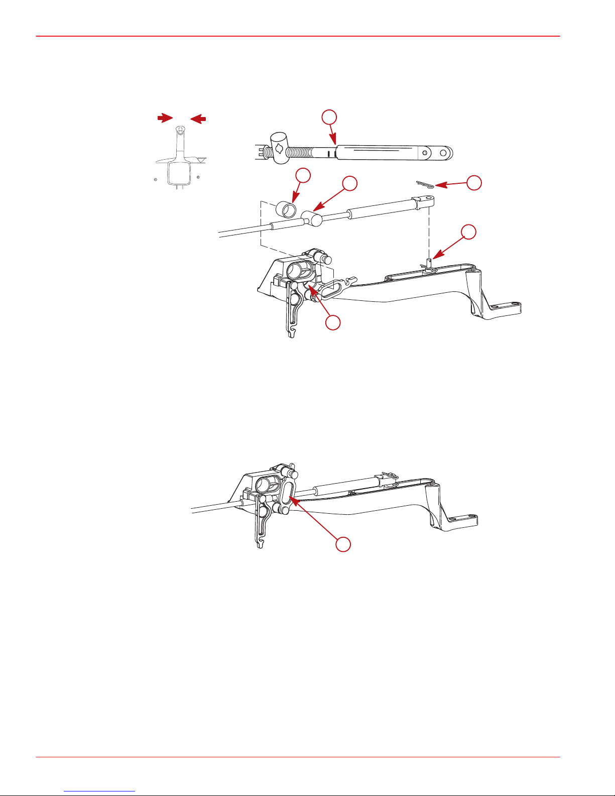
75 and 90 Hp Shift Cable Installation
Install cables into the remote control following the instructions provided with the remote
control.
NOTE: Install the shift cable to the engine first. The shift cable is the first cable to move when
the remote control handle is moved out of neutral.
1. Position the shift mechanism into the neutral potion.
2. Locate the center point of the slack or lost motion that exists in the shift cable as follows:
a. Move the remote control handle from neutral into forward and advance the handle
to full speed position. Slowly return the handle back to the neutral. Place a mark (a)
on the cable against the cable end guide.
N
b. Move the remote control handle from neutral into reverse and advance the handle
to full speed position. Slowly return the handle back to the neutral. Place a mark (b)
on the cable against the cable end guide.
c. Make a center mark (c), midway between marks (“a” and “b”). Align the cable end
guide against this center mark when installing cable to the engine.
a
b
c
3. Fit shift cable through rubber grommet.
Page 10 of 18
Page 11

75, 90 and 115 (4-STROKE) INSTALLATION MANUAL
4. Position remote control into neutral.
5. Align the shift cable end guide with the center point made in Step 2. Place shift cable
on anchor pin. Adjust cable barrel so it slips freely into the barrel holder.
6. Secure shift cable to the anchor pin with hair pin retainer.
N
a-Center Mark
b-Anchor Pin
c-Barrel Insert
d-Cable Barrel
e-Barrel Holder
f-Hair Pin Retainer
a
c
d
f
b
e
7. Lock cable barrel in place with cable latch.
a
a-Cable Latch
8. Check shift cable adjustments as follows:
a. Shift remote control into forward. The propeller shaft should be locked in gear . If not,
adjust the barrel closer to the cable end.
b. Shift remote control into neutral. The propeller shaft should turn freely without drag.
If not, adjust the barrel away from the cable end. Repeat steps a and b.
c. Shift remote control into reverse while turning propeller. The propeller shaft should
be locked in gear. If not, adjust the barrel away from the cable end. Repeat steps a
thru c.
d. Shift remote control back to neutral. The propeller shaft should turn freely without
drag. If not, adjust the barrel closer to the cable end. Repeat steps a thru d.
Page 11 of 18
Page 12

75, 90 and 115 (4-STROKE) INSTALLATION MANUAL
75 and 90 Hp Throttle Cable Installation
Install cables into the remote control following the instructions provided with the remote
control.
1. Position remote control into neutral.
N
2. Install throttle cable to the throttle arm with hairpin cotter.
3. Adjust the cable barrel so that the installed throttle cable will hold the throttle arm against
the idle stop.
4. Place cable barrel into retainer and install.
5. Fit throttle cable through the rubber grommet.
6. Lock the cable barrel in place with the cable latch.
c
a
f
e
b
d
h
a-Flat Washer
b-Hairpin Cotter
c-Cable Barrel
d-Barrel Retainer –
Toward Rear
Page 12 of 18
g
e-Throttle Arm
f-Idle Stop
g-Throttle Cable Opening
h-Cable Latch
Page 13

115 Hp Shift Cable Installation
Install cables into the remote control following the instructions provided with the remote
control.
NOTE: Install the shift cable to the engine first. The shift cable is the first cable to move when
the remote control handle is moved out of neutral.
1. Position the shift mechanism into the neutral potion.
2. Locate the center point of the slack or lost motion that exists in the shift cable as follows:
75, 90 and 115 (4-STROKE) INSTALLATION MANUAL
N
a. Move the remote control handle from neutral into forward and advance the handle
to full speed position. Slowly return the handle back to the neutral. Place a mark (a)
on the cable against the cable end guide.
b. Move the remote control handle from neutral into reverse and advance the handle
to full speed position. Slowly return the handle back to the neutral. Place a mark (b)
on the cable against the cable end guide.
c. Make a center mark (c), midway between marks (“a” and “b”). Align the cable end
guide against this center mark when installing cable to the engine.
a
b
c
3. Fit shift cable through rubber grommet.
Page 13 of 18
Page 14
75, 90 and 115 (4-STROKE) INSTALLATION MANUAL
4. Position remote control into neutral.
5. Align the shift cable end guide with the center point made in Step 2. Place shift cable
on anchor pin. Adjust cable barrel so it slips freely into the barrel holder.
6. Secure shift cable to the anchor pin with hair pin retainer.
N
a-Center Mark
b-Anchor Pin
c-Barrel Insert
d-Barrel
e-Barrel Holder
f-Hair Pin Retainer
a
c
d
f
b
e
7. Lock barrel in place with cable latch.
a
a-Cable Latch
8. Check shift cable adjustments as follows:
a. Shift remote control into forward. The propeller shaft should be locked in gear . If not,
adjust the barrel closer to the cable end.
b. Shift remote control into neutral. The propeller shaft should turn freely without drag.
If not, adjust the barrel away from the cable end. Repeat steps a and b.
c. Shift remote control into reverse while turning propeller. The propeller shaft should
be locked in gear. If not, adjust the barrel away from the cable end. Repeat steps a
thru c.
d. Shift remote control back to neutral. The propeller shaft should turn freely without
drag. If not, adjust the barrel closer to the cable end. Repeat steps a thru d.
Page 14 of 18
Page 15

115 Hp Throttle Cable Installation
Install cables into the remote control following the instructions provided with the remote
control.
1. Position remote control into neutral.
N
2. Install throttle cable to the throttle arm with hairpin cotter.
3. Adjust the cable barrel so that the installed throttle cable will hold the throttle arm against
the idle stop.
4. Place cable barrel into retainer and install.
5. Fit throttle cable through the rubber grommet.
75, 90 and 115 (4-STROKE) INSTALLATION MANUAL
6. Lock the retainer in place with the cable latch.
d
c
e
f
a
b
a-Flat Washer
b-Hairpin Cotter
c-Cable Barrel
d-Throttle Arm
g
e-Barrel Retainer – Align with
“115” Mark
f-Cable Latch
g-Throttle Cable Opening
Page 15 of 18
Page 16

75, 90 and 115 (4-STROKE) INSTALLATION MANUAL
Propeller Installation
If the propeller shaft is rotated while the engine is in gear, there is the possibility that
the engine will crank over and start. To prevent this type of accidental engine starting and possible serious injury caused from being struck by a rotating propeller,
always shift outboard to neutral position and remove spark plug leads when you
are servicing the propeller.
Flo-Torq I Drive Hub Propellers
b
WARNING
e
a-Forward Thrust Hub
b-Continuity Washer
c-Thrust Hub
d-Propeller Nut Retainer
e-Propeller Nut
Flo-Torq II and Flo-Torq lll Drive Hub Propellers
Flo-Torq ll
e
c
d
b
a-Forward Thrust Hub
b-Replaceable Drive Sleeve
c-Rear Thrust Hub
d-Propeller Nut Retainer
e-Propeller Nut
c
d
a
Flo-Torq lll
e
a
d
c
b
a
7. Tighten propeller nut to 55 lb-ft (75 Nm). Bend tabs against nut.
a-Propeller Nut - Torque To 55 lb- ft (75 Nm)
b-Bend Tabs Into Grooves
Page 16 of 18
a
b
Page 17

Trim-In Stop Adjustment
Some outboard boats, particularly some bass boats, are built with a greater than normal
transom angle which will allow the outboard to be trimmed further “in” or “under”. This greater trim “under” capability is desirable to improve acceleration, reduce the angle and time
spend in a bow high boat attitude during planing off, and in some cases, may be necessary
to plane off a boat with aft live wells, given the variety of available propellers and height
range of engine installations.
However, once on plane, the engine should be trimmed to a more intermediate position to
avoid a bow-down planing condition called “plowing”. Plowing can cause “bow steering” or
“over steering” and inefficiently consumes horsepower . In this condition, if attempting a turn
or encountering a diagonal, moderate wake, a more abrupt turn than intended may result.
In rare circumstances, the owner may decide to limit the trim under. This can be accomplished by purchasing a stainless steel tilt pin (P/N 17-49930A1) and inserting it through
whatever pin hole is desired. The non-stainless steel shipping bolt should not be used in this
application other than on a temporary basis.
Avoid possible serious injury or death. Adjust outboard to an intermediate trim position as soon as boat is on plane to avoid possible ejection due to boat spin-out.
Do not attempt to turn boat when engine is trimmed extremely under or in.
75, 90 and 115 (4-STROKE) INSTALLATION MANUAL
WARNING
a-Stainless Steel Tilt Pin
a
Page 17 of 18
Page 18

75, 90 and 115 (4-STROKE) INSTALLATION MANUAL
Trim Tab Adjustment
The trim tab can be adjusted within limits to help compensate for steering torque.
Adjust trim tab as follows:
1. If boat tends to pull to the right, move the rear edge of the trim tab to the right.
2. If boat tends to pull to the left, move the rear edge of the trim tab to the left.
NOTE: Trim tab adjustment will have little effect reducing steering torque if the
anti-ventilation plate is raised 2 inches (50mm) or more above the boat bottom.
Page 18 of 18
 Loading...