

Page 1
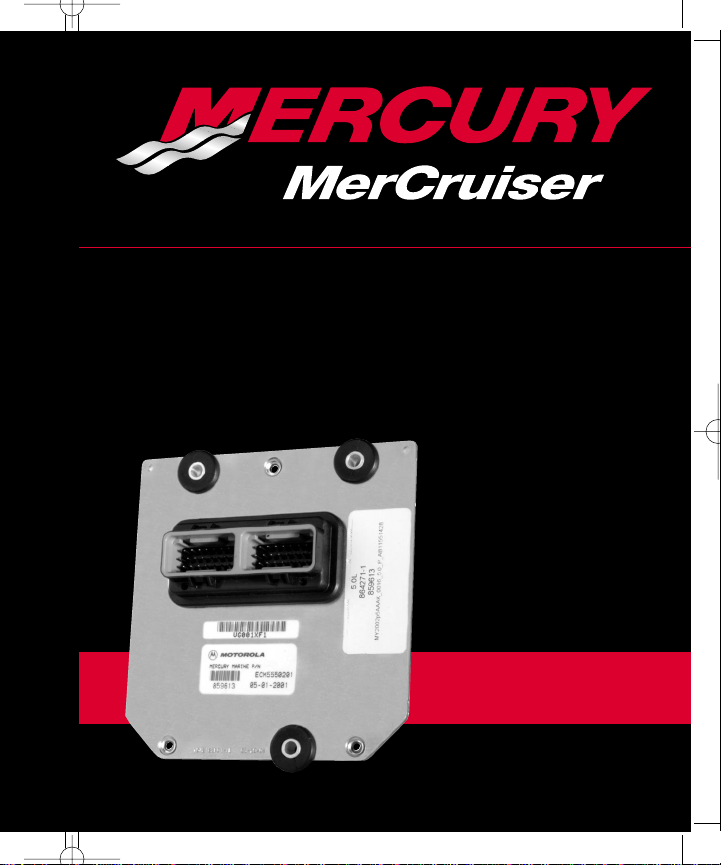
#36 ECM 555 Diagnostics
VIEW
S/N OM300000 and Above
#36 Service Manual
ECM 555 Diagnostics
Serial Number
0M300000 and Above
Page 2
Notice
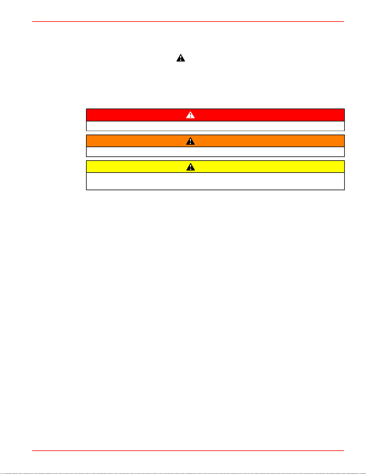
Throughout this publication, Dangers, Warnings and Cautions (accompanied by the
International HAZARD Symbol
concerning a particular service or operation that may be hazardous if performed incorrectly
or carelessly. OBSERVE THEM CAREFULLY!
These Safety Alerts alone cannot eliminate the hazards that they signal. Strict compliance
to these special instructions when performing the service, plus common sense operation,
are major accident prevention measures.
Immediate hazards which will result in severe personal injury or death.
Hazards or unsafe practices which could result in severe personal injury or death.
Hazards or unsafe practices which could result in minor personal injury or product
or property damage.
Notice to Users of This Manual
) are used to alert the mechanic to special instructions
DANGER
WARNING
CAUTION
This service manual has been written and published by the Service Department of Mercury
Marine to aid our dealers’ mechanics and company service personnel when servicing the
products described herein.
It is assumed that these personnel are familiar with marine product servicing procedures.
Furthermore, it is assumed that they have been trained in the recommended service
procedures of Mercury MerCruiser product, including the use of mechanics’ common hand
tools and the special Mercury Marine or recommended tools from other suppliers.
We could not possibly know of and advise the marine trade of all conceivable procedures
and of the possible hazards and/or results of each method. Therefore, anyone who uses
a service procedure and/or tool, which is not recommended by the manufacturer, first must
completely satisfy himself that neither his nor the products safety will be endangered.
All information, illustrations and specifications contained in this manual are based on the
latest product information available at the time of publication. As required, revisions to this
manual will be sent to all dealers contracted by us to sell and/or service these products.
We reserve the right to make changes to this manual without prior notification.
Refer to dealer service bulletins, operation maintenance and warranty manuals and
installation manuals for other pertinent information concerning the products described in
this manual.
90-864573 FEBRUARY 2002 Page i
Page 3

Precautions
It should be kept in mind, while working on the product, that the electrical system and ignition
system are capable of violent and damaging short circuits or severe electrical shocks. When
performing any work where electrical terminals could possibly be grounded or touched by
the mechanic, the battery cables should be disconnected at the battery.
Any time the intake or exhaust openings are exposed during service they should be covered
to protect against accidental entrance of foreign material which could enter the cylinders and
cause extensive internal damage when the engine is started.
It is important to note, during any maintenance procedure replacement fasteners must have
the same measurements and strength as those removed. Numbers on the heads of the
metric bolts and on the surfaces of metric nuts indicate their strength. American bolts use
radial lines for this purpose, while most American nuts do not have strength markings.
Mismatched or incorrect fasteners can result in damage or malfunction, or possibly personal
injury. Therefore, fasteners removed should be saved for reuse in the same locations
whenever possible. Where the fasteners are not satisfactory for re-use, care should be
taken to select a replacement that matches the original.
Engine Mechanical Components
Many of the engine mechanical components are designed for marine applications. Unlike
automotive engines, marine engines are subjected to extended periods of heavy load
and wide open throttle operation and, therefore, require heavy-duty components. Special
marine engine parts have design and manufacturing specifications that are required to
provide long life and dependable performance. Marine engine parts also must be able to
resist the corrosive action of salt or brackish water that will rust or corrode standard
automotive parts within a short period of time.
Failure to use recommended Quicksilver service replacement parts can result in poor
engine performance and/or durability, rapid corrosion of parts subjected to salt water and
possibly complete failure of the engine.
Replacement Parts
Electrical, ignition and fuel system components on MerCruiser Engines and
Sterndrives are designed and manufactured to comply with U.S. Coast Guard Rules
and Regulations to minimize risks of fire or explosion.
Use of replacement electrical, ignition or fuel system components, which do not
comply with these rules and regulations, could result in a fire or explosion hazard
and should be avoided.
When servicing the electrical, ignition and fuel systems, it is extremely important
that all components are properly installed and tightened. If not, any electrical or
ignition component opening would permit sparks to ignite fuel vapors from fuel
system leaks, if they existed.
Failure to use recommended Quicksilver service replacement parts can result in poor
engine performance and/or durability, rapid corrosion of parts subjected to salt water and
possibly complete failure of the engine.
Use of parts other than recommended service replacement parts will void the warranty on
those parts which are damaged as a result of the use of other than
recommended replacement parts.
WARNING
Page ii 90-864573 FEBRUARY 2002
Page 4
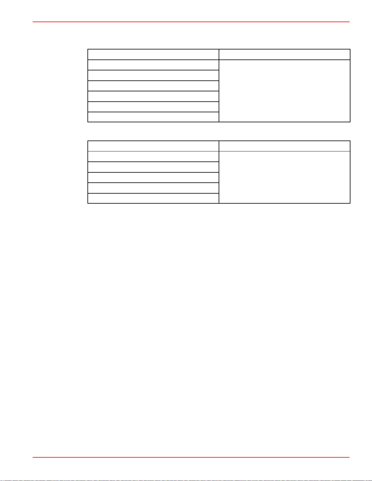
Models Covered in This Manual
0M30000
0andAb
Sterndrive (MCM) Serial Number
4.3L MPI Alpha and Bravo
5.0L MPI Alpha and Bravo
350 MAG MPI Alpha and Bravo
350 MAG MPI Alpha and Bravo Horizon
MX 6.2 MPI
MX 6.2 MPI Horizon
Inboard and Tow Sports (MIE) Serial Number
350 MAG MPI Inboard
350 MAG MPI Horizon Inboard
MX 6.2 MPI Inboard
MX 6.2 MPI Horizon Inboard
350 MAG MPI Tow Sports
0M310000 and Above
ove
90-864573 FEBRUARY 2002 Page iii
Page 5

THIS PAGE IS INTENTIONALLY BLANK
Page iv 90-864573 FEBRUARY 2002
Page 6

Service Manual Outline
Section 1 - General Information
General Information
1
Section 2 - Troubleshooting
Section 3 - Wiring Diagrams
Troubleshooting
2
Wiring Diagrams
3
5
8
90-864573 FEBRUARY 2002 Page v
Page 7

SECTION 1A - GENERAL INFORMATION
How To Use This Guide 1A-2..............
Abbreviations 1A-3.......................
Special Tools 1A-4.......................
Precautions 1A-10........................
Service Precautions 1A-12...............
General Specifications 1A-14...............
4.3 liter (262 cid) 1A-14.................
5.0 liter (305 cid) 1A-14.................
5.7 liter (350 cid) 1A-15.................
6.2 liter (377 cid) 1A-15.................
General Information 1A-16.................
Electrostatic Discharge Damage 1A-16....
Wiring Harness Service 1A-16............
Wiring Connector Service 1A-17..........
Intermittents 1A-18.....................
SECTION 2A - TROUBLESHOOTING
Troubleshooting
Without A Diagnostic Tool 2A-2............
Troubleshooting
With A Diagnostic Tool 2A-3..............
Troubleshooting Worksheet 2A-4...........
ECM Calibration Label 2A-4............
Data Collection 2A-5...................
PCM 555/ECM 555
Scan Tool Worksheet 2A-5.............
Preliminary Checks 2A-8..................
Visual / Physical Checklist 2A-8.........
On-Board Diagnostic
(OBD) System Chart 2A-9.............
Fuel Pressure Gauge Setup 2A-11........
Symptom Charts 2A-12....................
Chart A-1 Engine Cranks Over
But Will Not Start 2A-12.................
Chart A-2 Main Power Relay Test 2A-13...
Chart A-3 Fuel System Electrical Test 2A-14
Chart A-4 Fuel System Diagnosis 2A-15...
Chart A-5 Ignition System Test 2A-17.....
Chart A-6 Hard Start Symptom 2A-19.....
Chart A-7 Engine Surges Symptom 2A-22.
Electronic Control Module
(ECM) and Sensors 1A-20.................
General Description 1A-20...............
Computers and Voltage Signals 1A-20....
Analog Signals 1A-20...................
Digital Signals 1A-22....................
Engine Control Module (ECM) 1A-23......
Engine Guardian System 1A-24.............
General Description 1A-24...............
Warning Chart 1A-25....................
General Reference Charts 1A-28............
Manifold Vacuum / Pressure 1A-28.......
Vacuum Gauge vs MAP Sensor 1A-29....
Centigrade to Fahrenheit Conversion 1A-30
Chart A-8 Lack Of Power, Sluggish
or Spongy Symptom 2A-24..............
Chart A-9 Detonation /
Spark Knock Symptom 2A-26...........
Chart A-10 Hesitation, Sag
or Stumble Symptom 2A-29.............
Chart A-11 Cuts Out
or Misses Symptom 2A-31..............
Chart A-12 Rough, Unstable or
Incorrect Idle and Stalling Symptom 2A-33
Chart A-13 Poor Fuel
Economy Symptom 2A-35..............
Chart A-14 Dieseling or
Run-On Symptom 2A-37................
Chart A-15 Backfire Symptom 2A-38......
Symptom Quick Reference Chart 2A-40......
Engine Fault Quick Reference Chart 2A-43...
Injector Balance Test 2A-47................
Test Procedure 2A-47...................
Test Example 2A-49....................
Mercury MerCruiser
Scan Tool Flowchart 2A-50..............
Digital Diagnostic Terminal Flowchart 2A-51
Page vi 90-864573 FEBRUARY 2002
Page 8

SECTION 3A - WIRING DIAGRAMS
Sensor Locations 3A-2....................
Engine Harness Legend 3A-4..............
Wire Splice Description 3A-4............
Wire Color Code Abbreviations 3A-4.....
ECM Pinout 3A-5......................
ECM 555 EFI System Engine
Wiring Diagrams 3A-6....................
Typical Starting System 3A-6............
Wake, Horn and Tachometer Circuits 3A-8
Fuses, IAC and Relays 3A-9............
MAP/T, CPS and TPS 3A-10.............
ECT, Seawater Pump and
Oil Pressure Sensors 3A-11.............
Gear Indicator and Shift Interrupt 3A-12...
Fuel Injector Control Circuits
and Diagnostic Circuits 3A-13...........
Ignition System 3A-14...................
CAN, Fuel Level, Paddle Wheel
and Temperature Circuit 3A-15..........
Transom Harness 3A-16.................
Transom Connector (Engine Side) 3A-17..
Transom Harness (Transom Side) 3A-18..
Slave Solenoid Circuit 3A-19.............
Altenator Output Circuit 3A-20............
Engine 12 Volt Ground Circuit 3A-21......
Single Circuit Diagrams 3A-22..............
Seawater Pump Circuit 3A-22............
Diagnostics Circuit 3A-23................
Engine Coolant Temperature Circuit 3A-24.
IAC Circuit 3A-25.......................
MAP/T Circuit 3A-26....................
Throttle Position Circuit 3A-27............
Oil Pressure Circuit 3A-28...............
Knock Sensor Circuits 3A-29.............
Harness To Paddle Wheel
Connector Circuit 3A-30................
Fuel Level Circuit 3A-31.................
Fuel Pump Relay Circuit 3A-32...........
Control Area Network (CAN) Circuit 3A-33.
Wiring Diagrams 3A-34....................
90-864573 FEBRUARY 2002 Page vii
Page 9

THIS PAGE IS INTENTIONALLY BLANK
Page viii 90-864573 FEBRUARY 2002
Page 10

SERVICE MANUAL NUMBER 36
GENERAL INFORMATION
SECTION 1A - GENERAL INFORMATION
Table of Contents
How To Use This Guide 1A-2..............
Abbreviations 1A-3.......................
Special Tools 1A-4.......................
Precautions 1A-10........................
Service Precautions 1A-12...............
General Specifications 1A-14...............
4.3 liter (262 cid) 1A-14.................
5.0 liter (305 cid) 1A-14.................
5.7 liter (350 cid) 1A-15.................
6.2 liter (377 cid) 1A-15.................
General Information 1A-16.................
Electrostatic Discharge Damage 1A-16....
Wiring Harness Service 1A-16............
Wiring Connector Service 1A-17..........
Intermittents 1A-18.....................
1
A
Electronic Control Module
(ECM) and Sensors 1A-20.................
General Description 1A-20...............
Computers and Voltage Signals 1A-20....
Analog Signals 1A-20...................
Digital Signals 1A-22....................
Engine Control Module (ECM) 1A-23......
Engine Guardian System 1A-24.............
General Description 1A-24...............
Warning Chart 1A-25....................
General Reference Charts 1A-28............
Manifold Vacuum / Pressure 1A-28.......
Vacuum Gauge vs MAP Sensor 1A-29....
Centigrade to Fahrenheit Conversion 1A-30
90-864573 FEBRUARY 2002 Page 1A-1
Page 11

GENERAL INFORMATION SERVICE MANUAL NUMBER 36
How To Use This Guide
This diagnostic guide is separated into 3 sections: General Information, Troubleshooting
and Wiring Diagrams.
General Information covers:
General wiring information
Engine Guardian description
Warning chart
Troubleshooting covers:
Basic scan tool information
Symptom trouble chart
Fault chart
Wiring diagram covers:
Engine electrical harness
Circuit diagrams
Troubleshooting covers possible electrical and mechanical causes for engine faults on the
scan tool. In wiring diagrams, the single circuit diagrams cover each sensor and subset of
the electrical system of the engine. These two sections will help the technician pinpoint
problems occurring in the electrical system.
Page 1A-2 90-864573 FEBRUARY 2002
Page 12
SERVICE MANUAL NUMBER 36
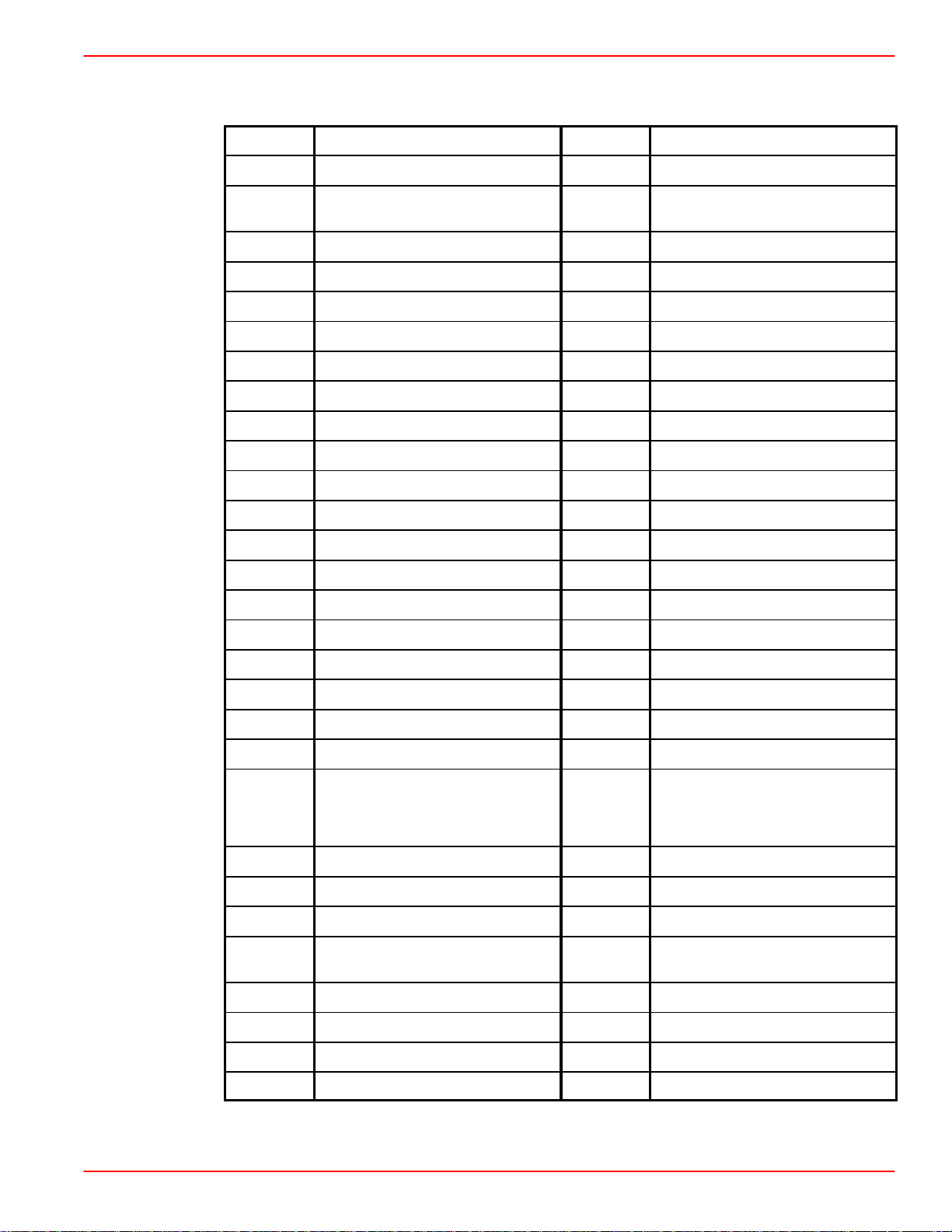
Abbreviations
amp Amperes in. hg Inches Of Mercury
BARO Barometric Pressure INJ Injector
GENERAL INFORMATION
Bat
Battery Positive Terminal, Bat-
tery or System Voltage
kPa Kilopascal
B+ Battery Positive Voltage KS Knock Sensor System
Bps Beeps kV Kilovolts
CAM Camshaft mA milliamperes
cond Condition MPR Main Power Relay
cont Continuous MAP Manifold Air Pressure
Crank Crankshaft MAT Manifold Air Temperature
CAN Control Area Network mohms Milliohms
CKT Circuit mSec Millisecond
CMP Camshaft Position Sensor N/C Normally Closed
Conn Connector N/O Normally Open
CPS Crankshaft Position Sensor OBD On-Board Diagnostic Test
Cyl Cylinder PCM Propulsion Control Module
DDT Digital Diagnostic Terminal RAM Random Access Memory
Deg Degrees REF HI Reference High
Diag Diagnostic REF LO Reference Low
DIS Distributorless Ignition System RFI Resistance Frequency Interval
DLC Data Link Connector ROM Read Only Memory
Dtc Diagnostic Trouble Code RPM Revolutions per Minute
DMM
DMT
Digital Multimeter SW Switch
DVOM
ECM Electronic Control Module TA CH Tachometer
ECT Engine Coolant Temperature TERM Terminal
EFI Electronic Fuel Injector TPS Throttle Position Sensor
EMCT
Exhaust Manifold Coolant
Temperature
V Volts
EST Electronic Spark Timing VA C Vacuum
GND Ground VDC Volt Direct Current
IAC Idle Air Control VOA Volt/Ohm/Amp Meter
IGN Ignition WOT Wide Open Throttle
90-864573 FEBRUARY 2002 Page 1A-3
Page 13
GENERAL INFORMATION SERVICE MANUAL NUMBER 36
Special Tools
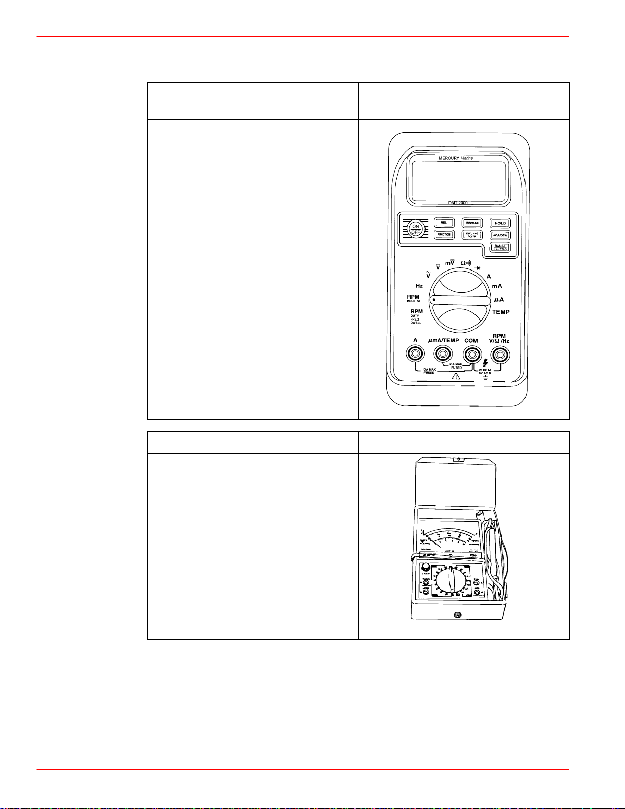
DMT 2000A Tachometer /
Multi-Meter Kit
Description:
Measures rpm on both 2 and 4 cycle
marine engines, records the maximums
and minimums simultaneously and will
read accurately in high RFI
environments.
Replacement Components:
91-854010-1 8 ft (2.4 m) Inductive
Pick-Up
91-854011-1 Temperature Probe
91-854012 Ferrite Core
91-854013-1 Interface Module
91-854014-1 Hard Carrying Case
91-854015-1 User’s Guide
91-802651 Test Leads
Optional Accessories:
84-854016T 8 ft (2.4 m) Inductive
Pick-Up Extension
91-802650 Clamp-On Current Probe
91-89045-1 Direct Voltage Adaptor
91-854009A3
77959
DVA / Multi-Meter Kit 91-99750A1
Description:
Tests the electrical and ignition systems;
consists of a VOA meter with built-in
direct voltage adaptor.
73609
Page 1A-4 90-864573 FEBRUARY 2002
Page 14
SERVICE MANUAL NUMBER 36
Special Tools (continued)
GENERAL INFORMATION
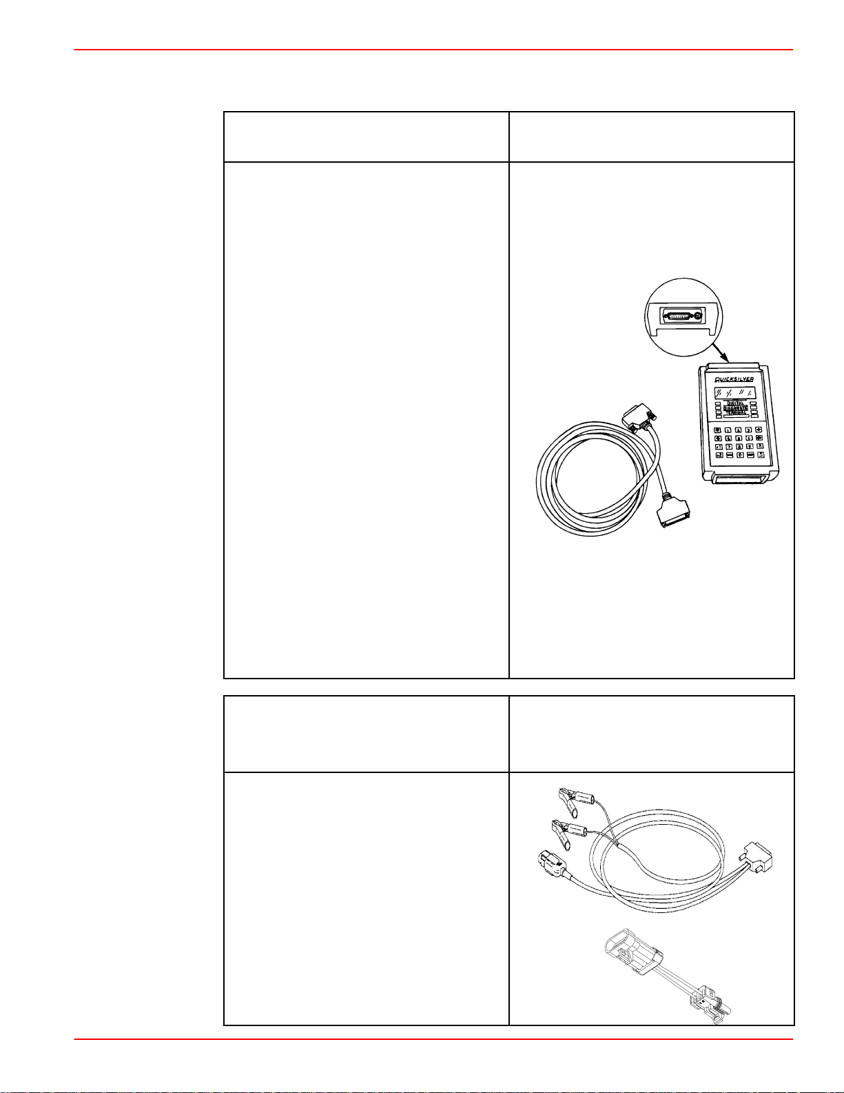
Digital Diagnostic Terminal
DDT
Description:
Display problem codes stored in the
ECM. It also allows the monitoring of
various circuits and components in the
fuel injection system. Must order the
91-803999 cartridge for MEFI 1, MEFI 2
and MEFI 3 ECM models 91-880118A2
cartridge for ECM 555 and PCM 555
models.
84-825003A1 Replacement 10 ft (3 m)
25-pin Harness
91-8404805 Optional Heavy Duty
Carrying case
Accessories:
An additional harness assembly may be
required when using the DDT, refer to
the following:
91-822560A13 Harness Assembly /
Diagnostic Tester
91-861540A1 Adaptor Harness
91-822560A7 Outboard Adapter
Harness
91-84-822560A5 EFI Outboard Adaptor
91-822560T12 Scan Tool Harness
Adaptor
91-822560A2 Harness Assembly /
Diagnostic Tester
91-823686A2
74214
EFI Outboard Harness
Adaptor
Scan Tool Harness Adaptor
Description:
84-822560A5 Outboard Harness
Adaptor may be used with
91-823686A32 DDT Scan Tool for PCM
555 and ECM 555 models.
Use the Harness Adaptor 84-822560T12
For PCM 555 Models to adapt the 4-pin
Mercury MerCruiser connector to the
2-pin 84-822560A5 Outboard Harness.
90-864573 FEBRUARY 2002 Page 1A-5
84-822560A5
84-822560T12
84-822560A5
84-822560T12
78069
78034
Page 15
GENERAL INFORMATION SERVICE MANUAL NUMBER 36
Special Tools (continued)
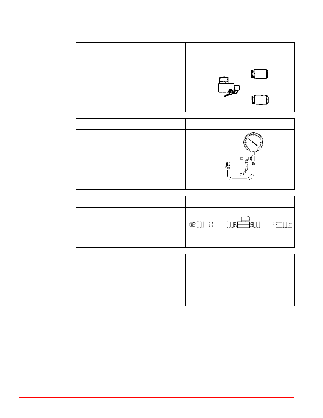
Fuel Pressure Gauge Adaptor
Kit
Description:
Allows updating 91-16850A 2 and older
Fuel Pressure Gauge Kits. Adapts the
gauge to fit either the Mercury
MerCruiser or the GM Shrader valve.
This Adaptor Kit is included with the
Fuel Pressure Gauge Kit 91-881833A2.
91-803135
Fuel Pressure Gauge Kit 91-881833A2
Description:
Use to test the fuel pump pressure,
includes:
91-803135 Fuel Pressure Gauge
Adaptor Kit
91-806901 Fuel Pressure T-fitting
91-881833A1 160 psi Gauge
73814
Fuel Shut Off Tool 91-805918A1
Description:
Use in fuel system pressure tests on the
return line.
74227
Fuel Shut Off Tool 91-805918A3
Description:
Use in fuel system pressure tests at the
fuel rail.
Not available at time of printing.
Page 1A-6 90-864573 FEBRUARY 2002
Page 16
SERVICE MANUAL NUMBER 36
Special Tools (continued)
GENERAL INFORMATION
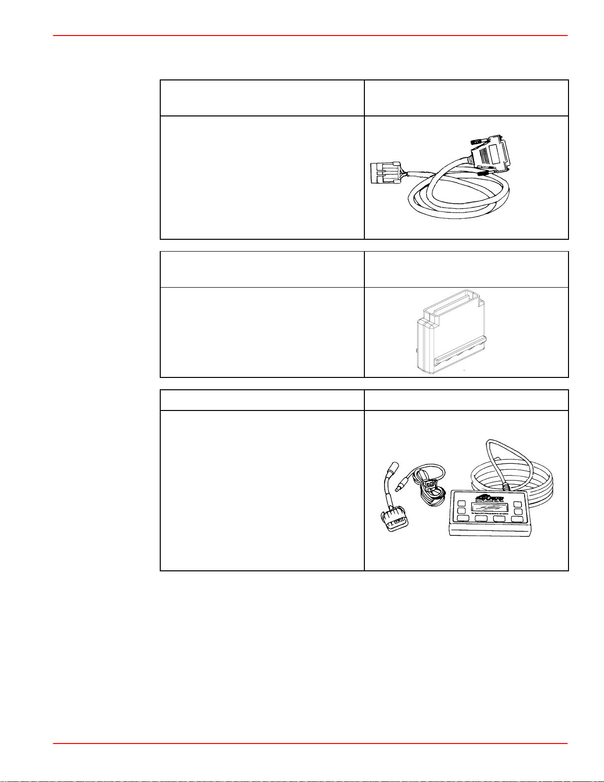
Harness Assembly /
Diagnostic Tester
Description:
25-pin to 4-pin Adaptor harness. For
PCM 555 and ECM 555 models (4-pin
connectors, no additional harness
required).
Mercury MerCruiser DDT
Cartridge Version 1.2
Description:
Use on PCM 555 and ECM 555 models.
91-822560A13
74214
91-880118A2
78036
Scan Tool Kit / Version 4.0 Note in Description
Description:
Hand-held Scan Tool updated for 2001.
(refer to Service Bulletin 2001-1). Use
with models:
MCM/MIE EFI (TBI) and MPI Gasoline
MCM/MIE 496/8.1S MPI PCM 555
1997 and Newer MCM/MIE Carbureted
Models with Thunderbolt Ignition System
MCM/MIE D-Tronic Diesel
NOTE: Tool must be ordered from Rinda
Technologies, Inc.
72428
90-864573 FEBRUARY 2002 Page 1A-7
Page 17
GENERAL INFORMATION SERVICE MANUAL NUMBER 36
Special Tools (continued)
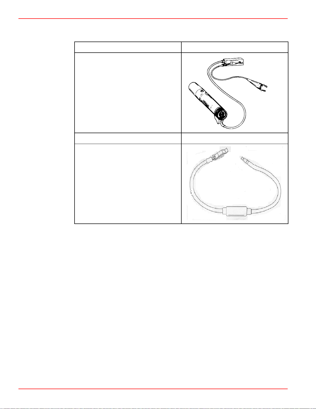
Portable Timing Light 91-99379
Description:
Checks the ignition timing, powered by 2
D-cell batteries.
73664
Spark Gap Tester 91-63998A1
Description:
Spark Gap Tester
Page 1A-8 90-864573 FEBRUARY 2002
Page 18

SERVICE MANUAL NUMBER 36
Special Tools (continued)
GENERAL INFORMATION
Rinda Technologies
4563 N. Elston Ave.
Chicago, IL 60630
Phone: 773-736-6633
Fax: 773-736-2950
Email: [email protected]
Mercury Marine
W6250 Pioneer Road,
P.O. Box 1929
Fond Du Lac, WI 54935-1939
Phone: 920-929-5589,
800-487-8736
www.MERCUR YMARINE.com
OTC
28635 Mound Rd.
Warren, MI 48092-3499
Phone: 586-574-2332,
800-328-6657
www.servicesolutions.spx.com
90-864573 FEBRUARY 2002 Page 1A-9
Page 19
GENERAL INFORMATION SERVICE MANUAL NUMBER 36
Precautions
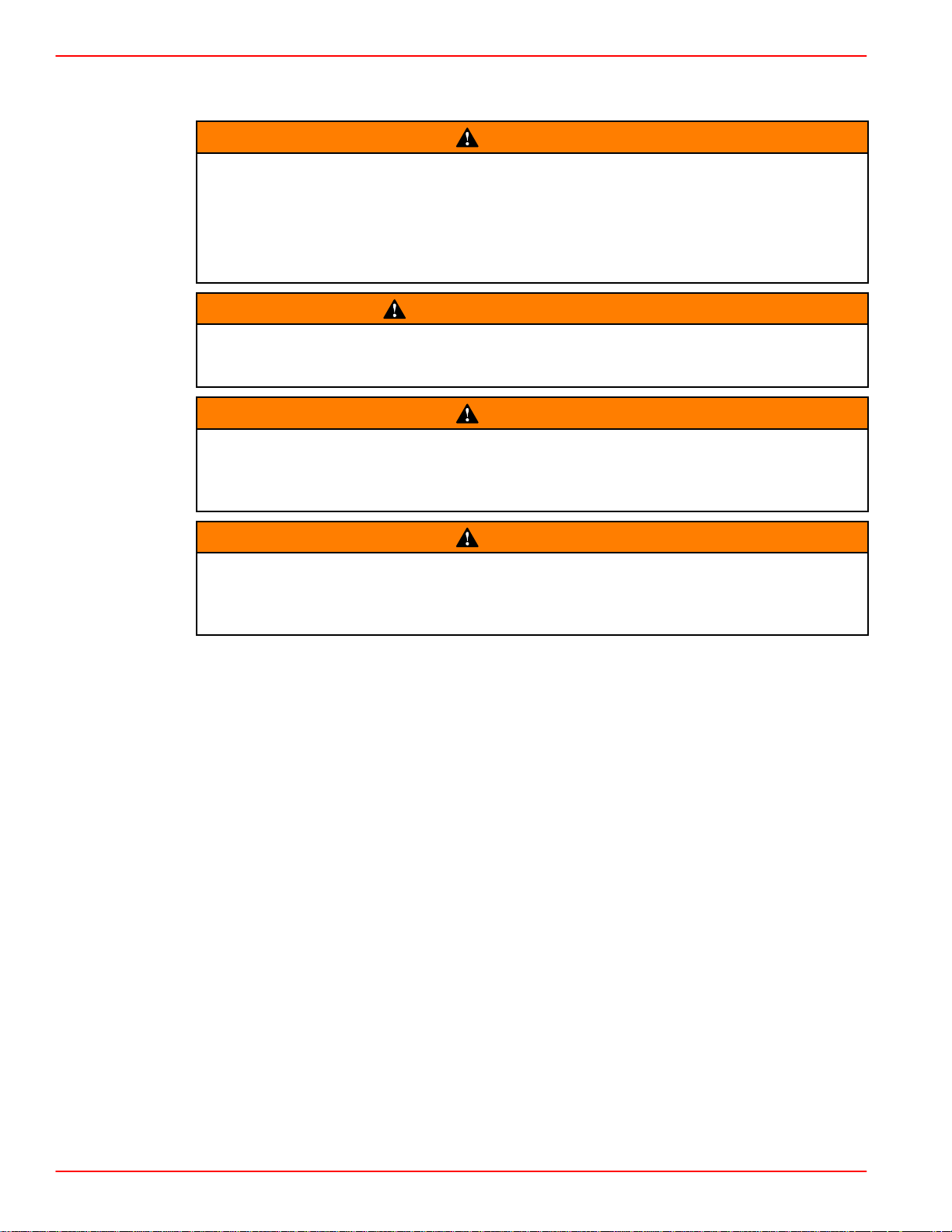
WARNING
Electrical, ignition and fuel system components on your Mercury MerCruiser are
designed and manufactured to comply with U.S. Coast Guard Rules and Regulations to minimize risks of fire and explosion.
Use of replacement electrical, ignition or fuel system components, which do not
comply with these rules and regulations, could result in a fire or explosion hazard
and should be avoided.
WARNING
Avoid injury or death and power package damage from an electrical shock, fire or
explosion. Always disconnect both battery cables from the battery before servicing
the power package.
WARNING
Be careful when cleaning flame arrestor and crankcase ventilation hose; gasoline
is extremely flammable and highly explosive under certain conditions. Ensure that
ignition key is OFF. Do NOT smoke or allow sources of spark or open flame in area
when cleaning flame arrestor and crankcase ventilation hose.
WARNING
Be careful when changing fuel system components; gasoline is extremely flammable and highly explosive under certain conditions. Ensure that ignition key is
OFF. DO NOT smoke or allow sources of spark or flame in the area while changing
fuel filter. Wipe up any spilled fuel immediately.
Page 1A-10 90-864573 FEBRUARY 2002
Page 20
SERVICE MANUAL NUMBER 36
Precautions (continued)
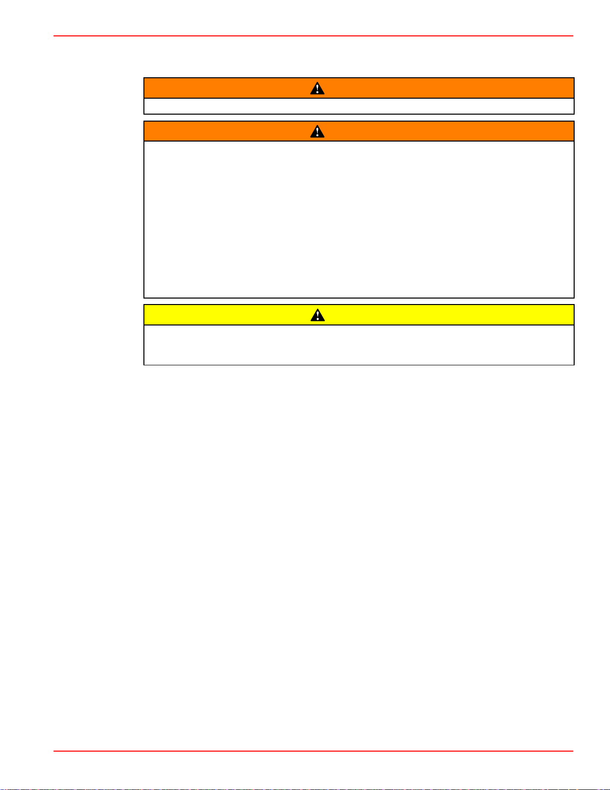
Make sure no fuel leaks exist, before closing engine hatch.
Avoid gasoline fire or explosion. Improper installation of brass fittings or plugs into
fuel pump or fuel filter base can crack casting and/or cause a fuel leak.
Apply Loctite 565 Pipe Sealant with T eflon to threads of brass fitting or plug. Do
NOT USE TEFLON TAPE.
Thread brass fitting or plug into fuel pump or fuel filter base until finger-tight.
Tighten fitting or plug an additional 1-3/4 to 2-1/4 turns using a wrench. Do NOT
OVERTIGHTEN.
Install fuel line. To prevent overtightening, hold brass fitting with suitable
wrench and tighten fuel line connectors securely.
Check for fuel leaks.
GENERAL INFORMATION
WARNING
WARNING
CAUTION
Overheating from insufficient cooling water will cause engine and drive system
damage. Ensure that there is sufficient water always available at water inlet holes
during operation.
90-864573 FEBRUARY 2002 Page 1A -11
 Loading...