

Page 1
CA741
Warranty Message
The product you have purchased comes with a limited warranty from Mercury Marine; the
terms of the warranty are set forth in the Warranty Sections of this manual. The warranty state-
ment contains a description of what is covered, what is not covered, the duration of coverage,
how to best obtain warranty coverage, important disclaimers and limitations of damages,
and other related information. Please review this important information.
CE344
WARNING
The operator (driver) is responsible for the correct and safe operation of the boat, the
equipment aboard and the safety of all occupants aboard. We strongly recommend
that the operator read this Operation, Maintenance and Warranty Manual and
thoroughly understand the operational instructions for the power package and all
related accessories before the boat is used.
WARNING
CALIFORNIA
PROPOSITION 65 WARNING
Diesel engine exhaust and some of its constituents are known to the state of
California to cause cancer, birth defects, and other reproductive harm.
The description and specifications contained herein were in effect at the time this guide was
approved for printing. Mercury Marine, whose policy is one of continuous improvement,
reserves the right to discontinue models at any time, or to change specifications or designs,
without notice and without incurring obligation.
1999, Mercury Marine
The following are registered trademarks of Brunswick Corporation:
Autoblend, Jet-Prop, Mariner, Merc, MerCathode, MerCruiser,
Mercury, Mercury Marine, Quicksilver, Ride-Guide, and Thruster.
Diesel Engines - Bravo Models
Mercury Marine Fond du Lac, Wisconsin, U.S.A.
Printed in U.S.A.
1999, Mercury Marine 90Ć860094990 1099
Page 2

CA753
WELCOME!
Y ou have selected one of the finest marine power packages available. It incorporates numerous design features
to assure operating ease and durability.
With proper care and maintenance, you will thoroughly enjoy using this product for many boating seasons. To
ensure maximum performance and carefree use, we ask that you thoroughly read this manual.
The Operation, Maintenance and Warranty Manual contains specific instructions for using and maintaining your
product. We suggest that this manual remain with the product for ready reference whenever you are on the water .
Thank you for purchasing one of our MerCruiser products. We sincerely hope your boating will be pleasant!
CONSUMER AFFAIRS DEPARTMENT
2
Page 3
CD474
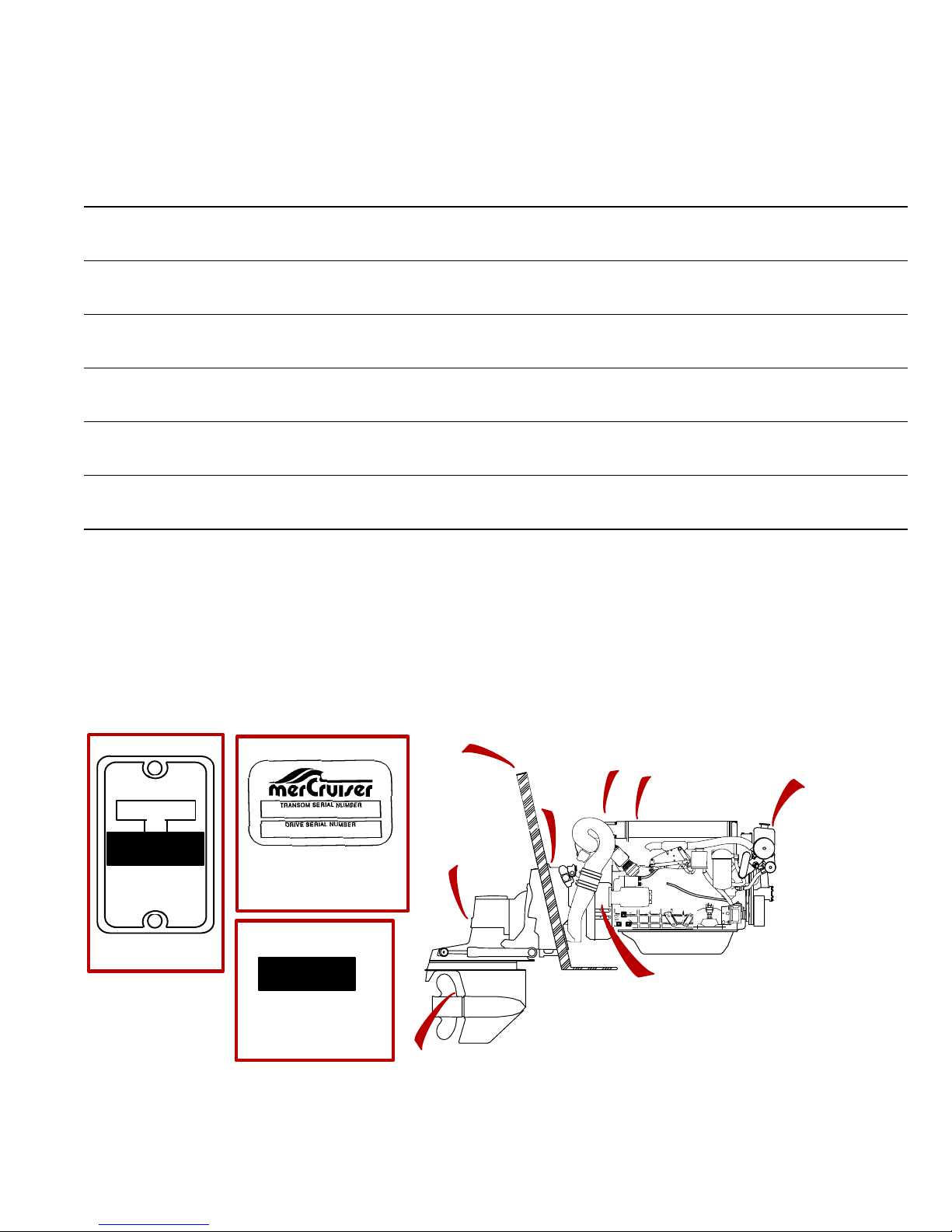
Identification Record
Please record the following information:
1
Engine Model and Horsepower
2
Transom Assembly Serial Number (Sterndrive)
3
Transmission Model (Inboard)
4
Propeller Number
5
Hull Identification Number (HIN)
6
Boat Manufacturer
7
Exhaust Gas Emissions Certificate Number (Europe Only)
Serial Numbers
Engine Serial Number
Gear Ratio Sterndrive Unit Serial Number
Gear Ratio Transmission Serial Number
Pitch Diameter
Purchase Date
Boat Model Length
The serial numbers are the manufacturer’s keys to numerous engineering details which apply to your
MerCruiser power package. When contacting your Authorized MerCruiser Dealer about service, always
specify model and serial numbers.
5
7
SERIAL NUMBER
BSO/SAV
1
2
7 (D-Tronic)
2
BRUNSWICK CORP.
FOND DU LAC,WIS.
54935 U.S.A.
1
71935
1
73929
BSO/SAV
1
7
4
74298
3
Page 4

CD673
TABLE OF CONTENTS
Page
Warranty Message 1. . . . . . . . . . . . . . . . . . . . . . . . . . . . . . . . . . . . . . . . . . . . . . . . . . . . . . . . . . . . . . . . . . . . . . . .
WELCOME! 2. . . . . . . . . . . . . . . . . . . . . . . . . . . . . . . . . . . . . . . . . . . . . . . . . . . . . . . . . . . . . . . . . . . . . . . . . . . . . . .
Identification Record 3. . . . . . . . . . . . . . . . . . . . . . . . . . . . . . . . . . . . . . . . . . . . . . . . . . . . . . . . . . . . . . . . . . . . . . . .
Table Of Contents 4. . . . . . . . . . . . . . . . . . . . . . . . . . . . . . . . . . . . . . . . . . . . . . . . . . . . . . . . . . . . . . . . . . . . . . . . . .
Warranty Information 6
Owner Warranty Registration 6. . . . . . . . . . . . . . . . . . . . . . . . . . . . . . . . . . . . . . . . . . . . . . . . . . . . . . . . . . . . . . . . .
International Owner Registration 7. . . . . . . . . . . . . . . . . . . . . . . . . . . . . . . . . . . . . . . . . . . . . . . . . . . . . . . . . . . . .
Mercruiser Diesel Limited Warranty 8. . . . . . . . . . . . . . . . . . . . . . . . . . . . . . . . . . . . . . . . . . . . . . . . . . . . . . . . .
Warranty Coverage and Exclusion 10. . . . . . . . . . . . . . . . . . . . . . . . . . . . . . . . . . . . . . . . . . . . . . . . . . . . . . . . .
Transferable Warranty 11. . . . . . . . . . . . . . . . . . . . . . . . . . . . . . . . . . . . . . . . . . . . . . . . . . . . . . . . . . . . . . . . . . . .
Read This Manual Thoroughly 13
General Information 14
Lanyard Stop Switch 14. . . . . . . . . . . . . . . . . . . . . . . . . . . . . . . . . . . . . . . . . . . . . . . . . . . . . . . . . . . . . . . . . . . . . . .
Exhaust Emissions 17. . . . . . . . . . . . . . . . . . . . . . . . . . . . . . . . . . . . . . . . . . . . . . . . . . . . . . . . . . . . . . . . . . . . . . . .
Wave And Wake Jumping 18. . . . . . . . . . . . . . . . . . . . . . . . . . . . . . . . . . . . . . . . . . . . . . . . . . . . . . . . . . . . . . . . . .
Impact With Underwater Hazards 19. . . . . . . . . . . . . . . . . . . . . . . . . . . . . . . . . . . . . . . . . . . . . . . . . . . . . . . . . . . .
Safe Boating Suggestions 20. . . . . . . . . . . . . . . . . . . . . . . . . . . . . . . . . . . . . . . . . . . . . . . . . . . . . . . . . . . . . . . . . .
Protecting People In The Water 21. . . . . . . . . . . . . . . . . . . . . . . . . . . . . . . . . . . . . . . . . . . . . . . . . . . . . . . . . . . . .
High-Speed And High-Performance Boat Operation 21. . . . . . . . . . . . . . . . . . . . . . . . . . . . . . . . . . . . . . . . . . . .
Conditions Affecting Operation 22
Weight Distribution 22. . . . . . . . . . . . . . . . . . . . . . . . . . . . . . . . . . . . . . . . . . . . . . . . . . . . . . . . . . . . . . . . . . . . . . . . .
Bottom Of Boat 22. . . . . . . . . . . . . . . . . . . . . . . . . . . . . . . . . . . . . . . . . . . . . . . . . . . . . . . . . . . . . . . . . . . . . . . . . . . .
Cavitation 22. . . . . . . . . . . . . . . . . . . . . . . . . . . . . . . . . . . . . . . . . . . . . . . . . . . . . . . . . . . . . . . . . . . . . . . . . . . . . . . .
Ventilation 22. . . . . . . . . . . . . . . . . . . . . . . . . . . . . . . . . . . . . . . . . . . . . . . . . . . . . . . . . . . . . . . . . . . . . . . . . . . . . . . .
Propeller Selection 23. . . . . . . . . . . . . . . . . . . . . . . . . . . . . . . . . . . . . . . . . . . . . . . . . . . . . . . . . . . . . . . . . . . . . . . .
How Elevation And Climate Affect Performance 24. . . . . . . . . . . . . . . . . . . . . . . . . . . . . . . . . . . . . . . . . . . . . . .
Important Information 25
Operation and Maintenance 25. . . . . . . . . . . . . . . . . . . . . . . . . . . . . . . . . . . . . . . . . . . . . . . . . . . . . . . . . . . . . . . .
Freezing Temperature And Cold Weather Operation 27. . . . . . . . . . . . . . . . . . . . . . . . . . . . . . . . . . . . . . . . . . .
Drain Plug and Bilge Pump 27. . . . . . . . . . . . . . . . . . . . . . . . . . . . . . . . . . . . . . . . . . . . . . . . . . . . . . . . . . . . . . . . .
Drive Unit Impact Protection 27. . . . . . . . . . . . . . . . . . . . . . . . . . . . . . . . . . . . . . . . . . . . . . . . . . . . . . . . . . . . . . . .
Launching and Boat Operation Care 28. . . . . . . . . . . . . . . . . . . . . . . . . . . . . . . . . . . . . . . . . . . . . . . . . . . . . . . . .
Attention Required After Submersion 28. . . . . . . . . . . . . . . . . . . . . . . . . . . . . . . . . . . . . . . . . . . . . . . . . . . . . . . . .
Trailering Boat 28. . . . . . . . . . . . . . . . . . . . . . . . . . . . . . . . . . . . . . . . . . . . . . . . . . . . . . . . . . . . . . . . . . . . . . . . . . . .
Stolen Power Package 28. . . . . . . . . . . . . . . . . . . . . . . . . . . . . . . . . . . . . . . . . . . . . . . . . . . . . . . . . . . . . . . . . . . . .
Replacement Service Parts 28. . . . . . . . . . . . . . . . . . . . . . . . . . . . . . . . . . . . . . . . . . . . . . . . . . . . . . . . . . . . . . . . .
Do-It-Yourself Maintenance Suggestions 29. . . . . . . . . . . . . . . . . . . . . . . . . . . . . . . . . . . . . . . . . . . . . . . . . . . . .
Diagnosing EDI Problems (If So Equipped) 30. . . . . . . . . . . . . . . . . . . . . . . . . . . . . . . . . . . . . . . . . . . . . . . . . . .
Multiple EDI Engine Battery Precautions 30. . . . . . . . . . . . . . . . . . . . . . . . . . . . . . . . . . . . . . . . . . . . . . . . . . . . . .
Engine Break-In 31. . . . . . . . . . . . . . . . . . . . . . . . . . . . . . . . . . . . . . . . . . . . . . . . . . . . . . . . . . . . . . . . . . . . . . . . . . .
Sterndrive Unit 10-Hour Break-In Period 32. . . . . . . . . . . . . . . . . . . . . . . . . . . . . . . . . . . . . . . . . . . . . . . . . . . . . .
After Break-In Period 32. . . . . . . . . . . . . . . . . . . . . . . . . . . . . . . . . . . . . . . . . . . . . . . . . . . . . . . . . . . . . . . . . . . . . . .
End of First Season Checkup 32. . . . . . . . . . . . . . . . . . . . . . . . . . . . . . . . . . . . . . . . . . . . . . . . . . . . . . . . . . . . . . .
100 Hour Checkup 32. . . . . . . . . . . . . . . . . . . . . . . . . . . . . . . . . . . . . . . . . . . . . . . . . . . . . . . . . . . . . . . . . . . . . . . . .
Operation 35
Quicksilver Instruments and Instrumentation 35. . . . . . . . . . . . . . . . . . . . . . . . . . . . . . . . . . . . . . . . . . . . . . . . . .
Electrical System Overload Protection 37. . . . . . . . . . . . . . . . . . . . . . . . . . . . . . . . . . . . . . . . . . . . . . . . . . . . . . . .
MerCathode System 37. . . . . . . . . . . . . . . . . . . . . . . . . . . . . . . . . . . . . . . . . . . . . . . . . . . . . . . . . . . . . . . . . . . . . . .
4
Page 5

Remote Controls 39. . . . . . . . . . . . . . . . . . . . . . . . . . . . . . . . . . . . . . . . . . . . . . . . . . . . . . . . . . . . . . . . . . . . . . . . . .
Power Trim 43. . . . . . . . . . . . . . . . . . . . . . . . . . . . . . . . . . . . . . . . . . . . . . . . . . . . . . . . . . . . . . . . . . . . . . . . . . . . . . .
Starting, Shifting and Stopping - D3.6L, D4.2L and D4.2L LD 49. . . . . . . . . . . . . . . . . . . . . . . . . . . . . . . . . . .
Operation Chart - D3.6L, D4.2L and D4.2L LD 52. . . . . . . . . . . . . . . . . . . . . . . . . . . . . . . . . . . . . . . . . . . . . . . .
Starting, Shifting and Stopping - D2.8L D-Tronic and D4.2L D-Tronic 53. . . . . . . . . . . . . . . . . . . . . . . . . . . . .
Operation Chart - D2.8L D-Tronic and D4.2L D-Tronic 56. . . . . . . . . . . . . . . . . . . . . . . . . . . . . . . . . . . . . . . . . .
Specifications 57
Seacock 57. . . . . . . . . . . . . . . . . . . . . . . . . . . . . . . . . . . . . . . . . . . . . . . . . . . . . . . . . . . . . . . . . . . . . . . . . . . . . . . . . .
Seawater Strainer 57. . . . . . . . . . . . . . . . . . . . . . . . . . . . . . . . . . . . . . . . . . . . . . . . . . . . . . . . . . . . . . . . . . . . . . . . .
Anti-Freeze/Coolant 57. . . . . . . . . . . . . . . . . . . . . . . . . . . . . . . . . . . . . . . . . . . . . . . . . . . . . . . . . . . . . . . . . . . . . . .
Fuel Requirements 58. . . . . . . . . . . . . . . . . . . . . . . . . . . . . . . . . . . . . . . . . . . . . . . . . . . . . . . . . . . . . . . . . . . . . . . .
Diesel Fuel In Cold Weather 59. . . . . . . . . . . . . . . . . . . . . . . . . . . . . . . . . . . . . . . . . . . . . . . . . . . . . . . . . . . . . . . .
Crankcase Oil 59. . . . . . . . . . . . . . . . . . . . . . . . . . . . . . . . . . . . . . . . . . . . . . . . . . . . . . . . . . . . . . . . . . . . . . . . . . . . .
Engine Specifications 60. . . . . . . . . . . . . . . . . . . . . . . . . . . . . . . . . . . . . . . . . . . . . . . . . . . . . . . . . . . . . . . . . . . . . .
Fluid Capacities 63. . . . . . . . . . . . . . . . . . . . . . . . . . . . . . . . . . . . . . . . . . . . . . . . . . . . . . . . . . . . . . . . . . . . . . . . . . .
Maintenance 64
General Information 64. . . . . . . . . . . . . . . . . . . . . . . . . . . . . . . . . . . . . . . . . . . . . . . . . . . . . . . . . . . . . . . . . . . . . . . .
Maintenance Aids 64. . . . . . . . . . . . . . . . . . . . . . . . . . . . . . . . . . . . . . . . . . . . . . . . . . . . . . . . . . . . . . . . . . . . . . . . .
Maintenance Schedules 65. . . . . . . . . . . . . . . . . . . . . . . . . . . . . . . . . . . . . . . . . . . . . . . . . . . . . . . . . . . . . . . . . . . .
Routine Maintenance 65. . . . . . . . . . . . . . . . . . . . . . . . . . . . . . . . . . . . . . . . . . . . . . . . . . . . . . . . . . . . . . . . . . . . . .
Scheduled Maintenance 66. . . . . . . . . . . . . . . . . . . . . . . . . . . . . . . . . . . . . . . . . . . . . . . . . . . . . . . . . . . . . . . . . . . .
Checking Fluid Levels 69. . . . . . . . . . . . . . . . . . . . . . . . . . . . . . . . . . . . . . . . . . . . . . . . . . . . . . . . . . . . . . . . . . . . . .
Changing Fluids 73. . . . . . . . . . . . . . . . . . . . . . . . . . . . . . . . . . . . . . . . . . . . . . . . . . . . . . . . . . . . . . . . . . . . . . . . . . .
Air Filter Cleaning/Replacement 79. . . . . . . . . . . . . . . . . . . . . . . . . . . . . . . . . . . . . . . . . . . . . . . . . . . . . . . . . . . . .
Drive Belts - All Engines, Except D3.6L Engines 79. . . . . . . . . . . . . . . . . . . . . . . . . . . . . . . . . . . . . . . . . . . . . . .
Drive Belts - D3.6L Engines 81. . . . . . . . . . . . . . . . . . . . . . . . . . . . . . . . . . . . . . . . . . . . . . . . . . . . . . . . . . . . . . . . .
Lubrication 83. . . . . . . . . . . . . . . . . . . . . . . . . . . . . . . . . . . . . . . . . . . . . . . . . . . . . . . . . . . . . . . . . . . . . . . . . . . . . . . .
Shift Cable 83. . . . . . . . . . . . . . . . . . . . . . . . . . . . . . . . . . . . . . . . . . . . . . . . . . . . . . . . . . . . . . . . . . . . . . . . . . . . . . . .
Cleaning Quicksilver Seawater Strainer 85. . . . . . . . . . . . . . . . . . . . . . . . . . . . . . . . . . . . . . . . . . . . . . . . . . . . . .
Flushing Seawater Cooling System 85. . . . . . . . . . . . . . . . . . . . . . . . . . . . . . . . . . . . . . . . . . . . . . . . . . . . . . . . . .
Fuel System 87. . . . . . . . . . . . . . . . . . . . . . . . . . . . . . . . . . . . . . . . . . . . . . . . . . . . . . . . . . . . . . . . . . . . . . . . . . . . . .
Seawater Pump Impeller 93. . . . . . . . . . . . . . . . . . . . . . . . . . . . . . . . . . . . . . . . . . . . . . . . . . . . . . . . . . . . . . . . . . .
Propellers (Bravo One and Two) 93. . . . . . . . . . . . . . . . . . . . . . . . . . . . . . . . . . . . . . . . . . . . . . . . . . . . . . . . . . . . .
Corrosion And Corrosion Protection 99. . . . . . . . . . . . . . . . . . . . . . . . . . . . . . . . . . . . . . . . . . . . . . . . . . . . . . . . . .
Battery 105. . . . . . . . . . . . . . . . . . . . . . . . . . . . . . . . . . . . . . . . . . . . . . . . . . . . . . . . . . . . . . . . . . . . . . . . . . . . . . . . . .
Bottom Of Boat 105. . . . . . . . . . . . . . . . . . . . . . . . . . . . . . . . . . . . . . . . . . . . . . . . . . . . . . . . . . . . . . . . . . . . . . . . . . .
Cold Weather or Extended Storage 107
Battery Winter Storage 107. . . . . . . . . . . . . . . . . . . . . . . . . . . . . . . . . . . . . . . . . . . . . . . . . . . . . . . . . . . . . . . . . . . .
Power Package Layup 107. . . . . . . . . . . . . . . . . . . . . . . . . . . . . . . . . . . . . . . . . . . . . . . . . . . . . . . . . . . . . . . . . . . .
Draining Instructions 109. . . . . . . . . . . . . . . . . . . . . . . . . . . . . . . . . . . . . . . . . . . . . . . . . . . . . . . . . . . . . . . . . . .
Power Package Recommissioning 113. . . . . . . . . . . . . . . . . . . . . . . . . . . . . . . . . . . . . . . . . . . . . . . . . . . . . . . . . .
Troubleshooting 114
Owner Service Assistance 120
Local Repair Service 120. . . . . . . . . . . . . . . . . . . . . . . . . . . . . . . . . . . . . . . . . . . . . . . . . . . . . . . . . . . . . . . . . . . . . .
Service Away From Home 120. . . . . . . . . . . . . . . . . . . . . . . . . . . . . . . . . . . . . . . . . . . . . . . . . . . . . . . . . . . . . . . . .
Parts And Accessories Inquiries 120. . . . . . . . . . . . . . . . . . . . . . . . . . . . . . . . . . . . . . . . . . . . . . . . . . . . . . . . . . . .
Resolving A Problem 120. . . . . . . . . . . . . . . . . . . . . . . . . . . . . . . . . . . . . . . . . . . . . . . . . . . . . . . . . . . . . . . . . . . . . .
Mercury Marine Service Offices 121. . . . . . . . . . . . . . . . . . . . . . . . . . . . . . . . . . . . . . . . . . . . . . . . . . . . . . . . . . . .
Customer Service Literature 122. . . . . . . . . . . . . . . . . . . . . . . . . . . . . . . . . . . . . . . . . . . . . . . . . . . . . . . . . . . . . . .
Ordering Literature 124. . . . . . . . . . . . . . . . . . . . . . . . . . . . . . . . . . . . . . . . . . . . . . . . . . . . . . . . . . . . . . . . . . . . . . .
Owner’s Logbook 125
5
Page 6

CD54
Warranty Information
CD55
Owner Warranty Registration
UNITED STATES AND CANADA ONLY
• It is important that your selling dealer fills out the Warranty Registration Card completely and mails it to the
factory immediately upon sale of the new product.
• It identifies name and address of the original purchaser, product model and serial number(s), date of sale,
type of use and selling dealer’s code, name and address. The dealer also certifies that you are the original
purchaser and user of the product.
• Upon receipt of the Warranty Registration Card at the factory, you will be issued a plastic Owner Warranty
Registration Card which is your only valid registration identification. It must be presented to the servicing dealer should warranty service be required. Warranty claims will not be accepted without presentation of this card.
• A temporary Owner Warranty Registration Card will be presented to you when you purchase the product It
is valid only for 30 days from date of sale while your plastic Owner Warranty Registration Card is being processed Should your product need service during this period, present the temporary registration card to the
dealer. He will attach it to your warranty claim form.
• Because of your selling dealer’s continuing personal interest in your satisfaction, the product should be re-
turned to him for warranty service.
• If your plastic card is not received within 30 days from date of new product sale, please contact your selling
dealer.
• The product warranty is not effective until the product is registered at the factory.
• NOTICE: Registration lists must be maintained by factory and dealer on marine products sold in the United
States, should notification under the federal boat safety act be required.
6
Page 7

CD56
International Owner Registration
OUTSIDE THE UNITED STATES AND CANADA
• It is important that your selling dealer fills out the Warranty Registration Card completely and mails it to the
distributor or Marine Power Service Center responsible for administering the warranty registration/claim program for your area.
• The W arranty Registration Card identifies your name and address, product model and serial number(s), date
of sale, type of use and the selling distributors/dealer’s code number , name and address. The distributor/dealer also certifies that you are the original purchaser and user of the product.
• A copy of the Warranty Registration Card, designated as the “Purchaser’s Copy”, MUST be given to you im-
mediately after the card has been completely filled out by the selling distributor/dealer . This card represents
your factory registration identification, and should be retained by you for future use when required Should you
ever require warranty service on this product, your dealer may ask you for the Warranty Registration Card
to verify date of purchase and to use the information on the card to prepare the warranty claim form(s).
• In some countries, the Marine Power Service Center will issue you a permanent (plastic) Warranty Registra-
tion Card within 30 days after receiving the “Factory Copy” of the Warranty Registration Card from your distributor/dealer If you receive a plastic Warranty Registration Card, you may discard the “Purchaser’s Copy” that
you received from the distributor/dealer when you purchased the product. Ask your distributor/dealer if this
plastic card program applies to you.
• For further information concerning the Warranty Registration Card and its relationship to Warranty Claim pro-
cessing, refer to the “International Warranty.” Refer to “Table of Contents.”
IMPORTANT: Registration lists must be maintained by the factory and dealer in some countries by law.
It is our desire to have ALL products registered at the factory should it ever be necessary to contact you.
Make sure your dealer/distributor fills out the warranty registration card immediately and sends the factory copy to the Marine Power International Service Center for your area.
7
Page 8

CD600
Warranty Policy
Mercruiser Diesel Limited Warranty
I. We warrant each new production MerCruiser Diesel Sterndrive Power Package, Inboard Engine and
Accessories attached thereto (hereafter referred to as “Product”), manufactured by MerCruiser
(hereafter referred to as the “Company”), to be free from defects in material and workmanship, but only
when the customer purchases or obtains predelivery service from a Dealer authorized by us to
distribute MerCruiser Product in the country in which the sale or predelivery service occurred. This
warranty shall apply only to pleasure craft and light-duty craft applications.
II. This warranty shall become effective upon the date of sale to the first purchaser or user of the Product.
The warranty period for Pleasure Craft applications is one (1) year from date of sale to the first
purchaser or user of the product. The warranty period for Light-Duty Craft applications is one (1) year
from date of sale to the first purchaser or user of the product, or the accumulation of 500 hours of engine
operation, whichever occurs first. For purposes of this warranty Pleasure Craft is defined as a
recreational planing craft used exclusively for pleasure and recreation. Light-Duty Craft is defined as
a planing hull vessel used in law enforcement, commercial, or professional entertainment activity, or
in an enterprise or venture in which revenue (in any amount) is generated directly or indirectly.
Light-Duty Craft is further defined as having an annual operating time not to exceed 500 hours,
Wide-Open-Throttle operation is limited to less that 10% of operating time, and continuous cruising
RPM is limited to at or less than 90% of Wide-Open-Throttle RPM. If the applicable law prohibits
limitation of warranty coverage to one (1) year, then the warranty shall be the minimum period required
by law. The unused period of the applicable warranty, i f a ny, is transferable to subsequent purchasers.
III. To validate the warranty, the “W arranty Registration Card”, included with each Product, must be prop-
erly completed by the selling dealer and forwarded immediately after the sale to Mercury Marine
(U.S.A. and Canada) or to a Marine Power International Branch, or Distributor Service Office (outside
the U.S.A. and Canada).
IV. Purchaser must provide proof of purchase and substantiate the original date of sale by presenting to
the dealer, authorized to service the Product, the original purchaser’s copy of the “Warranty
Registration Card” or the “Owner Warranty Registration Card”. If either of these items is not available,
purchaser must provide a copy of the original purchaser’s “Bill of Sale” (Sales Contract) for the Product
to be serviced. Warranty claims will not be accepted by the dealer until the original date of sale and
Product serial number can be verified.
V. It is a condition for the continuation of this warranty that the Product be taken to an authorized
MerCruiser Service Dealer, after 100 hours of engine operation, but not later than 150 hours, for
required checks and adjustments. A copy of the dealer service work order must be retained as
evidence of the completion of this requirement.
VI. Since this warranty applies to defects in material or workmanship, it does not apply to normal wear,
adjustments, tune-ups or to damage caused by: 1) Neglect, lack of maintenance, accident, abnormal
operation, improper installation or service; 2) Use of a propeller not properly suited to application/boat
load or, failure to follow instructions in applicable service and warranty information manuals or
operation and maintenance manual; 3) Use of an accessory or part not manufactured or sold by us;
4) Operation with fuels, oils, lubricants or coolants/coolant additives which are not suitable for use with
the Product or recommended by us; 5) Participating in or preparing for racing or other competitive
activity or operating with racing type lower unit; 6) Alteration or removal of parts; 7) Water entering
engine cylinder/s through the exhaust system or air intake system; 8) Use of product in a
full-displacement or semi-displacement hull vessel; or 9) Use or operation of the product in a manner
inconsistent with the “Recommended Operation/Duty Cycle” section of the Operation, Maintenance
and Warranty Manual.
8
Page 9

MerCruiser Diesel Limited Warranty (continued from previous page)
VII. Reasonable access must be provided to the Product for warranty service. This warranty will not apply
to: 1) Haul-out, launch, towing and storage charges, telephone or rental charges of any type, inconvenience, or loss of time or income, or other consequential damages; or 2) Removal and/or replacement
of boat partitions or material because of boat design for necessary access to the Product.
VIII. Claim shall be made under this warranty by delivering the Product for inspection to a MerCruiser dealer
authorized to service the Product. If purchaser cannot deliver Product to such authorized dealer, he
may give notice in writing to the Company (U.S.A. and Canada) or the nearest Marine Power International Branch or Distributor Service Office (outside the U.S.A. and Canada). We shall then arrange f or
the inspection and repair, provided such service is covered under this warranty. Purchaser shall pay
for all related transportation charges and/or travel time. If the service is not covered by this warranty,
purchaser shall pay for all related labor and material, and any other expenses associated with that
service. Any Product or parts shipped by purchaser for inspection or repair must be shipped with transportation charges prepaid.
IX. Our sole and exclusive obligation under this warranty shall be limited to repairing a defective part or,
at our option, refunding the purchase price or replacing such part or parts with new or Mercury certified
remanufactured parts as shall be necessary to remedy any malfunction resulting from defects in material or workmanship as covered by this warranty. The repair or replacement of parts, or the performance of service, under this warranty, does not extend the period of this warranty beyond its original
expiration date. We reserve the right to improve the design of any Product without assuming any obligation to modify any Product previously manufactured.
X. ALL INCIDENTAL AND/OR CONSEQUENTIAL DAMAGES ARE EXCLUDED FROM THIS
WARRANTY. WARRANTIES OF MERCHANTABILITY AND FITNESS ARE EXCLUDED FROM
THIS WARRANTY. IMPLIED WARRANTIES ARE LIMITED TO THE LIFE OF THIS WARRANTY.
SOME STATES OR COUNTRIES DO NOT ALLOW LIMITATIONS ON HOW LONG AN IMPLIED
WARRANTY LASTS OR THE EXCLUSION OR LIMITATION OF INCIDENTAL OR
CONSEQUENTIAL DAMAGES, SO THE ABOVE LIMITATION OR EXCLUSIONS MAY NOT APPLY
TO YOU.
XI. This warranty gives you specific legal rights and you may also have other legal rights which vary from
state to state and country to country.
9
Page 10

CD622
Warranty Coverage and Exclusion
Keep in mind that warranty covers repairs that are needed within the warranty period because of defects in material and workmanship. Installation errors, accidents normal wear and a variety of other causes that affect the
product are not covered.
Warranty is limited to defects in material or workmanship, but only when the consumer sale is made in the country
to which distribution is authorized by us.
Should you have any questions concerning warranty coverage contact your authorized dealer. They will be
pleased to answer any questions that you may have.
WARRANTY DOES NOT APPLY TO THE FOLLOWING:
• Minor adjustments or checks, including checking fuel injection pump timing, cleaning fuel injectors, filters, or
adjusting belts, controls, and checking lubrication made in connection with normal services.
• Damage caused by neglect, lack of maintenance, accident, abnormal operation, improper installation or ser-
vice, or freezing temperatures.
• Haul-out, launch, towing charges; removal and/or replacement of boat partitions or material because of boat
design for necessary access to the product; all related transportation charges and/or travel time, etc. Reasonable access must be provided to the product for warranty service. Customer must deliver product to an Authorized Dealer.
• Additional service work requested by customer other than that necessary to satisfy the warranty obligation.
• Labor performed by other than an Authorized Dealer may be covered only under following circumstances:
When performed on emergency basis (providing there are no Authorized Dealers in area who can perform
the work required or have no facilities to haul out, etc., and prior factory approval has been given to have the
work performed at this facility).
• All incidental and/or consequential damages (storage charges, telephone or rental charges of any type, in-
convenience or loss of time or income) are the owner’s responsibility.
• Use of other than Quicksilver replacement parts when making warranty repairs.
• Oils, lubricants or fluids changed as a matter of normal maintenance is customer’s responsibility unless loss
or contamination of same is caused by product failure that would be eligible for warranty consideration.
• Participating in or preparing for racing or other competitive activity.
• Engine noise does not necessarily indicate a serious engine problem. If diagnosis indicates a serious internal
engine condition which could result in a failure, condition responsible for noise should be corrected under the
warranty.
• Lower unit and/or propeller damage caused by striking a submerged object is considered a marine hazard.
• Water entering the engine via the air filter or exhaust system or submersion. Also, water in the starter motor.
• Starter motors and/or armatures or field coil assembly, which are burned, or where lead is thrown out of com-
mutator because of excess cranking.
• Valve or valve seat grinding required because wear.
• Failure of any parts caused by lack of cooling water, which results from starting power package out of water,
foreign material blocking inlets or power package being mounted too high.
• Use of fuels and lubricants which are not suitable for use with or on the product. Refer to your Operation and
Maintenance Manual.
• Our limited warranty does not apply to any damage to our products caused by the installation or use of parts
and accessories which are not manufactured or sold by us. Failures which are not related to the use of those
parts or accessories, are covered under warranty, if they otherwise meet the terms of the limited warranty for
that product.
10
Page 11

CE350
Transferable Warranty
The product warranty is transferable to a subsequent purchaser , but only for the remainder of the unused portion
of the limited warranty. This will not apply to products used for commercial applications.
DIRECT SALE BY OWNER
• The second owner can be registered as the new owner and retain the unused portion of the limited warranty
by sending the former owner’s plastic Owner W arranty Registration Card and a copy of the bill of sale to show
proof of ownership. In the United States and Canada, mail to:
Attn: Warranty Registration Department
Mercury Marine
W6250 West Pioneer Road
P.O. Box 1939
Fond du Lac, Wl 54936-1939
• A new Owner Warranty Registration Card will be issued with the new owner’s name and address. Registration
records will be changed on the factory computer registration file.
• There is no charge for this service.
Outside the United States and Canada, please contact the closest Mercury Marine Service Office, or the
closest distributor in your country, for the transferable warranty procedure that would apply to you.
11
Page 12

CD594
THIS PAGE IS INTENTIONALLY BLANK
12
Page 13
CD326
Read This Manual Thoroughly
IF YOU DON’T UNDERSTAND ANY PORTION, CONTACT YOUR DEALER FOR A DEMONSTRATION
OF ACTUAL STARTING AND OPERATING PROCEDURES.
NOTICE
Throughout this publication, and on your power package WARNINGS and CAUTIONS, accompanied by the In -
ternational HAZARD Symbol
ular service or operation that may be hazardous if performed incorrectly or carelessly . Observe them carefully.
These “Safety Alerts” alone cannot eliminate the hazards that they signal. Strict compliance with these special
instructions while performing the service, plus “common sense” operation, are major accident prevention measures.
Hazards or unsafe practices which could result in severe personal injury or death.
Hazards or unsafe practices which could result in minor personal injury or product or property
damage.
, may be used to alert the installer/user to special instructions concerning a partic-
!
WARNING
CAUTION
IMPORTANT: Indicates information or instructions that are necessary for proper operation and/or
maintenance.
WARNING
The operator (driver) is responsible for the correct and safe operation of the boat, the equipment
aboard and the safety of all occupants aboard. We strongly recommend that the operator read this
Operation and Maintenance Manual and thoroughly understand the operational instructions for the
power package and all related accessories before the boat is used.
We strongly recommend that other occupants be instructed on proper starting and operation
procedures so they will be prepared should they be required to operate the power package and boat
in an emergency.
WARNING
The use of accessories not manufactured or sold by Mercury Marine is not recommended for use with
your MerCruiser unit. If your MerCruiser unit is equipped with an accessory not manufactured by
Mercury Marine, be sure to read the Operation and Maintenance Manual for the accessory before
operation. If you haven’t been supplied with such a manual, contact your dealer or the manufacturer
of the accessory to secure the applicable manual.
Electrical system components on this engine are not external ignition protected. DO NOT STORE OR
UTILIZE GASOLINE ON BOATS EQUIPPED WITH THESE ENGINES, UNLESS PROVISIONS HAVE BEEN
MADE TO EXCLUDE GASOLINE VAPORS FROM ENGINE COMPARTMENT (REF: 33 CFR). Failure to
comply could result in fire, explosion and/or severe personal injury.
WARNING
13
Page 14
CA619
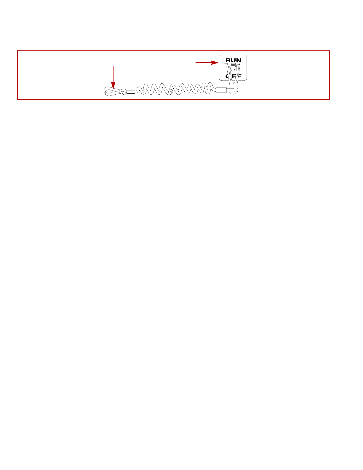
Lanyard Stop Switch
General Information
2
The purpose of a lanyard stop switch (1) is to turn off the engine when the operator moves far enough away from
the operator’s position (as in accidental ejection from the operator’s position) to activate the switch. Some remote
control units are equipped with a lanyard stop switch. A lanyard stop switch can be installed on the dashboard
or side adjacent to the operator’s position.
The lanyard is a cord usually between 4 and 5 feet (1220 and 1524 mm) in length when stretched out with an
element on one end made to be inserted into the switch and a snap (2) on the other end for attaching to the
operator. The lanyard is coiled to make its at-rest condition as short as possible so as to minimize the likelihood
of lanyard entanglement with nearby objects. It is made as long as it is in its stretched condition to minimize the
likelihood of accidental activation should the operator choose to move around in an area close to the normal
operator’s position. If it is desired to have a shorter lanyard, wrap the lanyard around the operator’s wrist or leg,
or tie a knot in the lanyard.
IMPORTANT: The purpose of a lanyard stop switch is to stop the engine when the operator moves far
enough away from the operator’s position to activate the switch. This would occur if the operator
accidentally falls overboard or moves within the boat a sufficient distance from the operator’s position.
Accidental ejections and falls overboard are more likely to occur in certain types of boats such as low
sided sport boats or bass boats, and high-performance boats. Accidental ejections and falls overboard
are also likely to occur as a result of poor operating practices such as sitting on the back of the seat or
gunwale at planing speeds, standing at planing speeds, sitting on elevated fishing boat decks, operating
at planing speeds in shallow or obstacle-infested waters, releasing your grip on a steering wheel that
is pulling in one direction, drinking alcohol or consuming drugs, or daring, high-speed boat maneuvers.
1
74608
14
Page 15

While activation of the lanyard stop switch will stop the engine immediately , a boat will continue to coast for some
distance depending upon the velocity and degree of any turn at shut-down. However, the boat will not complete
a full circle. While the boat is coasting, it can cause injury to anyone in the boat’s path as seriously as the boat
would when under power.
We strongly recommend that other occupants be instructed on proper starting and operating procedures should
they be required to operate the engine in an emergency (e.g. if the operator is accidentally ejected).
WARNING
Should the operator fall out of the boat, the possibility of serious injury or death from being run over
by the boat can be greatly reduced by stopping the engine immediately. Always properly connect both
ends of the stop switch lanyard to the stop switch and the operator.
Accidental or unintended activation of the switch during normal operation is also a possibility. This could cause
any, or all, of the following potentially hazardous situations:
1 Occupants could be thrown forward due to unexpected loss of forward motion – a particular concern for
passengers in the front of the boat who could be ejected over the bow and possibly struck by the gear case or
propeller.
2 Loss of power and directional control in heavy seas, strong current or high winds.
3 Loss of control when docking.
WARNING
Avoid serious injury or death from deceleration forces resulting from accidental or unintended stop
switch activation. The boat operator should never leave the operator’s station without first
disconnecting the stop switch lanyard from the operator.
15
Page 16
CA641
CA642
1
Courtesy of ABYC
2A
2B
3A
16
3B
Courtesy of ABYC
Page 17

CA620
Exhaust Emissions
BE ALERT TO CARBON MONOXIDE POISONING
Carbon monoxide is present in the exhaust fumes of all internal combustion engines including the outboards,
sterndrives and inboard engines that propel boats, as well as the generators that power various boat
accessories. Carbon monoxide is a deadly gas that is odorless, colorless and tasteless.
Early symptoms of carbon monoxide poisoning, which should not be confused with seasickness or intoxication,
include headache, dizziness, drowsiness, and nausea.
WARNING
Avoid the combination of a running engine and poor ventilation. Prolonged exposure to carbon
monoxide in sufficient concentration can lead to unconsciousness, brain damage or death.
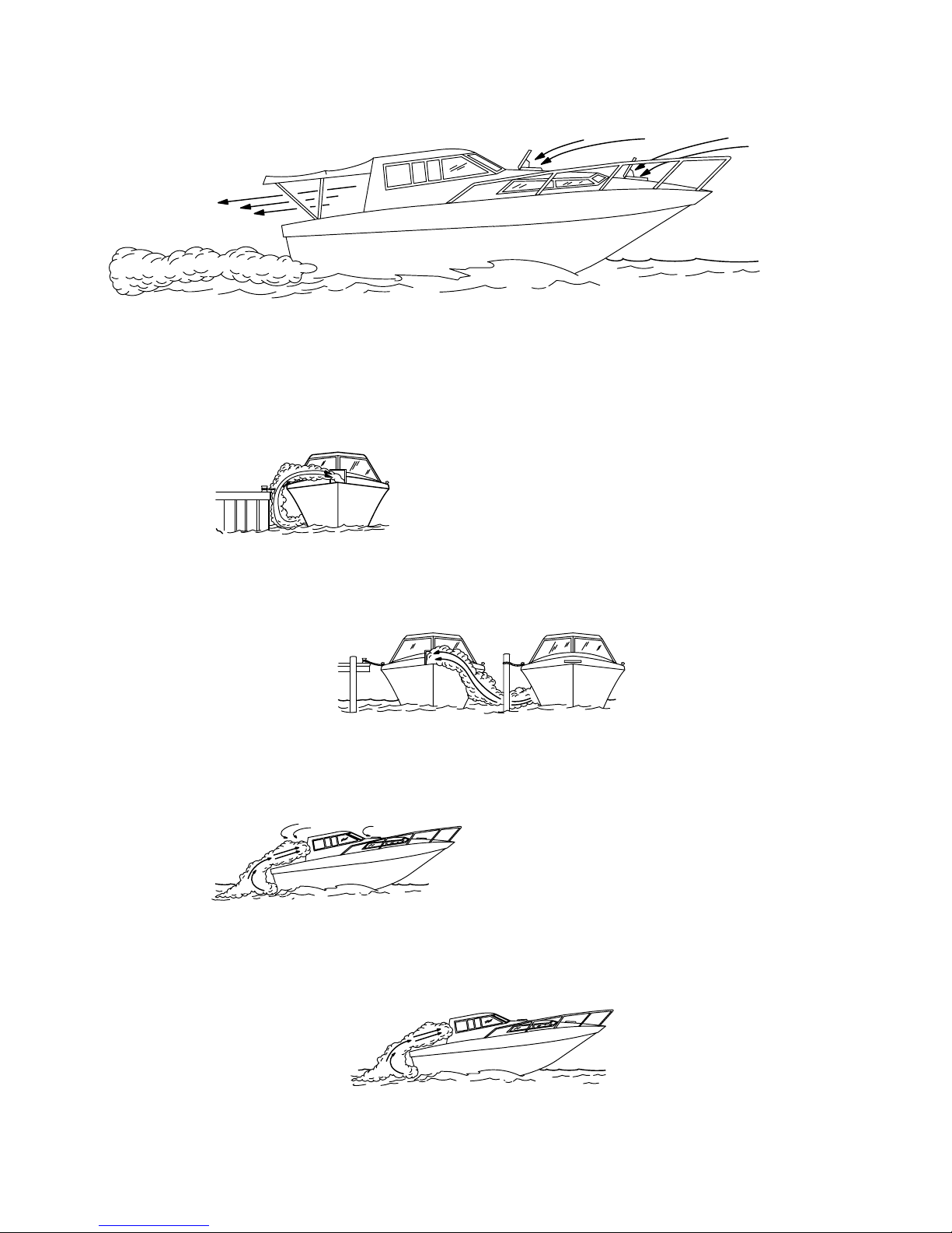
GOOD VENTILATION
Ventilate passenger area, open side curtains, or forward hatches to remove fumes.
1 Example of desired air flow through the boat.
CA643
POOR VENTILATION
Under certain running and/or wind conditions, permanently enclosed or canvas enclosed cabins or cockpits with
insufficient ventilation may draw in carbon monoxide. Install one or more carbon monoxide detectors in your
boat.
Although the occurrence is rare, on a very calm day, swimmers and passengers in an unclosed area of a
stationary boat that contains or is near a running engine may be exposed to a hazardous level of carbon
monoxide.
2 Examples of poor ventilation while boat is stationary:
A Running the engine when the boat is moored in a confined space.
B Mooring close to another boat that has its engine running.
3 Examples of poor ventilation while boat is moving:
A Running the boat with the trim angle of the bow too high.
B Running the boat with no forward hatches open (station wagon effect).
17
Page 18
CD543
Wave And Wake Jumping
Operating recreational boats over waves and wakes is a natural part of boating. However, when this activity is
done with speed to force the boat hull partially or completely out of the water, certain hazards arise, particularly
when the boat re-enters the water.
The primary concern is the boat changing direction while in the midst of the jump. In such case the landing may
cause the boat to violently veer in a new direction. Such a sharp change in direction or turn can cause occupants
to be thrown out of their seats or out of the boat.
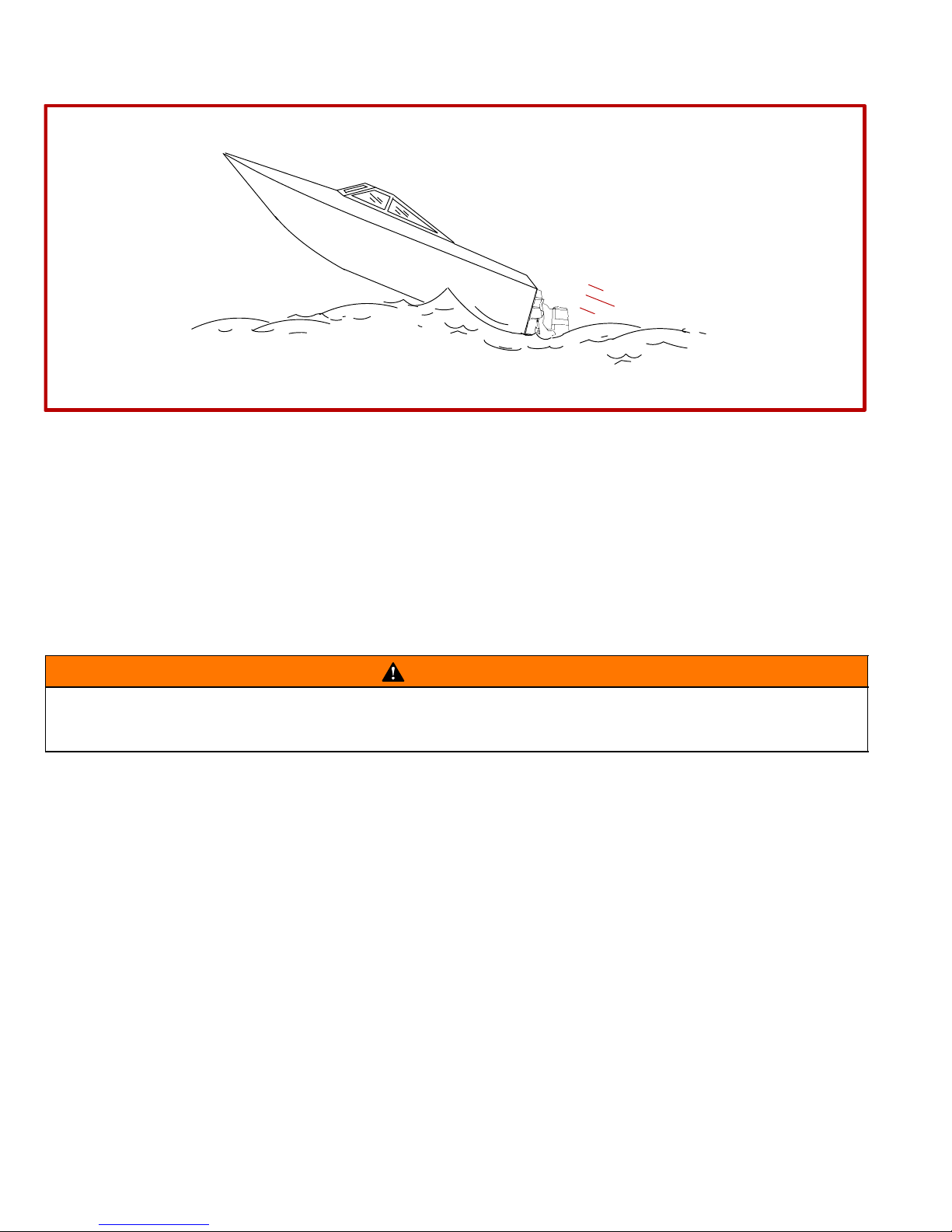
There is another less common hazardous result from allowing your boat to launch off a wave or wake. If the bow
of your boat pitches down far enough while airborne, upon water contact it may penetrate under the water surface
and “submarine” for an instant. This will bring the boat nearly to a stop in an instant and can send the occupants
flying forward. The boat may also steer sharply to one side.
WARNING
Avoid serious injury or death from being thrown within or out of a boat when it lands after jumping a
wave or wake. Avoid wave or wake jumping whenever possible. Instruct all occupants that if a wake
or wave jump occurs, get low and hang on to any boat hand hold.
18
Page 19
CD604
Impact With Underwater Hazards
Reduce speed and proceed with caution whenever you’re driving a boat in shallow water areas or in areas where
the waters are suspected of having underwater obstacles that could be struck by the sterndrive or the boat bottom. The most important thing you can do to help reduce injury or impact damage from striking a floating
or underwater object is control the boat speed. Under these conditions, boat speed should be kept to
a minimum planing speed of 15 to 25 mph (24 to 40 km/h).
Striking a floating/underwater object may result in an infinite number of situations. Some of these situations could
result in the following:
• The boat could move suddenly in a new direction. Such a sharp change in direction or turn can cause occu-
pants to be thrown out of their seats or out of the boat.
• A rapid reduction in speed. This will cause occupants to be thrown forward, even out of the boat.
• Impact damage to the sterndrive and/or boat.
Keep in mind, one of the most important things you can do to help reduce injury or impact damage in these situations is control the boat speed. Boat speed should be kept to a minimum planing speed when driving in waters
known to have underwater obstacles.
After striking a submerged object, stop engine as soon as possible and inspect the sterndrive unit for any broken
or loose parts. If damage is present or suspected, the power package should be taken to an authorized dealer
for a thorough inspection and necessary repair.
The boat should also be checked for any hull fractures, transom fractures, water leaks.
Operating a damaged sterndrive could cause additional damage to other parts of the power package, or could
affect control of the boat. If continued running is necessary, do so at greatly reduced speeds.
WARNING
Avoid serious injury or death from loss of boat control. Continued boating with major impact damage
can result in sudden component failure with or without subsequent impacts. Have the power package
thoroughly inspected and any necessary repairs made.
19
Page 20

CA476
Safe Boating Suggestions
In order to safely enjoy the waterways, familiarize yourself with local and other governmental boating regulations
and restrictions, and consider the following suggestions.
• Know and obey all nautical rules and laws of the waterways. Boat operators should complete a boating
safety course. Courses are offered in the U.S.A. by (1) The U.S. Coast Guard Auxiliary , (2) The Power Squadron, (3) The Red Cross and (4) your state or provincial boating law enforcement agency. Inquiries may be
made to the Boating Hotline, 1-800-368-5647 or the Boat U.S. Foundation information number
1-800-336-BOAT.
We strongly recommend that all powerboat operators attend one of these courses.
You should also review the NMMA Sources of Waterway Information booklet. It lists regional sources of safety,
cruising and local navigation and is available at no charge by writing to:
Sources of Waterway Information
National Marine Manufacturers Association
410 N. Michigan Avenue
Chicago, IL 60611 U.S.A.
• Perform safety checks and required maintenance. Follow a regular schedule and ensure that all repairs
are properly made.
• Check safety equipment on board. Here are suggestions of the types of safety equipment to carry when
boating:
(1) Approved fire extinguisher(s); paddle or oar.
(2) Signal devices: flashlight, rockets or flares, flag and whistle or horn.
(3) Spare propeller, thrust hubs and an appropriate wrench.
(4) Tools for necessary minor repairs; first aid kit and book.
(5) Anchor and extra anchor line; water-proof storage containers.
(6) Manual bilge pump and extra drain plugs; compass and map or chart of area.
(7) Spare operating equipment; batteries, bulbs, fuses, etc.
(8) Transistor radio
(9) Drinking water
• Know signs of weather change and avoid foul weather and rough-sea boating.
• Tell someone where you are going and when you expect to return.
• Passenger boarding. Stop the engine whenever passengers are boarding, unloading or are near the back
(stern) of the boat. Just shifting the drive unit into neutral is not sufficient.
• Use personal flotation devices. Federal Law requires that there be a U.S. Coast Guard approved, wear-
able-type life jacket (personal flotation device), correctly sized and readily accessible for every person on
board, plus a throwable cushion or ring. We strongly advise that everyone wear a life jacket at all times while
in the boat.
• Prepare other boat operators. Instruct at least one person on board in the basics of starting and operating
the engine and boat handling in case the driver becomes disabled or falls overboard.
• Do not overload your boat. Most boats are rated and certified for maximum load (weight) capacities (refer
to your boat capacity plate). When in doubt, contact your dealer or the boats manufacturer. Know your boat’s
operating and loading limitations.
• Make sure everyone in the boat is properly seated. Don’t allow anyone to sit or ride on any part of the boat
that was not intended for such use. This includes backs of seats, gunwales, transom, bow, decks, raised fishing
seats, any rotating fishing seat; anywhere that sudden unexpected acceleration, sudden stopping, unexpected
loss of boat control or sudden boat movement could cause a person to be thrown overboard or into the boat.
20
Page 21

• Never be under the influence of alcohol or drugs while boating (it is the law). They impair your judgment
and greatly reduce your ability to react quickly.
• Know your boating area and avoid hazardous locations.
• Be alert. The operator of the boat is responsible by law to “maintain a proper lookout by sight (and hearing).”
The operator must have an unobstructed view particularly to the front. No passengers, load, or fishing seats
should block the operators view when operating the boat above idle or planing transition speed. Watch “the
other guy,” the water and your wake.
• Never drive your boat directly behind a water skier in case the skier falls. As an example, your boat trav-
eling at 25 miles per hour (40 km/hr) in 5 seconds will overtake a fallen skier who was 200 feet in front of you.
• Watch fallen skiers. When using your boat for water skiing or similar activities, always keep a fallen or down
skier on the operator’s side of the boat while returning to attend the skier. The operator should always have
the down skier in sight and never back up to the skier or anyone in the water.
• Report accidents. Boat operators are required by law to file a Boating Accident Report with their state boat-
ing law enforcement agency when their boat is involved in certain boating accidents. A boating accident must
be reported if (1) there is loss of life or probable loss of life, (2) there is personal injury requiring medical treatment beyond first aid, (3) there is damage to boats or other property where the damage value exceeds
$500.00 or (4) there is complete loss of the boat. Seek further assistance from local law enforcement.
CA282
Protecting People In The Water
WHILE YOU ARE CRUISING
It is very difficult for a person standing or floating in the water to take quick action to avoid a boat heading in his/her
direction even at slow speed.
Always slow down and exercise extreme caution any time you are boating in an area where there might be people
in the water.
Whenever a boat is moving (coasting) and the drive unit is in neutral position, there is sufficient force by the water
on the propeller to cause the propeller to rotate. This neutral propeller rotation can cause serious injury.
WHILE BOAT IS STATIONARY
Shift the drive unit into neutral and shut off the engine before allowing people to swim or be in the water near
your boat.
WARNING
Stop your engine immediately whenever anyone in the water is near your boat. Serious injury to the
person in the water is likely if contacted by a rotating propeller, a moving boat, a moving gear case,
or any solid device rigidly attached to a moving boat or gear case.
CC828
High-Speed And High-Performance Boat Operation
If your boat is considered a high-speed or high-performance boat with which you are unfamiliar, we recommend
that you never operate it at its high speed capability without first requesting an initial orientation and
familiarization demonstration ride with your dealer or an operator experienced with your boat. For additional
information, obtain a copy of our “Hi-Performance Boat Operation” booklet (Part Number 90-849250--1) from
your dealer, distributor, or Mercury Marine.
21
Page 22

CA7
Conditions Affecting Operation
Weight Distribution
Positioning of weight (passengers and gear) inside the boat has the following effects:
A. Shifting weight to rear (stern) will:
• Generally increases speed and engine RPM.
• At extremes, can cause boat to porpoise.
• Causes bow to bounce in choppy water.
• Increases danger of following wave splashing into boat when coming off plane.
B. Shifting weight to front (bow) will:
• Improve ease of planing on some boats.
• Improve rough water ride.
• At extremes, can cause boat to veer back and forth (bow steer).
CA8
Bottom Of Boat
To maintain maximum speed, the following conditions of the boat bottom should be observed.
A. Clean, free of barnacles and marine growth.
B. Free of distortion; nearly flat where it contacts the water.
C. Straight and smooth, fore and aft.
Marine vegetation may accumulate when boat is docked. This growth must be removed before operation; it may
clog water inlets and cause engine to overheat.
CA9
Cavitation
Cavitation occurs when water flow cannot follow the contour of a fast-moving underwater object, such as a gear
housing or propeller . Cavitation permits the propeller to speed up, but the boat speed t o reduce. Cavitation can
seriously erode the surface of the gear housing or propeller. Common causes of cavitation are:
A. Weeds or other debris snagged on propeller or gear housing.
B. Bent propeller blade or damaged gear housing skew.
C. Raised burrs or sharp edges on propeller or gear housing.
CA10
Ventilation
Ventilation is caused by surface air or exhaust gases which are introduced around the propeller resulting in propeller speedup and a reduction in boat speed. Excessive ventilation is annoying and usually caused by:
A. Drive unit trimmed out too far.
B. A missing propeller diffuser ring.
C. A damaged propeller or gear housing, which allows exhaust gases to escape between propeller and gear
housing.
D. Drive unit installed too high on transom.
22
Page 23

CD670
Propeller Selection
IMPORTANT: Installed propeller must allow engine to run at the upper end of the specified throttle
operating revolutions per minute (rpm) range, with a normal load aboard the boat. Use an accurate
service tachometer to verify engine operating rpm.
It is the responsibility of the boat manufacturer and/or the selling dealer to equip the power package with the
correct propeller(s). Specified engine wide-open-throttle (WOT) and operating rpm range are listed below and
in “Specifications.”
IMPORTANT: The engines covered in this manual, depending upon the model, are equipped with either
a governor or a device that limits engine rpm. Be sure that propeller being used does not allow engine
to run against the governor or limiter, as a significant loss in performance will result.
Engine rpm Limits
MCM Model Engine Specified Operating Rpm Range
Rpm Governor or Limiter Setting
(Begins At: )
D3.6L 3600-3800 3830± 20
D4.2L 3400-3600 3630± 20
D4.2L LD 3400-3600 3650± 50
D2.8L D-Tronic
D4.2L D-Tronic
3600-3800 3875± 50
Select a propeller that will allow the engine power package to operate at or near the top end of the recommended
wide-open-throttle operating rpm range with a normal load. High rpm, caused by an excessive trim angle, should
not be used in determining correct propeller selection.
If full throttle operation is below the specified range, the propeller must be changed to prevent loss of performance and possible engine damage. On the other hand, operating an engine above the specified operating rpm
range will cause higher than normal wear and/or damage. Generally , there is a 200 rpm change between propeller pitches.
After initial propeller selection, the following common problems may require that the propeller be changed to a
lower pitch:
• Warmer weather and greater humidity cause an rpm loss (not as significant on D-Tronic models).
• Operating in a higher elevation causes an rpm loss (not as significant on D-Tronic models).
• Operating with a damaged propeller or dirty boat bottom causes an rpm loss.
• Operating with increased load (additional passengers, pulling skiers, etc.).
For better acceleration, such as is needed for water skiing, use the next lower pitch propeller. However, do not
operate at full throttle when using the lower pitch propeller but not pulling skiers.
23
Page 24

CD476
How Elevation And Climate Affect Performance
NOTE: Engines equipped with EDI (D-Tronic engines) reduce the effects of changes in elevation and climate
by automatically adjusting fuel flow for weather conditions and elevation. EDI engines however, do not compensate for increased loading or hull conditions.
Generally, elevation has a very noticeable ef fect on the wide-open-throttle power of an engine. Since air (containing oxygen) gets thinner as elevation increases, the engine begins to starve for air. Humidity, barometric pressure and temperature do have a noticeable effect on the density of air. Heat and humidity thin the air. This condition can become particularly annoying when an engine is propped out on a cool, dry day in spring and later, on
a hot, sultry day in August, doesn’t have its old zip.
Although some performance can be regained by dropping to a lower-pitch propeller, the basic problem still exists.
In some cases, a gear-ratio change to more reduction is possible and very beneficial.
Summer conditions of high temperature, low barometric pressure and high humidity all combine to reduce the
engine power. This, in turn, is reflected in decreased boat speeds, as much as 2 or 3 miles per hour in some
cases. Nothing will regain this speed for the boater, but the coming of cool, dry weather.
In pointing out the practical consequences of weather effects, an engine -- running on a hot, humid summer day
-- may encounter a loss of as much as 14% of the horsepower it would produce on a dry brisk spring or fall day.
With the drop in available horsepower , this propeller will, in effect, become too large. Consequently, the engine
operates at less than its recommended RPM. This will result in further loss of horsepower at the propeller with
another decrease in boat speed. This secondary loss, however, can be somewhat regained by switching to a
lower-pitch propeller that allows the engine to again run at recommended RPM.
For boaters to realize optimum engine performance under changing weather conditions, it is essential that the
engine be propped to allow it to operate at or near the top end of the recommended maximum RPM range at
wide-open-throttle with a normal boat load.
Not only does this allow the engine to develop full power, but equally important is the fact that the engine also
will be operating in an RPM range that discourages damaging detonation. This, of course, enhances overall reliability and durability of the engine.
24
Page 25

CD5
Important Information
CD598
Operation and Maintenance
RECOMMENDED OPERATION / DUTY CYCLE
It is the operator’s responsibility to operate within the following specified operational capability, or duty cycle, as
applicable to engine and installation:
PLEASURE DUTY RATING
• Engine Specified Operating rpm Range
Model
D4.2L and D4.2L LD 3400-3600
D3.6L, D2.8L D-Tronic, D4.2L D-Tronic 3600-3800
Rpm
• Wide-Open-Throttle operation is limited to short periods of time.
LIGHT DUTY RATING
• Engine Specified Operating rpm Range
Model
D4.2L and D4.2L LD 3400-3600
D3.6L, D2.8L D-Tronic, D4.2L D-Tronic 3600-3800
Rpm
• Wide-Open-Throttle operation is limited to less that 10% of operating time.
• Continuous cruising rpm is limited to at or less than 90% of Wide-Open-Throttle rpm.
• Annual operating time is not to exceed 500 hours.
NOTE:
Pleasure duty rating
applies to recreational planing craft used exclusively for pleasure and recreation.
Light duty rating
stated above). Examples of Light Duty applications include, but are not limited to: search and rescue craft, fast
patrol boats, fire boats, dive boats, and limited season fishing boats such as sport-fish charter boats. Application
to common commercial crafts having full-displacement or semi-displacement hulls exceeds the recommended
operational capability, or duty cycle.
IMPORTANT: Damage caused by improper application or failure to operate within the operational
capability, or duty cycle, will not be covered by the MerCruiser Diesel Limited Warranty.
applies to planing boats where the use of full rated power at maximum rated RPM is limited (as
25
Page 26
CD478
OWNER/OPERATOR RESPONSIBILITIES
It is the operator’s responsibility to perform all safety checks, ensure that all lubrication and maintenance instructions are complied with for safe operation, and return the unit to an Authorized MerCruiser Dealer for a periodic
checkup.
Normal maintenance service and replacement parts are the responsibility of the owner/operator and as such,
are not considered defects in workmanship or material within the terms of the warranty. Individual operating habits and usage contribute to the need for maintenance service.
Proper maintenance and care of your power package will assure optimum performance and dependability, and
will keep your overall operating expenses at a minimum. See your Authorized MerCruiser Dealer for service aids.
CAUTION
Except on the D-Tronic models, the injection pump lever Wide-Open-Throttle (W.O.T.) Stop Screw
adjusts the engine speed governor, and is factory set and sealed. Readjusting the governed speed and
operating above the specified RPM will cause extensive engine damage and/or failure. Removal of the
seal and/or readjustment of the governed speed is considered misuse of engine, and resulting
damages will not be covered by the limited warranty.
CA14
DEALER RESPONSIBILITIES
In general, a dealer’s responsibilities to the customer include predelivery inspection and preparation such as:
• Make sure that the boat is properly equipped.
• Prior to delivery, make certain that the MerCruiser power package and other equipment are in proper operat-
ing condition.
• Make all necessary adjustments for maximum efficiency.
• Familiarize the customer with the on-board equipment.
• Explain and demonstrate the operation of the power package and boat.
• At the time of delivery, the dealer should provide you with a copy of a Predelivery Inspection Checklist.
• Y our selling dealer should fill out the Warranty Registration Card completely and mail it to the factory (branch
or distributor) immediately upon sale of the new product.
26
Page 27

CE8
Freezing Temperature And Cold Weather Operation
IMPORTANT: If boat is operated during periods of freezing temperature, precautions must be taken to
prevent freezing damage to power package. Refer to the following and to “Cold Weather or Extended
Storage” for related information and draining instructions.
CAUTION
Seawater (raw water) section of cooling system MUST BE COMPLETELY drained for winter storage or
immediately after cold weather use, if the possibility of freezing temperatures exist. Failure to comply
may result in trapped water causing freeze and/or corrosion damage to engine.
In order to operate the engine in temperatures of 32° F (0° C) or lower, observe the following instructions:
• At the end of each daily operation, COMPLETELY drain seawater section of cooling system to protect against
damage by freezing.
• At the end of each daily operation, drain water from water separator, if equipped. Fill fuel tank at end of daily
operation to prevent condensation.
• Use required permanent-type antifreeze solution to protect components against damage by freezing.
• Be sure to use proper cold weather lubrication oil, and be sure the crankcase contains a sufficient amount.
• Make certain that the battery is of sufficient size and is fully charged. Check that all other electrical equipment
is in optimum condition.
• At temperatures of –4° F (–20° C) and below, it is recommended that you use a coolant heater to improve
cold starting.
• If operating in arctic temperatures of –20°F (–29°C) or lower, consult your dealer for information about spe-
cial cold weather equipment and precautions.
CA408
Drain Plug and Bilge Pump
The engine compartment in your boat is a natural place for water to collect. For this reason, boats are normally
equipped with a drain plug and/or a bilge pump. It is very important to check these items on a regular basis to
ensure that the water level does not rise to come in contact with your power package. Components on your
engine will be damaged if submerged. Damage caused by submersion is not covered by the MerCruiser Limited
Warranty.
CA17
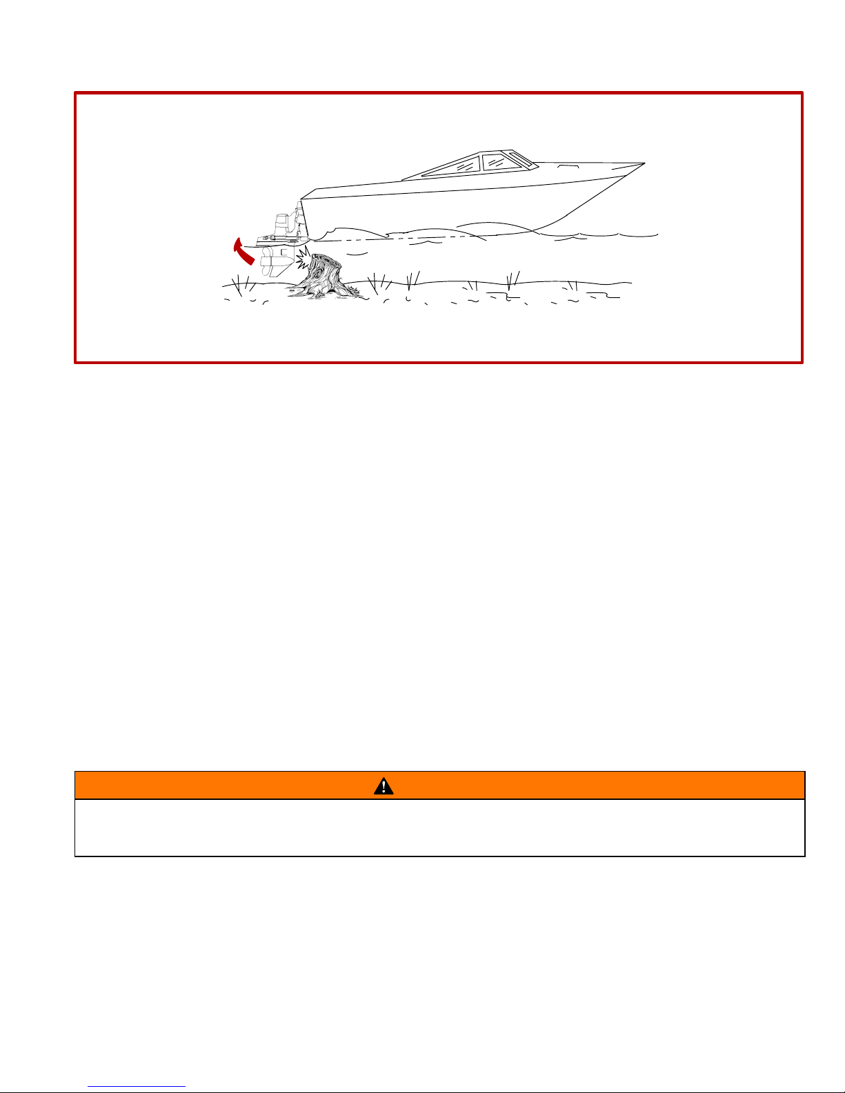
Drive Unit Impact Protection
The Power Trim hydraulic system is designed to provide impact protection for drive unit. If a submerged object
is struck while boat is moving forward, the hydraulic system will cushion kick-up of drive unit as it clears the object,
reducing damage to unit. After drive unit has cleared object, the hydraulic system allows drive unit to return to
original operating position, preventing loss of steering control and engine over speed.
Use extreme caution when operating in shallow water or where underwater objects are known to be present.
Use extreme care to prevent striking submerged objects while operating in REVERSE. No impact protection is
provided in REVERSE.
If drive unit should strike a submerged object, stop engine as soon as possible and inspect drive unit for damage.
If damage is present or suspected, boat should be taken to an Authorized MerCruiser Dealer for thorough inspection and necessary repair. Operating a damaged drive unit could cause additional damage to other parts of drive
unit, or could affect control of boat. If continued running is necessary, do so at greatly reduced speeds.
IMPORTANT: Impact protection system cannot be designed to ensure total protection from impact damage under all conditions.
27
Page 28

CA20
Launching and Boat Operation Care
CAUTION
During launching from a trailer, i f the unloading ramp is steep or the trailer bed must be tilted, the boat
may enter the water rapidly and at a steep angle. This may force water through the exhaust system into
the cylinders. The more weight on the transom, the more likely this is to occur.
Slowing down rapidly or stopping suddenly may cause a following wave to “swamp” the transom
causing water to enter the cylinders through the exhaust system causing severe engine damage.
When backing up rapidly, the same situation may occur as stated in the preceding paragraph.
In any of these situations, water entering the engine could cause severe damage to internal parts. Refer to
“Attention Required After Submersion”.
CA409
Attention Required After Submersion
• Before recovery, contact an Authorized MerCruiser Dealer.
• After recovery, immediate service by an Authorized MerCruiser Dealer is required to prevent serious damage
to power package.
CA19
Trailering Boat
Boat can be trailered with drive unit in up or down position. Adequate road clearance is required between road
and gear housing skew when trailering with drive unit in down position.
If adequate road clearance is a problem, place drive unit in full trailer position and support with an optional trailer
kit which is available from your Authorized MerCruiser Dealer.
CA21
Stolen Power Package
If your power package is stolen, immediately advise the local authorities and Mercury Marine of the model and
serial number(s) and to whom the recovery is to be reported. This “Stolen Motor” information is placed into a file
at Mercury Marine to aid authorities and dealers in recovery of stolen motors.
CE9
Replacement Service Parts
Marine engines are expected to operate at or near full throttle for most of their life. They are also expected to
operate in both fresh and saltwater environments. These conditions require numerous special parts. Care should
be exercised when replacing marine engine parts, as specifications are quite different from those of the standard
automotive engine.
Since marine engines must be capable of running at or near maximum RPM much of the time, special pistons,
camshafts and other heavy-duty moving parts are required for long life and peak performance.
These are but a few of the many special modifications that are required in MerCruiser marine engines to provide
long life and dependable performance.
28
Page 29

CA772
Do-It-Yourself Maintenance Suggestions
If you are one of those persons who likes to do-it-yourself, here are some suggestions for you.
• Present-day marine equipment, such as your MerCruiser power package, are highly technical pieces of
machinery. Electronic ignition and special fuel delivery systems provide greater fuel economies, but also are
more complex for the untrained mechanic.
• Do not attempt any repairs which are not covered in this manual unless you are aware of the precautions
(“Cautions” and “Warnings”) and procedures required. Your safety is of our concern.
• If you attempt to service the product yourself, we suggest you order the service manual for that model. The
service manual outlines the correct procedures to follow . It is written for the trained mechanic, so there may
be procedures you don’t understand. Do not attempt repairs if you do not understand the procedures.
• There are special tools and equipment that are required to perform some repairs. Do not attempt these repairs
unless you have these special tools and/or equipment. You can cause damage to the product in excess of
the cost a dealer would charge you.
• Also, if you partially disassemble an engine or drive assembly and are unable to repair it, the dealer ’s
mechanic must reassemble the components and test to determine the problem. This will cost you more than
taking it to the dealer immediately upon having a problem. It may be a very simple adjustment to correct the
problem.
• Do not telephone the dealer, service office or the factory to attempt for them to diagnose a problem or request
the repair procedure. It is difficult for them to diagnose a problem over the telephone.
• Your Authorized Dealer is there to service your power package. They have qualified factory-trained
mechanics.
It is recommended you have the dealer do periodic maintenance checks on your power package. Have them
winterize it in the fall and service it before the boating season. This will reduce the possibility of any problems
occurring during your boating season when you want trouble-free boating pleasure.
29
Page 30

CD329
Diagnosing EDI Problems (If So Equipped)
Your Authorized MerCruiser Dealer has the proper service tools for diagnosing problems on Electronic Diesel
Injection (EDI) Systems. The Electronic Control Module (ECM) on these engines have the ability to detect some
problems with the system when they occur, and store a “Trouble Code” in the ECM’s memory. This code can
then be read later by a service technician using a special diagnostic tool.
CE335
Multiple EDI Engine Battery Precautions
SITUATION
Alternators: Alternators are designed to charge the battery that supplies electrical power to the engine that the
alternator is mounted on. When batteries for two different engines are connected, one alternator will supply all
of the charging current for both batteries. Normally, the other engine’s alternator will not be required to supply
any charging current.
EDI Electronic Control Module (ECM): The ECM requires a stable voltage source. During multiple engine operation, an onboard electrical device may cause a sudden drain of voltage at the engine’s battery. The voltage
may go below the ECM’s minimum required voltage. Also, the alternator on the other engine may now start
charging. This could cause a voltage spike in the engine’s electrical system.
In either case, the ECM could shut off. When the voltage returns to the range that the ECM requires, the ECM
will reset itself. The engine will now run normally. This ECM shut down usually happens so fast that the engine
just appears to have an ignition miss.
Recommendations
Batteries: Boats with multi-engine EDI power packages require each engine be connected to its own battery.
This ensures that the engine’s Electronic Control Module (ECM) has a stable voltage source.
Battery Switches: Battery switches should always be positioned so each engine is running off its own battery.
DO NOT operate engines with switches in BOTH or ALL position. In an emergency, another engine’s battery can
be used to start an engine with a dead battery.
Battery Isolators: Isolators can be used to charge an auxiliary battery used for powering accessories in the
boat. Isolators should not be used to charge the battery of another engine in the boat unless the type of isolator
is specifically designed for this purpose.
Generators: The generator ’s battery should be considered in the same manner as another engine’s battery.
30
Page 31

CD625
Engine Break-In
INITIAL BREAK-IN PROCEDURE
It is especially important that the following procedure be used on new diesel engines. This break-in procedure
allows the proper seating of the pistons and rings, which greatly reduces the likelihood of problems.
IMPORTANT: It is recommended that the boat not be accelerated hard until this procedure has been
completed.
IMPORTANT: Never operate the starter motor longer than 15 seconds at a time, to avoid overheating the
starter motor. If engine does not start, wait 1 minute to allow the starter motor to cool; then, repeat starting procedure.
1. Follow instructions “a” or “b”:
a. On D2.8L D-Tronic and D4.2L D-Tronic Engines: Proceed to Step 2.
b. On D3.6L, D4.2L and D4.2L LD Engines Only: After a lengthy layup (several months or more) pre-lubricate the turbocharger and engine. To do this, hold the STOP switch toggle lever DOWN while you simultaneously turn the key switch to ST ART position for 15 seconds. This will rotate the starter motor and engine/oil
pump. During this process the engine will not run because no fuel is injected. Allow the starter motor to cool
down for one minute and repeat the above described process. To avoid overheating the starter motor, do
not engage starter motor for more than 15 seconds each time. Proceed to step 2 after a slight increase in
oil pressure is observed.
2. Refer to appropriate “Starting, Shifting and Stopping” section and start engine. Allow engine to idle until it
has reached normal operating temperature.
3. Run engine in gear for 3 minutes at each of the following rpms: 1200 rpm, 2400 rpm and 3000 rpm.
4. Run engine in gear for 3 minutes at each of the following rpms: 1500 rpm, 2800 rpm and 3400 rpm.
5. Run engine in gear for 3 minutes at each of the following rpms: 1800 rpm, 3000 rpm and Maximum Rated
Full Throttle rpm.
CE11
20-HOUR BREAK-IN PERIOD
IMPORTANT: The first 20 hours of operation is the engine break-in period. Correct break-in is essential
to obtain minimum oil consumption and maximum engine performance. During this break-in period, the
following rules must be observed:
• DO NOT operate engine below 1500 RPM for extended periods during the first 10 hours. During this period,
shift into gear as soon as possible after starting engine and advance throttle so that RPM is above 1500 (provided that conditions permit safe operation at this speed).
• DO NOT operate at any one constant speed for extended periods.
• DO NOT exceed 75% of full throttle during the first 10 hours except during engine Initial Break-In Procedure.
During the next 10 hours, occasional operation at full throttle (5 minutes at a time maximum) is permissible.
• AVOID full throttle acceleration from stopped position.
• DO NOT operate at full throttle until engine reaches normal operating temperature.
• OBSERVE INSTRUMENTS, if an abnormal reading occurs, stop engine immediately and determine cause.
• FREQUENTLY CHECK crankcase oil and sterndrive unit fluid levels. Add if necessary. It is normal for oil con-
sumption to be somewhat high during the break-in period.
• AT END OF 20-HOUR break-in period, remove break-in oil and replace oil filter. Fill crankcase with correct
grade and viscosity oil.
31
Page 32

CD608
Sterndrive Unit 10-Hour Break-In Period
It is especially important that the following procedure be used on new sterndrive units. This break-in procedure
allows the proper seating of drive unit gears and related components, which greatly reduces the likelihood of
problems.
1. Avoid full throttle starts.
2. DO NOT operate at any one constant speed for extended periods of time.
3. DO NOT exceed 75% of full throttle during the first 5 hours. During the next 5 hours, operate at intermittent
full throttle.
4. Drive unit should be shifted into forward gear a minimum of 10 times during break-in, with run-in time at
moderate rpm after each shift.
CA211
After Break-In Period
To help extend the life of your MerCruiser power package, the following recommendations should be considered;
• Use a propeller that allows the engine to operate at or near the top of the maximum RPM range (See
“Specifications” section) when at full throttle with a normal boat load.
• Operation at 3/4 throttle setting or lower is recommended. Refrain from prolonged operation at maximum (full
throttle) RPM.
CA414
End of First Season Checkup
At the end of the first season of operation, an Authorized MerCruiser Dealer should be contacted to discuss
and/or perform various scheduled maintenance items. If you are in an area where the product is operated
continuously (year-round operation), you should contact your dealer at the end of the first 100 hours of operation,
or once yearly, whichever occurs first.
CE299
100 Hour Checkup
It is a condition for the continuation of warranty, that the product be taken to an authorized MerCruiser service
dealer after the first 100 hours of operation, but no later than 150 hours, for cylinder head retorque service. A
copy of the dealer service work order must be kept, by the product owner , as evidence of compliance therewith.
32
Page 33

THIS PAGE IS INTENTIONALLY BLANK
33
Page 34

CD334
1
4
71856
72753
2
71856
3
5
71856
71856
6
7
34
71856
71772
73546
718868B
9
8A
73547
Page 35

CD9
Operation
CD626
Quicksilver Instruments and Instrumentation
Shown is the basic Quicksilver instrumentation and engine system monitor display for the Diesel Power Package. The instrumentation shown is required for safe operation of boat and engine. Operator should become familiar with all instrumentation before operating the engines.
Gauges and engine system monitor panel may be individually mounted, or collectively mounted in the optional
single panel available from Quicksilver.
NOTE: Refer to manufacturer’s instructions and explanations about instrumentation, if equipped with other than
Quicksilver instrumentation.
1 Oil Pressure Gauge - indicates engine oil pressure. Refer to “Specifications” for normal operating readings.
2 Tachometer - indicates engine speed (rpm).
3 Coolant Temperature Gauge - indicates engine coolant temperature. Refer to “Specifications” for normal
operating readings.
4 Cruise Log (Engine Hour Meter) - records engine running time.
5 Voltmeter- indicates battery voltage, and if alternator and charging circuit are functioning properly . The green
area on the gauge is the normal operating range.
6 Trim/Tilt Gauge - indicates drive unit trim angle (UP/OUT or DOWN/IN).
7 Audio Warning Buzzer Standard Features - Buzzer sounds if:
(1) Cooling system temperature too high
(2) Oil pressure too low
(3) Drive unit oil too low
8 Key Switch - has three positions. In the OFF position, all electrical circuits are off and engine cannot be
started. In the RUN position, all electrical circuits, indicator lamps, automatic preheating (if equipped) and all
instruments are operational. In the START position the engine can be started.
NOTE: Key can only be removed in the OFF position.
A D3.6L, D4.2L and D4.2L LD - If engine is running the key switch cannot be used to stop engine. The engine
can only be stopped by using the Engine Stop Switch, while the Key Switch is in the RUN position
cal circuit is operational when the key switch is turned to the OFF position.
. No electri-
B D2.8L D-Tronic and D4.2L D-Tronic - The engine is stopped when the key switch is turned to the OFF posi-
tion.
9 Engine Stop Switch - D3.6L, D4.2L and D4.2L LD - is used to stop the engine. This is done by electrically
shutting off fuel delivery system. Stop Switch is toggled DOWN and held until engine stops completely. Then,
key switch can be turned to the OFF position.
35
Page 36

CD491
n
1
2
CD492
BCDAE
71891
71891
3
71722
1 Engine System Monitor Features - The appropriate light functions as follows:
A Preheat Indicator Lamp - lights up when the glow plugs, if equipped, are preheating the combustion cham-
bers. The light stays on until the preheat period is complete. The timed preheat period begins when the key
switch is turned on, and then, only when the engine is cold. On D3.6L and D4.2L models, the engine can be
started only after the light goes out.
B Charge Indicator Lamp - indicates a problem with charging system if lamp illuminates while engine is running.
Lamp will light when key switch is ON and engine is not running. When engine starts, light should go off.
C Oil Pressure Warning Lamp - indicates low engine oil pressure if lamp illuminates while engine is running.
D Coolant Temperature Warning Lamp - indicates excessive engine coolant temperature if lamp illuminates
while engine is running.
NOTE: The oil pressure warning lamp is wired in a parallel circuit with the gear lube monitor bottle switch. If lamp
illuminates while engine is running and oil pressure and oil level are normal, this may be an indication of low oil
level in the gear lube monitor bottle. The cause should be determined and corrected.
E Malfunction Indicator Lamp (MIL), D2.8L D-Tronic and D4.2L D-Tronic Only - additional lamp indicates when
a problem exists, or a malfunction has occurred, that requires service.
2 Panel Lights / Audio Test Switch - has three positions; in the normal position all electrical circuits operate
in a standard fashion (as described above). With switch toggled UP the instrumentation lights are all illuminated.
When the switch is toggled DOWN the audio warning horn will sound allowing the operator to perform a test of
the audio warning horn.
3 20 Amp Fuse and Holder - located in-line on key switch power supply wire and protects the Instrumentation
and wiring should an electrical overload occur. If an overload occurs, the fuse will burn out. Check “blown”
(burned) fuse if key is turned to RUN or START and nothing happens.
IMPORTANT: Cause for overload must be determined and corrected before attempting to install new
fuse or fuse failure will occur again.
After cause is corrected, install new fuse and check systems to function.
36
Page 37

CD636
1
74703
3
71630
2
73546
CD495
4
22444
Electrical System Overload Protection
lf an electrical overload occurs, a fuse will blow or a circuit breaker will trip open.
IMPORTANT: The cause must be found and corrected before replacing fuse or resetting circuit breaker .
1 Two 60 amp circuit breakers provide protection for engine wiring harness and instrumentation power lead.
Reset by pushing RESET button IN (on outside).
In an emergency, when engine must be operated and cause for high current draw cannot be located and cor-
rected, turn OFF or disconnect all accessories connected to engine and instrumentation wiring. Reset circuit
breaker. If breaker remains open, electrical overload has not been eliminated. Further checks must be made on
electrical system.
2 When equipped with Quicksilver instrumentation and wiring a 20 amp fuse and holder is located in-line on
key switch power supply wire and protects the Instrumentation and wiring should an electrical overload occur.
If an overload occurs, the fuse will burn out. Check “blown” (burned) fuse if key is turned to RUN or START and
instruments do not work and/or if switches do not function.
3 The Power Trim system is protected from overload by 110 amp fuse and a 20 amp in-line fuse on Power Trim
pump.
CA31
MerCathode System
4 A 20 amp in-line fuse is in the wire which connects to positive (+) terminal on controller. If fuse is “blown” (de-
fective), the system will not operate.
37
Page 38

CD197
1
7
3
2
11
9
10
8
5
6
4
12
8
11
12
10
38
9
13
Page 39

CD195
Remote Controls (Panel Mounted)
Your boat may be equipped with one of many Quicksilver remote controls available. All controls feature an
integral safety switch that allows starting engine in NEUTRAL only. Also, all controls may not have all features
shown.
NOTE: If boat is equipped with a remote control other than shown, consult your dealer for a description and/or
demonstration of the control.
1 Neutral Lock Bar - Prevents accidental shift and throttle engagement. Neutral lock bar must be pulled “Up”
to move the control handle out of neutral.
2 Throttle Only Button - Allows engine throttle advancement without shifting the engine. This is done by disen-
gaging the shift mechanism from the control handle. The throttle only button can be depressed only when the
remote control handle is in the “Neutral” position, and should only be used to assist in starting the engine.
3 Power Trim Switch - See “Power Trim” for detailed power trim operating procedures.
4 Trailer Switch - Used to raise drive unit for trailering, launching, breaching or shallow water operation. See
“Power Trim” for detailed trailer switch operation.
5 Lanyard Stop Switch - Turns ignition “Off” whenever the operator (when attached to the lanyard) moves far
enough away from the operator’s position to activate the switch. See “Lanyard Stop Switch” at the front of this
manual for safety warning on the use of this switch.
6 Control Handle Tension Adjustment Screw - This screw can be adjusted to “Increase” or “Decrease” the
tension on the control handle. This will help prevent “Creep” of the remote control handle. T urn screw “Clockwise”
to increase tension and “Counterclockwise” to decrease tension. Adjust to tension desired.
7 Control Handle - Operation of the shift and throttle are controlled by the movement of the control handle.
“Push” the control handle forward from “Neutral” with a quick firm motion to the first detent for “Forward” gear.
Continue pushing forward to increase speed. Pull the control handle back from “Neutral” with a quick firm motion
to the first detent for “Reverse” gear. Continue pushing back to increase speed.
CD196
Remote Controls (Console Mounted)
Your boat may be equipped with one of many Quicksilver remote controls available. All controls feature an
integral safety switch that allows starting engine in NEUTRAL only. Also, all controls may not have all features
shown.
NOTE: If boat is equipped with a remote control other than shown, consult your dealer for a description and/or
demonstration of the control.
8 Control Handle(s) - Operation of the the shift and throttle are controlled by the movement of the control han-
dle. “Push” the control handle forward from “Neutral” with a quick firm motion to the first detent for “Forward” gear.
Continue pushing forward to increase speed. Pull the control handle back from “Neutral” with a quick firm motion
to the first detent for “Reverse” gear. Continue pushing back to increase speed.
9 Throttle Only Button - Allows engine throttle advancement without shifting the engine. This is done by disen-
gaging the shift mechanism from the control handle. The throttle only button can be depressed only when the
remote control handle is in the “Neutral” position, and should only be used to assist in starting the engine.
10Control Handle Tension Adjustment Screw - This screw can be adjusted to “Increase” or “Decrease” the
tension on the control handle (cover must be removed to adjust). This will help prevent “Creep” of the remote
control handle. Turn screw “Clockwise” to increase tension and “Counterclockwise” to decrease tension. Adjust
to tension desired.
11 Power Trim Switch - See “Power Trim” section for detailed power trim operating procedures.
12Trailer Switch - Used to raise drive unit for trailering, launching, breaching or shallow water operation. See
“Power Trim” for detailed trailer switch operation.
13Power Trim Adjustment Switches (Used on Three Button Trim Control Only) - See “Power Trim” section
for detailed power trim operating procedures.
39
Page 40

CD552
1
71339
2
4
40
3
70537
Page 41
CD217
Remote Controls (Two Lever)
Your boat may be equipped with one of many Quicksilver remote controls available. All controls feature an
integral safety switch that allows starting engine in NEUTRAL only. Also, all controls may not have all features
shown.
NOTE: If boat is equipped with a remote control other than shown, consult your dealer for a description and/or
demonstration of the control.
1 Shift Lever - shifts unit into gear with full lever movement. Move lever forward to shift to FORWARD gear.
Move lever backward to shift to REVERSE gear. Lever in full vertical position shifts to NEUTRAL.
CAUTION
Never shift unit into or out of gear unless throttle lever is a idle rpm.
2 Throttle Lever - allows engine rpm to be increased or decreased.
3 FRICTION Screw - adjusts control handle friction so motor speed can be set and driver does not have to hold
handle.
Turn screw clockwise to increase friction. Do not thread screw all the way out.
4 DETENT Screw - controls the effort needed to move control handle out of NEUTRAL. To increase tension,
turn screw clockwise; to decrease, turn screw counterclockwise. Do not thread screw all the way out.
IMPORTANT: Boats equipped with dual power packages may have both shift levers on one control and
both throttle levers on the other control.
41
Page 42

CD553
°
3 - 5
1
2
3
42
Page 43

CA35
Power Trim
The Power Trim system allows operator to raise and lower drive unit for trailering, beaching, launching and
shallow water operation. Power Trim also allows operator to adjust drive unit angle, while underway, to provide
ideal boat angle for varying load and water conditions.
1 In most cases, best overall performance is obtained with drive unit adjusted so boat will run at a 3° to 5° angle
to water.
CA36
2 Trimming Drive Unit UP/OUT Will:
• Lift bow of boat.
• Generally increase top speed.
• Increase clearance over submerged objects.
• Cause boat to accelerate and plane off slower.
• In excess, cause porpoising and/or propeller ventilation.
• Cause overheating if trimmed up/out beyond gimbal ring support flanges.
CAUTION
Never trim drive unit up/out using TRAILER switch while boat is underway. Severe damage to drive unit
may result if unit is raised beyond gimbal ring support flanges at engine speeds above 1200 rpm. For
shallow water operation, use extreme caution when operating boat with drive unit raised.
CD554
3 Trimming Drive Unit DOWN/IN Will:
• Help boat accelerate and plane off quicker.
• Generally improve ride in choppy water.
• In most cases, reduce boat speed.
• If in excess, lower the bow of some boats to a point at which they begin to plow with their bow in the water
while on plane. This can result in an unexpected turn in either direction called “bow steering” or “over steering”
if any turn is attempted, or if a significant wave is encountered.
43
Page 44

CD199
2
3
1
73976
5
6
4
44
73977
Page 45

CB188
POWER TRIM OPERATION - PANEL MOUNT REMOTE CONTROL
IMPORTANT: If TRAILER button is held depressed after drive unit reaches end of upward travel, an internal circuit breaker will open and pump will stop. Should this happen, release button and allow motor to
cool for about one minute. Circuit breaker will reset and Power Trim operation may be resumed.
1 Trailer Position: Press button until drive unit reaches desired height.
2 Trim UP/OUT: Press UP on Trim switch until drive unit reaches desired trim position.
3 Lower Drive Unit: Press DOWN on Trim switch until drive unit reaches desired position.
CB189
POWER TRIM OPERATION - CONSOLE MOUNT REMOTE CONTROL
(SINGLE ENGINE VERSION)
4 Trailer Position: Press button until drive unit reaches desired height.
5 Trim UP/OUT: Press UP on Trim switch until drive unit reaches desired trim position.
6 Lower Drive Unit: Press DOWN on Trim switch until drive unit reaches desired position.
45
Page 46

CD200
2A
1
2B
73979
4
1
73978
3
5
70540
46
6
7
70540
70540
Page 47

CA627
POWER TRIM OPERATION - DUAL ENGINE CONSOLE MOUNT REMOTE CONTROL (TWO BUTTON
AND THREE BUTTON VERSIONS)
IMPORTANT: If TRAILER button is held depressed after drive unit reaches end of upward travel, an internal circuit breaker will open and pump will stop. Should this happen, release button and allow motor to
cool for about one minute. Circuit breaker will reset and Power Trim operation may be resumed.
CAUTION
When lowering or raising sterndrives equipped with a dual engine tie bar kit, the sterndrives must be
raised or lowered evenly to prevent the tie bar from becoming twisted. Failure to raise or lower
sterndrives evenly may result in tie bar or sterndrive damage.
1 Trailer Button (Both Versions) - Press button until drive unit reaches desired height for trailering drive units.
2 Two Button Trim Control (Dual Buttons in Handle) - used to control both drive units from the handle. Press
UP on button(s) to trim drive unit UP/OUT. Press down on button(s) to trim drive unit DOWN/IN.
A Forward Trim Button - Used to trim the port drive unit.
B Rear Trim Button - Used to trim the starboard drive unit.
3 Three Button Trim Control (Trim Adjustment Switches) - With a single integral trim button in the handle
to control two drive units simultaneously, these two switches control the fine tune adjustment of each drive unit.
Using these Fine Tune Switches, set each drive unit to the desired trim angle. Then use the single trim switch
in the handle to control the trim of both drive units simultaneously.
4 Three Button Trim Control (Single Trim Switch in Handle) - used to trim both drives simultaneously after
drives have been fine-tuned as described above.
CB193
POWER TRIM OPERATION - THREE BUTTON TRIM PANEL
(USED ON MODELS WITH TWO-LEVER CONTROL)
IMPORTANT: If TRAILER button is held depressed after drive unit reaches end of upward travel, an internal circuit breaker will open and pump will stop. Should this happen, release button(s) and allow motor
to cool for about one minute. Circuit breaker will reset and Power Trim operation may be resumed.
5 Trailer Position: Simultaneously press the UP button (top) along with the UP/OUT button (center) until drive
unit reaches desired trailer position.
6 Trim Drive Unit UP/OUT: Press center UP/OUT button until drive unit reaches desired trim position.
7 Trim Drive Unit IN/DOWN: Press IN button until drive unit reaches desired trim position.
47
Page 48

CD599
2B
2A
1A
71386
1B
76378
3
48
Page 49

CD628
Starting, Shifting and Stopping - D3.6L, D4.2L and D4.2L LD
NOTE: Does not include engines equipped with D-Tronic fuel injection.
WARNING
Do not use volatile starting aids, such as Ether, Propane, or Gasoline in the engine air intake system.
Explosion hazard resulting from ignition of vapors by glow plugs could cause severe personal injury
and engine damage.
CAUTION
It is good practice to ventilate the engine compartment prior to servicing any engine components to
remove any fuel vapors which may cause difficulty breathing or be an irritant.
1 Cold Start Assist:
A On D3.6L and D4.2L models, a Cold Start Lever located on the injection pump is used to aid in starting when
the temperature is below 50°F (10° C). This is done by moving lever in direction shown. Lever should be reset
as soon as engine starts and idles smoothly.
B On D4.2L LD models, a Cold Start Device located on the injection pump is used to aid in starting when the
temperature is below 50°F (10° C). This is done using an electric solenoid and a coolant temperature switch
circuit. Lever will reset as soon as engine coolant reaches a prescribed temperature.
2 Mechanical Engine Stop Lever - located on the injection pump of all engines except D-Tronic Engines. It is
used to manually shut of f engine by cutting of f the fuel supply. It can be engaged by moving the lever in the direction shown.
A On D3.6L and D4.2L Models.
B On D4.2L LD Models.
BEFORE STARTING THE ENGINE
IMPORTANT: As an added precaution, the following steps must be observed before starting:
• Do not start engine without water being supplied to seawater pickup pump (to prevent pump or en-
gine damage).
• Never operate the starter motor longer than 15 seconds at a time, to avoid overheating the starter mo-
tor. If engine does not start, wait 1 minute to allow the starter motor to cool; then, repeat starting procedure.
• Be sure engine crankcase is filled to correct level with the proper grade of oil for the prevailing tem-
perature. Refer to “Specifications - Crankcase Oil.”
• Be sure that all electrical connections are secure.
• Check the air cleaner for proper installation of filter element.
3 Check all items listed in the Maintenance Schedules and Operation Chart - D3.6L, D4.2L and D4.2L LD. Refer
to “Table Of Contents.”
4 Perform any other necessary checks, as indicated by your dealer, or specified in your boat owner’s manual.
49
Page 50

CD629
STARTING COLD ENGINE
IMPORTANT: Always check all fluid levels before starting engine. Refer to Maintenance Chart.
1 Turn on and run engine compartment bilge blower (if equipped) for five minutes. Or, open engine hatch to
air out bilge before attempting to start engine(s).
2 On D3.6L and D4.2L only, set “Cold Start Lever” if temperature is below 50° F (10° C).
3 After a lengthy layup (several months or more) pre-lubricate the turbocharger and engine. To do this, hold
the STOP switch toggle lever DOWN while you simultaneously turn the key switch to START position for 15 seconds. This will rotate the starter motor and engine/oil pump. During this process the engine will not run because
no fuel is injected. Allow the starter motor to cool down for one minute and repeat the above described process.
To avoid overheating the starter motor, do not engage starter motor for more than 15 seconds each time. Proceed
to next step after a slight increase in oil pressure is observed.
4 If engine has not been run for a period of time and will not readily start with the standard starting procedure,
there is a hand pump/primer knob located on the fuel filter header . Move knob up and down four or five strokes.
5 Turn key switch to the RUN position. Observe indicator lamp for glow plugs. When cylinder temperature is
great enough to sustain combustion, the indicator lamp will cease to be lighted and the engine can be started.
6 Turn key switch to START position and release when engine fires. Check to ensure charge indicator and oil
pressure warning lamps go out.
CAUTION
Improper or no warm-up of engine can seriously impair the Iife of your diesel engine.
NOTE: On D3.6L and D4.2L only, reset Cold Start Lever when engine idles smoothly.
7 Run engine at Idle rpm until engine temperature is within normal operating range.
CAUTION
Never attempt to shift unit unless engine is at idle rpm. Damage to drive unit could occur.
8 Check to ensure all instrumentation is functioning properly and indicating normal readings.
CE31
ENGINE WARM UP
CAUTION
Improper or no warm-up of engine can seriously impair the Iife of your diesel engine.
9 After starting, check to ensure all instrumentation is functioning properly. Run engine at idle RPM until engine
temperature is within normal operating range. It is very important that any engine be warmed up before applying
full load. The warm-up period provides time for the lubricating oil to establish a film between moving parts.
NOTE: Engine warm-up time during cold weather can be reduced by operating vessel at reduced engine speed.
Commence normal vessel operation when systems reach operating temperatures.
10After the engine has reached operating temperature, oil pressure should be within range listed in the engine
specifications chart. Stop the engine if oil pressure is not within this range. Locate and correct the problem, or
see your Authorized MerCruiser Dealer if you are unable to determine the problem.
50
Page 51
CD340
STARTING WARM ENGINE
1 Turn on and run engine compartment bilge blower for five minutes (if so equipped). Or, open engine hatch
to air out bilge before attempting to start engine(s).
2 Turn key switch to the RUN position.
3 Turn key switch to START position and release when engine fires. Check to ensure charge indicator and oil
pressure warning lamps go out.
CAUTION
Improper or no warm-up of engine can seriously impair the Iife of your diesel engine.
4 Check to ensure all instrumentation is functioning properly and indicating normal readings.
CE33
SHIFTING
CAUTION
Never attempt to shift unit unless engine is at idle RPM. Damage to drive unit could occur.
1 To shift unit, be sure remote control/throttle lever is in NEUTRAL. Move control/shift lever with a firm, quick
motion forward to shift to FORWARD gear, or backward to shift to REVERSE. After shifting drive unit, advance
throttle to desired setting.
2 Once underway, engine oil pressure should be within the range listed in the engine specifications chart at
maximum RPM, or Wide-Open-Throttle. Stop the engine if oil pressure is not within this range. Locate and correct the problem, or see your Authorized MerCruiser Dealer if you are unable to determine the problem.
CB575
IMPORTANT: Avoid stopping engine if the drive unit is in gear. If engine does stop with drive unit in gear,
refer to the following procedure:
3 Push and pull repeatedly on remote control handle until handle returns to the neutral detent position. This may
take several tries if the power package was operating above idle RPM when the engine stopped.
4 After handle returns to the neutral detent position, resume normal starting procedures.
CD341
ENGINE SHUT-DOWN (STOPPING)
5 Place remote control lever in NEUTRAL.
CAUTION
Avoid damaging the turbocharger and engine. Immediate engine shutdown (stopping) after high load
operation may result in permanent turbocharger bearing damage. Operate the engine at IDLE for several minutes before shut-down.
6 Operate the engine at idle speed for several minutes to allow the turbocharger and engine to cool.
7 Toggle STOP switch DOWN and hold, until engine stops completely.
8 Turn key switch to the OFF position.
51
Page 52

CD630
Operation Chart - D3.6L, D4.2L and D4.2L LD
STARTING
PROCEDURE
Open engine hatch. Air
out bilge completely.
Turn battery switch ON,
if so equipped.
Turn on and run engine
compartment bilge blower, if so equipped, for five
minutes.
Check for leaks - fuel, oil,
water, fluid, etc.
Open fuel shut-off valve,
if so equipped.
Open seacock, if so
equipped.
Check that mechanical
engine-stop lever is not
engaged.
Prime fuel injection system, if necessary.
AFTER
STARTING
Observe all gauges and
warning lights to check
condition of engine. If not
normal, stop engine.
Check for fuel, oil, water,
fluid, and exhaust leaks,
etc.
Check shift and throttle
control operation.
Check steering operation.
WHILE
UNDERWAY
Frequently observe all
gauges and indicator
lights to monitor engine
condition.
STOPPING &
SHUT DOWN
Shift remote control lever
to neutral position.
Run engine at idle speed
several minutes to allow
the turbocharger and
engine to cool.
Toggle STOP switch
“Down” and hold, until
engine completely
stops.
Turn key switch to OFF
position.
Turn battery switch OFF,
if so equipped.
Close fuel shut-off valve,
if so equipped.
Close seacock, if so
equipped.
Flush seawater cooling
circuit, if operating in
saltwater area.
Pre-lubricate turbocharger and engine, if necessary.
Turn key switch to “RUN”
and check that lights and
indicator lamps come
on.
Turn key switch to
START, after the indicator lamp for glow
plugs (if so equipped)
ceases. Release key
when engine starts.
Check that charge indicator and oil pressure indicator lamps cease AFTER
engine starts.
Warm-up engine at idle
RPM for several minutes.
52
Page 53

CD631
75301
CE297
1
Starting, Shifting and Stopping - D2.8L D-Tronic and D4.2L D-Tronic
WARNING
Do not use volatile starting aids, such as Ether, Propane, or Gasoline in the engine air intake system.
Explosion hazard resulting from ignition of vapors by glow plugs could cause severe personal injury
and engine damage.
CAUTION
It is good practice to ventilate the engine compartment prior to servicing any engine components to
remove any fuel vapors which may cause difficulty breathing or be an irritant.
BEFORE STARTING THE ENGINE
IMPORTANT: As an added precaution, the following steps must be observed before starting:
• Do not start engine without water being supplied to seawater pickup pump (to prevent pump or en-
gine damage).
• Never operate the starter motor longer than 15 seconds at a time, to avoid overheating the starter mo-
tor. If engine does not start, wait 1 minute to allow the starter motor to cool; then, repeat starting procedure.
• Be sure engine crankcase is filled to correct level with the proper grade of oil for the prevailing tem-
perature. Refer to “Specifications - Crankcase Oil.”
• Be sure that all electrical connections are secure.
• Check the air cleaner for proper installation of filter element.
1 Check all items listed in the Maintenance Schedules and Operation Chart - D2.8L D-Tronic and D4.2L D-Tron-
ic (refer to “Table Of Contents”).
2 Perform any other necessary checks, as indicated by your dealer, or specified in your boat owner’s manual.
53
Page 54

CE298
STARTING COLD ENGINE
IMPORTANT: Always check all fluid levels before starting engine. Refer to Maintenance Chart.
1 Turn on and run engine compartment bilge blower (if so equipped) for five minutes. Or, open engine hatch
to air out bilge before attempting to start engine(s).
2 If engine has not been run for a period of time and will not readily start with the standard starting procedure,
there is a hand pump/primer knob located on the fuel filter header . Move knob up and down four or five strokes.
Attempt to start engine following normal procedure.
3 Turn key switch to the RUN position. Observe indicator lamp for glow plugs, if so equipped. When cylinder
temperature is great enough to sustain combustion, the indicator lamp will cease to be lighted and the engine
can be started.
4 Turn key switch to START position. Release key when engine starts and allow switch to return to RUN posi-
tion.
5 Check to ensure all instrumentation is functioning properly and indicating normal readings. Check to ensure
charge indicator and oil pressure warning lamps go out. Within seconds after starting the engine, oil pressure
should exceed 10 psi (69 kPa) minimum. If the oil pressure does not meet these minimum limits, stop the engine,
locate and correct the problem, or see your Authorized MerCruiser Dealer if you are unable to determine the
problem.
CAUTION
Do not increase the engine speed until the oil pressure gauge indicates normal. Shut the engine down
if oil pressure does not register on the gauge within 20 to 30 seconds after start.
CE31
ENGINE WARM UP
CAUTION
Improper or no warm-up of engine can seriously impair the Iife of your diesel engine.
1 After starting, check to ensure all instrumentation is functioning properly. Run engine at idle RPM until engine
temperature is within normal operating range. It is very important that any engine be warmed up before applying
full load. The warm-up period provides time for the lubricating oil to establish a film between moving parts.
NOTE: Engine warm-up time during cold weather can be reduced by operating vessel at reduced engine speed.
Commence normal vessel operation when systems reach operating temperatures.
2 After the engine has reached operating temperature, oil pressure should be within range listed in the engine
specifications chart. Stop the engine if oil pressure is not within this range. Locate and correct the problem, or
see your Authorized MerCruiser Dealer if you are unable to determine the problem.
54
Page 55
CE32
STARTING WARM ENGINE
1 Turn on and run engine compartment bilge blower for five minutes (if so equipped). Or, open engine hatch
to air out bilge before attempting to start engine(s).
2 Turn key switch to the RUN position. Check to ensure glow plug preheat lamp is not illuminated.
3 Turn key switch to the START position and release when engine fires. Check to ensure charge indicator and
oil pressure warning lamps go out.
4 Check to ensure all instrumentation is functioning properly and indicating normal readings. Oil pressure
should be within the range listed in the engine specifications chart. Stop the engine if oil pressure is not within
this range. Locate and correct the problem, or see your Authorized MerCruiser Dealer if you are unable to determine the problem.
CE33
SHIFTING
CAUTION
Never attempt to shift unit unless engine is at idle RPM. Damage to drive unit could occur.
5 To shift unit, be sure remote control/throttle lever is in NEUTRAL. Move control/shift lever with a firm, quick
motion forward to shift to FORWARD gear, or backward to shift to REVERSE. After shifting drive unit, advance
throttle to desired setting.
6 Once underway, engine oil pressure should be within the range listed in the engine specifications chart at
maximum RPM, or Wide-Open-Throttle. Stop the engine if oil pressure is not within this range. Locate and correct the problem, or see your Authorized MerCruiser Dealer if you are unable to determine the problem.
CB575
IMPORTANT: Avoid stopping engine if the drive unit is in gear. If engine does stop with drive unit in gear,
refer to the following procedure:
7 Push and pull repeatedly on remote control handle until handle returns to the neutral detent position. This may
take several tries if the power package was operating above idle RPM when the engine stopped.
8 After handle returns to the neutral detent position,resume normal starting procedures.
CD366
ENGINE SHUT-DOWN (STOPPING)
9 Place remote control lever in NEUTRAL.
CAUTION
Avoid damaging the turbocharger and engine. Immediate engine shutdown (stopping) after high load
operation may resulting in permanent turbocharger bearing damage. Operate the engine at IDLE for
several minutes before shut-down.
10Operate the engine at idle speed for several minutes to allow the turbocharger and engine to cool.
11 Turn key switch to the OFF position.
55
Page 56

CD346
Operation Chart - D2.8L D-T ronic and D4.2L D-Tronic
STARTING
PROCEDURE
Open engine hatch. Air
out bilge completely.
Turn battery switch ON,
if so equipped.
Turn on and run engine
compartment bilge blower, if so equipped, for five
minutes.
Check for leaks - fuel,
oil, water, fluid, etc.
Open fuel shutoff valve,
if so equipped.
Open seacock, if so
equipped.
AFTER
STARTING
Observe all gauges and
warning lights to check
condition of engine. If
not normal, stop engine.
Check for fuel, oil, water,
fluid, and exhaust leaks,
etc.
Check shift and throttle
control operation.
Check steering operation.
WHILE
UNDERWAY
Frequently observe all
gauges and indicator
lights to monitor engine
condition.
STOPPING &
SHUT DOWN
Shift remote control lever to neutral position.
Run engine at idle speed
several minutes to allow
the turbocharger and engine to cool.
Turn key switch to OFF
position.
Turn battery switch, if so
equipped, to OFF.
Close fuel shutoff valve,
if so equipped.
Close seacock, if so
equipped.
Prime fuel injection system, if necessary.
Turn key switch to RUN
and check that lights and
indicator lamps come
on.
Turn key switch to ST ART,
after the indicator lamp for
glow plugs (if so equipped)
ceases. Release key
when engine starts.
Check that charge indicator and oil pressure indicator lamps cease AFTER engine starts.
Warm-up engine at idle
RPM for several minutes.
Flush seawater cooling
circuit, if operating in saltwater area.
56
Page 57

CD7
Specifications
CD11
Seacock
Seacock (water inlet valve) used, must have an internal cross-sectional area equal to or greater than hose to
prevent restricting water flow. A 1-1/2 in. (38mm) brass ball or gate valve is minimum required.
Seacock should be installed in an area where it is easily accessible and supported adequately to prevent hose
fatigue.
CE14
Seawater Strainer
Seawater Strainer should be provided, and be of sufficient size to ensure that an adequate supply of water will
be maintained for cooling engine. A minimum flow rate of 40 gallons (150 litres) per minute is required.
Strainer should be installed in an area where it will be easily accessible for inspection and cleaning. Strainer
should be installed in water inlet hose after seacock to allow operator to shut off water inlet when cleaning strainer.
CD535
Anti-Freeze/Coolant
CAUTION
Alcohol or Methanol base antifreeze or plain water are not recommended for use in closed cooling
section of cooling system at any time.
Because diesel engines are high compression engines and related higher engine operating temperatures are
created, the closed cooling system and engine, including related cooling passages must remain as clean as possible to provide adequate engine cooling. This can only be assured by using the proper anti-freeze, water, additives
and inhibitors. It is recommended that the closed cooled section of the cooling system be filled with a low, or no,
silicate formula of ethylene glycol antifreeze in solution with deionized water. A low silicate formula prevents antifreeze separation which causes a silicate gelatin to form. This gelatin will block engine and heat exchanger passages causing engine overheating.
The coolant, if not premixed, should be mixed before being added to the closed cooling system using a proper
anti-freeze together with deionized water. Common tap water or softened water contains unwanted minerals
which can leave large deposits in the system that restrict the cooling system efficiency. I n addition, additives and
inhibitors introduced into acceptable coolant solutions will form a protective film on internal passages and provide protection against internal cooling system erosion.
The closed cooling section should be kept filled year-round with an acceptable anti/freeze/coolant solution. Do
not drain closed cooled section for storage, as this will promote rusting of internal surfaces. If engine will be exposed to freezing temperatures, make sure that closed cooled section is filled with a properly mixed antifreeze/
coolant solution, to protect engine and closed cooling system to lowest temperature to which they will be exposed.
IMPORTANT: The anti-freeze/coolant used in these marine engines must be a low (or no) silicate ethylene
glycol, containing special additives, and deionized, purified water. Using other types of engine coolant
may cause fouling of the heat exchangers, and overheating of the engine. Do not combine different types
of coolants without knowing that they are compatible. Refer to the coolant manufacturer’s instructions.
Some acceptable types of anti-freeze/coolants are listed in the following table. Refer to “Maintenance Schedules”
for respective change intervals.
Quicksilver Premixed Marine Engine Coolant 92-813054A2
Fleetguard Complete Obtain Locally
DESCRIPTION
PART NUMBER
57
Page 58
CD164
Fuel Requirements
WARNING
Electrical system components on this engine are not external ignition protected. DO NOT STORE OR
UTILIZE GASOLINE ON BOATS EQUIPPED WITH THESE ENGINES, UNLESS PROVISIONS HAVE BEEN
MADE TO EXCLUDE GASOLINE VAPORS FROM ENGINE COMPARTMENT (REF: 33 CFR). Failure to
comply could result in fire, explosion and/or severe personal injury.
WARNING
FIRE HAZARD: Fuel leakage from any part of the fuel system can be a fire hazard which can cause
serious bodily injury or death. Careful periodic inspection of entire fuel system is mandatory,
particularly after storage. All fuel components including fuel tanks, whether plastic, metal or
fiberglass, fuel lines, primers, fittings, and fuel filters should be inspected for leakage, soften,
hardening, swelling or corrosion. Any sign of leakage or deterioration requires replacement before
further engine operation.
IMPORTANT: Use of improper or water contaminated diesel fuel can damage your engine seriously . U s e
of improper fuel is considered misuse of engine, and damage caused thereby will not be covered by warranty.
WARNING
Under no circumstances should gasoline, gasohol and/or alcohol be mixed with diesel fuel for any
reason. This mixture of gasoline, gasohol and/or alcohol with diesel fuel is highly flammable and
produces a significant risk to the user.
Grade 2-D diesel fuel is required, meeting ASTM Standards D975 (or fuel rated Diesel DIN 51601), and having
a minimum cetane rating of 45.
The Cetane number is a measure of the ignition quality of diesel fuel. Increasing the cetane number will not improve overall engine performance, but it may be necessary to raise the cetane rating for low temperature, or high
altitude use. A lower cetane number could cause hard starting and slower warm-up, and could increase engine
noise and exhaust emissions.
NOTE: If your engine suddenly becomes noisy after a fuel fill, you possibly received substandard fuel with a
low cetane rating.
Sulphur content of the above fuel is rated at 0.50% by weight, maximum (ASTM). Limits may vary in countries
outside of the United States.
On intermittent use engines, high sulphur content diesel fuel will greatly increase:
• Corrosion on metal parts.
• Deterioration of elastomer and plastic parts.
• Corrosion and extensive damage, and excessive wear of internal engine parts, particularly bearings.
• Starting and operating difficulties.
58
Page 59

CE16
Diesel Fuel In Cold W eather
Unaltered diesel fuels thicken and “gel” in cold temperatures, unless treated. Virtually all diesel fuels are “clima-
tized” to allow their use in the particular region for that time of the year. If it becomes necessary to further treat
diesel fuel, it is the owner/operator ’s responsibility to add a commercial “standard brand” “anti-gel” diesel fuel
additive, following that product’s directions.
CD632
Crankcase Oil
To help obtain optimum engine performance and to provide maximum protection, the engine requires engine
oil with a rating of HD-SAE-API SH, CF/CF-2.
We strongly recommend the use of QUICKSILVER 4-Cycle Marine Engine Oil, a specially blended 25W -40
SH, CF/CF-2 oil with Marine Additives, for all temperature operations.
The following oils are approved by Mercury Marine and Marine Power Europe. For all temperature operation use
15W-40 oil.
RECOMMENDED OILS FOR D4.2L, D4.2L LD, D2.8L D-TRONIC AND D4.2L D-TRONIC ENGINES
AGIP SIGMA TURBO MOBIL DELVAC 1400 SUPER TOTAL RUBIA TIR
SHELL MYRINA TEXACO URSA SUPER TD VEEDOL TURBOBOSTAR
MOPAR WINTERSHALL MULTI-REKORD WINTERSHALL VIVA 1
RECOMMENDED OILS FOR D3.6L ENGINES
AGIP SIGMA TURBO CHEVRON DELO 450 MOTOR OIL FANAL INDOL X
ARAL OL P 327
AUTOL VALVE-SHP DEUSOL TURBOMAX FUCHS TITAN TRUCK 1540
AVIATICON TURBO DIVINOL MULTIMAX EXTRA GULF SUPERFLEET SPECIAL
BP VANELLUS C3 EXTRA DUKCHAMS HYPERGRADE IP TAURUS M
CALTEX RPM DELO 450 OIL ECUBSOL OIL CD PLUS MOBIL DELVAC 1400 SUPER
CASTROL TURBOMAX ELF MULTIPERFORMANCE TOTAL RUBIA TIR
CENTURY SHPD ESSO HESSOL TURBODIESEL VALVOLINE SUPER HD LD
MULTIGRADE FINA KAPP LDO
59
Page 60

CD633
D3.6L AND D4.2L
Engine Specifications
Description
Crankshaft Horsepower (Kilowatts)
1
Propeller Shaft Horsepower (Kilowatts)
1
D3.6L D4.2L
180 (134) 220 (164)
170 (127) 200 (149)
Engine Type In-Line 6 Cylinder Diesel
Displacement 219 cu. in. ( 3.6 L ) 254 cu. in. ( 4.2 L )
Firing Order 1 - 5 - 3 - 6 - 2 - 4
Bore 3.622 in. ( 92mm ) 3.700 in. ( 94mm )
Stroke 3.543 in. ( 90mm ) 3.937 in. ( 100mm )
Compression Ratio 22:1 21.5:1
Valve Clearance - Intake / Exhaust Hydraulic
Maximum Pressure Difference Between Cylinders 72 psi ( 500 kPa )
Maximum High Idle No Load rpm 4300 ± 50 4200 ± 50
Governed rpm Setting (Begins At:) 3830 ± 20 3630 ± 20
Specification - Sterndrive (MCM)
Rated rpm At Wide-Open-Throttle
2
3800 3600
Idle rpm in Forward Gear 700
750 rpm 22-36 psi [ 1.5 - 2.5 bar ( 152-248 kPa ) ]
Oil Pressure:
3600 - 3800 rpm 50-58 psi [ 3.5 - 4 bar ( 345-400 kPa ) ]
Oil Temperature 212° - 230° F ( 100° - 110° C )
160° F ( 70° C )
180° F ( 82° C )
Thermostats:
Water: ( 2 Total ) 1 at temp. :
1 at temp. :
Oil: ( 1 Total ) 203° F ( 95° C )
Coolant Temperature 176° - 185° F ( 80° - 85° C )
Electrical System 12-volt Negative ( – ) Ground
Alternator Rating 949W, 14.6v, 65A
Recommended Battery Rating 750 cca, 950 mca, or 180 Ah
Starter 12v, 2.7 kW
1 Power rated in accordance with NMMA Procedure - ISO 3046 (Technically Identical to ICOMIA 28-83).
2 Refer to “Conditions Affecting Operation - Propeller Selection” for additional information.
60
Page 61

CD634
D2.8L D-TRONIC AND D4.2L D-TRONIC
Description
Crankshaft Horsepower (Kilowatts)
1
Propeller Shaft Horsepower (Kilowatts)
Engine Type
Displacement
1
D2.8L D-Tronic D4.2L D-Tronic
165 ( 123 ) 250 ( 186 )
150 ( 112 ) 225 ( 168 )
In-Line 4 Cylinder
Diesel
169 cu. in.
( 2.8 L )
In-Line 6 Cylinder
Diesel
254 cu. in. ( 4.2 L )
Firing Order 1 - 3 - 4 - 2 1 - 5 - 3 - 6 - 2 - 4
Bore 3.700 in. ( 94mm )
Stroke 3.937 in. ( 100mm )
Compression Ratio 16.5:1
Valve Clearance - Intake / Exhaust Hydraulic
Maximum Pressure Difference Between Cylinders 72 psi ( 500 kPa )
Maximum High Idle No Load rpm 4200 ± 50
Governed rpm Setting (Begins At:) 3850 ± 50
Specification - Sterndrive (MCM)
Rated rpm at Wide-Open-Throttle
2
3800
Low Idle rpm 700
Oil Pressure:
3800 rpm 50-80 psi [ 3.5 - 5.6 bar ( 345-556 kPa ) ]
Oil Temperature 212° - 230° F ( 100° - 110° C )
750 rpm 22-45 psi [ 1.5 - 3.1 bar ( 152-310 kPa ) ]
160° F ( 70° C )
180° F ( 82° C )
Thermostats:
Water: ( 2 Total ) 1 at temp. :
1 at temp. :
Oil: ( 1 Total ) 203° F ( 95° C )
Coolant Temperature 176° - 185° F ( 80° - 85° C )
Electrical System 12-volt Negative ( – ) Ground
Alternator Rating 949W, 14.6v, 65A
Recommended Battery Rating 750 cca, 950 mca, or 180 Ah
Starter 12v, 2.7 kW
1 Power rated in accordance with NMMA Procedure - ISO 3046 (Technically Identical to ICOMIA 28-83).
2 Refer to “Conditions Affecting Operation - Propeller Selection” for additional information.
61
Page 62

CD635
D4.2L LD
Description
Crankshaft Horsepower (Kilowatts)
1
Propeller Shaft Horsepower (Kilowatts)
Engine Type
1
D4.2L LD
200 (149)
180 (134)
In-Line 6 Cylinder
Diesel
Displacement 254 cu. in. ( 4.2 L )
Firing Order 1 - 5 - 3 - 6 - 2 - 4
Bore 3.700 in. ( 94 mm )
Stroke 3.937 in. ( 100 mm )
Compression Ratio 16.5:1
Valve Clearance - Intake / Exhaust Hydraulic
Maximum Pressure Difference Between Cyl. 72 psi ( 500 kPa )
Maximum High Idle No Load rpm 4000 ± 50
Governed rpm Setting (Begins At:) 3650 ± 50
Specification - Sterndrive (MCM)
Rated rpm at Wide-Open-Throttle
2
3600
Idle rpm in Forward Gear 600
600 rpm
Oil Pressure:
3600 rpm
19-22 psi [ 1.3 - 1.5 bar
( 130-149 kPa ) ]
50-58 psi [ 3.5 - 4 bar
( 345-400 kPa ) ]
Oil Temperature 212° - 230° F ( 100° - 110° C )
160° F ( 70° C )
180° F ( 82° C )
Thermostats:
Water: ( 2 Total ) 1 at temp. :
1 at temp. :
Oil: ( 1 Total ) 203° F ( 95° C )
Coolant Temperature 176° - 185° F ( 80° - 85° C )
Electrical System 12-volt Negative ( – ) Ground
Alternator Rating 980W, 14.6v, 70A
Recommended Battery Rating 750 cca, 950 mca, or 180 Ah
Starter 12v, 2.7 kW
1 Power rated in accordance with NMMA Procedure - ISO 3046 (Technically Identical to ICOMIA 28-83).
62
Page 63

CD671
Fluid Capacities
ENGINES
Total Oil Capacity
1
NOTICE
Unit Of Measurement: U.S. Quarts (Liters).
All capacities are approximate fluid measures.
Model D3.6L D4.2L
10-1/2 ( 10 ) 12-3/4 ( 12 )
Oil Pan 8-1/2 ( 8 ) 10-3/4 ( 10 )
Oil Drainage
Oil Filter 1 ( 1 )
Oil Cooler 1 ( 1 )
Closed Cooling Circuit 12-3/4 ( 12 ) 13-3/4 ( 13 )
1
Always use dipstick to determine exact quantity of oil required
D4.2L D-Tronic
and D4.2L LD
Total Oil Capacity
Model D2.8L D-Tronic
1
8-1/2 ( 10 ) 12-3/4 ( 12 )
Oil Pan 6-1/2 ( 8 ) 10-3/4 ( 10 )
Oil Drainage
Oil Filter 1 ( 1 )
Oil Cooler 1 ( 1 )
Closed Cooling Circuit 11-2/3 ( 11 ) 13-3/4 ( 13 )
1
Always use dipstick to determine exact quantity of oil required
CD672
DRIVES
NOTICE
Unit Of Measurement: U.S. Quarts (Liters).
All capacities are approximate fluid measures.
Drive Unit Oil Capacity (With Gear Lube Monitor)
Item Specification
Bravo One 2-3/4 (2.9)
Bravo Two 3-1/4 (3.7)
Bravo Three 2-3/4 (2.9)
63
Page 64

CD10
CD301
3
CE303
General Information
Maintenance
9
4
3
8
5, 6
2
1
10
7
74298
WARNING
Always disconnect battery cables from battery BEFORE working around electrical system
components to prevent injury to yourself or damage to electrical system should a wire be accidentally
shorted.
WARNING
Always disconnect battery cables from battery BEFORE working on fuel system to prevent fire. This
eliminates the engine wiring as a potential source of ignition.
IMPORTANT: Refer to MAINTENANCE SCHEDULES for complete listing of all scheduled maintenance
to be performed. Some listings can be done by owner/operator, while others should be performed by
an Authorized MerCruiser Dealer. Before attempting maintenance or repair procedures not covered in
this manual, it is recommended that a MerCruiser Maintenance Procedures Manual or Service Manual
be purchased and read thoroughly.
NOTE: Maintenance points are color coded for ease of identification. See the decal on engine for identification.
CD562
Maintenance Aids
1 Power Steering System - Quicksilver Power Trim and Steering Fluid, or Dexron II automatic transmission fluid (ATF).
2 All pivot points - SAE 30W motor oil.
3 Exposed Portion of Steering Cable and Propeller Shaft - Quicksilver Special Lubricant 101.
4 Stern Drive Unit - Quicksilver Hi-Performance Gear Lube.
5 All Grease Fittings - Quicksilver 2-4-C Marine Lubricant.
6 Engine Coupler and Universal Joint Shaft Splines - Quicksilver Engine Coupler Spline Grease (92-816391A4)
7 All Exterior Surfaces - Quicksilver Primer and Spray Paint, as needed, and Quicksilver Corrosion Guard.
8 Power Trim System - Quicksilver Power Trim and Steering Fluid, or SAE 10W-30 motor oil.
9 Crankcase Oil - use ONLY specified engine oil. Refer to “Specifications”.
10Closed Cooling System Coolant - use ONLY specified engine coolant. Refer to “Specifications”.
11 Universal Joints - Quicksilver U-Joint and Gimbal Bearing Grease (92-828052A3).
64
Page 65

CD637
Maintenance Schedules
Routine Maintenance
Check crankcase oil (interval can be extended based on experience).
If operating in salt, brackish or polluted waters, flush cooling system
after each use.
Drain any water from fuel filter after each use (If operating in freezing temperatures).
Check drive unit oil level, trim pump oil level and power steering
pump fluid level.
Check water pickups for debris or marine growth. Check water
strainer and clean. Check coolant level.
Inspect drive unit anodes and replace if 50 percent eroded.
Check battery connections and fluid level.
Lubricate propeller shaft and the retorque nut (if operating in only
freshwater, this maintenance may be extended to every four
months).
Operating in Saltwater Only: treat engine surface with corrosion
guard.
Clean air filter every 50 hours of operation.
Each
Day
Start
D
Each
Day
End
D
Weekly
D
D
D
D
Every
Two
Months
D
D
D
D
65
Page 66

Maintenance Schedules (Continued)
Scheduled Maintenance
Every
100
hours or
Annually
Change crankcase oil and
After
First
20
hours
D
After
First
100
hours
Annu-
ally
filter.
Retorque cylinder head
D
bolts.
Touch-up paint power
package and spray with
D
corrosion guard.
Change crankcase oil and
filter.
Change drive unit oil and
retorque connection of
gimbal ring to steering
shaft.
Replace fuel filter(s). D
Check steering system and
remote control for loose,
missing or damaged parts.
Lubricate cables and linkages.
Inspect U-joints, splines,
and bellows. Check
clamps. Check engine
alignment. Lubricate
U-joints and splines.
Lubricate gimbal bearing
and engine coupler
*
Check continuity circuit for
loose or damaged
connections. Test
MerCathodeR unit output
on Bravo Models.
z
Every
200
hours
or 3
years
D
D
D
D
D
D
z
Every
300
hours
or 3
years
z
Every
2
years
Every
5
years
Every
500
hours
or 5
years
z
Every
1000
hours
or 5
years
z
Retorque engine mounts. D
Check electrical system for
loose, damaged or cor-
D
roded fasteners.
z Whichever Occurs First
* Lubricate engine coupler every 50 hours if operated at idle for prolonged periods of time.
66
Page 67

Maintenance Schedules (Continued)
Scheduled Maintenance (Continued)
Inspect condition and tension of belts.
After
First
20
hours
After
First
100
hours
Annu-
ally
Every
100
hours or
Annually
z
D
Every
200
hours
or 3
years
z
Every
300
hours
or 3
years
z
Every
years
Check cooling system and
exhaust system hose
clamps for tightness In-
D
spect both systems for
damage or leaks.
Disassemble and inspect
seawater pump and re-
D
place worn components.
Clean seawater section of
closed cooling system.
Clean, inspect and test
D
pressure cap. Check
anodes.
Replace coolant. D
Every
Every
2
5
years
500
hours
or 5
years
z
Every
1000
hours
or 5
years
z
Replace air filter. D
Clean aftercooler core. D
Clean fuel tank. D
z Whichever Occurs First
67
Page 68
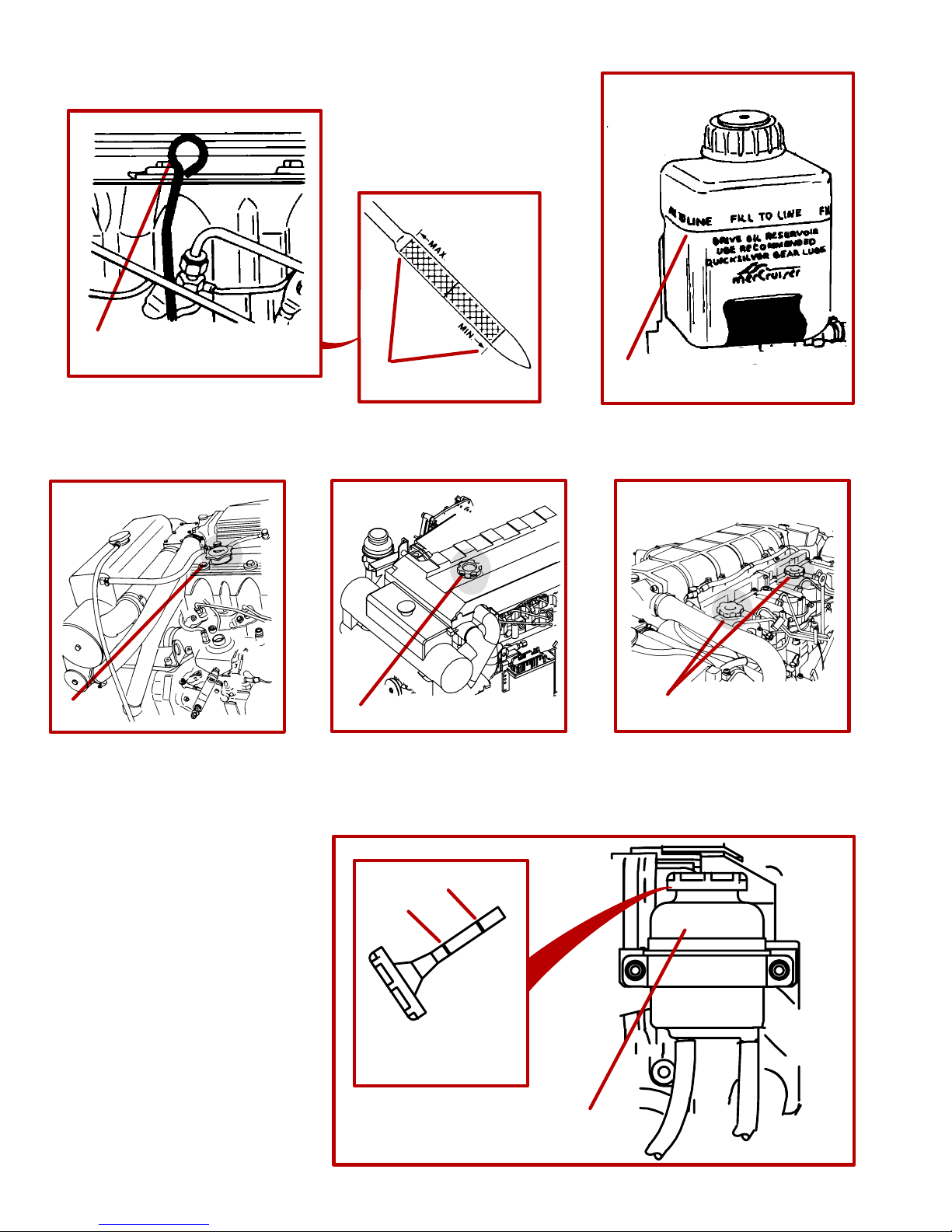
CD638
1
3A
71382
73322
3B
2
71380
75301
4
3C
74302
76394
68
6
B
A
71442
75297
5
Page 69

CD639
Checking Fluid Levels
CRANKCASE OIL
CAUTION
Avoid possible injury or damage to oil dipstick and internal engine components. Do not remove crankcase oil dipstick when engine is running. Stop the engine completely before removing or inserting dipstick.
If it becomes necessary to check oil level during operation, stop engine and allow 5 minutes for oil to drain into pan.
1 Remove dipstick. Wipe clean and reinstall into dipstick tube.
2 Remove dipstick and observe oil level. Oil must be between MIN and MAX marks on dipstick. If necessary,
add oil as follows.
3 Remove oil filler cap. Add specified oil to bring level up to, but not over, MAX mark on dipstick. Reinstall oil
filler cap.
A D3.6L and D4.2L
B D2.8L D-Tronic and D4.2L D-Tronic
C D4.2L LD
CD482
DRIVE UNIT OIL
NOTE: Oil level will fluctuate during operation. Oil level should be checked with cold engine before starting.
4 Check gear lube monitor oil level. Keep oil level at or near FULL line. Check for water at bottom of monitor
and/or if oil appears to be discolored, contact your Authorized MerCruiser Dealer immediately. Both conditions
may indicate a water leak somewhere in the drive unit.
IMPORTANT: If more than 2 fl. oz. (59ml) of Quicksilver Gear Lube are required to fill drive unit, a seal
may be leaking. Contact your Authorized MerCruiser Dealer for service. Damage to unit may occur due
to lack of lubrication.
CD270
POWER STEERING PUMP FLUID
IMPORTANT: If fluid is not visible in reservoir, contact your Authorized MerCruiser Dealer.
Power steering fluid must be checked with engine off and drive unit pointed straight back. Check with engine warm.
5 Remove fill cap/dipstick from reservoir. Wipe clean and reinstall into reservoir.
6 Remove fill cap/dipstick from reservoir and observe fluid level. Fluid must be between marks A and B on fill
cap/dipstick.
A MAXIMUM - FULL HOT Fluid Level -top Line. Fill to this level when fluid is hot. Do not overfill.
B MINIMUM - FULL COLD Fluid Level - Fill to this level when fluid is cold. Do not allow fluid to drop below this
level.
7 If necessary, add Quicksilver Power T rim and Steering Fluid or, if Quicksilver Power Trim and Steering Fluid
is not available, use Dexron III, to bring fluid to proper level. Replace fill cap/dipstick.
69
Page 70

CD640
3
2
72714
73320
1
71381
A
4
70
70979
5
B
73184
Page 71
CD166
ENGINE COOLANT
1 Before starting engine, check coolant level in coolant recovery bottle. Coolant level must be between the
“ADD” and “FULL” marks (on front of bottle). If level is low, remove fill cap from coolant recovery bottle and add
specified coolant as required. Refer to “Specifications” for proper coolant.
WARNING
Do not remove coolant tank cap when engine is hot. Coolant may discharge violently, causing severe
burns.
2 If coolant level in coolant recovery bottle was low:
• Inspect coolant recovery system for leaks.
• Inspect coolant tank cap gaskets for damage and replace if necessary.
• Also, the tank cap maintains pressure on the coolant tank. It may not be holding pressure properly. To have
cap tested, contact your Authorized MerCruiser Dealer.
CAUTION
If the coolant should get extremely low and the engine very hot, let the engine cool for approximately
15 minutes before adding coolant; then, with the engine running, add coolant slowly. Adding cold
coolant to a hot engine may crack the cylinder head or crankcase. Never use water alone.
3 Periodically, to ensure that coolant recovery system is functioning properly, you should allow engine to cool
and then slowly and carefully remove coolant tank cap. Coolant level must be to the bottom edge of the tank filler
neck. If coolant is low, add specified coolant as necessary to bring up to proper level. Refer to items 1 and 2
above.
CD620
POWER TRIM PUMP FLUID
Power trim pump fluid level must be checked with the drive unit in the full DOWN/IN position.
4 New trim pumps have a shipping “cap plug” in the reservoir fill neck. Ensure that this “cap plug” has been
removed. Remove and discard “cap plug” if present.
5 Remove cap and observe oil level. Level must be up to, but not over, the bottom edge of fill neck. Add Quicksil-
ver Power Trim and Steering Fluid, or use SAE 10W-30 or 10W-40 motor oil if available, as necessary to bring
oil to proper level . Replace reservoir cap.
A Reservoir Fill Neck
B Cap
71
Page 72

CD641
3B
3A
7A
7B
73322
A
B
4
70571
3C
3D
6A
72
75301
75298
74725
Page 73

CD642
Changing Fluids
See Maintenance Schedules for lubricant change interval. Lubricant should be changed before placing boat in
storage.
Power Trim or Power Steering fluids do not require changing.
Coolant in closed cooling system should be changed at specified intervals by your Authorized Mercury
MerCruiser Dealer.
CRANKCASE OIL AND FILTER - D3.6L, D4.2L, D2.8L D-TRONIC AND D4.2L D-TRONIC
IMPORTANT: Change oil when engine is warm from operation. Warm oil flows more freely, carrying
away more impurities. Use only recommended motor oil (refer to “Specifications”).
1 Start engine and allow it to warm up to normal operating temperature.
2 Stop engine and allow some time for oil to drain into oil pan (approximately 5 minutes).
3 Remove fitting from end of crankcase oil drain hose laying on top of engine.
A Fitting - D3.6L and D4.2L
B Oil drain hose - D3.6L and D4.2L
C Fitting - D2.8L D-Tronic and D4.2L D-Tronic
D Oil drain hose - D2.8L D-Tronic and D4.2L D-Tronic
4 Install crankcase oil pump onto threaded fitting of oil drain hose.
A Crankcase oil pump (Quicksilver Part Number 90265A2)
B Threaded Fitting
5 Pump oil out of crankcase into drain pan. When crankcase is empty, remove pump and reinstall crankcase
oil drain hose fitting. Tighten securely.
6 Remove and discard oil filter and sealing ring. Coat sealing ring on new filter with oil and install filter. Hand
tighten only, do not use a filter wrench.
7 Remove oil fill cap and refill engine with new oil (refer to “Specifications” for quantity and grade of oil).
A D3.6L and D4.2L
B D2.8L D-Tronic and D4.2L D-Tronic
IMPORTANT: When refilling engine with oil always use dipstick to determine how much oil is required.
CAUTION
Avoid possible injury, or damage to oil dipstick and internal engine components. Do not remove crankcase oil dipstick when engine is running. Stop the engine completely before removing or inserting dipstick.
IMPORTANT: On D3.6L and D4.2L Engines only: After oil change, pre-lubricate turbocharger and engine. T o do this, move the STOP switch toggle lever DOWN and hold in this position while you turn the
key switch to START position. Doing this TOGETHER turns the engine without starting it. DO NOT engage starter for more than 15 seconds; allow at least one minute cool down time before re-engaging
starter for another 15 seconds. Watch that starter does not overheat.
73
Page 74

CD643
4
3
76379
5
6
75297
74
76394
Page 75
CD644
CRANKCASE OIL AND FILTER - D4.2L LD
IMPORTANT: Change oil when engine is warm from operation. Warm oil flows more freely, carrying
away more impurities. Use only recommended motor oil (refer to “Specifications”).
1 Start engine and allow it to warm up to normal operating temperature.
2 Stop engine and allow some time for oil to drain into oil pan (approximately 5 minutes).
3 Remove fitting from end of crankcase oil pump. Attach a suitable hose for draining.
4 Pump oil out of crankcase into drain pan. When crankcase is empty, remove hose and reinstall crankcase
oil pump fitting. Tighten securely.
5 Remove and discard oil filter and sealing ring. Coat sealing ring on new filter with oil and install filter. Hand
tighten only, do not use a filter wrench.
6 Remove oil fill cap and refill engine with new oil (refer to “Specifications” for quantity and grade of oil).
IMPORTANT: When refilling engine with oil always use dipstick to determine how much oil is required.
CAUTION
Avoid possible injury, or damage to oil dipstick and internal engine components. Do not remove crankcase oil dipstick when engine is running. Stop the engine completely before removing or inserting dipstick.
IMPORTANT: After oil change, pre-lubricate turbocharger and engine. T o do this, move the ST OP switch
toggle lever DOWN and hold in this position while you turn the key switch to START position. Doing this
TOGETHER turns the engine without starting it. DO NOT engage starter for more than 15 seconds; allow
at least one minute cool down time before re-engaging starter for another 15 seconds. Watch that starter
does not overheat.
75
Page 76

CD645
1A
6
4
74302
1B
70121
75301
5
74732
1C
76380
2
70568
76
3A
72522
3B
70581
Page 77

CD646
DRIVE UNIT OIL
1 Remove gear lube monitor bottle from bracket. Empty contents into suitable container. Install monitor in
bracket.
A D3.6L and D4.2L
B D2.8L D-Tronic and D4.2L D-Tronic
C D4.2L LD
2 Bravo One Models: Remove propeller, place drive unit in full DOWN/IN position, remove OIL FILL/DRAIN
SCREW and sealing washer, and drain oil.
3 All Other Models: Place drive unit in full UP/OUT position, remove OIL FILL/DRAIN SCREW and sealing
washer, and drain oil.
A Bravo Three
B Bravo Two
4 Remove OIL VENT screw and sealing washer. Allow oil to drain completely.
IMPORTANT: If any water drained from OIL FILL/DRAIN hole, or if oil appears milky, drive unit is leaking
and should be checked immediately by your Authorized MerCruiser Dealer.
5 Lower drive unit so propeller shaft is level. Fill drive unit, through OIL FILL/DRAIN hole, with Specified Gear
Lube until an air-free stream of lubricant flows from OIL VENT hole.
IMPORTANT: Use only Quicksilver High Performance Gear Lube in drive unit.
6 Install OIL VENT screw and sealing washer.
7 Continue to pump gear lube into the gear lube monitor circuit until gear lube appears in the gear lube monitor.
8 Fill monitor to FILL mark. Lubricate O-ring on neck with sterndrive oil. Install cap; do not overtighten.
9 Remove pump from OIL FILL/DRAIN hole. Quickly install sealing washer and OIL FILL/DRAIN screw. Tighten
securely.
10Bravo One Models: Grease propeller shaft heavily, with specified lubricant (Refer to “Propeller Installation”
if necessary). Reinstall propeller and torque nut to 55 lb. ft. (75 N
⋅m) MINIMUM.
11 Recheck oil level after first use.
IMPORTANT: Oil level in gear lube monitor will rise and fall during drive operation; always check oil level
when drive is cool and engine is shut down.
77
Page 78

CD647
C
B
A
1
71267
3
5
2
2
71588
74301
4
4
70113
6
7
74085
78
Page 79
CD648
Air Filter Cleaning/Replacement
1 Disconnect crankcase vent hose from end of air cleaner. Carefully remove air cleaner foam element from
around air intake screen housing mounted on turbocharger inlet. Wash foam element in warm water and detergent until clean.
A Crankcase Vent Hose
B Foam Element
C Intake Screen Housing
CAUTION
Avoid potential fire hazards and injury, or damage to polyester foam element. Do not clean foam element in petroleum based solvents or cleaners.
IMPORTANT: No treatment (such as partial oil saturation) is required or recommended on air cleaner
foam element prior to use. Use element clean and dry for proper filtration.
Allow element to completely dry before use and install around air intake screen. Replace the foam element if
it is deteriorated or torn. (Refer to “Maintenance Schedules” for replacement interval under normal conditions.)
IMPORTANT: To prevent unfiltered air from entering the engine be certain that all of the air intake screen
is covered by the foam element when installed.
CD649
Drive Belts - All Engines, Except D3.6L Engines
All drive belts must be periodically inspected for tension and condition (excessive wear, cracks, fraying, or glazed
surfaces).
If any drive belts need replacement or tension needs adjustment, see your Authorized Mercury MerCruiser
Dealer.
IMPORTANT: On models with dual-row pulleys and dual belts always inspect both belts. Never renew
just one of the two belts driving the alternator and engine water circulating pump. Always replace both
belts as a pair, preferably as a “matched pair.”
WARNING
Make sure engine is shut off and ignition key is removed before inspecting belts.
ALTERNATOR DRIVE BELT AND ENGINE WATER CIRCULATING PUMP BELT, OR BELTS
2 Inspect drive belt, or belts, for excessive wear or damage.
3 Check belt tension by depressing upper strand of belt, with moderate hand pressure, at point shown. Belt
should move no more than 3/16 in. (5 mm) either way.
POWER STEERING PUMP BELT
4 Inspect drive belt for excessive wear or damage.
5 Check belt tension by depressing upper strand of belt, with moderate hand pressure, at point shown. Belt
should move no more than 3/16 in. (5 mm) either way.
VACUUM PUMP BELT (IF SO EQUIPPED)
6 Inspect drive belt for excessive wear or damage.
7 Check belt tension by depressing upper strand of belt, with moderate hand pressure, at point shown. Belt
should move no more than 3/16 in. (5 mm) either way.
79
Page 80

CD650
4
3
70355 70062
3
B
2
2
1C
1B
13
74095
1A
73320
5
10
A
74301
A
B
71443
80
Page 81

CD651
Drive Belts - D3.6L Engines
WARNING
Make sure engine is shut off and ignition key is removed before inspecting belts.
1 All drive belts must be periodically inspected for tension and condition (excessive wear, cracks, fraying, or
glazed surfaces).
A Alternator Belt/Water Circulating Pump Belt
B Power Steering Pump Belt
C Vacuum Pump Belt (If so equipped)
2 Check belt tension by depressing belt, with moderate hand pressure, at points shown. Belt should depress
3/16 inch (5 mm).
ALTERNATOR BELT
CAUTION
Avoid water entering boat. If seawater pump hoses are to be removed with boat in the water, seacock
(if so equipped) must be closed, or water inlet hose must be disconnected and plugged to prevent
water from flowing into boat.
3 Close seacock, if so equipped, or plug seawater inlet hose.
4 Remove seawater hoses at seawater pump. Remove power steering belt.
5 Loosen mounting bolt. Loosen nut and tensioning bolt. Pivot alternator until belt can be removed.
A Mounting bolt
B Tensioning bolt
6 Remove old belt and install new belt. Adjust belt tension by pivoting alternator. When tension is correct, retigh-
ten all fasteners securely.
7 Reinstall and adjust tension of power steering belt.
8 Reconnect seawater hoses to seawater pump. Tighten hose clamps securely.
9 Open seacock, if so equipped, or remove plug from seawater inlet hose and reconnect hose. Tighten hose
clamps securely.
POWER STEERING PUMP BELT
10Loosen mounting bolt. Pivot pump by loosening nut and turning tensioning bolt until belt can be removed.
A Mounting bolt
B Tensioning bolt
11 Remove old belt and install new belt. Pivot pump using tensioning bolt to adjust belt tension.
12When tension is correct, retighten all fasteners securely.
VACUUM PUMP BELT
13 Remove power steering belt.
14 Loosen the vacuum pump mounting and tensioning screws, behind the bracket.
15 Appropriately pry or move the vacuum pump to loosen belt. Remove old belt.
16 Install new vacuum pump belt and adjust tension. Torque mounting and tensioning screws to 15 lb-ft (21 Nm).
81
Page 82

CD652
5A
1
71903
3
71904
75332
2
71901
5B
76405
4
74732
6
8
70558
73346
70094
9
71346
10
71347
82
Page 83

CA286
Lubrication
STEERING SYSTEM
1 If Steering Cable Has Grease Fittings: With cable fully retracted into cable housing, lubricate fitting with
2-4-C Marine Lubricant with Teflon.
WARNING
Do not grease steering cable while extended. Hydraulic lock could occur and cause loss of steering
control.
NOTE: If steering cable does not have grease fitting, inner wire of cable cannot be greased.
2 With steering cable fully extended lubricate exposed part of cable with Special Lubricant 101.
3 Lubricate steering system pivot points with SAE 30W motor oil.
On dual engine boats, lubricate all pivot points, including tie bar pivot points, with SAE 30W motor oil.
CA72
Shift Cable
4 Lubricate pivot points with SAE 30W motor oil.
CD674
THROTTLE CABLE
5 Lubricate pivot points with SAE 30W motor oil.
A D2.8L D-Tronic and D4.2L D-Tronic
B D3.6L, D4.2L and D4.2L LD
CA525
DRIVE UNIT AND TRANSOM ASSEMBLY
6 Lubricate gimbal bearing by applying approximately 8-10 pumps of grease from a typical hand-operated
grease gun using Quicksilver U-Joint and Gimbal Bearing Grease.
7 For propeller shaft lubrication, see Propeller.
CB776
ENGINE COUPLER
8 Lubricate engine coupler splines through grease fittings on coupler by applying approximately 8-10 pumps
of grease from a typical hand-operated grease gun using Quicksilver Engine Coupler Spline Grease. If boat is
operated at idle for prolonged periods of time, couple should be lubricated every 50 hours.
CB777
DRIVE SHAFT EXTENSION MODELS
9 Lubricate drive shaft grease fittings, at transom end, by applying approximately 3 - 4 pumps of grease from
a typical hand-operated grease gun using Quicksilver U-joint and Gimbal Bearing Grease.
10Lubricate drive shaft grease fittings, at engine end, by applying approximately 3 - 4 pumps of grease from
a typical hand-operated grease gun using Quicksilver U-joint and Gimbal Bearing Grease.
83
Page 84

CD304
A
B
C
1
E
F
1
70355
1
70062
H
D
71362
3
4
70565
71353
5
84
74733
73320
G
H
2
72055
Page 85

CE376
Cleaning Quicksilver Seawater Strainer
NOTE: Refer to manufacturers instructions if equipped with other than a Quicksilver seawater strainer.
CAUTION
When cleaning seawater strainer, close seacock, if so equipped. If boat is not equipped with a seacock,
remove and plug seawater inlet hose to prevent a siphoning action that may occur, allowing seawater
to flow from the drain holes or removed hoses.
1 With engine off, close seacock if so equipped, or remove and plug seawater inlet hose. Remove screws and
washers, and cover . Remove strainer, drain plug and washer, and clean any debris from strainer housing; flush
both strainer and housing with clean water . Check gasket - replace when necessary (if it leaks). Reinstall drain
plug and washer. Reattach cover with screws and washers. Prior to starting engine, open seacock if so equipped,
or remove plug from seawater inlet hose and reconnect. Tighten hose clamps securely. After starting engine,
check for leaks, and/or air in system (which would indicate an external leak).
A Screws and Washers
B Cover
C Strainer
D Drain Plug and Washer
E Housing
F Gasket
CD172
Flushing Seawater Cooling System
To prevent silt and/or salt buildup in the seawater circuit of cooling system, flush with tap water at specified
Intervals.
WARNING
When flushing, be certain the area around propeller is clear, and no one is standing nearby. To avoid
possible injury, remove propeller.
CAUTION
Do not run engine above 1500 RPM when flushing. Suction created by seawater pickup pump may
collapse flushing hose, causing engine to overheat.
CAUTION
Watch temperature gauge on dash to ensure that engine does not overheat.
2 Install Quicksilver flushing attachment (G) (or equivalent) over water intake openings in gear housing.
NOTE: If flushing cooling system with boat in water, raise drive unit to TRAILER position, install flushing attachment and lower drive unit to full down/in position.
3 Connect hose (H) between flushing attachment and water tap.
4 With drive unit in normal operating position, partially open water tap (about 1/2 maximum). Place remote con-
trol in NEUTRAL, idle speed position and start engine. Operate engine at idle speed, in NEUTRAL, for about
10 minutes, or until discharge water is clear. Stop engine, shut off water and remove flushing attachment.
5 The closed section of cooling system that contains coolant does not need to be flushed. Coolant is changed
at specified intervals. Refer to “Maintenance Schedule.”
85
Page 86

CD653
2A
3A
4A
714441
74726
5
71371
2B
3B
4B
76390
76379
86
Page 87

CE406
Fuel System
CAUTION
Absolute cleanliness is required for work on the fuel system, fuel injection components have very
close tolerances. Even minute particles of dirt or small amounts of water can impair the function of the
fuel injection system.
FUEL TANK CLEANING AND FLUSHING
IMPORTANT: Diesel fuel should not be left in tank during winter storage, as an accumulation of rust,
sludge and wax residue will form.
1 Refer to boat manufacturer’s instructions and clean fuel tank at specified intervals. Unless specified other-
wise, flush and clean diesel fuel tank every 1000 hours or 5 years, whichever occurs first.
CD654
HAND PUMP/PRIMER
2 A plunger-type of hand pump/primer is located on the fuel filter bracket and is used to: (1) refill fuel system
if system was run dry; (2) refill fuel filter when changing filter; or (3) to prime the fuel system if engine has not
been run for a while. To operate the hand pump/primer, move the plunger (upper portion) up and down as
needed.
A D3.6L and D4.2L Models.
B D2.8L D-Tronic, D4.2L D-Tronic and D4.2L LD Models.
CD655
PRIMING FUEL SYSTEM
3 Prime engine if it has not been run for a while or if engine will not start. Move the hand pump/primer plunger
up and down several times as previously outlined. Attempt to start engine.
A D3.6L and D4.2L Models.
B D2.8L D-Tronic, D4.2L D-Tronic and D4.2L LD Models.
CD656
FILLING FUEL FILTER
NOTE: Follow this procedure after installing new filter or if fuel has been drained from filter checking for water.
4 Loosen bleed screw on fuel filter bracket. As previously outlined, move plunger on hand pump/primer up and
down repeatedly, until an air free stream of fuel flows from bleed screw. Filter is full when this occurs. Tighten
bleed screw.
A D3.6L and D4.2L Models.
B D2.8L D-Tronic, D4.2L D-Tronic and D4.2L LD Models.
CD657
FILLING (BLEEDING) FUEL SYSTEM
NOTE: Follow this procedure if fuel system was run dry or if part of fuel system was drained for a service function.
Fill fuel system up to the point that fuel filter is full following previous procedure (Filling Fuel Filter); then, ensure
that bleed screw on fuel filter bracket is closed.
5 On D3.6L, D4.2L and D4.2L LD Only: Loosen, DO NOT REMOVE, bleed screw on fuel injection pump (lo-
cated between fuel line connection fittings on injection pump). Continue to repeatedly move plunger on hand
pump/primer, until an air-free stream of fuel flows from injection pump bleed screw. Tighten bleed screw.
87
Page 88

CD658
1A
74726
1B
76379
a
b
88
1
74726
Page 89

CD659
DRAINING WATER SEPARATING FUEL FILTER
WARNING
Be careful when draining water separating fuel filter. Diesel fuel is flammable. Be sure ignition key is
OFF. Do not allow fuel to contact any hot surfaces which may cause it to ignite. Do not allow sources
of open flame in the area. Wipe up any spilled fuel immediately. Dispose of fuel soaked rags, paper,
etc. in an appropriate air tight, fire retardant container. Fuel soaked items may spontaneously ignite
and result in a fire hazard which could cause serious bodily injury or death.
1 The filter (a) can be drained of water and small dirt particles by opening drain cock at bottom of filter. Open
by turning the drain (b) counterclockwise (as viewed from the bottom of the filter). Drain until fuel is clear in ap-
pearance. Close drain by turning clockwise. Tighten securely. Fill fuel filter as previously outlined.
A D3.6L and D4.2L Models.
B D2.8L D-Tronic, D4.2L D-Tronic and D4.2L LD Models.
NOTE: To ensure complete draining, in warm weather open the water bleed valve before starting daily operations. In cold weather , where there is a possibility that the condensed water will freeze, drain the filter shortly after
the end of daily operations.
89
Page 90

CD660
A
76114
C
D
B
1
74731
C
B
A
2
90
76379
D
Page 91

CD661
REPLACING WATER SEPARATING FUEL FILTER
CAUTION
Any water entering the fuel injection system will disable the system. Check for water in water
separating fuel filter before startup, daily.
CAUTION
If water should enter the fuel injection system, take unit to an Authorized MerCruiser Dealer
IMMEDIATELY, so that corrosion and rusting of the injectors and other components can be avoided.
WARNING
Be careful when changing water separating fuel filter. Diesel fuel is flammable. Be sure ignition key is
OFF. Do not allow fuel to contact any hot surfaces which may cause it to ignite. Do no tallow sources
of open flame in the area. Wipe up any spilled fuel immediately. Dispose of fuel soaked rags, paper,
etc. in an appropriate air tight, fire retardant container. Fuel soaked items may spontaneously ignite
and result in a fire hazard which could cause serious bodily injury or death.
1 On D3.6L, D4.2L, D2.8L D-Tronic and D4.2L D-Tronic Models:
A Twist locking ring by hand. Remove water separating fuel filter and sealing ring from mounting bracket. Do
not use a filter wrench.
B Remove the drain cap and O-ring from bottom of the existing filter. Install on new filter.
C Coat sealing ring on new filter with clean motor oil.
D Align filter to bracket. Twist locking ring by hand to secure filter to bracket. Do not use a filter wrench.
E Check that bottom drain cap is securely tightened. Fill fuel filter as explained previously. Check filter and drain
cap for fuel leaks.
2 On D4.2L LD Models:
A Remove and discard water separating fuel filter and sealing ring from mounting bracket.
B Coat sealing ring on new filter with clean motor oil.
C Thread filter onto bracket and tighten securely by hand. Do not use a filter wrench.
D Check that bottom drain cap is securely tightened. Fill fuel filter as explained previously . Check filter and drain
cap for fuel leaks.
WARNING
Make sure no leaks exist before closing engine hatch.
3 All Models: Start and run engine. Check filter connection for fuel leaks. If leaks exist, recheck filter installa-
tion. If leaks continue, stop engine immediately and contact your Authorized Mercury MerCruiser Dealer.
91
Page 92

CD677
1
73522
71366
BRAVO ONE
BRAVO TWO
75492
2
4
3
71560
70561
92
Page 93

CB66
Seawater Pump Impeller
This maintenance should be performed by an Authorized MerCruiser Dealer.
1 Seawater pump impeller should be inspected whenever insufficient seawater flow is suspected (if operating
temperature exceeds normal range).
CB421
Propellers (Bravo One and Two)
WARNING
Avoid Injury: Remote Control must be in NEUTRAL and ignition key removed from switch before removing and/or installing propeller.
WARNING
Avoid Injury: Place a block of wood between anti-ventilation plate and propeller to protect hands from
propeller blades and to prevent propeller from rotating when removing propeller nut.
WARNING
Avoid Injury: Periodically check propeller nut for tightness during boating season. A minimum of 55
lb-ft (75 Nm) torque is required.
CA78
REMOVAL (BRAVO ONE AND TWO)
2 Place wood block between propeller blade and anti-ventilation plate to prevent rotation. Straighten bent tabs
on tab washer.
3 Turn propeller shaft nut counterclockwise to remove nut.
4 Slide tab washer, spline washer, propeller and thrust hub off propeller shaft.
CA79
REPAIR
Some damaged propellers can be repaired. See your dealer.
93
Page 94

CB722
75492
BRAVO ONE
BRAVO TWO
3
1
2
4
5A
7
5B
70561
94
Page 95

CD513
INSTALLATION (BRAVO ONE AND TWO)
1 Apply a liberal coat of one of the following Quicksilver lubricants to propeller shaft: Anti-Corrosion Grease,
Special Lubricant 101, or 2-4-C Marine Lubricant with Teflon.
2 Slide thrust hub into propeller hub, with stepped side toward propeller hub.
3 Bravo One: Install Flo-Torq II Drive Hub with drive sleeve.
NOTE: The drive sleeve is tapered and will slide fully into the propeller as the nut is tightened and properly
torqued.
4 Align splines and place propeller on propeller shaft.
5 Install final attaching hardware.
IMPORTANT: If reusing locking tab washer, carefully inspect tabs for cracks or other damage. Replace
tab washer if condition is questionable.
A Bravo One: Install drive sleeve adaptor and locking tab washer (Flo-Torq II Drive Hub).
B Bravo Two: Install spline washer and locking tab washer.
6 Place wood block between propeller blade and anti-ventilation plate to prevent rotation.
7 Install propeller nut.
A Torque nut to a minimum of 55 lb-ft (75 Nm).
IMPORTANT: Installation is correct when at least 2 threads of propeller shaft are exposed through propeller nut.
B Continue to tighten propeller nut until 3 tabs on tab washer align with three grooves on spline washer or
drive sleeve adaptor, if not already aligned.
C Bend three tabs on tab washer down into grooves.
D After first use, bend the three tabs straight. Repeat steps 7A, 7B and 7C.
E Check propeller at least every 20 hours of operation.
CAUTION
Avoid loss of propeller (propulsion). Do not operate with a propeller nut that is improperly tightened.
95
Page 96

CD355
4
2
72239
6
7
8
96
9
10
11
12
72239
Page 97

CD356
Propellers (Bravo Three)
WARNING
Avoid Injury: Remote Control must be in NEUTRAL and ignition key removed from switch before
removing and/or installing propellers.
WARNING
Avoid Injury: Place a block of wood between splash-plate and propellers to protect hands from
propeller blades and to prevent propellers from rotating when removing propeller nuts.
CAUTION
Avoid Injury: Do not operate with loose propeller. Periodically check propeller nuts for tightness
during boating season.
REMOVAL (BRAVO THREE)
1 Place wood block between propeller blades and anti-ventilation plate to prevent rotation.
2 Turn aft propeller shaft nut counterclockwise to remove nut.
3 Slide propeller and thrust hub off propeller shaft.
4 Turn front propeller shaft nut counterclockwise to remove nut.
5 Slide propeller and thrust hub off propeller shaft.
CA79
REPAIR
Some damaged propellers can be repaired. See your dealer.
CB721
INSTALLATION (BRAVO THREE)
6 Apply a liberal coat of one of the following Quicksilver lubricants to both propeller shafts: Special Lubricant
101, 2-4-C Marine Lubricant with Teflon, or Anti-Corrosion Grease.
7 Slide forward thrust hub onto propeller shaft, with tapered side toward propeller hub (toward end of shaft).
8 Align splines and place propeller on propeller shaft.
9 Install propeller nut. Tighten nut securely. A minimum of 100 lb-ft (136 Nm) torque is required. Check propeller
at least after 20 hours of operation. Do not operate with loose propeller.
10Slide aft thrust hub onto propeller shaft, with tapered side toward propeller hub (toward end of shaft).
11 Align splines and place propeller on propeller shaft.
12Install propeller nut. Tighten nut securely. A minimum of 60 lb-ft (81 Nm) torque is required. Check propeller
at least after 20 hours of operation. Do not operate with loose propeller.
Avoid loss of propeller (propulsion). Do not operate with a propeller nut that is improperly tightened.
CAUTION
97
Page 98

CD662
1
A
74732
B
71367
1
73327
71368
98
Page 99

CD119
Corrosion And Corrosion Protection
INTERNAL COMPONENTS
1 There are anodes as part of the intercooler and heat exchanger systems, which serves as a sacrificial anodes.
Replace when eroded more than 50%; check at least once yearly.
A Length When New - 3/4 in. (19mm)
B Diameter When New - 5/8 in. (15mm)
99
Page 100

CD231
A
1
73919
6
72032
B
5
71966
3
100
70578
71176
4
70577
2
70055
 Loading...