

Page 1

Table of Contents
Introduction 4
Instrument Cluster 10
Warning and control lights 10
Gauges 16
Entertainment Systems 19
AM/FM stereo cassette with CD 19
AM/FM stereo with CD 34
Climate Controls 44
Manual heating and air conditioning 44
Lights 47
Headlamps 47
Turn signal control 50
Bulb replacement 51
Driver Controls 57
Windshield wiper/washer control 57
Steering wheel adjustment 59
Power windows 60
Mirrors 60
Speed control 61
Message center 66
1
Page 2

Table of Contents
Locks and Security 70
Keys 70
Locks 70
Anti-theft system 71
Seating and Safety Restraints 79
Seating 79
Safety restraints 83
Air bags 94
Child restraints 102
Driving 112
Starting 112
Brakes 116
Traction control/AdvanceTrac 119
Transmission operation 120
Vehicle loading 129
Trailer towing 130
Roadside Emergencies 134
Getting roadside assistance 134
Hazard flasher switch 135
Fuel pump shut-off switch 135
Fuses and relays 136
Changing tires 142
Jump starting 145
Wrecker towing 151
2
Page 3

Table of Contents
Customer Assistance 152
Reporting safety defects (U.S. only) 160
Cleaning 161
Maintenance and Specifications 167
Engine compartment 170
Engine oil 172
Battery 175
Fuel information 182
Part numbers 198
Refill capacities 199
Lubricant specifications 200
Accessories 204
Index 207
All rights reserved. Reproduction by any means, electronic or mechanical
including photocopying, recording or by any information storage and retrieval
system or translation in whole or part is not permitted without written
authorization from Ford Motor Company. Ford may change the contents without
notice and without incurring obligation.
Copyright © 2002 Ford Motor Company
3
Page 4

Introduction
The following warning may be required by California law:
CALIFORNIA Proposition 65 Warning
WARNING: Engine exhaust, some of its constituents, and
certain vehicle components contain or emit chemicals known to
the State of California to cause cancer and birth defects or other
reproductive harm. In addition, certain fluids contained in vehicles and
certain products of component wear contain or emit chemicals known
to the State of California to cause cancer and birth defects or other
reproductive harm.
CONGRATULATIONS
Congratulations on acquiring your new Mercury. Please take the time to
get well acquainted with your vehicle by reading this handbook. The
more you know and understand about your vehicle the greater the safety
and pleasure you will derive from driving it.
For more information on Ford Motor Company and its products visit the
following website:
• In the United States: www.ford.com
• In Canada: www.ford.ca
• In Mexico: www.ford.com.mx
• In Australia: www.ford.com.au
Additional owner information is given in separate publications.
This Owner’s Guide describes every option and model variant available
and therefore some of the items covered may not apply to your
particular vehicle. Furthermore, due to printing cycles it may describe
options before they are generally available.
Remember to pass on the Owner’s Guide when reselling the vehicle. It is
an integral part of the vehicle.
4
Page 5
Introduction
Fuel pump shut-off switch In the event of an accident the
safety switch will automatically cut off the fuel supply to the
engine. The switch can also be activated through sudden vibration (e.g.
collision when parking). To reset the switch, refer to the Fuel pump
shut-off switch in the Roadside emergencies chapter.
SAFETY AND ENVIRONMENT PROTECTION
Warning symbols in this guide
How can you reduce the risk of personal injury and prevent possible
damage to others, your vehicle and its equipment? In this guide, answers
to such questions are contained in comments highlighted by the warning
triangle symbol. These comments should be read and observed.
Warning symbols on your vehicle
When you see this symbol, it is
imperative that you consult the
relevant section of this guide before
touching or attempting adjustment
of any kind.
5
Page 6

Introduction
Protecting the environment
We must all play our part in
protecting the environment. Correct
vehicle usage and the authorized
disposal of waste cleaning and
lubrication materials are significant
steps towards this aim. Information in this respect is highlighted in this
guide with the tree symbol.
BREAKING-IN YOUR VEHICLE
There are no particular guidelines for breaking-in your vehicle. During
the first 1,600 km (1,000 miles) of driving, vary speeds frequently. This is
recommended to give the moving parts a chance to break in.
SPECIAL NOTICES
Emission warranty
The New Vehicle Limited Warranty includes Bumper-to-Bumper
Coverage, Safety Restraint Coverage, Corrosion Coverage, and 7.3L
Power Stroke Diesel Engine Coverage. In addition, your vehicle is eligible
for Emissions Defect and Emissions Performance Warranties. For a
detailed description of what is covered and what is not covered, refer to
the Warranty Guide that is provided to you along with your Owner’s
Guide.
6
Page 7

Introduction
Special instructions
For your added safety, your vehicle is fitted with sophisticated electronic
controls.
By operating other electronic equipment (e.g. mobile telephone
without exterior aerial) electromagnetic fields can occur which
can cause malfunctions of the vehicle electronics. Therefore you should
observe the instructions of the equipment manufacturers.
Please read the section Air bag in the Seating and safety
restraints chapter. Failure to follow the specific warnings and
instructions could result in personal injury.
Front seat mounted rear-facing child or infant seats should
NEVER be used in front of a passenger side air bag.
MIDDLE EAST/NORTH AFRICA VEHICLE SPECIFIC INFORMATION
For your particular global region, your vehicle may be equipped with
features and options that are different from the ones that are described
in this Owner Guide; therefore, a supplement has been supplied that
complements this book. By referring to the pages in the provided
supplement, you can properly identify those features, recommendations
and specifications that are unique to your vehicle. Refer to this Owner
Guide for all other required information and warnings.
7
Page 8
Introduction
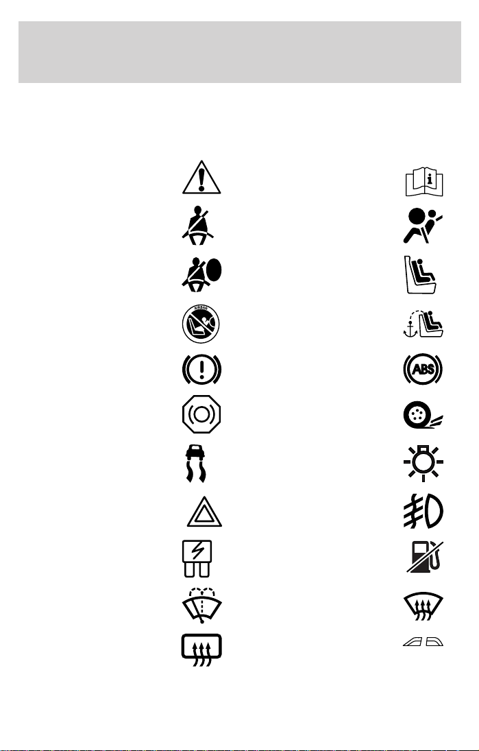
These are some of the symbols you may see on your vehicle.
Vehicle Symbol Glossary
Safety Alert
Fasten Safety Belt Air Bag-Front
Air Bag-Side Child Seat
Child Seat Installation
Warning
Brake System Anti-Lock Brake System
Brake Fluid Non-Petroleum Based
AdvanceTrac Master Lighting Switch
Hazard Warning Flasher Fog Lamps-Front
Fuse Compartment Fuel Pump Reset
See Owner’s Guide
Child Seat Tether
Anchorage
Traction Control
Windshield Wash/Wipe
Rear Window
Defrost/Demist
8
Windshield
Defrost/Demist
Power Windows
Front/Rear
Page 9
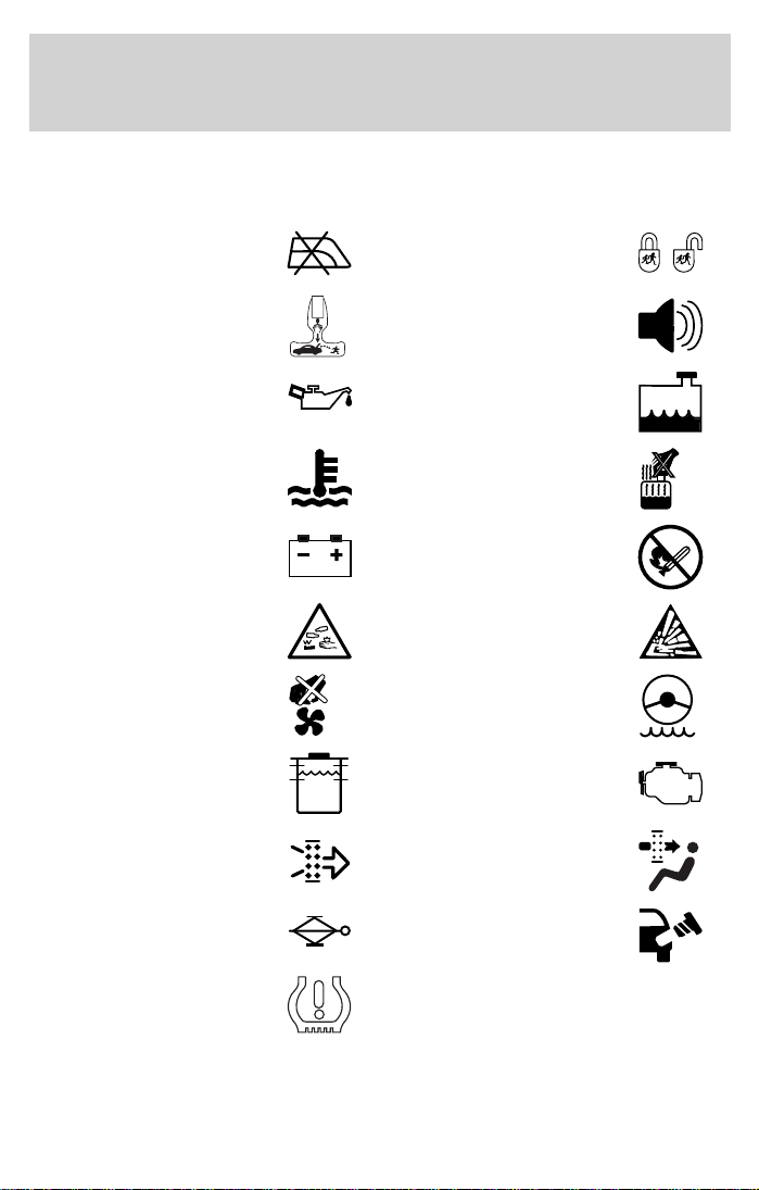
Vehicle Symbol Glossary
Introduction
Power Window Lockout
Child Safety Door
Lock/Unlock
Interior Luggage
Compartment Release
Panic Alarm
Symbol
Engine Oil Engine Coolant
Engine Coolant
Temperature
Battery
Do Not Open When Hot
Avoid Smoking, Flames,
or Sparks
Battery Acid Explosive Gas
Fan Warning Power Steering Fluid
Maintain Correct Fluid
Level
Engine Air Filter
MAX
MIN
Emission System
Passenger Compartment
Air Filter
Jack Check fuel cap
Low tire warning
9
Page 10
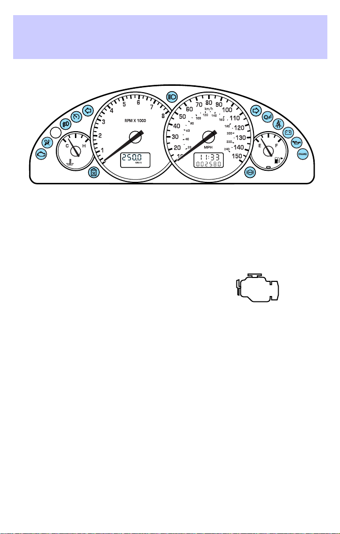
Instrument Cluster
WARNING LIGHTS AND CHIMES
Warning lights and gauges can alert you to a vehicle condition that may
become serious enough to cause expensive repairs. A warning light may
illuminate when a problem exists with one of your vehicle’s functions.
Many lights will illuminate when you start your vehicle to make sure the
bulb works. If any light remains on after starting the vehicle, have
the respective system inspected immediately.
Check engine
Illuminates briefly to ensure the
system is functional. If it comes on
after the engine is started, one of
the engine’s emission control
systems may be malfunctioning. The light may illuminate without a
driveability concern being noted and will not require towing.
Light turns on solid:
Temporary malfunctions may cause your light to illuminate. Examples
are:
• The vehicle has run out of fuel.
• Poor fuel quality or water in the fuel.
• The fuel cap may not have been properly installed and securely
tightened.
These temporary malfunctions can be corrected by filling the fuel tank
with high quality fuel of the recommended octane and/or properly
installing and securely tightening the fuel cap. After three driving cycles
without these or any other temporary malfunctions present, the light
should turn off. (A driving cycle consists of a cold engine startup
followed by mixed city/highway driving.) No additional vehicle service is
required.
10
Page 11
Instrument Cluster
If the light remains on, have your vehicle serviced at the first available
opportunity.
Light is blinking:
Engine misfire is occurring which could damage your catalytic converter.
You should drive in a moderate fashion (avoid heavy acceleration and
deceleration) and have your vehicle serviced at the first available
opportunity.
Under engine misfire conditions, excessive exhaust temperatures
could damage the catalytic converter, the fuel system, interior
floor coverings or other vehicle components, possibly causing a
fire.
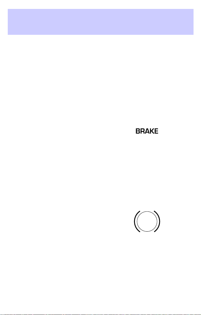
Brake system warning
To confirm the brake system
warning light is functional, it will
momentarily illuminate when the
ignition is turned to the ON position (alternatively for some vehicles
when the ignition is moved from the ON position to START position, the
light will momentarily illuminate prior to reaching the START position).
It also illuminates if the parking brake is engaged. If the brake system
warning light does not illuminate as described, seek service immediately.
Illumination after the parking brake is released indicates low brake fluid
level or a brake system malfunction and the brake system should be
serviced immediately by a qualified technician. Refer to Brakes in the
Driving chapter for more information.
Anti-lock brake system (ABS)
To confirm the anti-lock brake
system (ABS) warning light is
functional it will momentarily
illuminate when the ignition is
turned to the ON position
(alternatively for some vehicles when the ignition is moved from the ON
position to the START position, the light will momentarily illuminate just
prior to reaching the START position). If the light remains on, continues
to flash or fails to illuminate, have the ABS serviced immediately. If the
ABS light remains on, it means the anti-lock brake system has
malfunctioned and is disabled, however, the normal brake system will
still function unless the brake warning light also remains illuminated and
parking brake is off. Refer to Brakes in the Driving chapter for more
information.
ABS
11
Page 12
Instrument Cluster
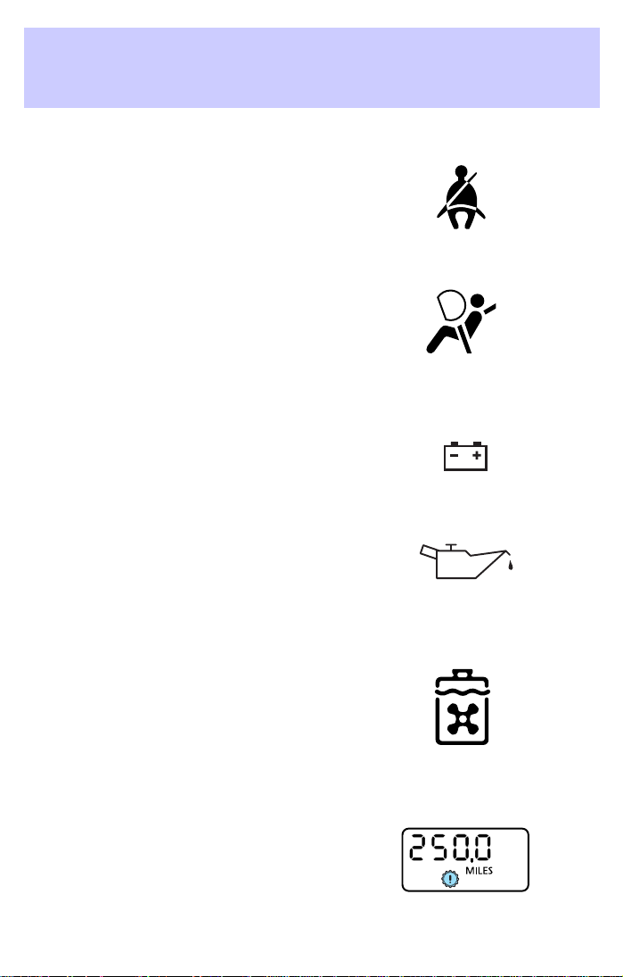
Safety belt
Illuminates to remind you to fasten
your safety belts. For more
information, refer to the Seating
and safety restraints chapter.
Air bag readiness
Illuminates to confirm that the air
bags (front and side) are
operational. If the light fails to
illuminate, continues to flash or
remains on, have the system
serviced immediately.
Charging system
Illuminates when the battery is not
charging properly.
Engine oil pressure
Illuminates when the oil pressure
falls below the normal range. Check
the oil level and add oil if needed.
Refer to Engine oil in the
Maintenance and specifications chapter.
Check coolant (if equipped)
Illuminates when the coolant level in
the coolant reservoir is low and
more needs to be added. For more
information on adding engine
coolant, refer to Engine coolant in
the Maintenance and specifications chapter.
Check transaxle
Illuminates when a transaxle
problem has been detected and
shifting may be restricted. If this
lamp remains on, have your vehicle
serviced immediately.
12
Page 13
Instrument Cluster
Traction ControlY active
Illuminates when the Traction
Controly system is active. It will be
lit for a minimum of four seconds or
for the duration of the Traction
Controly event.
For more information, refer to the Driving chapter.
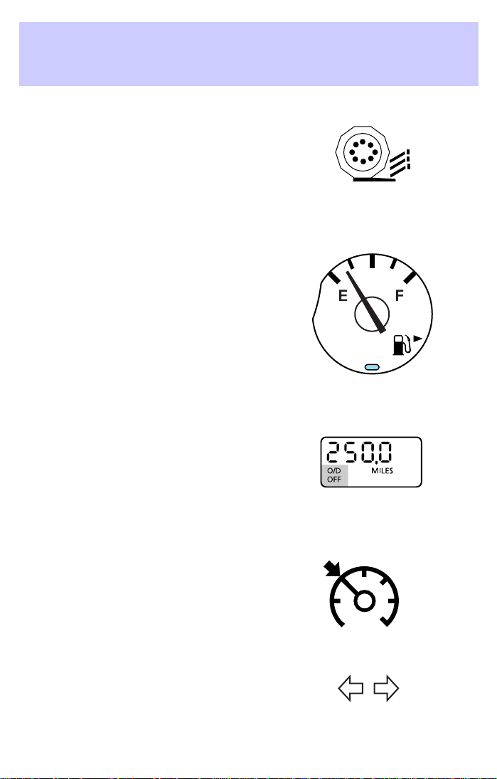
Low fuel
Illuminates when the fuel level in
the fuel tank is at, or near, empty
(refer to Fuel gauge in this chapter
for more information). When
refueling, after the light comes on,
the amount of fuel that is added will
be less than the advertised capacity
since there is fuel still in the tank.
O/D off (if equipped)
Illuminates when the overdrive
function has been turned OFF using
the Transmission Control Switch
(TCS) on end of gearshift. If the
light does not come on or the light
flashes steadily, have your vehicle serviced as soon as possible, as
damage to the transmission could occur.
Speed control (if equipped)
Illuminates when the speed control
is activated.
Turn signal
Illuminates when the turn signals or
the hazard lights are turned on. If
the lights stay on continuously or
flash faster, check for a burned-out bulb.
13
Page 14
Instrument Cluster
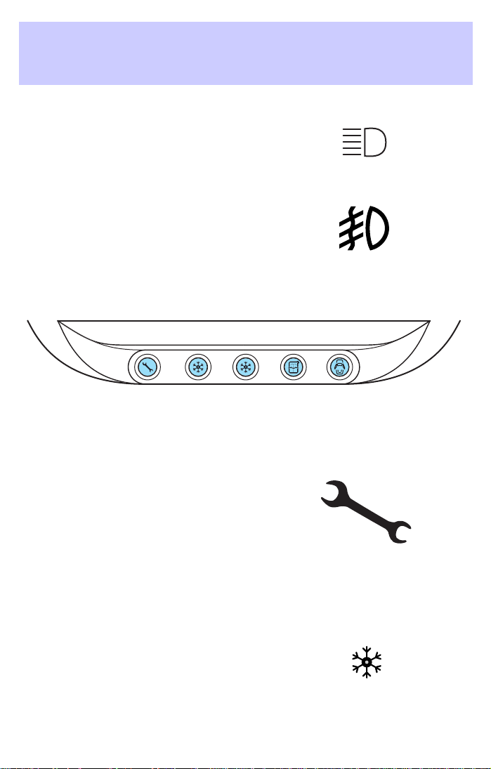
High beams
Illuminates when the high beam
headlamps are turned on.
Foglamps
Illuminates when the foglamps are
turned on.
Refer to Foglamp control in the
Lights chapter.
OVERHEAD WARNING LIGHTS (if equipped)
These lights illuminate briefly to ensure the systems are functional.
Service intervals
Illuminates to indicate that routine
service should be performed. Check
your maintenance schedule to
determine the routine service to be
completed.
To reset the light, hold the SELECT
and UNITS controls on the trip
computer for five seconds. The light
will be illuminated and then extinguish after approximately four seconds.
Frost warning
Illuminates when ambient air
temperatures are between 0° C (32°
F) and 4° C (39° F). The yellow
light warns of possible ice on the
roads.
14
Page 15
Instrument Cluster
Danger of ice warning
Illuminates when ambient air
temperature is 0° C (32° F) and
below. The red light warns of an
increased danger of icy roads.
The absence of a light in cold
temperatures does not necessarily mean that there is no risk of ice on
the road.
Low washer fluid
Illuminates when the windshield
washer fluid is low.
Door ajar
Illuminates when any door or
liftgate is open.
Safety belt warning chime
Sounds to remind you to fasten your safety belts.
BeltMinderY chime
Sounds intermittently to remind you to fasten your safety belts.
Supplemental restraint system (SRS) warning chime
Sounds when a malfunction in the supplemental restraint system (front
or side airbags) has been detected. Have the supplemental restraint
system inspected immediately.
Headlamps on warning chime
Sounds when the headlamps or parking lamps are on, the key is removed
from the ignition and the driver’s door is opened.
15
Page 16
Instrument Cluster
Key-in-ignition warning chime
Sounds when the key is left in the ignition and the driver’s door is
opened.
Liftgate ajar warning chime (if equipped)
Sounds when the liftgate is ajar or open and the key is in the ignition.
The interior dome lamp will also be illuminated.
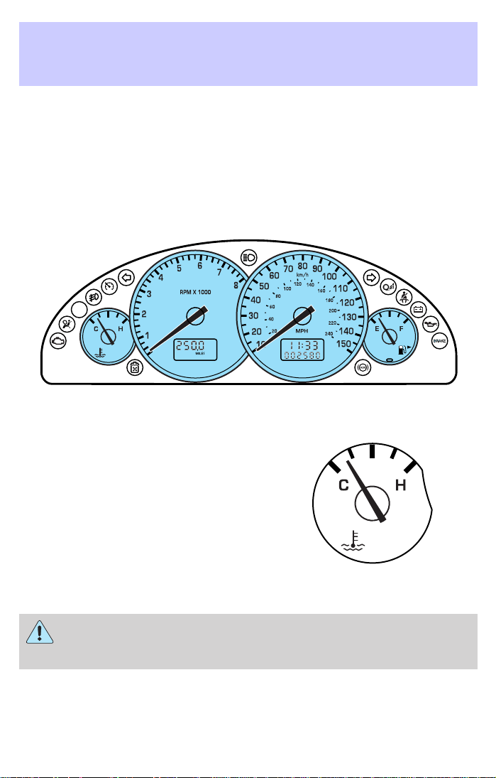
GAUGES
Engine coolant temperature gauge
Indicates the temperature of the
engine coolant. At normal operating
temperature, the needle remains
within the normal area (the area
between the “H” and “C”); if the
needle goes above the normal range,
the engine is overheating. Stop the
vehicle as soon as safely possible,
switch off the engine immediately
and let the engine cool. Refer to
Engine coolant in the
Maintenance and specifications chapter.
Never remove the coolant reservoir cap while the engine is
running or hot. Steam and scalding liquid from a hot cooling
system can burn you badly.
This gauge indicates the temperature of the engine coolant, not the
coolant level. If the coolant is not at its proper level the gauge indication
will not be accurate.
16
Page 17
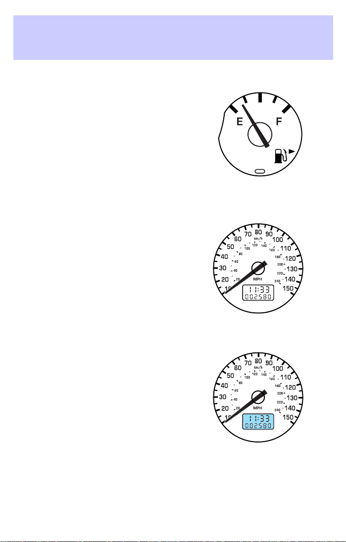
Fuel gauge
Displays approximately how much
fuel is in the fuel tank. The fuel
gauge may vary slightly when the
vehicle is in motion or on a grade.
When refueling the vehicle from an
empty indication, the amount of fuel
that can be added will be less than
the advertised capacity due to the
reserve fuel.
Speedometer
Indicates the current vehicle speed.
Odometer
Registers the total kilometers
(miles) of the vehicle.
Instrument Cluster
17
Page 18
Instrument Cluster
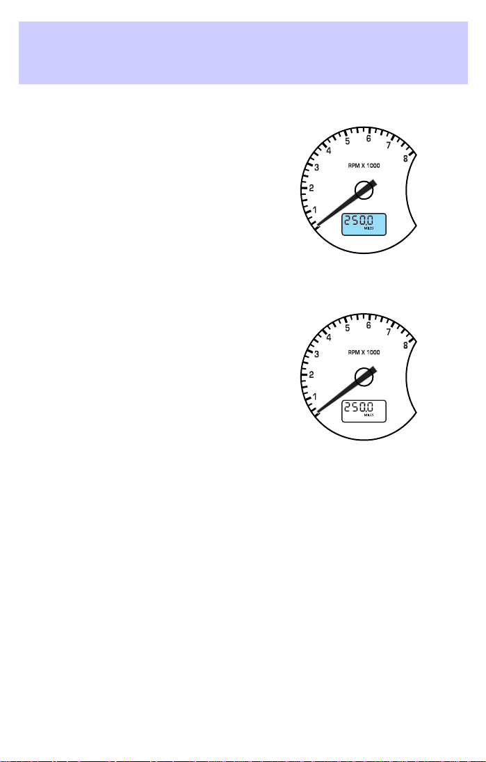
Trip odometer
Registers the kilometers (miles) of
individual journeys. To reset,
depress the SELECT control on the
trip computer.
Tachometer
Indicates the engine speed in
revolutions per minute.
Driving with your tachometer
pointer continuously at the top of
the scale may damage the engine.
18
Page 19
Entertainment Systems
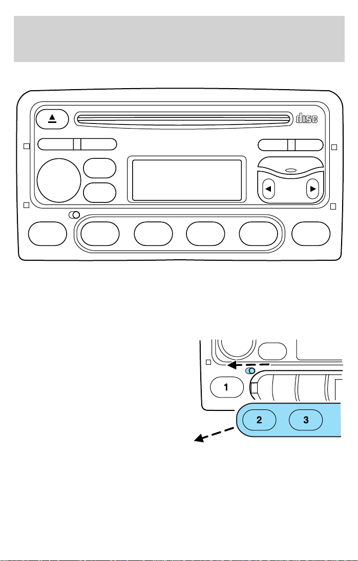
PREMIUM AM/FM STEREO/CD SYSTEM
BASS/TREB
VOL ON/OFF
FADE/BAL
SCAN
CLK
CD
AM/FM
MENU
SEEK
123456
Anti-theft protection panel
To deter would-be thieves, Ford audio units have a removable front panel
without which the unit will not work.
Avoid touching the contacts on the back of the panel and do not use
excessive force to refit it.
Slide the security release button to
the left and remove the front panel.
To reposition the panel, insert the
right-hand edge first, then the
left-hand side, until the retaining
latch is engaged.
Replacement panels
Your Ford dealer will require the following if you need to order a
replacement panel:
1. Your name and address.
2. The vehicle identification number (visible on a plate mounted on the
instrument panel.) Refer to Identifying your Vehicle.
19
Page 20
Entertainment Systems
3. The audio unit type.
4. Proof of identification (driver’s license, identity card, etc.).
5. A vehicle invoice (if the audio unit was installed in the vehicle prior to
delivery) or a parts invoice if the audio unit was purchased separately
form the vehicle, or an appropriate vehicle registration document.
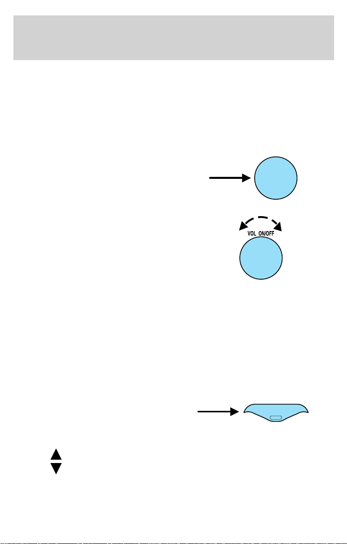
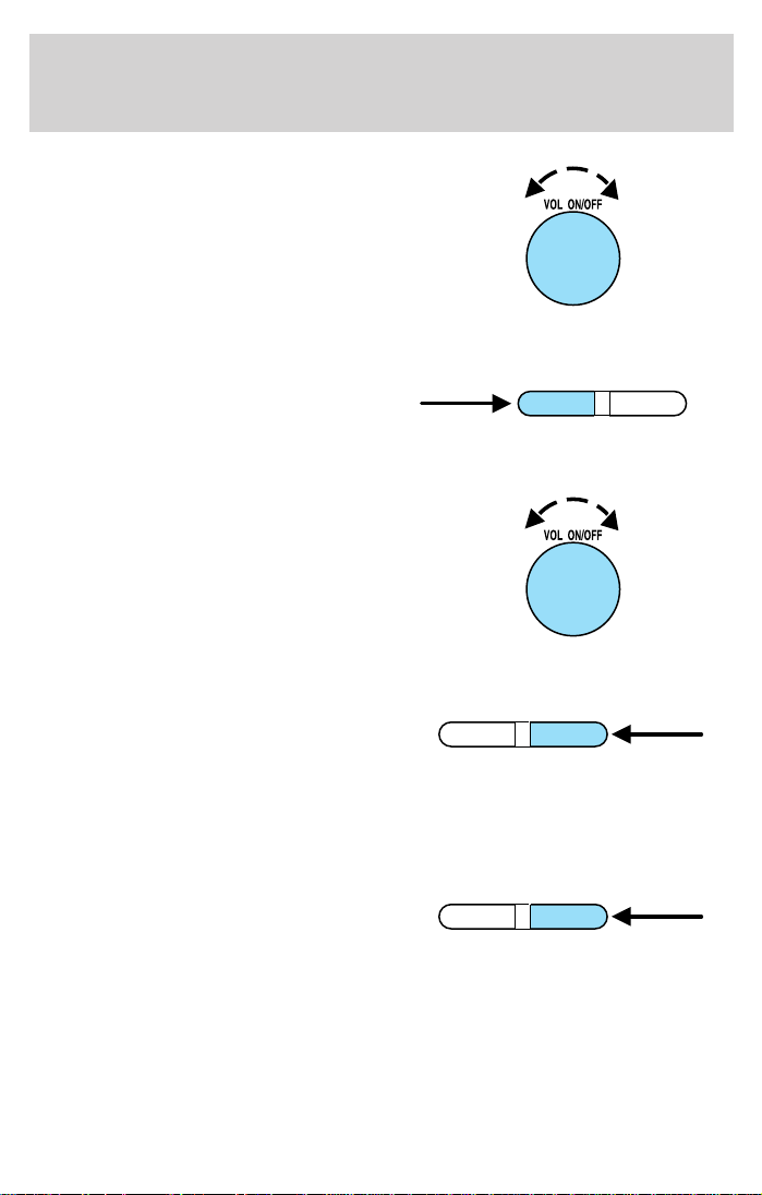
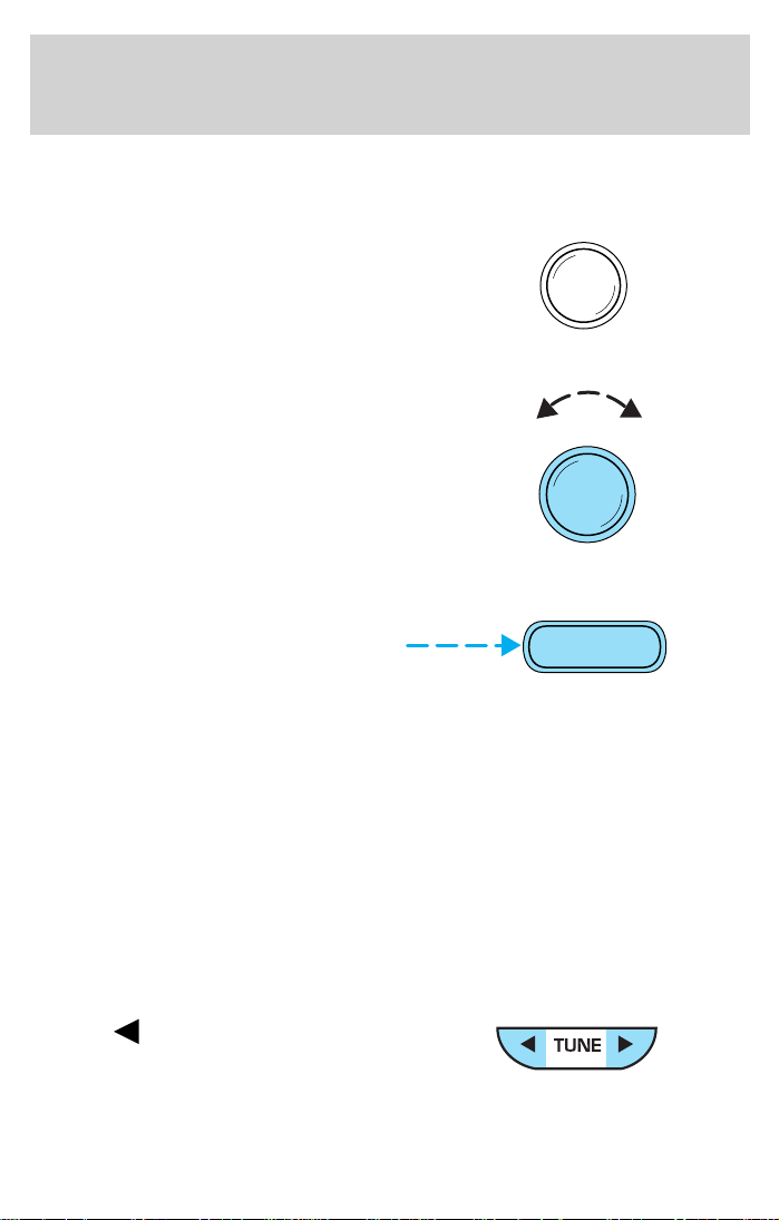
Volume/power control
Press the control to turn the audio
system on or off.
Turn the control to raise or lower
volume.
If the volume is set above a mid level and the ignition is turned off, the
volume will come back on at a “nominal” listening level when the ignition
switch is turned back on.
Automatic volume control (AVC) (if equipped)
With this feature, radio volume changes automatically with vehicle speed
to compensate for road and wind noise.
The recommended level for speed sensitive volume is from level 1
through level 3. Level 0 turns the speed sensitive volume off and level 7
is the maximum setting.
1. Press the MENU control twice.
AVC will appear in the display.
2. Use the SEEK control to adjust
the volume.
3. Press
4. Press
on the SEEK control to increase volume compensation
on the SEEK control to decrease or shut off the volume
compensation
This feature is not available on some vehicles and will not appear
as a menu function.
VOL ON/OFF
MENU
20
Page 21
Entertainment Systems
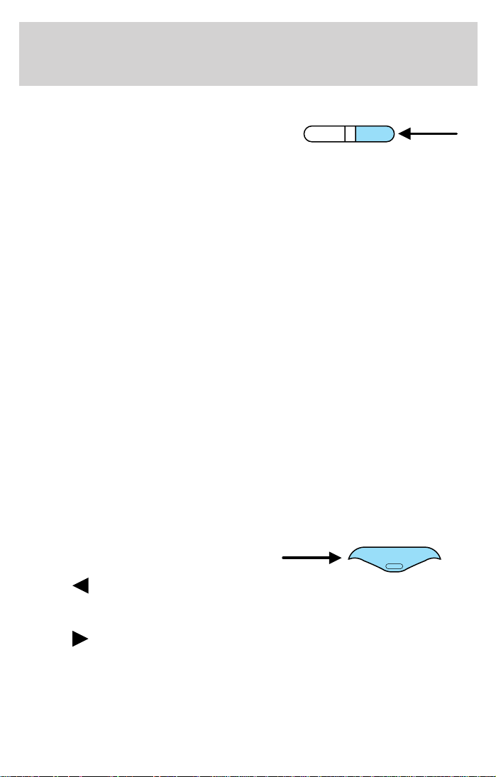
AM/FM select
The AM/FM select control works in
radio and CD modes.
To gain the best reception, always
tune to the strongest station signal available.
Under most conditions, the AM frequency provides stable sound quality
and little signal disturbance. However, at night, atmospheric conditions
may sometimes lead to interference from other stations.
The FM frequency offers higher quality sound broadcasts, but signal
strength can be subject to interference caused by:
• Limited range of some transmitters.
• Reception distortion as signals reflect off local buildings and other
objects.
• Signal “dead spots” where reception is obstructed or restricted.
AM/FM select in radio mode
This control allows you to select AM or FM frequency bands. Press the
control to switch between AM, FM1 or FM2 memory preset stations.
AM/FM select in CD mode
Press this control to stop CD play and begin radio play.
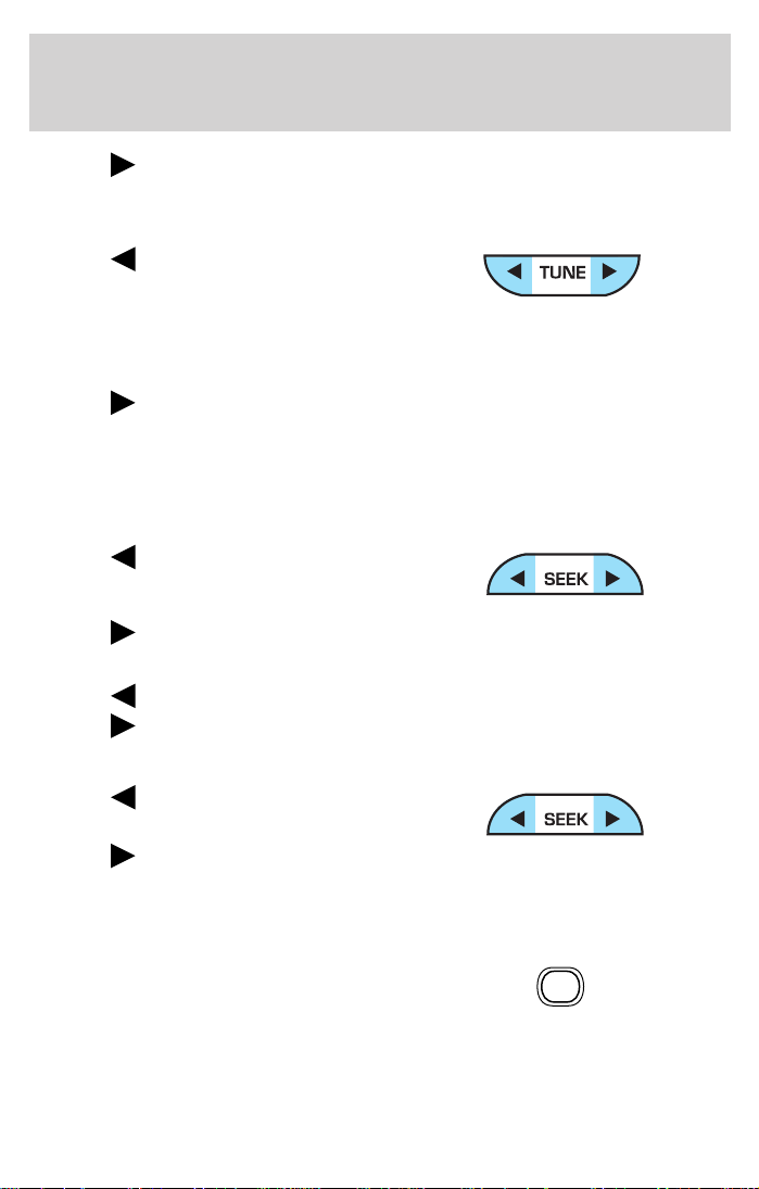
Tune adjust
The tune control works in radio mode and allows you to manually adjust
the frequency tuning.
Tune adjust in radio mode
• Press the MENU control until
MAN appears in the display.
• Press
on the SEEK control to
move down the band (whether or not a listenable station is located
there). Hold the control to move through the frequencies quickly.
• Press
on the SEEK control to move up the frequency up the band
(whether or not a listenable station is located there). Hold for quick
movement.
CD
AM/FM
MENU
21
Page 22
Entertainment Systems
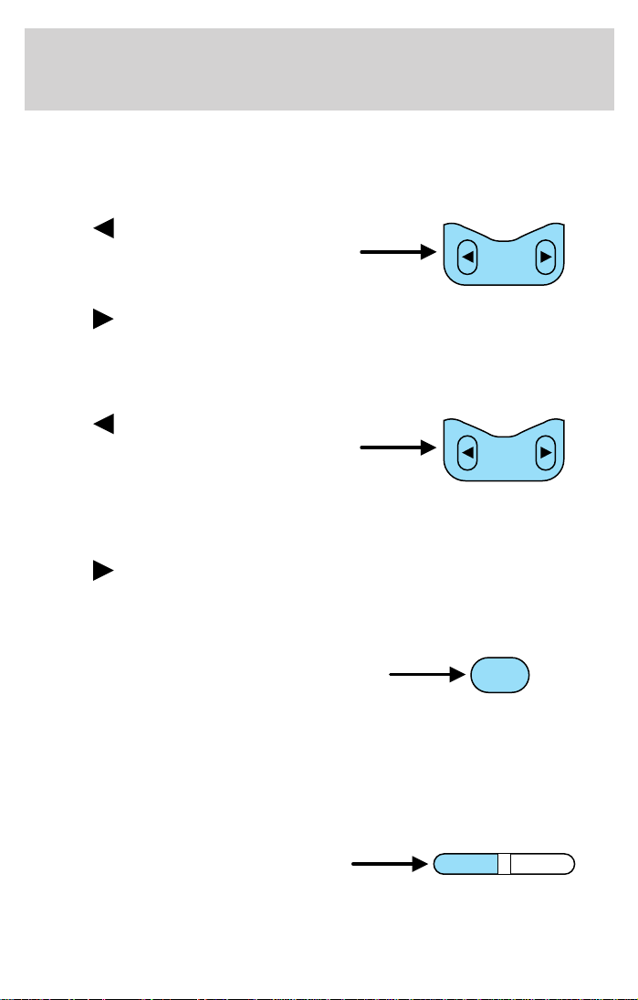
Seek function
The seek function works in radio and CD modes.
Seek function in radio mode
• Press to find the next
listenable station down the
frequency band. SEEK DOWN
will display.
SEEK
• Press
to find the next listenable station up the frequency band.
SEEK UP will display.
Seek function in CD mode (fast forward and reverse track
selection)
• Press to return to the
beginning of the current track. If
pressed within three seconds of
SEEK
the beginning of the track, the
previous track will be selected. Press repeatedly to select previous
tracks. Press and hold to search backwards across the tracks on the
disc.
• Press
to select the next track or press repeatedly to access later
tracks. Press and hold to search forward across the tracks on the disc.
Scan function
The scan function works in radio
mode.
SCAN
Scan function in radio mode
Press the SCAN control to hear a brief sampling of all listenable stations
on the frequency band. Press the SCAN control again to stop the scan
mode.
Treble adjust
The treble adjust control allows you
to increase or decrease the audio
BASS/TREB
FADE/BAL
system’s treble output.
Press the BASS/ TREB until TREB appears in the display.
22
Page 23
Entertainment Systems
Turn the volume control (VOL) up
or down to the desired setting.
Bass adjust
The bass adjust control allows you
to increase or decrease the audio
BASS/TREB
system’s bass output.
Press the BASS/ TREB control until BASS appears in the display.
Turn the volume control (VOL) up
or down to the desired setting.
Speaker fade adjust (if equipped)
Speaker sound can be adjusted
between the front and rear
BASS/TREB
FADE/BAL
speakers.
Press the FADE/BAL until FADE appears in the display.
Turn the volume (VOL) control to adjust the sound from the front
speakers to the rear speakers.
Speaker balance adjust
Speaker sound distribution can be
adjusted between the right and left
BASS/TREB
FADE/BAL
speakers.
Press the FADE/BAL until BAL appears in the display.
Turn the volume (VOL) control to adjust the sound between the right
and left speakers.
Stereo indicator (ST)
The stereo indicator (ST) appears in the display whenever a stereo
signal is received.
FADE/BAL
23
Page 24
Entertainment Systems
Radio station memory preset
The radio is equipped with six station memory preset controls. These
controls can be used to select up to six preset AM stations, twelve FM
stations (six in FM1 and six in FM2) and six on the remaining AutoStore
band.
Setting memory preset stations
1. Select the frequency band with the AM/FM select control.
2. Select a station. Refer to Tune adjust or Seek function for more
information on selecting a station.
3. Press and hold a memory preset control until the sound returns,
indicating the station is held in memory on the control you selected.
AutoStore selector
AutoStore allows you to set strong radio stations on the FM band
without losing your original manually set preset stations. This feature is
helpful on trips when you travel between cities with different radio
stations.
Starting AutoStore memory preset
1. Press and hold the AM/FM
control to activate AutoStore. AST
will flash in the display while the
system is searching for the strongest stations.
2. When the first six strong stations are filled, the station stored in
memory preset control 1 will start playing.
If there are less than six strong stations available on the frequency band,
the remaining memory preset controls will all store the last strong
station available.
CD
AM/FM
CD select
CD mode may be entered by
pressing the CD control. The first
track of the disc will begin playing.
After that, CD play will begin where it stopped last.
CD playback
CD playback starts and radio
reception is interrupted, when a CD
is inserted into the entry slot. PLAY
CD appears in the display.
24
CD
CD
AM/FM
AM/FM
Page 25
Entertainment Systems
Press CD to start playback from a CD already in the audio unit. If no
disc is inserted, NO CD appears in the display.
The display indicates elapsed track time up to 19:59. If the track is
longer than twenty minutes, the first digit flashes while the rest of the
numeral returns to zero and starts counting again.
This audio unit is designed to play commercially pressed 12cm
audio compact discs only. Due to technical incompatibility, certain
recordable and re-recordable compact discs may not function
correctly when used in CD players. Irregular shaped CDs, CDs
with a scratch protection film attached and CDs with homemade
paper (adhesive) labels should not be inserted into the CD player.
The label may peel and cause the CD to become jammed. It is
recommended that homemade CDs identified with a permanent
marker rather than adhesive labels. Please contact your dealer
for further information.
Shuffle feature
The shuffle feature operates in CD mode and plays all tracks on the
current disc in random order.
Press the MENU control until SHUF
appears in the display.
Press the SEEK control to turn the
feature ON (SHUF-ON) or OFF
(SHUF-OFF).
MENU
SEEK
When engaged, the elapsed time indicator in the display is replaced by
SHUF as a new track is selected.
If equipped with an optional CD changer, the audio unit plays all tracks
on the disc selected and then moves onto the next disc and plays those
tracks in a random sequence.
Compression feature
The compression feature brings soft and loud CD passages together for a
more consistent listening level.
Press the MENU control until COMP
appears in the display.
MENU
25
Page 26
Entertainment Systems
Press the SEEK control to turn the
feature ON or OFF.
Menu mode
Press the MENU control to access
main menu features.
Use the SEEK control for
adjustments.
CD eject function
Press the eject control during CD
playback to eject the CD.
Setting the clock
Your vehicle is equipped with a separate instrument panel mounted
clock. Please refer to Clock in the Driver controls chapter for
instructions on setting the clock.
PREMIUM AM/FM STEREO/CASSETTE/SINGLE CD
SEEK
MENU
26
VOL PUSH ON
AM FM
SEEK
TUNE
REW FF
FM 1
AMC
BL RF
DOLBY B NR
SCAN
BASS TREB SEL BAL
SIDE 1-2 COMP SHUFFLE
DISC
ST
TAPE
EJ CD
FADE
EJ
MUTE
AUTO
CLK
123456
Page 27
Entertainment Systems
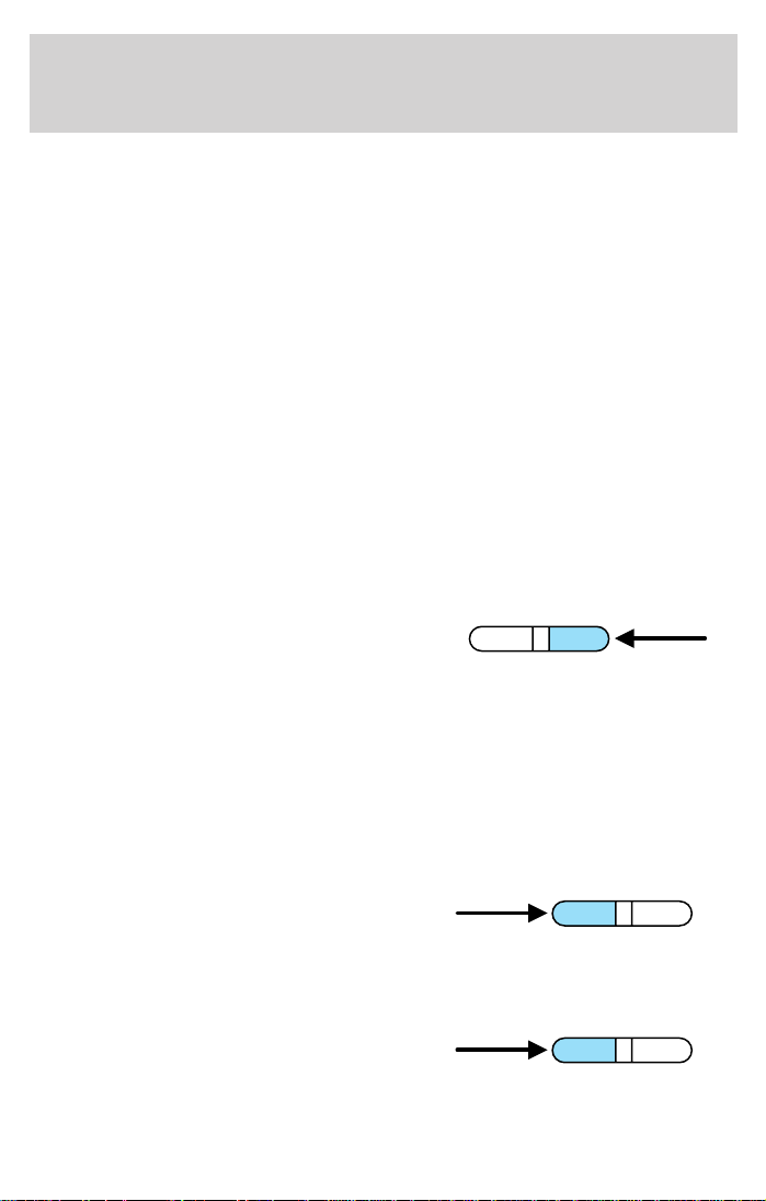
Volume/power control
Press the control to turn the audio
system on or off.
Audio power can also be turned on
by pressing the AM/FM select
control or the TAPE/CD select
control.
Turn control to raise or lower
volume.
AM/FM select
The AM/FM select control works in
radio, tape and CD modes.
AM/FM select in radio mode
This control allows you to select AM or FM frequency bands. Press the
control to switch between AM, FM1 or FM2 memory preset stations.
AM/FM select in tape mode
Press this control to stop tape play and begin radio play.
AM/FM select in CD or CD changer mode (if equipped)
Press this control to stop CD play and begin radio play.
VOL - PUSH ON
VOL - PUSH ON
AM FM
Tune adjust
The tune control works in radio or CD changer mode.
Tune adjust in radio mode
• Press to move to the next
frequency down the band
(whether or not a listenable
station is located there). Hold the control to move through the
frequencies quickly.
27
Page 28
Entertainment Systems
• Press to move to the next frequency up the band (whether or not
a listenable station is located there). Hold for quick movement.
Tune adjust for CD changer (if equipped)
• Press to select the previous
disc in the CD changer. (Play will
begin on the first track of the
disc unless the CD changer is in shuffle mode. Refer to Shuffle
feature for more information. Hold the control to continue reversing
through the remaining discs.
• Press
to fast-forward through the remaining discs.
Seek function
The seek function control works in radio, tape or CD mode.
Seek function in radio mode
• Press to find the next
listenable station down the
frequency band.
• Press
Seek function in tape mode
• Press to listen to the previous selection on the tape.
• Press
to select the next disc in the CD changer. Hold the control
to find the next listenable station up the frequency band.
to listen to the next selection on the tape.
Seek function in CD mode
• Press to seek to the previous
track of the disc.
• Press
next track of the current disc. After the last track has been
completed, the first track of the current disc will automatically replay.
Scan function
The scan function works in radio,
tape or CD mode.
to seek forward to the
SCAN
Scan function in radio mode
Press the SCAN control to hear a brief sampling of all listenable stations
on the frequency band. Press the control again to stop the scan mode.
28
Page 29
Entertainment Systems
Scan function in tape mode
Press the SCAN control to hear a short sampling of all selections on the
tape. (The tape scans in a forward direction. At the end of the tape’s
first side, direction automatically reverses to the opposite side of the
tape.) To stop on a particular selection, press the control again.
Scan function in CD or CD changer mode (if equipped)
Press the SCAN control to hear a short sampling of all selections on the
CD. (The CD scans in a forward direction, wrapping back to the first
track at the end of the CD.) To stop on a particular selection, press the
control again.
Radio station memory preset
The radio is equipped with six station memory preset controls. These
controls can be used to select up to six preset AM stations and twelve
FM stations (six in FM1 and six in FM2).
Setting memory preset stations
1. Select the frequency band with
the AM/FM select control.
2. Select a station. Refer to Tune
adjust or Seek function for more information on selecting a station.
3. Press and hold a memory preset control until the sound returns,
indicating the station is held in memory of the control you selected.
AM FM
Autoset memory preset
Autoset allows you to set strong radio stations without losing your
original manually set preset stations. This feature is helpful on trips
when you travel between cities with different radio stations.
29
Page 30
Entertainment Systems
Starting autoset memory preset
1. Select a frequency using the AM/FM select controls.
2. Press the control.
3. When the first six strong stations
are filled, the station stored in
memory preset control 1 will start
playing.
If there are less than six strong
stations available on the frequency
band, the remaining memory preset
controls will all store the last strong station available.
These stations are temporarily stored in the memory preset controls
(until deactivated) and are accessed in the same manner as your original
presets.
To deactivate autoset and return to your audio system’s manually set
memory stations, press the AUTO control again.
Bass adjust
The bass adjust control allows you
to increase or decrease the audio
system’s bass output.
Press the BASS control then press:
•
•
to decrease the bass output
and
to increase the bass output.
AUTO
CLK
BASS TREB
Treble adjust
The treble adjust control allows you
to increase or decrease the audio
system’s treble output.
Press the TREB control then press:
•
•
30
to decrease the treble output
and
to increase the treble output.
BASS TREB
Page 31

Entertainment Systems
Speaker balance adjust
Speaker sound distribution can be
adjusted between the right and left
speakers.
Press the BAL control then press:
•
•
Speaker fade adjust
Speaker sound can be adjusted
between the front and rear
speakers.
Press the FADE control then press:
• to shift the sound to the
•
Tape/CD select
• To begin tape play (with a tape
• To begin CD play (if CD(s) are
Press the CD control to toggle between single CD and CD changer play
(if equipped).
CD units are designed to play commercially pressed 12 cm (4.75
in) audio compact discs only. Due to technical incompatibility,
certain recordable and re-recordable compact discs may not
function correctly when used in Ford CD players. Irregular
shaped CDs, CDs with a scratch protection film attached, and CDs
with homemade paper (adhesive) labels should not be inserted
to shift sound to the left and
to shift sound to the right.
front and
to shift the sound to the rear.
loaded into the audio system)
while in the radio or CD mode,
press the TAPE control. Press
again during rewind or fast forward to stop the rewind or fast forward
function.
loaded), press the CD control.
The first track of the disc will
begin playing. If returning from
radio or tape mode, CD play will begin where it stopped last.
BAL FADE
BAL FADE
TAPE CD
TAPE CD
31
Page 32

Entertainment Systems
into the CD player. The label may peel and cause the CD to
become jammed. It is recommended that homemade CDs be
identified with permanent felt tip marker rather than adhesive
labels. Ball point pens may damage CDs. Please contact your
dealer for further information.
Rewind
The rewind control works in tape
and CD modes.
• In tape mode, radio play will
continue until rewind is stopped
(with the TAPE control) or the beginning of the tape is reached.
• In CD mode, pressing the REW control rewinds the CD within the
current track.
Fast forward
The fast forward control works in
tape and CD modes.
• In the tape mode, tape direction
will automatically reverse when
the end of the tape is reached.
• In CD mode, pressing the FF control fast forwards the CD within the
current track.
REW
1
FF
2
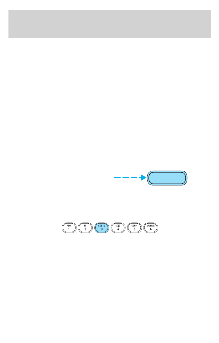
Tape direction select
Press to play the alternate side of
the tape.
Eject function
Press the EJ control to stop and
eject a tape.
Press the EJ control to stop and
eject a CD.
32
SIDE 1-2
3
EJ
EJ
Page 33

Entertainment Systems
DolbyT noise reduction
Dolbyt noise reduction operates in
tape mode. Dolbyt noise reduction
reduces the amount of hiss and
static during tape playback.
Press the
reduction.
Dolbyt noise reduction is manufactured under license from Dolbyt
Laboratories Licensing Corporation. “Dolbyt” and the double-D
symbol
Corporation.
Compression adjust
Compression adjust brings soft and
loud CD passages together for a
more consistent listening level.
Press the COMP control to activate
and deactivate compression adjust.
Shuffle feature
The shuffle feature operates in CD
mode and plays all tracks on the
current disc in random order. If
equipped with the CD changer, the
shuffle feature continues to the next
disc after all tracks on the current disc are played.
Press to start this feature. Random order play will continue until the
control is pressed again.
control to activate (and deactivate) the Dolbyt noise
are registered trademarks of Dolbyt Laboratories Licensing
4
COMP
5
SHUFFLE
6
Setting the clock
Your vehicle is equipped with a separate instrument panel mounted
clock. Please refer to Clock in the Driver controls chapter for
instructions on setting the clock.
33
Page 34

Entertainment Systems
Mute mode
Press the MUTE control to mute the
playing media. Press the MUTE
control again to return to the
playing media.
PREMIUM AM/FM STEREO IN DASH SIX CD RADIO
EJ
MUTE
SHUF COMP
SCAN
LOAD
PUSH ON
AM
CD
FM
DISC
TUNE
SEEK REW FF
1 2 3 4 5 6
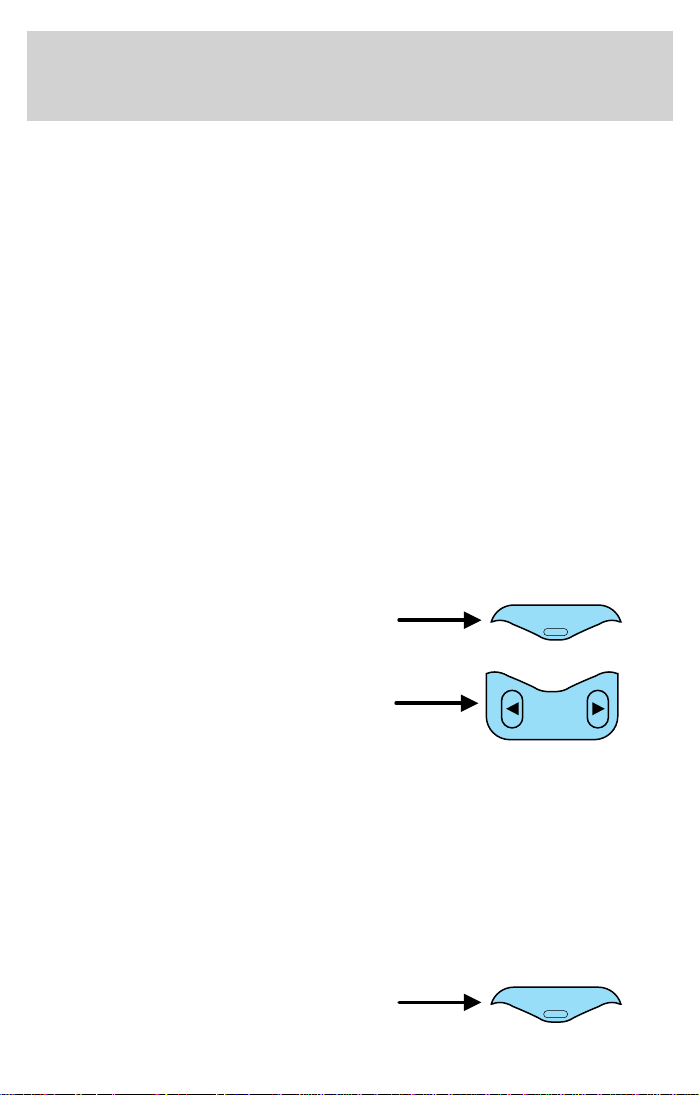
Volume/power control
Press the control to turn the audio
system on or off. Turn the control to
raise or lower volume.
PUSH ON
AM/FM select
The AM/FM select control works in
radio and CD modes.
AM
FM
MUTE
EJ
BALBASS
SEL
FADETREB
MENU
CD
34
Page 35

Entertainment Systems
AM/FM select in radio mode
This control allows you to select AM or FM frequency bands. Press the
control to switch between AM, FM1 or FM2 memory preset stations.
AM/FM select in CD mode
Press this control to stop CD play and begin radio play.
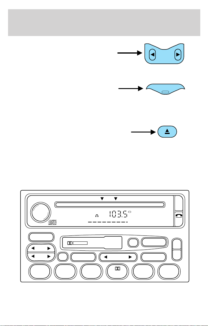
Tune/disc adjust
The tune control works in radio or CD mode.
Tune adjust in radio mode
• Press to move to the next
frequency down the band
(whether or not a listenable
station is located there). Hold the control to move through the
frequencies quickly.
• Press
to move to the next frequency up the band (whether or not
a listenable station is located there). Hold for quick movement.
Disc adjust for CD mode
• Press to select the previous
disc. (Play will begin on the first
track of the disc unless shuffle
mode is engaged.) Refer to Shuffle feature for more information. Hold
the control to continue reversing through the discs.
• Press
to select the next disc. Hold the control to fast-forward
through the remaining discs.
DISC
TUNE
DISC
TUNE
Seek function
The seek function works in radio or CD mode.
Seek function in radio mode
• Press to find the next
listenable station down the
frequency band. SEEK DOWN
will display.
• Press
to find the next listenable station up the frequency band.
SEEK UP will display.
35
Page 36

Entertainment Systems
Seek function in CD mode
• Press to seek to the previous
track of the current disc. If the
beginning of the disc is reached,
the CD player seeks to the
beginning of the last track on the current disc and begins playing.
• Press
the last track has been completed, the first track of the current disc
will automatically replay.
Scan function
The scan function works in radio or
CD mode.
Scan function in radio mode
Press the SCAN control to hear a brief sampling of all listenable stations
on the frequency band. Press the SCAN control again to stop the scan
mode.
Scan function in CD mode
Press the SCAN control to hear a short sampling of all selections on the
CD. (The CD scans in a forward direction, wrapping back to the first
track at the end of the CD.) To stop on a particular selection, press the
control again.
to seek forward to the next track of the current disc. After
Radio station memory preset
The radio is equipped with six station memory preset controls. These
controls can be used to select up to six preset AM stations and twelve
FM stations (six in FM1 and six in FM2).
Setting memory preset stations
1. Select the frequency band with the AM/FM select control. Press the
AM/FM control to toggle between AM, FM1, or FM2.
2. Press the SEEK control to access the next listenable station up or
down the frequency band. Press the TUNE control to go up or down the
listening band in individual increments.
3. Select a station. Refer to Seek function for more information on
selecting a station.
4. Press and hold a memory preset control. The playing media will mute
momentarily. When the sound returns, the station is held in memory on
36
Page 37

Entertainment Systems
the control you selected. The display will read SAVED.
Autostore
Autostore allows you to set the strongest local radio stations without
losing your original manually set preset stations. This feature is helpful
on trips when you travel between cities with different radio stations.
Starting autostore
1. Press and momentarily hold the AM/FM control.
2. AUTOSET will flash in the display
as the frequency band is scrolled
through.
3. When the six strongest stations are filled, the station stored in
memory preset control 1 will start playing.
If there are fewer than six strong stations available on the frequency
band, the remaining memory preset controls will all store the last strong
station available.
To deactivate autoset and return to your audio system’s manually set
memory stations, press the AM/FM control again.
AM
FM
CD
CD select
CD mode may be entered by
pressing the CD control and the
AM
FM
CD
LOAD control. Load the CD into the
audio system. The first track of the
disc will begin playing. After that, CD play will begin where it stopped
last.
If an alternative CD is desired, press the corresponding preset control
(1–6) of a loaded CD, or press the TUNE control to access the other
loaded CDs.
NO CD will display if the CD control is activated when there is not a CD
present in the audio system.
If the CD control is pressed followed by with a preset number and that
particular slot is empty, NO CD will display and the system will begin to
play the next available disc.
37
Page 38

Entertainment Systems
CD units are designed to play commercially pressed 12 cm (4.75
in) audio compact discs only. Due to technical incompatibility,
certain recordable and re-recordable compact discs may not
function correctly when used in Ford CD players. Irregular
shaped CDs, CDs with a scratch protection film attached, and CDs
with homemade paper (adhesive) labels should not be inserted
into the CD player. The label may peel and cause the CD to
become jammed. It is recommended that homemade CDs be
identified with permanent felt tip marker rather than adhesive
labels. Ball point pens may damage CDs. Please contact your
dealer for further information.
Display description
Six circles are always lit in the digital display. These signify the six CD
slots in the audio system. When a disc is loaded into a particular slot
(1–6), the number inside that specific circle lights. If the circle is empty,
there is no CD in that particular slot.
Load
The load feature allows you to load
single CDs into the player internal
to the radio.
This six disc CD player is equipped with a CD door. Compact
discs should only be inserted into the player after the door has
been opened by the player. Do not attempt to force the door
open. Compact discs should only be loaded by pressing the LOAD
control.
Press the LOAD control. (You can choose which slot will be loaded by
pressing the desired preset number. If you do not choose a slot, the
system will choose the next available one.) Wait until the CD door opens.
Load the CD into the player. LOADING CD# is displayed. When the CD
has been loaded, the door will close and the CD will begin to play. For
example, to load a CD into slot 2, press the LOAD control and then press
preset 2.
Auto load
This feature allows you to autoload
up to 6 discs into the multi disc CD
player internal to the radio.
Press and hold the LOAD control until AUTOLOAD # is displayed. The
CD door will open. Load the desired discs, one at a time. The CD is
LOAD
LOAD
38
Page 39

Entertainment Systems
loaded into position and the audio system will display CD#. Each time
the CD door opens, INSERT CD# is displayed. The door will close and
the player will move to the next slot after each disc has been loaded.
The process is repeated until all 6 slots are full. The audio system plays
the last CD loaded and the display is updated. If some slots are already
full and autoload is activated, the system will fill all empty slots.
Eject
Press the EJ control to stop and
eject a CD. You can choose which
CD will be ejected by pressing the
EJ control and the desired preset number (1–6). For example, to eject
CD 2, press the EJ control and then press the preset 2 control. If you do
not choose a specific CD, the player will eject the current CD.
If a CD is ejected and not removed from the door of the CD player, the
player will automatically reload the CD. This feature may be used when
the ignition is ON or OFF.
Auto eject
Press and momentarily hold the EJ
control to engage auto eject. All CDs
which are present in the player will
be ejected one at a time. If a CD is ejected and not removed from the
door of the CD player, the player will automatically reload the CD. This
feature may be used when the ignition is ON or OFF.
EJ
EJ
Rewind
The rewind control works in CD
modes.
REW FF
Press and hold the REW control
until the desired selection is reached. If the beginning of the disc is
reached, the CD will begin play at the first track. Release the control to
disengage rewind mode.
When in rewind mode, your audio system will automatically lower the
volume level of the playing media.
Fast forward
The fast forward control works in
CD modes.
REW FF
39
Page 40

Entertainment Systems
Press and hold the FF control until the desired selection is reached. If
the end of the disc is reached, the CD will return to the first track.
Release the control to disengage fast forward mode.
When in fast forward mode, your audio system will automatically lower
the volume level of the playing media.
Shuffle feature
Press the SHUF control until the
desired shuffle mode is displayed.
The audio system will then engage
the desired shuffle mode.
When engaged, the shuffle feature has two different modes: SHUFFLE
DISC and SHUFFLE TRK.
SHUFFLE DISC randomly plays tracks from all the discs presently in the
audio system.
SHUFFLE TRK plays all the tracks on the current disc in random order.
Compression feature
The compression feature operates in CD mode and brings soft and loud
CD passages together for a more consistent listening level.
Press the COMP control until COMP
ON is displayed.
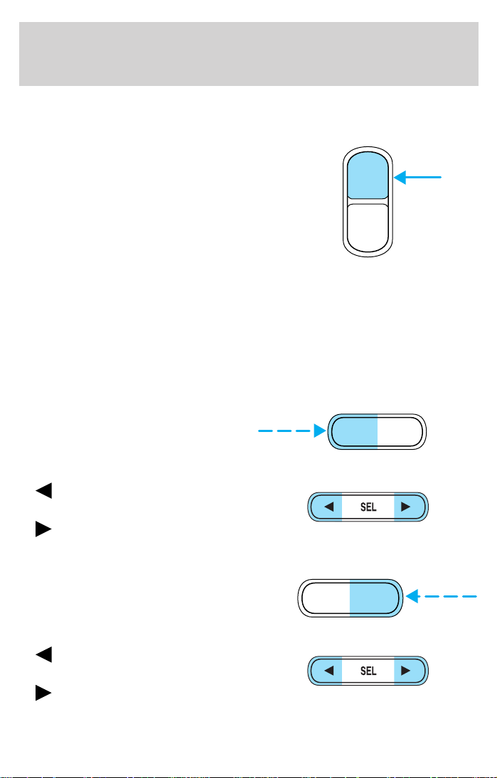
Bass adjust
The bass adjust control allows you
to increase or decrease the audio
system’s bass output.
Press the BASS control. Use the
SEL control to increase or decrease
the amount of bass.
Treble adjust
The treble adjust control allows you
to increase or decrease the audio
system’s treble output.
Press the TREB control. Use the
SEL control to increase or decrease
the amount of treble.
40
BASS
TREB
BASS
TREB
+
+
SEL
SEL
Page 41

Entertainment Systems
Speaker balance adjust
Speaker sound distribution can be
adjusted between the right and left
speakers.
Press the BAL control. Use the SEL
control to adjust the sound between
the left and right speakers.
Speaker fade adjust
Speaker sound can be adjusted
between the front and rear
speakers.
Press the FADE control. Use the
SEL control to adjust the sound
between the front and rear speakers.
Mute mode
Press the control to mute the
playing media. Press the control
again to return to the playing media.
Setting the clock
Your vehicle is equipped with a separate instrument panel mounted
clock. Please refer to Clock in the Driver controls chapter for
instructions on setting the clock.
BAL
FADE
BAL
FADE
+
+
SEL
SEL
TROUBLESHOOTING THE CD PLAYER (IF EQUIPPED)
If sound skips:
• You may be traveling on a rough road, playing badly scratched discs or
the disc may be dirty. Skipping will not scratch the discs or damage
the player.
If player does not work:
• The disc is inserted with the label surface downward.
• The disc is dusty or defective.
• A disc with format and dimensions not within industry standards is
inserted.
41
Page 42

Entertainment Systems
CD units are designed to play commercially pressed 12 cm (4.75
in) audio compact discs only. Due to technical incompatibility,
certain recordable and re-recordable compact discs may not
function correctly when used in Ford CD players. Irregular
shaped CDs, CDs with a scratch protection film attached, and CDs
with homemade paper (adhesive) labels should not be inserted
into the CD player. The label may peel and cause the CD to
become jammed. It is recommended that homemade CDs be
identified with permanent felt tip marker rather than adhesive
labels. Ball point pens may damage CDs. Please contact your
dealer for further information.
For best possible sound quality, use CDs that are clean and in
good condition.
CLEANING COMPACT DISCS
Inspect all discs for contamination before playing. If necessary, clean
discs only with an approved CD cleaner and wipe from the center out to
the edge. Do not use circular motion.
CLEANING CASSETTE PLAYER (IF EQUIPPED)
Clean the tape player head with a cassette cleaning cartridge after 10 to
12 hours of play in order to maintain the best sound and operation.
RADIO FREQUENCY INFORMATION
The Federal Communications Commission (FCC) and the Canadian Radio
and Telecommunications Commission(CRTC) establish the frequencies
AM and FM stations may use for their broadcasts. Allowable frequencies
are:
AM 530, 540–1600, 1610 kHz
FM 87.7, 87.9–107.7, 107.9 MHz
Not all frequencies are used in a given area.
42
Page 43

Entertainment Systems
RADIO RECEPTION FACTORS
Three factors can affect radio reception:
• Distance/strength. The further an FM signal travels, the weaker it is.
The listenable range of the average FM station is approximately 40 km
(24 miles). This range can be affected by “signal modulation.” Signal
modulation is a process radio stations use to increase their
strength/volume relative to other stations.
• Terrain. Hills, mountains and tall buildings between your vehicle’s
antenna and the radio station signal can cause FM reception problems.
Static can be caused on AM stations by power lines, electric fences,
traffic lights and thunderstorms. Moving away from an interfering
structure (out of its “shadow”) returns your reception to normal.
• Station overload. Weak signals are sometimes captured by stronger
signals when you pass a broadcast tower. A stronger signal may
temporarily overtake a weaker signal and play while the weak station
frequency is displayed.
The audio system automatically switches to single channel reception if it
will improve the reception of a station normally received in stereo.
AUDIO SYSTEM WARRANTIES AND SERVICE
Refer to the Warranty Guide for audio system warranty information.
If service is necessary, see your dealer or a qualified technician.
43
Page 44

Climate Controls
MANUAL HEATING AND AIR CONDITIONING SYSTEM
Fan speed control
Controls the volume of air circulated
in the vehicle.
Temperature control knob
Controls the temperature of the
airflow inside the vehicle.
Mode selector control
Controls the direction of the airflow
to the inside of the vehicle.
• MAX A/C – Distributes recirculated air through the instrument panel
registers. The A/C compressor will only function if the outside
temperature is above approximately 6°C (43°F). MAX A/C is noisier
than A/C, but more economical and efficient. This mode may prevent
undesirable odors from entering the vehicle.
• A/C – Distributes outside air through the instrument panel registers.
The A/C compressor will only function if the outside temperature is
above approximately 6°C (43°F) .
•
44
(Panel) – Distributes outside air through the instrument panel
registers. The air can not be cooled below the outside temperature.
Page 45

Climate Controls
• O (Off) – Outside air is shut out and the fan will not operate. This
mode may reduce undesirable odors from entering the vehicle but may
increase the possibility of interior window fogging.
•
•
•
Since the air conditioner removes moisture from the air, it is
considered normal operation if water drips on the ground under
the air conditioner drain.
Operating tips
• To reduce fogging in humid weather, place the climate control system
• To reduce humidity buildup inside the vehicle under warm weather
• To reduce humidity buildup inside the vehicle under cold weather
• Under normal weather conditions, do not leave your vehicle in the
• Under snowy or dirty weather conditions, leave your vehicle in the
• Remove any snow, ice or leaves from the exterior base of the
• To increase the efficiency of the A/C (if equipped), drive with the
(Floor) – Distributes outside air through the floor ducts. The air
cannot be cooled below the outside temperature.
(Floor and defrost) – Distributes outside air through the
windshield defroster ducts and the floor duct and the side window
demisters. The A/C compressor will operate automatically if the
outside temperature is above approximately 6°C (43°F) . The air
distributed through the floor ducts will be slightly warmer than the air
sent to the windshield defrost ducts and the side window demisters.
(Defrost) – Distributes outside air through the windshield
defroster ducts and the side window demisters. The A/C compressor
will operate automatically if the outside temperature is above
approximately 6°C (43°F). This mode will clear ice and fog from the
windshield.
in Defrost and Rear Defrost mode (if equipped) before driving.
conditions, do not drive with the climate control system in the Off
mode.
conditions, do not drive with the climate control system in Max A/C (if
equipped), recirculation mode (if equipped) or Off mode.
Max A/C (if equipped), recirculation mode (if equipped) or Off mode
when turning off the vehicle.
Max A/C (if equipped), recirculation mode (if equipped) or Off mode
when turning off the ignition.
windshield.
windows slightly open for two to three minutes. or until the vehicle
has been “aired out”.
45
Page 46

Climate Controls
• Do not place objects under the front seat or over the defroster ducts.
They may reduce visibility, fall into the ducts, or degrade the
performance of your climate control system.
Do not place objects on top of the instrument panel, as these
objects may become projectiles in a collision or sudden stop.
REAR WINDOW DEFROSTER
The rear defroster control is located
on the instrument panel.
Press the rear defroster control to
clear the rear window of thin ice
and fog.
• A small LED will illuminate when
the rear defroster is activated.
The ignition must be in the ON position to operate the rear window
defroster.
The defroster turns off automatically after 10 minutes or when the
ignition is turned to the OFF position. To manually turn off the defroster
before 10 minutes have passed, push the control again.
CABIN AIR FILTER
Your vehicle is equipped with an air filter that removes pollen and road
dust from outside air before it is directed to the interior of the vehicle.
The particulate filtration system gives the following benefits to
customers:
• Improves the customer’s driving comfort by reducing particle
concentration
• Improves the interior compartment cleanliness
• Protects the climate control components from particle deposits
For more information, or to replace the filter, contact your local dealer.
46
Page 47

HEADLAMP CONTROL
Rotate the headlamp control to the
first position to turn on the parking
lamps.
Rotate to the second position to
turn on the headlamps.
Foglamp control (if equipped)
The headlamp control also operates
the foglamps. The foglamps can be
turned on when the headlamp
control is in the
the
beams are not turned on.
Pull headlamp control towards you
to turn foglamps on. The foglamp
indicator light
position and the high
or
will illuminate.
Lights
Daytime running lamps (DRL) (if equipped)
Turns the headlamps on with a reduced output.
To activate:
• the ignition must be in the ON position and
• the headlamp control is in the OFF or Parking lamps position.
Always remember to turn on your headlamps at dusk or during
inclement weather. The Daytime Running Lamp (DRL) system
does not activate with your tail lamps and generally may not provide
adequate lighting during these conditions. Failure to activate your
headlamps under these conditions may result in a collision.
47
Page 48

Lights
High beams
Push the lever toward the
instrument panel to activate. Pull
the lever towards you to deactivate.
Flash to pass
Pull toward you slightly to activate
and release to deactivate.
PANEL DIMMER CONTROL
Use to adjust the brightness of the
instrument panel during parklamp,
headlamp, and autolamp operation.
• Rotate up to brighten.
• Rotate down to dim.
• Rotate fully up to turn on the
interior lights.
48
Page 49

Lights
AIMING THE HEADLAMPS
The headlamps on your vehicle are properly aimed at the assembly plant.
If your vehicle has been aimed in an accident the alignment of your
headlamps should be checked by a qualified service technician.
Each headlmap may be properly aimed in the vertical (up/down)
direction only. THE HORIZONTAL (left/right) AIM IS PRESET BY THE
HEADLAMP MANUFACTURER AND DOES NOT NEED TO BE
RE-AIMED.
Adjusting the vertical aim
1. Park the vehicle on a level
surface.
2. The vertical indicator is located
on top of the headlamp assembly;
the adjusting screw is located
behind the headlamp assembly.
3. Turn the vertical adjusting screw
until the bubble aligns with the “0”
reference mark when viewed from
directly above. The “0” reference
mark is the middle of the three (3)
bold graduation marks.
49
Page 50

Lights
TURN SIGNAL CONTROL
• Push down to activate the left
turn signal.
• Push up to activate the right turn
signal.
• In vehicles equipped with daytime
running lights, use of the turn
signals will shut off the
highbeams in daytime driving.
INTERIOR LAMPS
The interior lamps have three
switch positions: door delay, off and
on.
When the control is switched to
door delay, the interior light stays
on for 12 seconds after the doors
are closed with the ignition off.
Reading lamps (if equipped)
The reading lamps are operated by
separate on/off switches and can be
adjusted to point in the desired
direction.
50
Page 51

Lights
BULBS
Replacing exterior bulbs
Check the operation of the following lamps frequently:
• Headlamps
• Tail lamps
• Brakelamps
• High-mount brakelamp
• Turn signal lamps
• Backup lamps
• License plate lamp
Do not remove lamp bulbs unless they will be replaced immediately. If a
bulb is removed for an extended period of time, contaminants may enter
the lamp housings and affect performance.
Using the right bulbs
Replacement bulbs are specified in the chart below. Headlamp bulbs
must be marked with an authorized “D.O.T.” for North America to assure
lamp performance, light brightness and pattern and safe visibility. The
correct bulbs will not damage the lamp assembly or void the lamp
assembly warranty and will provide quality bulb burn time.
Function Number of
bulbs
Front park/turn lamps 2 3157 NA
Headlamps (high) 2 9005
Headlamps (high) 2 9006
Foglamps 2 893
Rear tail/turn/brake lamp 2 1157
Backup lamp 2 1156
High-mount brakelamp 1 2825/W5W
License plate lamp 2 168
Signal mirror lamp (if equipped) 2 194
All replacement bulbs are clear in color except where noted.
To replace all instrument panel lights - see your dealer
Trade number
51
Page 52

Lights
Replacing headlamp bulbs
Make sure the headlamp switch is in the OFF position.
To remove the high or low beam headlamp bulb:
1. Lift the hood and release the wire
clip on the rear of the headlamp
assembly and remove the cover.
2. Disconnect the electrical
connector by turning the bulb
holder counterclockwise.
3. Pull the bulb holder straight out
to remove the bulb.
To install the new bulb:
Handle a halogen headlamp bulb carefully and keep out of
children’s reach. Grasp the bulb by only its plastic base and do
not touch the glass. The oil from your hand could cause the bulb to
break the next time the headlamps are operated.
Note: If the bulb is accidentally touched, it should be cleaned with
rubbing alcohol before being used.
1. Install the new bulb in the lamp assembly by pushing it straight in and
turning to lock it in position. You may need to turn the bulb slightly to
align the grooves in the plastic base with the tabs in the lamp assembly.
52
Page 53

Lights
2. Connect the electrical connector to the bulb.
3. Install the protective cover and secure it with the wire clips.
4. Turn the headlamps on and make sure they work properly. if the
headlamp was correctly aligned before you changed the bulb, you need
to align it again.
Replacing front parking lamp/turn signal bulbs
1. Remove the headlamp assembly
cover.
2. Turn the bulb holder counter
clockwise.
3. Remove the bulb socket by
pulling it straight out from the lamp
assembly.
4. Pull the bulb straight out of the
socket and press in the new bulb.
5. Install the bulb socket into the
lamp assembly by turning clockwise.
Replacing side marker lamps
1. Push the complete light assembly
to the front and pull it out.
2. Remove the socket from the
assembly by turning it counter
clockwise.
3. Pull the bulb straight out and
replace it.
4. Install the bulb socket into the
assembly by turning it clockwise.
Replacing brake/turn signal/tail/backup lamps
The brake, turn signal, tail and backup lamps bulbs are located in the
same portion of the tail lamp assembly. Follow the same steps to replace
either bulb.
53
Page 54

Lights
1. From the trunk, remove the
carpet cover from the lamp
assembly.
2. Remove the three retainer nuts
and pull the lamp assembly out.
3. Turn the bulb counterclockwise
and pull it out.
4. Replace the defective bulb.
5. Replace the lamp assembly and
turn it clockwise to secure it in
place.
Replacing the rear parking lamps
1. From the trunk, locate the
parking lamp on the trunk wall near
the tail lamp.
2. Turn the bulb socket
counterclockwise and pull it out.
3. Pull the bulb straight out and
replace it.
4. Add a bulb by pushing it straight
in to the bulb socket.
5. Replace the bulb socket and turn
it clockwise to secure it in place.
Replacing foglamp bulbs (if equipped)
For bulb replacement, see a dealer or qualified technician.
54
Page 55

Replacing high-mount brake
lamp bulbs
1. Remove the push pins and cover
from the liftgate. (To remove the
push pins, press the two tabs of the
push pin insert inward and pull the
insert out.)
2. Turn the bulb socket
counterclockwise.
3. Pull the bulb straight out of the
socket and push in the new bulb.
To install the lamp assembly:
1. Install the bulb into the lamp assembly and turn it clockwise
2. Replace the cover and the push pins.
Replacing the luggage compartment lamp
1. Remove the light assembly from
the underside of the liftgate.
2. Turn the spherical bulb (with
slight pressure) counterclockwise to
remove.
3. To replace the bulb, insert bulb
and turn it clockwise to secure in
place.
Lights
55
Page 56

Lights
Replacing interior lamps
1. Switch off the interior lamps
(middle switch position).
2. Open the lamp assembly.
3. Release the reflector at the side.
4. Pull out and replace the bulb.
Replacing reading bulbs (if equipped)
1. Open the reading lamp assembly.
2. Pull the bulb straight out and
replace it.
3. After the bulb has been replaced,
close the lamp assembly.
56
Page 57

WINDSHIELD WIPER/WASHER CONTROLS
Lift the windshield wiper control to
the desired interval.
• Intermittent: push lever up to the
first position.
• Low: push lever up to the second
position.
• High: push lever up to the third
position.
For a single wipe, push the lever
downward.
Intermittent wiper control
Rotate the variable intermittent
wiper control to the desired speed.
• 1 = Short time interval
• 6 = Extended time interval
Washer
Pull the lever toward the steering
wheel. The washer operates in
conjunction with the windshield
wipers.
Driver Controls
REAR WINDOW WIPER/WASHER (IF EQUIPPED)
Wiper
To turn it on, push the wiper
control inward. Push the control in
again to turn it off.
Washer
Push the lever away from the
steering wheel.
57
Page 58

Driver Controls
WINDSHIELD WIPER BLADES
Check the wiper blades for wear at least twice a year or when they seem
less effective. Substances such as tree sap and some hot wax treatments
used by commercial car washes reduce the effectiveness of wiper blades.
CHECKING WIPER BLADES
Check the wiper blades on your
vehicle for roughness by running the
tip of your fingers over the edge of
the blade.
Traces of grease, silicone and fuel
also prevent wiper blades from
functioning properly. Clean the
blades regularly using a damp cloth
or sponge soaked with diluted
windscreen or car wash detergent.
Change the wiper blades on your vehicle at least once a year.
CHANGING THE WIPER BLADES
To replace the wiper blades:
1. Pull the wiper arm away from the
windshield and lock into the service
position.
2. Turn the blade at an angle from
the wiper arm. Push the lock pin
manually to release the blade and
pull the wiper blade down toward
the windshield to remove it from the
arm.
3. Attach the new wiper to the
wiper arm and press it into place
until a click is heard.
58
Page 59

TILT STEERING WHEEL
Pull the locking lever on the
steering column cover up to adjust
the steering column position. Secure
the wheel by releasing the locking
lever.
Never adjust the steering
wheel when the vehicle is
moving.
HORN
Press the pad in the middle of the
steering wheel.
Driver Controls
59
Page 60

Driver Controls
CLOCK
The clock can be set to either a 12 hour or a 24 hour format.
Press the CLOCK button until it
flashes.
Press the UNITS button once to
display 12HR. Press the RESET
button to toggle between 12 and 24
HR.
Press the UNITS button until the
hour flashes. Press the RESET
button to set the hour.
Press the UNITS button until the
minutes flash. Press the RESET button to set the minutes.
Press the CLOCK button to store the time.
POWER WINDOWS
Press and hold the rocker switches to open and close windows.
• Press the top portion of the
rocker switch to close.
• Press the bottom portion of the
rocker switch to open.
POWER SIDE VIEW MIRRORS
The power mirrors can be operated at any time.
60
Page 61

Driver Controls
1. The control can be swiveled and
turned. Turn the control clockwise
to adjust the driver’s side mirror,
counterclockwise to adjust the
passenger side mirror.
2. Adjust the selected mirror by
moving the center control in the
desired direction. Then turn the
control back to the center position.
Heated mirrors (if equipped)
The heated mirrors are activated by turning on the rear window
defroster.
SPEED CONTROL (IF EQUIPPED)
To turn speed control on
• Press ON.
Vehicle speed cannot be controlled
until the vehicle is traveling at or
above 48 km/h (30 mph).
Do not shift the gearshift lever
into N (Neutral) with the speed
control on.
61
Page 62

Driver Controls
Do not use the speed control in heavy traffic or on roads that
are winding, slippery, or unpaved.
To turn speed control off
• Press OFF or
• Turn off the vehicle ignition.
Once speed control is switched off,
the previously programmed set
speed will be erased.
To set a speed
• Press + and release. For speed
control to operate, the speed
control must be ON and the
vehicle speed must be greater
than 48 km/h (30 mph).
If you drive up or down a steep hill,
your vehicle speed may vary
momentarily slower or faster than
the set speed. This is normal.
Speed control cannot reduce the vehicle speed if it increases above the
set speed on a downhill. If your vehicle speed is faster than the set
speed while driving on a downhill, you may want to shift to the next
lower gear or apply the brakes to reduce your vehicle speed.
62
Page 63

Driver Controls
If your vehicle slows down more
than 16 km/h (10 mph) below your
set speed on an uphill, your speed
control will disengage. This is
normal. Pressing = will re-engage it.
Do not use the speed
control in heavy traffic or
on roads that are winding,
slippery, or unpaved.
To set a higher set speed
• Press and hold +. Release the
control when the desired vehicle
speed is reached or
• Press and release + to operate
the Tap-Up function. Each press
will increase the set speed by 1.6
km/h (1 mph) or
• Accelerate with your accelerator
pedal. When the desired vehicle
speed is reached, press and
release +.
You can accelerate with the accelerator pedal at any time during speed
control usage. Releasing the accelerator pedal will return your vehicle to
the previously programmed set speed.
63
Page 64

Driver Controls
To set a lower set speed
• Press and hold −. Release the
control when the desired speed is
reached or
• Press and release − to operate
the Tap-Down function. Each
press will decrease the set speed
by 1.6 km/h (1 mph) or
• Depress the brake pedal. When
the desired vehicle speed is
reached, press +.
To disengage speed control
• depress the brake pedal, or
Disengaging the speed control will
not erase the previously
programmed set speed.
• Press the OFF control.
Pressing OFF will erase the
previously programmed set speed.
64
Page 65

Driver Controls
To return to a previously set speed
• Press =. For = to operate, the
vehicle speed must be faster than
48 km/h (30 mph).
Indicator light
This light comes on when the
vehicle speed control is engaged and
actively controlling vehicle speed.
MOON ROOF (IF EQUIPPED)
To lift the rear of the moon roof:
• Press the
to lift up.
• Press and hold (as desired) the
bottom moon roof control to
close.
To open and close the moon roof:
• Press and hold the
control to open. The moon roof is
fully open when approximately 2/3rds of the opening is exposed.
• Press and hold (as desired) the bottom moon roof control to close.
moon roof control
moon roof
Do not let children play with the moon roof. They may seriously
hurt themselves.
65
Page 66

Driver Controls
TRIP COMPUTER
The trip computer tells you about the condition of your vehicle through
a constant monitor of vehicle systems. You may select display features on
the trip computer for a display of status.
The trip computer only operates with the ignition in the ON position.
Selectable features
Select
Press this control to select the
following features:
• Temperature
• Average speed
• Trip odometer
• Distance to empty
• Average fuel economy
Units
Press this control to change the trip computer display between metric
and English units.
Reset
Press this control to reset the function to zero.
Temperature
Shows the outside air temperature.
It may take several minutes of
driving for the display to update the
present temperature.
Average speed
Shows the average speed since last
reset.
Trip odometer
Refer to Gauges in the Instrument
cluster chapter
66
Page 67

Distance to empty
This displays the approximate
distance you can drive with the fuel
remaining in the tank.
Average fuel economy
Shows the average fuel economy
since last reset.
TRUNK REMOTE CONTROL
Push the control located under the
instrument panel by the driver’s
door to open the luggage
compartment.
FRONT ASHTRAY
The ashtray is located beneath the
radio.
To open, press and the ashtray
opens automatically. To empty,
extract the ashtray.
Driver Controls
CENTER CONSOLE
Your vehicle has a variety of console features. These include:
• Utility compartment
• Cupholder
• Coin holder slots
Use only soft cups in the cupholder. Hard objects can injure you
in a collision.
67
Page 68

Driver Controls
POSITIVE RETENTION FLOOR MAT (DRIVER’S SIDE ONLY)
Position the floor mat in the
footwell. Place the mat eyelet over
the pointed end of the retention
post from the rear and rotate
forward to install. Adjust the floor
mat position to allow proper
operation of accelerator pedal, brake
pedal and clutch pedal (if
equipped).
To remove, lift the floor mat just
forward of the retention post and
rotate it rearward to disengage it from the retention post.
CARGO AREA FEATURES
Cargo cover
Do not place objects on the cargo cover.
To remove the cover:
Detach the lifting straps on the
liftgate. The pull it out horizontally
without tilting.
68
Page 69

To install the cover:
Insert the cover horizontally, align it
and push in as far as the stop.
Attach the lifting straps to the
liftgate.
Do not place any objects on
the cargo area cover. They
may obstruct your vision or strike
occupants of the vehicle in the
case of a sudden stop or collision.
The cover may cause injury in a sudden stop or accident if it is
not securely installed.
USING A LUGGAGE RACK
The moon roof opens to the outside.
When placing a luggage rack or any
load on the roof, ensure there is
proper clearance before opening the
moon roof.
Driver Controls
69
Page 70

Locks and Security
KEYS
The key operates all locks on your vehicle. In case of loss, replacement
keys are available from your dealer.
You should always carry a second key with you in a safe place in case
you require it in an emergency.
Refer to SecuriLocky Passive Anti-Theft System for more information.
POWER DOOR LOCKS
Press control to unlock all doors.
Press control to lock all doors.
INTERIOR LUGGAGE COMPARTMENT RELEASE
Your vehicle is equipped with a mechanical interior luggage compartment
release handle that provides a means of escape for children and adults in
the event they become locked inside the luggage compartment.
Adults are advised to familiarize themselves with the operation and
location of the release handle.
70
Page 71

To open the luggage compartment
door (lid) from within the luggage
compartment, pull the illuminated
“T” shaped handle and push up on
the trunk lid. The handle is
composed of a material that will
glow for hours in darkness following
brief exposure to ambient light.
The “T” shaped handle will be
located either on the luggage
compartment door (lid) or inside
the luggage compartment near the
tail lamps.
Keep vehicle doors and
luggage compartment
locked and keep keys and remote
transmitters out of a child’s reach.
Unsupervised children could lock
themselves in an open trunk and
risk injury. Children should be
taught not to play in vehicles.
Locks and Security
On hot days, the temperature in the trunk or vehicle interior can
rise very quickly. Exposure of people or animals to these high
temperatures for even a short time can cause death or serious
heat-related injuries, including brain damage. Small children are
particularly at risk.
REMOTE ENTRY SYSTEM (IF EQUIPPED)
This device complies with part 15 of the FCC rules and with RS-210 of
Industry Canada. Operation is subject to the following two conditions:
(1) This device may not cause harmful interference, and (2) This device
must accept any interference received, including interference that may
cause undesired operation.
71
Page 72

Locks and Security
Changes or modifications not expressly approved by the party
responsible for compliance could void the user’s authority to
operate the equipment.
The remote entry system allows you to lock or unlock all vehicle doors
and luggage compartment without a key.
The remote entry features only operate with the ignition in the OFF
position.
If there is any potential remote keyless entry problem with your vehicle,
ensure ALL remote entry transmitters are brought to the dealership,
to aid in troubleshooting.
Locking the doors
Press this control to lock all doors.
The lamps will flash to confirm all
doors are locked.
If any of the doors, hood and liftgate
are ajar, the lamps will not flash.
Unlocking the doors
Press this control to unlock the
driver’s door. The interior lamps will
illuminate.
Press the control a second time
within three seconds to unlock all
doors.
72
Page 73

Opening the luggage compartment
Press this control to open the
luggage compartment.
Be certain the luggage compartment
is closed before driving your vehicle.
The luggage compartment may
appear closed, but it may not be
latched. Failure to do so may cause
objects to fall out of the luggage
compartment or block rear view
vision.
Sounding a panic alarm
Press this control to activate the
alarm. The horn will sound and the
lights will flash for approximately
two minutes.
To deactivate the alarm, press the
control again or turn the ignition to
ON.
Locks and Security
Replacing the batteries
The transmitter is powered by one coin type three-volt lithium batteries.
Typical operating range will allow you to be up to 10 meters (33 feet)
away from your vehicle. A decrease in operating range can be caused by:
• Weather conditions
• Nearby radio towers
• Structures around the vehicle
• Other vehicles parked next to the vehicle
To replace the batteries:
73
Page 74

Locks and Security
1. Twist a thin coin between the two
halves of the transmitter. DO NOT
TAKE THE FRONT PART OF THE
TRANSMITTER APART.
2. Place the positive (+) side of new
batteries down. Refer to the diagram
inside the transmitter unit.
3. Snap the two halves back
together.
Replacing lost transmitters
If a remote transmitter has been lost
and you would like to remove it
from the vehicle’s memory or you
would like to purchase additional
transmitters for your vehicle (up to
four may be programmed into
memory), take all your vehicle’s
transmitters to your dealer for
programming.
SECURILOCKY PASSIVE ANTI-THEFT SYSTEM
SecuriLocky passive anti-theft system is an engine immobilization
system. This system is designed to prevent the engine from being started
unless a coded key programmed to your vehicle is used.
The SecuriLocky passive anti-theft system is not compatible with
non-Ford aftermarket remote start systems. Use of these systems may
result in vehicle starting problems and a loss of security protection.
THEFT INDICATOR
The theft indicator is located on top of the instrument panel.
• When the ignition is in the OFF position, the indicator will flash once
every 2 seconds to indicate the SecuriLocky system is functioning as
a theft deterrent.
• When the ignition is in the ON position, the indicator will glow for 3
seconds to indicate normal system functionality.
74
Page 75

Locks and Security
If a problem occurs with the SecuriLocky system, the indicator will flash
rapidly or glow steadily when the ignition is in the ON position. If this
occurs, the vehicle should be taken to an authorized dealer for service.
Automatic arming
The vehicle is armed five seconds
after switching off the ignition. The
indicator light on the dashboard
above the climate controls will flash
every two seconds when the vehicle
is armed.
Automatic disarming
Switching the ignition to the 4 (RUN) position with a coded key disarms
the vehicle. If the indicator light stays on for an extended period of time
or flashes rapidly, have the system serviced by your dealership or a
qualified technician.
Key information
Your vehicle is supplied with two coded keys. Only a coded key will
start your vehicle.
Spare coded keys can be purchased from your dealership. Your
dealership can program your key or you can “do it yourself.” Refer to
Programming spare keys.
Functional check
When the ignition is switched on, the indicator light will illuminate for
approximately three seconds to indicate the system is operating
correctly.
If the indicator light flashes rapidly for approximately one minute and
then repeats at irregular intervals, the system did not recognize the key
code. Remove the key and try again.
If the indicator light flashes rapidly for approximately one minute and
then repeats at irregular intervals, a system malfunction has occurred.
Have the system serviced by your dealership or a qualified technician.
Certain items may cause vehicle starting issues:
• Large metallic objects
• Electronic devices on the key chain that can be used to purchase
gasoline or similar items
75
Page 76

Locks and Security
• A second key on the same key ring as the coded key
If any of these items are present, you need to keep these objects from
touching the coded key while starting the engine. These objects and
devices cannot damage the coded key, but can cause a momentary “no
start” condition if they are too close to the key during engine start. If a
problem occurs, turn ignition OFF and restart the engine with all other
objects on the key ring held away from the ignition key. Check to make
sure the coded key is an approved Mercury coded key.
If your keys are lost or stolen you will need to do the following:
• Use your spare key to start the vehicle. or
• Have your vehicle towed to a dealership. The key codes will need to
be erased from your vehicle and new key codes will need to be
re-coded.
Replacing coded keys can be very costly and you may want to store an
extra programmed key away from the vehicle in a safe place to prevent
an unforeseen inconvenience.
The correct coded key must be used for your vehicle. The use of the
wrong type of coded key may lead to a “no start” condition.
If an unprogrammed key is used in the ignition it will cause a “no
start” condition.
Programming spare keys
A maximum of seven keys can be coded to your vehicle. Only
SecuriLocky keys can be used. To program a coded key yourself, you
will need two previously programmed coded keys (keys that already
operate your vehicle’s engine) and the new unprogrammed key(s) readily
accessible for timely implementation of each step in the procedure.
If two previously programmed coded keys are not available, you must
bring your vehicle to your dealership to have the spare coded key(s)
programmed.
Please read and understand the entire procedure before you begin.
76
Page 77

Locks and Security
1. Insert the first previously
programmed coded key into the
ignition switch and turn to position
No. 3.
2. Turn the key back to position No.
1 and remove from the ignition
within 5 seconds.
3. Insert the second previously
programmed coded key into the
ignition switch and turn to position
No. 3 within 3–5 seconds.
4. Turn the key back to position No. 1 and remove from the ignition
within 5 seconds, the key coding mode is now activated.
5. If an uncoded key is now inserted in the ignition switch and turned to
position No. 3 within 10 seconds, this key is coded to the system.
If coding is not completed correctly, indicator light flashes after the
ignition is switched on with the newly coded key. Repeat the coding
process. This process can be repeated after waiting 20 seconds.
If failure repeats, bring your vehicle to your dealership to have the new
spare key(s) programmed.
ANTI-THEFT SYSTEM (IF EQUIPPED)
When armed, the anti-theft system will help prevent your vehicle from
unauthorized entry.
If there is any potential perimeter anti-theft problem with your vehicle,
ensure ALL remote entry transmitters are brought to the dealership,
to aid in troubleshooting.
77
Page 78

Locks and Security
Activation
The system is activated by pressing
the control once. The ignition key
must be removed from the ignition
and the doors, hood and luggage
compartment fully closed, to allow
activation.
The lamps will flash once to indicate
the system is activated. If the lamps
do not flash once, the system is not
activated.
Arming the system
Opening any door, hood, or luggage compartment will activate the alarm
when activated.
When unauthorized entry occurs, the system will flash the turn signal
lamps and will sound the horn.
Disarming the system
You can disarm the system by any of
the following actions:
• Unlock the doors by using your
remote entry transmitter.
• Unlock the door by using your
key.
Either of these actions will disarm
an Untriggered or Triggered alarm
system.
78
Page 79

Seating and Safety Restraints
SEATING
Adjustable head restraints (if equipped)
Your vehicle’s seats may be equipped with head restraints which are
vertically adjustable. The purpose of these head restraints is to help limit
head motion in the event of a rear collision. To properly adjust your head
restraints, lift the head restraint so that it is located directly behind your
head or as close to that position as possible. Refer to the following to
raise and lower the head restraints.
Push or pull the head restraint to
raise it to the desired height. To
lower, push the button in the collar
around the stem.
Adjusting the front manual seat
Never adjust the driver’s seat or seatback when the vehicle is
moving.
Do not pile cargo higher than the seatbacks to reduce the risk of
injuring people in a collision or sudden stop.
Do not place any objects behind the seat which could prevent
the engagement of the seat lock.
Always drive and ride with your seatback upright and the lap
belt snug and low across the hips.
79
Page 80

Seating and Safety Restraints
Reclining the seatback can cause an occupant to slide under the
seat’s safety belt, resulting in severe personal injuries in the
event of a collision.
Pull the lever located under the
front edge of the seat to move the
seat forward or backward.
To recline the seat, pull the lever on
the outside of the seat.
80
Page 81

Seating and Safety Restraints
To lean the seatback forward, pull
the lever on the outside of the
seatback.
Fold back the seatback until it locks
with a distinct “click” and slide the
seat backwards until it locks in
position. Rock the seat to ensure
that the catch is securely engaged.
Adjusting the power seats (if equipped)
To adjust the height of the seat,
push the control up or down. The
control is located on the left front
corner of the seat.
81
Page 82

Seating and Safety Restraints
To adjust the power seat, move the
control located on the left front
corner of the seat. Move the control
in the respective direction to adjust
the seat, seat back and lumbar as
follows:
1. Move the seat forward and
backward
2. Adjust the height of the entire
seat
3. Incline or recline the seatback
4. Adjust the lumbar support
FOLDING REAR SEATS
To avoid injury to rear seat occupants when closing the liftgate,
ensure that the head of any rear seat occupant is not in the path
of the closing liftgate. Request that the occupants, especially taller
occupants, lean forward and under the roof structure to avoid making
contact with the closing liftgate. Close the liftgate carefully.
Pull the release knob located in the
luggage compartment. Fold down
the seat.
82
Page 83

Seating and Safety Restraints
To raise the rear seatback, push the seatback upward until it locks in
place. Make sure it is firmly latched by pushing forward and back on it.
Check to see that the seat and seatback are latched securely in
position. Keep luggage area of objects that would prevent proper
engagement.
SAFETY RESTRAINTS
Safety restraints precautions
Always drive and ride with your seatback upright and the lap
belt snug and low across the hips.
To reduce the risk of injury, make sure children sit where they
can be properly restrained.
Never let a passenger hold a child on his or her lap while the
vehicle is moving. The passenger cannot protect the child from
injury in a collision.
All occupants of the vehicle, including the driver, should always
properly wear their safety belts, even when an air bag (SRS) is
provided.
It is extremely dangerous to ride in a cargo area, inside or
outside of a vehicle. In a collision, people riding in these areas
are more likely to be seriously injured or killed. Do not allow people to
ride in any area of your vehicle that is not equipped with seats and
safety belts. Be sure everyone in your vehicle is in a seat and using a
safety belt properly.
83
Page 84

Seating and Safety Restraints
In a rollover crash, an unbelted person is significantly more likely
to die than a person wearing a safety belt.
Always transport children 12 years old and under in the back
seat and always properly use appropriate child restraints.
Reclining the seatback can cause an occupant to slide under the
seat’s safety belt, resulting in severe personal injuries in the
event of a collision.
In the event of a collision resulting in the deployment of the
front air bags, the front safety belts must be replaced.
Combination lap and shoulder belt
To fasten, insert the tongue into the
slot in the buckle until you hear it
snap and feel it lock.
To unfasten, push the release button
and remove the tongue from the
slot.
The safety restraints in the vehicle
are combination lap and shoulder
belts. The front and rear seat
passenger safety belts have two
types of locking modes.
84
Page 85

Seating and Safety Restraints
Each seating position in
your vehicle has a specific
safety belt assembly which is
made up of one buckle and one
tongue that are designed to be
used as a pair.
1. Use the shoulder belt on the
outside shoulder only. Never wear
the shoulder belt under the arm.
2. Never swing the safety belt
around your neck over the inside
shoulder.
3. Never use a single belt for more
than one person.
Energy management feature
• This vehicle has a seat belt system with an energy management
feature at the front outboard seating positions to help further reduce
the risk of injury in the event of a head-on collision.
• This seat belt system has a retractor assembly that is designed to pay
out webbing in a controlled manner. This feature is designed to help
reduce the belt force acting on the occupant’s chest.
Vehicle sensitive mode
The vehicle sensitive mode is the normal retractor mode, allowing free
shoulder belt length adjustment to your movements and locking in
response to vehicle movement. For example, if the driver brakes
suddenly or turns a corner sharply, or the vehicle receives an impact of
approximately 8 km/h (5 mph) or more, the combination safety belts will
lock to help reduce forward movement of the driver and passengers.
85
Page 86

Seating and Safety Restraints
Automatic locking mode
How to use the automatic locking mode
• Buckle the combination lap and
shoulder belt.
• Grasp the shoulder portion and
pull downward until the entire
belt is extracted.
• Allow the belt to retract. As the belt retracts, you will hear a clicking
sound. This indicates the safety belt is now in the automatic locking
mode.
In this mode, the shoulder belt is automatically pre-locked. The belt will
still retract to remove any slack in the shoulder belt.
The automatic locking mode is not available on the driver safety belt.
86
Page 87

Seating and Safety Restraints
When to use the automatic locking mode
• When a tight lap and shoulder belt fit is desired.
• Any time a child safety seat is installed in a passenger front or
outboard rear seating position (if equipped). Children 12 years old and
under should be properly restrained in the rear seat whenever
possible. Refer to Safety restraints for children or Safety seats for
children later in this chapter.
How to disengage the automatic locking mode
Ford Motor Company recommends that all safety belt assemblies
and attaching hardware should be inspected by a qualified
technician after any collision. Safety belt assemblies not in use during a
collision should also be inspected and replaced if either damage or
improper operation is noted.
Disconnect the combination lap/shoulder belt and allow it to retract
completely to disengage the automatic locking mode and activate the
vehicle sensitive (emergency) locking mode.
After any vehicle collision, the seat belt system at all outboard
seating positions (except driver, which has no “automatic locking
retractor” feature) must be checked by a qualified technician to verify
that the “automatic locking retractor” feature for child seats is still
functioning properly. In addition, all seat belts should be checked for
proper function.
BELT AND RETRACTOR ASSEMBLY MUST BE REPLACED if
the seat belt assembly “automatic locking retractor” feature or
any other seat belt function is not operating properly when checked
according to the procedures in Workshop Manual.
Failure to replace the Belt and Retractor assembly could
increase the risk of injury in collisions.
87
Page 88

Seating and Safety Restraints
Front safety belt height adjustment
To lower the height of the shoulder
belt:
4. Push the release control lever
down.
5. Slide the seat belt loop down.
To raise the height of the shoulder
belt:
1. Slide the seat belt loop upwards.
2. Pull down on the seat belt loop to
make sure that it is locked in place.
Position the safety belt height adjusters so that the belt rests
across the middle of your shoulder. Failure to adjust the safety
belt properly could reduce the effectiveness of the seat belt and
increase the risk of injury in a collision.
Safety belt warning light and indicator chime
The seat belt warning light illuminates in the instrument cluster and a
chime sounds to remind the occupants to fasten their safety belts.
Conditions of operation
If... Then...
The driver’s safety belt is not
buckled before the ignition
switch is turned to the ON
position...
The driver’s safety belt is
buckled while the indicator
light is illuminated and the
warning chime is sounding...
The driver’s safety belt is
buckled before the ignition
switch is turned to the ON
position...
88
The safety belt warning light
illuminates 1-2 minutes and the
warning chime sounds 4-8 seconds.
The safety belt warning light and
warning chime turn off.
The safety belt warning light and
indicator chime remain off.
Page 89

Seating and Safety Restraints
BeltMinder
The BeltMinder feature is a supplemental warning to the safety belt
warning function. This feature provides additional reminders to the
driver that the driver’s safety belt is unbuckled by intermittently
sounding a chime and illuminating the safety belt warning lamp in the
instrument cluster once the vehicle speed has exceeded 5 km/h (3mph).
If... Then...
The driver’s safety belt is not
buckled approximately 5
seconds after the safety belt
warning light has turned off...
The driver’s safety belt is
buckled while the safety belt
indicator light is illuminated
and the safety belt warning
chime is sounding...
The driver’s safety belt is
buckled before the ignition
switch is turned to the ON
position...
The purpose of the BeltMinder is to remind occasional wearers to wear
safety belts all of the time.
The following are reasons most often given for not wearing safety belts:
(All statistics based on U.S. data)
The BeltMinder feature is activated the safety belt warning light
illuminates and the warning chime
sounds for 6 seconds every 30
seconds, repeating for approximately
5 minutes or until safety belt is
buckled.
The BeltMinder feature will not
activate.
The BeltMinder feature will not
activate.
89
Page 90

Seating and Safety Restraints
Reasons given... Consider...
“Crashes are rare events” 36 700 crashes occur every day.
The more we drive, the more we are
exposed to “rare” events, even for
good drivers. 1 in 4 of us will be
seriously injured in a crash during
our lifetime.
“I’m not going far” 3of4fatal crashes occur within 25
miles of home.
“Belts are uncomfortable” We design our safety belts to enhance
comfort. If you are uncomfortable try different positions for the safety
belt upper anchorage and seatback
which should be as upright as
possible; this can improve comfort.
“I was in a hurry” Prime time for an accident.
BeltMinder reminds us to take a few
seconds to buckle up.
“Seat belts don’t work” Safety belts, when used properly,
reduce risk of death to front seat
occupants by 45% in cars, and by
60% in light trucks.
“Traffic is light” Nearly 1 of 2 deaths occur in
single-vehicle crashes, many when
no other vehicles are around.
“Belts wrinkle my clothes” Possibly, but a serious crash can do
much more than wrinkle your clothes,
particularly if you are unbelted.
“The people I’m with don’t
wear belts”
Set the example, teen deaths occur 4
times more often in vehicles with
TWO or MORE people. Children and
younger brothers/sisters imitate
behavior they see.
90
Page 91

Seating and Safety Restraints
Reasons given... Consider...
“I have an air bag” Air bags offer greater protection when
used with safety belts. Frontal airbags
are not designed to inflate in rear and
side crashes or rollovers.
“I’d rather be thrown clear” Not a good idea. People who are
ejected are 40 times more likely
to DIE. Safety belts help prevent
ejection, WE CAN’T “PICK OUR
CRASH”.
Do not sit on top of a buckled safety belt to avoid the Belt
Minder chime. Sitting on the safety belt will increase the risk of
injury in an accident. To disable (one-time) or deactivate the Belt
Minder feature please follow the directions stated below.
One time disable
Any time the safety belt is buckled and then unbuckled during an
ignition ON cycle, BeltMinder will be disabled for that ignition cycle only.
Deactivating/activating the BeltMinder feature
Read steps1-9thoroughly before proceeding with the
deactivation/activation programming procedure.
The BeltMinder feature can be deactivated/activated by performing the
following procedure:
Before following the procedure, make sure that:
• The parking brake is set.
• The gearshift is in P (Park) (automatic transmission) or the neutral
position (manual transmission).
• The ignition switch is in the OFF position.
• All vehicle doors are closed.
• The driver’s safety belt is unbuckled.
• The parklamps/headlamps are in OFF position (If vehicle is equipped
with Autolamps, this will not affect the procedure).
To reduce the risk of injury, do not deactivate/activate the Belt
Minder feature while driving the vehicle.
91
Page 92

Seating and Safety Restraints
BeltMinder activation and deactivation procedure
1. Turn the ignition switch to the RUN (or ON) position. (DO NOT
START THE ENGINE.)
2. Wait until the safety belt warning light turns off. (Approximately 1–2
minutes.)
• Steps 3–5 must be completed within 60 seconds or the procedure will
have to be repeated.
3. Buckle then unbuckle the safety belt three times, ending with the
safety belt unbuckled. This can be done before or during BeltMinder
warning activation.
4. Turn on the parklamps/headlamps, turn off the parklamps/headlamps.
5. Buckle then unbuckle the safety belt three times, ending with the
safety belt unbuckled.
• After step 5 the safety belt warning light will be turned on for three
seconds.
6. Within seven seconds of the safety belt warning light turning off,
buckle then unbuckle the safety belt.
• This will disable BeltMinder if it is currently enabled, or enable
BeltMinder if it is currently disabled.
7. Confirmation of disabling BeltMinder is provided by the safety belt
warning light flashing four times per second for three seconds.
8. Confirmation of enabling BeltMinder is provided by:
• The safety belt warning light flashing four times per second for three
seconds.
• Followed by three seconds with the safety belt warning light off.
• Once again, the safety belt warning light will flash four times per
second for three seconds.
9. After receiving confirmation, the deactivation/activation procedure is
complete.
92
Page 93

Seating and Safety Restraints
Safety belt extension assembly
If the safety belt is too short when
fully extended, there is a 20 cm (8
inch) safety belt extension assembly
that can be added (part number
611C22). This assembly can be
obtained from your dealer at no
cost.
Use only extensions manufactured
by the same supplier as the safety
belt. Manufacturer identification is
located at the end of the webbing
on the label. Also, use the safety
belt extension only if the safety belt
is too short for you when fully
extended. Do not use extensions to
change the fit of the shoulder belt
across the torso.
Safety belt maintenance
Inspect the safety belt systems periodically to make sure they work
properly and are not damaged. Inspect the safety belts to make sure
there are no nicks, tears or cuts. Replace if necessary. All safety belt
assemblies, including retractors, buckles, front seat belt buckle
assemblies, buckle support assemblies (slide bar-if equipped), shoulder
belt height adjusters (if equipped), shoulder belt guide on seatback (if
equipped), child safety seat tether bracket assemblies (if equipped),
LATCH child seat tether anchors and lower anchors (if equipped), and
attaching hardware, should be inspected after a collision.
Ford recommends that all safety belt assemblies used in vehicles
involved in a collision be replaced. However, if the collision was minor
and a qualified technician finds that the belts do not show damage and
continue to operate properly, they do not need to be replaced. Safety
belt assemblies not in use during a collision should also be inspected and
replaced if either damage or improper operation is noted.
Due to the energy management feature on the front safety belts, the
safety belts must be replaced after any collision causing the deployment
of the front air bags.
93
Page 94

Seating and Safety Restraints
Failure to inspect and if necessary replace the safety belt
assembly under the above conditions could result in severe
personal injuries in the event of a collision.
Refer to Cleaning and maintaining the safety belts in the Cleaning
chapter.
AIR BAG SUPPLEMENTAL RESTRAINT SYSTEM (SRS)
The supplemental restraint system is designed to work with the safety
belt to help protect the driver and right front passenger from certain
upper body injuries.
Air bags DO NOT inflate slowly or gently, and the risk of injury
from a deploying air bag is the greatest close to the trim
covering the air bag module.
Your vehicle is equipped with a crash sensing and diagnostic module
which records information about the air bag and sensor systems. In the
event of a collision this module may save information related to the
collision including information about the air bag system and impact
severity. This information will assist Ford Motor Company in servicing
the vehicle and in helping to better understand real world collisions and
further improve the safety of future vehicles.
94
Page 95

Seating and Safety Restraints
Important supplemental restraint system (SRS) precautions
The supplemental restraint system
is designed to work with the safety
belt to help protect the driver and
right front passenger from certain
upper body injuries.
Air bags DO NOT inflate slowly or
gently and the risk of injury from a
deploying air bag is greatest close to
the trim covering the air bag
module.
All occupants of the vehicle, including the driver, should always
properly wear their safety belts, even when an air bag (SRS) is
provided.
Always transport children 12 years old and under in the back
seat and always properly use appropriate child restraints.
National Highway Traffic Safety Administration (NHTSA)
recommends a minimum distance of at least 25 cm (10 inches)
between an occupant’s chest and the driver air bag module.
Never place your arm over the air bag module as a deploying air
bag can result in serious arm fractures or other injuries.
Steps you can take to properly position yourself away from the air bag:
• Move your seat to the rear as far as you can while still reaching the
pedals comfortably.
• Recline the seat slightly (one or two degrees) from the upright
position.
Do not put anything on or over the air bag module. Placing
objects on or over the air bag inflation area may cause those
objects to be propelled by the air bag into your face and torso causing
serious injury.
95
Page 96

Seating and Safety Restraints
Do not attempt to service, repair, or modify the air bag
supplemental restraint systems or its fuses. See your Ford or
Lincoln Mercury dealer.
Modifications to the front end of the vehicle, including frame,
bumper, front end body structure and tow hooks may affect the
performance of the air bag sensors increasing the risk of injury. Do not
modify the front end of the vehicle.
Children and air bags
For additional important safety
information, read all information on
safety restraints in this guide.
Children must always be properly
restrained. Accident statistics
suggest that children are safer when
properly restrained in the rear
seating positions than in the front
seating position. Failure to follow
these instructions may increase the
risk of injury in a collision.
Air bags can kill or injure a
child in a child seat.
NEVER place a rear-facing child
seat in front of an active air bag. If
you must use a forward-facing
child seat in the front seat, move
the seat all the way back.
96
Page 97

Seating and Safety Restraints
How does the air bag supplemental restraint system work?
The air bag SRS is designed to
activate when the vehicle sustains
longitudinal deceleration sufficient
to cause the sensors to close an
electrical circuit that initiates air
bag inflation.
The fact that the air bags did not
inflate in a collision does not mean
that something is wrong with the
system. Rather, it means the forces
were not of the type sufficient to
cause activation. Air bags are designed to inflate in frontal and
near-frontal collisions, not rollover, side-impact, or rear-impacts unless
the collision causes sufficient longitudinal deceleration.
The air bags inflate and deflate
rapidly upon activation. After air bag
deployment, it is normal to notice a
smoke-like, powdery residue or
smell the burnt propellant. This may
consist of cornstarch, talcum
powder (to lubricate the bag) or
sodium compounds (e.g., baking
soda) that result from the
combustion process that inflates the
air bag. Small amounts of sodium
hydroxide may be present which
may irritate the skin and eyes, but
none of the residue is toxic.
While the system is designed to help
reduce serious injuries, contact with
a deploying air bag may also cause abrasions, swelling or temporary
hearing loss. Because air bags must inflate rapidly and with considerable
force, there is the risk of death or serious injuries such as fractures,
facial and eye injuries or internal injuries, particularly to occupants who
are not properly restrained or are otherwise out of position at the time
of air bag deployment. Thus, it is extremely important that occupants be
properly restrained as far away from the air bag module as possible while
maintaining vehicle control.
97
Page 98

Seating and Safety Restraints
The SRS consists of:
• driver and passenger air bag modules (which include the inflators and
air bags)
• one or more impact and safing sensors
• a readiness light and tone
• a diagnostic module
• and the electrical wiring which connects the components
The diagnostic module monitors its own internal circuits and the
supplemental air bag electrical system warning (including the impact
sensors), the system wiring, the air bag system readiness light, the air
bag back up power and the air bag ignitors.
Several air bag system components get hot after inflation. Do not
touch them after inflation.
If the air bag has deployed, the air bag will not function
again and must be replaced immediately. If the air bag is not
replaced, the unrepaired area will increase the risk of injury in a
collision.
Determining if the system is operational
The SRS uses a readiness light in the instrument cluster or a tone to
indicate the condition of the system. Refer to Air bag readiness section
in the Instrument cluster chapter. Routine maintenance of the air bag is
not required.
A difficulty with the system is indicated by one or more of the following:
• The readiness light will either
flash or stay lit.
• The readiness light will not
illuminate immediately after
ignition is turned on.
• A series of five beeps will be heard. The tone pattern will repeat
periodically until the problem and/or light are repaired.
If any of these things happen, even intermittently, have the SRS serviced
at your dealership or by a qualified technician immediately. Unless
serviced, the system may not function properly in the event of a
collision.
98
Page 99

Seating and Safety Restraints
Side air bag system (if equipped)
Do not place objects or mount equipment on or near the air bag
cover on the side of the seatbacks of the front seats or in front
seat areas that may come into contact with a deploying air bag. Failure
to follow these instructions may increase the risk of personal injury in
the event of a collision.
Do not use accessory seat covers. The use of accessory seat
covers may prevent the deployment of the side air bags and
increase the risk of injury in an accident.
Do not lean your head on the door. The side air bag could injure
you as it deploys from the side of the seatback.
Do not attempt to service, repair, or modify the air bag
supplemental restraint system, its fuses or the seat cover on a
seat containing an air bag. See your Ford or Lincoln Mercury dealer.
All occupants of the vehicle including the driver should always
wear their safety belts even when an air bag SRS is provided.
Do not place objects or mount equipment on or near the air bag
cover on the side of the seatbacks of the front seats or in front
seat areas that may come into contact with a deploying air bag. Failure
to follow these instructions may increase the risk of personal injury in
the event of a collision.
Do not use accessory seat covers. The use of accessory seat
covers may prevent the deployment of the side air bags and
increase the risk of injury in an accident.
Do not lean your head on the door. The side air bag could injure
you as it deploys from the side of the seatback.
99
Page 100

Seating and Safety Restraints
Do not attempt to service, repair, or modify the air bag SRS, its
fuses or the seat cover on a seat containing an air bag. See your
Ford or Lincoln Mercury dealer.
All occupants of the vehicle should always wear their safety belts
even when an air bag SRS is provided.
How does the side air bag system work?
The side air bag system consists of
the following:
• An inflatable nylon bag (air bag)
with a gas generator concealed
behind the outboard bolster of
the driver and front passenger
seatbacks.
• A special seat cover designed to
allow air bag deployment.
• The same warning light,
electronic control and diagnostic
unit as used for the front air
bags.
• Two crash sensors located under
the outboard side of the front
seats, attached to the floor.
Side air bags, in combination with seat belts, can help reduce the risk of
severe injuries in the event of a significant side impact collision.
The side air bags are fitted on the outboard side of the seatbacks of the
front seats. In certain lateral collisions, the air bag on the side affected
by the collision will be inflated, even if the respective seat is not
occupied. The air bag was designed to inflate between the door panel
and occupant to further enhance the protection provided occupants in
side impact collisions.
The air bag SRS is designed to activate when the vehicle sustains lateral
deceleration sufficient to cause the sensors to close an electrical circuit
that initiates air bag inflation.
100
 Loading...