

Page 1
Item ref: 600.103UK
CMT01
DIGITAL CLAMP MULTITESTER
User Manual
Page 2

CMT01 User Manual
Please read this manual thoroughly and
ensure all contents are fully understood
before using the apparatus.
Warning
To avoid possible electric shock or personal injury, and to avoid possible
damage to the tester or to the equipment under test, adhere to these
following rules:
Before using the tester inspect the case. Do not use the tester if it is
damaged or the case (or part of the case) is removed. Look for cracks
or missing plastic. Pay attention to the insulation around the
connectors.
Inspect the test leads for damaged insulation or exposed metal.
Check the test leads for continuity.
Do not apply more than the rated voltage, as marked on the tester,
between the terminals or between any terminal and grounding.
The rotary switch should be in the right position and no changeover of
range shall be made during measurement is conducted to prevent
damage.
When the tester is working at an effective voltage over 60V in DC or
30Vrms in AC, special care should be taken for there is danger of
electric shock.
Use the proper terminals, function, and range for your measurements.
Do not use or store the tester in an environment of high temperature,
humidity, explosive, flammable, damp or of a strong magnetic field.
The performance of the tester may deteriorate after being exposed to
any of these elements.
When using the test leads, keep your fingers behind the finger guards.
Disconnect circuit power and discharge all high-voltage capacitors
before testing resistance, continuity, diodes.
Page 3

CMT01 User Manual
Replace the battery as soon as the battery indicator appears. With a
low battery, the meter may produce false readings that can lead to
electric shock and personal injury.
Remove the connection between the testing leads and the circuit being
tested, and turn the meter power off before opening the meter case.
The internal circuit of the meter shall not be altered at will to avoid
damage of the meter and any accident.
A soft cloth and mild detergent should be used to clean the surface of
the tester on a regular basis. No abrasive and solvent should be used
to prevent the surface of the tester from corrosion or damage.
The tester is suitable for indoor use only.
Turn the tester power off when it is not in use and take out the battery
when not using for a long time. Check the battery regularly; replace the
battery immediately if any signs of leaking appear. Battery acid will
damage the tester.
General Specifications
Max display: LCD (1999 count) 46 x 15mm
Polarity: Automatic, indicated minus, assumed plus
Measure method: double integral A/D switch implement
Sampling speed: 2 times per second
Over-load indication: “1” is displayed
Operating Environment: 0ºC-40ºC, at <80%RH
Storage Environment: -10ºC-50ºC, at <85%RH
Power: 9Vdc (1 x PP3 battery supplied)
Low battery indication: “ ”
Dimensions: 230 x 68 x 37mm
Weight: 203g
Page 4

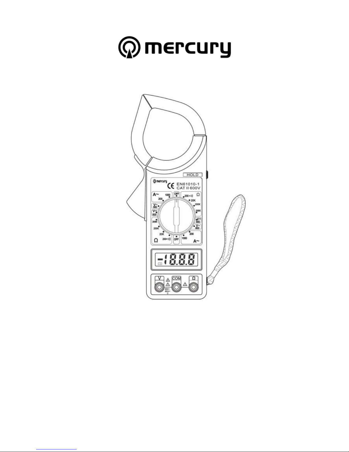
CMT01 User Manual
Multitester compatible table
Transformer
jaw
Trigger
LCD
COM jack
V jack
Data hold
button
Ω jack
Hand
Strap
Page 5
CMT01 User Manual
Model
DCV
ACV
ACA
Ω
CMT01
Y Y Y Y Y
Technical Specifications
Accuracies are guaranteed for 1 year, 23ºC ± 5ºC, less than 80% RH.
DC Voltage
RANGE
RESOLUTION
ACCURACY
200mV
100uV
± (0.5% of rdg + 3D)
2V
1mV
20V
10mV
± (0.8% of rdg + 5D)
200V
100mV
600V
1V
± (1.0% of rdg + 5D)
OVERLOAD PROTECTION: 600Vrms.
AC Voltage
RANGE
RESOLUTION
ACCURACY
200V
100mV
± (1.0% of rdg + 5D)
600V
1V
±(1.2% of rdg + 5D)
Frequency Range: 45Hz ~ 450Hz
Overload Protection: 250Vrms AC
Response: Average, calibrated in rms of sine wave
Audible Continuity
RANGE
DESCRIPTION
Built-in buzzer sounds if resistance
is less than 30±20Ω
Overload Protection: 250V DC/AC rms
Page 6

CMT01 User Manual
AC Current
RANGE
RESOLUTION
ACCURACY (50Hz ~ 60Hz)
20A
10mA
± (2.5% + 13)
200A
100mA
1000A
1A
± (2.5% + 8) @ <800A
For reference only @>800A
Overload Protection: 1200A within 60 seconds.
Jaw Opening: 2.09” (53mm)
Resistance
RANGE
RESOLUTION
ACCURACY
200Ω
0.1Ω
± (1.0% of rdg + 10D)
20kΩ
10Ω
± (1.0% of rdg + 4D)
200kΩ
100Ω
2MΩ
1kΩ
Open Circuit Voltage: about 3V
Overload Protection: 250Vrms DC/AC for 15 sec max
OPERATING INSTRUCTIONS
VOLTAGE MEASUREMENT
1. Connect red test lead to “V” jack, black lead to “COM” jack.
2. Set RANGE switch to desired VOLTAGE position, if the voltage
to be measured is not known beforehand, set switch to the
highest range and reduce it until satisfactory reading is
obtained.
3. Connect test leads to device or circuit being measured.
4. Turn on power of the device or circuit being measured voltage
value will appear on Digital Display along with the voltage
polarity.
Page 7

CMT01 User Manual
CURRENT MEASUREMENT
1. Ensure that “Data Hold” button is not in pressed position.
2. Set range switch to the ACA 1000A range. If the display
indicates one or more leading zeros. Shift to the 200A range
to improve the resolution of the measurement.
3. Press the trigger to open the transformer jaws and clamp
one conductor only, measurements can’t be obtained when
two or more cables are clamped at the same time.
4. Display reading is flow the conductor AC current.
RESISTANCE MEASUREMENT
1. Connect red lead to “Ω”, black lead to “COM”.
2. Set the range switch to desired Ω range.
3. If the resistance being measured is connected to a circuit, turn
off power and discharge all capacitors before measurement.
4. Connect test leads to circuit being measured.
5. Read resistance value on Digital Display.
CONTINUITY TEST
1. Connect the BLACK test lead to the “COM” jack and the RED
to the “VΩ” jack (Note: The polarity of the red test lead is
positive “+”).
2. Set the range switch to range
3. Connect the test leads across the load to be measured.
4. If the circuit resistance is lower than about 30±20Ω,
the built-in buzzer will sound.
BATTERY REPLACEMENT
1) Battery and fuse replacement should only be done after the test
leads have been disconnected and power is off.
2) Loosen screw with suitable screwdriver and remove case.
Page 8

CMT01 User Manual
3) The meter is powered by a single 9V PP3 battery. Snap the
battery connector leads to the terminals of a new battery and
reinsert the battery into the case top. Dress the battery leads so
that they will not be pinched between the case bottom and case
top.
Replace the case bottom and reinstall the screw. Never operate the
meter unless the case bottom is fully closed.
ACCESSORIES
Instruction manual
Set of test leads (red and black)
9V PP3 battery
EN61010–1:2010
This product is classed as Electrical or Electronic equipment
and should not be disposed with other household or commercial
waste at the end of its useful life. The goods must be disposed
of according to your local council guidelines.
Errors and omissions excepted.
Copyright© 2014. AVSL Group Ltd.
 Loading...