

Page 1

CA741
Warranty Message
The product you have purchased comes with a limited warranty from Mercury Marine; the
terms of the warranty are set forth in the
ment contains a description of what is covered, what is not covered, the duration of coverage,
how to best obtain warranty coverage, important disclaimers and limitations of damages,
and other related information. Please review this important information.
CB785
Warranty
Sections of this manual. The warranty state-
WARNING
The operator (driver) is responsible for the correct and safe operation of the boat, the
equipment aboard and the safety of all occupants aboard. We strongly recommend
that the operator read this Operation, Maintenance and Warranty Manual and
thoroughly understand the operational instructions for the power package and all
related accessories before the boat is used.
The description and specifications contained herein were in effect at the time this guide was
approved for printing. Mercury Marine, whose policy is one of continuous improvement,
reserves the right to discontinue models at any time, or to change specifications or designs,
without notice and without incurring obligation.
Mercury Marine Fond du Lac, Wisconsin, U.S.A.
Diesel Sterndrives - Bravo One/Two/Three
1999, Mercury Marine
The following are registered trademarks of Brunswick Corporation:
Autoblend, Jet-Prop, Mariner, Merc, MerCathode, MerCruiser,
Mercury, Mercury Marine, Quicksilver, Ride-Guide, and Thruster.
Printed in U.S.A.
1999, Mercury Marine 90861181990 999
Page 2

CA753
Welcome!
You have selected one of the finest marine power packages available. It incorporates numerous design features
to assure operating ease and durability.
With proper care and maintenance, you will thoroughly enjoy using this product for many boating seasons. To
ensure maximum performance and carefree use, we ask that you thoroughly read this manual.
The Operation, Maintenance and Warranty Manual contains specific instructions for using and maintaining your
product. W e suggest that this manual remain with the product for ready reference whenever you are on the water.
Thank you for purchasing one of our MerCruiser products. We sincerely hope your boating will be pleasant!
Consumer Affairs Department
2
Page 3
CD446
1.
Identification Record
PLEASE RECORD THE FOLLOWING INFORMATION:
Engine Model and Horsepower
Engine Serial Number
2.
Transom Assembly Serial Number (Sterndrive)
Gear Ratio Sterndrive Unit Serial Number
3.
Transmission Model (Inboard)
Gear Ratio Transmission Serial Number
4.
Propeller Number Pitch Diameter
5.
Hull Identification Number (HIN) Purchase Date
6.
Boat Manufacturer
Boat Model Length
7.
Exhaust Gas Emissions Certificate Number (Europe Only)
CB783
Serial Numbers
The serial numbers are the manufacturer’s keys to numerous engineering details which apply to your MerCruiser
model and serial numbers.
power package. When contacting your Authorized MerCruiser Dealer about service, always specify
2
76454
3
74849
3
Page 4

CB786
TABLE OF CONTENTS
Page
Warranty Message 1. . . . . . . . . . . . . . . . . . . . . . . . . . . . . . . . . . . . . . . . . . . . . . . . . . . . . . . . . . . . . . . . . . . . . . . . . . . .
Welcome! 2. . . . . . . . . . . . . . . . . . . . . . . . . . . . . . . . . . . . . . . . . . . . . . . . . . . . . . . . . . . . . . . . . . . . . . . . . . . . . . . . . . . .
Serial Numbers 3. . . . . . . . . . . . . . . . . . . . . . . . . . . . . . . . . . . . . . . . . . . . . . . . . . . . . . . . . . . . . . . . . . . . . . . . . . . . . . .
Table Of Contents 4. . . . . . . . . . . . . . . . . . . . . . . . . . . . . . . . . . . . . . . . . . . . . . . . . . . . . . . . . . . . . . . . . . . . . . . . . . . . .
Warranty Information 6
Owner Warranty Registration 6. . . . . . . . . . . . . . . . . . . . . . . . . . . . . . . . . . . . . . . . . . . . . . . . . . . . . . . . . . . . . . . . . .
International Owner Registration 7. . . . . . . . . . . . . . . . . . . . . . . . . . . . . . . . . . . . . . . . . . . . . . . . . . . . . . . . . . . . . . .
Recreational Use Diesel Sterndrive Limited Warranty 8. . . . . . . . . . . . . . . . . . . . . . . . . . . . . . . . . . . . . . . . .
Warranty Coverage and Exclusion 10. . . . . . . . . . . . . . . . . . . . . . . . . . . . . . . . . . . . . . . . . . . . . . . . . . . . . . . . . .
Transferable Warranty 11. . . . . . . . . . . . . . . . . . . . . . . . . . . . . . . . . . . . . . . . . . . . . . . . . . . . . . . . . . . . . . . . . . . . . . . .
Read This Manual Thoroughly 12
General Information 13
Lanyard Stop Switch 13. . . . . . . . . . . . . . . . . . . . . . . . . . . . . . . . . . . . . . . . . . . . . . . . . . . . . . . . . . . . . . . . . . . . . . . .
Wave And Wake Jumping 14. . . . . . . . . . . . . . . . . . . . . . . . . . . . . . . . . . . . . . . . . . . . . . . . . . . . . . . . . . . . . . . . . . .
Impact With Underwater Hazards 15. . . . . . . . . . . . . . . . . . . . . . . . . . . . . . . . . . . . . . . . . . . . . . . . . . . . . . . . . . . . .
Operating With Low Water Inlets In Shallow Water 16. . . . . . . . . . . . . . . . . . . . . . . . . . . . . . . . . . . . . . . . . . . . . .
Safe Boating Suggestions 17. . . . . . . . . . . . . . . . . . . . . . . . . . . . . . . . . . . . . . . . . . . . . . . . . . . . . . . . . . . . . . . . . . .
Protecting People In The Water 18. . . . . . . . . . . . . . . . . . . . . . . . . . . . . . . . . . . . . . . . . . . . . . . . . . . . . . . . . . . . . . .
While You Are Cruising 18. . . . . . . . . . . . . . . . . . . . . . . . . . . . . . . . . . . . . . . . . . . . . . . . . . . . . . . . . . . . . . . . . . . . . .
While Boat Is Stationary 18. . . . . . . . . . . . . . . . . . . . . . . . . . . . . . . . . . . . . . . . . . . . . . . . . . . . . . . . . . . . . . . . . . . . .
High-Speed And High-Performance Boat Operation 18. . . . . . . . . . . . . . . . . . . . . . . . . . . . . . . . . . . . . . . . . . . . .
Conditions Affecting Operation 19
Weight Distribution 19. . . . . . . . . . . . . . . . . . . . . . . . . . . . . . . . . . . . . . . . . . . . . . . . . . . . . . . . . . . . . . . . . . . . . . . . . .
Bottom Of Boat 19. . . . . . . . . . . . . . . . . . . . . . . . . . . . . . . . . . . . . . . . . . . . . . . . . . . . . . . . . . . . . . . . . . . . . . . . . . . . .
Cavitation 19. . . . . . . . . . . . . . . . . . . . . . . . . . . . . . . . . . . . . . . . . . . . . . . . . . . . . . . . . . . . . . . . . . . . . . . . . . . . . . . . .
Ventilation 19. . . . . . . . . . . . . . . . . . . . . . . . . . . . . . . . . . . . . . . . . . . . . . . . . . . . . . . . . . . . . . . . . . . . . . . . . . . . . . . . .
Propeller Selection 20. . . . . . . . . . . . . . . . . . . . . . . . . . . . . . . . . . . . . . . . . . . . . . . . . . . . . . . . . . . . . . . . . . . . . . . . . .
How Elevation And Climate Affect Performance 20. . . . . . . . . . . . . . . . . . . . . . . . . . . . . . . . . . . . . . . . . . . . . . . .
Important Information 21
Operation and Maintenance 21. . . . . . . . . . . . . . . . . . . . . . . . . . . . . . . . . . . . . . . . . . . . . . . . . . . . . . . . . . . . . . . . . .
Sterndrive Unit 10-Hour Break-In Period 21. . . . . . . . . . . . . . . . . . . . . . . . . . . . . . . . . . . . . . . . . . . . . . . . . . . . . . .
End of First Season Checkup 21. . . . . . . . . . . . . . . . . . . . . . . . . . . . . . . . . . . . . . . . . . . . . . . . . . . . . . . . . . . . . . . .
Freezing Temperature And Cold Weather Operation 22. . . . . . . . . . . . . . . . . . . . . . . . . . . . . . . . . . . . . . . . . . . . .
Drive Unit Impact Protection 22. . . . . . . . . . . . . . . . . . . . . . . . . . . . . . . . . . . . . . . . . . . . . . . . . . . . . . . . . . . . . . . . .
Drain Plug and Bilge Pump 22. . . . . . . . . . . . . . . . . . . . . . . . . . . . . . . . . . . . . . . . . . . . . . . . . . . . . . . . . . . . . . . . . .
Trailering Boat 22. . . . . . . . . . . . . . . . . . . . . . . . . . . . . . . . . . . . . . . . . . . . . . . . . . . . . . . . . . . . . . . . . . . . . . . . . . . . .
Launching And Boat Operation Care 23. . . . . . . . . . . . . . . . . . . . . . . . . . . . . . . . . . . . . . . . . . . . . . . . . . . . . . . . . .
Stolen Sterndrive Unit 23. . . . . . . . . . . . . . . . . . . . . . . . . . . . . . . . . . . . . . . . . . . . . . . . . . . . . . . . . . . . . . . . . . . . . . .
Do-It-Yourself Maintenance Suggestions 24. . . . . . . . . . . . . . . . . . . . . . . . . . . . . . . . . . . . . . . . . . . . . . . . . . . . . . .
Operation 26
Remote Controls (Panel Mounted) 27. . . . . . . . . . . . . . . . . . . . . . . . . . . . . . . . . . . . . . . . . . . . . . . . . . . . . . . . . . . .
Remote Controls (Console Mounted) 27. . . . . . . . . . . . . . . . . . . . . . . . . . . . . . . . . . . . . . . . . . . . . . . . . . . . . . . . . .
Remote Controls (Two Lever) 29. . . . . . . . . . . . . . . . . . . . . . . . . . . . . . . . . . . . . . . . . . . . . . . . . . . . . . . . . . . . . . . .
Power Trim 29. . . . . . . . . . . . . . . . . . . . . . . . . . . . . . . . . . . . . . . . . . . . . . . . . . . . . . . . . . . . . . . . . . . . . . . . . . . . . . . .
Shifting 34. . . . . . . . . . . . . . . . . . . . . . . . . . . . . . . . . . . . . . . . . . . . . . . . . . . . . . . . . . . . . . . . . . . . . . . . . . . . . . . . . . . .
Specifications 35
4
Page 5

Page
Maintenance 36
General Maintenance Information 37. . . . . . . . . . . . . . . . . . . . . . . . . . . . . . . . . . . . . . . . . . . . . . . . . . . . . . . . . . . . .
Maintenance Aids 37. . . . . . . . . . . . . . . . . . . . . . . . . . . . . . . . . . . . . . . . . . . . . . . . . . . . . . . . . . . . . . . . . . . . . . . . . .
Routine Maintenance 38. . . . . . . . . . . . . . . . . . . . . . . . . . . . . . . . . . . . . . . . . . . . . . . . . . . . . . . . . . . . . . . . . . . . . . .
Scheduled Maintenance 38. . . . . . . . . . . . . . . . . . . . . . . . . . . . . . . . . . . . . . . . . . . . . . . . . . . . . . . . . . . . . . . . . . . . .
Checking Drive Unit Oil 39. . . . . . . . . . . . . . . . . . . . . . . . . . . . . . . . . . . . . . . . . . . . . . . . . . . . . . . . . . . . . . . . . . . . . .
Power Trim Pump Fluid 39. . . . . . . . . . . . . . . . . . . . . . . . . . . . . . . . . . . . . . . . . . . . . . . . . . . . . . . . . . . . . . . . . . . . . .
Changing Drive Unit Oil 41. . . . . . . . . . . . . . . . . . . . . . . . . . . . . . . . . . . . . . . . . . . . . . . . . . . . . . . . . . . . . . . . . . . . .
Lubrication 43. . . . . . . . . . . . . . . . . . . . . . . . . . . . . . . . . . . . . . . . . . . . . . . . . . . . . . . . . . . . . . . . . . . . . . . . . . . . . . . . .
Propellers (Bravo One and Two) 45. . . . . . . . . . . . . . . . . . . . . . . . . . . . . . . . . . . . . . . . . . . . . . . . . . . . . . . . . . . . . .
Propellers (Bravo Three) 47. . . . . . . . . . . . . . . . . . . . . . . . . . . . . . . . . . . . . . . . . . . . . . . . . . . . . . . . . . . . . . . . . . . .
Corrosion And Corrosion Protection 49. . . . . . . . . . . . . . . . . . . . . . . . . . . . . . . . . . . . . . . . . . . . . . . . . . . . . . . . . . .
Cold Weather or Extended Storage 52
Sterndrive Unit Lay Up 52. . . . . . . . . . . . . . . . . . . . . . . . . . . . . . . . . . . . . . . . . . . . . . . . . . . . . . . . . . . . . . . . . . . . . .
Sterndrive Unit Recommissioning 52. . . . . . . . . . . . . . . . . . . . . . . . . . . . . . . . . . . . . . . . . . . . . . . . . . . . . . . . . . . . .
Troubleshooting 53
Remote Control Operates Hard, Binds, Has Excessive Free-play Or Makes Unusual Sounds 53. . . . . . . . .
Steering Wheel Turns Hard Or Jerky 53. . . . . . . . . . . . . . . . . . . . . . . . . . . . . . . . . . . . . . . . . . . . . . . . . . . . . . . . . .
Power Trim Does Not Operate (Electric Motor Does Not Run) 53. . . . . . . . . . . . . . . . . . . . . . . . . . . . . . . . . . . .
Power Trim Does Not Operate (Electric Motor Runs But Drive Unit Does Not Move) 53. . . . . . . . . . . . . . . . .
Owner Service Assistance 54
Local Repair Service 54. . . . . . . . . . . . . . . . . . . . . . . . . . . . . . . . . . . . . . . . . . . . . . . . . . . . . . . . . . . . . . . . . . . . . . . .
Service Away From Home 54. . . . . . . . . . . . . . . . . . . . . . . . . . . . . . . . . . . . . . . . . . . . . . . . . . . . . . . . . . . . . . . . . . .
Parts And Accessories Inquiries 54. . . . . . . . . . . . . . . . . . . . . . . . . . . . . . . . . . . . . . . . . . . . . . . . . . . . . . . . . . . . . .
Resolving A Problem 54. . . . . . . . . . . . . . . . . . . . . . . . . . . . . . . . . . . . . . . . . . . . . . . . . . . . . . . . . . . . . . . . . . . . . . . .
Mercury Marine Service Offices 55. . . . . . . . . . . . . . . . . . . . . . . . . . . . . . . . . . . . . . . . . . . . . . . . . . . . . . . . . . . . . .
Customer Service Literature 56. . . . . . . . . . . . . . . . . . . . . . . . . . . . . . . . . . . . . . . . . . . . . . . . . . . . . . . . . . . . . . . . .
Owner’s Logbook 57
5
Page 6

CD54
Warranty Information
CD55
Owner Warranty Registration
UNITED STATES AND CANADA ONLY
• It is important that your selling dealer fills out the Warranty Registration Card completely and mails it to the
factory immediately upon sale of the new product.
• It identifies name and address of the original purchaser, product model and serial number(s), date of sale,
type of use and selling dealer’s code, name and address. The dealer also certifies that you are the original
purchaser and user of the product.
• Upon receipt of the Warranty Registration Card at the factory, you will be issued a plastic Owner Warranty
Registration Card which is your only valid registration identification. It must be presented to the servicing dealer should warranty service be required. Warranty claims will not be accepted without presentation of this card.
• A temporary Owner Warranty Registration Card will be presented to you when you purchase the product It
is valid only for 30 days from date of sale while your plastic Owner Warranty Registration Card is being processed. Should your product need service during this period, present the temporary registration card to the
dealer. He will attach it to your warranty claim form.
• Because of your selling dealer’s continuing personal interest in your satisfaction, the product should be re-
turned to him for warranty service.
• If your plastic card is not received within 30 days from date of new product sale, please contact your selling
dealer.
• The product warranty is not effective until the product is registered at the factory.
• NOTICE: Registration lists must be maintained by factory and dealer on marine products sold in the United
States, should notification under the Federal Boat Safety Act be required.
6
Page 7

CD56
International Owner Registration
OUTSIDE THE UNITED STATES AND CANADA
• It is important that your selling dealer fills out the Warranty Registration Card completely and mails it to the
distributor or Marine Power Service Center responsible for administering the warranty registration/claim program for your area.
• The W arranty Registration Card identifies your name and address, product model and serial number(s), date
of sale, type of use and the selling distributors/dealer’s code number, name and address. The distributor/dealer also certifies that you are the original purchaser and user of the product.
• A copy of the Warranty Registration Card, designated as the “Purchaser’s Copy”, MUST be given to you im-
mediately after the card has been completely filled out by the selling distributor/dealer. This card represents
your factory registration identification, and should be retained by you for future use when required Should you
ever require warranty service on this product, your dealer may ask you for the Warranty Registration Card
to verify date of purchase and to use the information on the card to prepare the warranty claim form(s).
• In some countries, the Marine Power Service Center will issue you a permanent (plastic) Warranty Registra-
tion Card within 30 days after receiving the “Factory Copy” of the Warranty Registration Card from your distributor/dealer If you receive a plastic Warranty Registration Card, you may discard the “Purchaser’s Copy” that
you received from the distributor/dealer when you purchased the product. Ask your distributor/dealer if this
plastic card program applies to you.
• For further information concerning the Warranty Registration Card and its relationship to Warranty Claim pro-
cessing, refer to the “International Warranty.” Refer to “Table of Contents.”
IMPORTANT: Registration lists must be maintained by the factory and dealer in some countries by law.
It is our desire to have ALL products registered at the factory should it ever be necessary to contact you.
Make sure your dealer/distributor fills out the warranty registration card immediately and sends the factory copy to the Marine Power International Service Center for your area.
7
Page 8

CD613
Recreational Use Diesel Sterndrive Limited Warranty
I. WHAT IS COVERED
Mercury Marine warrants its new products to be free of defects in material and workmanship during
the period described below.
II. DURATION OF COVERAGE
This Limited Warranty provides coverage for one (1) year from the date the product is first sold to a
recreational use retail purchaser, or the date on which the product is first put into service, whichever
occurs first. Commercial use of the product voids the warranty. Commercial use is defined as any work
or employment related use of the product, or any use of the product which generates income, for any
part of the warranty period, even if the product is only occasionally used for such purposes. The repair
or replacement of parts, or the performance of service under this warranty, does not extend the life of
this warranty beyond its original expiration date. Unexpired warranty coverage can be transferred to
a subsequent purchaser upon proper re-registration of the product.
III. CONDITIONS THAT MUST BE MET IN ORDER TO OBTAIN WARRANTY COVERAGE
Warranty coverage is available only to retail customers that purchase from a Dealer authorized by Mercury Marine to distribute the product in the country in which the sale occurred, and then only after the
Mercury Marine specified pre-delivery inspection process is completed and documented. Warranty
coverage becomes available upon proper registration of the product by the authorized dealer. Inaccurate warranty registration information regarding recreational use, or subsequent change of use from
recreational to commercial may void the warranty at the sole discretion of Mercury Marine. Routine
maintenance outlined in the Operation, Maintenance and Warranty Manual must be timely performed
in order to obtain warranty coverage. If this maintenance is performed by the retail customer Mercury
Marine reserves the right to make future warranty coverage contingent on proof of proper maintenance.
IV. WHAT MERCURY WILL DO
Mercury’s sole and exclusive obligation under this warranty is limited to, at our option, repairing a defective part, replacing such part or parts with new or Mercury Marine certified re-manufactured parts,
or refunding the purchase price of the Mercury product. Mercury reserves the right to improve or modify
products from time to time without assuming an obligation to modify products previously manufactured.
V. HOW TO OBTAIN WARRANTY COVERAGE
The customer must provide Mercury with a reasonable opportunity to repair, and reasonable access
to the product for warranty service. Warranty claims shall be made by delivering the product for inspection to a Mercury dealer authorized to service the product. If purchaser cannot deliver the product to
such a dealer, written notice must be given to Mercury . We will then arrange for the inspection and any
covered repair. Purchaser in that case shall pay for all related transportation charges and/or travel
time. If the service provided is not covered by this warranty, purchaser shall pay for all related labor
and material, and any other expenses associated with that service. Purchaser shall not, unless requested by Mercury, ship the product or parts of the product directly to Mercury. The warranty registration card is the only valid registration identification and must be presented to the dealer at the time
warranty service is requested in order to obtain coverage.
8
Page 9

VI. WHAT IS NOT COVERED
This limited warranty does not cover routine maintenance items, tune ups, adjustments, normal wear
and tear, damage caused by abuse, abnormal use, use of a propeller or gear ratio that does not allow
the engine to run in its recommended rpm range (see the Operation, Maintenance and Warranty
Manual), operation of the product in a manner inconsistent with the recommended operation/duty
cycle section of the Operation, Maintenance and Warranty Manual, neglect, accident, submersion,
improper installation (proper installation specifications and techniques are set forth in the installation
instructions for t h e product), improper service, use of an accessory or part which damages the Mercury
product and was not manufactured or sold by us, jet pump impellers and liners, operation with fuels,
oils or lubricants which are not suitable for use with the product (see the Operation, Maintenance and
Warranty Manual), alteration or removal of parts, or water entering the engine through the fuel intake,
air intake or exhaust system. Use of the product for racing or other competitive activity, or operating
with a racing type lower unit, at any point, even by a prior owner of the product, voids the warranty.
VII. Expenses related to haul-out, launch, towing, storage, telephone, rental, inconvenience, slip fees, in-
surance cov e r age, loan payments, loss of time, loss of income, or any other type of incidental or consequential damages are not covered by this warranty . Also, expenses associated with the removal and/
or replacement of boat partitions or material caused by boat design for access to the product are not
covered by this warranty.
VIII. No individual or entity, including Mercury Marine authorized dealers, has been given authority by Mer-
cury Marine to make any affirmation, representation or warranty regarding the product, other than
those contained in this limited warranty , and if made, shall not be enforceable against Mercury Marine.
IX. For additional information regarding events and circumstances covered by this warranty, and those
that are not, see the W arranty Coverage section of the Operation, Maintenance and Warranty Manual,
incorporated by reference into this warranty.
X. DISCLAIMERS AND LIMITATIONS
THE IMPLIED WARRANTIES OF MERCHANTABILITY AND FITNESS FOR A PARTICULAR PURPOSE ARE EXPRESSLY DISCLAIMED. TO THE EXTENT THAT THEY CANNOT BE DISCLAIMED, THE IMPLIED WARRANTIES ARE LIMITED IN DURATION TO THE LIFE OF THE EXPRESS WARRANTY. INCIDENTAL AND CONSEQUENTIAL DAMAGES ARE EXCLUDED FROM
COVERAGE UNDER THIS WARRANTY. SOME ST ATES/COUNTRIES DO NOT ALLOW FOR THE
DISCLAIMERS, LIMITATIONS AND EXCLUSIONS IDENTIFIED ABOVE, AS A RESULT, THEY
MA Y NOT APPLY TO YOU. THIS WARRANTY GIVES YOU SPECIFIC LEGAL RIGHTS, AND YOU
MAY ALSO HAVE OTHER LEGAL RIGHTS WHICH VARY FROM STATE TO STATE AND COUNTRY TO COUNTRY.
9
Page 10

CD621
Warranty Coverage and Exclusions
The purpose of this section is to help eliminate some of the more common misunderstandings regarding warranty coverage. The following list explains some of the types of services that are not covered by warranty.
Keep in mind that warranty covers repairs that are needed within the warranty period because of defects in material and workmanship. Installation errors, accidents, normal wear and a variety of other causes that affect the
product are not covered.
Warranty is limited to defects in material or workmanship, but only when the customer purchases or obtains predelivery service from a Dealer authorized by us to distribute Mercury MerCruiser Product in the country in which
the sale or predelivery service occurred.
Should you have any questions concerning warranty coverage contact your authorized dealer. They will be
pleased to answer any questions that you may have.
WARRANTY DOES NOT APPLY TO THE FOLLOWING:
• Minor adjustments or checks, including controls, and checking lubrication made in connection with normal
services.
• Damage caused by neglect, lack of maintenance, accident, abnormal operation, improper installation or ser-
vice, or freezing temperatures.
• Haul-out, launch, towing charges; removal and/or replacement of boat partitions or material because of boat
design for necessary access to the product; all related transportation charges and/or travel time, etc. Reasonable access must be provided to the product for warranty service. Customer must deliver product to an Authorized Dealer.
• Additional service work requested by customer other than that necessary to satisfy the warranty obligation.
• Labor performed by other than an Authorized Dealer may be covered only under following circumstances:
When performed on emergency basis (providing there are no Authorized Dealers in area who can perform
the work required or have no facilities to haul out, etc., and prior factory approval has been given to have the
work performed at this facility).
• All incidental and/or consequential damages (storage charges, telephone or rental charges of any type, in-
convenience or loss of time or income) are the owner’s responsibility.
• Use of other than Quicksilver replacement parts when making warranty repairs.
• Oils, lubricants or fluids changed as a matter of normal maintenance is customer’s responsibility unless loss
or contamination of same is caused by product failure that would be eligible for warranty consideration.
• Participating in or preparing for racing or other competitive activity.
• Lower unit and/or propeller damage caused by striking a submerged object is considered a marine hazard.
• Failure of any parts caused by lack of cooling water, which results from starting power package out of water,
foreign material blocking inlets or power package being mounted too high.
• Use of lubricants which are not suitable for use with or on the product.
• Our limited warranty does not apply to any damage to our products caused by the installation or use of parts
and accessories which are not manufactured or sold by us. Failures which are not related to the use of those
parts or accessories, are covered under warranty, if they otherwise meet the terms of the limited warranty for
that product.
10
Page 11

CD618
Transferable Warranty
The product warranty is transferable to a subsequent purchaser, but only for the remainder of the unused portion
of the limited warranty. This will not apply to products used for commercial applications.
DIRECT SALE BY OWNER
•
The second owner can be registered as the new owner and retain the unused portion of the limited warranty
by sending the former owner’s plastic Owner Warranty Registration Card and a copy of the bill of sale to show
proof of ownership. In the United States and Canada, mail to:
Mercury Marine
W6250 West Pioneer Road
P.O. Box 1939
Fond du Lac, Wl 54936-1939
Attn: Warranty Registration Department
• A new Owner Warranty Registration Card will be issued with the new owner’s name and address. Registration
records will be changed on the factory computer registration file.
• There is no charge for this service.
Outside the United States and Canada, please contact the Mercury Marine Service Office in your country,
or the factory branch or distributor closet to you, for the transferable warranty procedure that would apply to you.
11
Page 12
CD614
Read This Manual Thoroughly
IF YOU DON’T UNDERSTAND ANY PORTION, CONTACT YOUR DEALER FOR A DEMONSTRATION OF
ACTUAL STARTING AND OPERATING PROCEDURES.
NOTICE
Throughout this publication, and on your power package, WARNINGS and CAUTIONS, accompanied by the
International Hazard Symbol
particular service or operation that may be hazardous if performed incorrectly or carelessly. Observe them
carefully.
These “Safety Alerts” alone cannot eliminate the hazards that they signal. Strict compliance with these special
instructions while performing the service, plus “common sense” operation, are major accident prevention
measures.
Hazards or unsafe practices which could result in severe personal injury or death.
Hazards or unsafe practices which could result in minor personal injury or product or property
damage.
, may be used to alert the installer/user to special instructions concerning a
!
WARNING
CAUTION
IMPORTANT: Indicates information or instructions that are necessary for proper operation and/or
maintenance.
12
Page 13
CA619
Lanyard Stop Switch
General Information
2
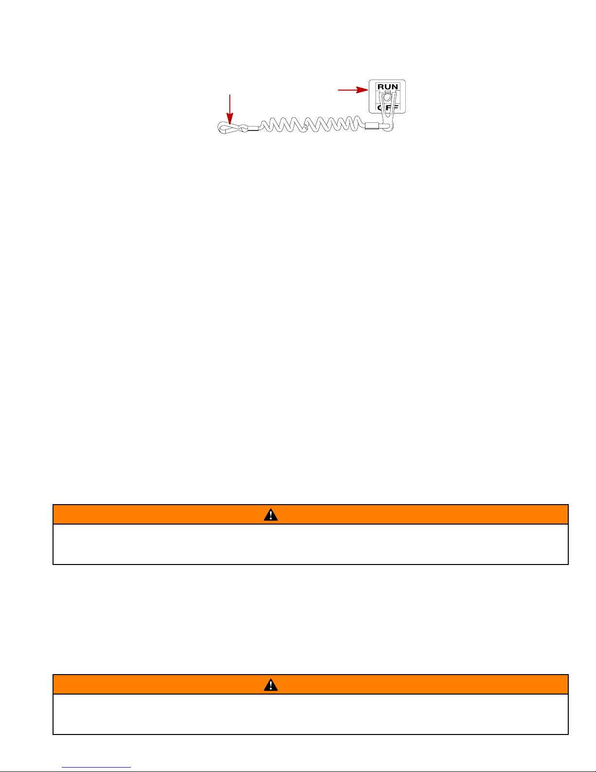
The purpose of a lanyard stop switch (1) is to turn off the engine when the operator moves far enough away from
the operator’s position (as in accidental ejection from the operator’s position) to activate the switch. Some remote
control units are equipped with a lanyard stop switch. A lanyard stop switch can be installed on the dashboard
or side adjacent to the operator’s position.
The lanyard is a cord usually between 4 and 5 feet (1220 and 1524 mm) in length when stretched out with an
element on one end made to be inserted into the switch and a snap (2) on the other end for attaching to the
operator. The lanyard is coiled to make its at-rest condition as short as possible so as to minimize the likelihood
of lanyard entanglement with nearby objects. It is made as long as it is in its stretched condition to minimize the
likelihood of accidental activation should the operator choose to move around in an area close to the normal
operator’s position. If it is desired to have a shorter lanyard, wrap the lanyard around the operator’s wrist or leg,
or tie a knot in the lanyard.
IMPORTANT: The purpose of a lanyard stop switch is to stop the engine when the operator moves far
enough away from the operator’s position to activate the switch. This would occur if the operator
accidentally falls overboard or moves within the boat a sufficient distance from the operator’s position.
Accidental ejections and falls overboard are more likely to occur in certain types of boats such as low
sided sport boats or bass boats, and high-performance boats. Accidental ejections and falls overboard
are also likely to occur as a result of poor operating practices such as sitting on the back of the seat or
gunwale at planing speeds, standing at planing speeds, sitting on elevated fishing boat decks, operating
at planing speeds in shallow or obstacle-infested waters, releasing your grip on a steering wheel that
is pulling in one direction, drinking alcohol or consuming drugs, or daring, high-speed boat maneuvers.
1
74608
While activation of the lanyard stop switch will stop the engine immediately , a boat will continue to coast for some
distance depending upon the velocity and degree of any turn at shut-down. However, the boat will not complete
a full circle. While the boat is coasting, it can cause injury to anyone in the boat’s path as seriously as the boat
would when under power.
We strongly recommend that other occupants be instructed on proper starting and operating procedures should
they be required to operate the engine in an emergency (e.g. if the operator is accidentally ejected).
WARNING
Should the operator fall out of the boat, the possibility of serious injury or death from being run over
by the boat can be greatly reduced by stopping the engine immediately. Always properly connect both
ends of the stop switch lanyard to the stop switch and the operator.
Accidental or unintended activation of the switch during normal operation is also a possibility. This could cause
any, or all, of the following potentially hazardous situations:
1 Occupants could be thrown forward due to unexpected loss of forward motion – a particular concern for
passengers in the front of the boat who could be ejected over the bow and possibly struck by the gear case or
propeller.
2 Loss of power and directional control in heavy seas, strong current or high winds.
3 Loss of control when docking.
WARNING
Avoid serious injury or death from deceleration forces resulting from accidental or unintended stop
switch activation. The boat operator should never leave the operator’s station without first
disconnecting the stop switch lanyard from the operator.
13
Page 14
CD543
Wave And Wake Jumping
Operating recreational boats over waves and wakes is a natural part of boating. However, when this activity is
done with speed to force the boat hull partially or completely out of the water, certain hazards arise, particularly
when the boat re-enters the water.
The primary concern is the boat changing direction while in the midst of the jump. In such case the landing may
cause the boat to violently veer in a new direction. Such a sharp change in direction or turn can cause occupants
to be thrown out of their seats or out of the boat.
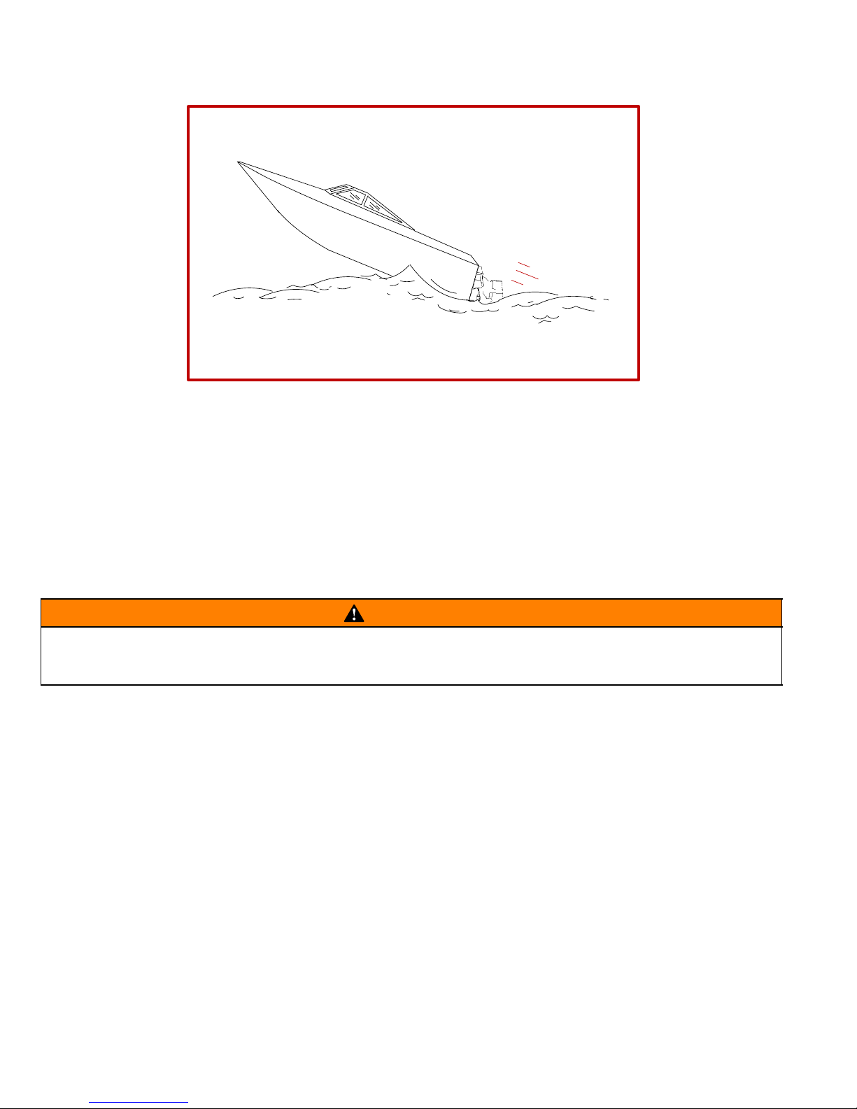
There is another less common hazardous result from allowing your boat to launch off a wave or wake. If the bow
of your boat pitches down far enough while airborne, upon water contact it may penetrate under the water surface
and “submarine” for an instant. This will bring the boat nearly to a stop in an instant and can send the occupants
flying forward. The boat may also steer sharply to one side.
WARNING
Avoid serious injury or death from being thrown within or out of a boat when it lands after jumping a
wave or wake. Avoid wave or wake jumping whenever possible. Instruct all occupants that if a wake
or wave jump occurs, get low and hang on to any boat hand hold.
14
Page 15
CD544
Impact With Underwater Hazards
Reduce speed and proceed with caution whenever you’re driving a boat in shallow water areas or in areas where
the waters are suspected of having underwater obstacles that could be struck by the sterndrive or the boat bottom. The most important thing you can do to help reduce injury or impact damage from striking a floating
or underwater object is control the boat speed. Under these conditions, boat speed should be kept to
a minimum planing speed of (15 to 25 MPH).
Striking a floating/underwater object may result in an infinite number of situations. Some of these situations could
result in the following:
• The boat could move suddenly in a new direction. Such a sharp change in direction or turn can cause occu-
pants to be thrown out of their seats or out of the boat.
• A rapid reduction in speed. This will cause occupants to be thrown forward, even out of the boat.
• Impact damage to the sterndrive and/or boat.
Keep in mind, one of the most important things you can do to help reduce injury or impact damage in these situations is control the boat speed. Boat speed should be kept to a minimum planing speed when driving in waters
known to have underwater obstacles.
After striking a submerged object, stop engine as soon as possible and inspect the sterndrive unit for any broken
or loose parts. If damage is present or suspected, the power package should be taken to an authorized dealer
for a thorough inspection and necessary repair.
The boat should also be checked for any hull fractures, transom fractures, water leaks.
Operating a damaged sterndrive could cause additional damage to other parts of the power package, or could
affect control of the boat. If continued running is necessary, do so at greatly reduced speeds.
WARNING
Avoid serious injury or death from loss of boat control. Continued boating with major impact damage
can result in sudden component failure with or without subsequent impacts. Have the power package
thoroughly inspected and any necessary repairs made.
15
Page 16
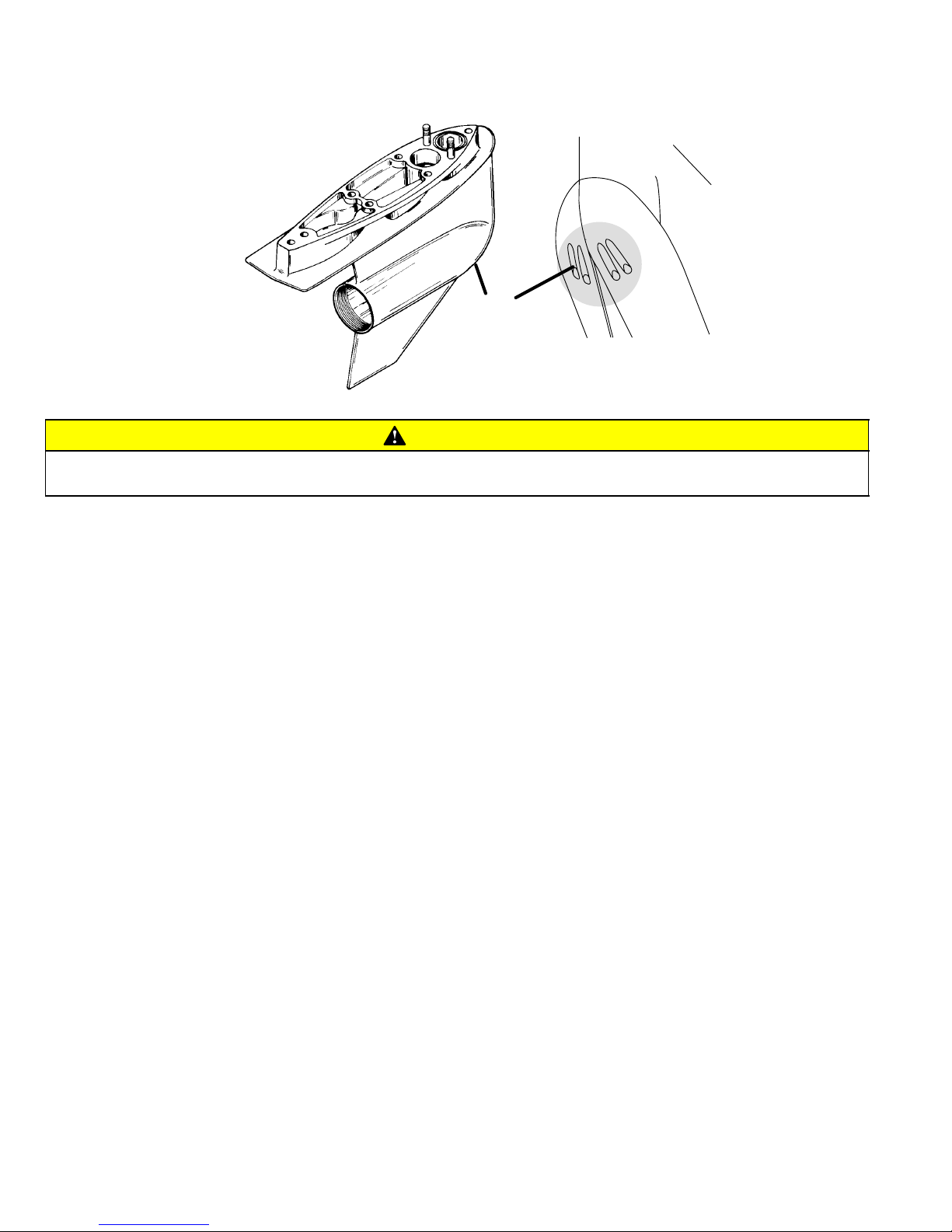
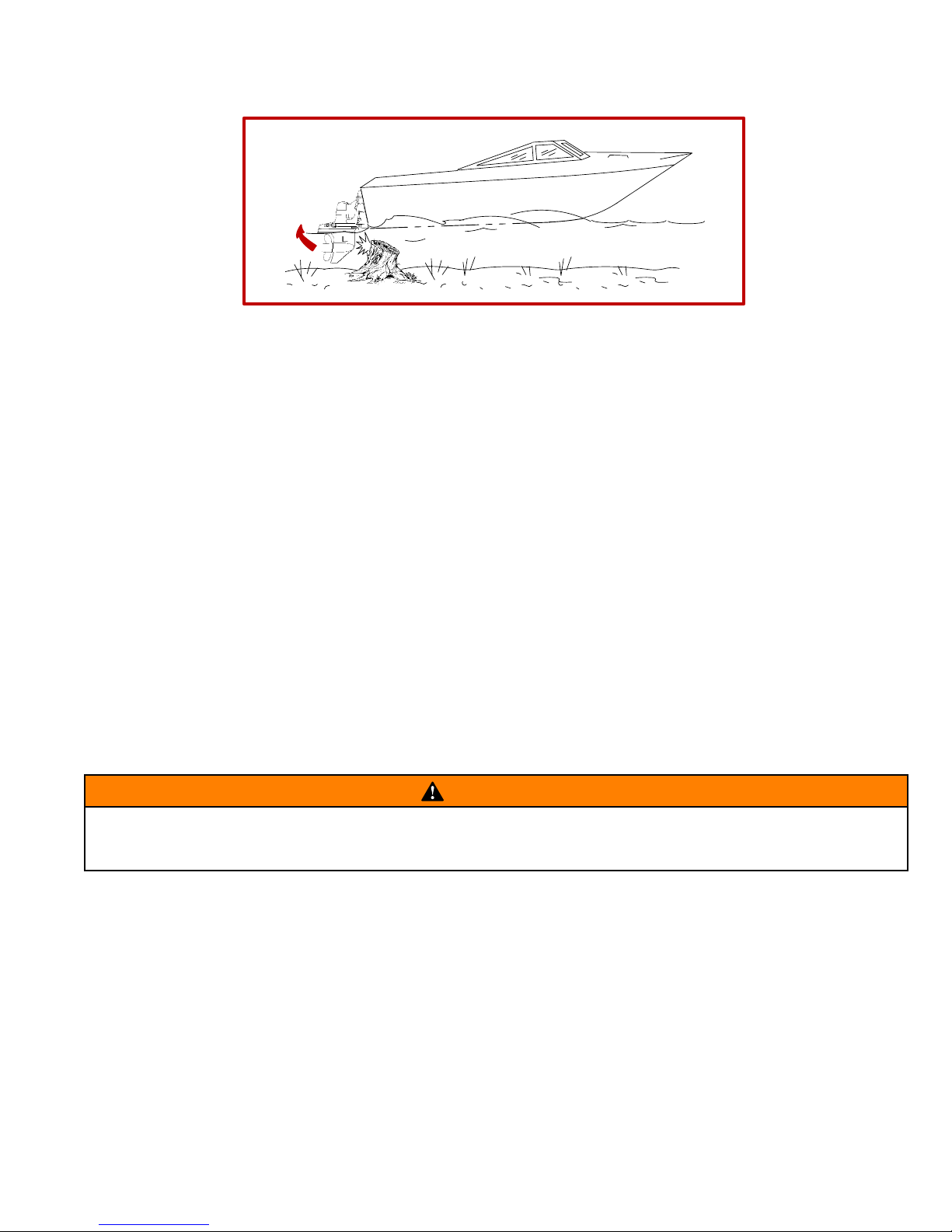
CA802
Operating With Low Water Inlets In Shallow Water
A
76363
75827
CAUTION
Serious engine damage could occur by failing to follow these instructions. Sand, silt or mud could be
sucked into the water inlets restricting or shutting off the water supply to the engine.
Extreme care should be exercised when operating a boat equipped with low water inlets (A) while maneuvering
in shallow water. Also, avoid beaching the boat with the engine(s) running.
16
Page 17

CA281
Safe Boating Suggestions
In order to safely enjoy the waterways, familiarize yourself with local and other governmental boating regulations
and restrictions, and consider the following suggestions.
• Know and obey all nautical rules and laws of the waterways. Boat operators should complete a boating
safety course. Courses are offered in the U.S.A. by (1) The U.S. Coast Guard Auxiliary, (2) The Power Squadron, (3) The Red Cross and (4) your state or provincial boating law enforcement agency. Inquiries may be
made to the Boating Hotline, 1-800-368-5647 or the Boat U.S. Foundation information number
1-800-336-BOAT.
We strongly recommend that all powerboat operators attend one of these courses.
You should also review the NMMA Sources of Waterway Information booklet. It lists regional sources of safety,
cruising and local navigation and is available at no charge by writing to:
Sources of Waterway Information
National Marine Manufacturers Association
410 N. Michigan Avenue
Chicago, IL 60611 U.S.A.
• Perform safety checks and required maintenance. Follow a regular schedule and ensure that all repairs
are properly made.
• Check safety equipment on board. Here are suggestions of the types of safety equipment to carry when
boating:
(1) Approved fire extinguisher(s); paddle or oar.
(2) Signal devices: flashlight, rockets or flares, flag and whistle or horn.
(3) Spare propeller, thrust hubs and an appropriate wrench.
(4) Tools for necessary minor repairs; first aid kit and book.
(5) Anchor and extra anchor line; water-proof storage containers.
(6) Manual bilge pump and extra drain plugs; compass and map or chart of area.
(7) Spare operating equipment; batteries, bulbs, fuses, etc.
(8) Transistor radio
(9) Drinking water
• Know signs of weather change and avoid foul weather and rough-sea boating.
• Tell someone where you are going and when you expect to return.
• Passenger boarding. Stop the engine whenever passengers are boarding, unloading or are near the back
(stern) of the boat. Just shifting the drive unit into neutral is not sufficient.
• Use personal flotation devices. Federal Law requires that there be a U. S. Coast Guard approved, wear-
able-type life jacket (personal flotation device), correctly sized and readily accessible for every person on
board, plus a throwable cushion or ring. W e strongly advise that everyone wear a life jacket at all times while
in the boat.
• Prepare other boat operators. Instruct at least one person on board in the basics of starting and operating
the engine and boat handling in case the driver becomes disabled or falls overboard.
• Do not overload your boat. Most boats are rated and certified for maximum load (weight) capacities (refer
to your boat capacity plate). When in doubt, contact your dealer or the boats manufacturer. Know your boat’s
operating and loading limitations.
• Make sure everyone in the boat is properly seated. Don’t allow anyone to sit or ride on any part of the boat
that was not intended for such use. This includes backs of seats, gunwales, transom, bow, decks, raised fish-
ing seats, any rotating fishing seat; anywhere that sudden unexpected acceleration, sudden stopping, unex-
pected loss of boat control or sudden boat movement could cause a person to be thrown overboard or into
the boat.
17
Page 18

• Never be under the influence of alcohol or drugs while boating (it is the law). They impair your judgment
and greatly reduce your ability to react quickly.
• Know your boating area and avoid hazardous locations.
• Be alert. The operator of the boat is responsible by law to “maintain a proper lookout by sight (and hearing).”
The operator must have an unobstructed view particularly to the front. No passengers, load, or fishing seats
should block the operators view when operating the boat above idle or planing transition speed. Watch “the
other guy,” the water and your wake.
• Never drive your boat directly behind a water skier in case the skier falls. As an example, your boat trav-
eling at 25 miles per hour (40 km/hr) in 5 seconds will overtake a fallen skier who was 200 feet in front of you.
• Watch fallen skiers. When using your boat for water skiing or similar activities, always keep a fallen or down
skier on the operator’s side of the boat while returning to attend the skier. The operator should always have
the down skier in sight and never back up to the skier or anyone in the water.
• Report accidents. Boat operators are required by law to file a Boating Accident Report with their state boat-
ing law enforcement agency when their boat is involved in certain boating accidents. A boating accident must
be reported if (1) there is loss of life or probable loss of life, (2) there is personal injury requiring medical treatment beyond first aid, (3) there is damage to boats or other property where the damage value exceeds
$500.00 or (4) there is complete loss of the boat. Seek further assistance from local law enforcement.
CA282
Protecting People In The Water
While You Are Cruising
It is very difficult for a person standing or floating in the water to take quick action to avoid a boat heading in his/her
direction even at slow speed.
Always slow down and exercise extreme caution any time you are boating in an area where there might be people
in the water.
Whenever a boat is moving (coasting) and the drive unit is in neutral position, there is sufficient force by the water
on the propeller to cause the propeller to rotate. This neutral propeller rotation can cause serious injury.
While Boat Is Stationary
Shift the drive unit into neutral and shut off the engine before allowing people to swim or be in the water near
your boat.
WARNING
Stop your engine immediately whenever anyone in the water is near your boat. Serious injury to the
person in the water is likely if contacted by a rotating propeller, a moving boat, a moving gear case,
or any solid device rigidly attached to a moving boat or gear case.
CC828
High-Speed And High-Performance Boat Operation
If your boat is considered a high-speed or high-performance boat with which you are unfamiliar, we recommend
that you never operate it at its high speed capability without first requesting an initial orientation and
familiarization demonstration ride with your dealer or an operator experienced with your boat. For additional
information, obtain a copy of our “Hi-Performance Boat Operation” booklet (Part Number 90-849250--1) from
your dealer, distributor, or Mercury Marine.
18
Page 19

CD3
Conditions Affecting Operation
CD4
Weight Distribution
Positioning of weight (passengers and gear) inside the boat has the following effects:
A. Shifting weight to rear (stern) will:
• Generally increases speed and engine rpm.
• At extremes, can cause boat to porpoise.
• Causes bow to bounce in choppy water.
• Increases danger of following wave splashing into boat when coming off plane.
B. Shifting weight to front (bow) will:
• Improves ease of planing on some boats.
• Improves rough water ride.
• At extremes, can cause boat to veer back and forth (bow steer).
CA8
Bottom Of Boat
To maintain maximum speed, the following conditions of the boat bottom should be observed.
A. Clean, free of barnacles and marine growth.
B. Free of distortion; nearly flat where it contacts the water.
C. Straight and smooth, fore and aft.
Marine vegetation may accumulate when boat is docked. This growth must be removed before operation; it may
clog water inlets and cause engine to over heat.
CA9
Cavitation
Cavitation occurs when water flow cannot follow the contour of a fast-moving underwater object, such as a gear
housing or propeller. Cavitation permits the propeller to speed up, but the boat speed to reduce. Cavitation can
seriously erode the surface of the gear housing or propeller. Common causes of cavitation are:
A. Weeds or other debris snagged on propeller or gear housing.
B. Bent propeller blade or damaged gear housing skew .
C. Raised burrs or sharp edges on propeller or gear housing.
CA10
Ventilation
Ventilation is caused by surface air or exhaust gases which are introduced around the propeller resulting in propeller speedup and a reduction in boat speed. Excessive ventilation is annoying and usually caused by:
A. Drive unit trimmed out too far.
B. A missing propeller diffuser ring.
C. A damaged propeller or gear housing, which allows exhaust gases to escape between propeller and gear
housing.
D. Drive unit installed too high on transom.
19
Page 20

CD449
Propeller Selection
It is the responsibility of the boat manufacturer and/or the selling dealer to equip the power package with the
correct propeller(s).
Select a propeller that will allow the engine power package to operate at or near the top end of the recommended
wide-open-throttle operating rpm range with a normal load. High rpm, caused by an excessive trim angle, should
not be used in determining correct propeller selection.
If full throttle operation is below the recommended range, the propeller must be changed to prevent loss of performance and possible engine damage. On the other hand, operating an engine above the recommended operating
rpm range will cause higher than normal wear and/or damage. Generally, there is a 200 rpm change between
propeller pitches.
After initial propeller selection, the following common problems may require that the propeller be changed to a
lower pitch:
• Warmer weather and greater humidity cause an rpm loss.
• Operating in a higher elevation causes an rpm loss.
• Operating with a damaged propeller or dirty boat bottom causes an rpm loss.
• Operating with increased load (additional passengers, pulling skiers, etc.).
For better acceleration, such as is needed for water skiing, use the next lower pitch propeller. However, do not
operate at full throttle when using the lower pitch propeller but not pulling skiers.
CA12
How Elevation And Climate Affect Performance
Elevation has a very noticeable effect on the wide-open-throttle power of an engine. Since air (containing oxygen) gets thinner as elevation increases, the engine begins to starve for air. Humidity, barometric pressure and
temperature do have a noticeable effect on the density of air. Heat and humidity thin the air. This condition can
become particularly annoying when an engine is propped out on a cool, dry day in spring and later , on a hot, sultry
day in August, doesn’t have its old zip.
Although some performance can be regained by dropping to a lower-pitch propeller , the basic problem still exists.
In some cases, a gear-ratio change to more reduction is possible and very beneficial.
Summer conditions of high temperature, low barometric pressure and high humidity all combine to reduce the
engine power. This, in turn, is reflected in decreased boat speeds, as much as 2 or 3 miles per hour in some
cases. Nothing will regain this speed for the boater, but the coming of cool, dry weather.
In pointing out the practical consequences of weather effects, an engine -- running on a hot, humid summer day
-- may encounter a loss of as much as 14% of the horsepower it would produce on a dry brisk spring or fall day.
With the drop in available horsepower, this propeller will, in effect, become too large. Consequently, the engine
operates at less than its recommended rpm. This will result in further loss of horsepower at the propeller with
another decrease in boat speed. This secondary loss, however, can be somewhat regained by switching to a
lower-pitch propeller that allows the engine to again run at recommended rpm.
For boaters to realize optimum engine performance under changing weather conditions, it is essential that the
engine be propped to allow it to operate at or near the top end of the recommended maximum rpm range at wideopen-throttle with a normal boat load.
Not only does this allow the engine to develop full power, but equally important is the fact that the engine also
will be operating in an rpm range that discourages damaging detonation. This, of course, enhances overall reliability and durability of the engine.
20
Page 21

CD450
Important Information
Operation and Maintenance
OWNER/OPERATOR RESPONSIBILITIES
It is the operator’s responsibility to perform all safety checks, ensure that all lubrication and maintenance instructions are complied with for safe operation, and return the unit to an Authorized MerCruiser Dealer for a periodic
checkup.
Normal maintenance service and replacement parts are the responsibility of the owner/operator and as such,
are not considered defects in workmanship or material within the terms of the warranty. Individual operating habits and usage contribute to the need for maintenance service.
Proper maintenance and care of your sterndrive package will assure optimum performance and dependability ,
and will keep your overall operating expenses at a minimum. See your Authorized MerCruiser Dealer for service
aids.
CD451
DEALER RESPONSIBILITIES
In general, a dealer’s responsibilities to the customer include predelivery inspection and preparation such as:
• Make sure that the boat is properly equipped.
• Prior to delivery, make certain that the MerCruiser sterndrive and other equipment are in proper operating
condition.
• Make all necessary adjustments for maximum efficiency.
• Familiarize the customer with the on-board equipment.
• Explain and demonstrate the operation of the complete power package and boat.
• At the time of delivery, the dealer should provide you with a copy of a Predelivery Inspection Checklist.
• Your selling dealer should fill out the Warranty Registration Card completely and mail it to the factory (branch
or distributor) immediately upon sale of the new product.
CD608
Sterndrive Unit 10-Hour Break-In Period
It is especially important that the following procedure be used on new sterndrive units. This break-in procedure
allows the proper seating of drive unit gears and related components, which greatly reduces the likelihood of
problems.
1. Avoid full throttle starts.
2. DO NOT operate at any one constant speed for extended periods of time.
3. DO NOT exceed 75% of full throttle during the first 5 hours. During the next 5 hours, operate at intermittent
full throttle.
4. Drive unit should be shifted into forward gear a minimum of 10 times during break-in, with run-in time at
moderate rpm after each shift.
CA414
End of First Season Checkup
At the end of the first season of operation, an Authorized MerCruiser Dealer should be contacted to discuss
and/or perform various scheduled maintenance items. If you are in an area where the product is operated
continuously (year-round operation), you should contact your dealer at the end of the first 100 hours of operation,
or once yearly, whichever occurs first.
21
Page 22

CD452
Freezing Temperature And Cold Weather Operation
IMPORTANT: If boat is operated during periods of freezing temperature, precautions must be taken to
prevent freezing damage to the sterndrive. Refer to “Cold Weather or Extended Storage” for related information and draining instructions.
CA17
Drive Unit Impact Protection
The Power Trim hydraulic system is designed to provide impact protection for drive unit. If a submerged object
is struck while boat is moving forward, the hydraulic system will cushion kick-up of drive unit as it clears the object,
reducing damage to unit. After drive unit has cleared object, the hydraulic system allows drive unit to return to
original operating position, preventing loss of steering control and engine over speed.
Use extreme caution when operating in shallow water or where underwater objects are known to be present.
Use extreme care to prevent striking submerged objects while operating in REVERSE. No impact protection is
provided in REVERSE.
If drive unit should strike a submerged object, stop engine as soon as possible and inspect drive unit for damage.
If damage is present or suspected, boat should be taken to an Authorized MerCruiser Dealer for thorough inspection and necessary repair . Operating a damaged drive unit could cause additional damage to other parts of drive
unit, or could affect control of boat. If continued running is necessary, do so at greatly reduced speeds.
IMPORTANT: Impact protection system cannot be designed to ensure total protection from impact damage under all conditions.
CA408
Drain Plug and Bilge Pump
The engine compartment in your boat is a natural place for water to collect. For this reason, boats are normally
equipped with a drain plug and/or a bilge pump. It is very important to check these items on a regular basis to
ensure that the water level does not rise to come in contact with your power package. Components on your
engine will be damaged if submerged. Damage caused by submersion is not covered by the MerCruiser Limited
Warranty.
CA19
Trailering Boat
Boat can be trailered with drive unit in up or down position. Adequate road clearance is required between road
and gear housing skeg when trailering with drive unit in down position.
If adequate road clearance is a problem, place drive unit in full trailer position and support with an optional trailer
kit which is available from your Authorized MerCruiser Dealer.
22
Page 23

CA20
Launching And Boat Operation Care
CAUTION
During launching from a trailer , if the unloading ramp is steep or the trailer bed must be tilted, the boat
may enter the water rapidly and at a steep angle. This may force water through the exhaust system into
the cylinders. The more weight on the transom, the more likely this is to occur.
Slowing down rapidly or stopping suddenly may cause a following wave to “swamp” the transom. In
this instance, water may enter the cylinders through the exhaust system.
When backing up rapidly, the same situation may occur as stated in the preceding paragraph.
In any of these situations, water entering the engine could cause severe damage to internal parts. Refer to
“Attention Required After Submersion.”
CD453
Stolen Sterndrive Unit
If your sterndrive is stolen, immediately advise the local authorities and Mercury Marine of the model and serial
number(s) and to whom the recovery is to be reported. This “Stolen Sterndrive” information is placed into a file
at Mercury Marine to aid authorities and dealers in recovery of stolen motors.
23
Page 24

CD615
Do-It-Yourself Maintenance Suggestions
If you are one of those persons who likes to do-it-yourself, here are some suggestions for you.
• Present-day marine equipment, such as your Mercury MerCruiser sterndrive unit, are highly technical pieces
of machinery. They are more complex for the untrained mechanic.
• Do not attempt any repairs which are not covered in this manual unless you are aware of the precautions
(“Cautions” and “Warnings”) and procedures required. Your safety is of our concern.
• If you attempt to service the product yourself, we suggest you order the service manual for that model. The
service manual outlines the correct procedures to follow. It is written for the trained mechanic, so there may
be procedures you don’t understand. Do not attempt repairs if you do not understand the procedures.
• There are special tools and equipment that are required to perform some repairs. Do not attempt these repairs
unless you have these special tools and/or equipment. You can cause damage to the product in excess of
the cost a dealer would charge you.
• Also, if you partially disassemble an engine or drive assembly and are unable to repair it, the dealer’s
mechanic must reassemble the components and test to determine the problem. This will cost you more than
taking it to the dealer immediately upon having a problem. It may be a very simple adjustment to correct the
problem.
• Do not telephone the dealer, service office or the factory to attempt for them to diagnose a problem or request
the repair procedure. It is difficult for them to diagnose a problem over the telephone.
• Your Authorized Dealer is there to service your sterndrive. They have qualified factory-trained mechanics.
It is recommended you have the dealer do periodic maintenance checks on your power package. Have them
winterize it in the fall and service it before the boating season. This will reduce the possibility of any problems
occurring during your boating season when you want trouble-free boating pleasure.
24
Page 25

CD594
THIS PAGE IS INTENTIONALLY BLANK
25
Page 26

CD9
CD197
Operation
1
7
11
9
10
8
3
12
5
6
2
4
11
9
8
12
10
13
26
Page 27

CD195
Remote Controls (Panel Mounted)
Your boat may be equipped with one of many Quicksilver remote controls available. All controls feature an
integral safety switch that allows starting engine in NEUTRAL only. Also, all controls may not have all features
shown.
NOTE: If boat is equipped with a remote control other than shown, consult your dealer for a description and/or
demonstration of the control.
1 Neutral Lock Bar - Prevents accidental shift and throttle engagement. Neutral lock bar must be pulled “Up”
to move the control handle out of neutral.
2 Throttle Only Button - Allows engine throttle advancement without shifting the engine. This is done by disen-
gaging the shift mechanism from the control handle. The throttle only button can be depressed only when the
remote control handle is in the “Neutral” position, and should only be used to assist in starting the engine.
3 Power Trim Switch - See “Power Trim” for detailed power trim operating procedures.
4 Trailer Switch - Used to raise drive unit for trailering, launching, breaching or shallow water operation. See
“Power Trim” for detailed trailer switch operation.
5 Lanyard Stop Switch - Turns ignition “Off” whenever the operator (when attached to the lanyard) moves far
enough away from the operator’s position to activate the switch. See “Lanyard Stop Switch” at the front of this
manual for safety warning on the use of this switch.
6 Control Handle Tension Adjustment Screw - This screw can be adjusted to “Increase” or “Decrease” the
tension on the control handle. This will help prevent “Creep” of the remote control handle. T urn screw “Clockwise”
to increase tension and “Counterclockwise” to decrease tension. Adjust to tension desired.
7 Control Handle - Operation of the shift and throttle are controlled by the movement of the control handle.
“Push” the control handle forward from “Neutral” with a quick firm motion to the first detent for “Forward” gear.
Continue pushing forward to increase speed. Pull the control handle back from “Neutral” with a quick firm motion
to the first detent for “Reverse” gear. Continue pushing back to increase speed.
CD196
Remote Controls (Console Mounted)
Your boat may be equipped with one of many Quicksilver remote controls available. All controls feature an
integral safety switch that allows starting engine in NEUTRAL only. Also, all controls may not have all features
shown.
NOTE: If boat is equipped with a remote control other than shown, consult your dealer for a description and/or
demonstration of the control.
8 Control Handle(s) - Operation of the the shift and throttle are controlled by the movement of the control han-
dle. “Push” the control handle forward from “Neutral” with a quick firm motion to the first detent for “Forward” gear.
Continue pushing forward to increase speed. Pull the control handle back from “Neutral” with a quick firm motion
to the first detent for “Reverse” gear. Continue pushing back to increase speed.
9 Throttle Only Button - Allows engine throttle advancement without shifting the engine. This is done by disen-
gaging the shift mechanism from the control handle. The throttle only button can be depressed only when the
remote control handle is in the “Neutral” position, and should only be used to assist in starting the engine.
10Control Handle Tension Adjustment Screw - This screw can be adjusted to “Increase” or “Decrease” the
tension on the control handle (cover must be removed to adjust). This will help prevent “Creep” of the remote
control handle. T urn screw “Clockwise” to increase tension and “Counterclockwise” to decrease tension. Adjust
to tension desired.
11Power Trim Switch - See “Power Trim” section for detailed power trim operating procedures.
12Trailer Switch - Used to raise drive unit for trailering, launching, breaching or shallow water operation. See
“Power Trim” for detailed trailer switch operation.
13Power T ri m Adjustment Switches (Used on Three Button T rim Control Only) - See “Power Trim” section
for detailed power trim operating procedures.
27
Page 28

CD198
4
1
71339
2
3
70537
3° - 5°
5
28
71338
Page 29

CD217
Remote Controls (Two Lever)
Your boat may be equipped with one of many Quicksilver remote controls available. All controls feature an
integral safety switch that allows starting engine in NEUTRAL only. Also, all controls may not have all features
shown.
NOTE: If boat is equipped with a remote control other than shown, consult your dealer for a description and/or
demonstration of the control.
1 Shift Lever - shifts unit into gear with full lever movement. Move lever forward to shift to FORWARD gear.
Move lever backward to shift to REVERSE gear. Lever in full vertical position shifts to NEUTRAL.
CAUTION
Never shift unit into or out of gear unless throttle lever is a idle rpm.
2 Throttle Lever - allows engine rpm to be increased or decreased.
3 FRICTION Screw - adjusts control handle friction so motor speed can be set and driver does not have to hold
handle.
Turn screw clockwise to increase friction. Do not thread screw all the way out.
4 DETENT Screw - controls the effort needed to move control handle out of NEUTRAL. To increase tension,
turn screw clockwise; to decrease, turn screw counterclockwise. Do not thread screw all the way out.
IMPORT ANT: Boats equipped with dual power packages may have both shift levers on one control and
both throttle levers on the other control.
CA284
Power Trim
Power T rim allows the operator to adjust the drive angle, while underway, to provide the ideal boat angle for varying load and water conditions. Also, the Power Trim system “Trailering” feature allows the operator to raise and
lower the drive unit for trailering, beaching, launching and low speed (below 1200 rpm engine speed), shallow
water operation.
CAUTION
Never trim the drive unit UP/OUT using TRAILER switch while boat is underway at engine speeds
above 1200 rpm. Use extreme caution when operating with drive unit raised. Severe damage to the
drive unit may result if unit is raised beyond the gimbal ring support flanges at engine speeds above
1200 rpm.
1 In most cases, best overall performance is obtained with the drive unit adjusted so the boat bottom will run
at a 3° to 5° angle to the water.
Trimming Drive Unit UP/OUT Can:
• Generally increase top speed.
• Increase clearance over submerged objects or a shallow bottom.
• Cause boat to accelerate and plane off slower.
• In excess, cause boat “porpoising” (bouncing) or propeller ventilation.
• Cause engine overheating if trimmed UP/OUT to a point where any cooling water intake holes are above the
water line.
Trimming Drive Unit DOWN/IN Can:
• Lower the bow.
• Help the boat accelerate and plane off quicker.
• Generally improve the ride in choppy water.
• In most cases, reduce boat speed.
• If in excess, lower the bow of some boats to a point at which they begin to plow with their bow in the water
while on plane. This can result in an unexpected turn in either direction called “bow steering” or “over steering”
if any turn is attempted, or if a significant wave is encountered.
29
Page 30

CD199
2
3
1
6
73976
5
4
30
73977
Page 31

CB188
POWER TRIM OPERATION - PANEL MOUNT REMOTE CONTROL
IMPORTANT: If TRAILER button is held depressed after drive unit reaches end of upward travel, an inter-
nal circuit breaker will open and pump will stop. Should this happen, release button and allow motor to
cool for about one minute. Circuit breaker will reset and Power Trim operation may be resumed.
1 Trailer Position: Press button until drive unit reaches desired height.
2 Trim Up/Out: Press UP on Trim switch until drive unit reaches desired trim position.
3 Lower Drive Unit: Press DOWN on Trim switch until drive unit reaches desired position.
CB189
POWER TRIM OPERATION - CONSOLE MOUNT REMOTE CONTROL
(SINGLE ENGINE VERSION)
4 Trailer Position: Press button until drive unit reaches desired height.
5 Trim Up/Out: Press UP on Trim switch until drive unit reaches desired trim position.
6 Lower Drive Unit: Press DOWN on Trim switch until drive unit reaches desired position.
31
Page 32

CD200
2A
1
2B
73979
4
3
1
73978
5
70540
32
6
70540
7
70540
Page 33

CA627
POWER TRIM OPERATION - DUAL ENGINE CONSOLE MOUNT REMOTE CONTROL
(TWO BUTTON AND THREE BUTTON VERSIONS)
IMPORTANT: If TRAILER button is held depressed after drive unit reaches end of upward travel, an
internal circuit breaker will open and pump will stop. Should this happen, release button and allow motor
to cool for about one minute. Circuit breaker will reset and Power Trim operation may be resumed.
CAUTION
When lowering or raising sterndrives equipped with a dual engine tie bar kit, the sterndrives must be
raised or lowered evenly to prevent the tie bar from becoming twisted. Failure to raise or lower
sterndrives evenly may result in tie bar or sterndrive damage.
1 Trailer Button (Both Versions) - Press button until drive unit reaches desired height for trailering drive units.
2 Two Button Trim Control (Dual Buttons in Handle) - used to control both drive units from the handle. Press
UP on button(s) to trim drive unit UP/OUT. Press down on button(s) to trim drive unit DOWN/IN.
A Forward Trim Button - Used to trim the port drive unit.
B Rear Trim Button - Used to trim the starboard drive unit.
3 Three Button Trim Control (Trim Adjustment Switches) - With a single integral trim button in the handle
to control two drive units simultaneously, these two switches control the fine tune adjustment of each drive unit.
Using these Fine Tune Switches, set each drive unit to the desired trim angle. Then use the single trim switch
in the handle to control the trim of both drive units simultaneously.
4 Three Button Trim Control (Single T rim Switch in Handle) - used to trim both drives simultaneously after
drives have been fine-tuned as described above.
CB193
POWER TRIM OPERATION - THREE BUTTON TRIM PANEL (USED ON MODELS WITH TWO-LEVER
CONTROL)
IMPORTANT: If TRAILER button is held depressed after drive unit reaches end of upward travel, an internal circuit breaker will open and pump will stop. Should this happen, release button(s) and allow motor
to cool for about one minute. Circuit breaker will reset and Power Trim operation may be resumed.
5 Trailer Position: Simultaneously press the UP button (top) along with the UP/OUT button (center) until drive
unit reaches desired trailer position.
6 Trim Drive Unit UP/OUT: Press center UP/OUT button until drive unit reaches desired trim position.
7 Trim Drive Unit IN/DOWN: Press IN button until drive unit reaches desired trim position.
33
Page 34

CD454
Shifting
CAUTION
Never attempt to shift unit unless engine is at idle rpm. Damage to drive unit could occur.
1 To shift unit, be sure remote control/throttle lever is in NEUTRAL. Move control/shift lever with a firm, quick
motion forward to shift to FORWARD gear, or backward to shift to REVERSE. After shifting drive unit, advance
throttle to desired setting.
CC829
CAUTION
To avoid possible ingestion of water that can damage engine components:
• Do not turn the ignition key off when the engine is running above idle speed.
• Do not use the lanyard stop switch to shut off the engine above idle speed.
• When coming off plane, if a large following wave may roll over the boat’s transom, apply a short,
light burst of throttle to minimize the wave action against the stern of the boat.
• Do not come off plane quickly, shift into reverse and shut off engine.
CB575
IMPORTANT: Avoid stopping engine if the drive unit is in gear. If engine does stop with drive unit in gear,
refer to the following procedure:
2 Push and pull repeatedly on remote control handle until handle returns to the neutral detent position. This may
take several tries if the power package was operating above idle rpm when the engine stopped.
3 After handle returns to the neutral detent position,resume normal starting procedures.
34
Page 35

CD455
y( )
Specifications
Capacities
NOTE: All measurements are given in US Quarts (Liters).
ITEM SPECIFICATION
Bravo One 2-3/4 (2.9)
Drive Unit Oil Capacity (With Gear Lube Monitor)
Bravo Two 3-1/4 (3.7)
Bravo Three 2-3/4 (2.9)
35
Page 36

CD10
CD616
PORT (LEFT) SIDE
Maintenance
a - Steering System Location
b -Transom Assembly
c - Stern Drive Unit
d -Antiventilation Plate
e - Power Trim Cylinder
f - Speedometer Pitot Tube
g -MerCathode Electrode
a
b
c
d
g
f
e
36
71930
Page 37

CD456
General Maintenance Information
WARNING
Always disconnect battery cables from battery before working around electrical system components
to prevent injury to yourself or damage to electrical system.
IMPORTANT: Refer to MAINTENANCE CHART for complete listing of all scheduled maintenance to be
performed. Some listings can be done by owner/operator, while others should be performed by an Authorized MerCruiser Dealer. Before attempting maintenance or repair procedures not covered in this
manual, it is recommended that a MerCruiser Service Manual(s) be purchased and read thoroughly.
CD457
Maintenance Aids
1 All pivot points - SAE 30W motor oil.
2 Exposed Portion of Steering Cable and Propeller Shaft - Quicksilver Special Lubricant 101.
3 Sterndrive Unit - Quicksilver Hi-Performance Gear Lube.
4 Universal Joints - Quicksilver U-Joint and Gimbal Bearing Grease.
5 Engine Coupler and Universal Joint Shaft Splines - Quicksilver Engine Coupler Spline Grease
(92-816391A4).
6 All Exterior Surfaces - Quicksilver Primer and Spray Paint, as needed, and Quicksilver Corrosion Guard.
7 Power Trim System - Quicksilver Power Trim and Steering Fluid, or SAE 10W-30 motor oil.
37
Page 38

CD617
Routine Maintenance
Check drive unit oil level, trim pump oil level and power steering
pump fluid level.
Check water pickups for debris or marine growth. Check water
strainer and clean. Check coolant level.
Inspect drive unit anodes and replace if 50 percent eroded.
Lubricate propeller shaft and the retorque nut (if operating in only
freshwater, this maintenance may be extended to every four
months).
Scheduled Maintenance
Every
100
hours or
Annually
Touch-up paint power package and spray
with corrosion guard.
Change drive unit oil and retorque
connection of gimbal ring to steering shaft.
Inspect and lubricate U-joints and splines;
inspect bellows and clamps. Check engine
alignment.
Lubricate gimbal bearing
Every
200
hours or
3
years
Each
Day
Start
Every 2
years
Each
Day End
Every 5
years
Weekly
Every
500
hours or
5
years
Every
Two
Months
Every
1000
hours or
5
years
Check continuity circuit for loose or damaged connections. Test MerCathode unit
output on Bravo Models.
Whichever Occurs First
38
Page 39

CD619
1
71995
B
A
3
70551
CA632
2
70979
Checking Drive Unit Oil
NOTE: Oil level will fluctuate during operation. Oil level should be checked with cold engine before starting.
1 Check gear lube monitor oil level; keep oil level at or near FULL line. Check for water at bottom of monitor
and/or if oil appears to be discolored, contact your Authorized MerCruiser Dealer immediately; both conditions
may indicate a water leak somewhere in the drive unit.
IMPORTANT: If more than 2 fl. oz. (59ml) of Quicksilver High Performance Gear Lube is required to fill
monitor, a seal may be leaking. Damage to drive unit may occur due to lack of lubrication. Contact your
Authorized MerCruiser Dealer for service.
CD620
POWER TRIM PUMP FLUID
Power trim pump fluid level must be checked with the drive unit in the full DOWN/IN position.
2 New trim pumps have a shipping “cap plug” in the reservoir fill neck. Ensure that this “cap plug” has been
removed. Remove and discard “cap plug” if present.
3 Remove cap and observe oil level. Level must be up to, but not over, the bottom edge of fill neck. Add Quicksil-
ver Power Trim and Steering Fluid, or use SAE 10W-30 or 10W-40 motor oil if available, as necessary to bring
oil to proper level . Replace reservoir cap.
A Reservoir Fill Neck
B Cap
39
Page 40

CD461
50132
1
71995
5
2
70568
70569
4
40
70570
3
72522
Page 41

CD462
Changing Fluids
See MAINTENANCE SCHEDULE for lubricant change frequency. Lubricant should be changed before placing
boat in storage.
Power Trim or Power Steering fluids do not require changing.
CB689
Changing Drive Unit Oil
1 Remove gear lube monitor bottle from bracket. Empty contents into suitable container. Install monitor in
bracket.
2 Bravo One Models: Remove propeller, place drive unit in full trim limit OUT position, remove OIL FILL/DRAIN
SCREW and sealing washer, and drain oil.
3 All Other Models: Place drive unit in full trim limit OUT position, remove OIL FILL/DRAIN SCREW and seal-
ing washer, and drain oil.
4 Remove OIL VENT screw and sealing washer. Allow oil to drain completely.
IMPORTANT: If any water drained from OIL FILL/DRAIN hole, or if oil appears milky, drive unit is leaking
and should be checked immediately by your Authorized MerCruiser Dealer.
5 Lower drive unit so propeller shaft is level. Fill drive unit, through OIL FILL/DRAIN hole, with Specified Gear
Lube until an air-free stream of lubricant flows from OIL VENT hole.
IMPORTANT: Use only Quicksilver High Performance Gear Lube in drive unit.
6 Install OIL VENT screw and sealing washer.
7 Continue to pump gear lube into the gear lube monitor circuit until gear lube appears in the gear lube monitor.
8 Fill monitor to FILL mark. Lubricate O-ring on neck with sterndrive oil. Install cap; do not overtighten.
9 Remove pump from OIL FILL/DRAIN hole. Quickly install sealing washer and OIL FILL/DRAIN screw. Tighten
securely.
10Bravo One Models: Grease propeller shaft heavily, with specified lubricant (Refer to “Propeller Installation”
if necessary). Reinstall propeller and torque nut to 55 lb. ft. (75 N
⋅m) MINIMUM.
11Recheck oil level after first use.
IMPORTANT: Oil level in gear lube monitor will rise and fall during drive operation; always check oil level
when drive is cool and engine is shut down.
41
Page 42

CD463
1
71903
3
71904
2
6
70556
42
71901
Page 43

CA524
Lubrication
Steering System
1 If Steering Cable Has Grease Fittings: Turn steering until steering cable is fully retracted into cable housing.
Apply approximately 3 pumps of grease from a typical hand-operated grease gun. Lubricate at fitting with 2-4-C
Marine Lubricant with Teflon.
WARNING
Do not grease steering cable while extended. Hydraulic lock could occur and cause loss of steering
control.
NOTE: If steering cable does not have grease fitting, inner wire of cable cannot be greased.
2 Turn steering until steering cable fully extended. Lubricate by applying a thin coat of Special Lubricant 101
on exposed part of cable.
3 Lubricate steering system pivot points with SAE 30W motor oil.
4 On dual engine boats: Lubricate all pivot points, including tie bar pivot points, with SAE 30W motor oil.
5 Upon first starting engine, turn steering wheel several times to starboard, and then port, to ensure that the
steering system operates properly, before getting underway.
CA72
Shift Cable
6 Lubricate pivot points with SAE 30W motor oil.
43
Page 44

CD464
3
CA525
1
70558
70559
Drive Unit and Transom Assembly
1 Lubricate gimbal bearing by applying approximately 8-10 pumps of grease from a typical hand-operated
grease gun using Quicksilver U-Joint and Gimbal Bearing Grease.
2 For propeller shaft lubrication, see PROPELLER.
CB776
Engine Coupler
3 Lubricate engine coupler splines through grease fittings on coupler by applying approximately 8-10 pumps
of grease from a typical hand-operated grease gun using Quicksilver Engine Coupler Spline Grease. If boat is
operated at idle for prolonged periods of time, couple should be lubricated every 50 hours.
44
Page 45

CB725
Bravo One
1
75492
2
CB421
75086
Bravo Two
70561
Propellers (Bravo One and Two)
WARNING
Avoid Injury: Remote Control must be in NEUTRAL and ignition key removed from switch before
removing and/or installing propeller.
WARNING
Avoid Injury: Place a block of wood between anti-ventilation plate and propeller to protect hands from
propeller blades and to prevent propeller from rotating when removing propeller nut.
CAUTION
Avoid Injury: Periodically check propeller nut for tightness during boating season. A minimum of 55
lbs. ft. (75 N.m) torque is required.
CA78
REMOVAL
1 Place wood block between propeller blade and anti-ventilation plate to prevent rotation. Straighten bent tabs
on tab washer.
2 Turn propeller shaft nut counterclockwise to remove nut.
3 Slide tab washer, spline washer, continuity washer, propeller and thrust hub off propeller shaft.
CA79
REPAIR
Some damaged propellers can be repaired. See your dealer.
45
Page 46

CB726
1
24
5
6
1
2
3
4
CB727
INSTALLATION (BRAVO ONE AND TWO)
IMPORTANT: If reusing tab washer, carefully inspect tabs for cracks or other damage. Replace tab
washer if condition is questionable.
5
6
75492
Bravo TwoBravo One
70561
1 Apply a liberal coat of one of the following Quicksilver lubricants to propeller shaft: Anti-Corrosion Grease,
Special Lubricant 101, or 2-4-C Marine Lubricant with Teflon.
2 Slide thrust hub into propeller hub, with stepped side toward propeller hub.
3 Bravo One: Install Flo-Torque II Drive Hub with drive sleeve.
NOTE: The drive sleeve is tapered and will slide fully into the propeller as the nut is tightened and properly
torqued.
4 Align splines and place propeller on propeller shaft.
5 Install final attaching hardware.
A Bravo One: Install Drive sleeve adapter and locking tab washer (Flo Torque II Drive Hub).
B Bravo Two: Place continuity washer, spline washer and tab washer onto shaft.
6 Install propeller nut. Tighten nut securely. A minimum of 55 lbs. ft. (75 N⋅m) torque is required. Bend three
tabs on tab washer down into grooves in spline washer. After first use, bend the three tabs straight, retighten
propeller nut to minimum 55 lbs. ft. torque (75 N⋅m). Bend tabs back down into spline washer. Check propeller
at least every 20 hours of operation. Do not operate with loose propeller.
IMPORT ANT: Installation is correct when at least 2 threads of propeller shaft are exposed through propeller nut.
CAUTION
Avoid loss of propeller (propulsion). Do not operate with a propeller nut that is improperly tightened.
46
Page 47

CD465
1
2
4
2
71528
CD466
Propellers (Bravo Three)
WARNING
Avoid Injury: Remote Control must be in NEUTRAL and ignition key removed from switch before
removing and/or installing propellers.
WARNING
Avoid Injury: Place a block of wood between splash-plate and propellers to protect hands from
propeller blades and to prevent propellers from rotating when removing propeller nuts.
CAUTION
Avoid Injury: Periodically check propeller nuts for tightness during boating season.
REMOVAL (BRAVO THREE)
1 Place wood block between propeller blades and anti-ventilation plate to prevent rotation.
2 Turn aft propeller shaft nut counterclockwise to remove nut.
3 Slide propeller and thrust hub off propeller shaft.
4 Turn front propeller shaft nut counterclockwise to remove nut.
5 Slide propeller and thrust hub off propeller shaft.
REPAIR
Some damaged propellers can be repaired. See your dealer.
47
Page 48

CB150
1
2
3
4
5
6
7
72239
CD408
INSTALLATION (BRAVO THREE)
1 Apply a liberal coat of one of the following Quicksilver lubricants to both propeller shafts: Special Lubricant
101, 2-4-C Marine Lubricant with Teflon, or Anti-Corrosion Grease.
2 Slide forward thrust hub onto propeller shaft, with tapered side toward propeller hub (toward end of shaft).
3 Align splines and place propeller on propeller shaft.
4 Install propeller nut. T ighten nut securely. A minimum of 100 lbs. ft. (136 N·m) torque is required. Check pro-
peller at least after 20 hours of operation. Do not operate with loose propeller.
5 Slide aft thrust hub onto propeller shaft, with tapered side toward propeller hub (toward end of shaft).
6 Align splines and place propeller on propeller shaft.
7 Install propeller nut. Tighten nut securely . A minimum of 60 lbs. ft. (81 N·m) torque is required. Check propeller
at least after 20 hours of operation. Do not operate with loose propeller.
CAUTION
Avoid loss of propeller (propulsion). Do not operate with a propeller nut that is improperly tightened.
48
Page 49

CD467
71176
1
3
70578
73919
2
70575
CD468
Corrosion And Corrosion Protection
Whenever two or more dissimilar metals (like those found on the stern drive) are submerged in a conductive
solution, such as saltwater, polluted water , or water with a high mineral content, a chemical reaction takes place
causing electrical current to flow between metals. The electrical current flow causes the metal that is most chemically active, or anodic, to erode. This is known as galvanic corrosion and, if not controlled, it will in time cause
the need for replacement of power package components exposed to water.
IMPORTANT: Replace sacrificial anodes if eroded 50% or more.
1 Universal Anodic Plate - serves as a sacrificial anode.
Remove plug from drive shaft housing to access attaching screw and insert 1/2 inch socket. Unthread attaching
screw and remove universal anodic plate. Do not remove screw. Clean or scrape mounting surfaces to bare
metal for proper contact. Install new anodic plate and tighten screw securely. Install plug.
2 Anodic Plate - serves as a sacrificial anode. Unscrew both attaching screws and remove. Clean or scrape
mounting surfaces to bare metal for proper contact. Install a new anodic plate and tighten securely.
3 MerCathode System - should be tested to ensure adequate output..
Test should be made where boat is moored, using Quicksilver Reference Electrode and Test Meter . Contact your
Authorized MerCruiser Dealer to arrange for this test.
49
Page 50

CB621
1
71966
CA535
72032
1 Trim Cylinder Anodes - are mounted on each trim cylinder. To replace the trim cylinder anodes:
A Remove two screws from each anode.
B Clean mounting surfaces down to bare metal for proper contact.
2
CB702
2 Bearing Carrier Anode (Bravo One Models) - is located in front of the propeller, between the front side of
the propeller and the gear housing. Refer to “Propeller” section in this manual for propeller removal and installation. To replace the propeller anode:
A Remove propeller.
B Remove two screws from anode.
C Install new anode and tighten securely.
D Reinstall propeller. See “Propeller Installation” for proper tightening.
50
Page 51

CA93
1
71176
3
2
CA537
In addition to the corrosion protection devices, the following steps should be taken to inhibit corrosion:
IMPORT ANT: Corrosion damage that results from the improper application of anti-fouling paint will not
be covered by the limited warranty.
1 Painting Boat Hull or Boat Transom: Anti-fouling paint may be applied to boat hull and boat transom, but
you must observe the following precautions:
IMPORTANT: DO NOT paint anodes or MerCathode System reference electrode and anode, as this will
render them ineffective as galvanic corrosion inhibitors.
IMPORTANT: If anti-fouling protection is required for boat hull or boat transom
, copper or tin base
paints, if not prohibited by law, can be used. If using copper or tin based anti-fouling paints, observe
the following:
2 Avoid any electrical interconnection between the MerCruiser Product, Anodic Blocks, or MerCathode
System and the paint by allowing a minimum of 1-1/2 in. (40mm) UNPAINTED area on transom of the boat
around these items.
3 Painting Drive Unit or Transom Assembly: Drive unit and transom assembly should be painted with a good
quality marine paint or an anti-fouling paint that DOES NOT
conduct electrical current. DO NOT paint drain holes, anodes, MerCathode system, and items specified by boat
manufacturer.
4 On the boat exterior surfaces, the use of certain mild household cleaners, used for the removal of mineral
and lime deposits, can be helpful if the finish is dull or discolored. Such cleaners are particularly useful in the
removal of the unsightly, white deposits on the driveshaft housing or transom.
5 Spray power package components on inside of boat every 2-3 weeks with Quicksilver Corrosion Guard to
protect finish from dulling and corrosion. External power package components may also be sprayed.
6 All lubrication points, especially steering system, shift and throttle linkages, should be kept well lubricated.
7 Flush raw water cooling system periodically, preferably after each use.
contain copper, tin, or any other material that could
51
Page 52

CB784
Cold Weather Or Extended Storage
Sterndrive Unit Lay Up
1
71217
IMPORTANT: MerCruiser Strongly recommends that this service should be performed by an Authorized
MerCruiser Dealer. Damage caused by freezing IS NOT
covered by the MerCruiser Limited Warranty.
CAUTION
Stern drive unit should be stored in full “down” position. Universal Joint bellows may develop a “set”
if unit is stored in raised position and may fail when unit is returned to service.
1 Make sure speedometer pitot hole and anode cavity vent and drain holes are open and unobstructed.
2 Change drive unit oil and check drive unit for water. Refer to “Changing Drive Unit Oil” earlier in this manual.
Water in the drive unit can cause damage to your drive unit and may indicate a water leak. If any water is present,
contact your Authorized MerCruiser Dealer.
3 Perform all other checks, inspections, lubrication, and fluid changes outlined in MAINTENANCE CHART u n -
der AT LEAST ONCE A YEAR.
4 Store boat with drive unit in full “DOWN/IN” position.
CD470
Sterndrive Unit Recommissioning
5 Carefully inspect unit for leaks.
6 Check steering system, shift and throttle control for proper operation.
52
Page 53

CD49
Troubleshooting
Remote Control Operates Hard, Binds, Has Excessive Free-play Or Makes
Unusual Sounds
Possible Cause Remedy
• Insufficient lubrication on shift and throttle
linkage fasteners
• Lubricate.
• Loose o r missing shift and throttle linkage
fasteners
• Check all linkages. If any are loose or missing, see
Authorized MerCruiser Dealer immediately.
• Obstruction in shift or throttle linkages • Remove obstruction.
• Shift or throttle cable kinked • Straighten cable, or have dealer replace
cable if damaged beyond repair.
• Improper shift cable adjustment • See Authorized MerCruiser Dealer immedi-
ately for shift cable adjustment .
• Vacuum leak at shift cylinder, hose or fittings
of Power Shift Assembly, if so equipped
CD130
• Repair cut, pinched, or kinked hose or faulty
shift cylinder.
Steering Wheel Turns Hard Or Jerky
Possible Cause Remedy
• Low power steering pump fluid level • Refill system with fluid.
• Drive belt loose or in poor condition • Replace and/or adjust.
• Insufficient lubrication on steering system
components
• Insufficient lubrication on transom gimbal
housing assembly and swivel shaft
• Loose o r missing steering fasteners or parts
• Contaminated power steering fluid
• Lubricate.
• Lubricate.
• Check all parts and fasteners. If any are loose
or missing, see Authorized MerCruiser Dealer
immediately.
• Drain and replace.
Power Trim Does Not Operate (Electric Motor Does Not Run)
Possible Cause Remedy
• Blown Fuse • Replace fuse.
• Loose or dirty electrical connections or dam-
aged wiring
Power Trim Does Not Operate (Electric Motor Runs But Drive Unit Does Not
Move)
Possible Cause Remedy
• Pump oil level low • Fill pump with oil.
• Drive unit binding in gimbal ring
• Check all associated electrical connections and
wires (especially battery cables). Clean and
tighten faulty connection. Repair or replace wiring.
• Check for obstruction.
53
Page 54

CA461
Owner Service Assistance
Local Repair Service
Always return your MerCruiser powered boat to your local Authorized Dealer, should the need for service arise.
Only he has the factory trained mechanics, knowledge, special tools and equipment and the genuine Quicksilver
parts and accessories* to properly service your engine should the need occur. He knows your engine best.
* Quicksilver parts and accessories are engineered and built by Mercury Marine, specifically for MerCruiser
stern drives and inboards.
Service Away From Home
If you are away from your local dealer and the need arises for service, contact the nearest Authorized Dealer.
Refer to the Yellow Pages of the telephone directory. If, for any reason, you cannot obtain service, contact the
nearest Regional Service Center. Outside the United States and Canada, contact the nearest Marine Power
International Service Center.
Parts And Accessories Inquiries
All inquiries concerning Quicksilver replacement parts and accessories should be directed to your local
Authorized Dealer. The dealer has the necessary information to order parts and accessories for you should he
not have them in stock. Only Authorized Dealers can purchase genuine Quicksilver parts and accessories from
the factory. Mercury Marine does not sell to unauthorized dealers or retail customers. When inquiring on parts
and accessories, the dealer requires the motor model and serial number(s) to order the correct parts.
CB577
Resolving A Problem
Satisfaction with your MerCruiser product is very important to your dealer and to us. If you ever have a problem,
question or concern about your power package, contact your dealer or any Authorized MerCruiser Dealership.
If additional assistance is required, take these steps.
1
Talk with the dealership’s sales manager or service manager . I f t h is has already been
done, then contact the owner of the dealership.
2
Should you have a question, concern or problem that cannot be resolved by your dealership, please contact Mercury Marine Service Office for assistance. Mercury Marine will
work with you and your dealership to resolve all problems.
The following information will be needed
by the service office:
• Your name and address
• Daytime telephone number
• Model and serial number for your power package
• The name and address of your dealership
• Nature of problem
Mercury Marine Service Offices are listed on the next page.
54
EXTRA
HELP
Page 55

CA785
Mercury Marine Service Offices
For assistance, call, fax, or write. Please include your daytime telephone number with mail and fax
correspondence.
Telephone
United States
(405) 743-6566 (405) 743-6570
Canada
(905) 567-MERC (6372) (905) 567-8515
Australia, Pacific
(61) (3) 791-5822 (61) (3) 793-5880
Europe, Middle East, Africa
(32) (87) 32 • 32 • 11 (32) (87) 31 • 19 • 65
Mexico, Central America, South America, Caribbean
(305) 385-9585 (305) 385-5507
Japan
(81) 543/34-2500 (81) 543/34-2022
Asia, Singapore
5466160 5467789
Fax
Mail
MerCruiser
3003 N. Perkins Rd.
Stillwater, OK 74075
Mercury Marine Ltd.
2395 Meadowpine Blvd.
Mississauga, Ontario
Canada L5N 7W6
Mercury Marine Australia
132-140 Frankston Road
Dandenong,Victoria 3164
Australia
Marine Power - Europe, Inc.
Parc Industriel de Petit-Rechain
B-4800 Verviers
Belgium
Mercury Marine - Latin America
& Caribbean
9010 S.W. 137th Ave.
Suite 226
Miami, FL 33186 U.S.A.
Mercury Marine - Japan
No. 27-2 Muramatsu Chisaki-Shinden
Shimizu City
Shizuoka Prefecture
Japan 424
Mercury Marine Singapore
72 Loyang Way
Singapore 508762
55
Page 56

CA463
Customer Service Literature
English Language
English language publications are available from:
Mercury Marine
Attn: Publications Department
W6250 West Pioneer Road
P.O. Box 1939
Fond du Lac, WI 54936-1939
Outside the United States and Canada, contact the nearest Mercury Marine or Marine Power
International Service Center for further information.
When ordering be sure to:
1. List your product, model, year and serial number(s).
2. Check the literature and quantities you want.
3. Enclose full remittance in check or money order (NO C.O.D.’s).
56
Page 57

CD68
Owner’s Logbook
Date Maintenance and Repair
Operating
Hours
57
Page 58

CD68
Owner’s Logbook
Date Maintenance and Repair
Operating
Hours
58
 Loading...