

Page 1

The following are registered trademarks of
Brunswick Corporation: Merc, MerCathode,
MerCruiser, Mercury, Mercury Marine,
Quicksilver, and Ride-Guide.
GASOLINE ENGINES BRAVO MODELS
NOTICE to INSTALLER
After Completing Installation, These Instructions Should Be Placed With The Product For The
Owner’s Future Use.
NOTICE to COMMISSIONING DEALER
Predelivery Preparation Instructions Must Be Performed Before Delivering Boat To The Product
Owner.
Table of Contents
General Information 2. . . . . . . . . . . . . . . . . . . . .
Notice to Boat Manufacturer/Installer 2. . . .
Bravo Three Notice: Trim-In Limit Pin 3. . .
MCM 454 & 502 Magnum MPI Application
Recommendations 4. . . . . . . . . . . . . . . . . . .
Multiple Steering Tie Bar Arrangements 5.
Quicksilver Products 6. . . . . . . . . . . . . . . . . .
Installation Products 7. . . . . . . . . . . . . . . . . .
Torque Specifications 7. . . . . . . . . . . . . . . . .
Serial Number Decal Placement 8. . . . . . . .
Corrosion Protection 8. . . . . . . . . . . . . . . . . .
Antifouling Paint 9. . . . . . . . . . . . . . . . . . . . . .
Installation Requirements 10. . . . . . . . . . . . . . . .
Boat Construction 10. . . . . . . . . . . . . . . . . . . .
Exhaust System 14. . . . . . . . . . . . . . . . . . . . . .
Fuel Delivery System 20. . . . . . . . . . . . . . . . .
Battery 22. . . . . . . . . . . . . . . . . . . . . . . . . . . . . .
EFI Electrical System Precautions 24. . . . . .
Instrumentation 24. . . . . . . . . . . . . . . . . . . . . . .
Power Trim Control 25. . . . . . . . . . . . . . . . . . .
Power Trim Pump Location 25. . . . . . . . . . . .
Propeller Selection 26. . . . . . . . . . . . . . . . . . . .
Hot Water Heater Installation
Recommendation 27. . . . . . . . . . . . . . . . . . . .
Seawater Connections - General
Information 29. . . . . . . . . . . . . . . . . . . . . . . . . .
Throttle/Shift Remote Control and Cables 30
Steering Helm and Cable 30. . . . . . . . . . . . . .
Transom Cutout 32. . . . . . . . . . . . . . . . . . . . . . . . .
Finding Crankshaft Vertical Centerline 33. . .
Finding Crankshaft Horizontal
Centerline (“X” Dimension) 34. . . . . . . . . . . .
Cutting Transom 36. . . . . . . . . . . . . . . . . . . . . . . .
Checking Transom Thickness 37. . . . . . . . . . . . .
Installing Transom Assembly 37. . . . . . . . . . . . .
Installing Gimbal Housing 37. . . . . . . . . . . . . .
Installing Inner Transom Plate 39. . . . . . . . . .
Installing Power Trim Pump 40. . . . . . . . . . . .
Installing Steering System 41. . . . . . . . . . . . .
Hydraulic (Helm) Steering 41. . . . . . . . . . . . .
Connecting Speedometer Pickup 44. . . . . . .
Connecting Drive Unit Gear Lube
Monitor Hose 45. . . . . . . . . . . . . . . . . . . . . . . .
Engine Installation 46. . . . . . . . . . . . . . . . . . . . . . .
Driveshaft Extension Models 46. . . . . . . . . . .
Engine Preparation 46. . . . . . . . . . . . . . . . . . .
Transom Preparation 47. . . . . . . . . . . . . . . . . .
Installing Engine/Alignment 49. . . . . . . . . . . .
Coolant Recovery System (If Equipped) 53.
Engine Connections 54. . . . . . . . . . . . . . . . . . . . .
Quick Drain Oil Installation 62. . . . . . . . . . . . . . .
Shift/Throttle Cables Installation and
Adjustments 63. . . . . . . . . . . . . . . . . . . . . . . . . . .
Installing Sterndrive Unit Shift Cable 63. . . .
Troubleshooting Shift Problems 67. . . . . . . . .
Throttle Cable Installation and Adjustment 69
Sterndrive Unit Installation 76. . . . . . . . . . . . . . . .
Predelivery Preparation 84. . . . . . . . . . . . . . . . . .
Battery Connection 84. . . . . . . . . . . . . . . . . . .
Power Trim Pump 84. . . . . . . . . . . . . . . . . . . .
Trim Position Sender Adjustment 85. . . . . . .
Power Steering 87. . . . . . . . . . . . . . . . . . . . . . .
Propeller Installation (Bravo One and Two) 87
Propeller Installation (Bravo Three) 89. . . . .
Test Running Engine 90. . . . . . . . . . . . . . . . . .
Boat-ln-The-Water Tests 92. . . . . . . . . . . . . . .
Cold Weather or Extended Storage
Draining Instructions 94. . . . . . . . . . . . . . . . . .
Quicksilver Instrumentation Wiring Diagrams 100
Power Trim System Wiring Diagram 102. . . . . . .
MerCathode System Wiring Diagram 103. . . . . .
MCM Gasoline Engine Wiring Diagrams 104. . . .
Water Flow Diagrams 112. . . . . . . . . . . . . . . . . . . .
Predelivery Inspection 116. . . . . . . . . . . . . . . . . . .
90-860172001 APRIL 2000 Printed in U.S.A. - 2000, Mercury Marine Page 1 of 116
Page 2
GASOLINE ENGINES BRAVO MODELS
General Information
Notice to Boat Manufacturer/Installer
Throughout this publication, “Warnings” and “Cautions” (accompanied by the International
!
Hazard Symbol
concerning a particular service or operation that may be hazardous if performed incorrectly
or carelessly. –– Observe Them Carefully!
These “Safety Alerts,” alone, cannot eliminate the hazards that they signal. Strict com-
pliance to these special instructions when performing the service, plus “common sense” operation, are major accident prevention measures.
Hazards or unsafe practices which could result in severe personal injury or death.
Hazards or unsafe practices which could result in minor personal injury or product
or property damage.
IMPORTANT: Indicates information or instructions that are necessary for proper installation and/or operation.
) are used to alert the manufacturer or installer to special instructions
WARNING
CAUTION
This installation requirements manual has been written and published by Mercury Marine
to aid the boat manufacturer involved in the application and installation of the products described herein.
It is assumed that these personnel are familiar with marine product application and the
installation procedures of these products, or like or similar products manufactured and marketed by Mercury Marine. Furthermore, it is assumed that they are familiar with, if not trained
in, the recommended installation procedures of these products.
We could not possibly know of and advise the marine trade of all conceivable applications
and installations which might be achieved, and of the possible hazards and/or results of
each conceivable application or installation. We have not undertaken any such wide evaluation. Therefore, any manufacturer which, or person who, applies or installs the product in
a manner which does not fulfil the requirements listed herein, first must completely satisfy
themselves that neither their safety nor the product will be endangered by the application
or installation procedure selected.
It is the responsibility of the OEM to select the appropriate engine/transom/drive package
(including the correct gear ratio and propeller) for a given boat. Making an appropriate selection requires knowledge of the boat (weight, length, hull design, intended use and duty cycle,
desired speed, etc.) that is uniquely in the possession of the OEM. While Mercury employs
people capable of assisting the OEM on such issues, the final decision rests with the OEM.
Mercury recommends that any new or unique hull/power package combination be thoroughly water tested prior to sale, to verify (among other things) that the boat performs as
desired, and that the engine runs in the appropriate rpm range.
It is recommended that a Mercury Marine Field Product Engineer be contacted for assistance if specific application or installation problems are encountered.
All information, illustrations, and specifications contained in this manual are based on the
latest product information available at time of publication. As required, revisions to this manual will be sent to all OEM boat companies.
Page 2 of 116
Page 3
Bravo Three Notice: Trim-In Limit Pin Insert
NOTE: Bravo One, Two and Three Models are equipped with a Trim-In Limit Pin Insert.
It has been brought to our attention that some boats (predominantly deep-Vee heavy boats)
will roll up on their side under certain, specific, operating conditions. The roll can be either
to port or starboard and may be experienced while moving straight ahead, or while making
a turn. The roll occurs most frequently at or near maximum speed, with the sterndrive unit
trimmed at or near full trim-in. While the boat will not roll completely over, the roll may be
sufficient to unseat the operator or passengers, and thereby create an unsafe situation.
The roll is caused by stern-lift created from excessive sterndrive unit trim-in. Under these
extreme stern-lift / bow-down conditions instability can be created which may cause the boat
to roll. Weight distribution to the stern can reduce stern-lift and, in some circumstances, help
to control the condition. Weight distribution in the bow, port or starboard, may worsen the
condition.
The T rim-In Limit Pin Insert reduces stern-lift by preventing the sterndrive unit from reaching
the last few degrees of full trim under. While this device should reduce the rolling tendency,
it may not eliminate the tendency entirely. The need for this Trim-In Limit Pin, and its effectiveness, can only be determined through boat testing and is ultimately the responsibility of
the boat manufacturer.
WARNING
GASOLINE ENGINES BRAVO MODELS
It is recommended that only qualified personnel adjust the Trim-In Limit Insert. Boat
must be water tested after adjusting the device to ensure that the modified trim-in
range does not cause the boat to exhibit an undesirable boat handling characteristic if the sterndrive unit is trimmed In at higher speeds. Increased Trim-In range may
cause handling problems on some boats which could result in personal injury.
Page 3 of 116
Page 4

GASOLINE ENGINES BRAVO MODELS
MCM 454 & 502 MPI Application Recommendations
BOAT TYPES
The MCM 454 and 502 MPI models are recommended for use in most sport boat applications with the exception of the following.
• Bravo applications which require that the sterndrive unit be mounted more than 3 in.
(75mm) above the standard “X” dimension (i.e., catamarans, certain stepped bottom
boats, etc.). For those applications, we recommend our Performance Products models
with a Super Speedmaster sterndrive unit which are designed specifically for surfaced
propeller operation.
• Applications which require other than standard Quicksilver propellers to get the boat up
on plane or to keep the propeller from ventilating when up on plane.
• Boats that require that the engine be run above 3200 rpm to keep them on plane.
• Racing applications or other highly abusive applications where the boat and the stern-
drive units will come out of the water frequently. These, again, are applications where
we recommend our Performance Products models with Super Speedmaster sterndrive
units.
STEERING
Mercury MerCruiser power packages come standard with Mercury MerCruiser’s internal
power steering. This durable system provides precise effortless steering control and is recommended for most sport boat applications. On certain applications, however, Mercury
MerCruiser recommends the use of an external power steering system where the power
steering cylinders connect directly to the sterndrive unit on the outside of the boat. This arrangement gives additional support for even tighter, more firm steering control, and is recommended for the following applications:
• High speed single or twin engine applications and/or boats with unusual handling characteristics. It is virtually impossible to give a specific recommendation as to when external power steering should be used, as this varies from boat design to boat design. Generally speaking, it is recommended to use external power steering on boats which run
in excess of 70 MPH. However, there are boats which run 60 MPH that would benefit
from the use of external power steering. Because of the many variables involved, the
final decision as to whether or not external power steering is required rests with the boat
manufacturer and must be made after a thorough test and evaluation of each specific
boat. If there is any question whether or not external power steering is necessary , Mercury MerCruiser recommends that it be installed.
• Any Hi-Performance sport boat powered by three or more engines.
• Offshore boats or other applications where the boat and sterndrive units may come out
of the water occasionally.
• All III SSM and V SSM High Performance Sterndrive applications.
External power steering systems are generally either mechanical cable actuated or hydraulic actuated. If cable actuation is selected, combining dual steering cables with an internal
control valve kit (Part Number 89645A35) will provide an even tighter feel (less steering
backlash). This kit cannot be used with hydraulic actuation.
Page 4 of 116
Page 5
ENGINE MOUNTS
GASOLINE ENGINES BRAVO MODELS
External power steering and hydraulic helm systems can be obtained from the following
after market suppliers:
Latham Marine Inc.
280 S.W. 32nd Court
Ft. Lauderdale, FL 33315
Phone: (305) 462-3055
Fax: (305) 462-3081
Mayfair Marine Machine
12890 N. W. 30th Avenue
Opalocka, FL 33054
Phone: (305) 681-1815
On dual or triple engine high speed applications, Mercury MerCruiser recommends the use
of a Quicksilver Priority Valve Kit (Part Number 79691A4). This kit allows two power steering
pumps to be used and helps to ensure that power assist will be maintained if one engine
or power steering pump should stop functioning (engine runs out of fuel, etc.).
The 454 and 502 models come standard with heavy-duty pedestal-type front engine
mounts. These mounts include provisions for isolating engine vibrations and can be used
in most sport boat applications. On offshore boats or boats which will be used in rough water
areas, however, Mercury MerCruiser recommends the use of a solid plate engine mount.
Multiple Sterndrive Steering - Tie Bar Arrangements
With multiple sterndrives it is important to consider which of several possible steering systems should be selected.
CAUTION
Failure to observe the recommended Tie Bar Arrangements could result in serious
damage to the steering and/or trim system components. This damage could adversely affect control of the boat.
INTERNAL TIE BAR ONLY
At the lower end of the performance spectrum (boats not capable of speeds in excess of
60 MPH) the basic internal tie bar is recommended. It connects the slave sterndrive to the
sterndrive that is directly connected to the factory power steering output. This internal tie
bar is available in a variety of lengths from the sterndrive manufacturer.
Page 5 of 116
Page 6

GASOLINE ENGINES BRAVO MODELS
INTERNAL AND EXTERNAL TIE BAR
As a boat moves into a moderate performance range (60-70 MPH) or for a reduction in steering backlash, an external tie bar should be added. External tie bars are usually designed
to attach at the aft power trim cylinder bosses which is an excellent location because of its
proximity to the propeller. HOWEVER, because of the potential overstress that can occur
if one sterndrive is trimmed much differently than the other, a dual trim control kit (Part Number 90362A3) should be installed so as to limit this potential tilt differential to about 20°.
IMPORTANT: Mercury Marine does not recommend the use of an external tie bar
ONLY with no internal tie bar when using the internal power steering system. This can
cause excessive loads on the steering components on the sterndrive connected to
the internal power steering system. These increased loads can damage the steering
components, resulting in increased play in the steering of the boat.
EXTERNAL POWER STEERING
When boat speeds move past 70 MPH or if additional steering backlash reduction is desired,
external power steering is recommended. This normally will include an external tie bar
mounted at the same general location of the power steering cylinders, which are generally
attached at the top of the sterndrive’s drive shaft housing. With this steering system, no inter-
nal tie bar should be used. These steering cylinders can be attached either inboard (between) or outboard of the sterndrives.
EXTERNAL POWER STEERING WITH LOW EXTERNAL TIE BAR
For the fastest boats (over 80 MPH) or for the ultimate in steering backlash reduction, use
external power steering, BUT (where mechanically possible) with the external tie bar
mounted at the trim cylinder boss location (as previously described in “Internal and External
Tie Bar” statements). Again this system does not use an internal tie bar.
Quicksilver Products
ACCESSORIES
Quicksilver remote controls, steering systems, propellers, etc. are available for this product.
Refer to “Quicksilver Accessories Guide” for complete listing.
This “Guide” is available from:
Attn: Parts Department
Mercury Marine
W6250 W. Pioneer Road
P.O. Box 1939
Fond du Lac, WI 54936-1939
OR –
Outside of U.S.A., order through
Distribution Center, or Distributor.
Page 6 of 116
Page 7

Installation Products
Quicksilver Engine Coupler Spline Grease 92-816391A4
Quicksilver 2-4-C Marine Lubricant With Teflon 92-825407A3
Quicksilver U-Joint and Gimbal Bearing Grease 92-828052A2
Quicksilver Special Lubricant 101 92-13872A1
Quicksilver Liquid Neoprene 92-25711-2
Quicksilver Power Trim and Steering Fluid 92-90100A12
Dexron III - Automatic Transmission Fluid Obtain Locally
Quicksilver Perfect Seal 92-34227-1
Transom Drilling Fixture 91-43693A2
Engine Alignment Tool 91-805475A1
Shift Cable Adjustment Tool 91-12427
Engine Mount Drilling Fixture 91-806794A1
Torque Specifications
GASOLINE ENGINES BRAVO MODELS
Description Part Number
Description
sterndrive Unit Gear Lube Monitor - 90°
Hose Barb Fitting
lb-in. lb-ft Nm
80 9
Speedometer Pickup Barb Fitting 13 1.5
Exhaust Pipe or Block-off Plate 23 31
Power Steering Hydraulic Hose Fittings 23 31
Power Trim Pump Hose Fittings 125 14
Torque
Propeller Nut (Bravo One and Two)
Propeller Nuts (Bravo Three)
1
1
55 75
Front 100 136
Rear 60 81
Rear Engine Mounts 38 51
Steering Cable Coupler Nut 35 47
Steering System (Pivot Bolts) 25 34
Sterndrive Unit Fasteners 50 68
Transom Assembly Fasteners 23 31
Seawater Pickup Fitting 45 5
Power Trim Cylinder Fasteners Tighten until they contact.
Fuel Line Inlet Fitting See Note.
1
: Amount specified is MINIMUM.
NOTE: Refer to Fuel Delivery System - “Special Information For All Gasoline Engines.”
Page 7 of 116
Page 8

GASOLINE ENGINES BRAVO MODELS
Serial Number Decal Placement
There are three sets of engine, transom assembly and sterndrive serial number decal strips
provided with each power package. One set should be used for each of the following:
• Engine Specification Decal
• Warranty Registration Card
• Operation, Maintenance and Warranty Manual identification page.
Corrosion Protection
Mercury MerCruiser power packages are equipped with anodes, to help protect them from
galvanic corrosion under moderate conditions. However, for severe conditions, or if using
a stainless steel propeller, it is recommended that a Quicksilver Anti-Corrosion Anode Kit
and/or a MerCathode System be installed (some models have a MerCathode System as
standard equipment). A MerCathode Monitor also is available to allow the operator to check
the operation of the MerCathode System with the push of a button. (Refer to “Quicksilver
Accessories Guide” for part numbers.)
Boats which are connected to AC shore power, require additional protection to prevent destructive low voltage galvanic currents from passing through the shore power ground wire.
A Quicksilver Galvanic Isolator can be installed to block the passage of these currents while
still providing a path to ground for dangerous fault (shock) currents. (Refer to “Quicksilver
Accessories Guide” for part number.)
IMPORTANT: If AC shore power is not isolated from boat ground, the MerCathode
System and anodes may be unable to handle the increased galvanic corrosion
potential.
Page 8 of 116
Page 9
Anti-fouling Paint
IMPORTANT: Corrosion damage that results from the improper application of antifouling paint will not be covered by the limited warranty.
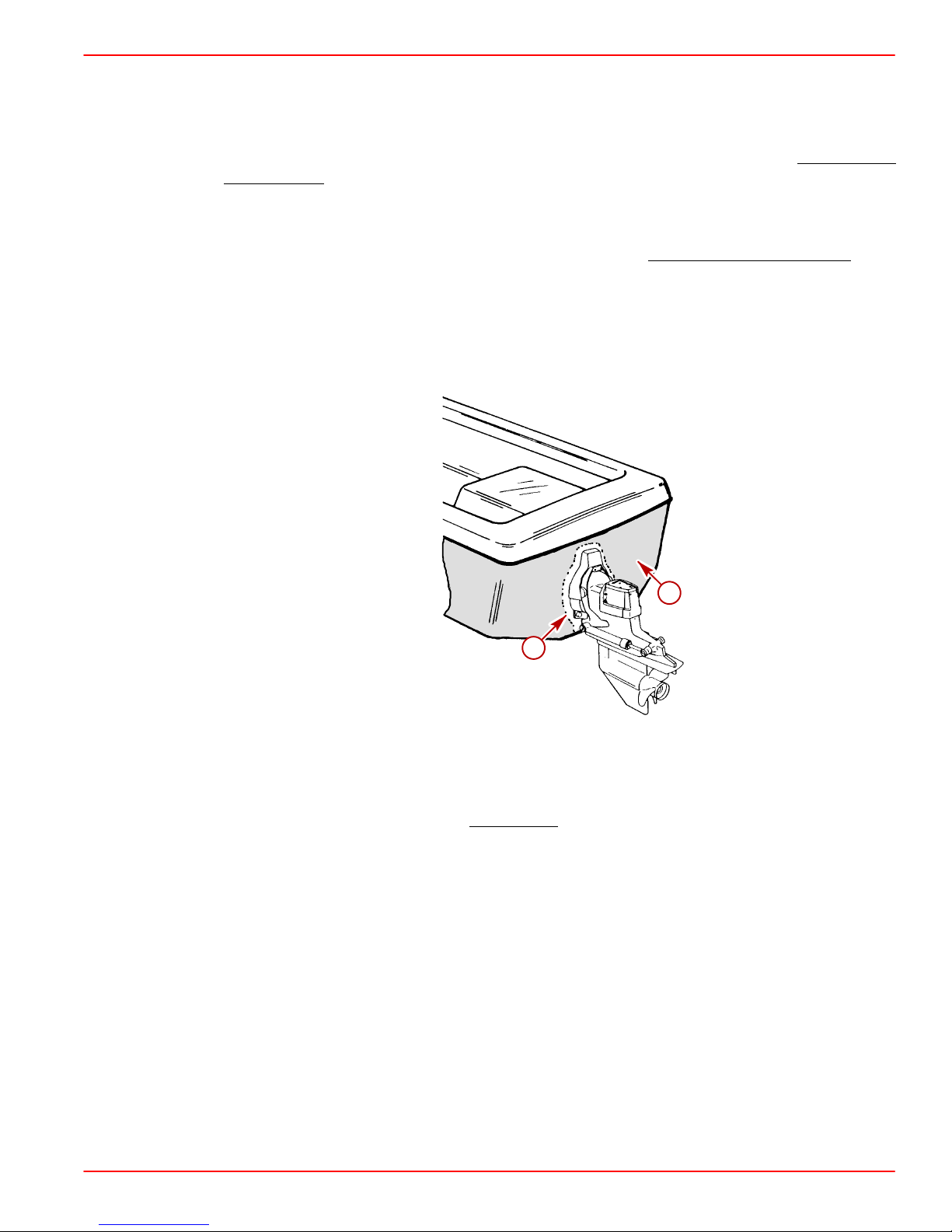
Painting Boat Hull or Boat Transom: Anti-fouling paint may be applied to boat hull and
boat transom but you must observe the following precautions:
IMPORTANT: DO NOT paint anodes or MerCathode System reference electrode and
anode, as this will render them ineffective as galvanic corrosion inhibitors.
GASOLINE ENGINES BRAVO MODELS
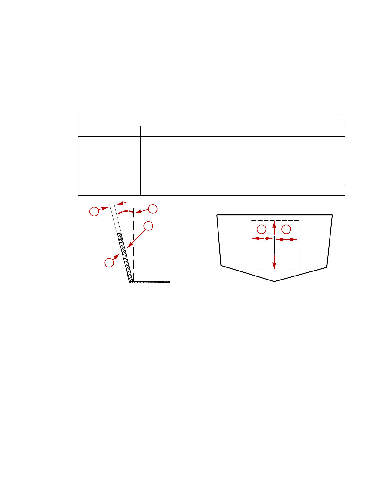
IMPORT ANT: If anti-fouling protection is required for boat hull or boat transom
, copper or tin base paints, if not prohibited by law, can be used. If using copper or tin
based anti-fouling paints, observe the following:
• Avoid an electrical interconnection between the Mercury MerCruiser Product,
Anodic Blocks, or MerCathode System and the paint by allowing a minimum of
1-1/2 in. (40mm) UNPAINTED area on transom of the boat around these items.
a
b
71176
a-Painted Boat Transom
b-Minimum 1 1/2 in (40 mm) UNPAINTED Area Around Transom Assembly
NOTE: Sterndrive unit and transom assembly can be painted with a good quality marine
paint or an anti-fouling paint that DOES NOT
contain copper, tin, or any other material that
could conduct electrical current. Do not paint drain holes, anodes, MerCathode system or
items specified by boat manufacturer.
Page 9 of 116
Page 10
GASOLINE ENGINES BRAVO MODELS
Installation Requirements
Boat Construction
TRANSOM THICKNESS AND SURFACE
IMPORTANT: Transom thickness and surface plane (flatness) must be controlled
where the sterndrive unit mounts.
Transom thickness and surface must conform to the following:
Thickness Between 2 - 2-1/4 in. (51 - 57 mm)
Parallelism Inner and outer surfaces must be parallel within 1/8 in. (3 mm)
Flatness Transom surfaces in area where transom assembly will be
mounted (includes vertical as well as horizontal dimensions):
Inner Surface – Flat within1/8 in. (3 mm)
Outer Surface – Flat within1/16 in. (2 mm)
Angle 10-16 Degrees
Transom Specifications
ENGINE BED
a
e
b
d d
c
22170
a-Transom Thickness
b-Inner Surface
c-Outer Surface
d-Transom Plate Coverage
e-Transom Angle
Engine bed must position engine so that a minimum of 1/4 in. (6mm) up and down
adjustment still exists on mounts after performing final engine alignment. This is necessary
to allow for realigning engine in the future.
72700
NOTE: Although the engine mounts allow some adjustment, it is a good practice to ensure
that the front and rear mount locations in the vessel are in parallel planes. This may be
checked by tying a string from the left front mount location to the right rear mount location
and another from right front to left rear. The strings should touch where they cross
Page 10 of 116
.
Page 11

ENGINE COMPARTMENT
Boating standards (NMMA, ABYC, etc.) and Coast Guard regulations must be adhered to when constructing the engine compartment.
Care must be exercised in the design and construction of the engine compartment. Seams
must be located so that any rain water, which may leak through the seams, is directed away
from the air intake system. Water that runs onto the air intake may enter the engine and
cause serious damage to internal engine parts.
Over the last several years, engine compartments have been designed to be quieter. The
most common material used to deaden the engine sound is some type of insulation material.
Normally, the quieter the engine compartment is, the more insulation material used which
results in less air space inside. The less air space inside the engine compartment, the hotter
the inside air temperature. Attention must be given to the air temperature that is inside this
engine compartment while the engine is running or after a period of time after the engine
is shut off (heat soak). Refer to the following information on Engine Compartment Ventilation.
ENGINE COMPARTMENT VENTILATION
GASOLINE ENGINES BRAVO MODELS
WARNING
General Information
According to Boating standards (NMMA, ABYC, etc.) and Coast Guard regulations the engine compartment ventilation system has multiple tasks. Included are the following:
1. To supply the engine with combustion air.
2. To maintain a low temperature in the engine compartment.
3. To vent the air and fumes in the engine compartment.
Fresh air should enter the engine compartment as low as possible and the heated air should
be discharged from the highest point.
When sufficient ventilation is not provided, too much heat can build-up inside of engine
compartment and cause vapor locking. The engine will not want to restart after it has been
shut of f for a short period of time. If it does restart, the engine will quit when given the throttle
to get the boat up on plane or to pull up a water skier.
For engines utilizing fuels containing alcohol and the newer “reformulated gasolines” (See
OEM Service Bulletin 95-2.) proper ventilation is more critical to prevent vapor locking.
If a separate air shaft (or similar) is used to provide engine compartment ventilation or additional ventilation, care must be taken to prevent seawater and spray from entering it.
Page 11 of 1 16
Page 12

GASOLINE ENGINES BRAVO MODELS
Combustion Air Requirements
Engine compartments with natural draft ventilation must have vent openings of sufficient
size and location to accomplish the tasks previously outlined.
IMPORTANT: The size of ventilation openings must be increased if any auxiliary
equipment is located in the engine compartment.
The combustion air requirement (per engine) for the specified engines at Wide Open
Throttle are given in the chart below:
Combustion Air Requirements (Per Engine) and Ventilation Information
Engine Air
Model
Requirements
at W O T
3.0L
4.3L
4.3LH
4.3L EFI
5.0L
5.0L EFI
5.7L
5.7L EFI
350 Mag MPI
MX6.2L MPI
454 Mag MPI
7.4L MPI
502 Mag MPI
1
: For engine combustion air only - NOT total engine compartment ventilation requirement.
251 ft.3/Min.
(0.118 m
364 ft.3/Min.
(0.172m
3
424 ft.3/Min
(0.200 m
486 ft.3/Min.
(0.229 m
506 ft.3/Min.
(0.239 m
545 ft.3/Min.
(0.257 m
657 ft.3/Min.
(0.310 m
726 ft.3/Min.
(0.342m
3
3
/sec.)
/sec.)
3
/sec.)
3
/sec.)
3
/sec.)
3
/sec.)
3
/sec.)
/sec.)
MINIMUM
Combustion Air Vent
Area Per Engine
1
25 in2 (161 cm2) 2.4 ft.
36 in2 (232 cm2)
42 in2 (271 cm2)
49 in2 (316 cm2)
51 in2 (329 cm2)
2
55 in
(355 cm2)
66 in2 (426 cm2)
73 in2 (471 cm2)
Engine Physical
Volume
3
(68.0 l)
3
4.6 ft.
(130.3 l)
3
5.0 ft.
(141.6 l)
3
5.0 ft.
(141.6 l)
3
5.8 ft.
(164 l)
3
5.8 ft.
( 164 l)
3
6.0 ft.
(170 l)
3
6.0 ft.
(170 l)
Page 12 of 116
IMPORTANT: The amount of vent area required, according to boating standards
(NMMA, ABYC, etc.) and Coast Guard regulations, for complete (total) engine
compartment ventilation must include the engine combustion air vent area plus the
engine compartment ventilation requirements.
The pressure differential between outside and inside the engine compartment must not
exceed the following value.
Maximum Pressure Differential at Wide Open Throttle
2 in. (51 mm) of water (measured with a manometer)
Page 13

GASOLINE ENGINES BRAVO MODELS
Compartment Temperature - Specifications
Air temperatures inside engine compartments have been measured in excess of 200° F (82°
C). The long term effect to fuel system components running at these excessive temperatures is not known at this time.
According to specification SAE J1223 for Marine Carburetors:
“The carburetor shall be capable of operation throughout an ambient (air temperature)
range from +20° to +176° F (–7° to +80° C) without failure.”
Carburetors, throttle body injection (TBI) units and components for multi-port EFI systems
used by Mercury MerCruiser meet this specification.
Under the hottest outside air temperature condition at which the boat will be operated, the
air temperature inside the engine compartment, measured at the flame arrestor, shall not
exceed176° F (80° C). Also, the temperature of the fuel being supplied to the engine shall
not exceed 110° F (43° C) at any location between the fuel tank and the engine’s fuel pump.
Since many factors influence engine compartment temperature, temperature measurements should always be carried out.
Test as follows:
1. The boat being tested shall be a standard production boat fitted as it would be for deliv-
ery to a dealer.
2. T emperature test meter used shall be of the type that can be read without opening the
engine cover.
3. During the test, in Step 4, engine compartments are to remain closed. No outside air is
to be forced into the engine compartment during the test and the bilge blower should not
be running.
4. Engine Running and Heat Soak Test:
a. Use 1 meter and 2 thermo couple. Place one thermo couple at the flame arrestor
to measure the inlet air temperature. Place the second thermo couple at the fuel
pump to measure the inlet fuel temperature. A third thermo couple is needed if the
fuel supply line between the tank and the fuel pump is higher than the fuel pump.
Place the third thermo couple at the highest point of the supply line to measure the
temperature of the fuel at that point.
b. Start engine to warm it up. After engine is at its normal operating temperature, run
engine at 1500 rpm (in neutral gear) for 15 minutes. Record both temperature readings at 5 minute intervals.
c. After 15 minutes running at 1500 rpm, shut engine off and continue to record both
temperature readings at 5 minute intervals for the next 45 minutes.
d. After the 45 minute heat soak test, start engine and idle (in neutral gear) for 20 min-
utes. Continue to record both temperature readings at 5 minute intervals.
IMPORT ANT: If the temperature at either location exceeds specifications, the engine
compartment will need additional ventilation until both temperatures remain below
these specifications.
Page 13 of 116
Page 14
GASOLINE ENGINES BRAVO MODELS
Exhaust System
MEASURING PROCEDURE
1. Fill all fuel, water, gray water and heater tanks to maximum capacity.
NOTE: Weight can be added in these locations to simulate full loaded condition.
2. Add maximum allowable cargo weight to boat in areas where it will be stowed, including
refrigerator and lockers.
3. Add 190 lb (86 kg) of weight in all locations where each passenger will sit during normal
operation.
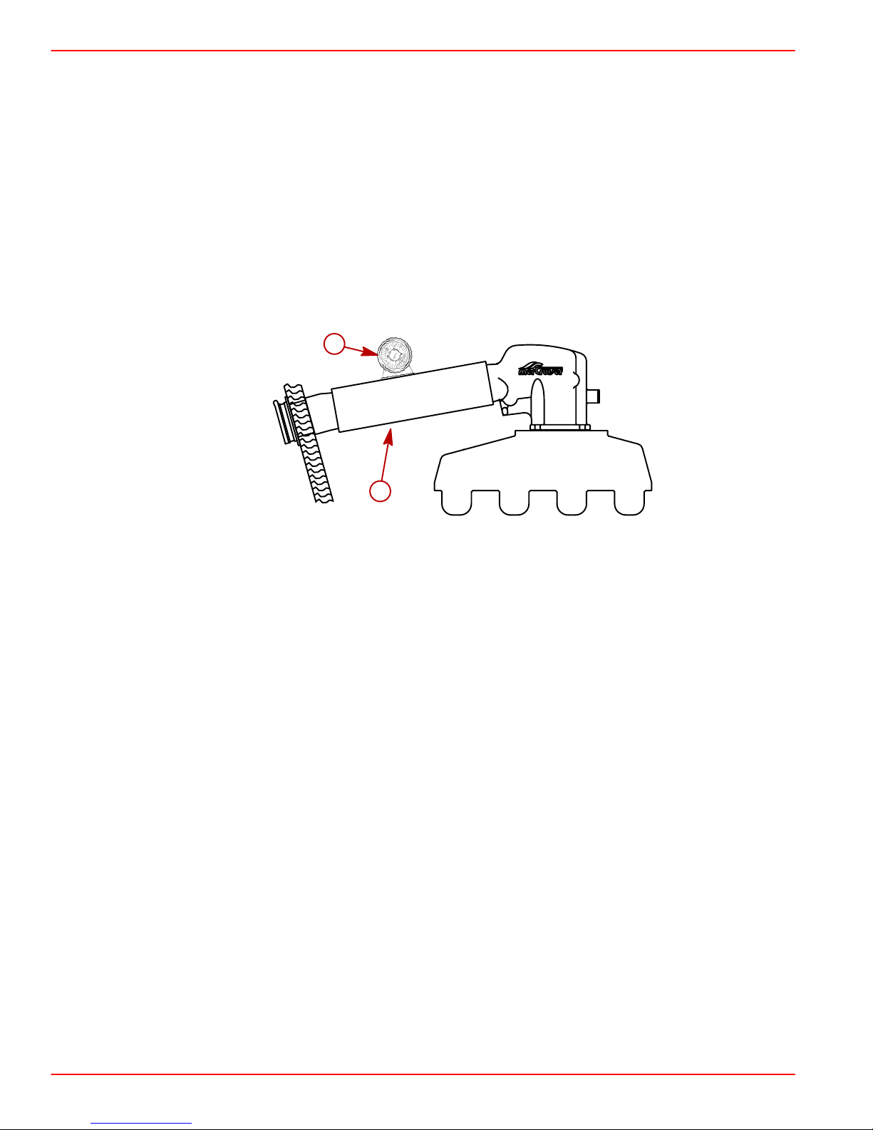
4. Measure exhaust elbow height. Also, measure exhaust system slope on applications
with through the hull or through the transom exhaust.
a
72429
b
Using A Universal Protractor (Inclinometer) To Measure Slope
a-Protractor
b-Exhaust Hose Or Tube
5. Follow instructions a. or b.:
a. On applications with through the propeller exhaust: Proceed to Step 6.
b. On applications with through the hull or through the transom exhaust:
(1.)Move load weight to bow to simulate greatest “bow-down” attitude the boat will
encounter in normal operation.
(2.)Recheck exhaust system slope.
(3.)Proceed to Step 6.
75203
Page 14 of 116
Page 15
GASOLINE ENGINES BRAVO MODELS
6. On all applications:
a. Move load weight and cargo weight to stern of boat to simulate greatest “stern-down”
attitude the boat will encounter such as when loading.
IMPORTANT: Be sure to consider swim platform loading and PWCs.
b. Recheck exhaust system measurements.
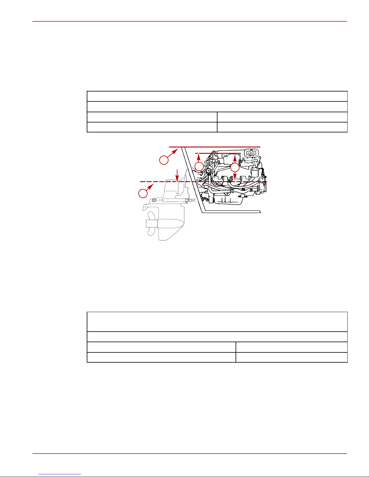
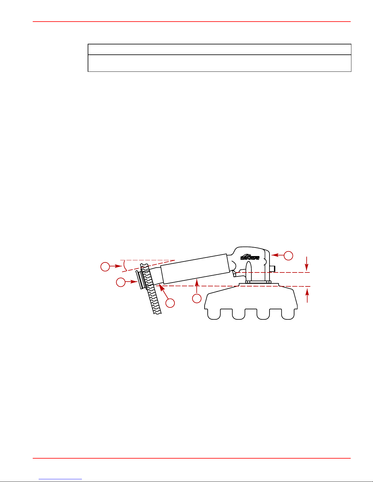
7. Measurements must be equal to or greater than, the following:
On All Applications:
Minimum Exhaust Elbow Height from Top of Elbow to Waterline
Model Measurement
All V6 and V8 13 in. (330 mm)
a
b
c
d
71533
MCM 454/502 MPI Engine Shown (All V-6 and V-8 Engines Similar)
a-Top Of Transom
b-Highest Point On Exhaust Elbow
c-Measurement
d-Waterline
Additional Requirements for Through The Hull and
Through The Transom Exhaust System Applications:
Minimum Continuous Downward Slope (Exhaust Hoses, Collector, Etc.)
Model / Application Measurement
All Sterndrive 6°
Page 15 of 116
Page 16
GASOLINE ENGINES BRAVO MODELS
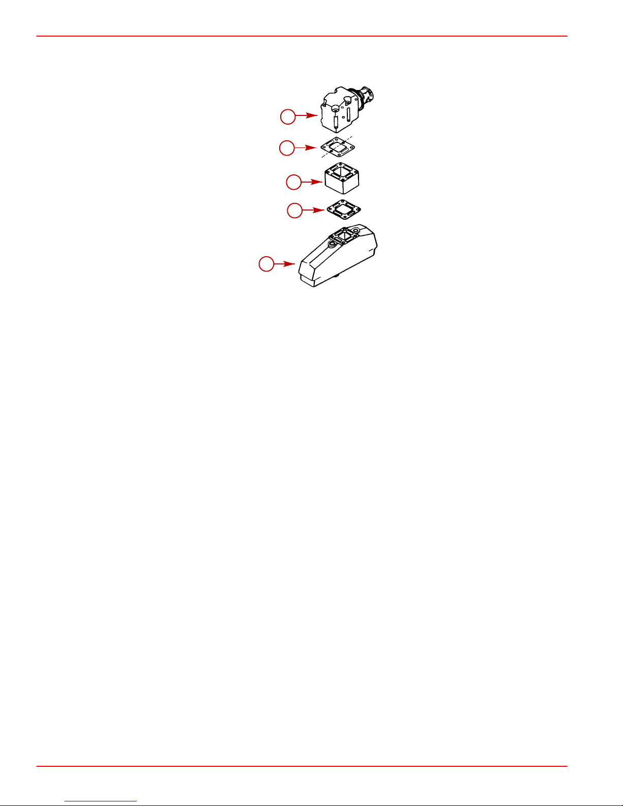
8. If measurements are less than shown in Step 7., exhaust elbow risers must be installed
to achieve proper dimension.
Typical Riser Installation
a-Exhaust Elbow
b-Restrictor Gasket
c-Riser
d-Open Gasket (4 Slots)
e-Exhaust Manifold
a
b
c
d
e
70621
Additional information:
• No risers are available for the V6 engine with Single-Piece Exhaust Manifolds.
• Up to a maximum of 9 in. (229 mm) of riser height can be added, except on those engines
listed previously.
Page 16 of 116
Page 17
THROUGH THE TRANSOM OR HULL EXHAUST
Refer to Exhaust Resonators in this SECTION for additional information on 454 and
502 cid (7.4 L and 8.2 L) engine exhaust requirements.
When designing and installing an exhaust system, in addition to other model specific
requirements, Mercury MerCruiser requires the following to be observed:
• Exhaust fittings (flanges and outlets) must be of proper size to accommodate 4 in.
(102 mm) inner diameter exhaust hoses.
• Exhaust fittings must be equipped with internal water shutters.
• An exhaust flapper must be used over each outlet.
• Exhaust outlet must be slightly above the water line with boat at rest in the water and
a full load aboard.
• Exhaust hoses, collectors and pipes must not be higher than exhaust elbows at any
point.
• The drop in the exhaust system must be continuously sloping so that a low spot does
not exist at any point in the exhaust hose or pipe.
GASOLINE ENGINES BRAVO MODELS
NOTICE
• The exhaust system on Mercury MerCruiser engines must have a minimum of 6°
downward slope between the exhaust elbow outlet and the exhaust outlet of the boat.
• The exhaust system on Mercury MerCruiser engines must have a minimum of 4 in.
(102 mm) of vertical drop between the exhaust elbow outlet and the exhaust outlet
of the boat.
e
a
d
c
Example Of Sterndrive (MCM) Through The Transom or Hull Exhaust Models
a-Minimum Continuous Exhaust System Slope
b-Exhaust Hose
c-Exhaust Fitting
d-Flapper
e-Exhaust Elbow
f-Minimum Exhaust System Vertical Drop
b
75203
• Back pressure must not exceed 2 psi (14 kPa) when measured at exhaust elbow
outlets.
Page 17 of 116
Page 18
GASOLINE ENGINES BRAVO MODELS
EXHAUST RESONATOR
The exhaust resonators (provided with the engine package or available separately) are
designed to provide increased resistance to water ingestion due to the tuning effects of the
exhaust system. Quicksilver resonators are designed to break up the exhaust pulses.
Avoid severe engine damage. Water ingestion by the 454 and 502 cid (7.4L
and 8.2L) engines may occur in some instances without the use of specially
designed exhaust resonators. Install exhaust resonators in the exhaust
system when specified.
IMPORTANT: Exhaust resonators must be installed on 7.4L MPI, 454 Mag MPI and 502
Mag MPI Models of sterndrive engines with through the transom (or through the hull)
exhaust
On 454 and 502 cid (7.4 and 8.2L) sterndrive engines using through the transom or hull
exhaust systems, special care must be exercised in system design and construction to
prevent an adverse tuning effect on engine exhaust output.
Exhaust system tuning can be affected by various factors that are beyond the control of
Mercury MerCruiser. Following are several factors that can affect exhaust system tuning:
• Type and configuration of exhaust outlet.
CAUTION
• Length of exhaust hose.
• Amount of back-pressure in exhaust system.
Exhaust Resonator Kit use on Sterndrive Models:
CAN Be Used With:
1. Transom mounted muffler tips.
2. Waterlift mufflers or other mufflers that
are mounted outboard of exhaust
1. Silent Choice Exhaust System.
2. Below swim platform exhaust.
3. Mufflers that mount between exhaust
elbows.
3. Open exhaust.
CANNOT Be Used With:
elbow and exhaust tip.
Page 18 of 116
Page 19
INSTALLATION
GASOLINE ENGINES BRAVO MODELS
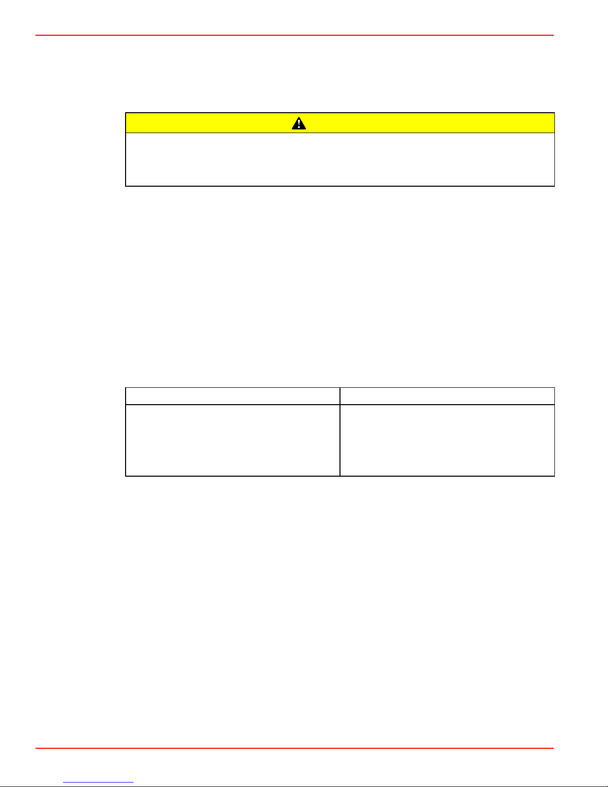
The resonator is installed in exhaust hose with open end toward exhaust elbow. Resonator
is positioned so that inside flat surface is approximately 17 in. (432 mm) from front edge
of exhaust hose, but no closer than 2 in. (51 mm) to exhaust outlet on sterndrive. The
17 in. (432 mm) dimension can be reduced, if necessary, to a minimum of no less than
13 in. (330 mm).
A clamp is then installed and tightened around the hose so that it clamps around center of
resonator. This position is 1 in. (25 mm) less than the position of the resonator as discussed
in the previous paragraph.
g
c
f
b
e
a
d
Through The Transom Exhaust With Resonator
a-Exhaust Resonator
b-Exhaust Hose
c-Dimension To Inside Flat Surface Of Resonator Approximately 17 in. (432 mm),
But No Less Than 13 in. (330 mm)
d-No Less Than 2 in. (51 mm) Between Fitting And Resonator
e-Clamp Position - Around Center Of Resonator
f-Exhaust Fitting
g-Exhaust Elbow
454 AND 502 MAG BRAVO MODEL EXHAUST RECOMMENDATION
IMPORT ANT: T o get maximum performance from Magnum Bravo Models, through the
transom or hull exhaust is required.
NOTE: If noise regulations do not allow the use of through the transom or hull exhaust, an
exhaust pipe kit (Quicksilver Part Number 44266A6) must be installed for through the prop
exhaust. This kit also contains an exhaust tube that is used in place of the exhaust bellows.
IMPORTANT: It is recommended that the exhaust bellows on the transom assembly
be removed. This is necessary to avoid creating a vacuum at the exhaust outlet in the
propeller at higher boat speeds. This vacuum could degrade propeller performance
on some boats.
75203
Page 19 of 116
Page 20

GASOLINE ENGINES BRAVO MODELS
Fuel Delivery System
Boating standards (NMMA, ABYC, etc.) and Coast Guard regulations must be adhered to when constructing the engine compartment.
GENERAL
The main concern of a boat’s fuel system is safety; this must be achieved through a technically sound installation and constant inspection.
The fuel system, from the filler pipe to the fuel pump, is the same in principle for all boats.
The fuel tank is an integrated component of the boat. Refer to the special information on
service and maintenance, which you have received from the tank manufacturer.
Only a few points related to function and safety are listed here [Refer to boating standards
(NMMA, ABYC, etc.) and Coast Guard regulations for complete guidelines]:
• All connections should be on the upper side of the tank.
• The drain plug at the lowest point on the tank serves to permit the removal of water and
sediment.
• The filler pipe outer diameter should be at least 2 in. (50 mm).
WARNING
• The tank breather pipe must have an inner diameter of at least 1/2 in. (13 mm) and must
be fitted with a swan neck to prevent water from entering the tank.
It is recommended that the exact route and length of the fuel lines be established at the first
installation of the engine to prevent problems later in connecting them to the engine.
All fuel lines must be well secured. The holes where the lines run through the bulkheads
should be carefully rounded off or protected with rubber grommets. This prevents damage
to the lines from abrasion.
The following, but not limited to the following, additional fuel connection related points, ap-
plying to all engines unless otherwise stated, must be considered [Refer to boating standards (NMMA, ABYC, etc.) and Coast Guard regulations for complete guidelines]:
1. On Gasoline Engines: Fuel tank should be mounted below carburetor level (if possible)
or gravity feed may cause carburetor fuel inlet needle to unseat and flooding may result.
2. Fuel pickup should be at least 1 in. (25 mm) from the bottom of fuel tank to prevent picking up impurities.
3. On Gasoline Engines: The maximum measured vacuum at the engine’s fuel inlet must
not exceed 2 in. Hg or 1 psi (6.9 kPa) at 600, 3000, full throttle rpm, and idle rpm.
IMPORTANT: Vacuum reading higher than specified can cause vapor locking with
some of today’s fuels. It can also cause poor engine performance because of fuel
starvation.
4. On Gasoline Engines: Fuel lines used must be Coast Guard approved (USCG Type
A1).
Diameter of fittings and lines must not be smaller than 5/16 in. (8 mm) ID on 262 CID/4.3L
and 305 CID/5.0L and 350 CID/5.7L engines.
Diameter of fittings and lines must not be smaller than 3/8 in. (10 mm) I.D. on 377 CID/6.2L,
454 CID/7.4L and 502 CID/8.2L engines.
5. On Multi-Engine Gasoline Installations: It is best to use a fuel pickup and supply line
for each engine. If a single pickup and line is used, line must not be smaller than 1/2 in.
(13mm) I.D.
Page 20 of 116
Page 21
6. Larger diameter (than previously specified) lines and fittings must be used on installa-
tions requiring long lines or numerous fittings.
7. Fuel line(s) should be installed free of stress and firmly secured to prevent vibration and/
or chafing.
8. Sharp bends in fuel lines should be avoided.
9. A flexible fuel line must be used to connect fuel supply line to fuel inlet fitting on engine
to absorb deflection when engine is running.
SPECIAL INFORMATION ABOUT ELECTRIC FUEL PUMPS
The electric fuel pump and factory installed water separating fuel filter have been
carefully designed to function properly together . Do not install additional fuel filters
and/or water separating fuel filters between fuel tank and engine.
The installation of additional filters may cause:
• Fuel Vapor Locking
• Difficult Warm-Starting
• Piston Detonation Due to Lean Fuel Mixture
GASOLINE ENGINES BRAVO MODELS
CAUTION
• Poor Driveability
SPECIAL INFORMATION FOR ALL GASOLINE ENGINES
Avoid gasoline fire or explosion. Gasoline is extremely flammable and highly explosive under certain conditions. NEVER use gasoline as a cleaning solvent.
IMPORTANT: The following information is provided to ensure proper installation of
brass fittings or plugs installed into fuel pump or fuel filter base:
• Use #592 Loctite Pipe Sealant with Teflon on threads of brass fittings or plugs. DO
NOT USE TEFLON TAPE.
• Brass fittings or plugs should first be threaded into fuel pump or fuel filter base
until finger tight.
• Fittings or plugs should then be tighten an additional 1-3/4 to 2-1/4 turns using
a wrench. DO NOT OVERTIGHTEN.
• To prevent over-tightening when installing a fuel line, the brass fittings should be
held with a suitable wrench as fuel line connectors are tightened securely.
WARNING
Page 21 of 116
Page 22

GASOLINE ENGINES BRAVO MODELS
Battery
IMPORTANT: Boating industry standards (BIA, ABYC, etc.), federal standards and
Coast Guard regulations must be adhered to when installing battery. Be sure battery
cable installation meets the pull test requirements and that positive battery terminal
is properly insulated in accordance with regulations.
IMPORT ANT: It is recommended (required in some states) that battery be installed in
an enclosed case. Refer to regulations for your area.
IMPORTANT: Engine electrical system is negative (–) ground.
Select a battery that meets all of the following specifications:
• 12-volt marine type.
• Tapered post connectors or side terminal connectors.
IMPORTANT: Do NOT use a battery with wing nut connectors.
• Battery capacity rating of at least:
Gasoline Engines
BATTERY CABLES
Select proper size positive (+) and negative (–) battery cables, using chart. Battery should
be located as close to engine as possible.
IMPORTANT: Terminals must be soldered to cable ends to ensure good electrical
contact. Use electrical grade (resin flux) solder only. Do not use acid flux solder as
it may cause corrosion and a subsequent failure.
Engine
(Cyl./Type)
cid (l) Minimum Required Cranking Battery Size
V6 EFI 262 (4.3) 550 cca/700 mca/120 Ah
V6 Carb
V8 Carb
V8 Carb
V8 EFI
V8 MPI
V8 MPI
V8 MPI
262 (4.3)
305 (5.0)
350 (5.7)
305 (5.0)
350 (5.7)
377 (6.2)
454 (7.4)
375 cca/475 mca/90 Ah
550 cca/700 mca/120 Ah
650 cca/825 mca/150 Ah
502 (8.2)
Gasoline Engines
Up to 3-1/2 ft. (1.1m) 4 (25mm2)
3-1/2 - 6 ft. (1.1-1.8m) 2 (35mm2)
6 - 7-1/2 ft. (1.8-2.3m) 1 (50mm2)
7-1/2 - 9-1/2 ft. (2.3-2.9m) 0 (50mm2)
9-1/2 - 12 ft. (2.9-3.7m) 00 (70mm2)
12 - 15 ft. (3.7-4.6m) 000 (95mm2)
15 - 19 ft. (4.6-5.8m) 0000 (120mm2)
Page 22 of 116
Cable Length
Cable Gauge
Page 23

MULTIPLE EFI ENGINE BATTERY PRECAUTIONS
Situation
Alternators: Alternators are designed to charge the battery that supplies electrical power
to the engine that the alternator is mounted on. When batteries for two different engines are
connected, one alternator will supply all of the charging current for both batteries. Normally,
the other engine’s alternator will not be required to supply any charging current.
EFI Electronic Control Module (ECM): The ECM requires a stable voltage source. During
multiple engine operation, an onboard electrical device may cause a sudden drain of voltage
at the engine’s battery. The voltage may go below the ECM’s minimum required voltage.
Also, the alternator on the other engine may now start charging. This could cause a voltage
spike in the engine’s electrical system.
In either case, the ECM could shut off. When the voltage returns to the range that the ECM
requires, the ECM will reset itself. The engine will now run normally. This ECM shut down
usually happens so fast that the engine just appears to have an ignition miss.
Recommendations
Batteries: Boats with multi-engine EFI power packages require each engine be connected
to its own battery. This ensures that the engine’s Electronic Control Module (ECM) has a
stable voltage source.
GASOLINE ENGINES BRAVO MODELS
Battery Switches: Battery switches should always be positioned so each engine is running
off its own battery . DO NOT operate engines with switches in BOTH or ALL position. In an
emergency, another engine’s battery can be used to start an engine with a dead battery.
Battery Isolators: Isolators can be used to charge an auxiliary battery used for powering
accessories in the boat. They should not be used to charge the battery of another engine
in the boat unless the type of isolator is specifically designed for this purpose.
NOTE: Sure Power Industries Inc., Model 32023A meets this design specification.
1. The boat may have 2 engines connected to a single Model 32023A battery isolator.
2. The Model 32023A battery isolator is connected to 2 banks of batteries.
3. Each bank contains 2 batteries with the cranking battery for 1 engine in each bank.
4. The second battery in each bank is connected in parallel to the cranking battery.
5. The Model 32023A battery isolator is designed for this type of use; 2 battery banks, 2
charging sources, 120 amps (maximum alternator output).
6. When the engines are running, either engine’s alternator could be charging either bank
of batteries through the Model 32023A battery isolator.
Any other manufacturer’s battery isolator that is the same type as the Sure Power Inc.,
Model 32023A could also be used.
Generators: The generator’s battery should be considered another engine’s battery.
Page 23 of 116
Page 24

GASOLINE ENGINES BRAVO MODELS
EFI Electrical System Precautions
NOTE: All references to EFI models apply to all EFI and MPI engines.
Avoid damage to the EFI electrical system components: Refer to the following precautions when working on or around the EFI electrical harness, or when adding other electrical accessories:
• DO NOT tap accessories into engine harness.
• DO NOT puncture wires for testing (Probing).
• DO NOT reverse battery leads.
• DO NOT splice wires into harness.
• DO NOT attempt diagnostics without proper, approved Service Tools.
Instrumentation
We recommend the use of Quicksilver Instrumentation and Wiring Harnesses which have
been specifically designed for compatibility with our engines, and to the same high quality
and performance standards. Refer to Mercury Precision Parts / Quicksilver Accessories
Guide for selection.
CAUTION
GAUGES
Refer to Instrumentation Wiring Diagrams for specific wiring diagrams.
ABYC standards recommend a group of four gauges.
The basic four gauges that must be used with the engine are:
1. Tachometer
2. Oil Pressure
3. Water Temperature
4. Voltmeter
Page 24 of 116
Page 25

HARNESSES
GASOLINE ENGINES BRAVO MODELS
CAUTION
If Quicksilver wiring harness is used and a fused accessory panel is to be installed
(40-amp current draw maximum), be sure to connect it as shown in the wiring diagrams. Do not connect accessory panel at any other location, as wires in wiring harness may not be of sufficient size to handle current load.
Instrumentation wiring extension harnesses that can be routed from instruments to engine
are available in several lengths. Refer to Mercury Precision Parts / Quicksilver Accessories
Guide.
When designing the craft and harness wiring, consider the following:
• Ensure that the harnesses will not be rubbed or pinched.
• Avoid routing the harness in areas where it could be damaged or short circuited later
in the assembly process, such as when a screw is inserted, or a hole is drilled.
IMPORTANT: Harness receptacles can be damaged by overtightened clamps.
• If an extension harness is required, be certain to secure connection properly. All cannon
plug style electrical connectors, including the one at the engine, should be secured with
a hose clamp to avoid a loose connection or water entry.
• It is an ABYC recommendation that harnesses be fastened to boat at least every 18 in.
(460 mm).
Power Trim Control
Any of the Quicksilver panel or in-handle type trim controls (that are specified for use with
Mercury MerCruiser sterndrives) can be used with this Power Trim system. Install trim control in accordance with instructions that accompany it.
Power Trim Pump Location
Select an appropriate mounting location for the trim pump that meets the following requirements:
• Within length limits of black and gray hydraulic hoses coming from gimbal housing
assembly.
• Close to the battery so that trim pump battery leads can be connected.
• Allow easy access to trim pump oil fill and vent locations.
• Area where pump will not be exposed to water.
• Trim pump must be mounted so that when steering wheel is turned in either direction
(right or left), the power steering booster cylinder does not come in contact with trim
pump.
• Pump can be mounted on floor or transom.
Page 25 of 116
Page 26

GASOLINE ENGINES BRAVO MODELS
Propeller Selection
GENERAL INFORMATION
IMPORTANT: Installed propeller must allow engine to run at its specified maximum
wide-open-throttle revolutions per minute (rpm). Use an accurate service tachometer
to verify engine operating rpm.
It is the responsibility of the boat manufacturer and/or the selling dealer to equip the power
package with the correct propeller(s). Specified engine wide-open-throttle (WOT) and operating rpm range are listed in the “Operation, Maintenance and Warranty Manual” attached
to the engine.
Select a propeller that will allow the engine power package to operate at or near the top end
of the recommended wide-open-throttle operating rpm range with a normal load. High rpm,
caused by an excessive trim angle, should not be used in determining correct propeller
selection.
There is a change in rpm between propeller pitches that is generalized in the following chart:
MCM Models
Pitch Change RPM Change
Gasoline 2 in. 150-200
If full throttle operation is below the recommended range, the propeller must be changed
to prevent loss of performance and possible engine damage. On the other hand, operating
an engine above the recommended operating rpm range will cause higher than normal wear
and/or damage.
After initial propeller selection, the following common problems may require that the propeller be changed to a lower pitch:
• Warmer weather and greater humidity cause an rpm loss.
• Operating in a higher elevation causes an rpm loss.
• Operating with increased load (additional passengers, pulling skiers, etc.)
For better acceleration, such as is needed for water skiing, use the next lower pitch propeller. However , do not operate at full throttle when using the lower pitch propeller but not pulling skiers.
Because of the many variables of boat design, only testing will determine the best propeller
for a particular application. Available propellers are listed in the “Quicksilver Accessories
Guide.”
See “BOAT-IN-THE-WATER TESTS, Maximum rpm Test” in the power package Installation
Manual.
Page 26 of 116
Page 27

RPM REV-LIMITER
GASOLINE ENGINES BRAVO MODELS
IMPORTANT: When selecting a propeller consider this additional information, if applicable:
The engines listed in the following chart are equipped with a rpm rev-limiter that is
set to an upper (or limited) rpm amount. This limit is slightly above the normal operating range of the engine and is designed to help prevent damage from excessive engine rpm. Once the rpm drop into the recommended operating rpm range normal engine operation resumes.
Engine Rev-Limiter
Model
Engine Recommended Operating
RPM Range
4.3L
4.3LH
4.3L EFI
5.0L
4400-4800 4950
5.0L EFI
5.7L
5.7L EFI
MX 6.2L MPI 4800-5200 5350
7.4L MPI 4200-4600 4680
350 Mag MPI
454 Mag MPI
4600-5000 5080
502 Mag MPI
Hot Water Heater Installation Recommendation
IMPORTANT: When connecting a cabin heater or hot water heater, certain requirements must be met:
Rev-Limit RPM Setting
• Supply hose (from engine to heater) and return hose (from heater to engine)
MUST NOT EXCEED 5/8 in. (16 mm) I.D. (inside diameter).
• Make heater connections ONLY at locations indicated in the following informa-
tion.
• Refer to manufacturers’ instructions for complete installation information and
procedures.
• Do not reposition engine temperature switch; it must remain where installed by
factory.
Avoid a performance loss and/or possible engine damage. Engine coolant must
flow continuously from the engine intake manifold to the engine water circulating
pump. NEVER close-off or block the coolant flow to or from a heater.
All heater installations must be plumbed in series with the supply and return connections.
CAUTION
Page 27 of 116
Page 28
GASOLINE ENGINES BRAVO MODELS
Avoid engine overheating which could result in engine damage. On models
equipped with Closed Cooling, an air pocket may form in the closed cooling system
if some coolant is lost from the system and the cabin heater or hot water is mounted
higher than the fill cap on the heat exchanger. Heater must be mounted lower
the fill cap of the heat exchanger on models so equipped.
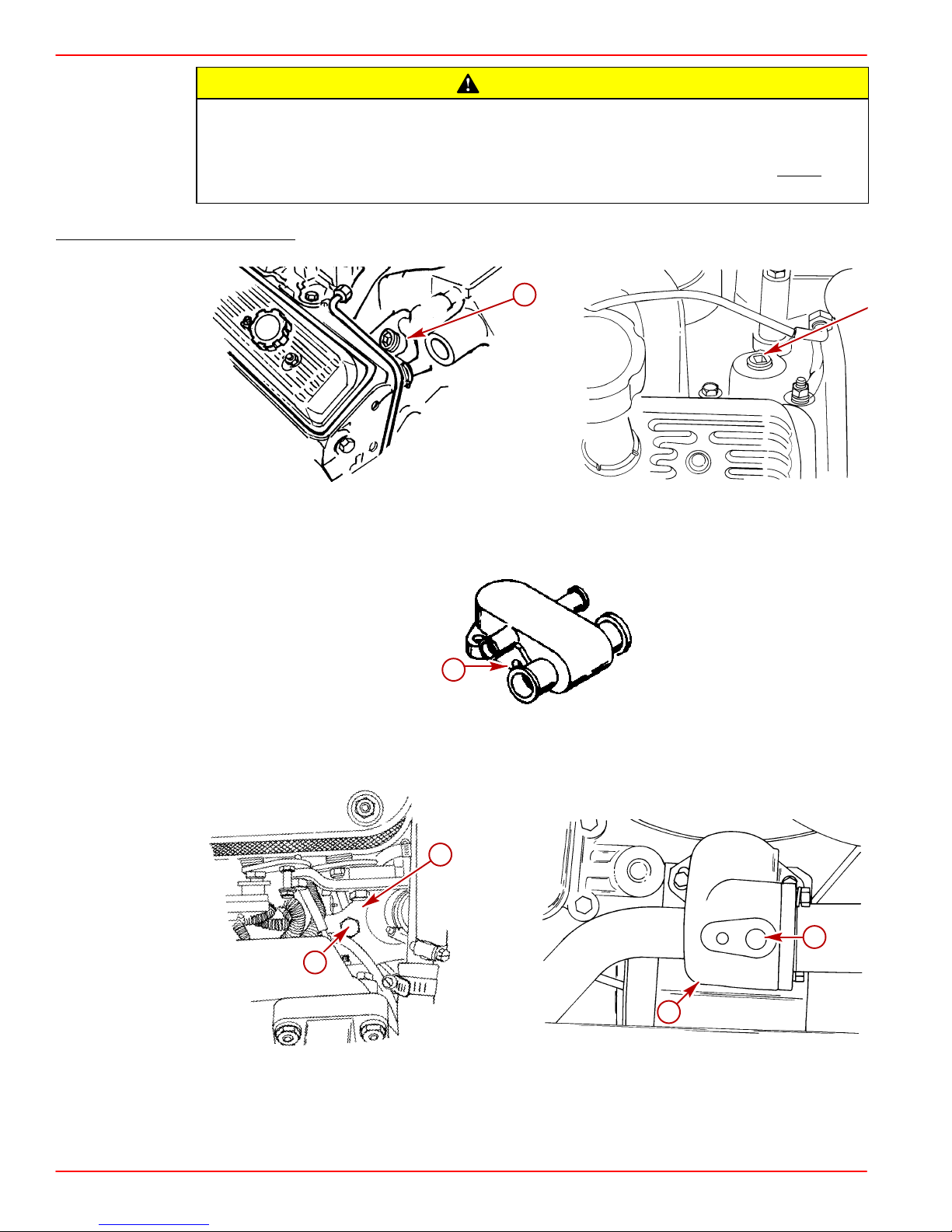
SUPPLY HOSE CONNECTION
CAUTION
than
a
75473
Seawater Cooling - If Location Is Available
a-Location For Hot Water Supply
a
71758
Seawater Cooling - Alternate Location
a-Location For Hot Water Supply (Install Bayonet Fitting Here)
b
74973
a
Closed Cooling Models - If Location Is Available
a-Location for Hot Water Supply (Bayonet Fitting Replaces Brass Plug)
b-Thermostat Housing
Page 28 of 116
a
b
74639
Page 29
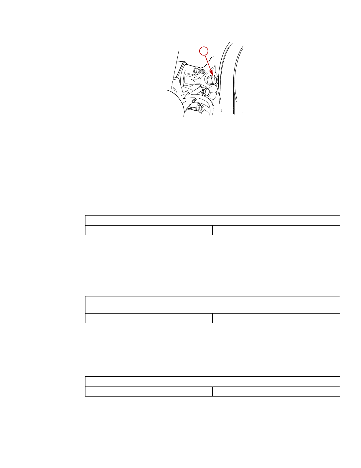
RETURN HOSE CONNECTION
Seawater or Closed Cooling System
a-Location For Hot Water Return
Seawater Connections - General Information
SEA WATER PICKUP HOSE
Seawater inlet hose connections must be made with wire reinforced hose of adequate wall
thickness to prevent it from collapsing from pump suction. Be sure to secure hose connections with hose clamps. Secure hose to prevent contact with any moving parts of the engine.
Select the proper hose from the following chart:
GASOLINE ENGINES BRAVO MODELS
a
75480
Gasoline Engines 1-1/4 in. (32 mm)
SEACOCK SIZE
Seacock used must have an internal cross-sectional area equal to or greater than seawater
inlet hose to prevent restricting water flow . Install valve in an area where it will be easily accessible and supported adequately to prevent hose fatigue. A brass ball or gate valve is required. Select a proper seacock based on the following chart:
Gasoline Engines 1-1/4 in. (32 mm)
SEAWATER STRAINER
Strainer used must be of sufficient size to ensure that an adequate supply of water will be
maintained for cooling the engine. Select a proper seawater strainer based on the following
chart:
Seawater Pickup Hose Inner Diameter
Seacock Size
(Internal Cross-Sectional Area Equal to or Greater Than Size Shown)
Seawater Strainer Minimum Flow Rate
1
Gasoline Engines 30 (114)
1
Amounts listed are in gallons per minute and (liters per minute).
Install seawater strainer in an area where it will be easily accessible for inspection and
cleaning. Strainer should be installed in water inlet hose after the seacock (water inlet valve)
to allow operator to shut off water when cleaning strainer.
Page 29 of 116
Page 30
GASOLINE ENGINES BRAVO MODELS
Throttle/Shift Remote Control and Cables
To ensure proper shift and throttle operation, we recommend the use of a Quicksilver remote
control and cables. Refer to “Quicksilver Accessories Guide” for selection. However, if a
control other than Quicksilver is to be used, control must provide a shift cable travel (at the
shift plate end) of 2-7/8 in. (73 mm) to 3-1/8 in. (80 mm) with a 15-20 lb. (6.8-9 kg) load
applied to the cable end guide.
Steering Helm and Cable
Transom assembly is shipped with the steering cable guide tube preset for cables with end
dimensions that comply with ABYC standards as outlined in the NMMA certification handbook. The steering cable coupler nut must also have a means of locking it to the guide tube
as specified in ABYC requirements.
Failure to use a steering cable locking device could cause loss of steering, which
could cause damage to the boat and/or injury.
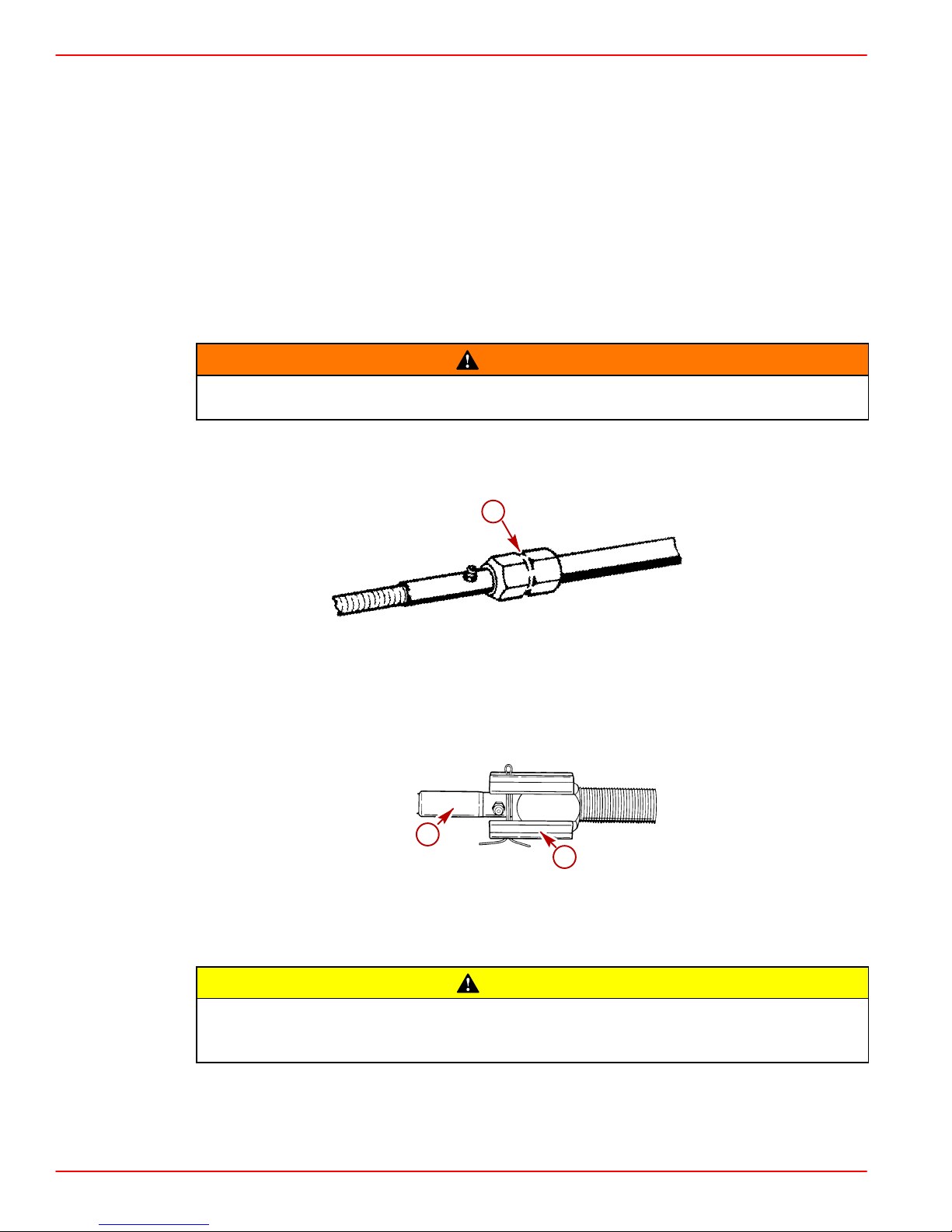
NOTE: All current production Quicksilver Ride Guide steering cables have a self-locking
coupler nut and do not require an external locking device. (Other cable manufacturers also
make cables with self-locking coupler nut.)
WARNING
a
22060
a-Quicksilver Ride Guide Steering Cable Self-Locking Coupler Nut (Identified by
Groove)
IMPORTANT: If using a steering cable that does not have a self-locking coupler nut,
an external locking device must be used.
a
b
Example Of External Locking Device
a-Steering Cable
b-Locking Sleeve
POWER STEERING EQUIPPED UNITS ONLY: If steering cable with improper dimensions is installed, severe damage to transom assembly and/or steering system may
result.
1. Steering cable must be the correct length, particularly when installed in larger boats.
2. Avoid sharp bends, kinks or loops in cable.
3. Fully extended steering cable end dimension must be as shown.
Page 30 of 116
CAUTION
Page 31

STEERING CABLE SPECIFICATIONS
IMPORTANT: Power steering pump lugging (squealing) in a hard right turn (against
lock) may mean a steering cable has been installed that does not have the correct
dimensions.
GASOLINE ENGINES BRAVO MODELS
a
c
b
e
f
k
j
l
a-Coupler Nut - 7/8 - 14 UNF - 28 Thread
b-11-3/4 in. (298 mm) Min.
c-Interface Point
d-1/2 in. (12.7 mm) Max.
e-27/64 in. (10.7 mm) Min. Flat
f-7/64 in. (3.1 mm) Min. Radius
g-5/8 in. (15.9 mm) Max. Diameter End Fitting
h-3/8 in. (9.5 mm)
i-3/8 in. (9.8 mm) Diameter Through Hole (Chamfered Each Side)
j-1-3/8 in. (34.9 mm) Max.
k-5/8 in. (15.9 mm) Diameter Tube
l-Cable Travel:
Mid-Travel Position - 16-7/8 in. (429 mm)
Total Travel To Be 8 in. (203 mm) Min. to 9 in (228 mm) Max.
Travel Each Side of Mid-Travel Position - 4 in. (102 mm ) Min.,
4-1/2 in. (114 mm) Max.
d
g
C
L
h
i
21435
Page 31 of 116
Page 32

GASOLINE ENGINES BRAVO MODELS
Transom Cutout
Before Starting Installation Read “General Information” and “Installation Require-
ments” Sections Completely.
IMPORTANT: The following instructions will provide a sterndrive unit mounting location that is suitable for most boats. Best mounting location for a particular boat, however, can be determined only by testing.
NOTICE to INSTALLER
1. Below 25 m.p.h. (40 km/h):
2. Heavy Duty Applications:
3. Above 25 m.p.h. (40 km/h):
4. Above 50 m.p.h. (80 km/h):
Subtract 1/2 in. (13mm) from “X” Dimension shown.
Subtract 1 in. (25mm) from “X” Dimension shown.
Use “X” Dimension shown.
The “X” Dimension can be increased to improve performance in some applications, but pulling power (for skiing) will decrease. During testing,
the “X” Dimension should be increased 1/2 in. (13mm) at a time until desired performance is achieved but in no case should it ever be increased by more than:
Maximum Increase In “X” Dimension
One
Bravo
Two
3 in. (76 mm) maximum
Bravo Three 1 in. (25 mm) maximum
In ALL sterndrive applications, extreme care should be taken when raising sterndrive unit
to ensure that water supply does not become aerated. Use clear water inlet hose to monitor
incoming water and monitor engine temperature gauge to ensure engine does not overheat.
In applications where cooling water to the engine is supplied by a through the hull
or through the transom fitting, the sterndrive height will not cause cooling water aeration.
IMPORTANT: Damage to Mercury MerCruiser products caused by too high of an
installed height will not be covered by Mercury MerCruiser warranty.
Page 32 of 116
Page 33

Finding Crankshaft Vertical Centerline
SINGLE ENGINE
Locate and mark vertical centerline on transom.
a-Vertical Centerline
DUAL ENGINE
1. Locate and mark boat vertical centerline “a” on transom.
GASOLINE ENGINES BRAVO MODELS
a
71620
a
a-Vertical Centerline
2. Locate and mark crankshaft vertical centerlines “a” on transom.
b
a a
c
c
a-Draw Crankshaft Vertical Centerline Through Desired Mounting Locations
b-Minimum Distance between Crankshaft Vertical Centerlines
c-Crankshaft Vertical Centerlines Must Be an Equal Distance from Boat Vertical
Centerline
71620
22033
V8 (5.0L, 5.7L and 6.2L) 33 (838)
Minimum Distance Between Crankshaft
Vertical Centerlines (Dual Side-By-Side) Chart
Model Measurement [ in. (mm) ]
V6 (4.3L) 33 (838)
V8 (7.4L) 36-1/2 (927)
Page 33 of 116
Page 34

GASOLINE ENGINES BRAVO MODELS
Finding Crankshaft Horizontal Centerline (“X” Dimension)
“X” Dimension can be measured by the “90° Tool Method” or by the “Tape Measure Method.”
90
° TOOL METHOD
1. Construct 90° tool.
a
90°
b
71621
a-Dimension From Chart Below
b-Measurement: 4 Ft. (1.2 M)
To Lower Sterndrive Unit - Subtract from dimension “a.”
To Raise Sterndrive Unit - Add
° TOOL VERTICAL DIMENSION CHART
90
Sterndrive Unit Location
Bravo One/Two/Three 13-9/16 in. (345 mm)
IMPORTANT: This dimension should only be raised or lowered after proper testing.
2. Determine “X” Dimension location of crankshaft centerline(s).
to dimension “a.”
b
c
Single Engine Dual Engine
a-Place 90
b-Point At Which Top Of Tool Contacts Transom On Vertical Centerline Is Crank-
shaft Horizontal Centerline
c-Draw A Line Perpendicular To Vertical Centerline At Crankshaft Horizontal
Centerline
Page 34 of 116
c
a
71622
° Tool Along Boat Bottom At Vertical Centerline
b
a
71623
Page 35

TAPE MEASURE METHOD
Transom angle must be known, then measure “X” Dimension with tape measure.
1. Determine “X” Dimension from the following chart.
Tape Measure Method Charts
GASOLINE ENGINES BRAVO MODELS
Model
Bravo One / Two / Three
Transom Angle This dimension should only be raised or lowered after proper
testing.
16°
15°
14°
13°
12°
11°
10°
14-5/16 in. (364 mm)
14-1/4 in. (362 mm)
14-3/16 in. (360 mm)
14-1/8 in. (359 mm)
14-1/16 in. (357 mm)
14 in. (356 mm)
13-15/16 (354 mm)
2. Measure and layout horizontal centerlines as shown.
b
b
c
c
d
a
d
a
71622
71623
Single Engine Dual Engine
a-“x” Dimension (From Chart) That Corresponds To Transom Angle - Measure Up
From Boat Bottom With Tape Measure
b-Crankshaft Horizontal Centerline
c-Vertical Centerline
d-Draw A Line Perpendicular To Vertical Centerline At Crankshaft Horizontal
Centerline
Page 35 of 116
Page 36

GASOLINE ENGINES BRAVO MODELS
Cutting Transom
Transom cutout can be made by either using the Template [shipped with transom assembly]
or the Transom Drilling Fixture Kit (purchased separately).
Follow instructions indicated on template or provided with drilling fixture.
IMPORTANT:
w Be certain that centerlines on either the template or transom drilling fixture align
with lines previously marked on transom.
w Be sure to drill 1/4 in. pilot holes (for hole saw guide) at a 605 angle and to cut on
the line when making transom cutout. If cutout is made incorrectly, sterndrive unit
steering lever may contact transom, thus limiting steering travel.
w Seal inside edge of transom cutout opening with a suitable sealant to prevent wa-
ter absorption and deterioration of transom.
Transom Cutout Template
90-79135--3
50017
22056
Transom Drilling Fixture Kit
Page 36 of 116
Page 37

Checking Transom Thickness
Ensure transom surface thickness and flatness conform to minimums specified in “Installa-
tion Requirements” listed previously.
a
b
GASOLINE ENGINES BRAVO MODELS
c
a-Measuring Thickness
b-Measuring Flatness
c-Suitable Mandrel To Check For Uniform Transom Thickness
NOTE: Transom must be between 2 in. (51 mm) and 2-1/4 in. (57 mm) a distance of
8” (203 mm) to either side of the vertical centerline.
Installing Transom Assembly
Installing Gimbal Housing
1. Carefully remove transom assembly from shipping carton.
2. Remove and read all tags which are attached to transom assembly.
IMPORTANT: When installing through the transom exhaust
the exhaust bellows on the transom assembly be removed. This is necessary to avoid
creating a vacuum at the exhaust outlet in the propeller at higher boat speeds. This
vacuum could degrade propeller performance on some boats.
3. If required, remove and discard clamps and bellows from gimbal housing.
IMPORTANT: When installing through the propeller exhaust
70004
75479
, it is recommended that
:
• With Bravo One and Bravo Two Sterndrives an exhaust tube MAY BE INSTALLED
for a slight increase in performance.
• With most Bravo Three Sterndrive Models an exhaust tube MAY BE INSTALLED
for a slight increase in performance. On the following Bravo Three Models, the
exhaust bellows must be removed and an exhaust tube MUST BE INSTALLED:
w MCM 7.4L MPI
w MCM 454 Mag MPI
w MCM 502 Mag MPI
Page 37 of 116
Page 38

GASOLINE ENGINES BRAVO MODELS
• With a Silent Choice Exhaust System the exhaust bellows must be removed and
an exhaust tube MUST BE INSTALLED.
• With any application, installation of an exhaust tube will increase exhaust noise.
NOTE: Exhaust tube parts are provided with a Bravo Three Sterndrive. They are located
in the sterndrive unit box.
4. If required, install exhaust tube on gimbal housing as follows:
a. Remove and discard clamps and exhaust bellows.
Exhaust tube clamp may corrode if grounding clip is not installed.
b. Install grounding clip on tube.
NOTE: Bellows adhesive is not used when installing an exhaust tube.
c. Position tube so that “SIDE” markings on tube are facing toward the right and left
sides.
d. Install clamp.
e. Tighten clamp. Torque to 35 lb-in. (4 Nm).
CAUTION
d
a-Exhaust Tube
b-Clamp
c-“SIDE” Marking
d-Exhaust Tube
e-Grounding Clip
e
22184
c
b
a
22184
Page 38 of 116
Page 39

Installing Inner Transom Plate
1. Insert wires, hoses and shift cable through appropriate openings in inner transom plate.
2. Position gimbal housing on transom and hold in place.
IMPORTANT: Tightening the transom assembly fasteners using an X-pattern torque
sequence as defined in the illustration below. Tighten in small increments and go
around the pattern several times until the proper torque is achieved.
3. Secure transom assembly with hardware as shown. Torque to 23 lb-ft (31 Nm).
IMPORTANT: Steering lever continuity circuit wire must be positioned as shown to
avoid stressing wire when steering lever moves.
GASOLINE ENGINES BRAVO MODELS
b
71626
5
3
1
8
7
2
4
6
a
a
71628
a-Locknuts And Flat Washers (8).
b-Torque Sequence
a
71627
70005
a
71629
Page 39 of 116
Page 40

GASOLINE ENGINES BRAVO MODELS
Installing Power Trim Pump
NOTE: See 90-863152 for mounting hole template.
1. Mount pump in desired location.
IMPORT ANT: Make hydraulic connections as quickly as possible to prevent oil from
leaking out of system. Be careful not to cross-thread or overtighten hose fittings.
2. Connect hydraulic hoses to trim pump. Torque fittings to 125 lb-in. (14 Nm).
3. Connect power trim pump control harness to trim pump.
4. Connect trim limit switch wires and secure with wire retainer and sta-strap.
d
c
75126
75127
b
f
g
a
50630
e
a-Black Hose Fitting (UP Circuit)
b-Gray Hose Fitting (DOWN Circuit)
c-Control Harness
d-Sta-Strap
e-Trim Limit Switch Wire (with Blue Sleeve) To BLUE/WHITE Harness Wire
f-Trim Limit Switch Wire (with Purple Sleeve) To PURPLE/WHITE Harness Wire
g-Wire Retainer And Sta-Strap
50632
Page 40 of 116
Page 41

Installing Steering System
HYDRAULIC (HELM) STEERING
If your power package is equipped with Compact Hydraulic Steering (Helm Steering), refer
to the “Compact Hydraulic Steering Installation Instructions” in the box with the Hydraulic
Steering components. Complete the installation of the Hydraulic Steering system before
proceeding to “Connecting Speedometer Pickup.”
POWER STEERING
NOTE: For Dual Installations: Power steering unit can be mounted on port or starboard
transom assembly . Measure exact distance between power package centerlines. Select a
tie bar from Quicksilver Accessory Guide. Refer to tie bar installation instructions before proceeding.
1. Inspect bushings for debris. Lubricate bushings with Special Lubricant 101.
GASOLINE ENGINES BRAVO MODELS
a
B
73898
a-Bushings
b-Special Lubricant 101
2. Remove upper and lower pivot bolts and ensure threads are well lubricated with Special
Lubricant 101.
3. Install steering assembly as follows:
a. Position steering assembly so that pivot bolts will enter bushings in pivot block or
power steering control valve.
b. Install upper and lower pivot bolts along with tab washers. Ensure that tab washer
tangs straddle the ridge on inner transom plate.
c. Turn pivot bolts all the way in by hand to ensure proper alignment.
d. Ensure steering assembly pivots freely.
b
c
73899
a-Tab Washers
b-Ridge
c-Pivot Bolts
a
a
c
Page 41 of 116
73900
Page 42

GASOLINE ENGINES BRAVO MODELS
4. Torque pivot bolts to 25 lb-ft (34 Nm). Bend washer tabs against corresponding flats on
bolt heads.
5. The cylinder ram may be stiff and difficult to move when you attempt to pull it out or push
it in for installation. First move the spool assembly in the direction(s) shown below.
a
a
74145
74144
a-Control Valve Ports
6. Connect clevis to steering lever. Lubricate clevis pin with Special Lubricant 101. Be sure
to spread both ends of the cotter pin.
c
b
a
a-Clevis
b-Steering Lever
c-Clevis Pin
d-Cotter Pin
Page 42 of 116
d
71904
Page 43

GASOLINE ENGINES BRAVO MODELS
7. Connect steering cable as follows:
a. Remove shipping cap from both ends of steering cable guide tube.
b. Coat steering cable end with a liberal amount of Special Lubricant 101.
c. Install steering cable and secure with hardware as shown.
g
h
71906
e
f
a-Steering Cable
b-Grease Fitting
c-Cable Coupler Nut
d-Cable Guide Tube
e-Steering Cable End
f-Clevis
g-Clevis Pin
h-Cotter Pin
71901
d
73901
c
b
a
d
71903
d. Using a suitable wrench hold the flat surfaces on the cable guide tube in the vertical
position. Torque coupler nut to 35 lb-ft (47 Nm). Be certain the flat surfaces are
still aligned vertically after torque is applied to coupler nut.
Steering cable outer casing must be free to move back and forth for steering system
to function properly. Do not fasten any items to steering cable.
CAUTION
Page 43 of 116
Page 44

GASOLINE ENGINES BRAVO MODELS
Connecting Speedometer Pickup
IMPORTANT: Do not remove plug from speedometer pickup tube fitting unless
connection is to be utilized, as water leakage into boat will occur, especially while
underway.
The connection for the speedometer pickup can be accessed through a hole and fitting in
the inner transom plate.
1. Remove plug from speedometer pickup tube fitting.
a-Plug
b-Inner Transom Plate Fitting
2. Apply Perfect Seal to threads of barb fitting. Install and torque to 13 Ib-in. (1.5 Nm).
a
b
70037
a
70015
a-Barb Fitting
3. Connect a 5/32 in. (4 mm) speedometer hose (not provided) hose from speedometer
to barb fitting. Secure hose with cable tie.
a
70015
a-5/32 in. (4 mm) Inner Diameter Speedometer Hose Fitting
4. Secure the hose to the transom with the hose clip and screw that are provided in the
parts bag.
Page 44 of 116
Page 45

GASOLINE ENGINES BRAVO MODELS
Connecting Sterndrive Unit Gear Lube Monitor Hose To Gimbal Housing
1. Connect the gear lube monitor hose to a quick release 90° fitting.
2. Connect fitting to the gimbal housing.
IMPORTANT: Hose must not come in contact with steering system components or the
engine coupler, U-joint shaft or drive shaft.
d
a
c
b
74235
a-Hose
b-90° Hose Fitting
c-Gimbal Housing Fitting
d-Gear Lube Monitor
NOTE: The quick release button on hose fitting must be positioned away from water inlet
fitting, or block-off plate, if equipped. Release button must not contact water fitting, or blockoff plate if equipped.
75874
75313
CAUTION
Avoid sterndrive unit damage. Quick release button on gear lube monitor 90° hose
fitting may not lock on gimbal housing if touching or depressed by water inlet
fitting, or block-off plate, if equipped. Ensure quick release button does not contact
block-off plate, or water inlet fitting if equipped. Failure to do so could result in a
loose 90
° fitting causing a loss of gear lube and damage to sterndrive unit.
a
e
Block-Off Plate Installation Shown (Similar For Models With Water Fitting)
a-Block-Off Plate (Or Water Inlet Fitting If Equipped)
b-Star Washer And Screw
c-90
d-Quick Release Button
e-ACCEPTABLE Positions
NOTE: The hose must not come into contact with the steering system components or the
engine coupler and drive shaft.
° Hose Fitting
f-NOT ACCEPTABLE Position
c
b
d
f
d
71998
Page 45 of 116
Page 46

GASOLINE ENGINES BRAVO MODELS
Engine Installation
Driveshaft Extension Models
If your power package is equipped with a driveshaft extension, refer to the Driveshaft Extension Installation Instructions (90-862858) included with your engine package.
Engine Preparation
1. Remove and read all tags attached to engine.
2. Remove all hardware that secures engine to shipping container.
3. Connect battery cables to engine. Be sure to observe the following:
a. Make sure that grounding stud and starter solenoid terminal are free of paint or any
other material that could cause a poor electrical connection.
b. After battery cables are connected, apply a thin coat of Liquid Neoprene to the termi-
nals.
c. Be sure to slide rubber boot over positive (+) terminal after making connection.
4. Drape battery cables over top of engine to prevent interference during installation.
IMPORTANT: There is a fuse located at the starter solenoid. DO NOT remove this fuse.
The positive battery cable must be connected to the same stud as the fuse.
a
d
c
b
a-Negative (–) Battery Cable
b-Positive (+) Battery Cable
c-Starter Solenoid
d-90 Amp Fuse - DO
e-Rubber Boot
NOT Remove
72052
a
71651
Page 46 of 116
Page 47

GASOLINE ENGINES BRAVO MODELS
5. Remove shipping plug from coupler and lubricate splines with Quicksilver Engine Cou-
pler Spline Grease, P/N 816391A4.
6. Loosen hose clamps and remove exhaust pipe and bellows from engine.
a-Exhaust Pipe
b-Bellows
c-Clamps
d-Shipping Plug
Transom Preparation
IMPORTANT: Exhaust pipe and gimbal housing mating surfaces must be clean and
free of nicks and scratches and O-ring must be properly seated in groove, or water
and exhaust may leak into boat.
c
b
c
b
a
d
50724
a
a-Gimbal Housing Mating Surface
b-O-Ring
b
22059
Page 47 of 116
Page 48

GASOLINE ENGINES BRAVO MODELS
1. Depending upon boat configuration, follow instructions a. or b.:
a. Through the Prop Exhaust Models: Install exhaust pipe assembly as shown,
using four bolts and lockwashers. Torque bolts to 23 lb-ft (31 Nm).
b. Through the Transom Exhaust Models: Install block off plate as shown, using four
bolts and lockwashers. Torque bolts to 23 lb-ft (31 Nm).
d
c
22028
e
50628
b
b
f
a
50684
22057
a-Exhaust Pipe
b-Bolts And Lockwashers (4)
c-Fiber Washers
d-Double-Wound Lockwashers
e-Locknuts
f-Block-Off Plate
NOTE: Through the Transom exhaust fittings can be installed at this time.
2. Position rear engine mount attaching hardware on inner transom plate mounts as
shown.
Page 48 of 116
Page 49

Installing Engine/Alignment
NOTE: An engine mount drilling fixture (91-806794A1) can be used to align and adjust en-
gine mounts. Refer to instructions with fixture for proper use.
1. Attach a suitable sling to lifting eyes on engine and adjust so that engine is level when
suspended.
Center lifting eye (if equipped), on top of thermostat housing, is used for engine
alignment only. Do not use to lift entire engine.
GASOLINE ENGINES BRAVO MODELS
CAUTION
b
a
b
!
CAUTION
74498
e
f
g
c
i
h
d
22032
V6 and V8 Models
a-Center Lifting Eye (see CAUTION above)
b-Engine Lifting Eyes
c-Rear Engine Mount
d-Inner Transom Plate Mount
e-Bolt
f-Washer
g-Spacer
h-Fiber Washer
i-Double-Wound Lockwasher
j-Exhaust Pipe Bellows
k-Exhaust Tube
74760
74754
k
j
50682
2. Lift engine into position (in boat) using an overhead hoist.
3. Align rear engine mounts with inner transom plate mounts while simultaneously aligning
exhaust tube with exhaust pipe bellows.
Page 49 of 116
Page 50

GASOLINE ENGINES BRAVO MODELS
4. Install both rear engine mounting bolts and hardware as shown. Torque to 38 lb-ft
(51 Nm). Do not relieve hoist tension.
5. Align engine as follows:
a. Fold perforated area in bell housing dust cover.
a-Dust Cover
a
22027
CAUTION
DO NOT use an alignment tool from another manufacturer. Alignment tools other
than Quicksilver Alignment Tool may cause improper alignment and damage to
gimbal bearing and/or engine coupler.
CAUTION
To avoid damage to gimbal bearing, engine coupler,or alignment tool:
• DO NOT attempt to force alignment tool!
• DO NOT raise or lower engine with alignment tool inserted (or partially inserted) in gim-
bal bearing or engine coupler.
b. Attempt to insert the solid end of the alignment tool through the gimbal bearing and
into the engine coupler splines.
CAUTION
Avoid damage to exhaust system. On V6 Models with one-piece exhaust manifolds,
stress can be placed on the lower exhaust pipe if front of engine is raised too high
while performing engine alignment. Ensure that engine is not raised higher than the
top of engine mount adjusting stud.
a
a-Do Not Raise Above Top Of Stud
Page 50 of 116
75129
Page 51

GASOLINE ENGINES BRAVO MODELS
c. If the tool does not fit, remove it and carefully raise or lower the front end of the engine
as necessary, and attempt to insert the alignment tool.
d. Repeat step c. until the alignment tool installs easily (SLIDES FREELY WITH TWO
FINGERS) all the way into and out of engine coupler splines. Do not check by
turning.
b
a
a-Alignment Tool (Use Only Recommended Alignment Tool)
b-Insert This End Of Alignment Tool Through Gimbal Housing Assembly
c
b
a
a-Alignment Tool
b-Gimbal Bearing
c-Engine Coupler
22029
27647
IMPORT ANT: Finished boat stringer must position engine so that a minimum mount
adjustment exists after front mount is adjusted down to stringer. This allows for
future adjustments.
IMPORTANT: Turn both front engine mount adjustment nuts an equal amount in
direction required to align engine.
6. Adjust front engine mounts until they rest on boat stringers.
7. Relieve hoist tension entirely and fasten both front mounts to boat stringer using appro-
priate hardware.
Page 51 of 116
Page 52

GASOLINE ENGINES BRAVO MODELS
8. Recheck alignment with alignment tool. Tool must enter coupling splines freely. If not,
readjust front mounts.
9. When alignment is correct, tighten locknut securely. Recheck alignment.
10. Bend tab down on adjusting nut.
a
b
c
e
d
71649
a-Nut And Lockwasher
b-Adjustment Nut
c-Turn Adjustment Nut In This Direction (Counterclockwise) To Raise Front Of
Engine
d-Slotted Hole Toward Front Of Engine. Attach Mounts To Stringers Using 3/8 In.
(9mm) Lag Bolts
e-Tab Washer
11. Remove alignment tool and fold bell housing dust cover flap back into place and tape
shut for boat shipment. Dust cover flap will have to be removed before operating engine.
Page 52 of 116
Page 53

Coolant Recovery System (If Equipped)
1. Connect plastic tubing to bayonet fitting on heat exchanger. Secure with tubing clamp
provided.
a-Plastic Tubing
b-Tubing Clamp
2. Select a mounting location for coolant recovery bottle and mounting bracket that meets
all of the following:
a. Within limits of clear plastic tubing.
b. Level with heat exchanger fill neck if possible.
GASOLINE ENGINES BRAVO MODELS
b
a
70548
c. Accessible for observing coolant level and filling.
3. Mount coolant recovery bottle and mounting bracket in desired location using two
3/4 in. long screws and flat washers.
4. Route plastic tubing to recovery bottle. Ensure that tubing is positioned away from any
moving parts. Cut plastic tubing as required and connect to bottom connection on recovery bottle and secure with tubing clamp provided.
5. Fasten plastic tubing to boat, as necessary, with 2 hose clips and 1/2 in. long screws
(provided).
b
b
a
c
d
a-Recovery Bottle and Mounting Bracket
b-Screws and Flat Washers
c-Plastic Tubing
d-Tubing Clamp
71712
Avoid engine overheating and subsequent damage to engine. The coolant recovery
system will not operate properly without proper sealing. Plastic tubing MUST seal
completely at connections.
CAUTION
Page 53 of 116
Page 54

GASOLINE ENGINES BRAVO MODELS
Engine Connections
IMPORTANT: When routing all wire harnesses and hoses, ensure they are routed and
secured to avoid coming in contact with hot spots on engine or moving parts.
1. Connect water hose to water tube and secure with hose clamp.
c
b
a
72040
a-Water Inlet Fitting
b-Hose
c-Hose Clamp
2. Connect continuity circuit wire from engine to transom assembly.
IMPORT ANT: Do not attach any accessory ground (–) wires to transom plate ground
point. Accessory ground wires can only be attached to ground stud on engine.
d
c
a-Rubber Boot
b-Positive (+) Battery Cable
c-Starter Solenoid
d-90 Amp Fuse DO NOT Remove
e-Negative (–) Battery Cable
Page 54 of 116
a
b
72052
e
71651
Page 55

GASOLINE ENGINES BRAVO MODELS
IMPORT ANT: Avoid using excessive hose when routing it to gear lube monitor. Hose
should be routed directly to oil reservoir in as straight a line as possible to avoid low
spots (traps) in the system.
CAUTION
Ensure hose is not kinked when connecting in the following step. If hose is kinked,
gear lube monitor will not function properly and damage to sterndrive unit could
occur.
3. Route hose to gear lube monitor and cut off excess hose. Connect hose and secure with
hose clamp. Secure hose with the J-Clip that is attached to the valve cover.
a
75444
454 CID/7.4L and 502 CID/8.2L Models
a-Gear Lube Monitor
b-Hose
c-J-Clip on Valve Cover
a
c
b
71991
a
262cid/4.3L With Single Piece Manifolds 305 CID/5.0L and 350 CID/5.7L Models
a-Gear Lube Monitor
75847
76230
Page 55 of 116
Page 56

GASOLINE ENGINES BRAVO MODELS
Route hoses exactly as shown below. This will help avoid stress on the hose fittings
and will help avoid kinks in the hose.
IMPORTANT: Make hydraulic connections as quickly as possible to prevent fluid
leakage.
IMPORTANT: Be careful not to cross-thread or overtighten fittings.
4. Route hoses over top edge of transom plate. Secure hoses to avoid contact with moving
components.
5. Connect power steering hoses to control valve. Torque both fittings to 23 lb-ft (31 Nm).
CAUTION
a
b
a-Rear Fitting (Pressure Hose)
b-Front Fitting (Return Hose)
6. Use extra hose clips to secure hose to transom.
75117
Page 56 of 116
Page 57

GASOLINE ENGINES BRAVO MODELS
7. Connect fuel line to appropriate location as shown. Refer to the following caution for
proper tightening.
CAUTION
Remove plastic plug from fuel inlet hole. Apply #592 Loctite Pipe Sealant with Teflon
to threads of fuel inlet line connector. DO NOT USE TEFLON TAPE. To prevent
cracking the casting and/or fuel leaks, turn inlet connector in by hand until finger
tight, then tighten connector to 1-3/4 to 2-1/4 turns with wrench. DO NOT OVERTIGHTEN. Inspect for fuel leaks when first starting engine.
a
b
Models with Cool Fuel System
a-Fuel Inlet Hose Connects Here
b-Fuel Filter Cover
75036
a
Carbureted Models
a-Fuel Inlet Hose Connects Here
75429
Page 57 of 116
Page 58

GASOLINE ENGINES BRAVO MODELS
8. Depending upon boat configuration, follow instructions a., b. or c.:
Avoid exhaust hose failure. Discharge water from exhaust elbow must flow around
entire inside diameter of hose to avoid causing hot spots which could eventually
result in burned-through exhaust hoses. Exhaust hoses and/or tubes must be correctly connected to exhaust elbows so that they do not restrict the flow of discharge
water from exhaust elbow.
a. V8 Models - Through-Transom Exhaust: Tighten all exhaust hose and/or exhaust
tube clamps securely.
CAUTION
71653
Correct Connection Incorrect Connection
Page 58 of 116
a
73961
a-Hose Clamps
Page 59

GASOLINE ENGINES BRAVO MODELS
b. V8 Models - Through The Prop Exhaust: Tighten all exhaust tube hose clamps
securely.
b
a
22059
a-Hose Clamps
b-Exhaust Tube
c. V6 Models - Through The Prop Exhaust (One-Piece Exhaust Manifolds):
Tighten all exhaust tube hose clamps securely.
a
b
74773
a-Hose Clamps
b-Bellows
9. Connect instrumentation wiring harness to engine. Secure connection with hose clamp.
a
74754
Typical
a-Wiring Harness Connector
Page 59 of 116
Page 60

GASOLINE ENGINES BRAVO MODELS
10. Connect power trim pump wires to battery.
a-Positive Battery Lead
b-Negative Battery Lead
a
b
76631
11. Connect trim position sender wires (from transom assembly) to engine harness.
12. Connect wires to MerCathode controller assembly as shown. Apply a thin coat of Liquid
Neoprene to all connections.
IMPORTANT: Opposite end of red/purple wire must be connected directly to battery
positive (+) terminal. DO NOT connect it to a switched positive (+) circuit. MerCathode
system must function continuously for proper corrosion protection.
a
c
b
d
22232
a-Orange Lead - From Electrode On Transom Assembly
b-Red/Purple Wire - Connect (Other End) To Positive (+) Battery Terminal
c-Black Wire - From Engine Harness
d-Brown Wire - From Electrode On Transom Assembly
Page 60 of 116
Page 61

GASOLINE ENGINES BRAVO MODELS
13. Installing Audio Warning Horn:
a. Select a location for audio warning horn which meets all of the following:
• Horn can be easily heard yet is out of sight.
• A location which is accessible for installation or maintenance.
• A location where horn will not get wet.
• A location such that the PURPLE wire can be connected to an “I” terminal (terminal with
PURPLE wire attached to it) on one of the gauges or to a 12 volt source on switched side
of ignition switch.
WARNING
Horn is not external ignition proof, therefore, DO NOT mount horn in engine or fuel
tank compartments as this would be a fire or explosion hazard.
b. Select a desired location and secure to wire bundle with sta-strap provided.
c. Connect PURPLE wire from horn to any PURPLE wire terminal on instrument gauge
or ignition switch. Tighten connection securely (refer to Wiring Diagram).
d. Connect TAN/BLUE wire from horn to TAN/ BLUE wire from instrument harness
(refer to Wiring Diagram).
e. Place the small (transparent) decals on the bottom of the water temperature gauge
and the oil pressure gauge.
f. Select the decal labeled “All units equipped with gear lube monitor having low oil
level switch” from the sheet included and install this decal on the instrument panel
or other appropriate location in easy view of the operator.
ALARM INDICATES LOW
OIL OR OVERHEATING
a
APPLY THE PROPER DECAL TO THE DASHBOARD
OR OTHER APPROPRIATE LOCATION:
AUDIO WARNING HORN WILL SOUND WHEN:
1. ENGINE OIL PRESSURE IS TOO LOW
2. ENGINE TEMP. IS TOO HIGH, OR
3. DRIVE OIL LEVEL IS TOO LOW
TO TEST AUDIO WARNING HORN:
TURN KEY TO “ON” POSITION (ENGINE OFF)
Choose Appropriate Decal for Your Package
a-Small Decal (Transparent)
b-Larger Decal
b
75430
g. Test audio warning system during “Predelivery Preparation” section.
Page 61 of 116
Page 62

GASOLINE ENGINES BRAVO MODELS
Quick Drain Oil Installation (If Equipped)
1. Install flange over cable.
2. Fasten flange to hull with appropriate fasteners (not provided).
3. Install bilge drain plug in hull.
e
d
a
a-Bilge Drain Plug
b-Tether
c-Quick Oil Drain Hose Plug
d-Flange
e-Toward Interior Of Boat
4. Install quick oil drain hose plug in oil drain hose.
IMPORT ANT: If Quick Drain Oil Fitting is within 1/2 in. (6 mm) of boat bottom, remove
fitting and install drain plug from parts bag directly into oil pan.
b
c
76882
Page 62 of 116
Page 63

GASOLINE ENGINES BRAVO MODELS
Shift/Throttle Cables Installation and Adjustments
Installing Sterndrive Unit Shift Cable
NOTE: Using Adjustment Tool (91-12427), shift cables can be adjusted without or with the
sterndrive installed, using the following procedure.
IMPORTANT: Sterndrive unit propeller rotation is determined by the shift cable installation in the remote control.
• Bravo One/Two
is placed in Forward, remote control is set up for RIGHT HAND (RH) propeller rotation.
• Bravo One/Two
is placed in Forward, remote control is set up for LEFT HAND (LH) propeller rotation.
- If shift cable end guide moves in direction A when control lever
- If shift cable end guide moves in direction B when control lever
A
B
Arrow Indicates Direction Of Motion
• Bravo Three
propeller is always RH Rotation. Shift cable end guide must move in direction A,
when control lever is placed in Forward gear position.
- Front propeller on sterndrive unit is always LH Rotation and rear
A
71656
71656
IMPORTANT: When installing shift cables, be sure that cables are routed in such a
way as to avoid sharp bends and/or contact with moving parts. DO NOT fasten any
items to shift cables.
1. Install shift cable into remote control. (Refer to appropriate remote control instructions.)
2. Loosen stud and move it to dimension, as shown. Retighten stud.
a
b
71657
a-Stud
b-3 in. (76 mm) (Center Of Pivot Bolt To Center Of Stud)
Page 63 of 116
Page 64

GASOLINE ENGINES BRAVO MODELS
3. Install sterndrive unit shift cable.
b
c
a
71658
a-Washers (2)
b-Lock Nut - Tighten Until Contact. Then Back Off 1/2 Turn
c-Cotter Pin - Insert From Top And Spread Both Ends
4. Place adjustment tool over sterndrive unit shift cable, as shown. Hold tool in place, using
a piece of tape over the barrel retainer.
71659
5. Locate center of remote control and control cable play (backlash).
a. Shift remote control to neutral.
b. Push in on control cable end with enough pressure to remove play and mark position
a on tube.
c. Pull out on control cable end with enough pressure to remove play and mark position
b on tube.
d. Measure distance between marks a and b and mark position c half-way between
marks a and b.
c
b
a
71656
IMPORT ANT: Be sure to keep center mark c aligned with control cable end guide edge
when making the following adjustment.
6. Adjust control cable as follows:
Page 64 of 116
Page 65

GASOLINE ENGINES BRAVO MODELS
a. Temporarily install control cable end guide into shift lever and insert anchor pin.
b. Adjust control cable barrel so that hole in barrel centers with vertical centerline of
stud. Ensure that backlash center mark is aligned with edge of control cable end
guide.
CAUTION
DO NOT attempt to install or remove control cable barrel from stud without first removing end guide anchor pin from shift lever and removing cable. Attempting to
bend control cable to install or remove barrel will place undue stress on cable end
guide and shift lever and damage to both could occur.
c. Remove control cable end guide from shift lever by removing anchor pin.
a-Control Cable End Guide
b-Anchor Pin
c-Backlash Center
d-Control Cable Barrel
e-Stud
7. Install control cable.
b
a
c
d
e
71660
c
b
a-Lock Nut - Tighten Until Contacts
b-Washers - Both Sides Of Barrel
c-Anchor Pin
d-Cotter Pin (Not Visible) - Spread Both Ends
a
71661
Page 65 of 116
Page 66

GASOLINE ENGINES BRAVO MODELS
8. Remove adjustment tool.
9. Shift remote control lever into full forward position. Place end of adjustment tool in barrel
retainer.
RH rotation Bravo One, Two and Three Models: Rear slot in tool should fit over shift
lever stud.
LH rotation Bravo One And Two: Forward slot in tool should fit over shift lever stud.
If slot does not fit over stud, loosen shift lever stud and slide stud up or down until slot in tool
fits over stud. When adjustment is correct, retighten stud.
c
RH Rotation Bravo One, Two, Three
c
LH Rotation Bravo One And Two
a-Adjustment Tool
b-Barrel Retainer
c-Shift Lever Stud
d-Shift Lever Adjustment Slot
a
b
71662
d
a
b
71663
10. Remove adjustment tool.
11. Lubricate shift cable pivot points with 30W oil.
Page 66 of 116
Page 67

Troubleshooting Shift Problems
NOTE: The following information is provided to assist an installer in troubleshooting if hard
shifting or chucking/racheting is encountered when shifting into forward gear.
1. When installing the control box in the side panel of the boat, make sure that the cables
have enough clearance to operate. This is necessary because the cables move up and
down when the shift handle is moved. If the control box is mounted too far back toward
any fiberglass structure, the cables will be interfered with; this will cause very hard shifting.
NOTE: The control box housing can be rotated in 30° increments to improve cable routing.
Proper Cable Bend
GASOLINE ENGINES BRAVO MODELS
74688
74689
Improper Cable Bend
2. Ensure that the shift cable from the control box has a minimum 8 in. (203 mm) radius
bend when led through the side gunnel of the hull. Extremely sharp bends will cause stiff
shifting.
3. Before installing the shift cable into the control box, extend the stainless rod eye end of
the cable and grease it with 2-4-C Marine Lubricant with Teflon. Move it back and forth
to allow even distribution of the grease.
22005
Page 67 of 116
Page 68

GASOLINE ENGINES BRAVO MODELS
4. Do not strap or clamp the control cables to any other cables or rigid structure within
3 ft. (915 mm)of the control box.
5. Be sure the cable is not allowed to be kinked.
6. Make sure there is proper clearance for cable movement when the control box is
installed in the side panel. The cables must have room to move up and down when the
control handle is shifted into either forward or reverse.
7. Check to make sure that the engine was not set down on the intermediate shift cable
during installation, as this will crush the inner cable tubing and cause improper and / or
stiff shifting.
8. DO NOT fasten the shift cable with straps or clamps to any other cable within 5 ft.
(1.5 m) of the shift plate.
9. DO NOT fasten the shift cable to the transom with any type of plastic clips or fasteners
within 5 ft. (1.5 m) of the shift plate.
10. DO NOT overtighten the throttle or shift cable attaching nuts at the engine end. Barrel
and cable end must be free to rotate on the mounting stud.
NOTE: Lubricate attaching points with motor oil.
11. Check the intermediate shift cable routing from the transom assembly to the shift plate
as follows:
a. Route the cable through the transom above the exhaust pipe and turn it toward the
starboard side of the boat between the exhaust pipe and the engine flywheel housing.
b. Then route the cable under the starboard rear engine mount and turn it toward the
transom.
c. Then route the cable up behind the power steering valve and loop it over to the shift
plate on the engine and connect it to the anchor points on the shift plate.
Following this routing will prevent the engine coupler from damaging the cable.
V6 and V8 (except 7.4L) Models 7.4L Mag MPI Models
NOTE: A final check of the adjustments should be made with the boat in the water and
engine running. If this cannot be done or is not done at your manufacturing facility,
arrangement should be made with the dealer to do this as part of the pre-delivery inspection.
Page 68 of 116
74904
75767
Page 69

Throttle Cable Installation and Adjustment
CARBURETED MODELS
1. Place remote control handle(s) in neutral/idle position.
IMPORTANT: Be sure that cable is routed to avoid sharp bends and/or contact with
moving parts. DO NOT fasten any items to throttle cable. Outer cable must be free to
move when cable is actuated.
2. Install cable end guide on throttle lever and then push cable barrel end lightly toward
throttle lever end. (This will place a slight preload on the cable to avoid slack in cable
when moving remote control lever.) Adjust barrel on throttle cable to align with anchor
stud.
3. Secure throttle cable with hardware as shown. DO NOT Overtighten as cable must pivot
freely. Tighten until nut contacts, then loosen 1/2 turn
4. Place remote control throttle lever in the wide open throttle (WOT) position. Ensure that
throttle shutters are completely open.
5. Return remote control throttle lever to idle position and ensure that throttle lever contacts
idle speed adjustment screw.
GASOLINE ENGINES BRAVO MODELS
e
d
c
b
2 BBL V6 and V8 Models
a-Cable End Guide
b-Throttle Lever Screw
c-Locknut and Flat Washer (Small)
d-Throttle Lever
e-Idle Speed Adjustment Screw
f-Idle Cam
g-Throttle Bracket
h-Cable Barrel
i-Flat Washer and Locknut (Large)
j-Throttle Cable Anchor Stud
g
h
f
a
i
j
76900
Page 69 of 116
Page 70

GASOLINE ENGINES BRAVO MODELS
c
d
b
a
72014
e
70392
g
f
71159
4 BBL V6 Models
a-Cable End Guide
b-Flat Washer And Locknut – Tighten Until Nut Contacts, Then Loosen 1/2 Turn
c-Cable Barrel
d-Throttle Lever [Contacts e In Idle Position]
e-Idle Speed Adjustment Screw
f-Throttle Shaft Lever [Contacts g At WOT Position]
g-Carburetor Body Casting
Page 70 of 116
Page 71

4.3L EFI, 5.0L EFI, 5.7L EFI, MX 6.2L MPI AND 350 MAG MPI MODELS
1. Place remote control handle(s) in neutral idle position.
IMPORTANT: Be sure that cable is routed to avoid sharp bends and/or contact with
moving parts. DO NOT fasten any items to throttle cable. Outer cable must be free to
move when cable is actuated.
2. Install cable end guide on throttle lever, then push cable barrel end lightly toward throttle
lever end. (This will place a slight preload on shift cable to avoid slack in cable when
moving remote control lever). Adjust barrel on throttle cable to align with hole in anchor
plate. Ensure hole in barrel positions cable as shown.
a
GASOLINE ENGINES BRAVO MODELS
c
b
a-Flat Washer And Locknut
b-Cable Barrel
c-Flat Washer And Locknut
3. Secure throttle cable with hardware as shown and tighten until nut contacts, then loosen
1/2 turn.
4. Place remote control throttle level in the wide open throttle (WOT) position. Ensure that
throttle plates are completely open.
5. Return remote control throttle lever to idle position and ensure that throttle lever is completely closed.
71711
Page 71 of 116
Page 72

GASOLINE ENGINES BRAVO MODELS
454 MAG MPI AND 502 MAG MPI MODELS
1. Place remote control handle(s) in neutral idle position.
IMPORTANT: Be sure that cable is routed to avoid sharp bends and/or contact with
moving parts. DO NOT fasten any items to throttle cable. Outer cable must be free to
move when cable is actuated.
2. Remove flame arrestor.
c
a
75113
b
75142
a-Flame Arrestor
b-Screws
c-Vent Hose
NOTE: If boat is equipped with Quicksilver Zero Effort Controls, the throttle cable mounting
stud must be in the outer hole on the throttle lever.
a
73855
a-Position For Zero Effort Controls
Page 72 of 116
Page 73

GASOLINE ENGINES BRAVO MODELS
3. Install cable end guide on throttle lever, then push cable barrel end lightly toward throttle
lever end. (This will place a slight preload on shift cable to avoid slack in cable when
moving remote control lever). Adjust barrel on throttle cable to align with hole in anchor
plate. Ensure hole in barrel positions cable as shown.
b
a
71711
a-Cable Barrel
b-Anchor Plate
4. Secure throttle cable with hardware as shown and tighten securely.
5. Place remote control throttle lever in the wide open throttle (WOT) position. Ensure that
throttle plates are completely open.
6. Return remote control throttle lever to idle position and ensure that throttle shutters are
completely closed.
g
d
b
c
71761
e
a
a-Cable End Guide
b-Cable Barrel
c-Bolt
d-Locknut
e-Throttle Lever
f-Flat Washer And Locknut
g-Throttle Plates
f
75143
Page 73 of 116
Page 74

GASOLINE ENGINES BRAVO MODELS
7. Reinstall flame arrestor and tighten screws securely. Connect crankcase vent hose to
flame arrestor as shown.
a-Crankcase Vent Hose
7.4L MPI MODELS
1. Place remote control handle(s) in neutral idle position.
2. Remove starboard side engine cover.
IMPORTANT: Be sure that cable is routed to avoid sharp bends and/or contact with
moving parts. DO NOT fasten any items to throttle cable. Outer cable must be free to
move when cable is actuated.
a
75115
3. Remove flame arrestor.
a-Flame Arrestor
b-Screws
a
b
75447
Page 74 of 116
Page 75

GASOLINE ENGINES BRAVO MODELS
4. Install cable end guide on throttle lever, then push cable barrel end lightly toward throttle
lever end. (This will place a slight preload on shift cable to avoid slack in cable when
moving remote control lever). Adjust barrel on throttle cable to align with hole in anchor
plate. Ensure hole in barrel positions cable as shown.
a
b
a-Cable Barrel
b-Anchor Plate
5. Secure throttle cable with hardware as shown and tighten securely.
a
75455
a
75454
a-Washer And Locknut
6. Place remote control throttle lever in the wide open throttle (WOT) position. Ensure that
throttle plate is completely open.
a
75453
a-Throttle Plate
Page 75 of 116
Page 76

GASOLINE ENGINES BRAVO MODELS
7. Return remote control throttle lever to idle position and ensure that throttle plate is completely closed.
a-Throttle Plates
8. Reinstall flame arrestor and tighten clamp securely.
a
75452
Sterndrive Unit Installation
1. Remove trim cylinder support and dust cover from bell housing studs. Retain elastic stop
nuts and flat washers.
2. Remove monitor cap and fill gear lube monitor.
a-Gear Lube Monitor
a
75404
Page 76 of 116
Page 77

3. Push in on dribble valve until gear lube appears.
a-Dribble Valve
4. Once gear lube appears, release dribble valve.
GASOLINE ENGINES BRAVO MODELS
a
72471
5. Fill monitor to FILL mark.
6. Replace monitor cap.
7. Coat studs with 2-4-C Marine Lubricant with Teflon.
a-Studs (6)
a
77066
Page 77 of 116
Page 78

GASOLINE ENGINES BRAVO MODELS
8. Lubricate U-joint shaft splines and U-joint shaft O-rings with Quicksilver Engine Coupler
Spline Grease.
Typical
a-Splines
b-O-rings
b
a
72458
9. Check drive shaft bellows for cleanliness and absence of debris.
a
a-Drive shaft Bellows
72472
Page 78 of 116
Page 79

GASOLINE ENGINES BRAVO MODELS
10. Lubricate O-ring seals with 2-4-C Marine Lubricant with Teflon.
a
a-O-Ring Seals
11. Pull out shift linkage as far as it moves. Jaws will open, as shown.
72183
a
72460
a-Shift Linkage
IMPORTANT: As sterndrive is inserted into sterndrive unit, entry of the bell housing
shift cable must be closely checked to make sure cable enters the jaws of shift linkage assembly in the sterndrive.
Page 79 of 116
Page 80

GASOLINE ENGINES BRAVO MODELS
12. Place Remote Control in neutral position.
NOTE: As bell housing shift cable enters the shift linkage assembly, it pushes the assembly
back into the sterndrive housing, and the jaw closes, securing the cable, as shown in steps
“A”, “B” and “C.”
A
B
C
72467
IMPORTANT: If Bell Housing Shift Cable “b” does not line up to properly enter jaws
of shift linkage assembly “a,” cable will have to be aligned manually.
b
a
72457
a-Shift Linkage Assembly
b-Shift Cable
13. Place drive shaft housing in position on bell housing and install sterndrive unit, as follows:
a. Position trim cylinders so they point straight backwards.
b. Position sterndrive unit so that universal joint shaft aligns with bell housing bore.
c. Guide U-joint shaft through bearing in gimbal housing and into engine coupler. Make
sure that shift linkage jaws engage the bell housing shift cable assembly.
d. If necessary, rotate propeller shaft counterclockwise slightly (using a propeller) to
align U-joint shaft splines with splines in engine coupling, then slide sterndrive unit
all the way into bell housing.
Page 80 of 116
Page 81

GASOLINE ENGINES BRAVO MODELS
14. Secure sterndrive unit to bell housing with 5 flat washers and 6 locknuts. Torque
to 50 Ib-ft (68 Nm).
b
a
71244
a-Do Not Install Flat Washer Here
b-Elastic Stop Nuts (6) and Flat Washers (5)
IMPORTANT: On Bravo One, Two and Three Models,
the Trim-In Limit Pin must be
properly positioned before installing the trim cylinder anchor pin in the following
steps.
15. Ensure that the T rim-In Limit Pin is positioned as shown for the appropriate Bravo model.
a
75157
Bravo One and Two (Positioned Forward)
a
Bravo Three (Positioned Aft)
a-Trim-In Limit Pin
75158
Page 81 of 116
Page 82

GASOLINE ENGINES BRAVO MODELS
IMPORTANT: The position of the Trim-In Limit Pin on the Bravo Three sterndrive unit
should only be changed after the boat has been properly tested. Refer to statement
at the front of this manual entitled; “Trim-In Limit Pin.”
IMPORT ANT: T o aid in installing rubber bushings, use a water and soap solution. DO
NOT use oil or grease.
16. Install trim cylinders on aft end of sterndrive unit with hardware as shown. Coat anchor
pin threads with 2-4-C Marine Lubricant with Teflon and tighten nuts until they contact.
Install plastic caps and tighten hand tight only.
b
c
c
a
d
c
f
71668
a-Aft Anchor Pin
b-Large l.D. Flat Washers (2)
c-Rubber Bushings (4)
d-Small l.D. Flat Washers (2)
e-Locknuts (2)
f-Plastic Caps (2)
17. Place sterndrive unit serial number decal as described in “General Information.”
e
71669
18. On Bravo One and Two Sterndrive Units - Perform steps 19. through 21.
19. Raise sterndrive to gain access to area between gimbal housing and sterndrive, immediately atop the transom end of the anti-ventilation plate.
Page 82 of 116
Page 83

GASOLINE ENGINES BRAVO MODELS
20. Insert speedometer tube fitting into opening on topside of anti-ventilation plate, in posi-
tion shown.
a
b
22025
a-Tube Fitting
b-Opening
21. With fitting fully seated, turn handle to left to a tightly seated position, as shown.
a
a-Handle
22025
Page 83 of 116
Page 84

GASOLINE ENGINES BRAVO MODELS
Predelivery Preparation
Before starting Predelivery read “General Information” and “Installation Require-
ments” completely.
Once the power package installation is complete, the following final steps should be taken
to prepare power package for delivery to the customer. I t i s the boat manufacturer’s responsibility to perform these procedures, or to make arrangement with the dealer to have these
procedures completed.
Battery Connection
IMPORTANT: Engine electrical system is negative (–) ground.
1. Connect engine positive (+) battery cable (usually RED) to positive (+) battery terminal.
2. Connect engine negative (-) battery cable (usually BLACK) to negative (-) battery terminal.
3. Connect Power Trim pump BLACK (-) battery cable to negative (-) battery terminal and
pump RED (+) battery cable to positive (+) battery terminal.
4. Make sure that all battery terminal connections are tight, then spray terminals with a battery connection sealant to help retard corrosion.
NOTICE
Power Trim Pump
NOTE: See 90-863152 for mounting hole template.
IMPORTANT: Check oil level with sterndrive unit in the full down position.
IMPORTANT: Use Quicksilver Power Trim and Steering Fluid, or SAE 10W-30 or
10W-40 engine oil in trim system.
1. Unscrew fill cap and remove
caplug from fill neck and discard. Replace fill cap.
a
50630
a-Caplug
Page 84 of 116
Page 85

GASOLINE ENGINES BRAVO MODELS
2. Raise and lower sterndrive unit (to the full up position) 6 to 10 times to purge air from
system. Check oil level visually, (with sterndrive unit in the full down position). Oil level
should be maintained at bottom lip of fill neck.
a
22031
a-Fill Neck
3. Check all trim line connection points for leaks. If fluid is visible at fittings, tighten fitting(s).
Torque fitting(s) to 125 lb-in. (14 Nm).
Trim Position Sender Adjustment
1. Loosen both trim position sender attaching screws.
b
a
71220
a-Attaching Screws
b-Trim Position Sender
Page 85 of 116
Page 86

GASOLINE ENGINES BRAVO MODELS
DO NOT start engine in the following step or damage to sterndrive unit and engine
could result from lack of cooling water.
2. Turn ignition key to RUN position.
3. Trim sterndrive unit to the full DOWN/IN position.
4. Rotate trim position sender as required to show full DOWN/IN position on dashboard
instrument as shown.
a-Trim Gauge Needle
CAUTION
a
71671
5. Tighten retaining screws and turn ignition key to the OFF position.
b
a
71220
a-Retaining Screws
b-Trim Position Sender
Page 86 of 116
Page 87

Power Steering Fluid
IMPORT ANT: Use only Quicksilver Power Trim and Steering Fluid or Dexron III automatic transmission fluid (ATF) in power steering system.
DO NOT RUN POWER STEERING DRY, or pump will be damaged.
1. Position sterndrive unit so that it is straight back.
2. Remove fill cap from power steering pump reservoir and check fluid level.
3. Add fluid as required.
NOTE: When first starting engine, be prepared to add fluid to pump.
CAUTION
a
GASOLINE ENGINES BRAVO MODELS
a
b
71672
76859
a-Fill Cap
b-Dipstick
Propeller Installation (Bravo One and Two)
IMPORT ANT: Correct rotation propeller MUST match direction of rotation of propeller
shaft.
WARNING
Be sure that remote control is in neutral position and ignition key is removed from
switch prior to installing propeller.
WARNING
Place a block of wood between the anti-ventilation plate and propeller to protect
hands from propeller blades and to prevent propeller from turning when tightening
propeller nut.
1. To aid in future removal of the propeller, liberally coat propeller shaft splines with one
of the following Quicksilver lubricants.
• Special Lubricant 101
• 2-4-C Marine Lubricant with Teflon
IMPORTANT: Installation is correct when at least 2 threads of propeller shaft are
exposed through propeller nut after torquing it.
Page 87 of 116
Page 88

GASOLINE ENGINES BRAVO MODELS
2. Install propeller with attaching hardware as shown. Tighten nut a minimum of 55lb-ft
(75 Nm), then continue to tighten until 3 tabs on the tab washer align with grooves
on spline washer. Bend the 3 tabs down into grooves.
a
b
c
d
Bravo One
a-Apply Lubricant on Splines of Propeller Shaft
b-Forward Thrust Hub
c-Flo-Torque Drive Hub
d-Propeller
e-Drive Sleeve Adapter
f-Tab Washer
g-Locknut
a
b
e
f
g
76910
Bravo Two
a-Apply Lubricant on Splines of Propeller Shaft
b-Forward Thrust Hub
c-Propeller
d-Continuity/Spline Washer
e-Tab Washer
f-Locknut
Page 88 of 116
c
d
e
f
70561
Page 89

Propeller Installation (Bravo Three)
IMPORT ANT: Correct rotation propeller MUST match direction of rotation of propeller
shaft.
Be sure that remote control is in neutral position and ignition key is removed from
switch prior to installing propeller.
Place a block of wood between the anti-ventilation plate and propeller to protect
hands from propeller blades and to prevent propeller from turning when tightening
propeller nut.
1. To aid in future removal of the propeller, liberally coat the propeller shaft splines with one
of the following Quicksilver lubricants.
• Special Lubricant 101
• 2-4-C Marine Lubricant with Teflon
2. Install propellers with attaching hardware as follows:
a. Slide forward thrust hub onto propeller shaft, with tapered side toward propeller hub.
GASOLINE ENGINES BRAVO MODELS
WARNING
WARNING
b. Align splines and place front propeller on propeller shaft.
c. Install front propeller locknut. Torque to 100 lb-ft (136 Nm).
d. Slide aft thrust hub onto propeller shaft with tapered side toward propeller hub.
e. Align splines and install aft propeller.
f. Install propeller locknut. Torque to 60 lb-ft (81 Nm).
f
e
d
c
b
a
72239
Bravo Three
a-Rear Propeller Locknut
b-Rear Propeller
c-Rear Propeller Thrust Hub
d-Front Propeller Locknut
e-Front Propeller
f-Front Propeller Thrust Hub
Page 89 of 116
Page 90

GASOLINE ENGINES BRAVO MODELS
Test Running Engine
If engine is to be tested with boat out of water, the propeller must be removed to
avoid injury.
IMPORTANT: If using a test tank, ensure water level is above water intake holes.
WARNING
a
b
70082
Typical
a-Minimum Water Level
b-Water Intake Holes
IMPORTANT: If using flush test device, install over water intake holes and connect
a water hose as shown. Do not use full water tap pressure. Also, do not run engine
above 1500 rpm, as suction created could cause water hose to collapse causing
water supply to be cut off.
a
b
70564
a-Flush Test Device
b-Water Hose Hook-Up
Page 90 of 116
Page 91

GASOLINE ENGINES BRAVO MODELS
WARNING
Do not leave helm unattended when making test with boat in the water.
1. Ensure that cooling system drain plugs, petcocks and hoses are installed and tight.
NOTE: Refer to Operation, Maintenance and Warranty Manual for operating specifications.
Refer to the appropriate Mercury MerCruiser Service Manual for fluid capacity information.
2. Check crankcase oil level.
IMPORTANT: Oil level in monitor will rise and fall during sterndrive operation; always
check oil level when sterndrive is cool and engine is shut down.
3. Check sterndrive unit oil level.
4. Check drive belt tension.
5. Test Audio Warning System.
6. Start engine and run at idle rpm until water temperature is normal.
7. Watch all gauges for normal readings.
8. Turn steering wheel starboard, then port, and ensure sterndrive unit turns the correct
way.
9. Inspect engine compartment for water, oil, fuel and exhaust leaks.
10. Check power steering system for lugging condition.
a. Turn steering wheel LEFT/PORT until it stops and continue to apply pressure. If
pump lugs (engine rpm drops and/or power steering pump tone changes), check the
following.
(1.)Check for an obstruction between gimbal ring and gimbal housing and all moving
steering components.
(2.)Check that steering lever is not contacting cutout in transom. If contact is being
made, modify cutout.
b. Turn steering wheel RIGHT/STARBOARD until it stops and continue to apply pres-
sure. If pump lugs (engine rpm drops and/or power steering pump tone changes),
check the following.
(1.)Check same items as (1.) and (2.) above.
(2.)Check steering cable end dimension with cable FULLY EXTENDED. (See
“Installation Requirements” for proper steering cable dimensions).
Page 91 of 116
Page 92

GASOLINE ENGINES BRAVO MODELS
11. Check power steering fluid level.
a. Turn off engine.
b. Remove cap/dipstick from power steering pump. Check fluid level and add as nec-
essary.
a-Dipstick (Full When Cold Line)
b-Dipstick (Full When Hot
b
a
71672
Line)
Boat-ln-The-Water Tests
ENGINE IDLE SPEED (ALL EFI MODELS)
Avoid engine damage. Ensure that cooling water is supplied to the engine if it will
be run with boat out of the water. See instructions in the Operation, Maintenance
and Warranty Manual entitled “Flushing Cooling System” for instructions on con-
necting flush device.
Engine should idle at rpm (as specified in“Operation, Maintenance and Warranty Manual)
with engine at normal operating temperature. If idle speed is incorrect, proceed as follows:
1. Ensure that throttle cable has been adjusted properly.
2. If idle speed is still not correct, it may be necessary to perform EFI System Diagnostic
Tests on the idle circuit. Refer to the appropriate Mercury MerCruiser Service Manual
for procedures.
CAUTION
Page 92 of 116
Page 93

ENGINE IDLE SPEED (CARBURETED MODELS)
Avoid engine damage. Ensure that cooling water is supplied to the engine if it will
be run with boat out of the water. See instructions in the Operation, Maintenance
and Warranty Manual entitled “Flushing Cooling System,” for instructions on con-
necting flush device.
The engines covered in this manual should idle at rpm (as specified in Operation, Maintenance and Warranty Manual) with engine at normal operating temperature. If idle speed is
incorrect, proceed as follows:
1. Disconnect the throttle cable from carburetor.
2. Connect a shop tachometer to engine.
IMPORT ANT: In order to properly set idle speed, the ignition module MUST BE locked
in the Base Timing Mode. This is necessary because of the Idle Speed Control feature
that exists in the ignition module. This must be done before the key switch is turned
to the on or start position.
3. Using a jumper wire, connect the ignition system Timing Lead (PUR/WHT wire) to a
good engine ground (–). This locks the ignition module into the Base T iming Mode. Refer
to “Engine Wiring Harness” diagram in this manual.
GASOLINE ENGINES BRAVO MODELS
CAUTION
4. Start engine and place the remote control lever in neutral gear, idle position.
5. Adjust idle speed to 650 rpm.
6. Stop engine. Readjust cable barrel and reinstall the throttle.
IMPORTANT: Throttle cable barrel must be adjusted properly.
IMPORT ANT: Be sure to disconnect the jumper wire from the ignition system test lead
before attempting to resume normal operations. If the jumper wire is left in place, the
ignition module will operate in the Base Timing Mode. This means that the additional
timing advance features would not be functioning.
7. Remove the jumper wire from the timing lead.
WIDE-OPEN-THROTTLE TEST
IMPORT ANT: To run engine at full throttle before the break-in period is complete, follow this procedure.
• Start engine and run at idle rpm until normal operating temperature is reached.
• Run boat up on plane.
• Advance engine rpm (in 200 rpm increments) until engine reaches its maximum rated
rpm.
To test if the correct propeller has been installed, operate boat (with normal load on board)
at WOT and check rpm with an accurate tachometer. Engine rpm should be near top of the
specified range so that under a heavy load engine speed will not fall below specifications.
If engine speed is too high, replace propeller with a higher pitch propeller. Normally, a
300-400 rpm change exists between propeller pitches.
Page 93 of 116
Page 94

GASOLINE ENGINES BRAVO MODELS
Cold Weather or Extended Storage Draining Instructions
CAUTION
Sterndrive unit should be stored in full DOWN position. Universal Joint bellows may
develop a “set” if unit is stored in raised position and may fail when unit is returned
to service.
CAUTION
If Power Package will not be used for an extended period of time or will be exposed
to freezing temperatures, drain water from seawater section of cooling system. Water MUST BE drained to prevent corrosion and freeze damage to engine.
CAUTION
If boat is to remain in water after draining, seawater inlet hose must be removed and
plugged. The plug will prevent a siphoning action that may occur , allowing seawater
to flow from the drain holes or removed hoses.
IMPORT ANT: Boat must be as level as possible to ensure complete draining of cooling system.
Draining
SEAWATER (RAW-WATER) COOLED MODELS
If boat is to remain in water after draining, seawater inlet hose must be removed and
plugged to prevent a siphoning action that may occur, allowing seawater to flow
from the drain holes or removed hoses.
IMPORT ANT: Boat must be as level as possible to ensure complete draining of cooling system.
Seawater section of cooling system MUST BE COMPLETELY drained for winter
storage, or immediately after cold weather use, if the possibility of freezing temperatures exists. Failure to comply may result in trapped water causing freeze and/or
corrosion damage to engine. Damage caused by freezing IS NOT
Mercury MerCruiser Limited Warranty.
CAUTION
CAUTION
covered by the
Page 94 of 116
Page 95

GASOLINE ENGINES BRAVO MODELS
1. Ensure engine is as level as possible to ensure complete draining of cooling system.
2. Remove drain plugs from the following locations, if equipped:
a. Port and starboard side of cylinder block.
b. Bottom of exhaust manifold(s).
c. Starboard side Y-fitting.
d. Fuel cooler.
c
75432
b
a
75081
d
a-Cylinder Block Drain Plugs
b-Exhaust Manifold Drain Plugs
c-Y-Fitting Drain Plug
d-Fuel Cooler Drain Plug
3. Repeatedly clean out drain holes using a stiff piece of wire. Do this until entire system
is drained.
NOTE: It may be necessary to lift or bend hoses to allow water to drain completely.
4. Models equipped with circulating pump hose drain plug: Remove drain plug.
5. Models without circulating pump hose drain plug: Loosen hose clamps and discon-
nect hose from thermostat housing or circulating pump. Allow water to drain.
a
74774
b
a-Thermostat Housing To Circulating Pump Hose
b-Drain Plug Location, If Equipped
Page 95 of 116
Page 96

GASOLINE ENGINES BRAVO MODELS
6. Make sure gear housing water vent and drain holes, speedometer pitot hole and trim
tab cavity vent and drain holes are open and unobstructed.
a-Vent Holes
b-Trim Tab Cavity Drain Holes
c-Drain Hole
d-Speedometer Pitot Hole
7. Crank engine over slightly with starter motor to purge any water trapped in seawater
pickup pump. Do not allow engine to start.
8. After cooling system has been drained completely, install drain plugs, reconnect hoses
and tighten all hose clamps securely.
a
c
b
d
71216
IMPORTANT: Mercury MerCruiser recommends that propylene glycol (a nontoxic
and environmentally safe) antifreeze be used in the seawater section of the cooling
system for cold weather or extended storage. Make sure that the propylene glycol
antifreeze contains a rust inhibitor and is recommended for use in marine engines.
Be certain to follow the propylene glycol manufacturer’s recommendations.
9. For additional assurance against freezing and rust, fill the cooling system with a mixture
of antifreeze and tap water mixed to manufacturer’s recommendation to protect engine
to the lowest temperature to which it will be exposed during cold weather or extended
storage.
a. Remove thermostat housing or hose and fill with coolant until block and head are
full. If thermostat housing was removed, reinstall and tighten cover bolts securely.
b. Remove water hose from exhaust manifold and fill manifold with coolant. Reinstall
hose and tighten clamp securely.
Store boat with sterndrive unit in full DOWN/IN position.
Page 96 of 116
75598
Page 97

CLOSED COOLED (COOLANT) MODELS
The following information outlines the procedures for draining the seawater section of the
closed cooling systems.
GASOLINE ENGINES BRAVO MODELS
IMPORTANT: Drain seawater section
of closed cooling system only.
CAUTION
If boat is to remain in water after draining, seawater inlet hose must be removed and
plugged to prevent a siphoning action that may occur allowing seawater to flow
from the drain holes or removed hoses.
IMPORT ANT: Boat must be as level as possible to ensure complete draining of cooling system.
CAUTION
Seawater section of cooling system MUST BE COMPLETELY drained for winter
storage or immediately after cold weather use if the possibility of freezing temperatures exist. Failure to comply may result in trapped water causing freeze and/or
corrosion damage to engine. Damage caused by freezing IS NOT
Mercury MerCruiser Limited Warranty.
IMPORTANT: Closed cooling section must be kept filled year-round with recommended coolant. If engine will be exposed to freezing temperatures, make sure
closed cooling section is filled with an ethylene glycol antifreeze and water solution
properly mixed to protect engine to lowest temperature to which it will be exposed.
Quicksilver Premixed Marine Engine Coolant is already mixed.
covered by the
Page 97 of 116
Page 98

GASOLINE ENGINES BRAVO MODELS
IMPORTANT: Do not use Propylene Glycol Antifreeze in the closed cooling section
of the engine.
1. Ensure engine is as level as possible to ensure complete draining of cooling system.
2. Remove drain plug(s) from bottom of exhaust manifold(s).
3. Remove drain plug from fuel cooler.
b
a
a-Fuel Cooler Drain Plug
b-Exhaust Manifold Drain Plug(s)
4. Remove end caps, sealing washers and gaskets from heat exchangers.
a
b
c
d
a-Heat Exchanger
b-Gaskets
c-Sealing Washer
d-End Cap
75039
71515
5. Repeatedly clean out drain holes using a stiff piece of wire. Do this until entire system
is drained.
6. On models with seawater pickup pump, loosen clamps and remove both hoses.
a-Seawater Pickup Pump Hoses
Page 98 of 116
a
71170
Page 99

GASOLINE ENGINES BRAVO MODELS
7. Crank engine over slightly with starter motor to purge any water trapped in seawater
pickup pump. DO NOT allow engine to start.
8. Make sure gear housing water vent and drain holes, speedometer pitot hole and trim
tab cavity vent and drain holes are open and unobstructed.
a
c
b
d
71216
a-Vent Holes
b-Trim Tab Cavity Drain Holes
c-Drain Hole
d-Speedometer Pitot Hole
9. After seawater section of cooling system has been drained completely, reinstall all com-
ponents. Reconnect all hoses and tighten hose clamps securely.
Store boat with sterndrive unit in full DOWN/IN position.
Page 99 of 116
Page 100

GASOLINE ENGINES BRAVO MODELS
Quicksilver Instrumentation Wiring Diagrams
MCM Gasoline Engine
SINGLE STATION INSTALLATIONS - TYPICAL
a
BLK = BLACK
BLU = BLUE
BRN = BROWN
GRY = GRAY
GRN = GREEN
ORN = ORANGE
PNK = PINK
PUR = PURPLE
RED = RED
TAN = TAN
WHT = WHITE
YEL = YELLOW
LIT OR LT = LIGHT
DRK = DARK
j
b
c
d
e
f
g
h
i
i
Page 100 of 116
i
74583
 Loading...