

Page 1

Operation Manual
© 2018 Mercury Marine
Big Tiller
8M4504254 1017 eng
Page 2

eng
Page 3

Tiller Handle Components
Tiller Handle Component Location..................................................................... 1
Lanyard Stop Switch Operation
Lanyard Stop Switch........................................................................................... 2
Tiller Handle Adjustments
Adjustments........................................................................................................ 5
Gear Shifting
Gear Shifting....................................................................................................... 9
Troll Control (if Equipped)
Troll Control...................................................................................................... 10
Power Trim
Power Trim....................................................................................................... 11
Operation
General Information.......................................................................................... 12
Prestarting Instructions..................................................................................... 12
Starting the Engine........................................................................................... 13
Stopping the Engine......................................................................................... 15
Auxiliary Light (if Equipped)
Auxiliary Light (if Equipped).............................................................................. 16
eng i
Page 4

eng ii
Page 5
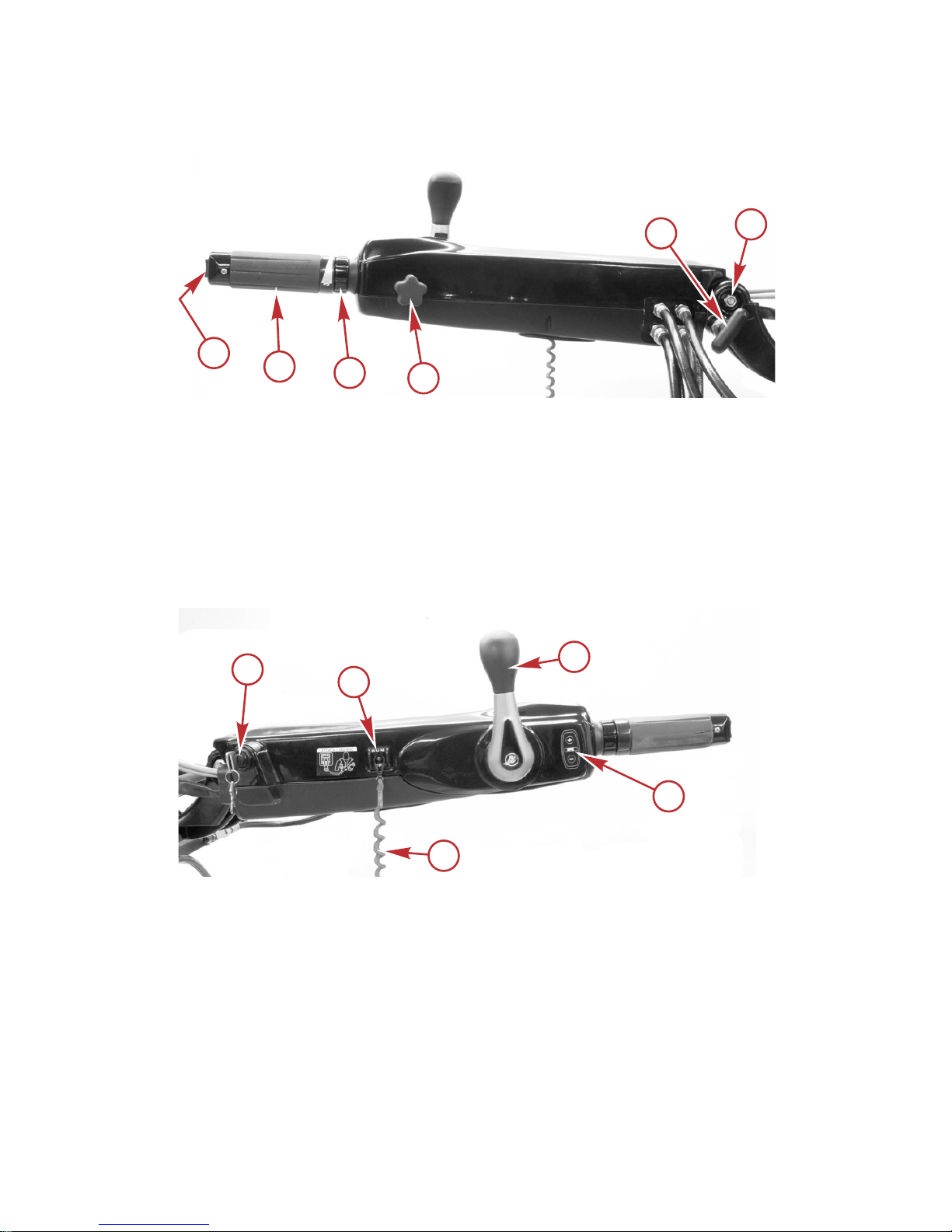
Tiller Handle Component Location
a - Power trim switch
b - Throttle grip
c - Steering actuator adjustment collar (power steering models)
d - Throttle grip friction knob
e - Tiller handle lock knob
f - Tiller handle tilt friction adjustment jam nut
a - Ignition key switch
b - Lanyard stop switch
c - Lanyard
d - Gear shift handle
e - Troll speed control switch (if equipped)
b
a
c
e
33022
d
f
a
b
c
d
e
65276
TILLER HANDLE COMPONENTS
eng 1
Page 6
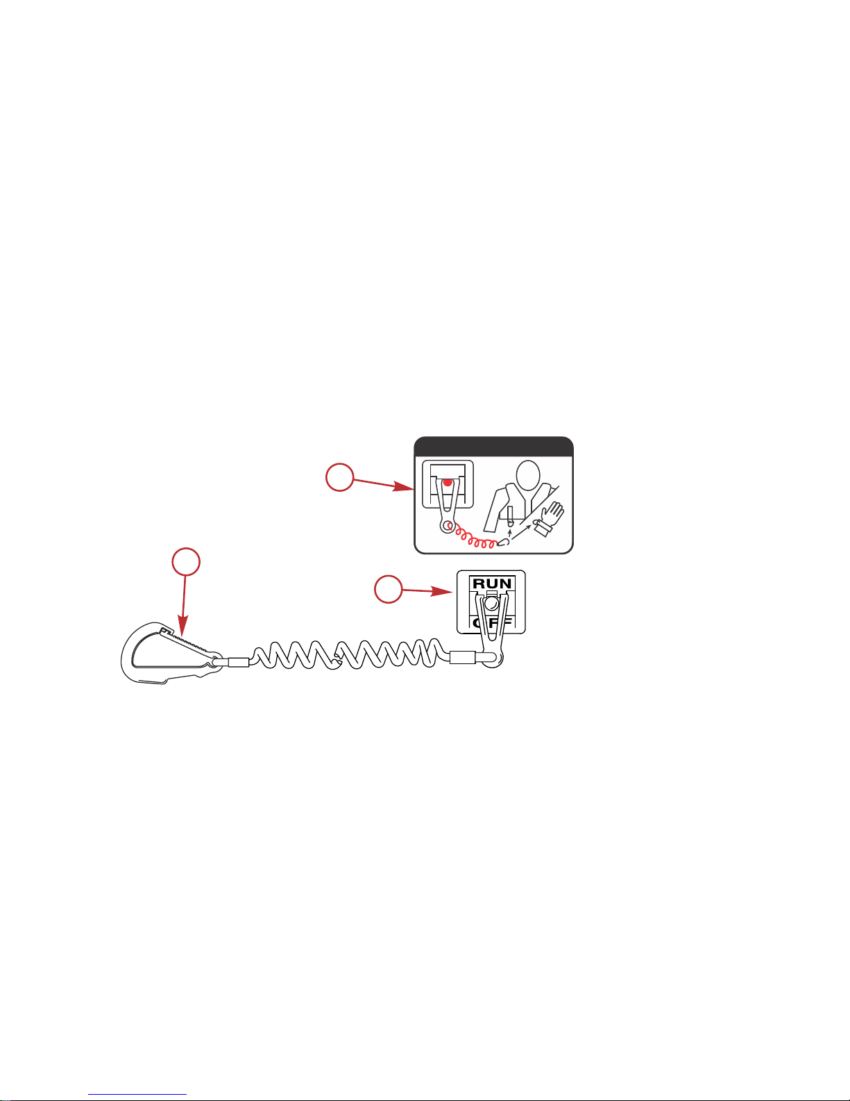
Lanyard Stop Switch
The purpose of a lanyard stop switch is to turn off the engine when the operator
moves far enough away from the operator's position (as in accidental ejection
from the operator's position) to activate the switch. Tiller handle outboards and
some remote control units are equipped with a lanyard stop switch. A lanyard
stop switch can be installed as an accessory ‑ generally on the dashboard or
side adjacent to the operator's position.
The lanyard is a cord usually 122–152 cm (4–5 feet) in length when stretched
out, with an element on one end made to be inserted into the switch and a snap
on the other end for attaching to the operator. The lanyard is coiled to make its
at‑rest condition as short as possible to minimize the likelihood of lanyard
entanglement with nearby objects. Its stretched‑out length is made to minimize
the likelihood of accidental activation should the operator choose to move
around in an area close to the normal operator's position. If it is desired to have
a shorter lanyard, wrap the lanyard around the operator's wrist or leg, or tie a
knot in the lanyard.
a - Lanyard cord clip
b - Lanyard decal
c - Lanyard stop switch
Read the following Safety Information before proceeding.
c
a
b
53910
OFF
RUN
ATTACH LANYARD
LANYARD STOP SWITCH OPERATION
2 eng
Page 7

Important Safety Information: The purpose of a lanyard stop switch is to stop
the engine when the operator moves far enough away from the operator's
position to activate the switch. This would occur if the operator accidentally falls
overboard or moves within the boat a sufficient distance from the operator's
position. Falling overboard and accidental ejections are more likely to occur in
certain types of boats such as low sided inflatables, bass boats, high
performance boats, and light, sensitive handling fishing boats operated by a
hand tiller. Falling overboard and accidental ejections are also likely to occur as
a result of poor operating practices such as sitting on the back of the seat or
gunwale at planing speeds, standing at planing speeds, sitting on elevated
fishing boat decks, operating at planing speeds in shallow or obstacle infested
waters, releasing your grip on a steering wheel or tiller handle that is pulling in
one direction, drinking alcohol or consuming drugs, or daring high speed boat
maneuvers.
While activation of the lanyard stop switch will stop the engine immediately, a
boat will continue to coast for some distance depending upon the velocity and
degree of any turn at shut down. However, the boat will not complete a full
circle. While the boat is coasting, it can cause injury to anyone in the boat's
path as seriously as the boat would when under power.
We strongly recommend that other occupants be instructed on proper starting
and operating procedures should they be required to operate the engine in an
emergency (if the operator is accidentally ejected).
!
WARNING
If the operator falls out of the boat, stop the engine immediately to reduce the
possibility of serious injury or death from being struck by the boat. Always
properly connect the operator to the stop switch using a lanyard.
!
WARNING
Avoid serious injury or death from deceleration forces resulting from
accidental or unintended stop switch activation. The boat operator should
never leave the operator's station without first disconnecting the stop switch
lanyard from the operator.
Accidental or unintended activation of the switch during normal operation is
also a possibility. This could cause any, or all, of the following potentially
hazardous situations:
• Occupants could be thrown forward due to unexpected loss of forward
motion ‑ a particular concern for passengers in the front of the boat who
could be ejected over the bow and possibly struck by the gearcase or
propeller.
• Loss of power and directional control in heavy seas, strong current, or
high winds.
• Loss of control when docking.
LANYARD STOP SWITCH OPERATION
eng 3
Page 8

KEEP THE LANYARD STOP SWITCH AND LANYARD CORD IN GOOD
OPERATING CONDITION
Before each use, check to ensure the lanyard stop switch works properly. Start
the engine and stop it by pulling the lanyard cord. If the engine does not stop,
have the switch repaired before operating the boat.
Before each use, visually inspect the lanyard cord to ensure it is in good
working condition and that there are no breaks, cuts, or wear to the cord.
Check that the clips on the ends of the cord are in good condition. Replace any
damaged or worn lanyard cords.
LANYARD STOP SWITCH OPERATION
4 eng
Page 9

Adjustments
THROTTLE GRIP FRICTION ADJUSTMENT
Turn the throttle grip friction knob to set and maintain the throttle at the desired
speed. The throttle grip friction knob can be adjusted to increase or decrease
the amount of effort needed to rotate the throttle grip. Turn the knob clockwise
to tighten friction or counterclockwise to loosen friction.
a - Throttle grip
b - Throttle grip friction knob
STEERING ACTUATOR ADJUSTMENT COLLAR (MODELS WITH
POWER STEERING)
Pivoting the throttle grip to the left or right engages the power steering. The
collar can be adjusted to increase or decrease the amount of effort needed to
pivot the throttle grip. Turn the collar counterclockwise to decrease effort or
clockwise to increase effort.
a - Steering actuator adjustment collar
33027
a
b
a
33048
TILLER HANDLE ADJUSTMENTS
eng 5
Page 10

TILLER HANDLE TILT FRICTION ADJUSTMENT
The tiller handle pivot bolt can be adjusted to increase or decrease the amount
of effort needed to move the tiller handle up and down. Loosen the jam nut on
the end of the pivot bolt and tighten or loosen the pivot bolt to obtain the
desired friction setting on the tiller handle. Hold the pivot bolt from turning and
tighten the jam nut to the specified torque.
a - Pivot bolt and jam nut
Description Nm lb‑in. lb‑ft
Tiller handle tilt friction jam nut 47 – 35
a
33353
TILLER HANDLE ADJUSTMENTS
6 eng
Page 11

TILLER HANDLE TILT LOCK—3 POSITION HANDLE
The tilt lock feature allows for the tiller handle to be tilted up and locked in
either the mid tilt angle position or full tilt angle position. When using the tilt lock
feature, move the tiller handle to the desired position and rotate the tilt lock
knob clockwise so that the cross pin will access the through slot. Push in the tilt
lock knob to engage the lock. Release the lock by pulling out the tilt lock knob
and turning it counterclockwise.
a - Mid tilt angle position
b - Full tilt angle position
c - Tilt lock knob
a
b
c
33369
TILLER HANDLE ADJUSTMENTS
eng 7
Page 12

TILLER HANDLE TILT LOCK—2 POSITION HANDLE
The tilt lock feature allows for the tiller handle to be tilted up and locked in the
full tilt angle position. When using the tilt lock feature, move the tiller handle to
the full tilt angle position and rotate the tilt lock knob clockwise so that the cross
pin will access the through slot. Push in the tilt lock knob to engage the lock.
Release the lock by pulling out the tilt lock knob and turning it
counterclockwise.
a - Full tilt angle position
b - Tilt lock knob
NOTE:
For V6 and V8 CMS applications only.
a
65288
b
TILLER HANDLE ADJUSTMENTS
8 eng
Page 13

Gear Shifting
IMPORTANT: Observe the following:
•
Never shift outboard into gear unless engine speed is at idle.
•
Do not shift outboard into reverse when the engine is not running.
• Your outboard has three gear shift positions to provide operation: forward
(F), neutral (N), and reverse (R).
• Reduce engine speed to idle before shifting.
• Always shift outboard into gear with a quick motion.
• After shifting outboard into gear, the throttle grip can be rotated to
increase speed.
F
N
33038
GEAR SHIFTING
eng 9
Page 14

Troll Control
Troll control allows the operator to maintain a set trolling speed without using
the throttle. Refer to the following table for the trolling speed range.
Trolling Speed Range
30–60 hp FourStroke 700–1000 RPM
75–150 hp FourStroke 550–1000 RPM
75–125 OptiMax 650–1000 RPM
135 hp and higher OptiMax 550–1000 RPM
135–200 Verado 4 cylinder 550–1000 RPM
V6 (175–225), V8 (200–300) CMS Mechanical 550–1000 RPM
V6 (175–225), V8 (200–300) CMS DTS 550–1000 RPM
The troll control can be shut off anytime by rotating the throttle grip out of the
idle setting, or by moving the shift handle back to neutral.
NOTE: Slight rotation of the throttle grip while steering the outboard may
disengage the troll control. Adjusting the throttle friction may prevent this.
Turn on the troll control as follows:
1. With the engine running, shift the engine into gear.
2. Set the throttle grip to the "START/SHIFT" position.
3. Press either the (+) or (–) button to turn on the troll control.
4. The RPM light will be illuminated when the troll control is turned on.
5. Press the (+) button to increase troll speed and (–) to decrease troll
speed.
Turn off the troll control as follows:
1. Rotate the throttle grip out of the "START/SHIFT" position, or move the
shift handle back to neutral.
2. The RPM light will go out when the troll control is turned off.
a - Speed control button
‑ increase speed
b - Speed control button
‑ decrease speed
c - RPM light
65117
c
a
b
TROLL CONTROL (IF EQUIPPED)
10 eng
Page 15

Power Trim
The power trim switch allows the operator to adjust the position of the outboard.
Refer to Power Trim Operation in the outboard owner's manual.
a - Power trim switch
a
33041
POWER TRIM
eng 11
Page 16

General Information
ALL MODELS
Never stand on or use the tiller handle as a step.
When the outboard is tilted up to its full range, make sure that the tiller handle
will not contact anything that can damage it.
If the tiller handle causes interference when the outboard is tilted up to the full
position, a tilt limit kit is available for models 75 hp and higher through Mercury
Marine. This kit will limit the upward tilting range of the outboard. Contact your
authorized dealer.
POWER STEERING MODELS
The power steering system has a manual steering override feature. This
feature allows the operator to steer the outboard in case the power steering
pump should ever become inoperative.
Low battery voltage may cause incorrect power steering pump operation.
Under certain operating conditions, a slight shudder may be felt in the throttle
grip. This is normal and is caused by a feedback from the power steering
pump.
Prestarting Instructions
ALL MODELS
• Before starting, read the prestarting check list, prestarting instructions,
and engine break‑in procedure in the Operation section of the outboard
owner's manual.
• Visually check the tiller handle for tightness and the steering system for
any loose components.
POWER STEERING MODELS
• Check that the manual steering override feature is functional. Before
starting the engine, manually steer the outboard through the entire range.
If the outboard cannot be steered manually, the manual steering override
feature will not function if needed. Have the outboard checked by your
authorized dealer.
• Remove the trailering clips if installed.
OPERATION
12 eng
Page 17

Starting the Engine
1. Open the fuel tank vent screw (in filler cap) on the manual venting type
fuel tanks.
19748
2. Models with primer bulb ‑ Position the fuel line primer bulb so the arrow
on the side of the bulb is pointing up. Squeeze the fuel line primer bulb
until it feels firm.
27348
3.
Set the lanyard stop switch to the "RUN" position. Refer to Lanyard Stop
Switch Operation.
19791
OPERATION
eng 13
Page 18

4. Shift outboard to neutral ("N") position.
F
N
33038
5. Rotate the throttle grip clockwise to the "START/SHIFT" position.
6. Starting a flooded engine ‑ Advance the throttle grip to half throttle
position.
a - Start/Shift
NOTE: For initial start of a new engine, or for an engine that ran out of fuel or
was drained of fuel, the fuel system should be filled by following the procedure
in the
Starting the Outboard
section of the outboard owner's manual.
7. Non‑DTS models ‑ Turn the ignition key to the "START" position. If the
engine fails to start within ten seconds, return the key to the "ON"
position, wait 30 seconds, and try again.
65328
a
OPERATION
14 eng
Page 19

8. 150 FourStroke and DTS models ‑ Turn the ignition key to the "START"
position and release the key. The electronic starting system will
automatically crank the engine for starting. If the engine fails to start, the
engine will stop cranking. Turn the key to the "START" position again until
the engine starts.
19804
9. After the engine starts, check for a steady stream of water flowing out of
the water pump indicator hole.
20766
IMPORTANT: If no water is coming out of the water pump indicator hole, stop
the engine and check the cooling water intake for obstruction. No obstruction
may indicate a water pump failure or blockage in the cooling system. These
conditions will cause the engine to overheat. Have the outboard checked by
your dealer. Operating the engine while overheated will cause engine damage.
WARMING UP ENGINE
Before beginning operation, allow the engine to warm up at idling speed for
three minutes.
Stopping the Engine
Reduce the engine speed and shift the outboard to neutral position. Turn the
ignition key to "OFF" position.
26843
OFF
ON
START
OPERATION
eng 15
Page 20

Auxiliary Light (if Equipped)
An auxiliary light is located on the bottom of the tiller handle. The light can be
turned on whenever the ignition key switch is in the "ON" or "RUN" position.
Turn the light on or off using the light switch in the light housing.
a - Auxiliary light
b - Light switch
a
b
33042
AUXILIARY LIGHT (IF EQUIPPED)
16 eng
 Loading...