

Mercury Alpha, Bravo, MerCruiser Alpha 3.0L, MerCruiser Bravo 4.3L, MerCruiser Bravo 5.0L Installation Manual
...Page 1

The following are registered trademarks of
Brunswick Corporation: Merc, MerCathode,
Mercury MerCruiser, Mercury, Mercury
Marine, Quicksilver, Ride-Guide, Thruster
and Mercury Precision Parts.
GASOLINE ENGINE STERNDRIVE MODELS
INSTALLATION MANUAL
Models Covered
Alpha
Model Serial Number or Year
3.0L
Bravo
Notice
4.3L
5.0L
5.7L
Model Serial Number or Year
4.3L
5.0L
5.7L
NOTICE
After completing installation, these instructions should be placed with the
product for the owner’s future use.
NOTICE
Predelivery preparation instructions must be performed before delivering boat
to the product owner.
0M093621 and Above
0M093633 and Above
Page 1 of 137 Printed in U.S.A. - 2001, Mercury Marine 90-860172011 NOVEMBER 2001
Page 2

GASOLINE STERNDRIVE INSTALLATION MANUAL
Table Of Contents
General Information 3. . . . . . . . . . . . . . . . .
Notice to Boat Manufacturer/Installer 3. . . . .
Torque Specifications 4. . . . . . . . . . . . . . . . . . . . .
Lubricants / Sealants / Adhesives 5. . . . . . . . . .
Special Tools 6. . . . . . . . . . . . . . . . . . . . . . . . . . . .
Alpha Notice: Increased Trim-In Range
Capability 6. . . . . . . . . . . . . . . . . . . . . . . . . . . . . .
Bravo Three Notice: Trim-In Limit Insert 7. . . . .
Quicksilver Products 7. . . . . . . . . . . . . . . . . . . . . .
Accessories 7. . . . . . . . . . . . . . . . . . . . . . . . . . .
Serial Number Decal Placement 8. . . . . . . . . . . .
Corrosion Protection 8. . . . . . . . . . . . . . . . . . . . . .
Anti-fouling Paint 9. . . . . . . . . . . . . . . . . . . . . .
Boat Construction 10. . . . . . . . . . . . . . . . . . . . . . .
Transom Thickness and Surface 10. . . . . . . .
Engine Bed 11. . . . . . . . . . . . . . . . . . . . . . . . . . .
Crankshaft Vertical Centerline 11. . . . . . . . . . .
Crankshaft Horizontal Centerline
(X-Dimension) 12. . . . . . . . . . . . . . . . . . . . . .
Transom Cutout 14. . . . . . . . . . . . . . . . . . . . . .
Seawater Connections - General
Information 16. . . . . . . . . . . . . . . . . . . . . . . . . . . .
Seawater Pickup 16. . . . . . . . . . . . . . . . . . . . .
Preliminary Connections 18. . . . . . . . . . . . . . . . .
Power Trim Pump 18. . . . . . . . . . . . . . . . . . . .
Fuel Inlet Fitting 19. . . . . . . . . . . . . . . . . . . . . .
Transom Connections 20. . . . . . . . . . . . . . . . . . .
Installing Gimbal Housing 20. . . . . . . . . . . . . .
Installing Inner Transom Plate 21. . . . . . . . . .
Connecting Speedometer Pickup 22. . . . . . .
Fluid Connections 23. . . . . . . . . . . . . . . . . . . .
Installing Steering System 25. . . . . . . . . . . . .
Transom Preparation 35. . . . . . . . . . . . . . . . . .
Driveshaft Extension Models 39. . . . . . . . . . . . . .
Engine Preparation 39. . . . . . . . . . . . . . . . . . . . . .
Engine Installation 40. . . . . . . . . . . . . . . . . . . . . . .
Exhaust System 43. . . . . . . . . . . . . . . . . . . . . .
Methods for Measuring Exhaust
Elbow Height 46. . . . . . . . . . . . . . . . . . . . . . .
Exhaust System Hose / Tube
Connections 48. . . . . . . . . . . . . . . . . . . . . . . .
Engine Alignment 49. . . . . . . . . . . . . . . . . . . . .
Hot Water Heater Installation 53. . . . . . . . . . .
Electrical Connections 55. . . . . . . . . . . . . . . . . . .
Installing Continuity Wire 55. . . . . . . . . . . . . .
Instrumentation Connections 56. . . . . . . . . . .
Trim Position Sender Connections 57. . . . . .
MerCathode Connections 57. . . . . . . . . . . . . .
Audio Warning System Connections 58. . . .
Power Trim Pump Connections 59. . . . . . . . .
Fluid Connections 61. . . . . . . . . . . . . . . . . . . . . . .
Gear Lube Monitor Hose 61. . . . . . . . . . . . . .
Power Steering Hoses 62. . . . . . . . . . . . . . . .
Bravo Models and Alpha Seawater
Cooled Models Using Sterndrive
Water Pickups 62. . . . . . . . . . . . . . . . . . . . . .
Alpha or Bravo Models Using
Alternative Water Pickups 63. . . . . . . . . . . .
Coolant Recovery System 66. . . . . . . . . . . . .
Shift Cable Installation 67. . . . . . . . . . . . . . . . . . .
Alpha Models - Drive Unit Not
Installed 67. . . . . . . . . . . . . . . . . . . . . . . . . . . .
Bravo Models 72. . . . . . . . . . . . . . . . . . . . . . . .
Throttle Cable Installation and
Adjustment 76. . . . . . . . . . . . . . . . . . . . . . . . . . . .
Sterndrive Unit Installation 77. . . . . . . . . . . . . . . .
Alpha Models 79. . . . . . . . . . . . . . . . . . . . . . . .
Bravo Models 82. . . . . . . . . . . . . . . . . . . . . . . .
All Models 86. . . . . . . . . . . . . . . . . . . . . . . . . . .
Speedometer Connection 87. . . . . . . . . . . . . . . .
Alpha Models 87. . . . . . . . . . . . . . . . . . . . . . . .
Bravo Models 88. . . . . . . . . . . . . . . . . . . . . . . .
Shift Cable Installation 89. . . . . . . . . . . . . . . . . . .
Alpha Models - Drive Unit Installed 89. . . . . .
Troubleshooting Shift Problems 95. . . . . . . . .
Predelivery Preparation 98. . . . . . . . . . . . . . . . . .
Power Steering Fluid 98. . . . . . . . . . . . . . . . . .
Filling Coolant Recovery Bottle 99. . . . . . . . .
Power Trim Pump 99. . . . . . . . . . . . . . . . . . . .
Trim Position Sender Adjustment 100. . . . . .
Propeller Selection 101. . . . . . . . . . . . . . . . . . .
Propeller Installation 102. . . . . . . . . . . . . . . . .
Battery 106. . . . . . . . . . . . . . . . . . . . . . . . . . . . .
Test Running Engine 107. . . . . . . . . . . . . . . . .
Boat In The Water Tests 111. . . . . . . . . . . . . . .
Cold Weather and Extended Storage 114. . . . .
Draining Instructions 114. . . . . . . . . . . . . . . . . . . .
3.0L Single Point Drain 115. . . . . . . . . . . . . . .
V6 And V8 Seawater (Raw-Water)
Cooled Models 119. . . . . . . . . . . . . . . . . . . . .
V6 And V8 Closed Cooled Models 122. . . . .
All Models 124. . . . . . . . . . . . . . . . . . . . . . . . . .
Wiring Diagrams 126. . . . . . . . . . . . . . . . . . . . . . .
Instrumentation 126. . . . . . . . . . . . . . . . . . . . . .
Power Trim System 128. . . . . . . . . . . . . . . . . . . . .
MerCathode System Wiring Diagram 129. . . . .
MCM Gasoline Engine Wiring Diagrams 130. . .
3.0L Engines 130. . . . . . . . . . . . . . . . . . . . . . . .
MCM 4.3L, 5.0L And 5.7L Alpha
Engines 131. . . . . . . . . . . . . . . . . . . . . . . . . . .
MCM 4.3L Bravo Engines 132. . . . . . . . . . . . .
MCM 5.0L and 5.7L Bravo Engines 133. . . .
Water Flow Diagrams 134. . . . . . . . . . . . . . . . . . .
181 cid / 3.0L Engines 134. . . . . . . . . . . . . . . .
V8 Engines - Seawater Cooled 135. . . . . . . .
V6 and V8 Engines - Closed Cooled 136. . .
Predelivery Inspection 137. . . . . . . . . . . . . . . . . .
Page 2 of 137 90-860172011
Page 3
General Information
Notice to Boat Manufacturer/Installer
Throughout this publication, Warnings and Cautions (accompanied by the International
Hazard Symbol ! ) are used to alert the manufacturer or installer to special instructions
concerning a particular service or operation that may be hazardous if performed incorrectly
or carelessly. –– Observe Them Carefully!
These Safety Alerts, alone, cannot eliminate the hazards that they signal. Strict compliance
to these special instructions when performing the service, plus common sense operation,
are major accident prevention measures.
Hazards or unsafe practices which could result in severe personal injury or death.
Hazards or unsafe practices which could result in minor personal injury or product
or property damage.
IMPORTANT: Indicates information or instructions that are necessary for proper
installation and/or operation.
GASOLINE STERNDRIVE INSTALLATION MANUAL
WARNING
CAUTION
NOTE: Refer to the Mercury MerCruiser Product Applications Manual - Gasoline Sterndrive
Models for application recommendations.
This installation manual has been written and published by Mercury Marine to aid the boat
manufacturer (OEM) in the installation of the products described herein.
It is assumed that these personnel are familiar with marine product installation.
Furthermore, it is assumed that they are familiar with, if not trained in, the recommended
installation procedures of Mercury MerCruiser product.
We could not possibly know of or advise the marine trade of all conceivable installations and
of the possible hazards and/or results of each installation. Therefore, the OEM is
responsible for any installation that does not fulfil the requirements of this manual.
It is the responsibility of the boat manufacturer to select the appropriate
engine/transom/drive package (including the correct gear ratio and propeller) for a given
boat. Mercury recommends that any new or unique hull/power package combination be
thoroughly water tested prior to sale, to verify that the boat performs as desired, and that
the engine runs in the appropriate rpm range.
It is recommended that a Mercury Marine Sales Application Engineer (SAE) be contacted
for assistance.
All information, illustrations and specifications contained in this manual are based on the
latest product information available at time of publication. As required, revisions to this
manual will be sent to all OEM boat companies.
90-860172011 Page 3 of 137
Page 4

GASOLINE STERNDRIVE INSTALLATION MANUAL
Torque Specifications
NOTE: Securely tighten all fasteners not listed below.
Description
Nm lb-in. lb-ft
Gear Lube Monitor Fitting 9 80
Speedometer Pickup Barb Fitting 1.5 13
Exhaust Pipe or Block-off Plate 31 23
Power Steering Hydraulic Hose Fittings 31 23
Power Trim Pump Hose Fittings 14 125
Propeller Nut Alpha One, Bravo One and Bravo Two
1
75 55
Front Propeller Nut Bravo Three 136 100
Rear Propeller Nut Bravo Three 81 60
Rear Engine Mounts 51 38
Steering Cable Coupler Nut 48 35
Steering System (Pivot Bolts) 34 25
Sterndrive Unit Fasteners 68 50
Transom Assembly Fasteners 31 23
Seawater Pickup Fitting 5 45
Finger tight + 1-3/4 to
Fuel Inlet Fitting
2-1/4 turns with a wrench.
DO NOT overtighten.
1
Amount specified is MINIMUM.
Page 4 of 137 90-860172011
Page 5

Lubricants / Sealants / Adhesives
Description Where Used Part Number
GASOLINE STERNDRIVE INSTALLATION MANUAL
Coupler Splines
Engine Coupler Spline Grease
2-4-C Marine Lubricant With
Teflon
Special Lubricant 101
Dexron III - Automatic
Transmission Fluid
Power Trim and Steering Fluid
Liquid Neoprene
Drive Unit Pilot
U-Joint O-rings
92-816391A4
Drive Shaft Splines
Anchor Pins
Trim Cylinder Hardware
O-ring Seals
92-825407A3
Shift Cable End
Propeller Splines
Pivot Bolts
Power Steering Bushings
Clevis Pin
92-13872A1
Steering Cable End
Propeller Splines
Power Steering Pump Obtain Locally
Power Steering Pump
Power Trim Pump
92-90100A12
Battery Terminals
MerCathode Connections
92-25711-2
Speedometer Barb Fitting
Fuel Inlet Fitting
Loctite 592 PST
Seawater Inlet Hose Fitting
Obtain Locally
Threads
Seawater Inlet Plastic Plug
Threads
Loctite 271 Seawater Inlet Nut 92-809820
Power Trim Pump
SAE 30W Engine Oil
Shift Cable Pivot Points
Obtain Locally
SAE 10W40 Engine Oil Power Trim Pump Obtain Locally
Marine Caulking
Seawater Inlet Mounting
Surfaces
Obtain Locally
Power Tune Exhaust Tubes 92-802878-57
Quicksilver High Performance
Gear Lube
Sterndrive Unit 92-802853A1
Silicone Sealant Or Equivalent Screw Shaft Obtain Locally
Equivalent products may be used.
90-860172011 Page 5 of 137
Page 6

GASOLINE STERNDRIVE INSTALLATION MANUAL
Special Tools
Description Part Number
Transom Drilling Fixture 91-43693A2
Engine Alignment Tool 91-805475A1
Shift Cable Adjustment Tool 91-12427
Engine Mount Drilling Fixture 91-806794A1
Tapered Insert Tool 91-43579
Shift Shaft Slide Stabilizer Tool 91-809815A1
Alpha Notice: Increased Trim-In Range Capability
The Alpha trim cylinders provide the capability for an increased trim-in range. A spacer can
be removed from the trim cylinders to increase the trim-in range by approximately 1-1/2
degrees. This will improve the acceleration on some boats by forcing the bow down more
quickly. If the spacers are to be removed, the boat must be water tested to ensure that the
increased trim-in range does not cause any undesired boat handling characteristics
(bow-steer, chine-walk, etc.) if the sterndrive is trimmed in while the boat is operated at
higher speeds. The boat should be tested under all conceivable load conditions and
maneuvers to ensure that the additional trim-in does not pose a problem. The final decision
and responsibility for use of the additional trim-in range is left up to the boat manufacturer.
WARNING
It is recommended that only qualified personnel adjust the Trim-In Limit Spacer.
Boat must be water tested after adjusting or removing the device to ensure that the
modified trim-in range does not cause the boat to exhibit an undesirable boat handling characteristic if the sterndrive unit is trimmed in at higher speeds. Increased
trim-in range may cause handling problems on some boats that could result in personal injury.
Page 6 of 137 90-860172011
Page 7
GASOLINE STERNDRIVE INSTALLATION MANUAL
Bravo Three Notice: Trim-In Limit Insert
NOTE: Bravo One, Two and Three Models are equipped with a Trim-In Limit Insert.
It has been brought to our attention that some boats (predominantly deep-Vee heavy boats)
will roll up on their side under certain, specific, operating conditions. The roll can be either
to port or starboard and may be experienced while moving straight ahead, or while making
a turn. The roll occurs most frequently at or near maximum speed, with the sterndrive unit
trimmed at or near full trim-in. While the boat will not roll completely over, the roll may be
sufficient to unseat the operator or passengers, and thereby create an unsafe situation.
The roll is caused by stern-lift created from excessive sterndrive unit trim-in. Under these
extreme stern-lift / bow-down conditions instability can be created which may cause the boat
to roll. Weight distribution to the stern can reduce stern-lift and, in some circumstances, help
to control the condition. Weight distribution in the bow, port or starboard, may worsen the
condition.
The T rim-In Limit Insert reduces stern-lift by preventing the sterndrive unit from reaching the
last few degrees of full trim under. While this device should reduce the rolling tendency, it
may not eliminate the tendency entirely. The need for this Trim-In Limit Insert, and its
effectiveness, can only be determined through boat testing and is ultimately the
responsibility of the boat manufacturer.
It is recommended that only qualified personnel adjust the Trim-In Limit Insert. Boat
must be water tested after adjusting the device to ensure that the modified trim-in
range does not cause the boat to exhibit an undesirable boat handling characteristic if the sterndrive unit is trimmed In at higher speeds. Increased trim-in range may
cause handling problems on some boats which could result in personal injury.
Quicksilver Products
Accessories
Quicksilver gauges, remote controls, steering systems, propellers and other accessories
are available for this product. Mercury MerCruiser recommends the use of Quicksilver parts
on all applications. Refer to Mercury Precision Parts / Quicksilver Accessories Guide for a
complete listing.
This Guide is available from:
WARNING
Mercury Marine
Attn: Parts Department
W6250 W. Pioneer Road
P.O. Box 1939
Fond du Lac, WI 54936-1939
Outside of U.S.A., order through Distribution Center or Distributor.
90-860172011 Page 7 of 137
Page 8

GASOLINE STERNDRIVE INSTALLATION MANUAL
Serial Number Decal Placement
There are three sets of engine, transom assembly and sterndrive serial number decal strips
provided with each power package. One should be used for each of the following:
• Engine Specification Decal
• Warranty Registration Card
• Operation, Maintenance and Warranty Manual identification page.
Affix serial number decals to specification / serial number decal.
Corrosion Protection
Mercury MerCruiser power packages are equipped with anodes to help protect them from
galvanic corrosion under moderate conditions. However, for severe conditions or if using
a stainless steel propeller, it is recommended that a Quicksilver Anti-Corrosion Anode Kit
and/or a MerCathode System be installed (some models have a MerCathode System as
standard equipment). A MerCathode Monitor also is available to allow the operator to check
the operation of the MerCathode System with the push of a button. (Refer to “Quicksilver
Mercury Precision Parts / Quicksilver Accessories Guide” for part numbers.)
Boats which are connected to AC shore power require additional protection to prevent
destructive low voltage galvanic currents from passing through the shore power ground
wire. A Quicksilver Galvanic Isolator can be installed to block the passage of these currents
while still providing a path to ground for dangerous fault (shock) currents. (Refer to Mercury
Precision Parts / Quicksilver Accessories Guide for part number.)
IMPORTANT: If AC shore power is not isolated from boat ground, the MerCathode
System and anodes may be unable to handle the increased galvanic corrosion
potential.
Refer to Marine Corrosion Protection Guide P/N 90-881813 01 for specific information about
marine corrosion.
Page 8 of 137 90-860172011
Page 9
Anti-fouling Paint
IMPORTANT: Corrosion damage that results from the improper application of
anti-fouling paint will not be covered by the limited warranty.
Painting Boat Hull or Boat Transom: Anti-fouling paint may be applied to boat hull and
boat transom but you must observe the following precautions:
IMPORTANT: DO NOT paint anodes or MerCathode System reference electrode and
anode, as this will render them ineffective as galvanic corrosion inhibitors.
GASOLINE STERNDRIVE INSTALLATION MANUAL
IMPORTANT: If anti-fouling protection is required for boat hull or boat transom
copper or tin base paints, if not prohibited by law, can be used. If using copper or tin
based anti-fouling paints, observe the following:
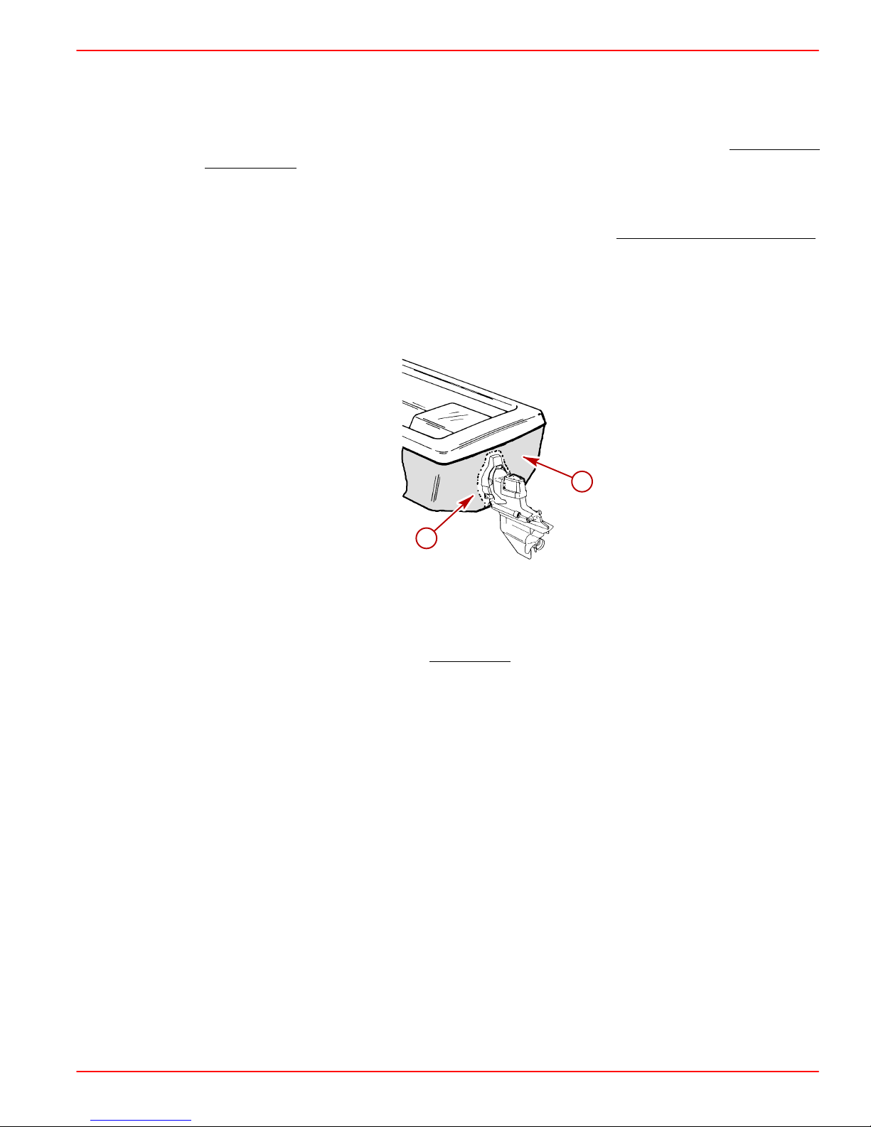
• Avoid an electrical interconnection between the Mercury MerCruiser Product,
Anodic Blocks, or MerCathode System and the paint by allowing a minimum of
1-1/2 in. (40 mm) UNPAINTED area on transom of the boat around these items.
a
b
a-Painted Boat Transom
b-Minimum 1-1/2 in. (40 mm) UNPAINTED Area Around Transom Assembly
NOTE: Sterndrive unit and transom assembly can be painted with a good quality marine
paint or an anti-fouling paint that DOES NOT
could conduct electrical current. Do not paint drain holes, anodes, MerCathode system or
items specified by boat manufacturer.
contain copper, tin, or any other material that
71176
,
90-860172011 Page 9 of 137
Page 10
GASOLINE STERNDRIVE INSTALLATION MANUAL
Boat Construction
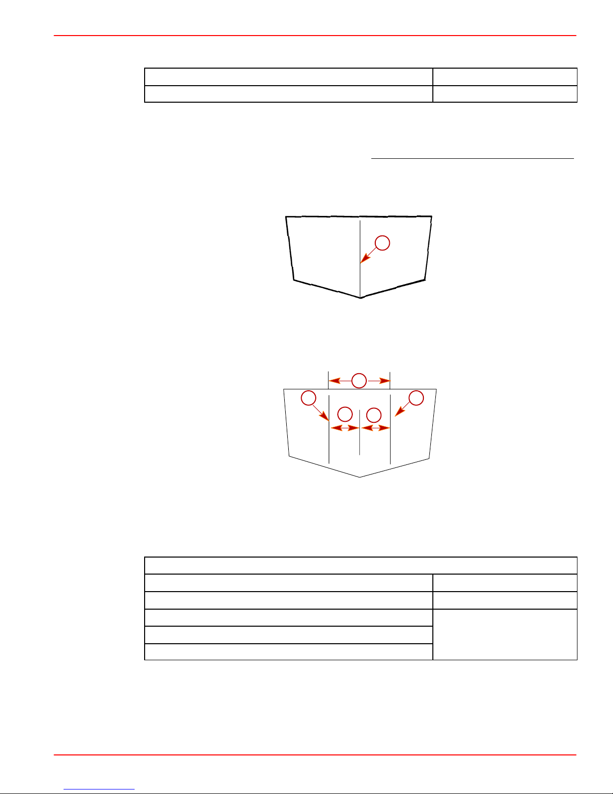
Transom Thickness and Surface
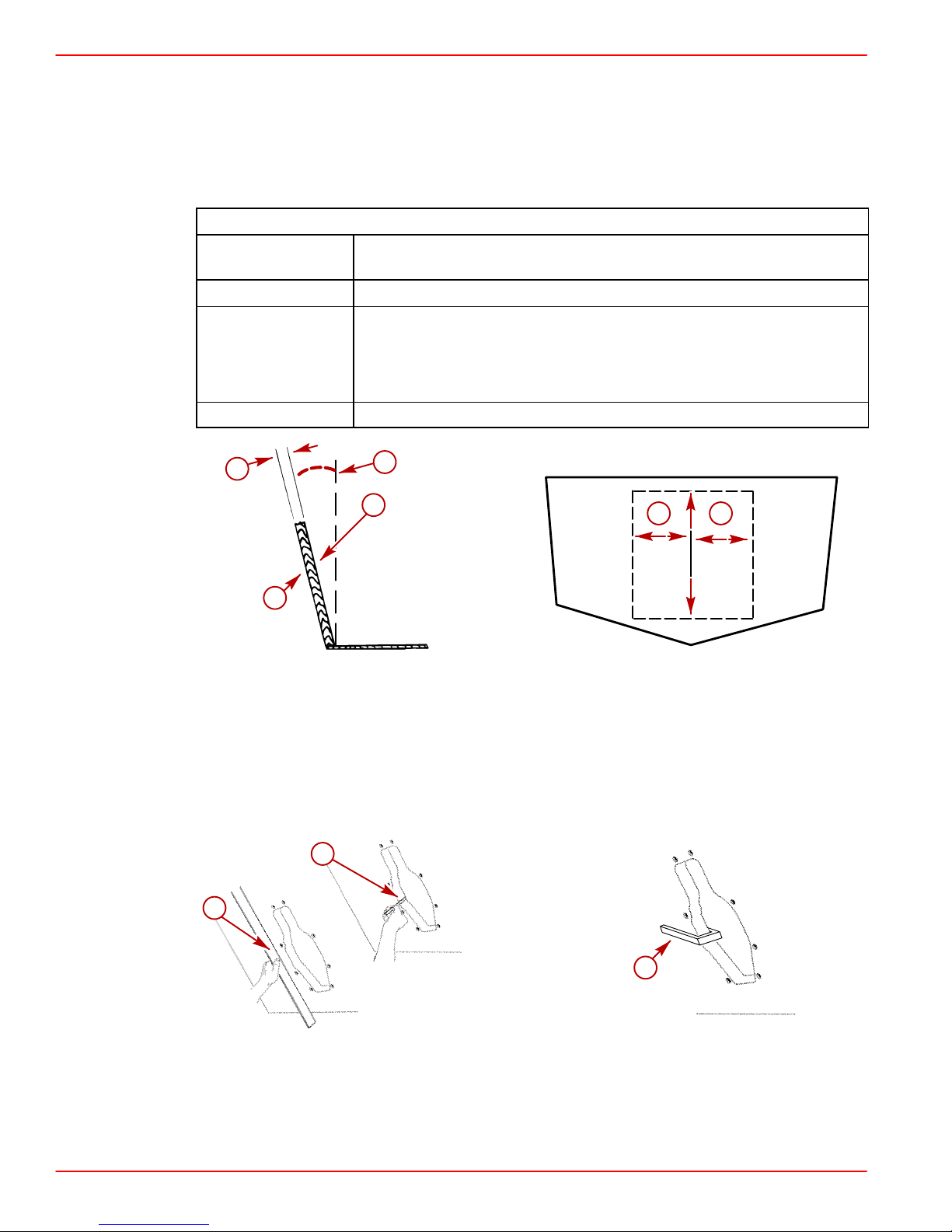
IMPORTANT: Transom thickness and surface plane (flatness) must be controlled
where the sterndrive unit mounts.
Thickness Between 2 - 2-1/4 in. (51 - 57 mm) for 8 in. (203 mm) to either
side of the vertical centerline
Parallelism Inner and outer surfaces must be parallel within 1/8 in. (3 mm)
Flatness Transom surfaces in area where transom assembly will be
mounted (includes vertical as well as horizontal dimensions):
Inner Surface – Flat within1/8 in. (3 mm)
Outer Surface – Flat within1/16 in. (2 mm)
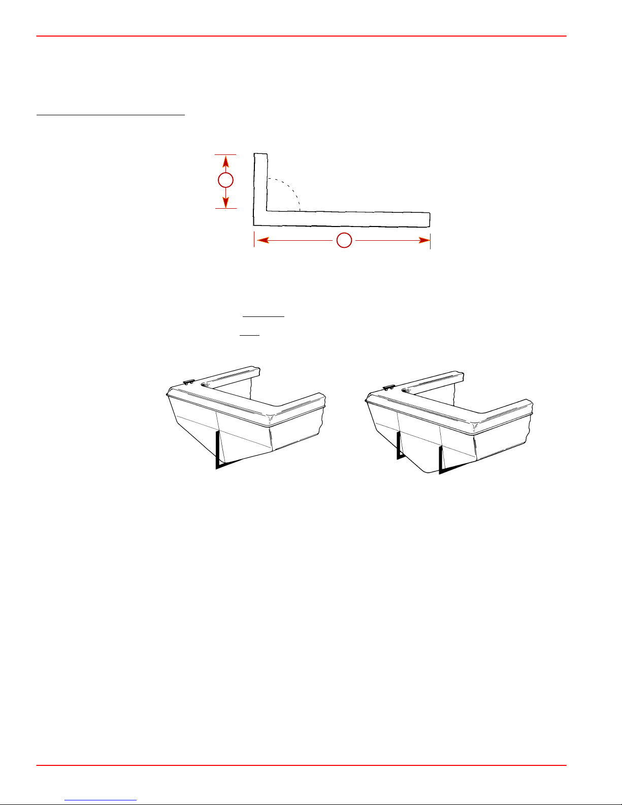
Angle 10 -16 Degrees
Transom Specifications
a
e
b
c
a-Transom Thickness
b-Inner Surface
c-Outer Surface
d-Transom Plate Coverage
e-Transom Angle
a
b
22170
d d
72700
a-Measuring Thickness
b-Measuring Flatness
c-Suitable Mandrel To Check For Uniform Transom Thickness
Page 10 of 137 90-860172011
70004
c
75479
Page 11
Engine Bed
Difference Between Starboard and Port Engine Mount 22-1/2 in. (572 mm)
Mount Adjustment Up and Down (minimum) 1/4 in. (6 mm)
NOTE: Although the engine mounts allow some adjustment, it is a good practice to ensure
that the front and rear mount locations in the vessel are parallel and in the same plane. This
may be checked by tying a string from the left front mount location to the right rear mount
location and another from right front to left rear. The strings should touch where they cross
Crankshaft Vertical Centerline
1. Locate and mark boat vertical centerline on transom.
GASOLINE STERNDRIVE INSTALLATION MANUAL
.
a
71620
a-Vertical Centerline
2. For Dual Engines: Locate and mark crankshaft vertical centerlines “a” on transom.
b
a a
c
c
22033
a-Crankshaft Vertical Centerline
b-Minimum Distance Between Crankshaft Vertical Centerlines
c-Crankshaft Vertical Centerlines Must Be An Equal Distance From Boat Vertical
Centerline
Minimum Distance Between Crankshaft Vertical Centerlines (Dual Side-By-Side)
Model in. (mm)
181 cid / 3.0L 28 (710)
262 cid / 4.3L
305 cid / 5.0L
350 cid / 5.7L
90-860172011 Page 11 of 137
33 (838)
Page 12
GASOLINE STERNDRIVE INSTALLATION MANUAL
Crankshaft Horizontal Centerline (X-Dimension)
X-Dimension can be measured by the 90 degree Tool Method or by the Tape Measure
Method.
90 DEGREE TOOL METHOD
1. Construct 90 degree tool.
a
90°
b
71621
a-13-9/16 in. (345 mm)
b-Measurement: 4 ft. (1.2 m)
To Lower Drive Unit - Subtract
To Raise Drive Unit - Add
from dimension “a.”
to dimension “a.”
IMPORTANT: This dimension should only be raised or lowered after proper testing.
71622
71623
Single Engine Dual Engine
2. Place 90 degree tool along boat bottom at vertical centerline.
3. Locate the point at which top of tool contacts transom on vertical centerline. This is the
crankshaft horizontal centerline or X-Dimension.
4. Draw a line perpendicular to vertical centerline at crankshaft horizontal centerline.
Page 12 of 137 90-860172011
Page 13

TAPE MEASURE METHOD
1. Determine X-Dimension from the following chart.
GASOLINE STERNDRIVE INSTALLATION MANUAL
Transom Angle
(degrees)
This dimension should only be raised or lowered after proper
testing.
16 14-5/16 in. (364 mm)
15 14-1/4 in. (362 mm)
14 14-3/16 in. (360 mm)
13 14-1/8 in. (359 mm)
12 14-1/16 in. (357 mm)
11 14 in. (356 mm)
10 13-15/16 in. (354 mm)
2. Measure up from the boat bottom the amount shown on the chart for the appropriate
transom angle.
71622
71623
Single Engine Dual Engine
3. Draw a line perpendicular to vertical centerline at crankshaft horizontal centerline.
90-860172011 Page 13 of 137
Page 14

GASOLINE STERNDRIVE INSTALLATION MANUAL
Transom Cutout
IMPORTANT: The following instructions will provide a sterndrive unit mounting
location that is suitable for most boats. Best mounting location for a particular boat,
however, can be determined only by testing.
1. Below 25 mph (40 km/h):
2. Heavy Duty Applications:
3. Above 25 mph (40 km/h):
4. Above 50 mph (80 km/h):
Subtract 1/2 in. (13 mm) from X-Dimension.
Subtract 1 in. (25 mm) from X-Dimension.
Use X-Dimension shown.
The X-Dimension can be increased to improve performance
in some applications. However, pulling power for skiing will decrease. During testing,
X-Dimension should be increased 1/2 in. (13 mm) at a time until desired performance
is achieved but in no case should it ever be increased by more than:
Maximum Increase In X-Dimension
Alpha 2-1/2 in. (64 mm)
Bravo One and Two 3 in. (76 mm)
Bravo Three 1 in. (25 mm)
Extreme care should be taken when raising drive unit to ensure that water supply does not
become aerated. Use clear water inlet hose to monitor incoming water and monitor engine
temperature gauge to ensure engine does not overheat.
In applications where cooling water to the engine is supplied by a through the hull
or through the transom fitting, the sterndrive height will not cause cooling water aeration.
IMPORTANT: Damage to Mercury MerCruiser products caused by too high of an
installed height will not be covered by Mercury MerCruiser warranty.
Page 14 of 137 90-860172011
Page 15
GASOLINE STERNDRIVE INSTALLATION MANUAL
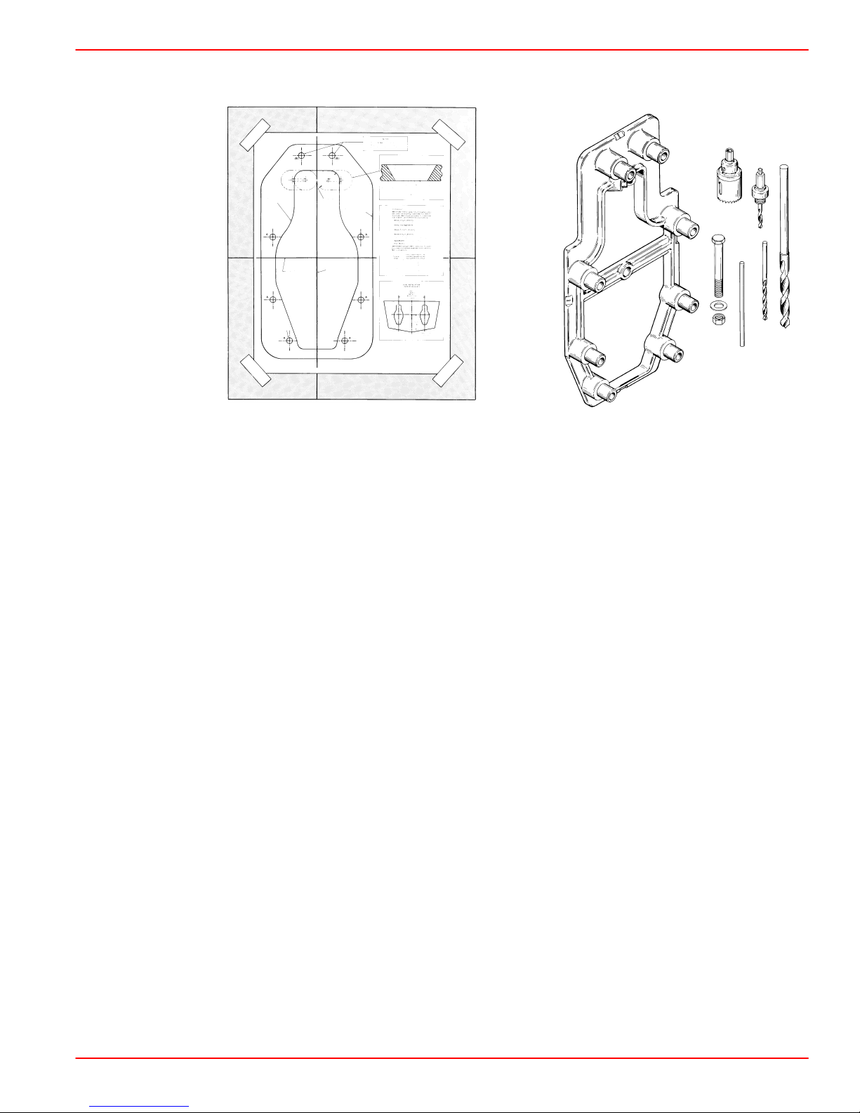
5. Cut out transom using the Template or the Transom Drilling Fixture Kit (purchased
separately).
90-79135--3
50017
22056
Transom Cutout Template Transom Drilling Fixture Kit
6. Follow instructions indicated on template or provided with drilling fixture.
7. Ensure that centerlines on either the template or transom drilling fixture align with lines
previously marked on transom.
8. Drill 1/4 in. (6 mm) pilot holes for hole saw guide at a 60 degree angle and cut on the
line when making transom cutout. If cutout is made incorrectly, drive unit steering lever
may contact transom, thus limiting steering travel.
9. Seal inside edge of transom cutout opening with a suitable sealant to prevent water
absorption and deterioration of transom.
10. Cut drain hole and install drain plug flange with appropriate fasteners.
90-860172011 Page 15 of 137
Page 16
GASOLINE STERNDRIVE INSTALLATION MANUAL
Seawater Connections - General Information
This section covers through the hull and through the transom water inlets only. For information on sterndrive water inlet connections, refer to the appropriate section after engine installation.
IMPORT ANT: Seal the inside edges of any hole made through the hull with a suitable
sealant to prevent water absorption and deterioration.
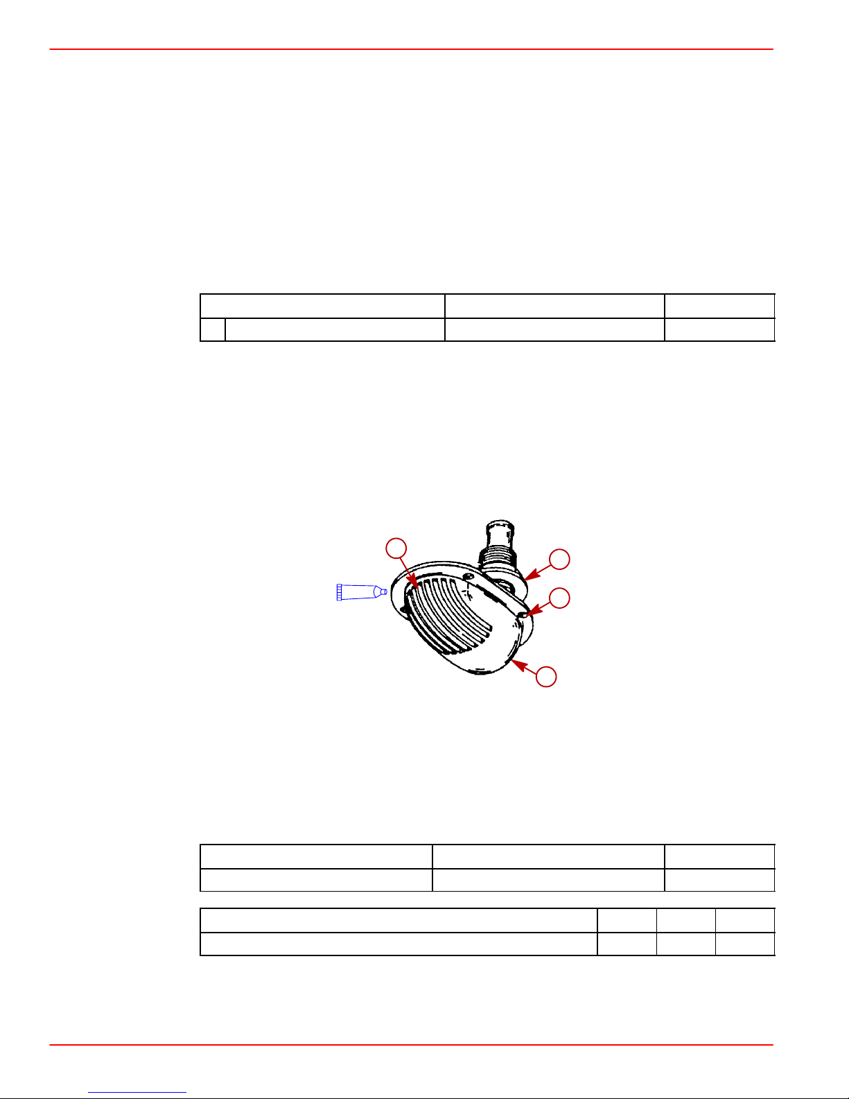
Seawater Pickup
THROUGH THE HULL MOUNTED
Description
A Marine Caulking Mounting Surfaces Obtain Locally
1. Seal inside edges of 1-3/4 in. (44 mm) hole in hull using a suitable sealer.
2. Apply marine caulking (sealer) to mounting surface on seawater pickup where hull
contact will occur when installed.
IMPORT ANT: Seawater inlet slots must face forward - parallel with the flow of water.
3. Ensure slots in seawater pickup are facing forward (toward bow of boat) and install
seawater pickup through hull.
4. Fasten pickup with four appropriate mounting screws (if so designed).
b
A
Where Used Part Number
d
c
a
72639
a-Seawater Pickup
b-Seawater Inlet Slots
c-Mounting Screw Holes (If Equipped)
d-Nut
5. Apply marine caulking as needed inside boat. Apply sealant to threads of nut and install
on pickup on inside of boat and torque nut.
Description
Loctite 271 Seawater Inlet Nut 92-809820
Description Nm lb-in. lb-ft
Nut 42 35
NOTE: If pickup being installed does not have mounting screws on underside where
mounted to hull, be certain, after nut is torqued, that slots are still facing forward.
Page 16 of 137 90-860172011
Where Used Part Number
Page 17
TRANSOM MOUNTED
1. Seal the inside edges of the 1-1/2 in. (38 mm) hole hose fitting.
2. Ensure that the hose fitting and plastic plug are in place and threads have been sealed
GASOLINE STERNDRIVE INSTALLATION MANUAL
prior to tightening each securely.
Description
Where Used Part Number
Hose Fitting Threads
A Loctite 592 PST
Plastic Plug Threads
Obtain Locally
B Silicone Sealant Or Equivalent Screw Shaft
NOTE: Use a sharp knife or wood chisel to remove excess plastic plug material so that plug
is flush with pickup casting.
3. Position one flat washer and one rubber O-ring on each 5/16 in. x 4 in. (102 mm) long,
round head screw. Coat each screw shaft with sealant.
4. Place new gasket on pickup housing and hold pickup in place on transom. Install four
round head screws (with washers and O-rings in place) into pickup mounting holes and
through drilled 21/64 in. (8 mm) holes in transom.
b
d
A
a
e
B
f
c
g
A
h
i
j
72640
a-Hose Fitting
b-Nut (4)
c-Gasket
d-O-ring (4)
e-Washer (4)
f-Screw (4)
g-Plastic Pug
h-Pickup
i-Screen
j-Screw (2)
90-860172011 Page 17 of 137
Page 18
GASOLINE STERNDRIVE INSTALLATION MANUAL
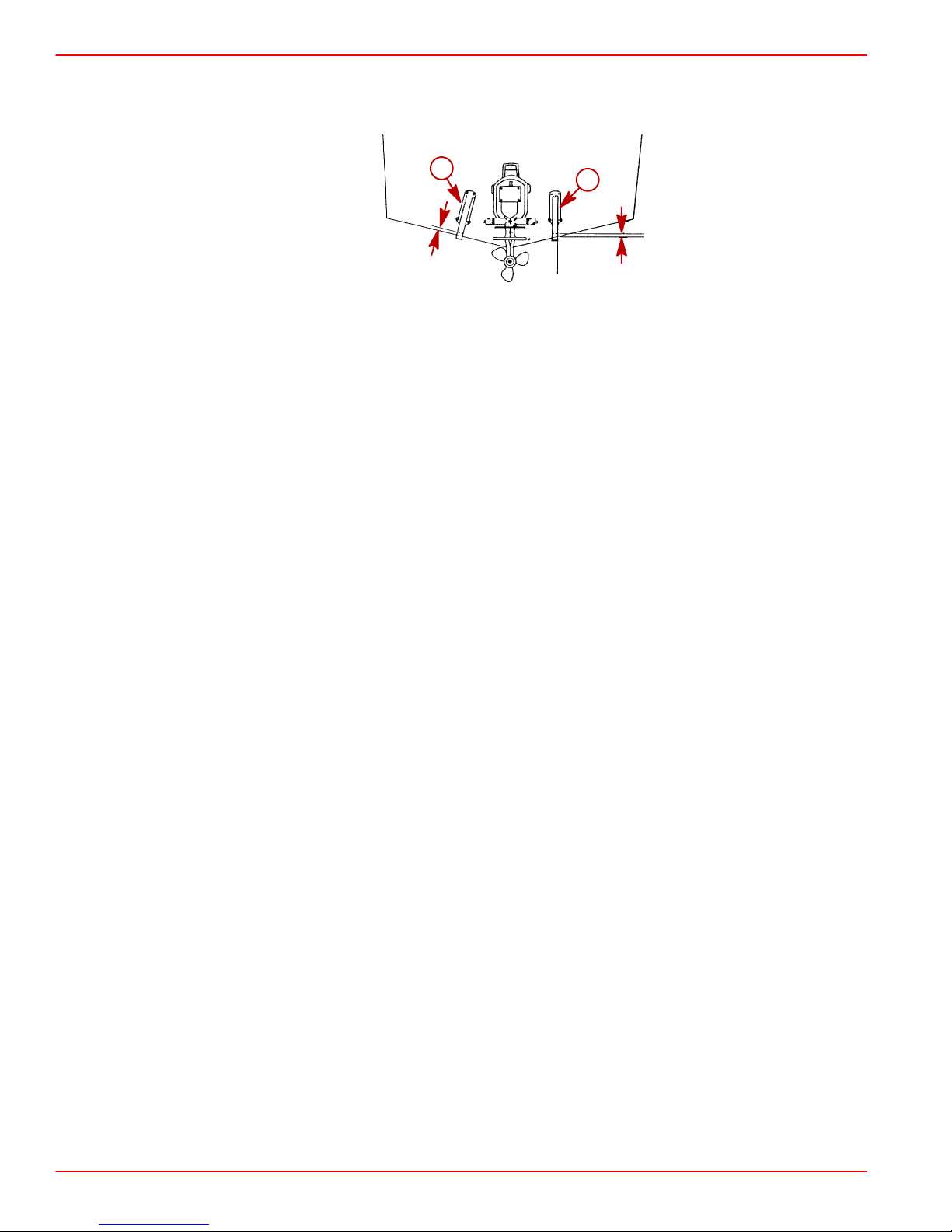
NOTE: Some installations may have 7/32 in. (5 mm) holes drilled in transom using four 5/16
in. diameter stainless steel lag bolts in place of round head screws. In any case, flat washers
and O-rings are required as outlined.
Water Pickup Installed on Transom
a-Diagonal Mount - Leading Edge Of Pickup 1/8 in. (3.2 mm) From Boat Bottom.
b-Vertical Mount - Corner Of Leading Edge Of Pickup 1/8 in. (3.2 mm) From Boat
Bottom
5. Secure water pickup from inside with locknuts and washers (unless using lag bolts).
6. Tighten fasteners securely.
Preliminary Connections
Power Trim Pump
1. Select an appropriate mounting location for the trim pump that:
• Is within length limits of black and gray hydraulic hoses coming from gimbal housing
assembly.
a
b
72641
• Is close to the battery so that trim pump battery leads can be connected.
• Allows easy access to trim pump oil fill and vent locations.
• Is in an area where pump will not be exposed to water.
• Prevents the power steering booster cylinder from coming in contact with the trim pump
when the steering wheel is turned in either direction (right or left).
NOTE: Template 90-863152 provides mounting hole location for floor or transom mounting.
2. Remove the cap plug.
3. Mount the pump in the desired location.
Page 18 of 137 90-860172011
Page 19
Fuel Inlet Fitting
IMPORTANT: The following information is provided to ensure proper installation of
brass fittings or plugs installed into fuel pump or fuel filter base:
• Use #592 Loctite Pipe Sealant with Teflon on threads of fuel inlet fittings or plugs.
• Fuel inlet fittings or plugs should first be threaded into fuel pump or fuel filter
• Fuel inlet fittings or plugs should then be tightened an additional 1-3/4 to 2-1/4
• To prevent over-tightening when installing a fuel line, the brass fittings should be
Boating standards (NMMA, ABYC and others) and Coast Guard regulations must
be adhered to when installing fuel delivery system.
Avoid gasoline fire or explosion. Improper installation of brass fittings or plugs into
fuel pump or fuel filter base can crack casting and/or cause a fuel leak.
GASOLINE STERNDRIVE INSTALLATION MANUAL
DO NOT USE TEFLON TAPE.
base until finger tight.
turns using a wrench. DO NOT OVERTIGHTEN.
held with a suitable wrench as fuel inlet fittings are tightened securely.
WARNING
WARNING
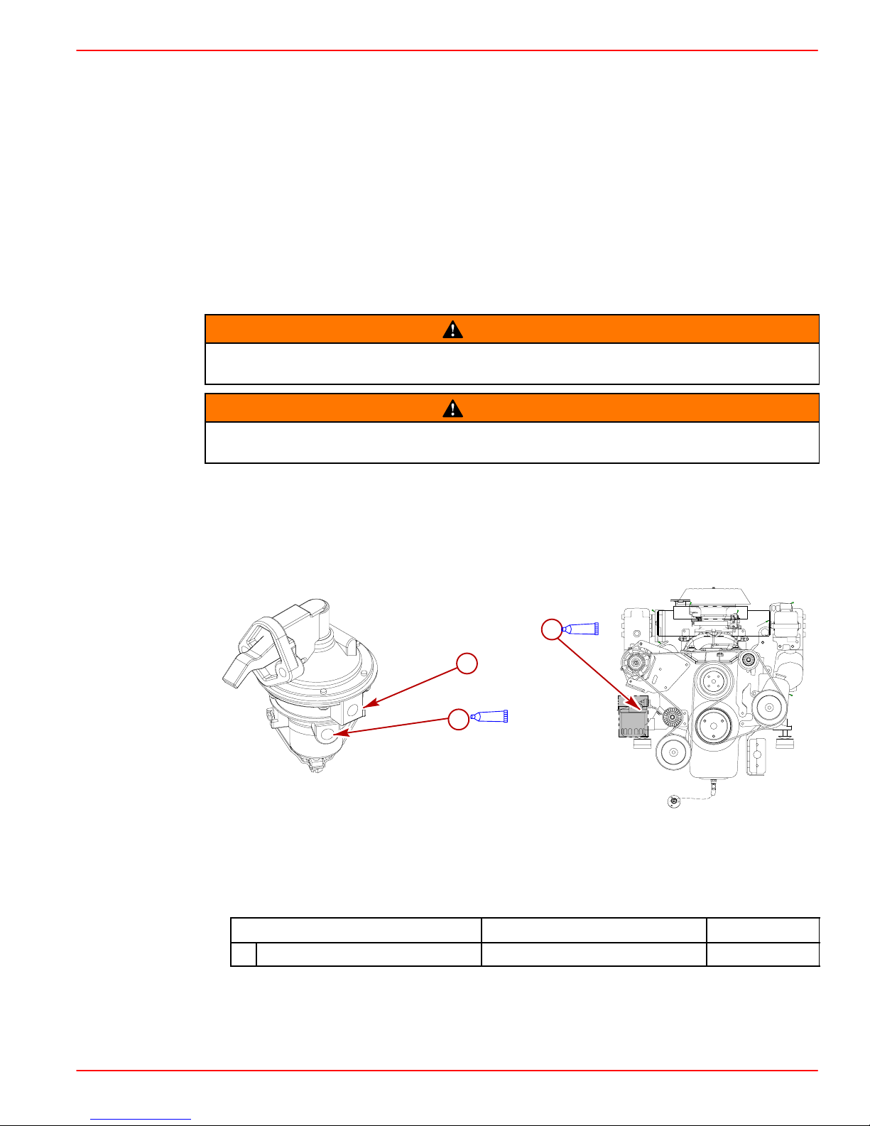
1. Remove plastic plug from fuel inlet hole.
2. Apply sealant to threads of fuel inlet fitting. DO NOT USE TEFLON TAPE.
3. Install fuel inlet fitting. To prevent cracking the casting or causing fuel leaks, turn fuel inlet
fitting in by hand until finger tight, then tighten connector to 1-3/4 to 2-1/4 turns with
wrench. DO NOT overtighten.
a
A
b
A
a
78165
3.0L Model Typical V6 And V8 Models
a-Fuel Inlet Hose Connects Here
b-Fuel Outlet
77108
Description
A Loctite 592 Fuel Inlet Fitting Obtain Locally
90-860172011 Page 19 of 137
Where Used Part Number
Page 20
GASOLINE STERNDRIVE INSTALLATION MANUAL
SPECIAL INFORMATION ABOUT ELECTRIC FUEL PUMPS
CAUTION
The electric fuel pump and factory installed water separating fuel filter have been
carefully designed to function properly together . Do not install additional fuel filters
and/or water separating fuel filters between fuel tank and engine.
The installation of additional filters may cause:
• Fuel Vapor Locking
• Difficult Warm-Starting
• Piston Detonation Due to Lean Fuel Mixture
• Poor Driveability
Transom Connections
Installing Gimbal Housing
1. Carefully remove transom assembly from shipping carton.
2. Remove and read all tags attached to transom assembly.
a
b
a-Dust Cover
b-Shipping Hardware
3. Remove the shipping hardware.
4. Remove the dust cover if boat will be shipped with drive installed.
5. Retain the serial number envelope.
22027
Page 20 of 137 90-860172011
Page 21
Installing Inner Transom Plate
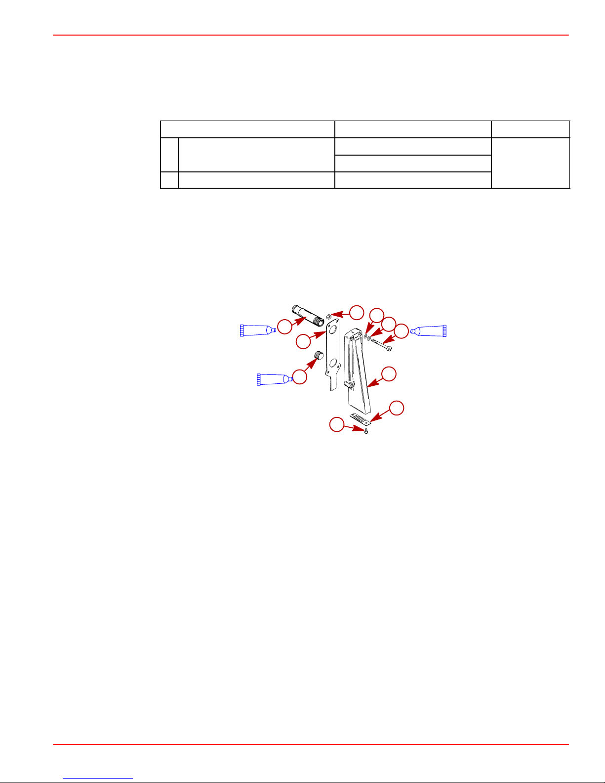
1. Insert wires, hoses and shift cable through appropriate openings in inner transom plate.
2. Position gimbal housing on transom and hold in place.
IMPORTANT: Tighten the transom assembly fasteners using an X-pattern torque
sequence, starting from the middle fasteners. Tighten in small increments and go
around the pattern several times until the proper torque is achieved.
3. Secure transom assembly with hardware as shown. Torque the hardware.
GASOLINE STERNDRIVE INSTALLATION MANUAL
Description
Nm lb-in. lb-ft
Transom Assembly Hardware 31 23
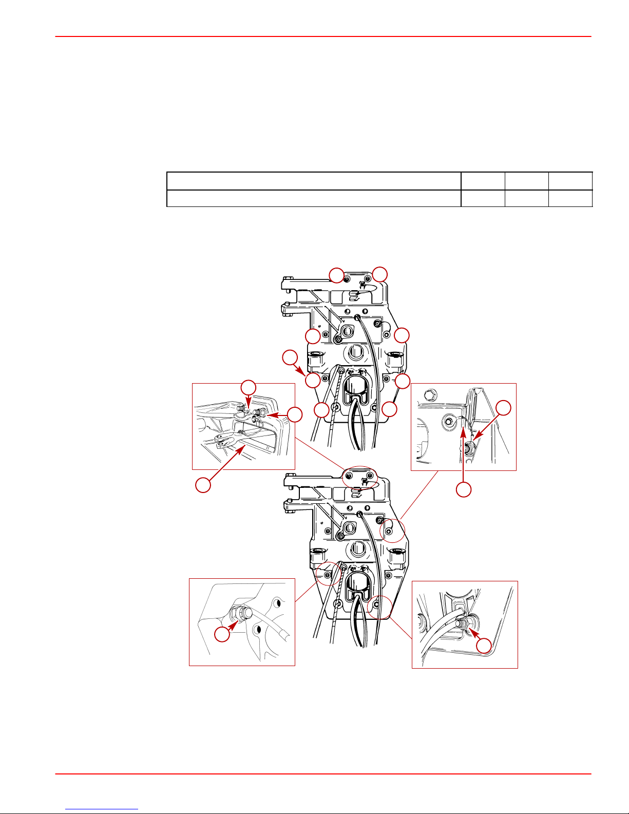
4. Attach continuity wires.
IMPORTANT: Steering lever continuity circuit wire must be positioned as shown to
avoid stressing wire when steering lever moves.
5
3
7
2
b
a
71626
1
8
a
4
6
a
71628
c
a
70005
a-Locknuts And Flat Washers (8)
b-Torque Sequence
c-Continuity Wire
71627
c
a
71629
90-860172011 Page 21 of 137
Page 22
GASOLINE STERNDRIVE INSTALLATION MANUAL
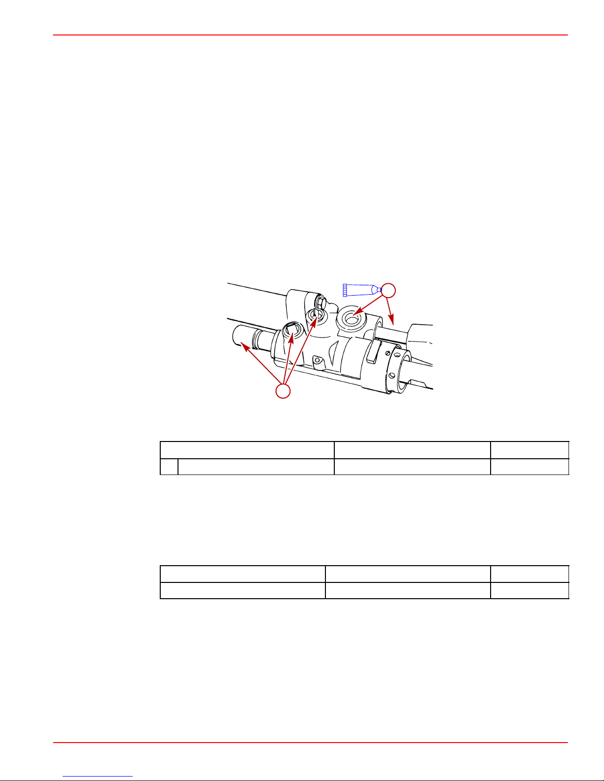
5. Install the water inlet fitting and j-clip for the gear lube and the speedometer hose.
a
a-Water Inlet Fitting
b-J-clip
6. Torque J-clip fasteners.
Description
J-Clip Fasteners 5 45
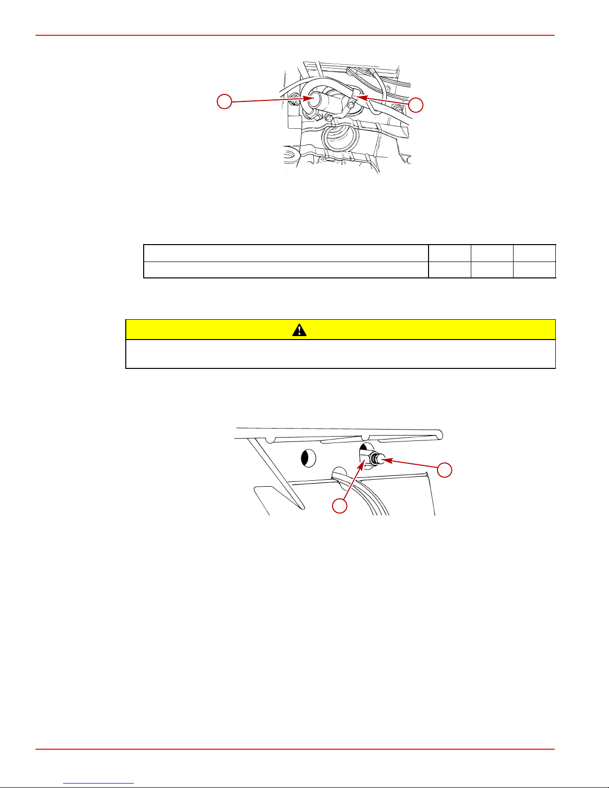
Connecting Speedometer Pickup
Excess water in bilge can damage engine or cause boat to sink. Do not remove plug
from speedometer pickup tube fitting unless connection is to be utilized.
The connection for the speedometer pickup can be accessed through a hole and fitting in
the inner transom plate.
b
77916
Nm lb-in. lb-ft
CAUTION
1. Remove plug from speedometer pickup tube fitting.
b
a-Plug
b-Inner Transom Plate Fitting
a
70037
Page 22 of 137 90-860172011
Page 23
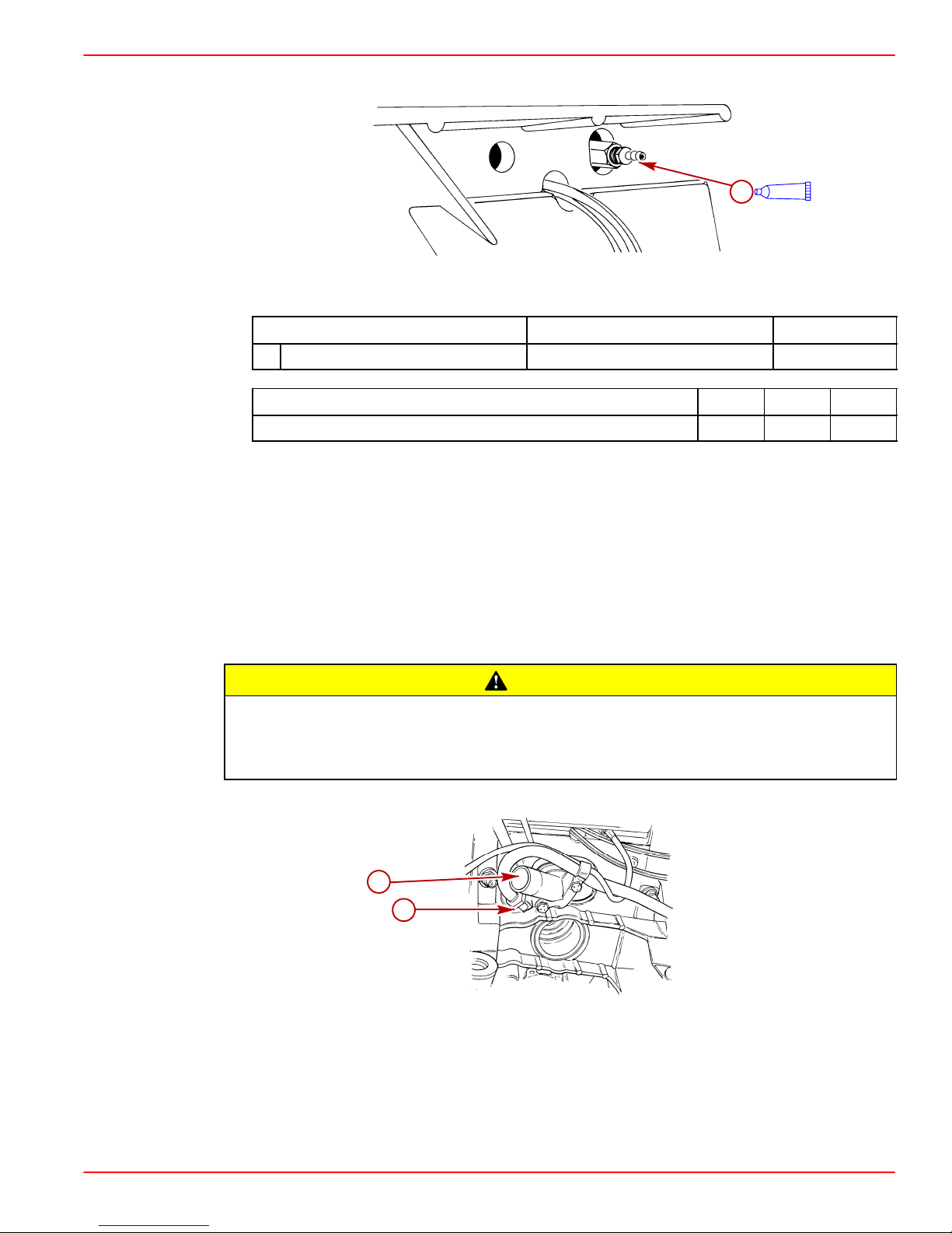
GASOLINE STERNDRIVE INSTALLATION MANUAL
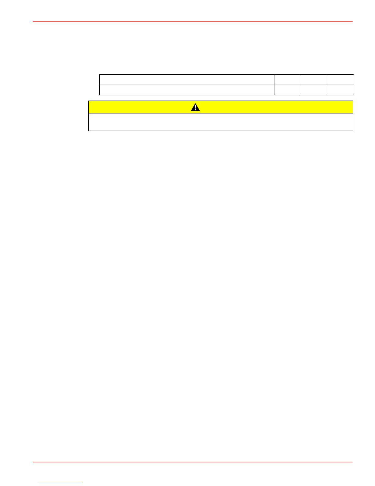
2. Apply sealant to threads of barb fitting. Install and torque the barb fitting.
Description
A Loctite 592 Speedometer Barb Fitting Obtain Locally
Description Nm lb-in. lb-ft
Barb Fitting 1.5 13
3. Connect a 5/32 in. (4 mm) speedometer hose (not provided) hose from speedometer
to barb fitting. Secure hose with cable tie.
4. Secure the hose to the transom with the hose clip and screw that are provided in the
parts bag.
NOTE: The hose must not come into contact with the steering system components or the
engine coupler and drive shaft.
Fluid Connections
1. Connect the gear lube monitor hose to the quick release 90 degree fitting.
a-Barb Fitting
a
A
70015
Where Used Part Number
CAUTION
Avoid sterndrive unit damage. Quick release button on gear lube monitor 90 degree
hose fitting may not lock on gimbal housing if touching or depressed by water inlet
fitting or block-off plate, if equipped. Failure to do so could result in a loose 90
degree fitting causing a loss of gear lube and damage to drive unit.
2. Connect 90 degree fitting to the gimbal housing.
a
b
77916
a-Water Inlet Fitting
b-90 Degree Fitting
90-860172011 Page 23 of 137
Page 24
GASOLINE STERNDRIVE INSTALLATION MANUAL
NOTE: The quick release button on hose fitting must be positioned away from water inlet
fitting, or block-off plate if equipped. Release button must not contact water fitting or
block-off plate, if equipped.
NOTE: The hose must not come into contact with the steering system components or the
engine coupler and drive shaft.
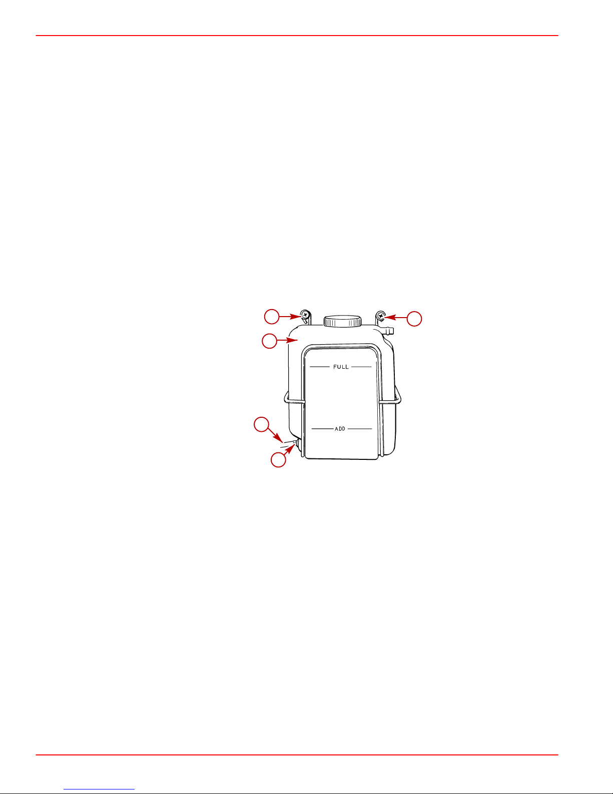
3. Select a mounting location for coolant recovery bottle and mounting bracket that meets
all of the following:
• Within limits of clear plastic tubing.
• Level with or above the heat exchanger fill neck.
• Accessible for observing coolant level and filling.
4. Mount coolant recovery bottle and mounting bracket in desired location using two
3/4 in. (19 mm) long screws and flat washers.
5. Route plastic tubing to recovery bottle. Ensure that tubing is positioned away from any
moving parts. Cut plastic tubing as required and connect to bottom connection on
recovery bottle and secure with tubing clamp provided.
6. Fasten plastic tubing to boat, as necessary , with 2 hose clips and 1/2 in. (13 mm) long
screws (provided).
b
a
c
d
a-Recovery Bottle And Mounting Bracket
b-Screws And Flat Washers
c-Plastic Tubing
d-Tubing Clamp
b
71712
Page 24 of 137 90-860172011
Page 25
Installing Steering System
HYDRAULIC (HELM) STEERING
If your power package is equipped with Compact Hydraulic Steering, refer to the Compact
Hydraulic Steering Installation Instructions in the box with the compact hydraulic steering
components. Complete the installation of the hydraulic steering system before proceeding
to Transom Preparation.
POWER STEERING
NOTE: For dual installations, power steering unit can be mounted on port or starboard
transom assembly . Measure exact distance between power package centerlines. Select a
tie bar from Mercury Precision Parts / Quicksilver Accessory Guide. Refer to tie bar
installation instructions before proceeding.
1. Inspect the bushings for debris. Lubricate the bushings.
GASOLINE STERNDRIVE INSTALLATION MANUAL
a
A
b
73898
a-Bushings
b-Shipping Hardware
Description
Where Used Part Number
A Special Lubricant 101 Bushings 92-13872A1
2. Remove shipping hardware.
3. Remove the cotter pins.
4. Loosen the upper and lower pivot bolts and ensure that the threads are well lubricated..
Add lubricant as necessary.
Description Where Used Part Number
Special Lubricant 101 Pivot Bolts 92-13872A1
90-860172011 Page 25 of 137
Page 26
GASOLINE STERNDRIVE INSTALLATION MANUAL
5. Install steering assembly as follows:
a. Position steering assembly so that pivot bolts will enter bushings in pivot block or
power steering control valve.
b. Install upper and lower pivot bolts along with tab washers. Ensure that tab washer
tangs straddle the ridge on inner transom plate.
c. Turn pivot bolts all the way in by hand to ensure proper alignment.
d. Ensure steering assembly pivots freely.
6. Torque pivot bolts. Bend tab washer tangs against corresponding flats on bolt heads.
c
a
b
a
c
73900
a-Tab Washers
b-Ridge
c-Pivot Bolts
Description
Pivot Bolts 34 25
NOTE: It may be necessary to tighten further to align flats on pivot bolt with tangs on tab
washer.
Nm lb-in. lb-ft
73899
Page 26 of 137 90-860172011
Page 27
GASOLINE STERNDRIVE INSTALLATION MANUAL
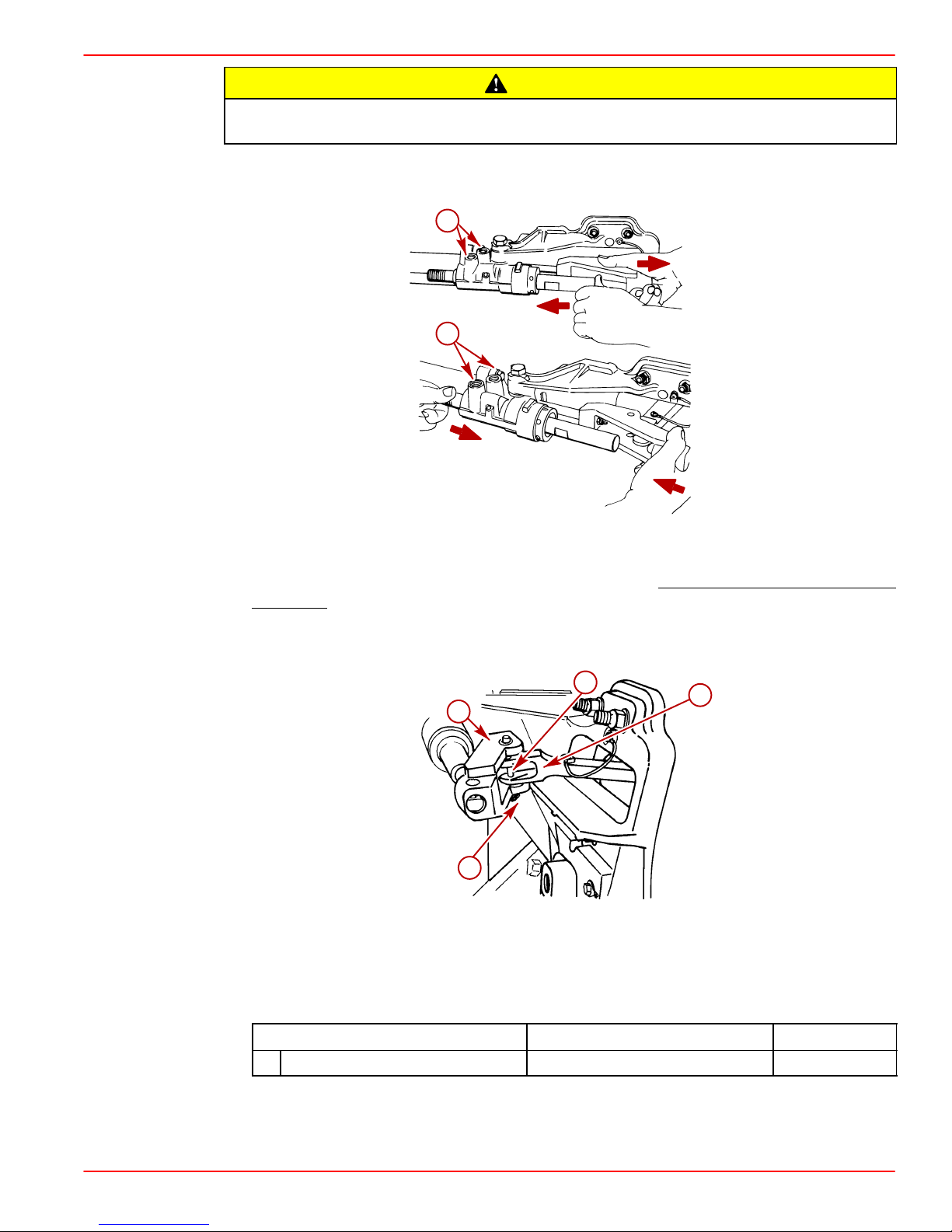
CAUTION
MOVING THE CONTROL VALVE RAM with the hoses disconnected will expel fluid
from the control valve ports. Wear eye protection.
7. The control valve ram may be stiff and difficult to move when you attempt to pull it out
or push it in for installation. Move the assembly in the directions shown below.
a
a
74145
74144
a-Control Valve Ports
8. Connect clevis to steering lever. Lubricate clevis pin. Be sure to spread both ends of
cotter pin.
NOTE: Make sure to insert clevis pin from the top to ensure that cotter pin hole is as shown
in the diagram.
c
b
a
a-Clevis
b-Steering Lever
c-Clevis Pin
d-Cotter Pin
Description
A Special Lubricant 101 Clevis Pin 92-13872A1
90-860172011 Page 27 of 137
d
71904
Where Used Part Number
Page 28
GASOLINE STERNDRIVE INSTALLATION MANUAL
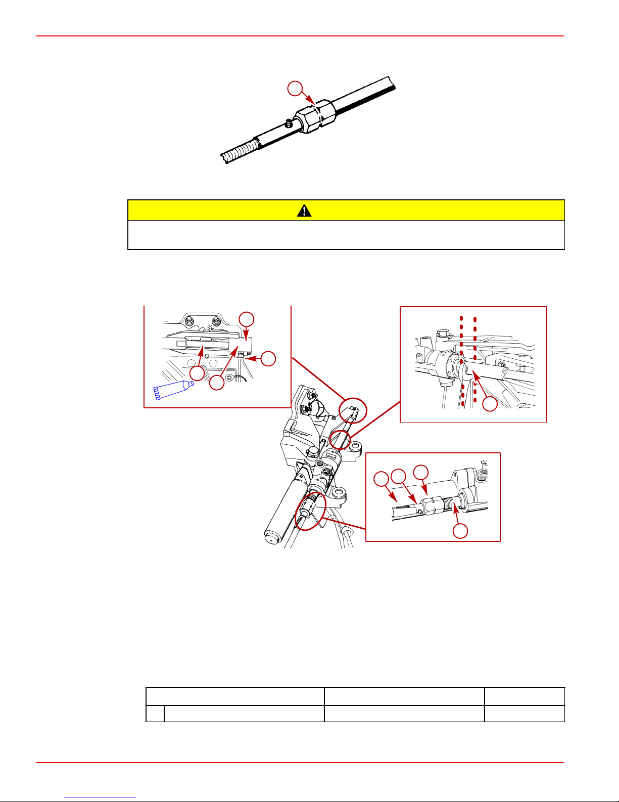
IMPORTANT: Quicksilver Ride Guide steering cable has a self-locking coupler nut
and does not require an external locking sleeve or locking plate.
a-Self-Locking Coupler Nut
Steering cable outer casing must be free to move back and forth for steering system
to function properly. Do not fasten any items to steering cable.
9. Coat steering cable end with a liberal amount of lubricant.
10. Install steering cable and secure with hardware.
a
22060
CAUTION
g
e
A
a-Steering Cable
b-Grease Fitting
c-Cable Coupler Nut
d-Cable Guide Tube
e-Steering Cable End
f-Clevis
g-Clevis Pin
h-Cotter Pin
f
h
71906
71901
d
73901
c
b
a
d
71903
Description
A Special Lubricant 101 Steering Cable End 92-13872A1
Page 28 of 137 90-860172011
Where Used Part Number
Page 29
GASOLINE STERNDRIVE INSTALLATION MANUAL
IMPORTANT: Slight feedback in the steering system could be encountered if the
cable guide tube flat surfaces are not positioned vertically.
1 1. Using a suitable wrench hold the flat surfaces on the cable guide tube in the vertical posi-
tion. Torque coupler nut. Be certain the flat surfaces are still aligned vertically after
torque is applied to coupler nut.
Description
Nm lb-in. lb-ft
Coupler Nut 47 35
CAUTION
Steering cable outer casing must be free to move back and forth for steering system
to function properly. Do not fasten any items to steering cable.
90-860172011 Page 29 of 137
Page 30
GASOLINE STERNDRIVE INSTALLATION MANUAL
MANUAL STEERING
1. Inspect bushings for debris. Lubricate bushings with Special Lubricant 101.
a
Manual Steering
a-Bushings
b-Special Lubricant 101
2. Remove shipping hardware.
3. Remove upper and lower pivot bolts and ensure threads are well lubricated with Special
Lubricant 101.
a
B
NOTICE to INSTALLER
22946
Refer to “Installation Requirements - Steering Helm and Cable” for steering cable
selection and coupler nut locking requirements.
4. Install steering assembly as follows:
a. Position steering assembly so that pivot bolts will enter bushings in pivot block or
power steering control valve.
b. Install upper and lower pivot bolts along with tab washers. Ensure that tab washer
tangs straddle the ridge on inner transom plate.
c. Turn pivot bolts all the way in by hand to ensure proper alignment.
d. Ensure steering assembly pivots freely.
5. Torque pivot bolts to 25 lb-ft (34 Nm). Bend washer tabs against corresponding flats on
bolt heads.
bc
a
Manual Steering
a-Tab Washers
b-Ridge
c-Pivot Bolts
NOTE: It may be necessary to tighten further to align flats on pivot bolt with tabs on tab
washer.
Page 30 of 137 90-860172011
22033
Page 31

GASOLINE STERNDRIVE INSTALLATION MANUAL
CAUTION
MOVING THE CONTROL VALVE RAM with the hoses disconnected will expel fluid
from the ports. Wear eye protection.
6. The cylinder ram may be stiff and difficult to move when you attempt to pull it out or push
it in for installation. First move the spool assembly in the direction(s) shown below.
a
a
74145
74144
a-Control Valve Ports
IMPORTANT: Newer style Quicksilver Ride Guide steering cable has a self-locking
coupler nut and does not require an external locking sleeve or locking plate.
a
a-Self-Locking Coupler Nut
90-860172011 Page 31 of 137
22060
Page 32

GASOLINE STERNDRIVE INSTALLATION MANUAL
Steering cable outer casing must be free to move back and forth for steering system
to function properly. Do not fasten any items to steering cable.
7. Connect steering cable as follows:
a. Remove shipping cap from both ends of steering cable guide tube or control valve
spool.
b. Coat steering cable end with a liberal amount of Special Lubricant 101.
c. Install steering cable and secure with hardware as shown on following pages.
Refer to “Installation Requirements - Steering Helm and Cable” for steering cable
selection and coupler nut locking requirements.
IMPORTANT: Slight feedback in the steering system could be encountered if the
cable guide tube flat surfaces are not positioned vertically.
CAUTION
NOTICE to INSTALLER
c
a
e
b
d
a-Steering Cable
b-Grease Fitting
c-Cotter Pin
d-Locking Sleeve (If Required - Must Be Ordered Separately)
e-Cable Coupler Nut
f-Cable Guide Tube
g-Steering Cable End
h-Cotter Pin
i-Clevis Pin
j-Steering Lever
f
50627
g
h
i
j
70018
50926
Page 32 of 137 90-860172011
Page 33

STEERING HELM AND CABLE
Transom assembly is shipped with the steering cable guide tube preset for cables with end
dimensions that comply with ABYC standards as outlined in the NMMA certification
handbook. The steering cable coupler nut must also have a means of locking it to the guide
tube, as specified in ABYC requirements.
Failure to use a steering cable locking device could cause loss of steering, which
could cause damage to the boat and/or injury.
NOTE: All current production Quicksilver RideGuide steering cables have a self-locking
coupler nut and do not require an external locking device. (Other cable manufacturers also
make cables with self-locking coupler nut.)
GASOLINE STERNDRIVE INSTALLATION MANUAL
WARNING
a
22060
a-Quicksilver RideGuide Steering Cable Self-Locking Coupler Nut (Identified By
Groove)
IMPORTANT: If using a steering cable that does not have a self-locking coupler nut,
an external locking device such as a locking sleeve must be used.
a
b
Example Of External Locking Device
a-Steering Cable
b-Locking Sleeve
CAUTION
If steering cable with improper dimensions is installed, severe damage to transom
assembly and/or steering system may result.
1. Steering cable must be the correct length, particularly when installed in larger boats.
2. Avoid sharp bends, kinks or loops in cable.
3. Fully extended steering cable end dimension must be as shown.
STEERING CABLE SPECIFICATIONS
IMPORTANT: Power steering pump lugging (squealing) in a hard right turn (against
lock) may mean a steering cable has been installed that does not have the correct
dimensions.
90-860172011 Page 33 of 137
Page 34

GASOLINE STERNDRIVE INSTALLATION MANUAL
a
c
b
e
f
k
j
l
a-Coupler Nut - 7/8 - 14 UNF - 28 Thread
b-11-3/4 in. (298 mm) Minimum
c-Interface Point
d-1/2 in. (12.7 mm) Maximum
e-27/64 in. (10.7 mm) Minimum Flat
f-7/64 in. (3.1 mm) Minimum Radius
g-5/8 in. (15.9 mm) Maximum Diameter End Fitting
h-3/8 in. (9.5 mm)
i-3/8 in. (9.8 mm) Diameter Through Hole (Chamfered Each Side)
j-1-3/8 in. (34.9 mm) Max
k-5/8 in. (15.9 mm) Diameter Tube
l-Cable Travel: Mid-Travel Position - 16-7/8 in. (429 mm)
Total Travel To Be 8 in. (203 mm) Minimum to 9 in. (228 mm) Maximum
Travel Each Side of Mid-Travel Position - 4 in. (102 mm) Minimum to
4-1/2 in. (114 mm) Maximum
d
g
C
L
h
i
21435
Page 34 of 137 90-860172011
Page 35

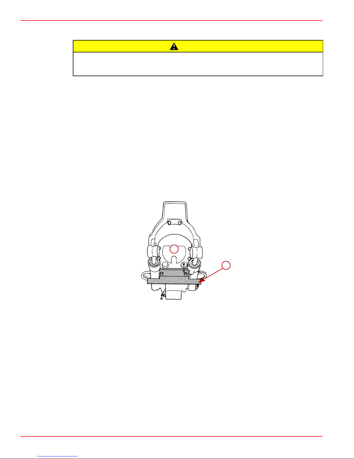
Transom Preparation
IMPORTANT: Exhaust pipe and gimbal housing mating surfaces must be clean and
free of nicks and scratches and O-ring must be properly seated in groove or water
and exhaust may leak into boat.
a-Gimbal Housing Mating Surface
b-O-ring
GASOLINE STERNDRIVE INSTALLATION MANUAL
a
b
22059
1. Ensure mating surfaces are clean and o-ring is properly seated.
2. Loosen hose clamps and remove exhaust pipe and bellows from engine.
c
c
b
b
a
3.0L Model V6 and V8 Models
a-Exhaust Pipe
b-Bellows
c-Clamps
d-Shipping Plug
75819
d
d
c
b
a
74768
90-860172011 Page 35 of 137
Page 36

GASOLINE STERNDRIVE INSTALLATION MANUAL
3. Through the Prop Exhaust Models: Install exhaust pipe assembly as shown, using
four bolts and lockwashers. Torque bolts.
b
a
50684
a-Exhaust Pipe
b-Bolts And Lockwashers (4)
Description
Bolts 31 23
4. Through the Transom Exhaust Models: Install block-off plate as shown, using four
bolts and lockwashers. Torque bolts.
Nm lb-in. lb-ft
a-Bolts And Lockwashers (4)
b-Block-Off Plate
Description
Bolts 31 23
NOTE: Through the Transom exhaust fittings can be installed at this time.
Page 36 of 137 90-860172011
a
b
22057
Nm lb-in. lb-ft
Page 37

GASOLINE STERNDRIVE INSTALLATION MANUAL
5. Position rear engine mount attaching hardware on inner transom plate mounts as
shown.
a
a
b
50634
22054
3.0L Models
a-Exhaust Pipe
b-Bolts and Lockwashers (4)
b
c
a-Fiber Washers
b-Double-Wound Lockwashers
c-Locknuts
a
50628
90-860172011 Page 37 of 137
Page 38

GASOLINE STERNDRIVE INSTALLATION MANUAL
BRAVO MODELS
IMPORTANT: When installing through the transom exhaust
, it is recommended that
the exhaust bellows on the transom assembly be removed. This is necessary to avoid
creating a vacuum at the exhaust outlet in the propeller at higher boat speeds. This
vacuum could degrade propeller performance on some boats.
1. If required, remove and discard clamps and bellows from gimbal housing.
IMPORTANT: When installing through the propeller exhaust
:
• With Bravo One and Bravo Two Sterndrives an exhaust tube MAY BE INSTALLED
for a slight increase in performance.
• With most Bravo Three Sterndrive Models an exhaust tube MAY BE INSTALLED
for a slight increase in performance.
• With a Silent Choice Exhaust System the exhaust bellows must be removed and
an exhaust tube MUST BE INSTALLED.
• With any application, installation of an exhaust tube will increase exhaust noise.
NOTE: Exhaust tube parts are provided with a Bravo Three Sterndrive. They are located
in the sterndrive unit box.
2. If required, install exhaust tube on gimbal housing as follows:
a. Remove and discard clamps and exhaust bellows.
CAUTION
Exhaust tube clamp may corrode if grounding clip is not installed.
b. Install grounding clip on tube.
NOTE: Bellows adhesive is not used when installing an exhaust tube.
c. Position tube so that “SIDE” markings on tube are facing toward the right and left
sides.
d. Install and torque the clamp.
e
d
c
b
a
a-Exhaust Tube
b-Clamp
c-SIDE Marking
d-Exhaust Tube
e-Grounding Clip
22184
Description
Clamp 4 35
Page 38 of 137 90-860172011
Nm lb-in. lb-ft
Page 39

Driveshaft Extension Models
If your power package is equipped with a driveshaft extension, refer to the Driveshaft
Extension Installation Instructions included with your engine package.
Engine Preparation
1. Remove and read all tags attached to engine.
2. Remove the plug from the engine coupler.
3. Remove all hardware that secures engine to shipping container.
4. Connect battery cables to engine. Be sure to observe the following:
a. Make sure that grounding stud and starter solenoid terminal are free of paint or any
other material that could cause a poor electrical connection.
b. After battery cables are connected, apply a thin coat of sealant to the terminals.
GASOLINE STERNDRIVE INSTALLATION MANUAL
Description
A Liquid Neoprene Battery Terminals 92-25711-2
c. Be sure to slide rubber boot over positive (+) terminal after making connection.
5. Drape battery cables over top of engine to prevent interference during installation.
IMPORTANT: There is a fuse located at the starter solenoid. DO NOT remove this fuse.
The positive battery cable must be connected to the same stud as the fuse.
Where Used Part Number
a
b
c
d
a-Positive (+) Battery Cable
b-Starter Solenoid
c-90 Amp Fuse - DO
d-Rubber Boot Location
NOT Remove
74907
6. Remove shipping plug from coupler and lubricate splines.
Description
A Engine Coupler Spline Grease Coupler Splines 92-816391A4
7. Install quick oil drain hose plug in oil drain hose.
8. Install the fuel inlet fitting.
90-860172011 Page 39 of 137
Where Used Part Number
Page 40

GASOLINE STERNDRIVE INSTALLATION MANUAL
Engine Installation
NOTE: An engine mount drilling fixture (91-806794A1) can be used to align and adjust
engine mounts. Refer to instructions with fixture for proper use.
1. Remove the engine cover.
2. Attach a suitable sling to lifting eyes on engine and adjust so that engine is level when
suspended.
Center lifting eye on top of thermostat housing is used for engine alignment only.
Do not use to lift entire engine.
CAUTION
a
CAUTION
!
3.0L Models
a-Center Lifting Eye
b-Engine Lifting Eyes
50636
b
b
50626
50632
b
a
b
!
CAUTION
V6 and V8 Models
a-Center Lifting Eye
b-Engine Lifting Eyes
3. Loosen the engine mount adjustment nut.
4. Lift engine into position in boat using an overhead hoist.
Page 40 of 137 90-860172011
74498
74760
74754
Page 41

GASOLINE STERNDRIVE INSTALLATION MANUAL
5. Line up the intermediate elbows with the exhaust tubes.
6. Spray lubricant into the exhaust tubes to assist with intermediate elbow installation into
exhaust tubes.
b
b
a
c
50635
3.0L Models Typical V6 And V8 Models
a-Bullhorn
b-Intermediate Elbow
c-Exhaust Tube
Description
Where Used Part Number
A Power Tune Exhaust Tubes 92-802878-57
7. If equipped with quick drain oil:
a. Push end of oil drain hose out of boat hull through flange.
b. Pull oil drain hose out until it is 6 in. (152 mm) from the propeller.
50682
c
A
c. Move alignment clip on the oil drain hose and squeeze to position it on the hose just
inside of the boat hull against the flange.
d. Connect bilge drain plug to oil drain hose plug using clip.
b
d
c
a
78002
a-Oil Drain Hose
b-Alignment Clip
c-Clip
d-Bilge Drain Plug
90-860172011 Page 41 of 137
Page 42

GASOLINE STERNDRIVE INSTALLATION MANUAL
e. Push oil drain hose through flange into boat hull.
f. Install bilge drain plug in hull.
8. Align rear engine mounts with inner transom plate mounts while simultaneously aligning
exhaust tube with intermediate elbows.
9. Install both rear engine mounting bolts and hardware and torque. Do not relieve hoist
tension.
c
d
e
a
g
f
b
a-Rear Engine Mount
b-Inner Transom Plate Mount
c-Bolt
d-Washer
e-Spacer
f-Fiber Washer
g-Double-Wound Lockwasher
Description Nm lb-in. lb-ft
Rear Engine Mounting Bolts 51 38
72535
IMPORTANT: If quick drain oil fitting is within 1/2 in. (6 mm) of boat bottom, remove
fitting and install drain plug from parts bag directly into oil pan.
10. Ensure quick drain oil fitting is more than 1/2 in. (6 mm) above the boat bottom.
Page 42 of 137 90-860172011
Page 43

Exhaust System
It is the responsibility of the boat manufacturer or installing dealer to properly locate the engine and install the exhaust system. Improper installation may allow water to enter the exhaust manifolds and combustion chambers and severely damage
the engine. Damaged caused by the water in the engine will not be covered by Mercury MerCruiser Warranty, unless this damage is the result of defective parts.
MEASURING PROCEDURE
1. Fill all fuel, water, gray water and heater tanks to maximum capacity.
NOTE: Weight can be added in these locations to simulate full loaded condition.
2. Add maximum allowable cargo weight to boat in areas where it will be stowed, including
refrigerator and lockers.
3. Add 190 lb (86 kg) of weight in all locations where each passenger will sit during normal
operation.
4. Measure exhaust elbow height. Also, measure exhaust system slope on applications
with through the hull or through the transom exhaust.
GASOLINE STERNDRIVE INSTALLATION MANUAL
CAUTION
a
b
Using A Universal Protractor (Inclinometer) To Measure Slope
a-Protractor
b-Exhaust Hose Or Tube
77981
90-860172011 Page 43 of 137
Page 44

GASOLINE STERNDRIVE INSTALLATION MANUAL
5. On applications with through the propeller exhaust: Proceed to Step 7.
6. On applications with through the hull or through the transom exhaust:
a. Move load weight to bow to simulate greatest bow-down attitude the boat will
encounter in normal operation.
b. Recheck exhaust system slope.
7. Move load weight and cargo weight to stern of boat to stimulate greatest stern-down
attitude the boat will encounter such as when loading.
IMPORTANT: Be sure to consider swim platform loading and personal watercraft.
8. Recheck exhaust system measurements.
Minimum Exhaust Elbow Height from Top of Elbow to Waterline
Model Measurement
All V6 and V8 13 in. (330 mm)
a
b
13 [330]
c
d
a-Top Of Transom
b-Highest Point On Exhaust Elbow
c-Measurement
d-Waterline
Additional requirements for through the hull or transom exhaust system applications:
Minimum Continuous Downward Slope (Exhaust Hoses, Collector, Etc.)
Model Measurement (degrees)
All Sterndrive 6
70082
77956
Page 44 of 137 90-860172011
Page 45

GASOLINE STERNDRIVE INSTALLATION MANUAL
9. If measurements are less than specified, exhaust elbow risers must be installed to
achieve proper dimension.
a
b
c
d
e
77991
Typical Riser Installation
a-Exhaust Elbow
b-Restrictor Gasket
c-Riser
d-Open Gasket (4 Slots)
e-Exhaust Manifold
NOTE: Up to a maximum of 9 in. (229 mm) of riser height can be added.
90-860172011 Page 45 of 137
Page 46

GASOLINE STERNDRIVE INSTALLATION MANUAL
Methods for Measuring Exhaust Elbow Height
STRAIGHT EDGE METHOD
1. Place a straight edge across boat.
2. With the straight edge above the engine as shown, measure the distance between the
straight edge and the top of the exhaust elbow.
3. Make sure that the boat is level from side-to-side, using a level or inclinometer. Then,
measure the distance between the straight edge and the outside waterline.
4. The dif ference between these two measurements is the exhaust elbow height above the
water line. Refer to Measuring Procedures and compare measurement to
specifications.
c
b
d
a
a-Waterline
b-Top Of Exhaust Elbow
c-Straight Edge
d-Measurement Between Straight Edge And Top Of Exhaust Elbow
e-Measurement Between Straight Edge And Water Line
e
76859
72700
Page 46 of 137 90-860172011
Page 47

CLEAR HOSE METHOD
1. Obtain a 5/16 - 3/8 in. (8-10 mm) long hose approximately 15 ft. (4.5 m) long. Put a metal
fitting or a weight on one end of the hose to keep that end of the hose below the water
line.
2. Put the weighted end of the hose over the port or starboard side of the boat, keeping
it in line with the engine’s exhaust elbow.
3. Route the remainder of the hose toward the engine’s exhaust manifold and elbow.
Ensure that this open end section of the hose is as vertical as possible from the boat’s
bilge to the top of the exhaust elbow
4. Coil excess hose in bilge of boat, keeping it below the water line.
5. Lower open end of hose and siphon water until it starts to come out of the hose. Put a
finger over the hose and lift open end until it is at the top of the exhaust elbow.
6. Slowly take finger off end of hose to let the water level stabilize. The water will seek the
level of the water outside the boat. Keep hose close to exhaust elbow and as vertical
as possible.
7. Make sure that the boat is level (side-to-side) using a level or inclinometer.
8. The measurement between water in hose and top of exhaust elbow is the exhaust elbow
height.
GASOLINE STERNDRIVE INSTALLATION MANUAL
b
a
a
a-Waterline
b-Top Of Exhaust Elbow
c-Clear Plastic Hose
d-Weight
e-Measurement - Waterline To Top Of Exhaust Elbow
c
e
76859
d
72700
90-860172011 Page 47 of 137
Page 48

GASOLINE STERNDRIVE INSTALLATION MANUAL
Exhaust System Hose / Tube Connections
Avoid exhaust hose failure. Discharge water from exhaust elbow must flow around
entire inside diameter of hose to avoid causing hot spots which could eventually
result in burned-through exhaust hoses. Exhaust hoses and/or tubes must be correctly connected to exhaust elbows so that they do not restrict the flow of discharge
water from exhaust elbow.
Correct Connection Incorrect Connection
IMPORTANT: Exhaust hoses/tubes should be secured at each connection with at
least 2 hose clamps.
1. Tighten all exhaust hose and/or exhaust tube clamps securely.
CAUTION
71653
a-Hose Clamps
a
73961
Page 48 of 137 90-860172011
Page 49

Engine Alignment
1. Ensure that the dust cover is removed or folded back out of the way.
GASOLINE STERNDRIVE INSTALLATION MANUAL
a
22027
a-Dust Cover
CAUTION
DO NOT use an alignment tool from another manufacturer. Alignment tools other
than Quicksilver Alignment Tool may cause improper alignment and damage to
gimbal bearing and/or engine coupler.
2. Attempt to insert the solid end of the alignment tool through the gimbal bearing and into
the engine coupler splines.
3. If the tool does not fit, remove it and carefully raise or lower the front end of the engine
using the center alignment eye and attempt to insert the alignment tool.
90-860172011 Page 49 of 137
Page 50

GASOLINE STERNDRIVE INSTALLATION MANUAL
4. Repeat step 3. until the alignment tool installs easily (SLIDES FREELY WITH TWO
FINGERS) all the way into and out of engine coupler splines. Do not check by turning
the alignment tool.
a-Alignment Tool (Use Only Recommended Alignment Tool)
b-Insert This End Of Alignment Tool Through Gimbal Housing Assembly
b
a
22029
a-Alignment Tool
b-Gimbal Bearing
c-Engine Coupler
c
b
a
27647
Page 50 of 137 90-860172011
Page 51

GASOLINE STERNDRIVE INSTALLATION MANUAL
IMPORT ANT: Finished boat stringer must position engine so that a minimum mount
adjustment exists after front mount is adjusted down to stringer. This allows for
future adjustments.
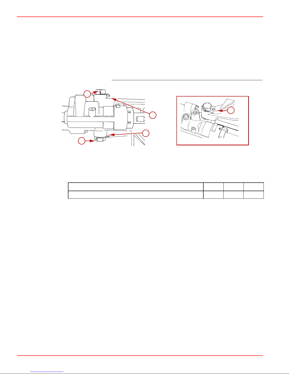
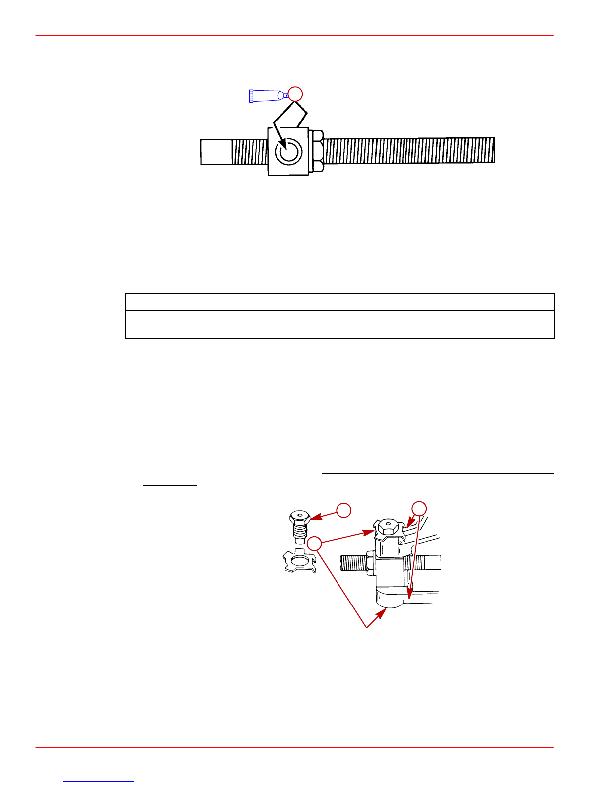
5. 3.0L Center Mount Model:
a. Set the engine on the stringer.
b. Relieve the hoist tension.
c. Attach the hoist to the center alignment eye.
d. Fasten front mount to the stringer.
e. Recheck alignment.
f. Tighten locknut and jam nut securely.
c
a
b
3.0L Center Mount Model
a-Front Mount
b-Attaching Bolts and Flat Washers
c-Adjusting Nut
d-Locknut
e-Jam Nut
e
d
b
22054
90-860172011 Page 51 of 137
Page 52

GASOLINE STERNDRIVE INSTALLATION MANUAL
IMPORTANT: Turn both front engine mount adjustment nuts an equal amount in
direction required to align engine.
6. All Other Models:
a. Adjust front engine mounts until they rest on boat stringers.
b. Relieve hoist tension entirely and fasten both front mounts to boat stringer using ap-
propriate hardware.
c. Tighten the bottom nut to hold the engine in place. Then release the tension.
b
c
d
a
a
3.0L Side Mount Model
a-Engine Mount
b-Bolt
c-Lockwasher
d-Tab Washer
V6 and V8 Models
a-Engine Mount
b-Bottom Nut - Not Visible
c-Tab
77968
77970
a
b
c
77913
Page 52 of 137 90-860172011
Page 53

7. Recheck alignment with alignment tool. Tool must enter coupling splines freely. If not,
readjust front mounts.
8. When alignment is correct, tighten locknut securely. Recheck alignment.
9. Bend tab down on adjusting nut.
10. Remove alignment tool. If not installing drive, fold bell housing dust cover flap back into
place and tape shut for boat shipment. Dust cover flap will have to be removed before
operating engine.
11. Hook up the ground stud.
12. Connect the trim pump sender wires.
13. Install the water inlet hose onto the transom.
Hot Water Heater Installation
IMPORTANT: When connecting a cabin heater or hot water heater:
• Supply hose (from engine to heater) and return hose (from heater to engine)
MUST NOT EXCEED 5/8 in. (16 mm) inside diameter (ID).
• Make heater connections ONLY at locations shown.
• Refer to manufacturers’ instructions for complete installation information and
procedures.
GASOLINE STERNDRIVE INSTALLATION MANUAL
• Do not reposition engine temperature switch.
Avoid a performance loss and/or possible engine damage. Engine coolant must
flow continuously from the engine intake manifold to the engine water circulating
pump. NEVER close-off or block the coolant flow to or from a heater.
Avoid engine overheating which could result in engine damage. On models
equipped with Closed Cooling, an air pocket may form in the closed cooling system
if some coolant is lost from the system and the cabin heater or hot water is mounted
higher than the fill cap on the heat exchanger. Heater must be mounted lower
the fill cap of the heat exchanger on models so equipped.
SUPPLY HOSE CONNECTION
CAUTION
CAUTION
than
3.0L
a-Location For Hot Water Supply (Install Bayonet Fitting Here)
90-860172011 Page 53 of 137
a
76095
Page 54

GASOLINE STERNDRIVE INSTALLATION MANUAL
a
75473
Seawater Cooling - If Location Is Available
a-Location For Hot Water Supply
a
Seawater Cooling - Alternate Location
a-Location For Hot Water Supply
a
74973
71758
b
a
b
74639
Closed Cooling Models - If Location Is Available
a-Location for Hot Water Supply (Bayonet Fitting Replaces Brass Plug)
b-Thermostat Housing
a
Page 54 of 137 90-860172011
Page 55

RETURN HOSE CONNECTION
Typical 3.0L
a-Location For Hot Water Return (T-Fitting Installed in Water Circulating Pump
Hose)
GASOLINE STERNDRIVE INSTALLATION MANUAL
a
73572
a
Seawater or Closed Cooling System
a-Location For Hot Water Return
Electrical Connections
IMPORTANT: When routing all wire harnesses and hoses, be sure they are routed and
secured to avoid coming in contact with hot spots on engine and to avoid contact
with moving parts.
Installing Continuity Wire
1. Connect continuity circuit wire from engine to transom assembly.
IMPORT ANT: Do not attach any accessory ground (–) wires to transom plate ground
point. Accessory ground wires can only be attached to ground stud on engine.
75480
a-Continuity Wire
90-860172011 Page 55 of 137
a
71651
Page 56

GASOLINE STERNDRIVE INSTALLATION MANUAL
Instrumentation Connections
We recommend the use of Quicksilver Instrumentation and Wiring Harnesses. On dual station applications, oil pressure and water temperature senders (on engine) must be changed.
Refer to Mercury Precision Parts / Quicksilver Accessories Guide for selection.
The 4 basic gauges that must be used with the engine are:
• Tachometer
• Oil Pressure
• Water Temperature
• Voltmeter
IMPORT ANT: Connect fused accessory panel (40-amp current draw maximum) must
be connected as shown in the wiring diagrams.
1. Route instrumentation wiring harness back to engine, making sure that harness does
not rub or get pinched. If an extension harness is required, be sure to secure connection
properly.
2. Fasten harnesses to boat at least every 18 in. (460 mm), using appropriate fasteners.
3. Place hose clamp over instrumentation wiring harness.
4. Connect the instrumentation wiring harness to engine harness plug at location shown.
a
Typical
a-Wiring Harness Connector
5. Tighten hose clamp to secure wiring harness to engine harness plug.
74754
Page 56 of 137 90-860172011
Page 57

Trim Position Sender Connections
1. Connect trim position sender wires (from transom assembly) to engine harness.
GASOLINE STERNDRIVE INSTALLATION MANUAL
a
b
a
ORG/WHT
BLK
a-Engine Harness Bullet Connector
b-Transom Assembly Bullet Connector
MerCathode Connections (If Equipped)
1. Connect wires to MerCathode controller assembly as shown. Apply a thin coat of Liquid
Neoprene to all connections.
IMPORTANT: Opposite end of RED/PURPLE wire must be connected directly to
battery positive (+) terminal. DO NOT connect it to a switched positive (+) circuit.
MerCathode system must function continuously for proper corrosion protection.
BLK
BLK
b
74029
a-ORANGE Lead - From Electrode On Transom Assembly
b-RED/PURPLE Wire - To Positive (+) Battery Terminal
c-BLACK Wire - From Engine Harness
d-BROWN Wire - From Electrode On Transom Assembly
Description Where Used Part Number
A Liquid Neoprene MerCathode Connections 92-25711-2
90-860172011 Page 57 of 137
a
c
b
d
22232
Page 58

GASOLINE STERNDRIVE INSTALLATION MANUAL
Audio Warning System Connections
Alarm is not external ignition-proof, therefore, DO NOT mount alarm in engine or
fuel tank compartments.
1. Select a location for audio warning alarm which meets all of the following:
• alarm can be easily heard, yet is out of sight
• alarm can be easily accessed for installation and maintenance
• alarm will remain dry
• alarm is within length limits of the 18 in. purple alarm wire that connects to the “I” terminal
or 12 volt source on switched side of ignition switch.
NOTE: The terminal to which wire is attached must have no voltage when ignition switch
is in the OFF position.
2. Place alarm in desired location and secure to wire bundle with tie-strap provided.
3. Connect PURPLE wire from alarm to any PURPLE wire terminal on instrument gauge
or ignition switch. Tighten connection securely.
4. Connect TAN/BLUE wire from alarm to TAN/ BLUE wire from instrument harness.
WARNING
5. Place the small (transparent) decals on the bottom of the water temperature and the oil
pressure gauges.
6. Place the large decal on the instrument panel or other appropriate location in easily
viewed by the operator.
ALARM INDICATES LOW
OIL OR OVERHEATING
a
APPLY THE PROPER DECAL TO THE DASHBOARD
OR OTHER APPROPRIATE LOCATION:
AUDIO WARNING HORN WILL SOUND WHEN:
1. ENGINE OIL PRESSURE IS TOO LOW
2. ENGINE TEMP. IS TOO HIGH, OR
3. DRIVE OIL LEVEL IS TOO LOW
TO TEST AUDIO WARNING HORN:
TURN KEY TO “ON” POSITION (ENGINE OFF)
b
75430
a-Small Decal (Transparent)
b-Larger Decal
7. Test audio warning system during Predelivery Preparation section.
Page 58 of 137 90-860172011
Page 59

Power Trim Pump Connections
IMPORT ANT: Make hydraulic connections as quickly as possible to prevent oil from
leaking out of system. Be careful not to cross-thread or overtighten hose fittings.
1. Connect hydraulic hoses to trim pump. Torque fittings.
GASOLINE STERNDRIVE INSTALLATION MANUAL
Description
Nm lb-in. lb-ft
Fittings 14 125
2. Connect power trim pump control harness to trim pump.
3. Connect trim limit switch wires and secure with wire retainer and tie-strap.
d
c
75126
75127
b
f
g
a
50630
e
a-Black Hose Fitting (UP Circuit)
b-Gray Hose Fitting (DOWN Circuit)
c-Control Harness
d-Tie-Strap
e-Trim Limit Switch Wire (With Blue Sleeve) To BLUE/WHITE Harness Wire
f-Trim Limit Switch Wire (With Purple Sleeve) To PURPLE/WHITE Harness Wire
g-Wire Retainer And Tie Strap
50632
90-860172011 Page 59 of 137
Page 60

GASOLINE STERNDRIVE INSTALLATION MANUAL
4. Unscrew fill cap and remove cap plug from fill neck and discard. Install fill cap.
a-Caplug
b-Fill Cap
5. Connect power trim pump wires to battery.
a
a
b
50630
b
a-Positive Battery Lead
b-Negative Battery Lead
76631
Page 60 of 137 90-860172011
Page 61

Fluid Connections
Gear Lube Monitor Hose
IMPORT ANT: A void using excessive hose when routing it to gear lube monitor. Hose
should be routed directly to oil reservoir in as straight a line as possible to avoid low
spots (traps) in the system.
Ensure hose is not kinked when connecting in the following step. If hose is kinked,
gear lube monitor will not function properly and damage to drive unit could occur.
1. Route hose to gear lube monitor and cut off excess hose. Hose can be routed on outside
of remote oil filter or the hole in the front lifting eye bracket.
2. Connect hose and secure with hose clamp.
IMPORTANT: Hose must not come in contact with steering system components or the
engine coupler, U-joint shaft or drive shaft.
GASOLINE STERNDRIVE INSTALLATION MANUAL
CAUTION
a
b
c
71983
181 CID/3.0L Model Typical
a-Gear Lube Monitor
b-Hose
c-Clamp
d-Sta-Strap
3. Use extra hose clips to secure hose to transom.
d
a
77108
90-860172011 Page 61 of 137
Page 62

GASOLINE STERNDRIVE INSTALLATION MANUAL
Power Steering Hoses
Route hoses exactly as shown below. This will help avoid stress on the hose fittings
and will help avoid kinks in the hose.
IMPORTANT: Make hydraulic connections as quickly as possible to prevent fluid
leakage.
IMPORTANT: Be careful not to cross-thread or overtighten fittings.
1. Route hoses. Secure hoses to avoid contact with moving components.
2. Connect power steering hoses to control valve. Torque both fittings.
CAUTION
Description
Fittings 31 23
3. Use extra hose clips to secure hose to transom.
NOTE: Power Steering Fluid can be added at this point, if desired.
Nm lb-in. lb-ft
Bravo Models and Alpha Seawater Cooled Models Using Sterndrive Water
Pickups
1. Connect water hose to water inlet fitting.
2. Secure with hose clamp.
c
b
a-Water Inlet Fitting
b-Hose
c-Hose Clamp
a
72040
Page 62 of 137 90-860172011
Page 63

GASOLINE STERNDRIVE INSTALLATION MANUAL
Alpha or Bravo Models Using Alternative Water Pickups
A water inlet block-off kit must be used if the sterndrive unit water pickup will not be used
to supply water to the engine. When installing the block-off plate, it is necessary to cut the
water hose that is located between the bell housing and the gimbal housing. This allows
water to continue to circulate through the sterndrive unit for cooling.
CAUTION
Avoid overheating sterndrive. The seawater inlet holes must be allowed to flow
water without being obstructed or overheating damage to sterndrive may result. Do
not dead-end seawater hose from bell housing. Cut hose as recommended in
procedures.
1. Remove the existing water fitting and gasket. Discard the screws and washers.
a
b
50663
a-Water Fitting
b-Screws And Lockwashers
2. Remove the tapered insert in the gimbal housing using the tapered insert tool
(91-43579). Discard the insert.
c
a
a
b
22080
a-Tapered Insert
b-Tapered Insert Tool
c-Gimbal Housing Cross-Sectional View
22101
Tapered Insert Tool 91-43579
90-860172011 Page 63 of 137
Description
Part Number
Page 64

GASOLINE STERNDRIVE INSTALLATION MANUAL
3. Install the block-off plate with new gasket. Secure with screws and lockwashers. Torque
the screws.
a
d
c
1
b
75314
75313
a-Block-Off Plate
b-Gasket
c-Screw
d-Lockwasher
Description
Nm lb-in. lb-ft
1 Screw, Water Fitting 5 45
4. Move the trim limit switch wires and speedometer hose aside. Reach between the
gimbal housing and the bell housing and detach the water hose from the gimbal housing
where the tapered insert was removed in Step 2.
a
d
b
a-Trim Limit Switch Wires
b-Speedometer Hose
c-Gimbal Housing
d-Water Hose
e-Tapered Insert
71184
e
c
22101
Page 64 of 137 90-860172011
Page 65

GASOLINE STERNDRIVE INSTALLATION MANUAL
WARNING
Avoid water leakage into boat. Damage to U-joint bellows could result in water
entering the boat. Do not damage the U-joint bellows when removing a section of
the water hose attached between the gimbal housing and bell housing.
NOTE: Move the trim limit switch wires and speedometer hose to avoid damaging them
when cutting the water hose. The existing tie strap and clip can be reused if they are moved
and repositioned after the hose is cut.
5. Cut completely through the water hose 5 in. (127 mm) in front of the aft end of the hose
where it is fitted into the bell housing. in the area shown. DO NOT damage the U-joint
bellows. Discard loose hose piece.
6. Secure the trim limit switch wires and speedometer hose to the remaining section of
water hose using existing tie strap and clip.
e
e
c
c
a-Tie Strap
b-Clip
c-Water Inlet Hose
d-Speedometer Hose
e-Trim Limit Wire Harness
f-Cutting Area
f
f
b
b
a
a
d
d
71184
90-860172011 Page 65 of 137
Page 66

GASOLINE STERNDRIVE INSTALLATION MANUAL
Coolant Recovery System
Avoid engine overheating and subsequent damage to engine. The coolant recovery
system will not operate properly without proper sealing. Plastic tubing MUST seal
completely at connections.
1. Connect plastic tubing to bayonet fitting on heat exchanger. Secure with tubing clamp
provided.
CAUTION
b
a
70548
a-Plastic Tubing
b-Tubing Clamp
1. Remove cap from coolant recovery reservoir and fill to FULL mark with coolant solution.
2. Reinstall cap.
Page 66 of 137 90-860172011
Page 67

Shift Cable Installation
Alpha Models - Drive Unit Not Installed
We recommend the use of a Quicksilver remote control and cable. Refer to Mercury
Precision Parts / Quicksilver Accessories Guide for selection. However, if a control other
than Quicksilver is to be used, control must provide a shift cable travel (at the shift plate end)
of 2-7/8 in. (73 mm) to 3-1/8 in. (80 mm) with a 15-20 lb. (6.8-9 kg) load applied to the cable
end guide.
NOTE: On engines with Alpha drives, the measurement indicated above can be taken by
installing the remote control shift cable and using the shift assist assembly (provided) to
place the proper load on the shift cable.
1. Place a mark on the tube against the edge of the cable end guide.
d
GASOLINE STERNDRIVE INSTALLATION MANUAL
e
a
a
b
a-Shift Assist Assembly
b-Remote Control Shift Cable - In FORWARD Gear Position
c-Edge Of Cable End Guide
d-Remote Control Shift Cable - In REVERSE Gear Position
e-Measurement Taken From Mark To Edge Of Cable End Guide:
2-7/8 in. (73 mm) to 3-1/8 in. (80 mm)
c
a
50368
90-860172011 Page 67 of 137
Page 68

GASOLINE STERNDRIVE INSTALLATION MANUAL
IMPORTANT: If boat is being equipped with a REMOTE CONTROL THAT HAS
SEPARATE SHIFT AND THROTTLE LEVERS, the shift assist assembly that is shipped
with the engine should NOT be used. The use of the shift assist assembly with this
type of remote control can cause the shift lever to move out of gear unexpectedly.
The following kit will have to be ordered to connect remote control shift cable when shift
assist assembly is not used.
Spacer Kit 23-11284A1
a
d
b
c
a-Clevis Pin
b-Washer
c-Spacer
d-Cotter Pin
NOTE: Do not discard shift assist assembly until after it is used in step 3., following.
IMPORTANT: Shift cable must be connected at the remote control for the appropriate
rotation (LH or RH) drive unit, as explained following:
RIGHT HAND ROTATION - Control cable will have to be installed in remote control so that
cable end will move in direction “A” when shift handle is placed in the FORW ARD position.
LEFT HAND ROTATION - Control cable will have to be installed in remote control so that
cable end will move in direction “B” when shift handle is placed in the FORWARD position.
50310
A
B
71656
Page 68 of 137 90-860172011
Page 69

GASOLINE STERNDRIVE INSTALLATION MANUAL
IMPORTANT: Use the following procedure to temporarily install shift cables if boat
will be shipped without drive unit installed. Refer to Shift Cable Installation for shift
cable adjustment procedure once drive unit is installed.
1. Remove shift cable attaching hardware.
c
a
b
50308
a-Cotter Pin
b-Clevis Pin And Cotter Pin
c-Washer And Locknut
2. Place remote control shift lever in NEUTRAL position.
3. Temporarily install clevis pin through remote control shift cable end guide, shift assist
assembly end and into hole in shift lever . Then adjust brass barrel so that hole in barrel
aligns with anchor stud.
c
d
a
a-Clevis Pin
b-Shift Cable End Guide
c-Shift Assist Assembly End
d-Shift Lever
e-Brass Barrel (On Stud)
e
b
50308
90-860172011 Page 69 of 137
Page 70

GASOLINE STERNDRIVE INSTALLATION MANUAL
4. Remove remote control shift cable and shift assist assembly.
IMPORTANT: Install the cotter pin through the top of the barrel retainer.
5. Install drive unit shift cable as shown. Secure brass barrel in barrel retainer with cotter
pin and spread both prongs.
of end guide) and locknut. Tighten locknut until it contacts, then loosen 1/2 turn
Without Shift Assist Assembly
a-Cotter Pin
b-Locknut And Washers
Secure cable end guide with washers (one on each side
.
b
a
75415
Page 70 of 137 90-860172011
Page 71

GASOLINE STERNDRIVE INSTALLATION MANUAL
6. Install remote control shift cable (with or without shift assist assembly as applicable) and
secure with hardware as shown. Tighten locknut finger tight only and do not spread
cotter pin completely. (Remote control shift cable fasteners will have to be removed
again to properly adjust shift cables under Shift Cable Installation section of this
manual.)
c
With Shift Assist Assembly
a-Remote Control Shift Cable
b-Shift Assist Assembly
c-Clevis Pin And Cotter Pin
d-Large I.D. Washer
e-Small I.D. Washer And Locknut
c
a
d
e
b
50308
a
b
Without Shift Assist Assembly
a-Remote Control Shift Cable
b-Pin
c-Cotter Pin (Existing)
d-Spring (Existing)
e-Washer (Existing)
f-Washer
g-Spacer
h-Washer (Existing)
i-Locknut (Existing)
d
e
g
h
i
f
50310
90-860172011 Page 71 of 137
Page 72

GASOLINE STERNDRIVE INSTALLATION MANUAL
Bravo Models
NOTE: Using Adjustment Tool (91-12427), shift cables can be adjusted without or with the
sterndrive installed, using the following procedure.
IMPORTANT: Sterndrive unit propeller rotation is determined by the shift cable
installation in the remote control.
• Bravo One/Two
is placed in FORWARD, remote control is set up for RIGHT HAND (RH) propeller
rotation.
• Bravo One/Two
is placed in FORWARD, remote control is set up for LEFT HAND (LH) propeller
rotation.
- If shift cable end guide moves in direction A when control lever
- If shift cable end guide moves in direction B when control lever
A
B
71656
Arrow Indicates Direction Of Motion
• Bravo Three - Front propeller on sterndrive unit is always LH Rotation and rear
propeller is always RH Rotation. Shift cable end guide must move in direction A,
when control lever is placed in FORWARD gear position.
A
71656
IMPORTANT: When installing shift cables, be sure that cables are routed in such a
way as to avoid sharp bends and/or contact with moving parts. DO NOT fasten any
items to shift cables.
1. Install shift cable into remote control. (Refer to appropriate remote control instructions.)
2. Remove the guide.
3. Loosen stud and move it to dimension, as shown. Retighten stud.
a
b
71657
a-Stud
b-3 in. (76 mm) (Center Of Pivot Bolt To Center Of Stud)
Page 72 of 137 90-860172011
Page 73

GASOLINE STERNDRIVE INSTALLATION MANUAL
4. Install sterndrive unit shift cable.
5. Tighten locknut until it contacts and then loosen 1/2 turn.
6. Insert cotter pin from top and spread ends.
b
c
a
71658
a-Washers (2)
b-Locknut
c-Cotter Pin
7. Place adjustment tool over sterndrive unit shift cable, as shown. Hold tool in place, using
a piece of tape over the barrel retainer.
71659
8. Locate center of remote control and control cable play (backlash).
IMPORTANT: Be sure to keep center mark “c” aligned with control cable end guide
edge when making the following adjustment.
a. Shift remote control to NEUTRAL.
b. Push in on control cable end with enough pressure to remove play and mark position
“a” on tube.
c. Pull out on control cable end with enough pressure to remove play and mark position
“b” on tube.
d. Measure distance between marks “a” and “b” and mark position “c” half-way
between marks “a” and “b.”
c
a
b
90-860172011 Page 73 of 137
71656
Page 74

GASOLINE STERNDRIVE INSTALLATION MANUAL
9. Temporarily install control cable end guide into shift lever and insert anchor pin.
10. Adjust control cable barrel so that hole in barrel centers with vertical centerline of stud.
Ensure that backlash center mark is aligned with edge of control cable end guide.
DO NOT attempt to install or remove control cable barrel from stud without first removing end guide anchor pin from shift lever and removing cable. Attempting to
bend control cable to install or remove barrel will place undue stress on cable end
guide and shift lever and damage to both could occur.
11. Remove control cable end guide from shift lever by removing anchor pin.
CAUTION
b
a
c
a-Control Cable End Guide
b-Anchor Pin
c-Backlash Center
d-Control Cable Barrel
e-Stud
12. Install control cable.
13. Install washer and locknut.
14. Tighten locknut until it contacts and then loosen 1/2 turn.
15. Insert cotter pin from top and spread ends.
d
e
71660
a-Locknut
b-Washers - Both Sides Of Barrel
c-Anchor Pin
d-Cotter Pin (Not Shown)
Page 74 of 137 90-860172011
c
b
a
71661
Page 75

GASOLINE STERNDRIVE INSTALLATION MANUAL
16. Remove adjustment tool.
17. Shift remote control lever into full FORWARD position. Place end of adjustment tool in
barrel retainer.
RH rotation Bravo One, Two and Three Models: Rear slot in tool should fit over shift lever
stud.
LH rotation Bravo One And Two: Forward slot in tool should fit over shift lever stud.
If slot does not fit over stud, loosen shift lever stud and slide stud up or down until slot in tool
fits over stud. When adjustment is correct, retighten stud.
RH Rotation Bravo One, Two, Three
c
LH Rotation Bravo One And Two
a-Adjustment Tool
b-Barrel Retainer
c-Shift Lever Stud
d-Shift Lever Adjustment Slot
c
a
b
71662
d
a
b
71663
18. Remove adjustment tool.
19. Lubricate shift cable pivot points.
Description
SAE 30W Engine Oil Shift Cable Pivot Points Obtain Locally
90-860172011 Page 75 of 137
Where Used Part Number
Page 76

GASOLINE STERNDRIVE INSTALLATION MANUAL
Throttle Cable Installation and Adjustment
1. Place remote control handle(s) in neutral/idle position.
IMPORTANT: Be sure that cable is routed to avoid sharp bends and/or contact with
moving parts. DO NOT fasten any items to throttle cable. Outer cable must be free to
move when cable is actuated.
2. Adjust cable so that it can be placed on both studs simultaneously.
3. Place cable over studs. DO NOT adjust cable after installation.
4. Secure throttle cable with hardware as shown. DO NOT overtighten as cable must pivot
freely. Tighten until nut contacts, then loosen 1/2 turn.
5. Place remote control throttle lever in the wide open throttle (WOT) position. Ensure that
throttle shutters are completely open.
6. Return remote control throttle lever to idle position and ensure that throttle lever contacts
idle speed adjustment screw.
g
e
d
f
c
b
2 BBL V6 and V8 Models
a-Cable End Guide
b-Throttle Lever Screw
c-Locknut and Flat Washer (Small)
d-Throttle Lever
e-Idle Speed Adjustment Screw
f-Idle Cam
g-Throttle Bracket
h-Cable Barrel
i-Flat Washer and Locknut (Large)
j-Throttle Cable Anchor Stud
h
a
i
j
76900
Page 76 of 137 90-860172011
Page 77

Sterndrive Unit Installation
1. Remove trim cylinder support and dust cover from bell housing studs. (Retain elastic
stop nuts and flat washers.)
2. Remove gear lube monitor cap. Fill with lubricant.
a-Gear Lube Monitor
GASOLINE STERNDRIVE INSTALLATION MANUAL
a
77108
Description
Where Used Part Number
A High Performance Gear Lube Gear Lube Monitor 92-802853A1
3. Push dribble valve stem in until gear lube appears.
a
75531
a-Dribble Valve Stem
4. Once gear lube appears, release dribble valve stem.
5. Fill monitor to FULL mark.
6. Replace monitor cap.
90-860172011 Page 77 of 137
Page 78

GASOLINE STERNDRIVE INSTALLATION MANUAL
IMPORTANT: Rubber gasket must be properly positioned in bell housing bore before
installing drive unit or water may leak into boat.
7. Alpha Models: Ensure that rubber gasket and water passage O-ring are properly
positioned in bell housing.
a
b
75531
a-Rubber Gasket
b-Water Passage O-ring
8. Coat sterndrive unit pilot, U-joint O-rings and drive shaft splines.
A
a
a-Sterndrive Unit Pilot
b-O-rings
c-Splines
A
b
b
A
c
A
70114
Description
A Engine Coupler Spline Grease
Page 78 of 137 90-860172011
Where Used Part Number
Drive Unit Pilot
U-Joint O-rings
92-816391A4
Drive Shaft Splines
Page 79

GASOLINE STERNDRIVE INSTALLATION MANUAL
9. Ensure drive shaft bellows are clean and free of debris.
a-Drive Shaft Bellows
a
72472
Alpha Models
1. Position bell housing shift shaft coupler so that slot in coupler is positioned straight fore
and aft. Do this by placing remote control shift lever in: FORWARD gear position for
RH drive or REVERSE gear position for LH drive unit.
c
a
d
b
75525
a-Shift Shaft
b-Shift Shaft Coupler
c-Shift Slide
d-Slot
90-860172011 Page 79 of 137
Page 80

GASOLINE STERNDRIVE INSTALLATION MANUAL
IMPORTANT: Shift slide assembly is free to rotate on core wire. Ensure that shift slide
remains in upright position and is properly engaged with shift shaft lever roller while
installing drive unit.
2. Engage shift shaft roller into shift shaft lever. Snap the Shift Shaft Slide Stabilizer Tool
onto stud directly below shift slide and position as shown.
a
b
c
75199
50629
c
75198
a-Shift Shaft Lever
b-Roller
c-Shift Shaft Slide Stabilizer Tool
Description
Part Number
Shift Shaft Slide Stabilizer Tool 91-809815A1
3. Position drive unit shift shaft so that it is straight forward by turning shift shaft
CLOCKWISE while simultaneously turning propeller shaft COUNTERCLOCKWISE.
a
a-Drive Unit Shift Shaft
Page 80 of 137 90-860172011
75512
Page 81

GASOLINE STERNDRIVE INSTALLATION MANUAL
IMPORTANT: Be sure to install RH or LH drive unit on the appropriate transom
assembly when making dual engine installations. The LH rotation drive unit can be
identified by the decal on the back side of the upper drive shaft housing, which
states:
“Alpha One - Counter Rotation”
4. Place gasket on bell housing.
a
70010
a-Gasket
5. Install sterndrive unit as follows:
a. Position trim cylinder straight back (over top of acceleration plate). Be careful not to
scratch acceleration plate or trim cylinders.
b. Guide U-joint shaft through gimbal bearing and into engine coupler while
simultaneously guiding shift slide into drive shaft housing. Make sure shift slide
remains upright and engaged with bell housing shift shaft lever.
c. Remove Shift Slide Stabilizer Tool.
d. Slide drive unit all the way into bell housing.
IMPORTANT: If drive unit will not slide all the way into bell housing, ensure that the
shift shaft and couplers are positioned properly. Do not force drive unit into position.
c
a
b
75199
a-Gasket
b-Shift Slide
c-Shift Slide Stabilizer Tool
90-860172011 Page 81 of 137
70010
Page 82

GASOLINE STERNDRIVE INSTALLATION MANUAL
e. If necessary, rotate propeller shaft COUNTERCLOCKWISE slightly to help align
U-joint shaft splines with engine coupler splines. Then slide drive unit all the way into
bell housing.
f. Secure drive unit to bell housings using fasteners as shown. Torque the
fasteners.
a-Locknut And Flat Washers
b-Locknut And Continuity Circuit Washer (No Flat Washer At This Location)
a
b
22062
Bravo Models
Description
Nm lb-in. lb-ft
Fasteners 68 50
6. Return remote control shift lever to the NEUTRAL position.
1. Lubricate O-ring seals.
a-O-ring Seals
Description
2-4-C Marine Lubricant With
A
Teflon
Page 82 of 137 90-860172011
a
A
72183
Where Used Part Number
O-ring Seals 92-825407A3
Page 83

GASOLINE STERNDRIVE INSTALLATION MANUAL
2. Pull out shift linkage as far as it moves. Jaws will open.
a
72460
a-Shift Linkage
IMPORTANT: As sterndrive is inserted into sterndrive unit, entry of the bell housing
shift cable must be closely checked to make sure cable enters the jaws of shift
linkage assembly in the sterndrive.
3. Place remote control in NEUTRAL position.
NOTE: As bell housing shift cable enters the shift linkage assembly, it pushes the assembly
back into the sterndrive housing, and the jaw closes, securing the cable, as shown in steps
“A”, “B” and “C.”
A
B
90-860172011 Page 83 of 137
C
72467
Page 84

GASOLINE STERNDRIVE INSTALLATION MANUAL
IMPORTANT: If Bell Housing Shift Cable does not line up to properly enter jaws of
shift linkage assembly, cable will have to be aligned manually.
a-Shift Linkage Assembly
b-Shift Cable
4. Place drive shaft housing in position on bell housing and install sterndrive unit, as
follows:
a. Remove the nuts from the trim cylinders.
b. Position trim cylinders so they point straight backwards.
b
a
72457
c. Position sterndrive unit so that universal joint shaft aligns with bell housing bore.
d. Guide U-joint shaft through bearing in gimbal housing and into engine coupler . Make
sure that shift linkage jaws engage the bell housing shift cable assembly.
e. If necessary, rotate propeller shaft COUNTERCLOCKWISE slightly (using a
propeller) to align U-joint shaft splines with splines in engine coupling, then slide
sterndrive unit all the way into bell housing.
5. Secure sterndrive unit to bell housing with 5 flat washers and 6 locknuts and torque.
b
a
a-Locknut Only
b-Locknuts And Flat Washers
Description
Sterndrive-To-Bell Housing 68 50
Page 84 of 137 90-860172011
71244
Nm lb-in. lb-ft
Page 85

GASOLINE STERNDRIVE INSTALLATION MANUAL
IMPORT ANT: On Bravo One, T wo and Three Models, the Trim-In Limit Insert must be
properly positioned before installing the trim cylinder anchor pin in the following
steps.
6. Ensure that the Trim-In Limit Insert is positioned as shown for the appropriate Bravo
model.
a
75157
Bravo One and Two (Positioned Forward)
a
75158
Bravo Three (Positioned Aft)
a-Trim-In Limit Insert
IMPORTANT: The position of the Trim-In Limit Insert on the Bravo Three sterndrive
unit should only be changed after the boat has been properly tested. Refer to Trim-In
Limit Statement.
IMPORT ANT: T o aid in installing rubber bushings, use a water and soap solution. DO
NOT use oil or grease.
90-860172011 Page 85 of 137
Page 86

GASOLINE STERNDRIVE INSTALLATION MANUAL
All Models
1. Install trim cylinders on aft end of sterndrive unit with hardware as shown.
2. Install plastic caps and tighten hand tight only.
NOTE: Upon installation of hardware apply lubricant to all components except plastic caps.
A
a
Alpha Models
a-Aft Anchor Pin
b-Bushings
c-Flat Washers
d-E-ring Clips
e-Plastic Caps
A
c
b
d
e
b
70026
A
c
b
c
a
a
70027
A
e
d
c
f
71668
Bravo Models
a-Aft Anchor Pin
b-Large l.D. Flat Washers (2)
c-Rubber Bushings (4)
d-Small l.D. Flat Washers (2)
e-Locknuts (2)
f-Plastic Caps (2)
Description
2-4-C Marine Lubricant With
A
Teflon
Where Used Part Number
Trim Cylinder Hardware 92-825407A3
3. Position the drive unit serial number decal.
Page 86 of 137 90-860172011
71669
Page 87

Speedometer Connection
Alpha Models
1. Raise drive to gain access to area between gimbal housing and sterndrive, immediately
above the transom end of the anti-ventilation plate.
2. Align plastic slots on male and female portions and insert.
3. Push down to secure.
b
75502
GASOLINE STERNDRIVE INSTALLATION MANUAL
a
75486
a-Male End Of Speedometer Tube Fitting
b-Female Portion
b
a
a-Tube Fitting, Male End
b-Topside Portion, Female End
75508
75513
90-860172011 Page 87 of 137
Page 88

GASOLINE STERNDRIVE INSTALLATION MANUAL
Bravo Models
1. Raise sterndrive to gain access to area between gimbal housing and sterndrive,
immediately atop the transom end of the anti-ventilation plate.
2. Insert speedometer tube fitting into opening on topside of anti-ventilation plate, in
position shown.
a
b
a-Tube Fitting
b-Opening
3. With fitting fully seated, turn handle to left to a tightly seated position, as shown.
a
22025
22025
a-Handle
Page 88 of 137 90-860172011
Page 89

Shift Cable Installation
Alpha Models - Drive Unit Installed
IMPORTANT: Shift cable adjustment for a right hand (RH) rotation drive unit is
different than the procedure for adjusting a left hand (LH) rotation drive unit. Be sure
to refer to the appropriate procedure when performing the following steps.
IMPORTANT: Drive unit must be installed.
IMPORTANT: DO NOT run engine.
1. Remove remote control shift cable and shift assist assembly (if installed).
GASOLINE STERNDRIVE INSTALLATION MANUAL
b
a
75414
With Shift Assist AssemblyWithout Shift Assist Assembly
a-Shift Assist Assembly
b-Remote Control Shift Cable
2. Ensure shift lever adjustable stud is at bottom of slot.
b
50310
a-Adjustable Stud
90-860172011 Page 89 of 137
a
50309
Page 90

GASOLINE STERNDRIVE INSTALLATION MANUAL
3. Shift remote control as stated in a. or b. following:
a. Right Hand (RH) Rotation Drive Unit - FORWARD gear, past detent, into WOT
position.
b. Left Hand (LH) Rotation Drive Unit - REVERSE gear, past detent, into WOT
position.
N
F
(RH)
R
R
(LH)
4. Place drive unit into gear by pushing in on drive unit shift cable while simultaneously
rotating propeller shaft COUNTERCLOCKWISE until shaft stops. This will ensure full
clutch engagement. Maintain a light pressure on the drive unit shift cable to hold it at
the end of its travel (this removes all slack from the cable).
IMPORTANT: Do not use excessive force when holding pressure on the drive unit
shift cable. Excessive force would be indicated by movement of the shift cutout
switch.
a
22266
a-Propeller Shaft - Rotate COUNTERCLOCKWISE
Page 90 of 137 90-860172011
Page 91

GASOLINE STERNDRIVE INSTALLATION MANUAL
5. Lightly pull on remote control shift cable end guide (to remove slack from remote control
and cable) and adjust brass barrel as necessary to align attaching points with shift lever
clevis pin hole and stud. Be sure to maintain light pressure on drive unit shift cable.
c
a
a-End Guide
b-Brass Barrel
c-Shift Lever Clevis Pin Hole
d-Stud
6. Temporarily install remote control shift cable on stud and install clevis pin.
d
b
50309
b
a
a-Remote Control Shift Cable
b-Clevis Pin
7. Shift remote control as stated in a. or b. following:
a. Right Hand (RH) Rotation Drive Unit - REVERSE gear, past detent, into WOT
position.
b. Left Hand (LH) Rotation Drive Unit - FORWARD gear, past detent, into WOT
position.
(RH)
(LH)
N
R
F
R
50308
90-860172011 Page 91 of 137
Page 92

GASOLINE STERNDRIVE INSTALLATION MANUAL
8. To ensure full clutch engagement, simultaneously rotate propeller shaft CLOCKWISE
until shaft stops.
a-Propeller Shaft - Rotate CLOCKWISE
9. Check shift cutout switch plunger position. Pin must be centered.
a
a
22267
75435
a-Shift Cutout Switch Plunger Pin
10. If plunger pin is not centered:
a. Ensure adjustable stud is at bottom of slot in shift lever.
b. Check remote control for proper shift cable output [3 in. (76 mm)
± 1/8 in. (3 mm)].
c. If a. and b. are correct, ensure drive unit shift cable is not crushed or kinked. (If drive
unit shift cable is binding, the shift cutout switch plunger pin will move off center
when shifting into and out of FORWARD and REVERSE.)
NOTE: If shift cable was damaged during installation, install new shift cable assembly in
accordance with instructions contained in sterndrive service manual, then repeat shift cable
adjustment procedure.
Page 92 of 137 90-860172011
Page 93

GASOLINE STERNDRIVE INSTALLATION MANUAL
11. After remote control shift cable has been properly adjusted, reinstall cable and shift
assist assembly (if applicable) and secure with hardware as shown. If shift assist
assembly attaching points will not align, push in or pull out on end of shift assist
assembly to install. Do not attempt to readjust shift cable.
d
a
e
a
d
g
c
f
b
c
50308 50310
With Shift Assist Assembly Without Shift Assist Assembly
a-Remote Control Shift Cable
b-Shift Assist Assembly
c-Clevis Pin
d-Cotter Pin (Spread Both Prongs
e-Large I.D. Washer
f-Small I.D. Washer
g-Locknut (Tighten Until Contacts, Then Loosen 1/2 Turn
h-Spring (Existing)
i-Washer (Existing)
j-Spacer
)
j
i
g
)
i
h
i
90-860172011 Page 93 of 137
Page 94

GASOLINE STERNDRIVE INSTALLATION MANUAL
IMPORTANT: If an extra long remote control shift cable is used, there are a large
number of bends in remote control shift cable or remote control has inadequate
output travel, an additional adjustment may be necessary. Refer to step 12. or 13. a s
applicable.
12. Remote Control with Single Lever Shift/Throttle Control:
a. RIGHT HAND (RH) propeller rotation drive unit - Shift remote control into
REVERSE gear, WOT position while simultaneously rotating propeller shaft
CLOCKWISE. Clutch should engage and cause propeller shaft to lock. If clutch does
not engage, loosen adjustable stud on shift lever and move it up in slot until clutch
engages with REVERSE gear. Retighten stud. Shift remote control several times
and stop in REVERSE to recheck shift cutout switch position. Pin must be centered.
b. LEFT HAND (LH) propeller rotation drive unit - Shift remote control into
FORWARD gear, WOT position while simultaneously rotating propeller shaft
CLOCKWISE. Clutch should engage and cause propeller shaft to lock. If clutch does
not engage, loosen adjustable stud on shift lever and move it up in slot until clutch
engages with FORWARD gear. Retighten stud. Shift remote control several times
and stop in FORWARD to recheck shift cutout switch position. Pin must be centered.
13. Two Lever Remote Control with Separate Shift and Throttle Levers:
a. RIGHT HAND (RH) propeller rotation drive unit - While turning propeller shaft
CLOCKWISE, move remote control shift handle into full REVERSE position. Clutch
should engage before shift lever comes to a stop. If clutch does not engage, loosen
adjustable stud on shift lever and move it up in slot until clutch engages with
REVERSE gear. Retighten stud. Shift remote control several times and stop in
REVERSE to recheck shift cutout switch position. Pin must be centered.
b. LEFT HAND (LH) propeller rotation drive unit - While turning propeller shaft
CLOCKWISE, move remote control shift handle into full FORW ARD position. Clutch
should engage before shift lever comes to a stop. If clutch does not engage, loosen
adjustable stud on shift lever and move it up in slot until clutch engages with
FORWARD gear. Retighten stud. Shift remote control several times and stop in
FORWARD to recheck shift cutout switch position. Pin must be centered.
b
a
a-Adjustable Stud
b-Shift Cutout Switch Plunger Pin
50309
75435
Page 94 of 137 90-860172011
Page 95

Troubleshooting Shift Problems
NOTE: The following information is provided to assist an installer in troubleshooting if hard
shifting or chucking/racheting is encountered when shifting into FORWARD gear.
1. When installing the control box in the side panel of the boat, make sure that the cables
have enough clearance to operate. This is necessary because the cables move up and
down when the shift handle is moved. If the control box is mounted too far back toward
any fiberglass structure, the cables will be interfered with; this will cause very hard
shifting.
NOTE: The control box housing can be rotated in 30 degree increments to improve cable
routing.
GASOLINE STERNDRIVE INSTALLATION MANUAL
74688
Proper Cable Bend
74689
Improper Cable Bend
2. Make sure that when the shift cable from the control box is led through the side gunnel
of the hull, it does not have any extremely sharp bends in it as this will cause stiff shifting.
90-860172011 Page 95 of 137
Page 96

GASOLINE STERNDRIVE INSTALLATION MANUAL
3. Before installing the shift cable into the control box, extend the stainless rod eye end of
the cable and grease it with 2-4-C Marine Lubricant with Teflon. Move it back and forth
to allow even distribution of the grease.
Description Where Used Part Number
22005
2-4-C Marine Lubricant With
Teflon
Shift Cable End 92-825407A3
4. Do not strap or clamp the control cables to any other cables or rigid structure within
3 ft. (914 mm) of the control box.
5. Be sure the cable is not permanently kinked.
6. Make sure there is proper clearance for cable movement when the control box is
installed in the side panel. The cables must have room to move up and down when the
control handle is shifted into either FORWARD or REVERSE.
7. Ensure that the engine was not set down on the intermediate shift cable during
installation, as this will crush the inner cable tubing and cause improper and / or stiff
shifting.
8. DO NOT fasten the shift cable with straps or clamps to any other cable within 5 ft.
(1.5 m) of the shift plate.
9. DO NOT fasten the shift cable to the transom with any type of plastic clips or fasteners
within 5 ft. (1.5 m) of the shift plate.
10. DO NOT overtighten the throttle or shift cable attaching nuts at the engine end. Barrel
and cable end must be free to rotate on the mounting stud.
NOTE: Lubricate attaching points with engine oil.
Description
SAE 30W Engine Oil Shift Cable Pivot Points Obtain Locally
Page 96 of 137 90-860172011
Where Used Part Number
Page 97

GASOLINE STERNDRIVE INSTALLATION MANUAL
11. Check the intermediate shift cable routing from the transom assembly to the shift plate
as follows:
a. The cable should come through the transom, above the exhaust pipe and make a
turn toward the starboard side of the boat between the exhaust pipe and the engine
flywheel housing.
b. The cable should then be routed under the starboard rear engine mount and turn
toward the transom.
c. The cable should then go up behind the power steering valve and loop over to the
shift plate on the engine, where it is connected to the anchor points on the shift plate.
Following this routing will prevent the engine coupler from damaging the cable.
74903
74901
3.0L Model V6 and V8 Models
NOTE: A final check of the adjustments should be made with the boat in the water and
engine running. If this cannot be done or is not done at your manufacturing facility,
arrangement should be made with the dealer to do this as part of the pre-delivery inspection.
90-860172011 Page 97 of 137
Page 98

GASOLINE STERNDRIVE INSTALLATION MANUAL
Predelivery Preparation
Once the power package installation is complete, the following final steps should be taken
to prepare power package for delivery to the customer. It is the boat manufacturer’s
responsibility to perform these procedures, or to make arrangement with the dealer to have
these procedures completed.
Power Steering Fluid
IMPORTANT: Use only specified lubricant.
DO NOT RUN POWER STEERING DRY or pump will be damaged.
1. Position sterndrive unit so that it is straight back.
2. Remove fill cap from power steering pump and check fluid level using dipstick. Add
fluid as required.
NOTE: Be prepared to add fluid to pump when first starting engine.
CAUTION
a
a
b
76859
a-Fill Cap
b-Dipstick
Description
Power Trim and Steering Fluid 92-90100A12
Dexron III - Automatic
Transmission Fluid
Where Used Part Number
Power Steering Pump
71672
Obtain Locally
Page 98 of 137 90-860172011
Page 99

Filling Coolant Recovery Bottle
1. Remove cap from coolant recovery reservoir and fill to FULL mark with coolant solution.
Reinstall cap.
2. Recheck coolant level after first open-throttle boat test and add coolant, if necessary.
3. Maintain coolant level in coolant recovery reservoir between ADD and FULL marks with
engine at normal operating temperature.
Power Trim Pump
1. Check oil level with sterndrive unit in the full DOWN/IN position.
IMPORTANT: Use only specified lubricant.
GASOLINE STERNDRIVE INSTALLATION MANUAL
2. If not previously done, unscrew fill cap and remove
cap plug from fill neck and discard.
Install fill cap.
a
b
50630
a-Cap Plug
b-Fill Cap
3. Raise and lower sterndrive unit (to the full UP/OUT position) 6 to 10 times to purge air
from system. Check oil level visually, (with drive unit in the full DOWN/IN position). Oil
level should be maintained within the ADD and FILL or MINIMUM and MAXIMUM lines
on the reservoir.
a-Fill Neck
4. Check all trim line connection points for leaks. If fluid is visible at fittings, tighten fittings.
Torque fittings.
Description
Fittings 14 125
90-860172011 Page 99 of 137
a
22031
Nm lb-in. lb-ft
Page 100

GASOLINE STERNDRIVE INSTALLATION MANUAL
Trim Position Sender Adjustment
ANALOG GAUGES
1. Loosen both trim position sender retaining screws.
b
a-Retaining Screws
b-Trim Position Sender
DO NOT start engine in the following step or damage to sterndrive unit and engine
could result from lack of cooling water.
a
71220
CAUTION
2. Turn ignition key to RUN position.
3. Trim sterndrive unit to the full DOWN/IN position.
4. Rotate trim position sender as required to show full DOWN/IN position on dashboard
instrument as shown.
a
71671
a-Trim Gauge Needle
5. Tighten retaining screws and turn ignition key to the OFF position.
b
a-Retaining Screws
b-Trim Position Sender
Page 100 of 137 90-860172011
a
71220
 Loading...