

Page 1

i
Welcome Aboard!
Proper care and maintenance is an important part in keeping
your Mercury Product operating at peak efficiency for
maximum performance and economy. The enclosed Owner's
Registration Card is your key to trouble‑free family fun. Refer
to your Operation and Maintenance Manual for full details
of your warranty coverage.
Details of your nearest dealer can be found on
www.marinepower.com where country maps and full
contact information are displayed.
Is your engine properly registered for warranty purpose?
Please check on www.marinepower.com. If necessary,
please contact your local dealer.
Declaration of Conformity
Manufacturer:
Mercury Marine
W6250 Pioneer Road
P.O. Box 1939
Fond du Lac, WI 54935-1939 USA,
Authorized Representative:
Marine Power Europe, Inc.
Parc Industriel de Petit-Rechain
B-2800 Verviers - Belgium,
Recreational Craft Directive: 2003/44/EC amending 94/25/EC
Applicable Requirement Standards Applied
Owner's manual (A.2.5) EN ISO 10240:2004
Handling characteristics (A.4) EN ISO 8665:1995
Outboard engines starting (A.5.1.4) EN ISO 11547:1995
General steering system (A.5.4.1)
ABYC P‑17; EN ISO
10592:1995
Exhaust emission requirements (B.2) EN ISO 8178‑1:1996
Owner's manual (B.4) EN ISO 8665:1995
Noise emission levels (C.1) EN ISO 14509:2000
Module used for exhaust emission assessment: Module H;
Certification No. RCD‑H‑2
Module used for noise emission assessment: Module H;
Certification No. RCD‑H‑2
© 2007 Mercury Marine 8/9.9 & 9.9 Bigfoot 4-Stroke 90-10241080 407
Page 2

ii
Name of Notified Body for exhaust emission assessment and noise
emission assessment:
Det Norske Veritas AS
Veritasveien 1
1322 Hovik
Norway
Notified Body Number: 0575
Engine type:
Outboard
Fuel type:
Gasoline
Combustion cycle: 4
stroke
Brands:
Mercury, Mariner
Engine
Family
Manufacturer
Location
Horsepower
Starting
Serial
Number
Module H
Noise and
Exhaust
Certificate
Verado 4
Cylinder
Belgium 135,150 0P401000 RCD‑H‑2
Verado 4
Cylinder
Fond du Lac,
Wisconsin, USA
135, 150 1B227000 RCD‑H‑2
Verado 6
Cylinder
Belgium
200, 225, 250,
275
0P401000 RCD‑H‑2
Verado 6
Cylinder
Fond du Lac,
Wisconsin, USA
200, 225, 250,
275
1B227000 RCD‑H‑2
80, 100, 115
EFI
Belgium 80, 100, 115 0P401000 RCD‑H‑2
75, 90, 115
EFI
Fond du Lac,
Wisconsin, USA
75, 90, 115 1B366823 RCD‑H‑2
40 3 Cylinder Belgium 40 0P401000 RCD‑H‑2
40, 50, 60
4‑Cylinder
Belgium 40, 50, 60 0P401000 RCD‑H‑2
4/5/6 hp Beligium 4, 5, 6 0P401000 RCD‑H‑2
8/9.9 hp Belgium 8, 9.9 0P401000 RCD‑H‑2
15 hp Belgium 15 0P401000 RCD‑H‑2
Safety of Machinery Directive 98/37/EC
Principles of safety integration
(1.1.2)
ISO 12100‑1; ISO 12100‑2; EN 1050
Noise (1.5.8) ICOMIA 39/94
Vibration (1.5.9) ICOMIA 38/94
Page 3

iii
Electromagnetic Compatibility Directive 89/336/EC
Generic emission standard EN 61000‑6‑3
Generic immunity standard EN 61000‑6‑1
Vehicles, boats and internal
combustion engine driven devices ‑
radio disturbance characteristics
SAE J551 (CISPR 12)
CISPR 12; EN 55012:2002/A1:2005
Electrostatic discharge testing
EN 61000‑6‑2; EN 61000‑4‑2; EN
61000‑4‑3
This declaration is issued under the sole responsibility of Mercury
Marine and Marine Power Europe.
Patrick C. Mackey
President, Mercury Marine, Fond du Lac, WI USA on May 1, 2006
European Regulations Contact:
Regulations and Product Safety Department, Mercury Marine,
Fond du Lac, WI USA
Page 4

iv
Page 5

TABLE OF CONTENTS
v
Warranty Information
Transfer Of Warranty...................................................................1
Warranty Registration United States And Canada......................1
Warranty Registration Outside The United States And Canada
.....................................................................................................2
FourStroke Outboard Limited Warranty United States, Canada,
Europe and Confederation of Independent States......................3
FourStroke Outboard Limited Warranty (Middle‑East, and Africa)
.....................................................................................................6
3 Year Limited Warranty Against Corrosion................................9
Warranty Coverage And Exclusions..........................................13
General Information
Boater's Responsibilities............................................................16
Before Operating Your Outboard...............................................16
Boat Horsepower Capacity........................................................17
High‑Speed and High‑Performance Boat Operation................. 17
Outboard Remote Control Models ............................................17
Remote Steering Notice.............................................................18
Lanyard Stop Switch..................................................................19
Protecting People In The Water.................................................21
Passenger Safety Message ‑ Pontoon Boats And Deck Boats. 22
Wave And Wake Jumping......................................................... 23
Impact with Underwater Hazards...............................................24
Exhaust Emissions.................................................................... 26
Selecting Accessories For Your Outboard.................................28
Safe Boating Suggestions......................................................... 28
Recording Serial Number ......................................................... 30
8/9.9 4‑Stroke Specifications ‑ International .............................30
Component Identification ‑ Standard Models.............................32
Component Identification ‑ Bigfoot Models................................34
Transporting
Carrying, Storing and Transporting Your Outboard When
Removed From Boat .................................................................35
Page 6

TABLE OF CONTENTS
vi
Transporting Portable Fuel Tanks............................................. 36
Trailering Boat/Outboard ‑ Models with Power Tilt....................37
Trailering Boat/Outboard ‑ Models without Power Tilt...............38
Fuel and Oil
Fuel Recommendations.............................................................39
Filling Fuel Tank........................................................................41
Engine Oil Recommendations...................................................42
Checking Engine Oil..................................................................42
Features and Controls
Tiller Handle Features...............................................................44
Remote Control Features..........................................................51
Warning System........................................................................52
Power Tilt (if equipped)..............................................................52
Setting The Transom Angle Of Your Outboard .........................54
Adjusting Transom Angle...........................................................56
Shallow Water Operation...........................................................56
Tilting Outboard.........................................................................57
Trim Tab Adjustment.................................................................58
Operation
Pre‑Starting Check List..............................................................60
Operating In Freezing Temperatures.........................................60
Operating In Salt Water Or Polluted Water................................60
Operating Outboard As An Auxiliary Engine..............................61
Pre‑Starting Instructions............................................................61
Engine Break‑in Procedure........................................................62
Starting the Engine ‑ Tiller Handle Models................................62
Starting the Engine ‑ Remote Control Models...........................65
Starting a Hot Engine.................................................................68
Gear Shifting .............................................................................69
Stopping The Engine ................................................................70
Page 7

TABLE OF CONTENTS
vii
Emergency Starting...................................................................70
Maintenance
Outboard Care...........................................................................73
EPA Emissions..........................................................................73
Inspection And Maintenance Schedule.....................................74
Flushing the Cooling System.....................................................76
Top Cowl Removal And Installation...........................................78
Battery Inspection .....................................................................78
Exterior Care..............................................................................79
Fuel System...............................................................................79
Steering Link Rod Fasteners.....................................................80
Corrosion Control Anode ..........................................................82
Propeller Replacement .............................................................82
Fuse Replacement ‑ Electric Start Models ...............................84
Spark Plug Inspection And Replacement..................................85
Timing Belt Inspection...............................................................86
Changing Engine Oil .................................................................87
Lubrication Points .....................................................................88
Gearcase Lubrication.................................................................92
Checking Power Tilt Fluid..........................................................94
Submerged Outboard................................................................94
Storage
Storage Preparation...................................................................95
Protecting External Outboard Components...............................96
Protecting Internal Engine Components....................................96
Gearcase...................................................................................96
Positioning Outboard For Storage.............................................97
Battery Storage..........................................................................97
Troubleshooting
Starter Motor Will Not Crank The Engine (Electric Start Models)
...................................................................................................99
Engine Will Not Start..................................................................99
Page 8

TABLE OF CONTENTS
viii
Engine Runs Erratically........................................................... 100
Performance Loss....................................................................100
Battery Will Not Hold Charge...................................................100
Owner Service Assistance
Local Repair Service................................................................101
Service Away From Home.......................................................101
Parts And Accessories Inquiries..............................................101
Service Assistance..................................................................101
Mercury Marine Service Offices...............................................102
Engine Installation
Boat Horsepower Capacity......................................................104
Start in Gear Protection...........................................................104
Selecting Accessories For Your Outboard...............................104
Installing Outboard...................................................................105
Remote Control Installation.....................................................107
Steering Link Rod Fasteners...................................................108
Remote Wire Harness Connection..........................................110
Control Cable Installation.........................................................112
Battery Installation ‑ Electric Start Models...............................117
Battery Connections................................................................117
Propeller Installation................................................................117
Page 9

WARRANTY INFORMATION
1
Transfer Of Warranty
The limited warranty is transferable to a subsequent purchaser, but
only for the remainder of the unused portion of the limited warranty.
This will not apply to products used for commercial applications.
To transfer the warranty to the subsequent owner, send or fax a
copy of the bill of sale or purchase agreement, new owner’s name,
address and engine serial number to Mercury Marine’s warranty
registration department. In the United States and Canada, mail to:
Mercury Marine
Attn: Warranty Registration Department
W6250 W. Pioneer Road
P.O. Box 1939
Fond du Lac, WI 54936-1939
920-929-5054
Fax 920-929-5893
Upon processing the transfer of warranty, Mercury Marine will send
registration verification to the new owner of the product by mail.
There is no charge for this service.
For products purchased outside the United States and Canada,
contact the distributor in your country, or the Marine Power Service
Center closest to you.
Warranty Registration United States And Canada
1. You may change your address at any time, including at time
of warranty claim, by calling Mercury Marine or sending a letter
or fax with your name, old address, new address, and engine
serial number to Mercury Marine’s warranty registration
department. Your dealer can also process this change of
information.
Mercury Marine
Attn: Warranty Registration Department
W6250 Pioneer Road
P.O. Box 1939
Fond du Lac, WI 54936-1939
920-929-5054
Fax 920-929-5893
Page 10

WARRANTY INFORMATION
2
NOTE: Registration lists must be maintained by Mercury Marine
and any dealer on marine products sold in the United States,
should a safety recall notification under the Federal Safety Act be
required.
2. To be eligible for warranty coverage, the product must be
registered with Mercury Marine. At the time of sale, the dealer
should complete the warranty registration and immediately
submit it to Mercury Marine via MercNET, E‑mail, or mail.
Upon receipt of this warranty registration, Mercury Marine will
record the registration.
3. Upon processing the warranty registration, Mercury Marine
will send registration verification by mail to the purchaser of
the product. If this registration verification is not received
within 30 days, please contact your selling dealer immediately.
Warranty coverage is not effective until your product is
registered with Mercury Marine.
Warranty Registration Outside The United States
And Canada
1. It is important that your selling dealer fills out the Warranty
Registration Card completely and mails it to the distributor or
Marine Power Service Center responsible for administering
the warranty registration/claim program for your area.
2. The Warranty Registration Card identifies your name and
address, product model and serial numbers, date of sale, type
of use and the selling distributor's/dealer's code number,
name and address. The distributor/dealer also certifies that
you are the original purchaser and user of the product.
3. A copy of the Warranty Registration Card, designated as the
Purchaser's Copy, MUST be given to you immediately after
the card has been completely filled out by the selling
distributor/dealer. This card represents your factory
registration identification, and should be retained by you for
future use when required. Should you ever require warranty
service on this product, your dealer may ask you for the
Warranty Registration Card to verify date of purchase and to
use the information on the card to prepare the warranty claim
forms.
Page 11

WARRANTY INFORMATION
3
4. In some countries, the Marine Power Service Center will issue
you a permanent (plastic) Warranty Registration Card within
30 days after receiving the Factory Copy of the Warranty
Registration Card from your distributor/dealer. If you receive
a plastic Warranty Registration Card, you may discard the
Purchaser's Copy that you received from the distributor/dealer
when you purchased the product. Ask your distributor/dealer
if this plastic card program applies to you.
IMPORTANT: Registration lists must be maintained by the factory
and dealer in some countries by law. It is our desire to have ALL
products registered at the factory should it ever be necessary to
contact you. Make sure your dealer/distributor fills out the
warranty registration card immediately and sends the factory copy
to the Marine Power International Service Center for your area.
5. For further information concerning the Warranty Registration
Card and its relationship to Warranty Claim processing, refer
to the International Warranty.
FourStroke Outboard Limited Warranty United
States, Canada, Europe and Confederation of
Independent States
Outside the United States, Canada, Europe and Confederation of
Independent States ‑ check with local distributor.
WHAT IS COVERED: Mercury Marine warrants its new products
to be free of defects in material and workmanship during the period
described below.
Page 12

WARRANTY INFORMATION
4
DURATION OF COVERAGE: This Limited Warranty provides
coverage for two (2) years from the date the product is first sold to
a recreational use retail purchaser, or the date on which the
product is first put into service, whichever occurs first. Commercial
users of these products receive warranty coverage of one (1) year
from the date of first retail sale, or one (1) year from the date in
which the product was first put into service, whichever occurs first.
Commercial use is defined as any work or employment related use
of the product, or any use of the product which generates income,
for any part of the warranty period, even if the product is only
occasionally used for such purposes. The repair or replacement of
parts, or the performance of service under this warranty, does not
extend the life of this warranty beyond its original expiration date.
Unexpired warranty coverage can be transferred from one
recreational use customer to a subsequent recreational use
customer upon proper re–registration of the product. Unexpired
warrant coverage cannot be transferred either to or from a
commercial use customer. Warranty coverage may be terminated
for used or repossessed product; or product purchased at auction,
from a slvage yard, or from an insurance company.
CONDITIONS THAT MUST BE MET IN ORDER TO OBTAIN
WARRANTY COVERAGE: Warranty coverage is available only to
retail customers that purchase from a Dealer authorized by
Mercury Marine to distribute the product in the country in which the
sale occurred, and then only after the Mercury Marine specified
pre–delivery inspection process is completed and documented.
Warranty coverage becomes available upon proper registration of
the product by the authorized dealer. Routine maintenance
outlined in the Operation and Maintenance Manual must be timely
performed in order to maintain warranty coverage. Mercury Marine
reserves the right to make future warranty coverage contingent on
proof of proper maintenance.
WHAT MERCURY WILL DO: Mercury’s sole and exclusive
obligation under this warranty is limited to, at our option, repairing
a defective part, replacing such part or parts with new or Mercury
Marine certified remanufactured parts, or refunding the purchase
price of the Mercury product. Mercury reserves the right to improve
or modify products from time to time without assuming an
obligation to modify products previously manufactured.
Page 13

WARRANTY INFORMATION
5
HOW TO OBTAIN WARRANTY COVERAGE: The customer
must provide Mercury with a reasonable opportunity to repair, and
reasonable access to the product for warranty service. Warranty
claims shall be made by delivering the product for inspection to a
Mercury dealer authorized to service the product. If purchaser
cannot deliver the product to such a dealer, written notice must be
given to Mercury. We will then arrange for the inspection and any
covered repair. Purchaser in that case shall pay for all related
transportation charges and/or travel time. If the service provided is
not covered by this warranty, purchaser shall pay for all related
labor and material, and any other expenses associated with that
service. Purchaser shall not, unless requested by Mercury, ship
the product or parts of the product directly to Mercury. Proof of
registered ownership must be presented to the dealer at the time
warranty service is requested in order to obtain coverage.
WHAT IS NOT COVERED: This limited warranty does not cover
routine maintenance items, tune ups, adjustments, normal wear
and tear, damage caused by abuse, abnormal use, use of a
propeller or gear ratio that does not allow the engine to run in its
recommended wide open throttle RPM range (see the Operation
and Maintenance Manual), operation of the product in a manner
inconsistent with the recommended operation/duty cycle section
of the Operation and Maintenance Manual, neglect, accident,
submersion, improper installation (proper installation
specifications and techniques are set forth in the installation
instructions for the product), improper service, use of an accessory
or part not manufactured or sold by us, jet pump impellers and
liners, operation with fuels, oils or lubricants which are not suitable
for use with the product (see the Operation and Maintenance
Manual), alteration or removal of parts, or water entering the
engine through the fuel intake, air intake or exhaust system, or
damage to the product from insufficient cooling water caused by
blockage of the cooling system by a foreign body, running the
engine out of water, mounting the engine too high on the transom,
or running the boat with the engine trimmed out too far.. Use of the
product for racing or other competitive activity, or operating with a
racing type lower unit, at any point, even by a prior owner of the
product, voids the warranty.
Page 14

WARRANTY INFORMATION
6
Expenses related to haul out, launch, towing, storage, telephone,
rental, inconvenience, slip fees, insurance coverage, loan
payments, loss of time, loss of income, or any other type of
incidental or consequential damages are not covered by this
warranty. Also, expenses associated with the removal and/or
replacement of boat partitions or material caused by boat design
for access to the product are not covered by this warranty.
No individual or entity, including Mercury Marine authorized
dealers, has been given authority by Mercury Marine to make any
affirmation, representation or warranty regarding the product,
other than those contained in this limited warranty, and if made,
shall not be enforceable against Mercury Marine.
For additional information regarding events and circumstances
covered by this warranty, and those that are not, see the Warranty
Coverage section of the Operation and Maintenance Manual,
incorporated by reference into this warranty.
DISCLAIMERS AND LIMITATIONS:
THE IMPLIED WARRANTIES OF MERCHANTABILITY AND FITNESS FOR A
PARTICULAR PURPOSE ARE EXPRESSLY DISCLAIMED. TO THE EXTENT
THAT THEY CANNOT BE DISCLAIMED, THE IMPLIED WARRANTIES ARE
LIMITED IN DURATION TO THE LIFE OF THE EXPRESS WARRANTY.
INCIDENTAL AND CONSEQUENTIAL DAMAGES ARE EXCLUDED FROM
COVERAGE UNDER THIS WARRANTY. SOME STATES/COUNTRIES DO
NOT ALLOW FOR THE DISCLAIMERS, LIMITATIONS AND EXCLUSIONS
IDENTIFIED ABOVE, AS A RESULT, THEY MAY NOT APPLY TO YOU. THIS
WARRANTY GIVES YOU SPECIFIC LEGAL RIGHTS, AND YOU MAY ALSO
HAVE OTHER LEGAL RIGHTS WHICH VARY FROM STATE TO STATE AND
COUNTRY TO COUNTRY.
FourStroke Outboard Limited Warranty
(Middle‑East, and Africa)
WHAT IS COVERED: Mercury Marine warrants its new Outboard
and Jet Products to be free of defects in material and workmanship
during the period described below.
Page 15

WARRANTY INFORMATION
7
DURATION OF COVERAGE: This Limited Warranty provides
coverage for one (1) year from the date the product is first sold to
a recreational use retail purchaser, or the date on which the
product is first put into service, whichever occurs first. Commercial
users of these products receive warranty coverage of one (1) years
from the date of first retail sale, or one (1) year from the date on
which the product was first put into service, whichever occurs first.
Commercial use is defined as any work or employment related use
of the product, or any use of the product which generates income,
for any part of the warranty period, even if the product is only
occasionally used for such purposes. The repair or replacement of
parts, or the performance of service under this warranty, does not
extend the life of this warranty beyond its original expiration date.
Unexpired warranty coverage can be transferred from one
recreational use customer to a subsequent recreational use
customer upon proper re‑registration of the product. Unexpired
warranty coverage cannot be transferred either to or from a
commercial use customer.
CONDITIONS THAT MUST BE MET IN ORDER TO OBTAIN
WARRANTY COVERAGE: Warranty coverage is available only to
retail customers that purchase from a Dealer authorized by
Mercury Marine to distribute the product in the country in which the
sale occurred, and then only after the Mercury Marine specified
pre–delivery inspection process is completed and documented.
Warranty coverage becomes available upon proper registration of
the product by the authorized dealer. Routine maintenance
outlined in the Operation and Maintenance Manual must be timely
performed in order to maintain warranty coverage. Mercury Marine
reserves the right to make warranty coverage contingent on proof
of proper maintenance.
WHAT MERCURY WILL DO: Mercury’s sole and exclusive
obligation under this warranty is limited to, at our option, repairing
a defective part, replacing such part or parts with new or Mercury
Marine certified re–manufactured parts, or refunding the purchase
price of the Mercury product. Mercury reserves the right to improve
or modify products from time to time without assuming an
obligation to modify products previously manufactured.
Page 16

WARRANTY INFORMATION
8
HOW TO OBTAIN WARRANTY COVERAGE: The customer
must provide Mercury with a reasonable opportunity to repair, and
reasonable access to the product for warranty service. Warranty
claims shall be made by delivering the product for inspection to a
Mercury dealer authorized to service the product. If purchaser
cannot deliver the product to such a dealer, written notice must be
given to Mercury. We will then arrange for the inspection and any
covered repair. Purchaser in that case shall pay for all related
transportation charges and/or travel time. If the service provided is
not covered by this warranty, purchaser shall pay for all related
laborand material, and any other expenses associated with that
service. Purchaser shall not, unless requested by Mercury, ship
the product or parts of the product directly to Mercury. Proof of
registered ownership must be presented to the dealer at the time
warranty service is requested in order to obtain coverage.
WHAT IS NOT COVERED: This limited warranty does not cover
routine maintenance items, tune ups, adjustments, normal wear
and tear, damage caused by abuse, abnormal use, use of a
propeller or gear ratio that does not allow the engine to run in its
recommended wide open throttle RPM range (see the Operation
and Maintenance Manual), operation of the product in a manner
inconsistent with the recommended operation/duty cycle section
of the Operation and Maintenance Manual, neglect, accident,
submersion, improper installation (proper installation
specifications and techniques are set forth in the installation
instructions for the product), improper service, use of an accessory
or part not manufactured or sold by us, jet pump impellers and
liners, operation with fuels, oils or lubricants which are not suitable
for use with the product (see the Operation and Maintenance
Manual), alteration or removal of parts, or water entering the
engine through the fuel intake, air intake or exhaust system, or
damage to the product from insufficient cooling water caused by
blockage of the cooling system by foreign body, running the engine
out of water, mounting the engine too high on the transom, or
running the boat with the engine trimmed out too far.
Use of the product for racing or other competitive activity, or
operating with a racing type lower unit, at any point, even by a prior
owner of the product, voids the warranty.
Page 17

WARRANTY INFORMATION
9
Expenses related to haul out, launch, towing, storage, telephone,
rental, inconvenience, slip fees, insurance coverage, loan
payments, loss of time, loss of income, or any other type of
incidental or consequential damages are not coveredby this
warranty. Also, expenses associated with the removal and/or
replacement of boat partitions or material caused by boat design
for access to the product are not covered by this warranty.
No individual or entity, including Mercury Marine authorized
dealers, has been given authority by Mercury Marine to make any
affirmation, representation or warranty regarding the product,
other than those contained in this limited warranty, and if made,
shall not be enforceable against Mercury Marine.
For additional information regarding events and circumstances
covered by this warranty, and those that are not, see the Warranty
Coverage section of the Operation and Maintenance Manual,
incorporated by reference into this warranty.
DISCLAIMERS AND LIMITATIONS:
THE IMPLIED WARRANTIES OF MERCHANTABILITY AND FITNESS FOR A
PARTICULAR PURPOSE ARE EXPRESSLY DISCLAIMED. TO THE EXTENT
THAT THEY CANNOT BE DISCLAIMED, THE IMPLIED WARRANTIES ARE
LIMITED IN DURATION TO THE LIFE OF THE EXPRESS WARRANTY.
INCIDENTAL AND CONSEQUENTIAL DAMAGES ARE EXCLUDED FROM
COVERAGE UNDER THIS WARRANTY. SOME STATES/COUNTRIES DO
NOT ALLOW FOR THE DISCLAIMERS, LIMITATIONS AND EXCLUSIONS
IDENTIFIED ABOVE, AS A RESULT, THEY MAY NOT APPLY TO YOU. THIS
WARRANTY GIVES YOU SPECIFIC LEGAL RIGHTS, AND YOU MAY ALSO
HAVE OTHER LEGAL RIGHTS WHICH VARY FROM STATE TO STATE AND
COUNTRY TO COUNTRY.
3 Year Limited Warranty Against Corrosion
WHAT IS COVERED: Mercury Marine warrants that each new
Mercury, Mariner, Mercury Racing, Sport Jet, M2 Jet Drive, Tracker
by Mercury Marine Outboard, Mercury MerCruiser Inboard or
Sterndrive Engine (Product) will not be rendered inoperative as a
direct result of corrosion for the period of time described below.
Page 18

WARRANTY INFORMATION
10
DURATION OF COVERAGE: This limited corrosion warranty
provides coverage for three (3) years from either the date the
product is first sold, or the date on which the product is first put into
service, whichever occurs first. The repair or replacement of parts,
or the performance of service under this warranty does not extend
the life of this warranty beyond its original expiration date.
Unexpired warranty coverage can be transferred to subsequent
(non‑commercial use) purchaser upon proper re‑registration of the
product.
CONDITIONS THAT MUST BE MET IN ORDER TO OBTAIN
WARRANTY COVERAGE: Warranty coverage is available only to
retail customers that purchase from a Dealer authorized by
Mercury Marine to distribute the product in the country in which the
sale occurred, and then only after the Mercury Marine specified
pre‑delivery inspection process is completed and documented.
Warranty coverage becomes available upon proper registration of
the product by the authorized dealer. Corrosion prevention devices
specified in the Operation and Maintenance Manual must be in use
on the boat, and routine maintenance outlined in the Operation and
Maintenance Manual must be timely performed (including without
limitation the replacement of sacrificial anodes, use of specified
lubricants, and touch‑up of nicks and scratches) in order to
maintain warranty coverage. Mercury Marine reserves the right to
make warranty coverage contingent upon proof of proper
maintenance.
WHAT MERCURY WILL DO: Mercury's sole and exclusive
obligation under this warranty is limited to, at our option, repairing
a corroded part, replacing such part or parts with new or Mercury
Marine certified re‑manufactured parts, or refunding the purchase
price of the Mercury product. Mercury reserves the right to improve
or modify products from time to time without assuming an
obligation to modify products previously manufactured.
Page 19

WARRANTY INFORMATION
11
HOW TO OBTAIN WARRANTY COVERAGE: The customer must
provide Mercury with a reasonable opportunity to repair, and
reasonable access to the product for warranty service. Warranty
claims shall be made by delivering the product for inspection to a
Mercury dealer authorized to service the product. If purchaser
cannot deliver the product to such a dealer, written notice must be
given to Mercury. We will then arrange for the inspection and any
covered repair. Purchaser in that case shall pay for all related
transportation charges and/or travel time. If the service provided is
not covered by this warranty, purchaser shall pay for all related
labor and material, and any other expenses associated with that
service. Purchaser shall not, unless requested by Mercury, ship
the product or parts of the product directly to Mercury. Proof of
registered ownership must be presented to the dealer at the time
warranty service is requested in order to obtain coverage.
WHAT IS NOT COVERED: This limited warranty does not cover
electrical system corrosion; corrosion resulting from damage,
corrosion which causes purely cosmetic damage, abuse or
improper service; corrosion to accessories, instruments, steering
systems; corrosion to factory installed jet drive unit; damage due
to marine growth; product sold with less than a one year limited
Product warranty; replacement parts (parts purchased by
customer); products used in a commercial application.
Commercial use is defined as any work or employment related use
of the product, or any use of the product which generates income,
for any part of the warranty period, even if the product is only
occasionally used for such purposes.
Page 20

WARRANTY INFORMATION
12
Corrosion damage caused by stray electrical currents (on‑shore
power connections, nearby boats, submerged metal) is not
covered by this corrosion warranty and should be protected
against by the use of a corrosion protection system, such as the
Mercury Precision Parts or Quicksilver MerCathode system and/
or Galvanic Isolator. Corrosion damage caused by improper
application of copper base anti‑fouling paints is also not covered
by this limited warranty. If anti‑fouling protection is required,
Tri‑Butyl‑Tin‑Adipate (TBTA) base anti‑fouling paints are
recommended on Outboard and MerCruiser boating applications.
In areas where TBTA base paints are prohibited by law, copper
base paints can be used on the hull and transom. Do not apply
paint to the outboard or MerCruiser product. In addition, care must
be taken to avoid an electrical interconnection between the
warranted product and the paint. For MerCruiser product, an
unpainted gap of at least 38 mm (1.5 in.) should be left around the
transom assembly. Refer to the Operation and Maintenance
Manual for additional details.
For additional information regarding events and circumstances
covered by this warranty, and those that are not, see the Warranty
Coverage section of the Operation and Maintenance Manual,
incorporated by reference into this warranty.
DISCLAIMERS AND LIMITATIONS:
THE IMPLIED WARRANTIES OF MERCHANTABILITY AND FITNESS FOR A
PARTICULAR PURPOSE ARE EXPRESSLY DISCLAIMED. TO THE EXTENT
THAT THEY CANNOT BE DISCLAIMED, THE IMPLIED WARRANTIES ARE
LIMITED IN DURATION TO THE LIFE OF THE EXPRESS WARRANTY.
INCIDENTAL AND CONSEQUENTIAL DAMAGES ARE EXCLUDED FROM
COVERAGE UNDER THIS WARRANTY. SOME STATES/COUNTRIES DO
NOT ALLOW FOR THE DISCLAIMERS, LIMITATIONS AND EXCLUSIONS
IDENTIFIED ABOVE, AS A RESULT, THEY MAY NOT APPLY TO YOU. THIS
WARRANTY GIVES YOU SPECIFIC LEGAL RIGHTS, AND YOU MAY ALSO
HAVE OTHER LEGAL RIGHTS WHICH VARY FROM STATE TO STATE AND
COUNTRY TO COUNTRY.
Page 21

WARRANTY INFORMATION
13
Warranty Coverage And Exclusions
The purpose of this section is to help eliminate some of the more
common misunderstandings regarding warranty coverage. The
following information explains some of the types of services that
are not covered by warranty. The provisions set forth following
have been incorporated by reference into the Three Year Limited
Warranty Against Corrosion Failure, the International Limited
Outboard Warranty, and the United States and Canada Limited
Outboard Warranty.
Keep in mind that warranty covers repairs that are needed within
the warranty period because of defects in material and
workmanship. Installation errors, accidents, normal wear, and a
variety of other causes that affect the product are not covered.
Warranty is limited to defects in material or workmanship, but only
when the consumer sale is made in the country to which
distribution is authorized by us.
Should you have any questions concerning warranty coverage,
contact your authorized dealer. They will be pleased to answer any
questions that you may have.
GENERAL EXCLUSIONS FROM WARRANTY
1. Minor adjustments and tune‑ups, including checking, cleaning
or adjusting spark plugs, ignition components, carburetor
settings, filters, belts, controls, and checking lubrication made
in connection with normal services.
2. Factory installed jet drive units ‑ Specific parts excluded from
the warranty are: The jet drive impeller and jet drive liner
damaged by impact or wear, and water damaged drive shaft
bearings as a result of improper maintenance.
3. Damage caused by neglect, lack of maintenance, accident,
abnormal operation or improper installation or service.
4. Haul out, launch, towing charges, removal and/or replacement
of boat partitions or material because of boat design for
necessary access to the product, all related transportation
charges and/or travel time, etc. Reasonable access must be
provided to the product for warranty service. Customer must
deliver product to an authorized dealer.
Page 22

WARRANTY INFORMATION
14
5. Additional service work requested by customer other than that
necessary to satisfy the warranty obligation.
6. Labor performed by other than an authorized dealer may be
covered only under following circumstances: When performed
on emergency basis (providing there are no authorized
dealers in the area who can perform the work required or have
no facilities to haul out, etc., and prior factory approval has
been given to have the work performed at this facility).
7. All incidental and/or consequential damages (storage
charges, telephone or rental charges of any type,
inconvenience or loss of time or income) are the owner's
responsibility.
8. Use of other than Mercury Precision or Quicksilver parts when
making warranty repairs.
9. Oils, lubricants or fluids changed as a matter of normal
maintenance is customer's responsibility unless loss or
contamination of same is caused by product failure that would
be eligible for warranty consideration.
10.Participating in or preparing for racing or other competitive
activity or operating with a racing type lower unit.
11.Engine noise does not necessarily indicate a serious engine
problem. If diagnosis indicates a serious internal engine
condition which could result in a failure, condition responsible
for noise should be corrected under the warranty.
12.Lower unit and/or propeller damage caused by striking a
submerged object is considered a marine hazard.
13.Water entering engine through the fuel intake, air intake or
exhaust system or submersion.
14.Failure of any parts caused by lack of cooling water, which
results from starting motor out of water, foreign material
blocking inlet holes, motor being mounted too high or trimmed
too far out.
15.Use of fuels and lubricants which are not suitable for use with
or on the product. Refer to the Maintenance section.
Page 23

WARRANTY INFORMATION
15
16.Our limited warranty does not apply to any damage to our
products caused by the installation or use of parts and
accessories which are not manufactured or sold by us.
Failures which are not related to the use of those parts or
accessories are covered under warranty if they otherwise
meet the terms of the limited warranty for that product.
Page 24
GENERAL INFORMATION
16
Boater's Responsibilities
The operator (driver) is responsible for the correct and safe
operation of the boat and safety of its occupants and general
public. It is strongly recommended that each operator (driver) read
and understand this entire manual before operating the outboard.
Be sure at least one additional person on board is instructed in the
basics of starting and operating the outboard and boat handling in
case the driver is unable to operate the boat.
Before Operating Your Outboard
Read this manual carefully. Learn how to operate your outboard
properly. If you have any questions, contact your dealer.
Safety and operating information that is practiced, along with using
good common sense, can help prevent personal injury and product
damage.
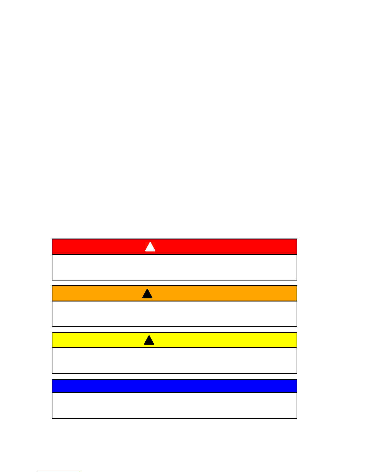
This manual as well as safety labels posted on the outboard use
the following safety alerts to draw your attention to special safety
instructions that should be followed.
!
DANGER
Indicates a hazardous situation which, if not avoided, will result
in death or serious injury.
!
WARNING
Indicates a hazardous situation which, if not avoided, could result
in death or serious injury.
!
CAUTION
Indicates a hazardous situation which, if not avoided, could result
in minor or moderate injury.
NOTICE
Indicates a situation which, if not avoided, could result in engine
or major component failure.
Page 25
GENERAL INFORMATION
17
Boat Horsepower Capacity
!
WARNING
Exceeding the boat's maximum horsepower rating can cause
serious injury or death. Overpowering the boat can affect boat
control and flotation characteristics or break the transom. Do not
install an engine that exceeds the boat's maximum power rating.
Do not overpower or overload your boat. Most boats will carry a
required capacity plate indicating the maximum acceptable power
and load as determined by the manufacturer following certain
federal guidelines. If in doubt, contact your dealer or the boat
manufacturer.
U.S. COAST GUARD CAP ACITY
MAXIMUM HORSEPOWER XXX
MAXIMUM PERSON
CAPACITY (POUNDS) XXX
MAXIMUM WEIGHT
CAPACITY XXX
26777
High‑Speed and High‑Performance Boat Operation
If your outboard is to be used on a high speed or high performance
boat with which you are unfamiliar, we recommend that you never
operate it at its high speed capability without first requesting an
initial orientation and familiarization demonstration ride with your
dealer or an operator experienced with your boat/outboard
combination. For additional information, obtain a copy of our
Hi‑Performance Boat Operation booklet from your dealer,
distributor, or Mercury Marine.
Outboard Remote Control Models
The remote control connected to your outboard must be equipped
with a start in neutral only protection device. This prevents the
engine from starting when the shift is actuated in any position other
than neutral.
Page 26
GENERAL INFORMATION
18
!
WARNING
Starting the engine with the drive in gear can cause serious injury
or death. Never operate a boat that does not have a
neutral‑safety‑protection device.
26779
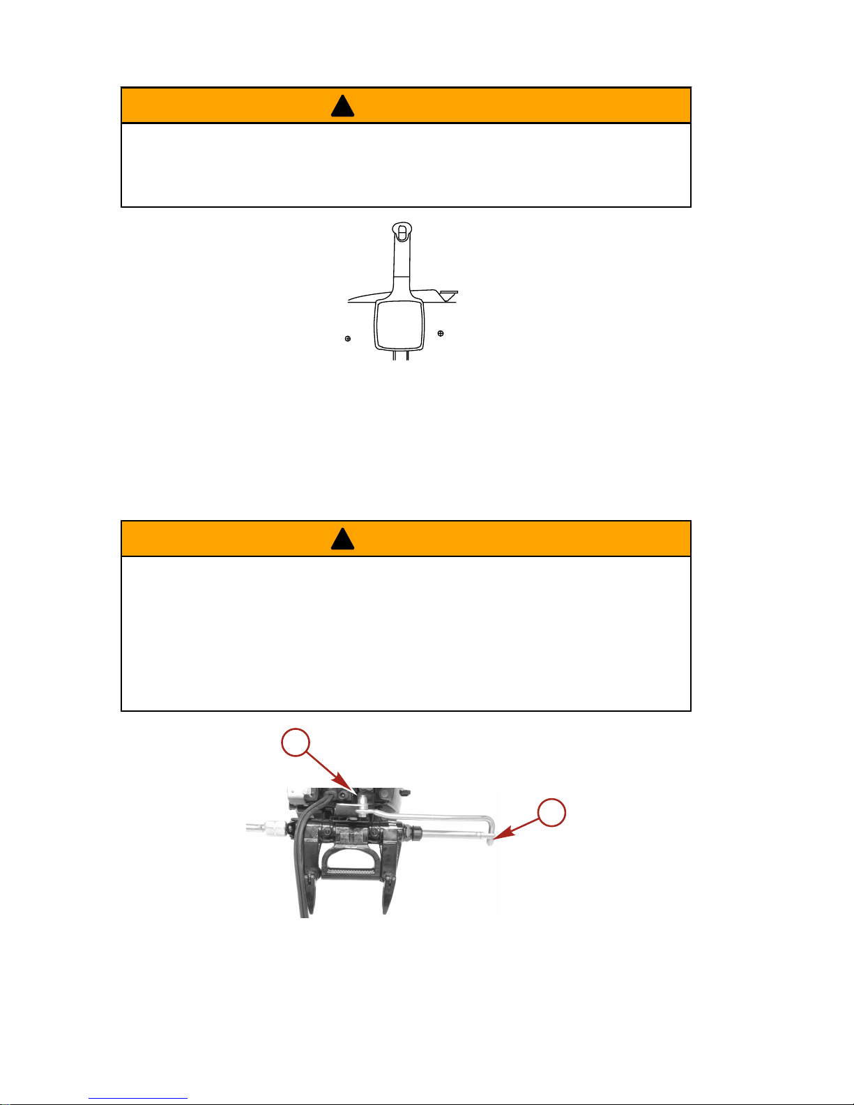
Remote Steering Notice
The steering link rod that connects the steering cable to the engine
must be fastened utilizing self‑locking nuts. These self‑locking nuts
must never be replaced with common nuts (non‑locking) as they
will work loose and vibrate off, freeing the link rod to disengage.
!
WARNING
Improper fasteners or improper installation procedures can result
in loosening or disengagement of the steering link rod. This can
cause a sudden, unexpected loss of boat control, resulting in
serious injury or death due to occupants being thrown within or
out of the boat. Always use required components and follow
instructions and torque procedures.
a
10366
a
a - Self‑locking nuts
Page 27
GENERAL INFORMATION
19
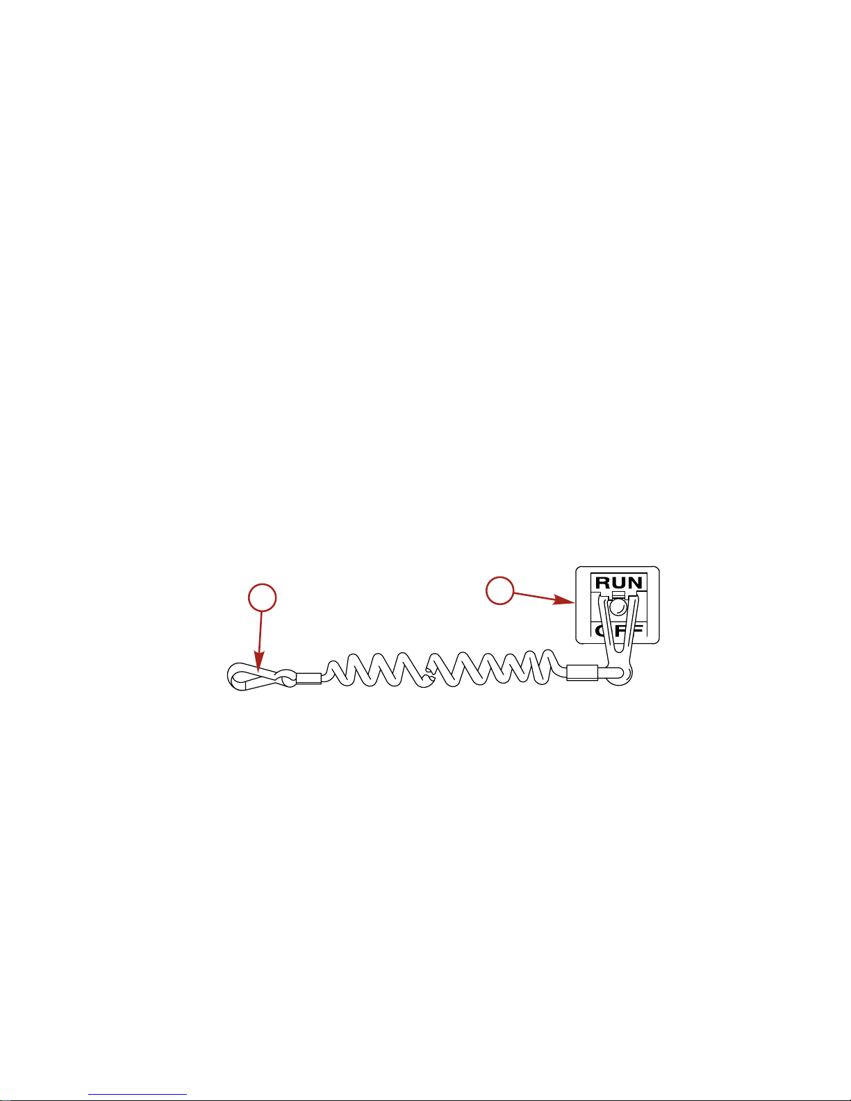
Lanyard Stop Switch
The purpose of a lanyard stop switch is to turn off the engine when
the operator moves far enough away from the operator's position
(as in accidental ejection from the operator's position) to activate
the switch. Tiller handle outboards and some remote control units
are equipped with a lanyard stop switch. A lanyard stop switch can
be installed as an accessory ‑ generally on the dashboard or side
adjacent to the operator's position.
The lanyard is a cord usually 122 ‑ 152 cm (4 ‑ 5 feet) in length
when stretched out, with an element on one end made to be
inserted into the switch and a snap on the other end for attaching
to the operator. The lanyard is coiled to make its at‑rest condition
as short as possible to minimize the likelihood of lanyard
entanglement with nearby objects. Its stretched‑out length is made
to minimize the likelihood of accidental activation should the
operator choose to move around in an area close to the normal
operator's position. If it is desired to have a shorter lanyard, wrap
the lanyard around the operator's wrist or leg, or tie a knot in the
lanyard.
21629
a
b
a - Lanyard cord b - Lanyard stop switch
Read the following Safety Information before proceeding.
Page 28
GENERAL INFORMATION
20
Important Safety Information: The purpose of a lanyard stop switch
is to stop the engine when the operator moves far enough away
from the operator's position to activate the switch. This would occur
if the operator accidentally falls overboard or moves within the boat
a sufficient distance from the operator's position. Falling overboard
and accidental ejections are more likely to occur in certain types
of boats such as low sided inflatables, bass boats, high
performance boats, and light, sensitive handling fishing boats
operated by a hand tiller. Falling overboard and accidental
ejections are also likely to occur as a result of poor operating
practices such as sitting on the back of the seat or gunwale at
planing speeds, standing at planing speeds, sitting on elevated
fishing boat decks, operating at planing speeds in shallow or
obstacle infested waters, releasing your grip on a steering wheel
or tiller handle that is pulling in one direction, drinking alcohol or
consuming drugs, or daring high speed boat maneuvers.
While activation of the lanyard stop switch will stop the engine
immediately, a boat will continue to coast for some distance
depending upon the velocity and degree of any turn at shut down.
However, the boat will not complete a full circle. While the boat is
coasting, it can cause injury to anyone in the boat's path as
seriously as the boat would when under power.
We strongly recommend that other occupants be instructed on
proper starting and operating procedures should they be required
to operate the engine in an emergency (e.g. if the operator is
accidentally ejected).
!
WARNING
If the operator falls out of the boat, stop the engine immediately
to reduce the possibility of serious injury or death from being
struck by the boat. Always properly connect the operator to the
stop switch using a lanyard.
!
WARNING
Avoid serious injury or death from deceleration forces resulting
from accidental or unintended stop switch activation. The boat
operator should never leave the operator's station without first
disconnecting the stop switch lanyard from the operator.
Page 29
GENERAL INFORMATION
21
Accidental or unintended activation of the switch during normal
operation is also a possibility. This could cause any, or all, of the
following potentially hazardous situations:
• Occupants could be thrown forward due to unexpected loss
of forward motion ‑ a particular concern for passengers in the
front of the boat who could be ejected over the bow and
possibly struck by the gearcase or propeller.
• Loss of power and directional control in heavy seas, strong
current or high winds.
• Loss of control when docking.
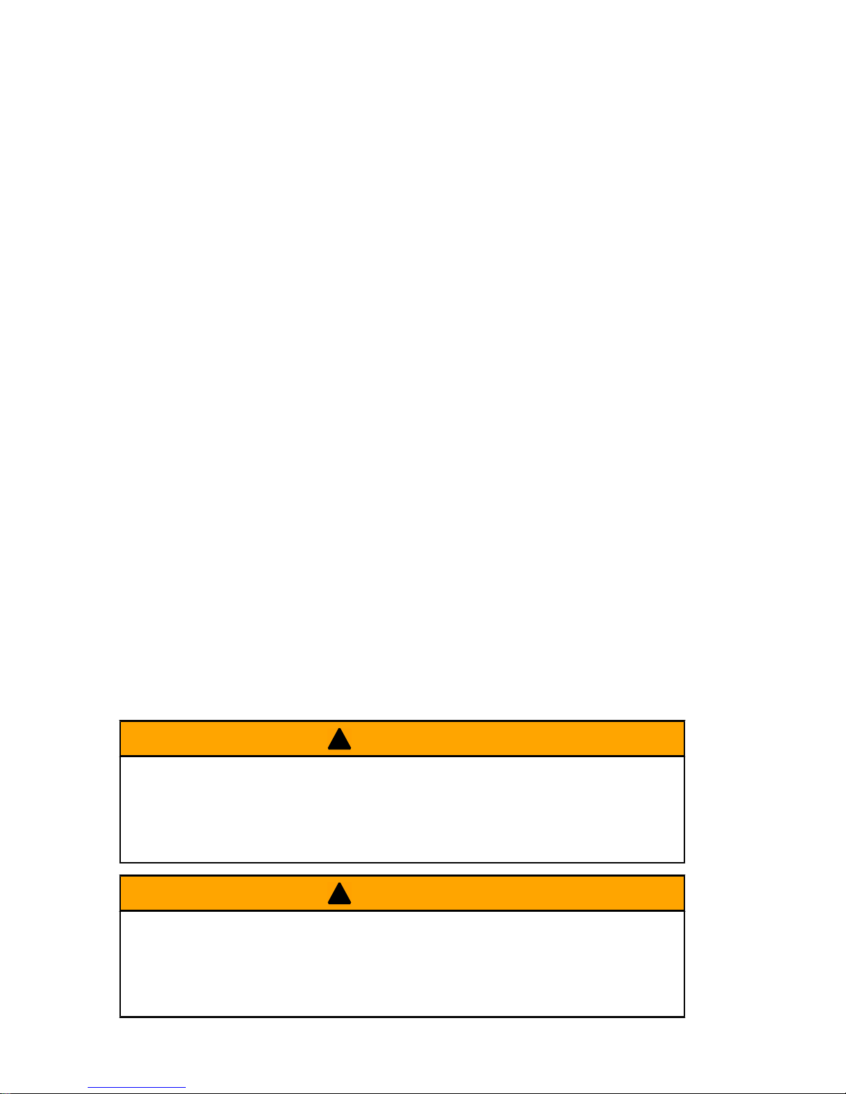
Protecting People In The Water
WHILE YOU ARE CRUISING
It is very difficult for a person standing or floating in the water to
take quick action to avoid a boat heading in his/her direction, even
at slow speed.
21604
Always slow down and exercise extreme caution any time you are
boating in an area where there might be people in the water.
Whenever a boat is moving (coasting) and the outboard gear shift
is in neutral position, there is sufficient force by the water on the
propeller to cause the propeller to rotate. This neutral propeller
rotation can cause serious injury.
WHILE BOAT IS STATIONARY
!
WARNING
A spinning propeller, a moving boat, or any solid device attached
to the boat can cause serious injury or death to swimmers. Stop
the engine immediately whenever anyone in the water is near
your boat.
Page 30
GENERAL INFORMATION
22
Shift outboard into neutral and shut off the engine before allowing
people to swim or be in the water near your boat.
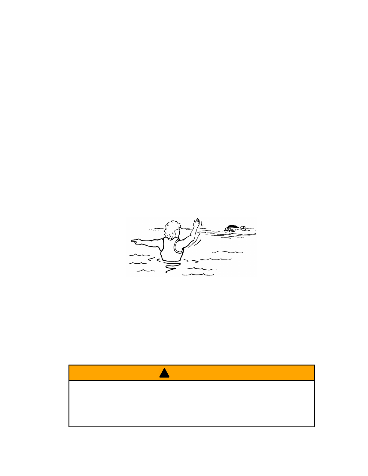
Passenger Safety Message ‑ Pontoon Boats And
Deck Boats
Whenever the boat is in motion, observe the location of all
passengers. Do not allow any passengers to stand or use seats
other than those designated for traveling faster than idle speed. A
sudden reduction in boat speed, such as plunging into a large wave
or wake, a sudden throttle reduction, or a sharp change of boat
direction, could throw them over the front of the boat. Falling over
the front of the boat between the two pontoons will position them
to be run over by the outboard.
BOATS HAVING AN OPEN FRONT DECK
No one should ever be on the deck in front of the fence while the
boat is in motion. Keep all passengers behind the front fence or
enclosure.
Persons on the front deck could easily be thrown overboard or
persons dangling their feet over the front edge could get their legs
caught by a wave and pulled into the water.
26782
!
WARNING
Sitting or standing in an area of the boat not designed for
passengers at speeds above idle can cause serious injury or
death. Stay back from the front end of deck boats or raised
platforms and remain seated while the boat is in motion.
Page 31
GENERAL INFORMATION
23
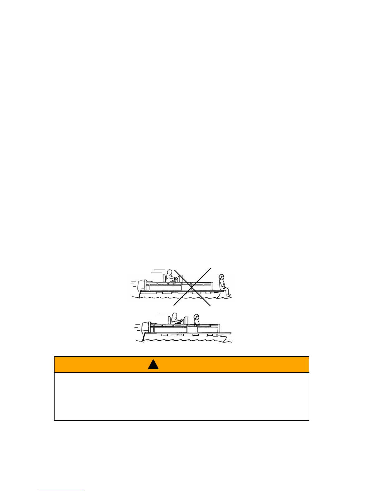
BOATS WITH FRONT MOUNTED, RAISED PEDESTAL
FISHING SEATS
Elevated fishing seats are not intended for use when the boat is
traveling faster than idle or trolling speed. Sit only in seats
designated for traveling at faster speeds.
Any unexpected, sudden reduction in boat speed could result in
the elevated passenger falling over the front of the boat.
26783
Wave And Wake Jumping
Operating recreational boats over waves and wake is a natural part
of boating. However, when this activity is done with sufficient speed
to force the boat hull partially or completely out of the water, certain
hazards arise, particularly when the boat re‑enters the water.
26784
The primary concern is the boat changing direction while in the
midst of the jump. In such case the landing may cause the boat to
veer violently in a new direction. Such a sharp change in direction
can cause occupants to be thrown out of their seats, or out of the
boat.
Page 32

GENERAL INFORMATION
24
!
WARNING
Wave or wake jumping can cause serious injury or death from
occupants being thrown within or out of the boat. Avoid wave or
wake jumping whenever possible.
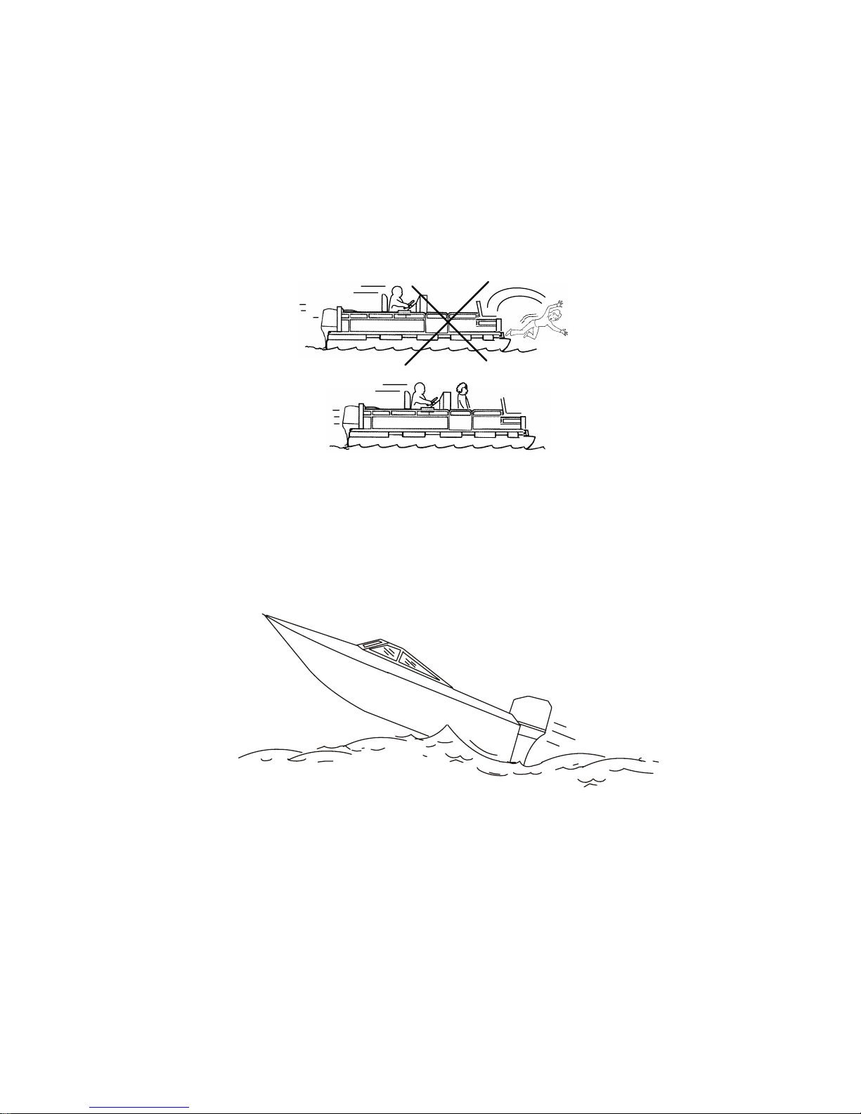
There is another less common hazardous result from allowing your
boat to launch off a wave or wake. If the bow of your boat pitches
down far enough while airborne, upon water contact it may
penetrate under the water surface and submarine for an instant.
This will bring the boat to a nearly instantaneous stop and can send
the occupants flying forward. The boat may also steer sharply to
one side.
Impact with Underwater Hazards
Reduce speed and proceed with caution whenever you drive a
boat in shallow water areas, or in areas where you suspect
underwater obstacles may exist which could be struck by the
outboard or the boat bottom. The most important thing you can do
to help reduce injury or impact damage from striking a floating or
underwater object is to control the boat speed. Under these
conditions, boat speed should be kept to a minimum planing speed
of 24 to 40 km/h (15 to 25 MPH).
26785
Striking a floating or underwater object could result in an infinite
number of situations. Some of these situations could result in the
following:
• Part of the outboard or the entire outboard could break loose
and fly into the boat.
Page 33

GENERAL INFORMATION
25
• The boat could move suddenly in a new direction. Such a
sharp change in direction can cause occupants to be thrown
out of their seats or out of the boat.
• A rapid reduction in speed. This will cause occupants to be
thrown forward, or even out of the boat.
• Impact damage to the outboard and/or boat.
Keep in mind, the most important thing you can do to help reduce
injury or impact damage during an impact is control the boat speed.
Boat speed should be kept to a minimum planing speed when
driving in waters known to have underwater obstacles.
After striking a submerged object, stop the engine as soon as
possible and inspect it for any broken or loose parts. If damage is
present or suspected, the outboard should be taken to an
authorized dealer for a thorough inspection and necessary repair.
The boat should also be checked for any hull fractures, transom
fractures, or water leaks.
Operating a damaged outboard could cause additional damage to
other parts of the outboard, or could affect control of the boat. If
continued running is necessary, do so at greatly reduced speeds.
!
WARNING
Operating a boat or engine with impact damage can result in
product damage, serious injury, or death. If the vessel
experiences any form of impact, have an authorized Mercury
Marine dealer inspect and repair the vessel or power package.
SAFETY INSTRUCTIONS FOR HAND TILLED OUTBOARDS
No person or cargo should occupy the area directly in front of the
outboard while the boat is in motion. If an underwater obstacle is
struck, the outboard will tilt up and could seriously injure anyone
occupying this area.
Page 34
GENERAL INFORMATION
26
Models With Clamp Screws:
Some outboards come with transom bracket clamp screws. The
use of clamp bracket screws alone, is insufficient to properly and
safely secure the outboard to the transom. Proper installation of
the outboard includes bolting the engine to the boat through the
transom. Refer to Installation - Installing Outboard for more
complete installation information.
!
WARNING
Failure to correctly fasten the outboard could result in the
outboard propelling off the boat transom resulting in property
damage, serious injury, or death. Before operation, the outboard
must be correctly installed with the required mounting hardware.
Do not accelerate above idle speed in water that may contain
underwater obstacles if the outboard is not attached to the
transom correctly.
If an obstacle is struck at planing speed and the outboard is not
securely fastened to the transom, it is possible the outboard could
lift off the transom and land in the boat.
Exhaust Emissions
BE ALERT TO CARBON MONOXIDE POISONING
Carbon monoxide is present in the exhaust fumes of all internal
combustion engines. This includes the outboards, sterndrives and
inboard engines that propel boats, as well as the generators that
power various boat accessories. Carbon monoxide is a deadly gas
that is odorless, colorless and tasteless.
Early symptoms of carbon monoxide poisoning which should not
be confused with seasickness or intoxication, include headache,
dizziness, drowsiness, and nausea.
!
WARNING
Carbon monoxide poisoning can lead to unconsciousness, brain
damage, or death. Keep the boat well ventilated while at rest or
underway and avoid prolonged exposure to carbon monoxide.
Page 35
GENERAL INFORMATION
27
GOOD VENTILATION
Ventilate passenger area, open side curtains, or forward hatches
to remove fumes.
21622
Example of desired air flow through the boat
POOR VENTILATION
Under certain running and/or wind conditions, permanently
enclosed or canvas enclosed cabins or cockpits with insufficient
ventilation may draw in carbon monoxide. Install one or more
carbon monoxide detectors in your boat.
Although the occurrence is rare, on a very calm day, swimmers
and passengers in an enclosed area of a stationary boat that
contains or is near a running engine may be exposed to a
hazardous level of carbon monoxide.
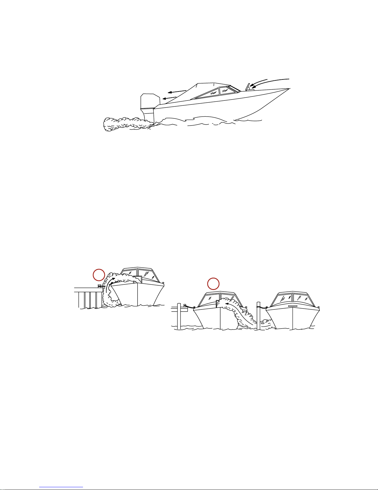
WHILE BOAT IS STATIONARY
21626
a
b
a - Running the engine when the boat is moored in a confined
space
b - Mooring close to another boat that has its engine running
Page 36

GENERAL INFORMATION
28
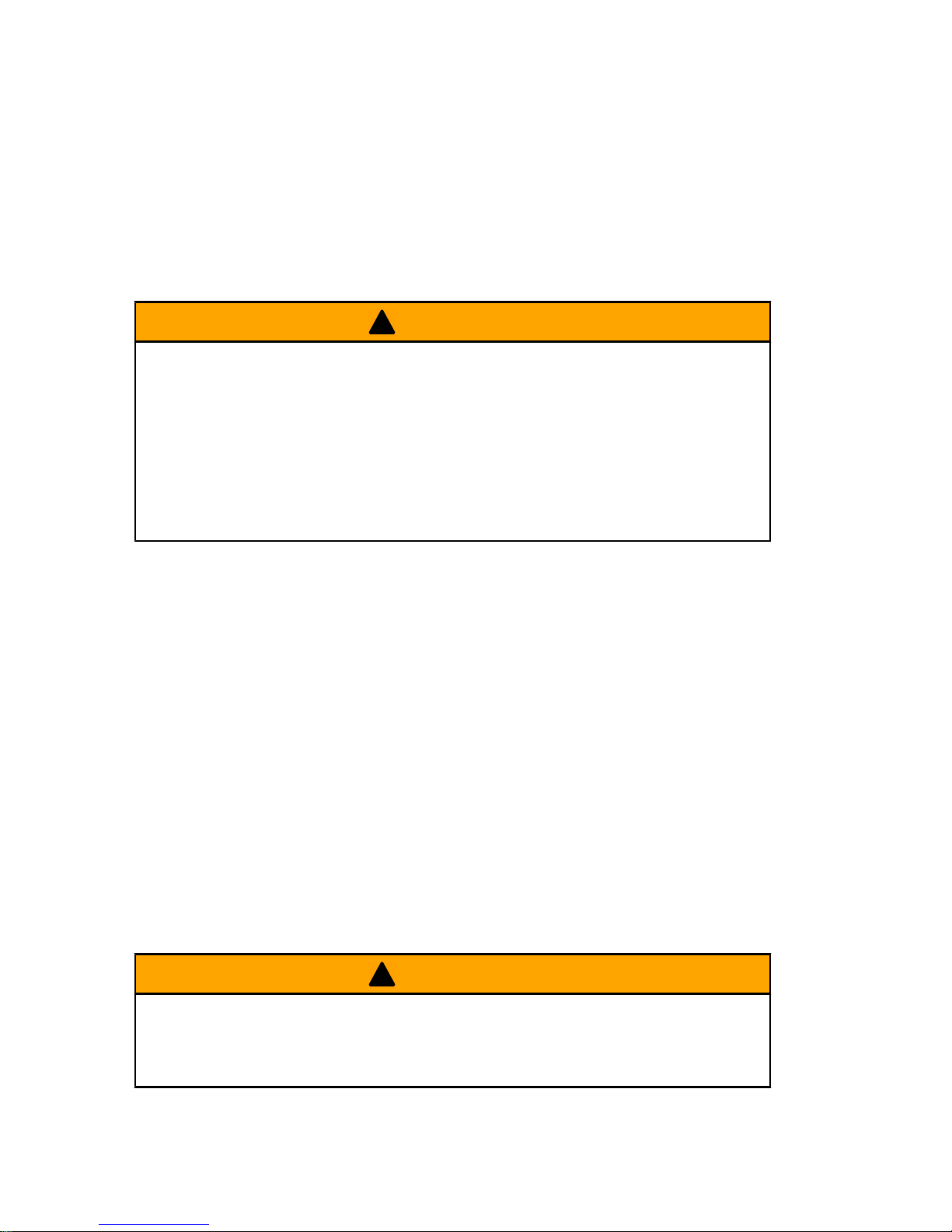
WHILE BOAT IS MOVING
a
b
21628
a - Running the boat with the trim angle of the bow too high
b - Running the boat with no forward hatches open
Selecting Accessories For Your Outboard
Genuine Mercury Precision or Quicksilver Accessories have been
specifically designed and tested for your outboard. These
accessories are available from Mercury Marine dealers.
IMPORTANT: Check with your dealer before installing
accessories. The misuse of approved accessories or the use of
non‑approved accessories can damage the product.
Some accessories not manufactured or sold by Mercury Marine
are not designed to be safely used with your outboard or outboard
operating system. Acquire and read the installation, operation, and
maintenance manuals for all your selected accessories.
Safe Boating Suggestions
In order to safely enjoy the waterways, familiarize yourself with
local and other governmental boating regulations and restrictions,
and consider the following suggestions.
Use flotation devices. Have an approved personal flotation device
of suitable size for each person aboard (it is the law) and have it
readily accessible.
Do not overload your boat. Most boats are rated and certified for
maximum load (weight) capacities (refer to your boat capacity
plate). If in doubt, contact your dealer or the boats manufacturer.
Perform safety checks and required maintenance. Follow a regular
schedule and ensure that all repairs are properly made.
Page 37

GENERAL INFORMATION
29
Know and obey all nautical rules and laws of the waterways. Boat
operators should complete a boating safety course. Courses are
offered in the U.S.A. by 1) The U.S. Coast Guard Auxiliary, 2) The
Power Squadron, 3) The Red Cross and 4) your state boating law
enforcement agency. Inquiries may be made to the Boating
Hotline, 1‑800‑368‑5647 or the Boat U.S. Foundation information
number 1‑800‑336‑BOAT.
Make sure everyone in the boat is properly seated. Do not allow
anyone to sit or ride on any part of the boat that was not intended
for such use. This includes the back of seats, gunwales, transom,
bow, decks, raised fishing seats, any rotating fishing seat; or
anywhere that an unexpected acceleration, sudden stopping,
unexpected loss of boat control, or sudden boat movement could
cause a person to be thrown overboard or into the boat.
Never be under the influence of alcohol or drugs while boating (it
is the law). Alcohol or drug use impairs your judgment and greatly
reduces your ability to react quickly.
Prepare other boat operators. Instruct at least one other person on
board in the basics of starting and operating the outboard, and boat
handling, in case the driver becomes disabled or falls overboard.
Passenger boarding. Stop the engine whenever passengers are
boarding, unloading, or are near the back (stern) of the boat. Just
shifting the outboard into neutral is not sufficient.
Be alert. The operator of the boat is responsible by law to maintain
a proper lookout by sight and hearing. The operator must have an
unobstructed view particularly to the front. No passengers, load,
or fishing seats should block the operators view when operating
the boat above idle speed.
Never drive your boat directly behind a water skier in case the skier
falls. As an example, your boat traveling at 40 km/h (25 MPH) will
overtake a fallen skier 61 m (200 ft.) in front of you in 5 seconds.
Watch fallen skiers. When using your boat for water skiing or
similar activities, always keep a fallen or down skier on the
operator's side of the boat while returning to assist the skier. The
operator should always have the down skier in sight and never
back up to the skier or anyone in the water.
Page 38

GENERAL INFORMATION
30
Report accidents. Boat operators are required by law to file a
Boating Accident Report with their state boating law enforcement
agency when their boat is involved in certain boating accidents. A
boating accident must be reported if 1) there is loss of life or
probable loss of life, 2) there is personal injury requiring medical
treatment beyond first aid, 3) there is damage to boats or other
property where the damage value exceeds $500.00 or 4) there is
complete loss of the boat. Seek further assistance from local law
enforcement.
Recording Serial Number
It is important to record this number for future reference. The serial
number is located on the outboard as shown.
XXXX
XX
XXXXXXXX
XXXX
a
b
c
d
e
28498
a - Serial number
b - Model year
c - Model designation
d - Year manufactured
e - Certified Europe Insignia
(as applicable)
8/9.9 4‑Stroke Specifications ‑ International
Models 8.0 9.9 9.9 Bigfoot
Horsepower 8.0 9.9
Kilowatts 5.9 7.2
Weight
MH 38.3 kg (84 lb.) N/A
MLH 39.2 kg (86 lb.) 43.5 kg (95.9 lb.)
MXLH N/A 45 kg (99.2 lb.)
EH 41.1 kg (91 lb.) N/A
ELH 42.3 kg (93 lb.) 46.6 kg (102.7 lb.)
Page 39

GENERAL INFORMATION
31
Models 8.0 9.9 9.9 Bigfoot
EXLH N/A 48.1 kg (106 lb.)
ELHPT N/A 50.4 kg (111.1 lb.)
EXLHPT N/A 51.9 kg (114.4 lb.)
MRC 36.5 kg (80 lb.) N/A
ELRC 40.7 kg (90 lb.) 45.1 kg (99.4 lb.)
EXLRC N/A 46.6 kg (102.7 lb.)
ELPT N/A 48.9 kg (107.8 lb.)
EXLRCPT N/A 50.4 kg (111.1 lb.)
Number of Cylinders 2
Full Throttle RPM Range 5000‑6000 RPM
Idle Speed in Forward
Gear
900 RPM
Piston Displacement 209.8 cc (12.8 cu. in.)
Cylinder Bore 55 mm (2.17 in.)
Piston Stroke 44 mm (1.73 in.)
Valve Clearance (Cold)
Intake Valve 0.13‑0.17 mm (0.0051‑0.0067 in.)
Exhaust Valve 0.18‑0.22 mm (0.0071‑0.0087 in.)
Recommended Spark
Plug
NGK DCPR6E
Spark Plug Gap 0.8‑0.9 mm (0.031‑ 0.035 in.)
Gear Ratio 2.08:1 2.42:1
Recommended
Gasoline
Refer to Fuel & Oil
Recommended Oil Refer to Fuel & Oil
Engine Oil Capacity 800 ml (27.0 fl. oz.)
Gearcase Lubricant
Capacity
320 ml (10.8 fl. oz.) 370 ml (12.5 fl. oz.)
Battery Rating (electric
start models)
465 Marine Cranking Amps (MCA) or 350 Cold
Cranking Amps (CCA)
Sound at Drivers Ear
(ICOMIA 39‑94)
4‑Stroke 79.6
Page 40
GENERAL INFORMATION
32
Component Identification ‑ Standard Models
STARBOARD SIDE VIEW
a
c
d
k
e
f
g
h
i
j
28508
b
a - Cowl latch
b - Throttle only button
c - Throttle friction
adjustment knob
d - Water pump indicator
hole
e - Oil drain plug
f - Transom angle preset
knob
g - Engine flush plug
h - Gear lubricant level plug
i - Water inlet
j - Gear lubricant fill/drain
plug
k - Trim tab
Page 41

GENERAL INFORMATION
33
FRONT VIEW
a
b
c
d
e
f
g
28527
a - Choke/fast idle knob
b - Fuel primer
c - Oil pressure light
d - Fuel line connector
e - Start switch (electric tiller
handle)
f - Lanyard safety switch
g - Trim/tilt position indicator
PORT VIEW
a
b
c
d
28529
a - Tiller lock release lever
b - Start switch (electric
tiller handle model)
c - Steering friction
adjustment lever (tiller
model only)
d - Tilt lock knob
Page 42

GENERAL INFORMATION
34
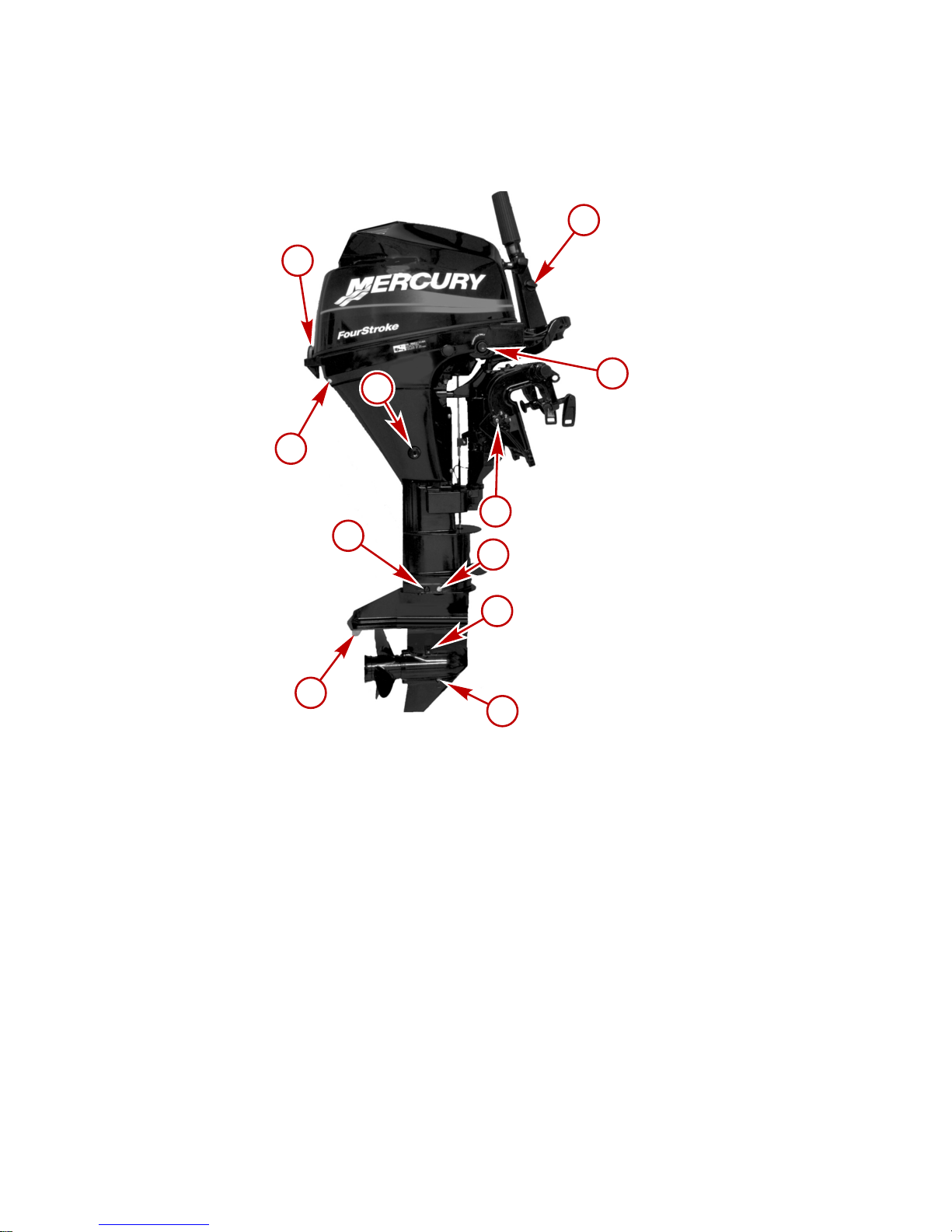
Component Identification ‑ Bigfoot Models
a
b
c
d
e
f
g
h
i
4538
j
l
m
n
k
o
a - Transom bracket
b - Tilt support lever
c - Gear lubricant level plug
d - Water inlet
e - Gear lubricant fill/drain
plug
f - Anti‑ventilation plate
g - Engine flush plug
h - Water pump indicator
hole
i - Cowl latch
j - Oil drain screw
k - Power tilt
l - Kicker strap
m -Throttle only button
n - Throttle grip friction knob
o - Power tilt button
Page 43

TRANSPORTING
35
Carrying, Storing and Transporting Your Outboard
When Removed From Boat
IMPORTANT: Ensure the proper procedures are followed for
transportation and storage of the outboard to avoid the possibility
of oil leaks.
1. With the outboard still in the water, disconnect the remote fuel
line and run engine until it stops. This will drain fuel from the
carburetor. Install the protector cap over the fuel connector.
a
28530
a - Protector cap
2. Remove outboard and hold it upright until the water is drained
out. Keep the outboard in an upright position when carrying.
27010
Page 44

TRANSPORTING
36
3. Carry, transport or store the outboard only in one of the four
positions shown. These positions will prevent oil from draining
out of the crankcase.
abc
d
10375
a - Upright position
b - Tiller handle down
c - Front side up
d - Front side down
4. Never carry, store or transport the outboard in the position
shown. Engine damage could result from oil draining out of
the crankcase.
10378
Transporting Portable Fuel Tanks
!
WARNING
Avoid serious injury or death from a gasoline fire or explosion.
Follow the transporting instructions supplied with the portable
fuel tank. Transport the fuel tank in a well ventilated area away
from open flame or sparks.
Page 45

TRANSPORTING
37
MANUAL VENTING TYPE FUEL TANK
1. Close fuel tank air vent when transporting tank. This will
prevent escape of fuel or vapors from tank.
26793
AUTO-VENTING TYPE FUEL TANK
1. Disconnect the remote fuel line from tank. This will close the
air vent and prevent escape of fuel or vapors from tank.
2. Install tether cap over the fuel line connector stem. This will
protect the connector stem from being accidently pushed‑in,
thus, allowing fuel or vapor to escape.
F
a
b
26794
a - Connector stem b - Tether cap
Trailering Boat/Outboard ‑ Models with Power Tilt
Trailer your boat with the outboard tilted down in a vertical
operating position.
Page 46

TRANSPORTING
38
If additional ground clearance is required, the outboard should be
tilted up using an accessory outboard support device. Refer to your
local dealer for recommendations. Additional clearance may be
required for railroad crossings, driveways and trailer bouncing.
26792
IMPORTANT: Do not rely on the power tilt system or tilt support
lever to maintain proper ground clearance for trailering. The
outboard tilt support lever is not intended to support the outboard
for trailering.
Shift the outboard to forward gear. This prevents the propeller from
spinning freely.
Trailering Boat/Outboard ‑ Models without Power
Tilt
Trailer your boat with the outboard tilted down in a vertical
operating position.
If additional ground clearance is required, the outboard should be
tilted up using the shallow water drive/trailering bracket. Additional
clearance may be required for railroad crossings, driveways, and
trailer bouncing.
IMPORTANT: The tilt lock lever should be used to lock the
outboard down when trailering. This will prevent the outboard from
bouncing and causing possible damage to the outboard.
Shift the outboard to forward gear. This prevents the propeller from
spinning freely.
Page 47

FUEL AND OIL
39
Fuel Recommendations
IMPORTANT: Use of improper gasoline can damage your
engine. Engine damage resulting from the use of improper
gasoline is considered misuse of the engine, and damage
caused thereby will not be covered under the limited warranty.
FUEL RATINGS
Mercury Marine engines will operate satisfactorily when using a
major brand of unleaded gasoline meeting the following
specifications:
USA and Canada ‑ having a posted pump Octane Rating of 87 (R
+M)/2 minimum. Premium gasoline [92 (R+M)/2 Octane] is also
acceptable. Do NOT use leaded gasoline.
Outside USA and Canada ‑ having a posted pump Octane Rating
of 90 RON minimum. Premium gasoline (98 RON) is also
acceptable. If unleaded gasoline is not available, use a major
brand of leaded gasoline.
USING REFORMULATED (OXYGENATED) GASOLINES
(USA ONLY)
This type of gasoline is required in certain areas of the USA. The
2 types of oxygenates used in these fuels are Alcohol (Ethanol) or
Ether (MTBE or ETBE). If Ethanol is the oxygenate that is used in
the gasoline in your area, refer to Gasolines Containing Alcohol.
These Reformulated Gasolines are acceptable for use in your
Mercury Marine engine.
GASOLINES CONTAINING ALCOHOL
If the gasoline in your area contains either methanol (methyl
alcohol) or ethanol (ethyl alcohol), you should be aware of certain
adverse effects that can occur. These adverse effects are more
severe with methanol. Increasing the percentage of alcohol in the
fuel can also worsen these adverse effects.
Some of these adverse effects are caused because the alcohol in
the gasoline can absorb moisture from the air, resulting in a
separation of the water/alcohol from the gasoline in the fuel tank.
Page 48
FUEL AND OIL
40
The fuel system components on your Mercury Marine engine will
withstand up to 10% alcohol content in the gasoline. We do not
know what percentage your boat's fuel system will withstand.
Contact your boat manufacturer for specific recommendations on
the boat's fuel system components (fuel tanks, fuel lines, and
fittings). Be aware that gasolines containing alcohol may cause
increased:
• Corrosion of metal parts
• Deterioration of rubber or plastic parts
• Fuel permeation through rubber fuel lines
• Starting and operating difficulties
!
WARNING
Fuel leakage is a fire or explosion hazard, which can cause
serious injury or death. Periodically inspect all fuel system
components for leaks, softening, hardening, swelling, or
corrosion, particularly after storage. Any sign of leakage or
deterioration requires replacement before further engine
operation.
Because of possible adverse effects of alcohol in gasoline, it is
recommended that only alcohol‑free gasoline be used where
possible. If only fuel containing alcohol is available, or if the
presence of alcohol is unknown, increased inspection frequency
for leaks and abnormalities is required.
IMPORTANT: When operating a Mercury Marine engine on
gasoline containing alcohol, storage of gasoline in the fuel tank for
long periods should be avoided. Long periods of storage, common
to boats, create unique problems. In cars, alcohol‑blend fuels
normally are consumed before they can absorb enough moisture
to cause trouble, but boats often sit idle long enough for phase
separation to take place. In addition, internal corrosion may take
place during storage if alcohol has washed protective oil films from
internal components.
Page 49

FUEL AND OIL
41
Filling Fuel Tank
!
WARNING
Avoid serious injury or death from a gasoline fire or explosion.
Use caution when filling fuel tanks. Always stop the engine and
do not smoke or allow open flames or sparks in the area while
filling fuel tanks.
Fill fuel tanks outdoors away from heat, sparks, and open flames.
Remove portable fuel tanks from boat to refill them.
Always stop engine before refilling tanks.
Do not completely fill the fuel tanks. Leave approximately 10% of
the tank volume unfilled. Fuel will expand in volume as its
temperature rises and can leak under pressure if the tank is
completely filled.
PORTABLE FUEL TANK PLACEMENT IN THE BOAT
Place the fuel tank in the boat so the vent is higher than the fuel
level under normal boat operating conditions.
Page 50

FUEL AND OIL
42
Engine Oil Recommendations
We recommend the use of Mercury or Quicksilver SAE 10W‑30
multi‑viscosity 4‑Stroke Outboard Oil for general, all‑temperature
use. If SAE 25W‑40 multi‑viscosity oil is preferred, use Mercury
MerCruiser 4‑cycle engine oil or Quicksilver sterndrive & inboard
4‑cycle engine oil. Never use 4‑cycle engine oil that is not certified
to meet or exceed any one or combination of the following
American Petroleum Institute (API) Service Classification SH, SG,
SF, CF‑4, CE, CD, CDII. Severe engine damage may result from
use of an inferior oil.
+20
+40
+60
+80
F° C°
0
+100
–7
+4
+16
+27
–18
+38
a
b
26795
Recommended SAE Viscosity for Engine Oil
a - SAE 25W‑40 viscosity oil may be used at temperatures
above 4 °C (40 °F)
b - SAE 10W‑30 viscosity oil is recommended for use in all
temperatures.
Checking Engine Oil
IMPORTANT: Do not overfill. Be sure that the outboard is upright
(not tilted) when checking oil.
Page 51

FUEL AND OIL
43
1. Turn the engine off. Have the outboard in a level operating
position. Remove the top cowl.
2. Remove dipstick. Wipe dipstick with a clean rag or towel and
push it back in all the way.
3. Pull the dipstick out again and observe the oil level. If oil level
is low, remove oil filler cap and fill to (but not over) the full mark
with the recommended oil.
IMPORTANT: Inspect oil for signs of contamination. Oil
contaminated with water will have a milky color to it; oil
contaminated with fuel will have a strong fuel smell. If
contaminated oil is noticed, have the engine checked by your
dealer.
4. Reinstall the oil filler cap and tighten securely.
4914
a
b
a - Dipstick b - Oil filler cap
Page 52
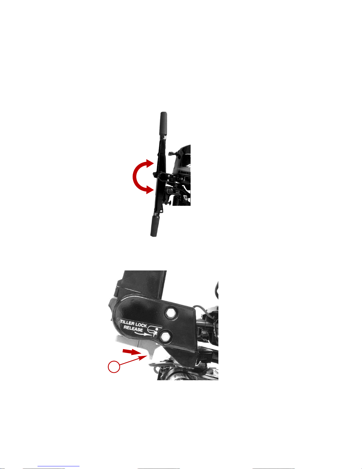
FEATURES AND CONTROLS
44
Tiller Handle Features
IMPORTANT: Avoid engine flooding ‑ Do not rotate the throttle grip
while engine is not running. Doing so will inject fuel into the engine
and cause a possible hard starting flooded condition.
• Tiller Handle ‑ Handle can be tilted 180° for convenient
handling during transportation and storage.
28535
• Tiller Lock Release Lever ‑ Push lever to move tiller handle
from one position to another.
a
3274
Page 53
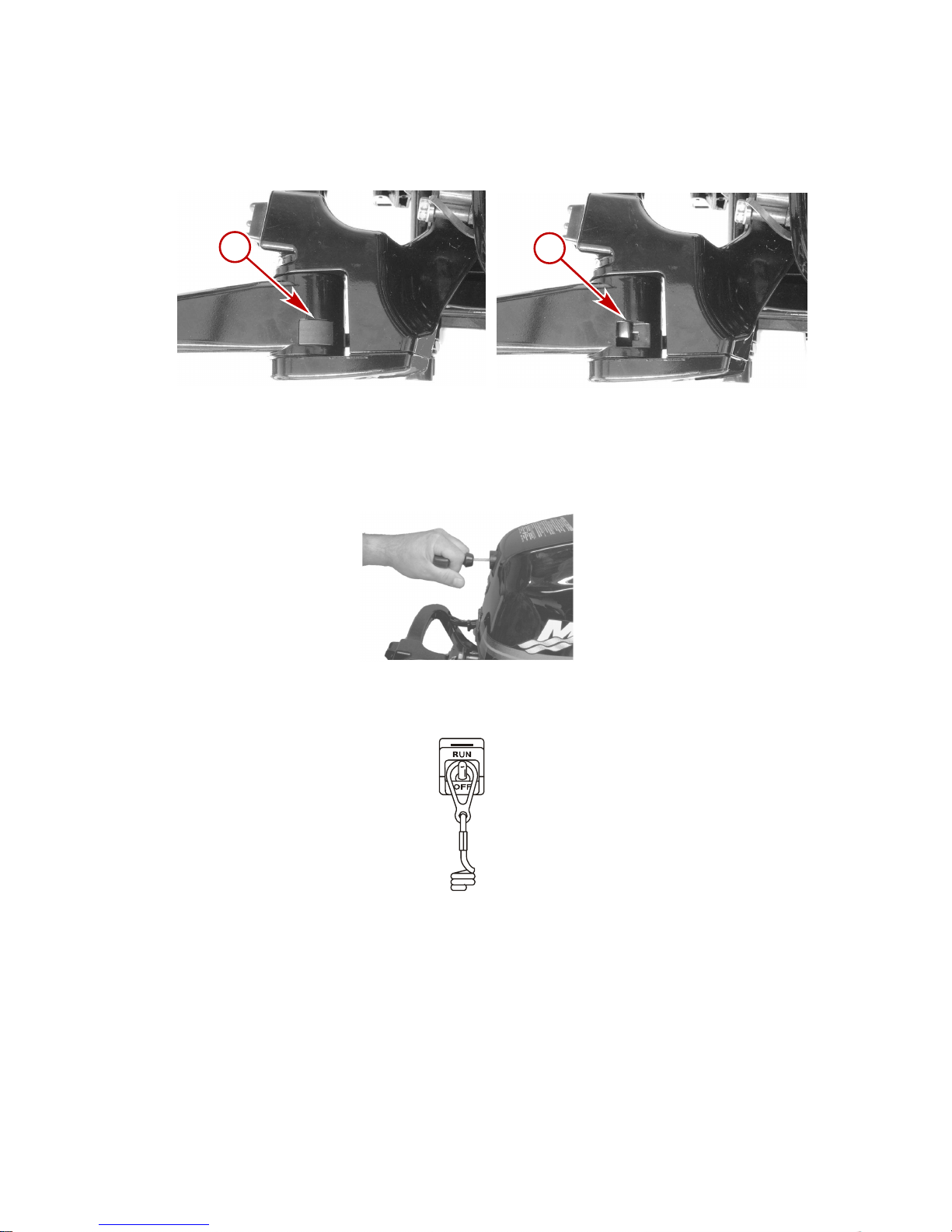
FEATURES AND CONTROLS
45
• Tiller Handle Lock Cap ‑ Remove the lock cap on top of tiller
handle to lock in up position. Push tiller lock release lever to
release the handle from the locked up position.
a
b
3273
a - Lock cap b - Locking mechanism
• Starter Rope ‑ Pulling the starter rope cranks the engine over
for starting.
28536
• Lanyard Stop Switch ‑ Refer to General Information ‑ Lanyard
Stop Switch.
19791
Page 54
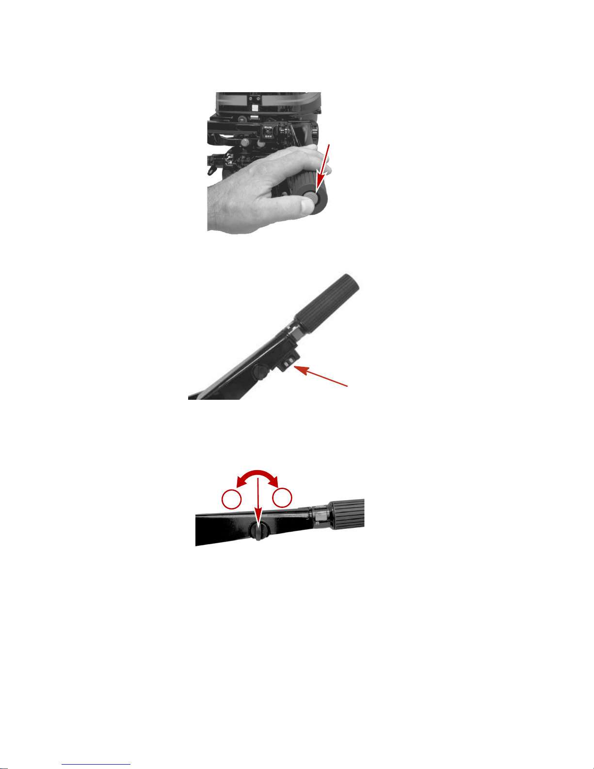
FEATURES AND CONTROLS
46
• Engine Stop Switch ‑ Push in to stop engine.
28537
• Power Tilt Switch ‑ Push to tilt engine up/down.
4639
• Throttle Grip Friction Knob ‑ Turn friction knob to set and
maintain the throttle at desired speed. Turn knob clockwise to
tighten friction or turn knob counterclockwise to loosen friction.
a
b
28542
a - Loosen friction (counterclockwise)
b - Tighten friction (clockwise)
Page 55

FEATURES AND CONTROLS
47
• Throttle Only Button ‑ Pressing the button in while the
outboard is in neutral disables the gear shift control of the tiller
handle.
28550
• Throttle Grip ‑ Controls engine speed and shifting.
a
b
28543
a - Reverse b - Forward
• Choke ‑ Pull out when starting a cold engine.
28544
• Fuel primer ‑ Press in when starting a cold engine. Refer to
Operation - Starting The Engine.
28548
Page 56

FEATURES AND CONTROLS
48
• Low oil pressure warning light ‑ Warns the operator the engine
has low oil pressure. When the low oil pressure light is on or
is blinking, the engine will run rough and will not exceed 3000
RPM.
28549
• Electric Start Button (Electric Start Models) ‑ Press button to
start engine.
28532
!
WARNING
Insufficient friction adjustment can cause serious injury or death
due to loss of boat control. When setting the friction adjustment,
maintain sufficient steering friction to prevent the outboard from
steering into a full turn if the tiller handle or steering wheel is
released.
Page 57

FEATURES AND CONTROLS
49
• Steering Friction Adjustment ‑ Adjust this lever to achieve the
desired steering friction (drag) on the tiller handle. Move lever
to the left to tighten, or move lever to the right to loosen.
28546
a - Tighten
b - Loosen
• Tilt Lock Knob ‑ Locks the engine in the full tilt position.
28564
• Trim Position Knob ‑ Pre‑sets the trim position.
28551
Page 58

FEATURES AND CONTROLS
50
• Kicker Strap (Power Tilt Models) ‑ Prevents the engine from
turning while tilted up.
4676
Page 59

FEATURES AND CONTROLS
51
Remote Control Features
Your boat may be equipped with one of the Mercury Precision or
Quicksilver remote controls shown. If not, consult your dealer for
a description of the functions and operations of the remote control.
f
a
c
d
e
b
h
c
a
g
d
e
b
i
f
g
i
c
a
f
26800
a - Control handle ‑ forward, neutral, reverse.
b - Neutral release lever
c - Trim/tilt switch (if equipped). ‑ Refer to Features &
Controls ‑ Power Trim and Tilt.
d - Lanyard stop switch ‑ Refer to General Information ‑
Lanyard Stop Switch.
e - Lanyard ‑ Refer to General Information ‑ Lanyard Stop
Switch.
f - Throttle friction adjustment ‑ Console controls require
cover removal for adjustment.
g - Ignition key switch ‑ "OFF," "ON," START."
h - Fast idle lever ‑ Refer to Operation ‑ Starting the
Engine.
i - Throttle only button ‑ Refer to Operation ‑ Starting the
Engine.
Page 60
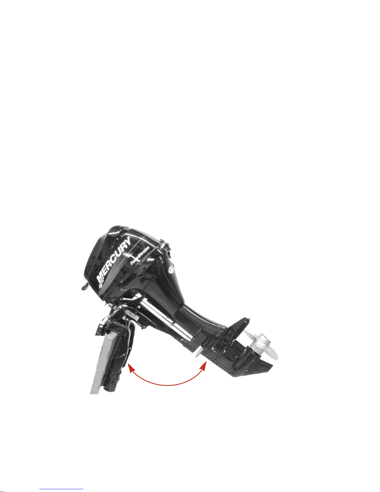
FEATURES AND CONTROLS
52
Warning System
The warning system on this engine does not have a warning horn.
Instead, there is an oil pressure light located on the front of the
engine. If oil pressure drops below 25 kPa (3.6 PSI) the oil pressure
light will illuminate, the Engine Guardian System will be activated,
and engine RPM will be limited to 3000.
The Engine Guardian System will also limit RPM of the engine in
the event of an over‑speed condition due to cavitation, no load on
propeller, and/or under propped.
Power Tilt (if equipped)
This outboard has a tilt control called power tilt. This enables the
operator to easily adjust the position of the outboard by pressing
the tilt switch. With the engine turned off, the outboard can be tilted
out of the water. At low idle speed, the outboard can also be tilted
up to permit shallow water operation.
4649
Page 61
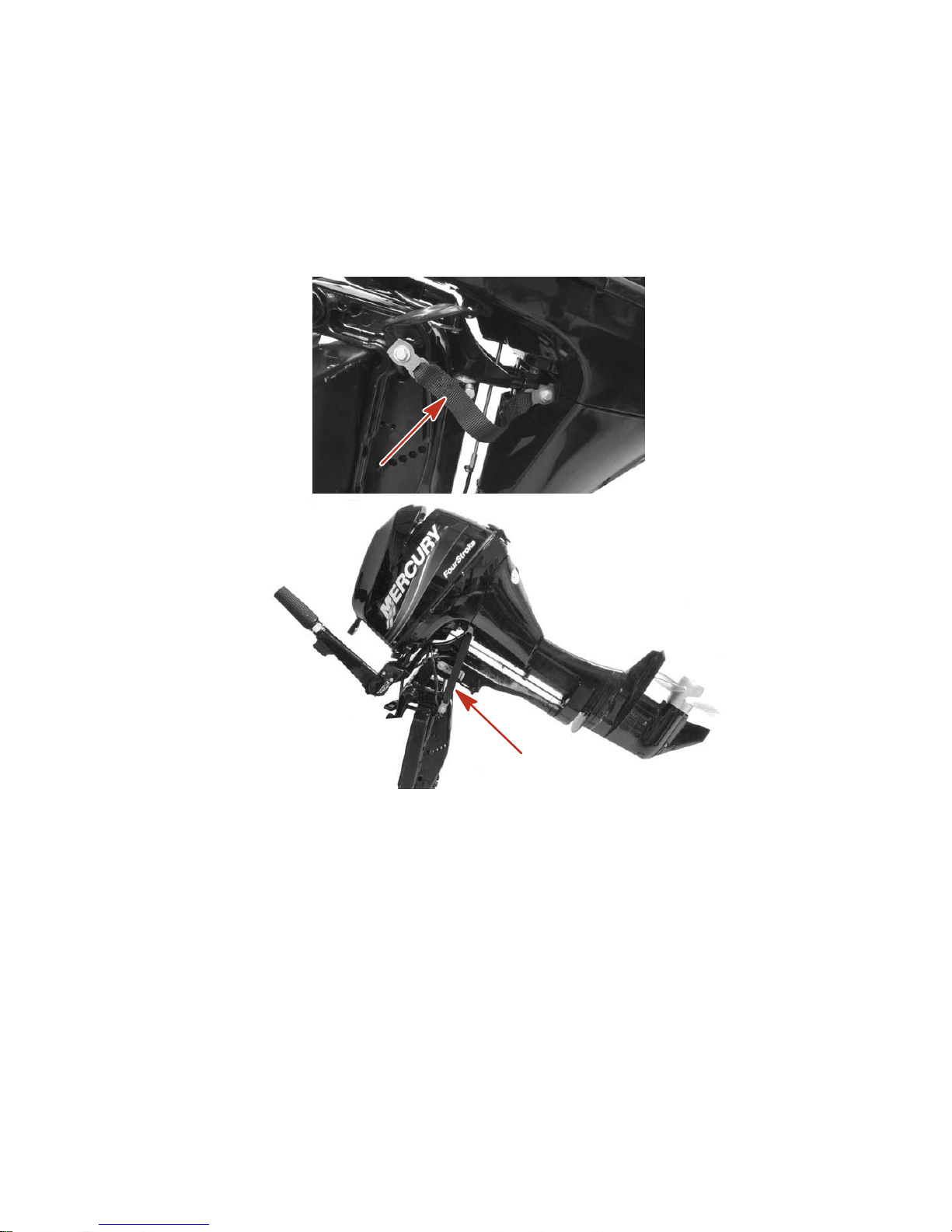
FEATURES AND CONTROLS
53
TILTING OPERATION
To tilt outboard, shut off the engine and press the tilt switch to the
up position. The outboard will tilt up until the switch is released or
it reaches its maximum tilt position. Tiller handle models have a
kicker strap located on each side of the outboard, preventing the
outboard from turning when tilted up.
4676
4678
1. Engage the tilt support lever by rotating lever down.
2. Lower outboard to rest on the tilt support lever.
Page 62

FEATURES AND CONTROLS
54
3. Disengage the tilt support lever, by raising the outboard off the
support lever and lifting the knob. Lower the outboard.
a
b
4650
a - Tilt support lever b - Knob
Setting The Transom Angle Of Your Outboard
The vertical transom angle of your outboard is adjusted by
changing the position of the preset tilt knob in one of the three
adjustment holes provided. Proper adjustment allows the boat to
achieve optimum performance, stability, and minimize steering
effort.
NOTE: Refer to the following lists when adjusting the transom
angle of your outboard.
The preset tilt knob should be adjusted so the outboard is
positioned to run perpendicular to the water when the boat is
running at full speed. This allows the boat to be driven parallel to
the water.
Page 63

FEATURES AND CONTROLS
55
Arrange passengers and load in the boat so the weight is
distributed evenly.
a
b
c
28533
a - Too much angle (stern down ‑ bow up)
b - Not enough angle (stern up ‑ bow down)
c - Angle adjusted properly (bow slightly up)
Consider the following lists carefully when adjusting the operating
angle of your outboard.
Adjusting the outboard close to the boat transom can:
• Lower the bow.
• Result in quicker planing off, especially with a heavy load or a
stern heavy boat.
• Generally improve the ride in choppy water.
• Increase steering torque or pull to the right.
• In excess can lower the bow of some boats to a point where
they begin to plow with their bow in the water while on plane.
This can result in an unexpected turn in either direction (called
bow steering or over‑steering) if any turn is attempted or if a
significant wave is encountered.
Adjusting the outboard away from the boat transom can:
Page 64

FEATURES AND CONTROLS
56
• Lift the bow out of the water.
• Generally increase top speed.
• Increase clearance over submerged objects or a shallow
bottom.
• Increase steering torque or pull to the left at a normal
installation height.
• In excess can cause boat porpoising (bouncing) or propeller
ventilation.
Adjusting Transom Angle
1. Stop the engine. Shift the outboard into forward. Raise the
engine to one of the tilt release positions. Change the preset
knob position and lower the outboard to the preset transom
angle position.
2. Repeat step number one if the transom angle needs further
adjustment.
a
b
28589
a - Transom angle
settings
b - Tilt release position
Shallow Water Operation
There are three (3) shallow water drive positions that enable the
outboard to be tilted up to prevent hitting the bottom.
1. Stop the engine. Shift the outboard into neutral. Tilt the
outboard up to one of the shallow water drive positions.
Ensure the water intake is submerged.
Page 65

FEATURES AND CONTROLS
57
2. To release the shallow water drive, stop engine and tilt
outboard up to one of the tilt release position. Gently lower the
outboard to the preset transom angle.
b
a
c
28592
a - Shallow water drive
positions
b - Tilt release positions
c - Water Intake
Tilting Outboard
1. Stop the engine. Shift the outboard into the forward gear
position.
2. Take hold of the top cowl grip and raise the outboard to the
full up position.
3. Pull out on the tilt lock knob and move it to the lock position.
The outboard cannot be lowered while the tilt lock knob is in
the lock position.
4. To lower the engine, move the tilt lock knob to the unlock
position.
Page 66

FEATURES AND CONTROLS
58
5. Raise the outboard to the tilt release position and gently lower
the outboard to the preset trim position.
c
b
a
28587
a - Tilt lock knob in lock position
b - Tilt lock knob in unlock position
c - Tilt range indicator
Trim Tab Adjustment
Propeller steering torque will cause your boat to pull in one
direction. This steering torque is a normal thing that results from
your outboard not being trimmed so the propeller shaft is parallel
to the water surface. The trim tab can help compensate for this
steering torque in many cases and can be adjusted within limits to
reduce any unequal steering effort.
26816
NOTE: Trim tab adjustment will have little effect reducing steering
torque if the outboard is installed with the anti‑ventilation plate
approximately 50 mm (2 inches) or more above the boat bottom.
Page 67

FEATURES AND CONTROLS
59
Operate your boat at normal cruising speed, trimmed to the desired
position. Turn your boat left and right and note the direction the
boat turns more easily.
If adjustment is necessary, loosen trim tab bolt and make small
adjustments at a time. If the boat turns more easily to the left, move
the trailing edge of trim tab to the left. If the boat turns more easily
to the right move the trailing edge of trim tab to the right. Retighten
bolt and retest.
Page 68

OPERATION
60
Pre‑Starting Check List
• Operator knows safe navigation, boating, and operating
procedures.
• An approved personal flotation device of suitable size for each
person aboard and readily accessible (it is the law).
• A ring type life buoy or buoyant cushion designed to be thrown
to a person in the water.
• Know your boats maximum load capacity. Look at the boat
capacity plate.
• Fuel supply OK.
• Arrange passengers and load in the boat so the weight is
distributed evenly and everyone is seated in a proper seat.
• Tell someone where you are going and when you expect to
return.
• It is illegal to operate a boat while under the influence of
alcohol or drugs.
• Know the waters and area you will be boating; tides, currents,
sand bars, rocks, and other hazards.
• Make inspection checks listed in Maintenance ‑ Inspection
and Maintenance Schedule.
Operating In Freezing Temperatures
When using your outboard or having your outboard moored in
freezing or near freezing temperatures, keep the outboard tilted
down at all times so the gearcase is submerged. This prevents
trapped water in gearcase from freezing and causing possible
damage to the water pump and other components.
If there is a chance of ice forming on the water, the outboard should
be removed and drained completely of water. If ice should form at
the water level inside the outboard driveshaft housing, it will block
water flow to the engine causing possible damage.
Operating In Salt Water Or Polluted Water
We recommend that you flush the internal water passages of your
outboard with fresh water after each use in salt or polluted water.
This will prevent a buildup of deposits from clogging the water
passages. Refer to Maintenance ‑ Flushing The Cooling System.
Page 69

OPERATION
61
If you keep your boat moored in the water, always tilt the outboard
so the gearcase is completely out of water (except in freezing
temperatures) when not in use.
Wash the outboard exterior and flush out the exhaust outlet of the
propeller and gearcase with fresh water after each use. Each
month, spray Mercury Precision or Quicksilver Corrosion Guard on
external metal surfaces. Do not spray on corrosion control anodes
as this will reduce the effectiveness of the anodes.
Operating Outboard As An Auxiliary Engine
If the outboard is used as an auxiliary engine, stop the engine and
tilt the outboard out of the water when using the main power
source.
IMPORTANT: The outboard must be restrained from bouncing
while operating the boat using the main power source. Bouncing
can damage the outboard and boat transom.
Pre‑Starting Instructions
1. Connect the remote fuel line to the outboard. Make sure
connector is snapped into place.
27231
2. Check the engine oil level.
27233
Page 70

OPERATION
62
NOTICE
Failure to provide sufficient cooling water will damage the water
pump and cause the engine to overheat. Provide a sufficient
supply of water at the water inlets during operation.
3. Make sure the cooling water intake is submerged.
26837
Engine Break‑in Procedure
IMPORTANT: Failure to follow the engine break‑in procedures can
result in poor performance throughout the life of the engine and
can cause engine damage. Always follow break‑in procedures.
1. For the first hour of operation, run the engine at varied throttle
settings up to 2000 RPM or at approximately half throttle.
2. For the second hour of operation, run the engine at varied
throttle settings up to 3000 RPM or at three‑quarter throttle,
and at full throttle for approximately one minute every ten
minutes.
3. For the next eight hours of operation, avoid continuous
operation at full throttle for more than five minutes at a time.
Starting the Engine ‑ Tiller Handle Models
Before starting, read the pre‑starting check list, special operating
instructions, and engine break‑in procedure in the Operation
section.
1. Open the fuel tank vent on manual venting type tanks.
19748
Page 71

OPERATION
63
2. Position the fuel line primer bulb so the arrow on the side of
the bulb is pointing up. Squeeze the fuel line primer bulb
several times until it feels firm.
IMPORTANT: To prevent engine flooding, do not squeeze the
primer bulb after engine has warmed up.
27348
3. Set the lanyard stop switch to "RUN" position. Refer to
General Information ‑ Lanyard Stop Switch.
19791
4. Set the tiller handle gear shift to neutral ("N") position.
28577
5. If the engine is cold, press the fuel primer in twice.
IMPORTANT: Avoid engine flooding ‑ Do not press in the fuel
primer if engine is warm. This will inject fuel into the engine and
may cause a hard starting flooded condition.
28548
Page 72
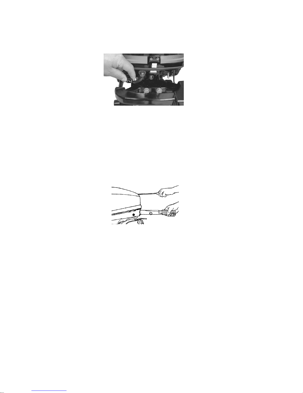
OPERATION
64
6. Cold engine ‑ Pull out the choke knob for starting. Push in the
choke knob after engine starts to warm up.
28544
IMPORTANT: Outboards with battery charging capabilities must
not be operated with battery cables disconnected from the battery.
Damage to the charging system may result.
7. Manual starting models ‑ Pull the starter rope slowly until you
feel the starter engage, then pull rapidly to crank the engine.
Allow rope to return slowly. Repeat until engine starts. After
the engine has started, push in the choke knob.
28586
8. Electric start tiller handle models ‑ Push the starter button and
crank the engine. Release button when the engine starts. Do
not operate the starter motor continuously for longer than ten
seconds at a time. If the engine fails to start, wait 30 seconds
and try again.
Page 73
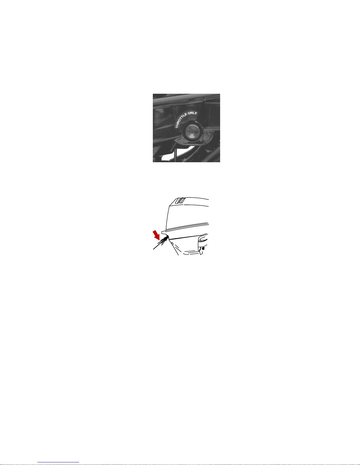
OPERATION
65
9. Flooded engine - If the engine will not start, push in the
throttle only button and advance the throttle grip to fast throttle
speed. Push in the choke knob and retry starting the engine.
After the engine has started, immediately reduce throttle
speed to idle.
28550
10.Check for a steady stream of water flowing out of the water
pump indicator hole.
27240
IMPORTANT: If no water is coming out of the water pump
indicator hole, stop engine and check cooling water intake for
obstruction. No obstruction may indicate a water pump failure or
blockage in the cooling system. These conditions will cause the
engine to overheat. Have the outboard checked by your dealer.
Operating the engine while overheated will cause serious engine
damage.
WARMING UP ENGINE
Before beginning operation, allow the engine to warm up at idling
speed for three minutes.
Starting the Engine ‑ Remote Control Models
Before starting, read the pre‑starting check list, special operating
instructions, and engine break‑in procedure in the Operation
section.
Page 74
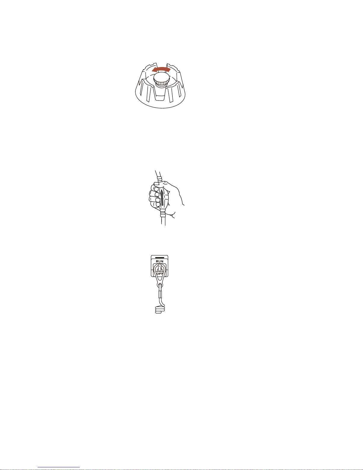
OPERATION
66
1. Open the fuel tank vent screw in the filler cap on manual
venting type tanks.
19748
2. Position the fuel line primer bulb so the arrow on the side of
the bulb is pointing up. Squeeze the fuel line primer bulb
several times until it feels firm.
IMPORTANT: To prevent engine flooding, do not squeeze the
primer bulb after engine has warmed up.
27348
3. Set the lanyard stop switch to "RUN" position. Refer to
General Information ‑ Lanyard Stop Switch.
19791
4. Set the remote control handle to neutral position.
Page 75

OPERATION
67
IMPORTANT: Avoid engine flooding ‑ Do not advance the throttle
while engine is not running. This will inject fuel into the engine and
may cause a hard starting flooded condition.
N
26838
IMPORTANT: Outboards with battery charging capabilities must
not be operated with battery cables disconnected from the battery.
Damage to the charging system may result.
5. Do not use the throttle‑only feature on the remote control for
initial starting. After starting the engine, you can slowly
advance the throttle‑only lever, or press the throttle‑only
button and advance the control handle, to increase idle speed
until the engine is warmed up. Keep engine speed below 2000
RPM.
27242
NOTE: Starting Flooded Engine ‑ lift the neutral fast idle lever to
full up and continue to crank the engine for starting.
Page 76
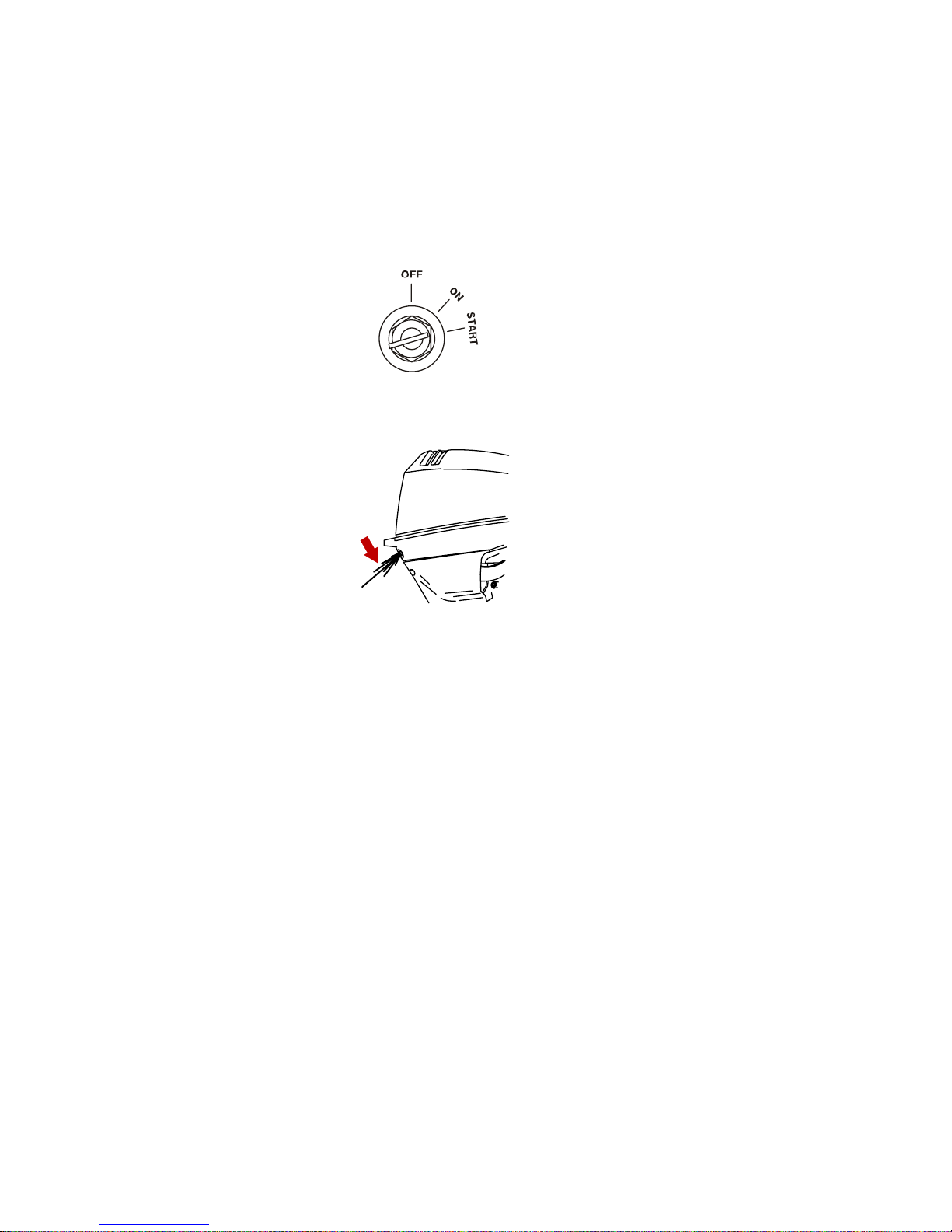
OPERATION
68
6. Turn the ignition key to the "START" position and start the
engine. If the engine is cold, push in on the key to choke the
engine while cranking. If the engine fails to start in ten
seconds, wait 30 seconds and try again. If the engine begins
to stall, re‑choke (push the key in) until the engine is running
smoothly.
19804
7. Check for a steady stream of water flowing out of the water
pump indicator hole.
27240
IMPORTANT: If no water is coming out of the water pump
indicator hole, stop engine and check cooling water intake for
obstruction. No obstruction may indicate a water pump failure or
blockage in the cooling system. These conditions will cause the
engine to overheat. Have the outboard checked by your dealer.
Operating the engine while overheated will cause engine damage.
WARMING UP ENGINE
Before beginning operation, allow the engine to warm up at idling
speed for three minutes.
Starting a Hot Engine
TILLER HANDLE MODELS
1. Pull out the choke knob.
2. Crank the engine with the recoil rope or with the electric start
button.
3. Push in the choke knob after engine has started to warm up.
Page 77
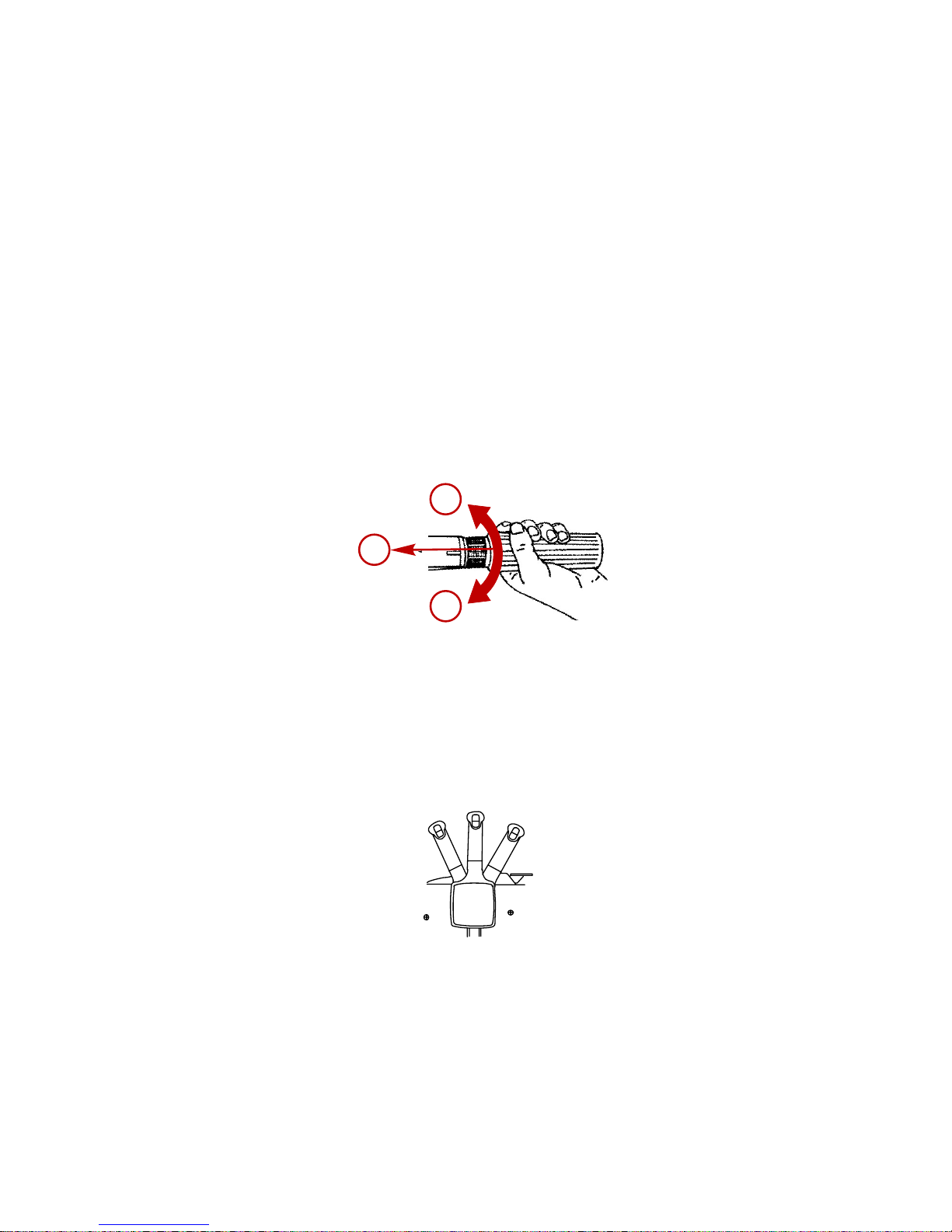
OPERATION
69
REMOTE CONTROL MODELS
1. Crank the engine over while pushing the key in to engage the
choke solenoid.
2. After the engine has started, release the key.
Gear Shifting
IMPORTANT: Never shift outboard into gear unless engine speed
is at idle. Do not shift outboard into reverse when the engine is not
running.
• Your outboard has three gear shift positions to provide
operation: Forward (F), Neutral (N), and Reverse (R).
• Tiller Handle Models ‑ Reduce engine speed to idle before
shifting.
cab
28595
a - (R) Reverse
b - (N) Neutral
c - (F) Forward
• Remote Control Models ‑ When shifting, always stop at
neutral position and allow the engine speed to return to idle.
N
R
27237
• Always shift outboard into gear with a quick motion.
• After shifting outboard into gear, advance the remote control
lever or rotate the throttle grip (tiller handle) to increase speed.
Page 78

OPERATION
70
Stopping The Engine
1. Remote Control Models ‑ Reduce engine speed and shift
outboard to neutral position. Turn ignition key to "OFF"
position.
26843
2. Tiller Handle Models ‑ Reduce engine speed and shift
outboard to neutral position. Push in the engine stop button or
turn ignition key to "OFF" position.
26776
Emergency Starting
If the starter system fails, use the spare starter rope (provided) and
follow this procedure.
!
WARNING
The neutral‑speed‑protection device is inoperative when starting
the engine with the emergency starter rope. Set the engine speed
at idle and the gear shift in neutral to prevent the outboard from
starting in gear.
1. Shift the outboard into neutral.
2. Ensure the lanyard stop switch is in the run position.
3. Remove the top cowl.
Page 79

OPERATION
71
4. Remove the three screws holding the flywheel cover on.
a
b
a
a
c
28614
a - Flywheel cover
screws (3)
b - Recoil neutral
interlock
c - Fuse holder
5. Remove the flywheel cover.
6. Remote Control models ‑ Ensure the key switch is in the "ON"
position.
!
WARNING
High voltage is present any time the key is turned on, especially
when starting or operating the engine. Do not touch ignition
components or metal test probes and stay clear of spark plug
leads when performing live tests.
!
WARNING
The exposed moving flywheel can cause serious injury. Keep
your hands, hair, clothing, tools, and other objects away from
engine when starting or running the engine. Do not attempt to
reinstall the flywheel cover or top cowl when engine is running.
7. Refer to the appropriate starting procedure (cold or hot).
Page 80

OPERATION
72
8. Place the starter rope knot into the flywheel notch and wind
the rope clockwise around the flywheel.
28616
9. Pull the starter rope quickly.
Page 81
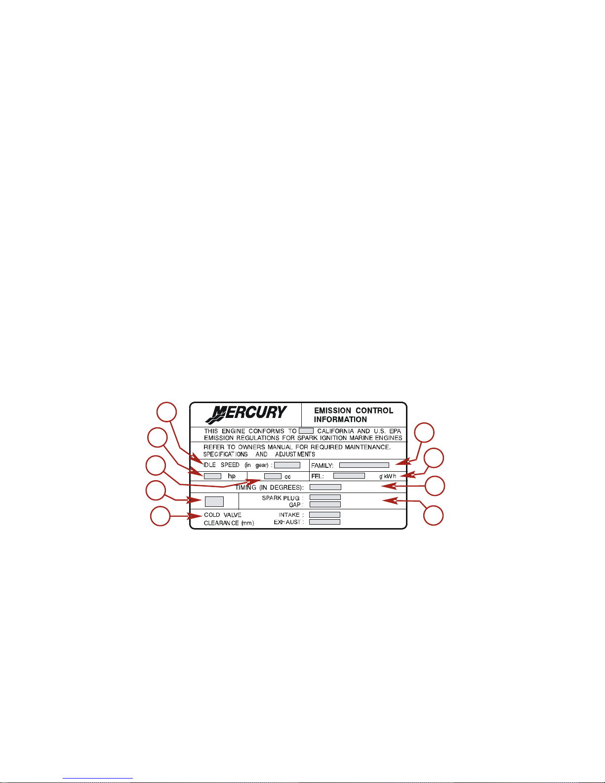
MAINTENANCE
73
Outboard Care
To keep your outboard in the best operating condition, it is
important that your outboard receive the periodic inspections and
maintenance listed in the Inspection and Maintenance
Schedule. We urge you to keep it maintained properly to ensure
the safety of you and your passengers, and retain its dependability.
Record maintenance performed in the Maintenance Log at the
back of this book. Save all maintenance work orders and receipts.
SELECTING REPLACEMENT PARTS FOR YOUR
OUTBOARD
We recommend using original Mercury Precision or Quicksilver
replacement parts and Genuine Lubricants.
EPA Emissions
EMISSION CERTIFICATION LABEL
An emission certification label, showing emission levels and
engine specifications directly related to emissions, is placed on the
engine at time of manufacture.
e
d
c
b
a
f
g
h
i
21096
a - Idle speed
b - Engine horsepower
c - Piston displacement
d - Part number
e - Valve clearance (if
applicable)
f - Family number
g - Maximum emission
output for the engine
family
h - Timing specification
i - Recommended spark
plug and gap
Page 82

MAINTENANCE
74
OWNER RESPONSIBILITY
The owner/operator is required to have routine engine
maintenance performed to maintain emission levels within
prescribed certification standards.
The owner/operator is not to modify the engine in any manner that
would alter the horsepower or allow emissions levels to exceed
their predetermined factory specifications.
Inspection And Maintenance Schedule
BEFORE EACH USE
• Check engine oil level. See Fuel & Oil ‑ Checking and Adding
Engine Oil.
• Check that lanyard stop switch stops the engine.
• Visually inspect the fuel system for deterioration or leaks.
• Check outboard for tightness on transom.
• Check steering system for binding or loose components.
• Remote Control Models ‑ Visually check steering link rod
fasteners for proper tightness. See Steering Link Rod
Fasteners.
• Check propeller blades for damage.
AFTER EACH USE
• Flush out the outboard cooling system if operating in salt or
polluted water. See Flushing the Cooling System.
• Wash off all salt deposits and flush out the exhaust outlet of
the propeller and gearcase with fresh water if operating in salt
water.
EVERY 100 HOURS OF USE OR ONCE YEARLY,
WHICHEVER OCCURS FIRST
• Lubricate all lubrication points. Lubricate more frequently
when used in salt water. See Lubrication Points.
• Change engine oil and replace the oil filter. The oil should be
changed more often when the engine is operated under
adverse conditions such as extended trolling. See Changing
Engine Oil.
Page 83

MAINTENANCE
75
• Replace spark plugs at first 100 hours or first year. After that,
inspect spark plugs every 100 hours or once yearly. Replace
spark plugs as needed. See Spark Plug Inspection and
Replacement.
• Inspect thermostat visually for corrosion and broken spring.
Make sure thermostat closes completely at room temperature.
1.
• Check fuel line filter for contaminants. See Fuel System.
• Check corrosion control anodes. Check more frequently when
used in salt water. See Corrosion Control Anode.
•
Check and adjust valve clearance, if necessary.
1.
• Drain and replace gearcase lubricant. See Gearcase
Lubrication.
• Check power tilt fluid. See Checking Power Tilt Fluid.
•
Lubricate splines on the driveshaft.
1.
•
Remote control models ‑ Check control cable adjustments.
1.
• Inspect timing belt. See Timing Belt Inspection.
• Check tightness of bolts, nuts, and other fasteners.
• Check cowl seals to make sure seals are intact and not
damaged.
• Check internal cowl sound reduction foam (if equipped) to
make sure foam is intact and not damaged.
• Check that the intake silencer (if equipped) is in place.
• Check that the idle relief muffler (if equipped) is in place.
• Check for loose hose clamps and rubber boots (if equipped)
on the air intake assembly.
EVERY 300 HOURS OF USE OR THREE YEARS
• Replace water pump impeller (more often if overheating
occurs or reduced water pressure is noted).
1.
BEFORE PERIODS OF STORAGE
• Refer to Storage procedure. See Storage section.
1. These items should be serviced by an authorized dealer.
Page 84
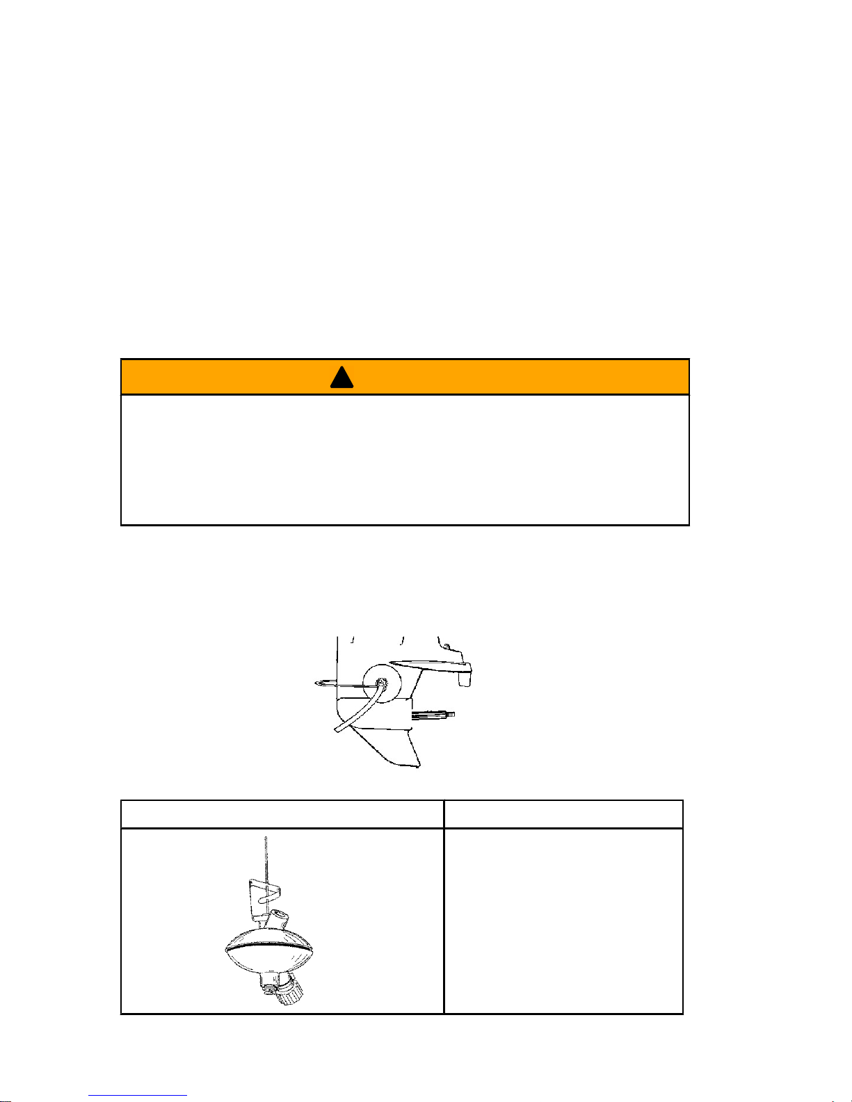
MAINTENANCE
76
Flushing the Cooling System
Flush the internal water passages of the outboard with fresh water
after each use in salt, polluted, or muddy water. This will help
prevent a buildup of deposits from clogging the internal water
passages.
Use a Mercury Precision or Quicksilver accessory (or equivalent)
flushing attachment.
IMPORTANT: The engine must be run during flushing in order to
open the thermostat and circulate water through the water
passages.
!
WARNING
Rotating propellers can cause serious injury or death. Never
operate the boat out of the water with a propeller installed. Before
installing or removing a propeller, place the drive unit in neutral
and engage the lanyard stop switch to prevent the engine from
starting.
1. Remove propeller. Refer to Propeller Replacement. Install the
flushing attachment so the rubber cups fit tightly over the
cooling water intake.
27256
Flushing Device 91‑44357Q 2
9192
Attaches to the water intakes;
provides a fresh water
connection when flushing the
cooling system or operating the
engine.
Page 85

MAINTENANCE
77
2. Attach a water hose to the flushing attachment. Turn on the
water and adjust the flow so water is leaking around the rubber
cups to ensure the engine receives an adequate supply of
cooling water.
27259
3. Start the engine and run it at idle speed in neutral shift position.
IMPORTANT: Do not run engine above idle when flushing.
4. Adjust water flow (if necessary) so excess water continues
leaking out from around the rubber cups to ensure the engine
is receiving an adequate supply of cooling water.
27260
5. Check for a steady stream of water flowing out of the water
pump indicator hole. Continue flushing the outboard for 3 to 5
minutes, carefully monitoring water supply at all times.
6. Stop the engine, turn off the water, and remove the flushing
attachment. Reinstall the propeller.
Page 86

MAINTENANCE
78
Top Cowl Removal And Installation
REMOVAL
1. Pull out the front cowl latch.
4936
2. Lift front of cowl to clear front latch and push toward the rear
to clear rear hook.
3. Lift top cowl to remove.
INSTALLATION
1. Lower top cowl into position over engine.
2. Move the cowl toward the rear to align rear hook. After rear
hook has engaged, move cowl toward front and push down
front of cowl.
3. Push in latch to secure top cowl.
Battery Inspection
The battery should be inspected at periodic intervals to ensure
proper engine starting capability.
IMPORTANT: Read the safety and maintenance instructions
which accompany your battery.
1. Turn off the engine before servicing the battery.
2. Add water as necessary to keep the battery full.
3. Make sure the battery is secure against movement.
4. Battery cable terminals should be clean, tight, and correctly
installed. Positive to positive and negative to negative.
5. Make sure the battery is equipped with a non‑conductive
shield to prevent accidental shorting of battery terminals.
Page 87

MAINTENANCE
79
Exterior Care
Your outboard is protected with a durable baked enamel finish.
Clean and wax often using marine cleaners and waxes.
Fuel System
!
WARNING
Fuel is flammable and explosive. Ensure the key switch is off and
the lanyard is positioned so that the engine cannot start. Do not
smoke or allow sources of spark or open flame in the area while
servicing. Keep the work area well ventilated and avoid
prolonged exposure to vapors. Always check for leaks before
attempting to start the engine and wipe up any spilled fuel
immediately.
Before servicing any part of the fuel system, stop engine and
disconnect the battery. Drain the fuel system completely. Use an
approved container to collect and store fuel. Wipe up any spillage
immediately. Material used to contain spillage must be disposed
of in an approved receptacle. Any fuel system service must be
performed in a well ventilated area. Inspect any completed service
work for sign of fuel leakage.
FUEL LINE INSPECTION
Visually inspect the fuel line and primer bulb for cracks, swelling,
leaks, hardness, or other signs of deterioration or damage. If any
of these conditions are found, the fuel line or primer bulb must be
replaced.
Page 88

MAINTENANCE
80
FUEL LINE FILTER
Inspect the fuel line filter. If the filter appears to be contaminated,
remove and replace.
28620
IMPORTANT: Visually inspect for fuel leakage from the filter
connections by squeezing the primer bulb until firm, forcing fuel
into the filter.
Steering Link Rod Fasteners
IMPORTANT: The steering link rod that connects the steering
cable to the engine must be fastened using the steering link rod
fastening hardware supplied with engine. Never replace the
locknuts (11‑16147‑‑3) with common nuts (non‑locking) as they
will work loose and vibrate off, freeing the link rod to disengage.
Page 89
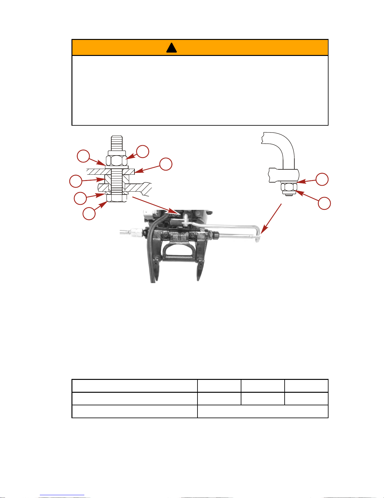
MAINTENANCE
81
!
WARNING
Improper fasteners or improper installation procedures can result
in loosening or disengagement of the steering link rod. This can
cause a sudden, unexpected loss of boat control, resulting in
serious injury or death due to occupants being thrown within or
out of the boat. Always use required components and follow
instructions and torque procedures.
a
b
b
c
d
b
f
e
10352
a - Bolt (12‑71970)
b - Flat washer
c - Spacer
d - Nylon insert locknut (11‑16147‑‑3)
e - Steering bracket ‑ Install steering link rod into side hole
f - Nylon insert locknut (11‑16147‑‑3) (tighten until seats
then back off 1/4 turn)
Description Nm lb. in. lb. ft.
Nylon insert locknut "d" 27 20
Nylon insert locknut "f" Tighten until seats, then back off 1/4 turn
Assemble steering link rod to steering cable with flat washer and
nylon insert locknut. Tighten locknut until it seats, then back nut off
1/4 turn.
Page 90
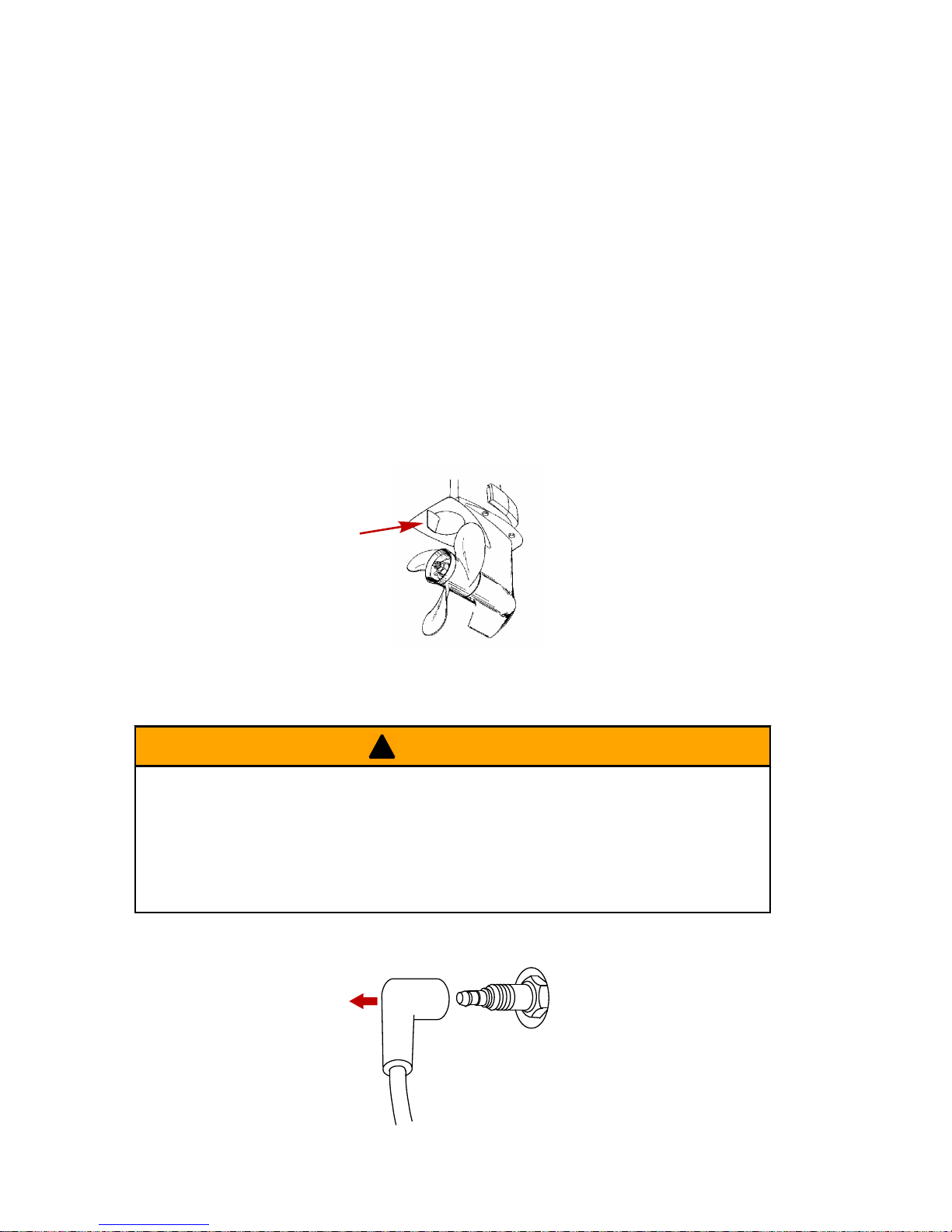
MAINTENANCE
82
Assemble steering link rod to engine with bolt, locknut and spacer
and flat washers. Torque locknut to specifications.
Corrosion Control Anode
Your outboard has a corrosion control anode installed to the
gearcase. An anode helps protect the outboard against galvanic
corrosion by sacrificing its metal to be slowly corroded instead of
the outboard metals.
The anode requires periodic inspection especially in salt water
which will accelerate the erosion. To maintain this corrosion
protection, always replace the anode before it is completely
eroded. Never paint or apply a protective coating on the anode as
this will reduce effectiveness of the anode.
28623
Propeller Replacement
!
WARNING
Rotating propellers can cause serious injury or death. Never
operate the boat out of the water with a propeller installed. Before
installing or removing a propeller, place the drive unit in neutral
and engage the lanyard stop switch to prevent the engine from
starting.
1. Remove the spark plug lead to prevent engine from starting.
26899
Page 91

MAINTENANCE
83
2. Move gear shift lever into neutral (N).
N
26838
cab
28595
a - Reverse
b - Neutral
c - Forward
3. Straighten and remove cotter pin.
4. Place a block of wood between gearcase and propeller to hold
propeller and remove propeller nut.
5. Pull propeller straight off shaft. If propeller is seized to the shaft
and cannot be removed, have the propeller removed by an
authorized dealer.
IMPORTANT: To prevent the propeller hub from corroding and
seizing to the propeller shaft (especially in salt water), always
apply a coat of the recommended lubricant to the entire propeller
shaft at the recommended maintenance intervals and also each
time the propeller is removed.
6. Coat the propeller shaft with Quicksilver or Mercury Precision
Lubricants Anti‑Corrosion Grease or 2‑4‑C with Teflon.
27095
Tube Ref No. Description Where Used Part No.
94
Anti-Corrosion
Grease
Propeller shaft
92-802867Q
1
Page 92

MAINTENANCE
84
Tube Ref No. Description Where Used Part No.
95
2-4-C with Teflon Propeller shaft 92-802859A1
7. Install front thrust washer, propeller, rear thrust hub, and
propeller nut onto the shaft.
8. Place a block of wood between gearcase and propeller to
prevent rotation and tighten propeller nut. Secure propeller nut
to the shaft with cotter pin.
a
b
c
d
e
27094
a - Cotter pin
b - Propeller nut
c - Rear thrust washer
d - Propeller
e - Front thrust washer
Fuse Replacement ‑ Electric Start Models
IMPORTANT: Always carry spare 20 AMP fuses.
Page 93

MAINTENANCE
85
The electric starting circuit is protected from overload by a 20 AMP
fuse. If the fuse is blown try to locate and correct the cause of the
overload. If the cause is not found, the fuse may blow again.
a
b
28618
a - Spare fuse b - Circuit protecting fuse
1. Open the fuse holder and look at the silver colored band inside
the fuse. If band is broken, replace the fuse. Replace fuse with
a new fuse with the same rating.
a
b
28619
Identifying a blown fuse
a - Good fuse b - Blown fuse
Spark Plug Inspection And Replacement
!
WARNING
Damaged spark plug boots may emit sparks which can ignite fuel
vapors under the engine cowl, resulting in serious injury or death
from a fire or explosion. To avoid damaging the spark plug boots,
do not use any sharp object or metal tool to remove the spark
plug boots.
Page 94
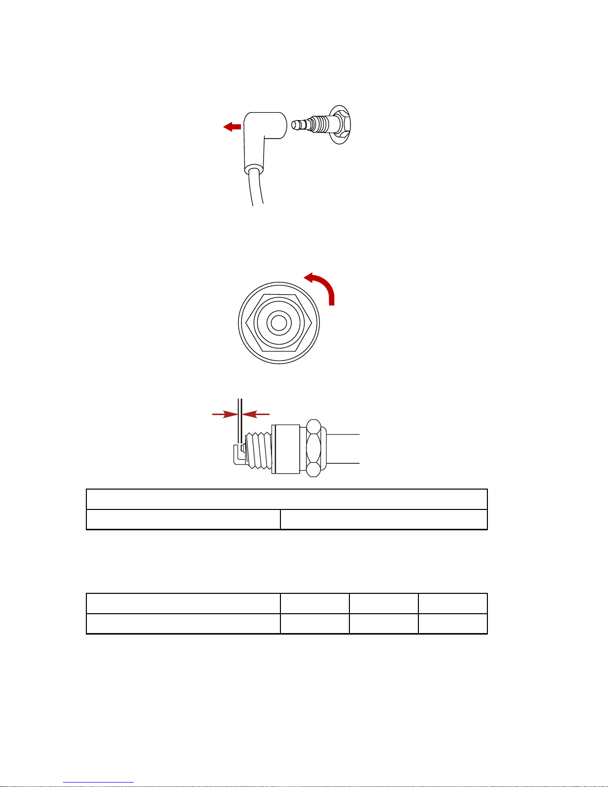
MAINTENANCE
86
1. Remove the spark plug boots. Twist the rubber boots slightly
and pull off.
26899
2. Remove the spark plugs to inspect. Replace spark plug if
electrode is worn or the insulator is rough, cracked, broken,
blistered or fouled.
26946
3. Set the spark plug gap to specification.
26947
Spark Plug
Spark plug gap 1.0 mm (0.040 in.)
4. Before installing spark plugs, clean off any dirt on the spark
plug seats. Install plugs finger tight, and then tighten 1/4 turn
or torque to specifications.
Description Nm lb. in. lb. ft.
Spark plug 27 20
Timing Belt Inspection
1. Inspect the timing belt and have it replaced by an authorized
dealer if any of the following conditions are found.
a. Cracks in the back of the belt or in the base of the belt teeth.
Page 95
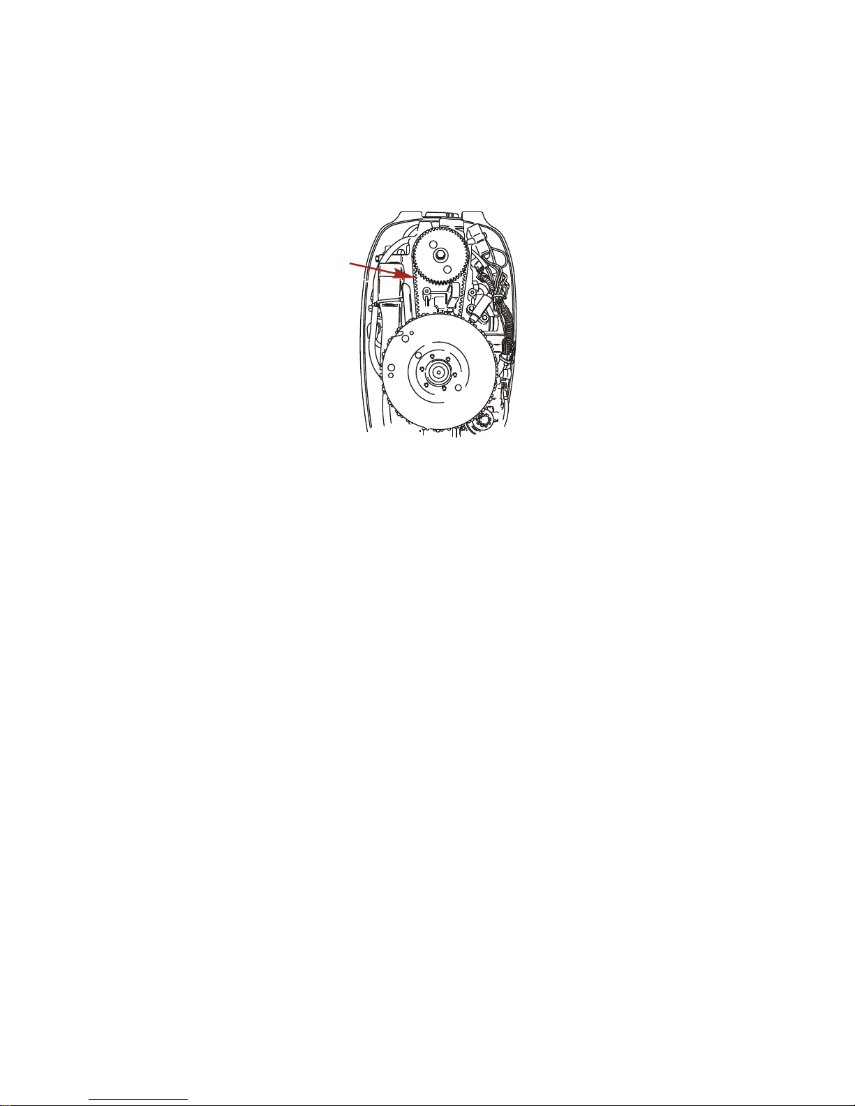
MAINTENANCE
87
b. Excessive wear at the roots of the cogs.
c. Rubber portion swollen by oil.
d. Belt surfaces roughened.
e. Signs of wear on edges or outer surfaces of belt.
27578
Changing Engine Oil
ENGINE OIL CAPACITY
Engine oil capacity is approximately 800 ml (27 fl. oz.).
OIL CHANGING PROCEDURE
1. Lock the outboard in the full tilt up position.
2. Position outboard so the drain hole is facing downward.
3. Remove drain plug and drain engine oil into an appropriate
container.
IMPORTANT: Do not use a crankcase oil pump when changing
the oil or engine damage may occur.
4. After the initial oil has been drained, temporarily reinstall the
drain plug. Disengage the tilt lock and lower the outboard. Wait
a minute to allow the remaining oil that was trapped in the
engine to return to the drain. Return outboard to the full tilt
position and drain the remaining oil.
Page 96
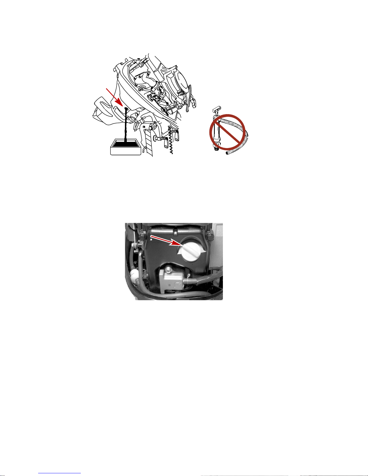
MAINTENANCE
88
5. Lubricate the seal on the drain plug with oil and reinstall.
22921
4537
OIL FILLING
IMPORTANT: Do not overfill. Be sure that the outboard is upright
(not tilted) when checking oil.
1. Remove the oil fill cap and refill with 800 ml (27.0 fl. oz.) of oil.
Reinstall the oil fill cap.
28617
2. Idle engine for five minutes and check for leaks. Stop engine
and check oil level on dipstick. Add oil if necessary.
Lubrication Points
1. Lubricate the following with Quicksilver or Mercury Precision
Lubricants 2‑4‑C with Teflon or Special Lubricant 101.
Page 97

MAINTENANCE
89
Tube Ref No. Description Where Used Part No.
34
Special Lubricant 101
Swivel bracket,
transom clamp
screws, tilt tube,
throttle/shift cables,
steering cable grease
fitting
92-802865Q0
2
95
2-4-C with Teflon
Swivel bracket,
transom clamp
screws, tilt tube,
throttle/shift cables,
steering cable grease
fitting
92-802859A1
• Swivel Bracket ‑ Lubricate fitting.
• Transom Clamp Screws ‑ Lubricate threads.
• Tilt Tube ‑ Lubricate fittings.
a
b
c
28622
a - Tilt tube grease fitting
b - Swivel bracket grease
fitting
c - Transom clamp screws
Page 98

MAINTENANCE
90
• Lubricate the throttle and shift cable moving components,
pivot locations, and shift detent.
a
b
28621
a - Throttle/shift cables b - Shift detent
• Steering Cable Grease Fitting (If Equipped) ‑ Rotate
steering wheel to fully retract the steering cable end into
the outboard tilt tube. Lubricate through fitting.
a
b
27351
a - Steering cable grease fitting
b - Steering cable end
!
WARNING
Incorrect cable lubrication can cause hydraulic lock, leading to
serious injury or death from loss of boat control. Completely
retract the end of the steering cable before applying lubricant.
2. Lubricate the following with Light Weight Oil.
Page 99
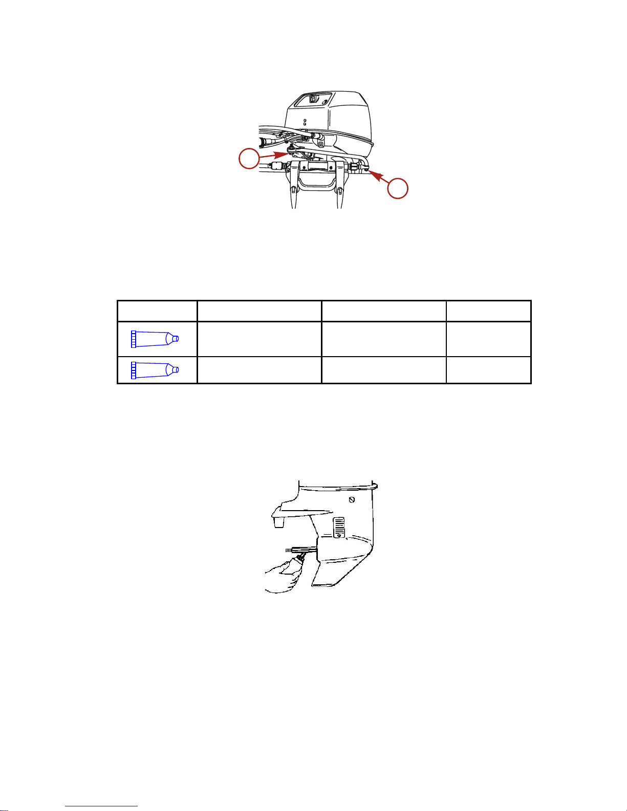
MAINTENANCE
91
• Steering Link Rod Pivot Points ‑ Lubricate points.
a
a
27352
a - Steering link rod pivot points
3. Lubricate the following with Quicksilver or Mercury Precision
Lubricants Anti‑Corrosion Grease or 2‑4‑C with Teflon.
Tube Ref No. Description Where Used Part No.
94
Anti-Corrosion
Grease
Propeller shaft
92-802867Q
1
95
2-4-C with Teflon Propeller shaft 92-802859A1
• Propeller Shaft ‑ Refer to Propeller Replacement for
removal and installation of the propeller. Coat the entire
propeller shaft with lubricant to prevent the propeller hub
from corroding to the shaft.
27344
Page 100

MAINTENANCE
92
Gearcase Lubrication
When adding or changing gearcase lubricant, visually check for
the presence of water in the lubricant. If water is present, it may
have settled to the bottom and will drain out prior to the lubricant,
or it may be mixed with the lubricant, giving it a milky colored
appearance. If water is noticed, have the gearcase checked by
your dealer. Water in the lubricant may result in premature bearing
failure or, in freezing temperatures, will turn to ice and damage the
gearcase.
Remove the fill/drain plug and examine the lubricant draining from
the gearcase for metal particles. A small amount of metal filings or
fine metal particles indicates normal gear wear. An excessive
amount of metal filings or larger particles (chips) may indicate
abnormal gear wear and should be checked by an authorized
dealer.
DRAINING GEARCASE
1. Place outboard in a vertical operating position.
2. Place drain pan below outboard.
3. Remove fill/drain plug and vent plug and drain lubricant.
a
b
28652
a - Vent plug b - Fill/drain plug
GEARCASE LUBRICANT CAPACITY
Standard model gearcase: Approximately 320 ml (10.8 fl. oz.).
Bigfoot model gearcase: Approximately 370 ml (12.5 fl. oz.).
 Loading...