

Page 1

Number 28
Printed in U.S.A. 90-863160 MA Y 2000
2000, Mercury Marine
BRAVO STERNDRIVES
SERVICE
MANUAL
Page 2

90- i
MerCruiser #28 Bravo Sterndrives
90-863160
MerCruiser #28 Bravo Sterndrives
90-863160
Page 3
90-863160 MAY 2000 Page i
Notice
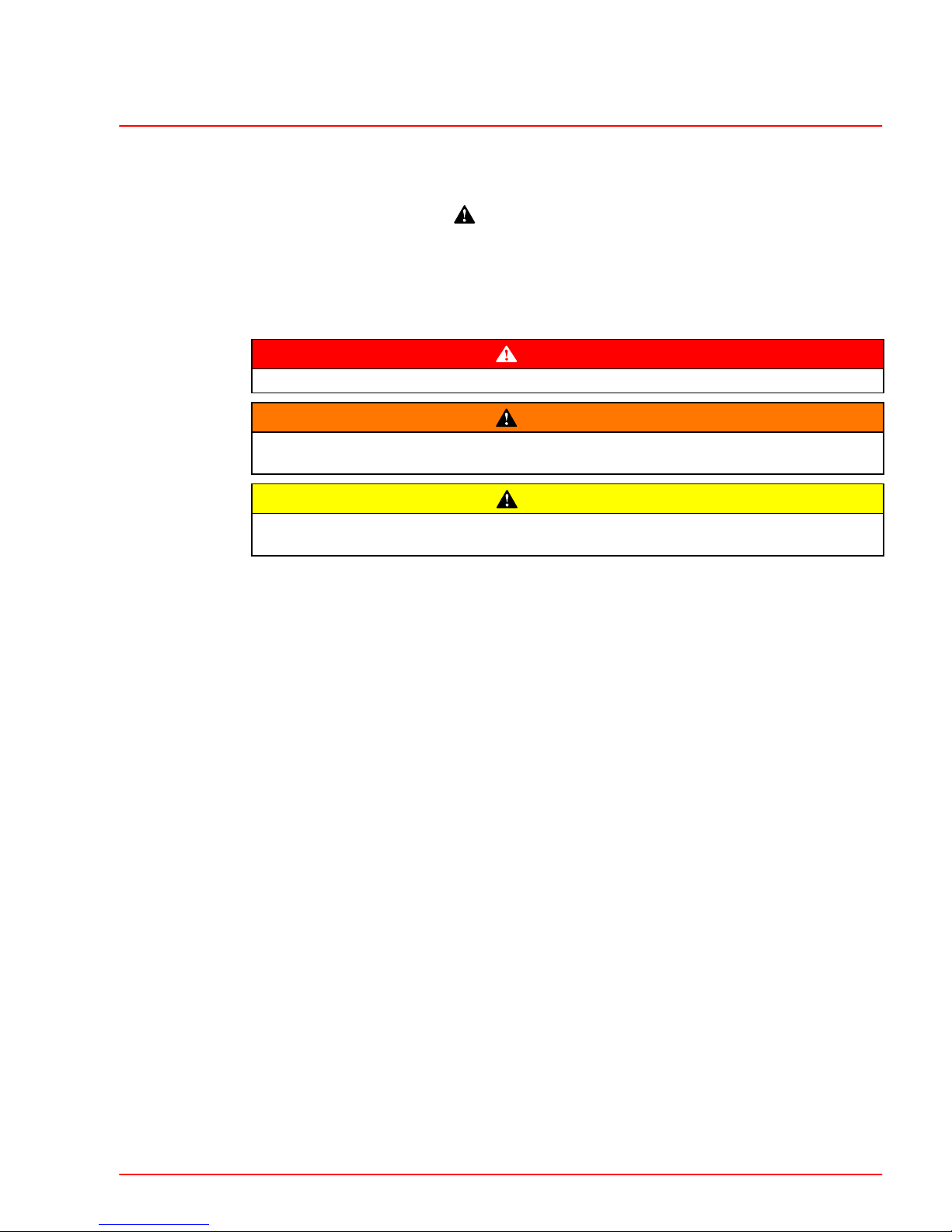
Throughout this publication, “Dangers,” “Warnings” and “Cautions” (accompanied by the International HAZARD Symbol
) are used to alert the mechanic to special instructions concerning a particular service or operation that may be hazardous if performed incorrectly or
carelessly. OBSERVE THEM CAREFULLY!
These “Safety Alerts” alone cannot eliminate the hazards that they signal. Strict compliance
to these special instructions when performing the service, plus “Common Sense” operation,
are major accident prevention measures.
DANGER
DANGER - Immediate hazards which WILL result in severe personal injury or death.
WARNING
WARNING - Hazards or unsafe practices which COULD result in severe personal i n jury or death.
CAUTION
Hazards or unsafe practices which could result in minor personal injury or product
or property damage.
Notice to Users of This Manual
This service manual has been written and published by the Service Department of Mercury
Marine to aid our dealers’ mechanics and company service personnel when servicing the
products described herein.
It is assumed that these personnel are familiar with the servicing procedures of these products, or like or similar products manufactured and marketed by Mercury Marine, that they
have been trained in the recommended servicing procedures of these products which includes the use of mechanics’ common hand tools and the special Mercury Marine or recommended tools from other suppliers.
We could not possibly know of and advise the service trade of all conceivable procedures
by which a service might be performed and of the possible hazards and/or results of each
method. We have not undertaken any such wide evaluation. Therefore, anyone who uses
a service procedure and/or tool, which is not recommended by the manufacturer, first must
completely satisf y h i m s e l f t h a t n e i t h e r h i s n o r t h e p r o d u c t s s a f e t y w i l l b e e ndangered by the
service procedure selected.
All information, illustrations and specifications contained in this manual are based on the
latest product information available at the time of publication. As required, revisions to this
manual will be sent to all dealers contracted by us to sell and/or service these products.
It should be kept in mind, while working on the product, that the electrical system and ignition
system are capable of violent and damaging short circuits or severe electrical shocks. When
performing any work where electrical terminals could possibly be grounded or touched by
the mechanic, the battery cables should be disconnected at the battery.
Any time the intake or exhaust openings are exposed during service they should be covered
to protect against accidental entrance of foreign material which could enter the cylinders and
cause extensive internal damage when the engine is started.
Page 4

Page ii 90-863160 MAY 2000
It is important to note, during any maintenance procedure replacement fasteners must have
the same measurements and strength as those removed. Numbers on the heads of the metric bolts and on the surfaces of metric nuts indicate their strength. American bolts use radial
lines for this purpose, while most American nuts do not have strength markings. Mismatched or incorrect fasteners can result in damage or malfunction, or possibly personal
injury. Therefore, fasteners removed should be saved for reuse in the same locations whenever possible. Where the fasteners are not satisfactory for re-use, care should be taken to
select a replacement that matches the original.
We reserve the right to make changes to this manual without prior notification.
Refer to dealer service bulletins for other pertinent information concerning the products
described in this manual.
Engine Mechanical Components
Many of the engine mechanical components are designed for marine applications. Unlike
automotive engines, marine engines are subjected to extended periods of heavy load
and wide-open-throttle operation and, therefore, require heavy-duty components. Special
marine engine parts have design and manufacturing specifications which are required to
provide long life and dependable performance. Marine engine parts also must be able to
resist the corrosive action of salt or brackish water that will rust or corrode standard automotive parts within a short period of time.
Failure to use recommended Quicksilver service replacement parts can result in poor engine performance and/or durability, rapid corrosion of parts subjected to salt water and
possibly complete failure of the engine.
Use of parts other than recommended service replacement parts, will void the warranty on
those parts which are damaged as a result of the use of other than recommended replacement parts.
Replacement Parts
WARNING
Electrical, ignition and fuel system components on MerCruiser Engines and Sterndrives are designed and manufactured to comply with U.S. Coast Guard Rules
and Regulations to minimize risks of fire or explosion.
Use of replacement electrical, ignition or fuel system components, which do not
comply to th e s e rules and regulations, could result in a fire or explosion hazard and
should be avoided.
When servicing the electrical, ignition and fuel systems, it is extremely important
that all components are properly installed and tightened. If not, any electrical or ignition component opening would permit sparks to ignite fuel vapors from fuel system leaks, if they existed.
Page 5

1
2
3
4
5
6
7
8
Important Information
Removal, Installation and
Adjustment
Sterndrive Unit
Transom Assembly
Power Trim
Steering Systems
Corrosion Protection
Drives
90-863160 MAY 2000 Page iii
Service Manual Outline
Section 1 - Important Information
A - General Information
B - Maintenance
C - Troubleshooting
Section 2 - Removal, Installation and Adjustment
A - All Models
Section 3 - Sterndrive Unit
A - Drive Shaft Housing
B - Gear Housing - Bravo One
C - Gear Housing - Bravo Two
D - Gear Housing - Bravo Three
Section 4 - Transom Assembly
A - Service Procedures Requiring Minor Disassembly
B - Service Procedures Requiring Major Disassembly
Section 5 - Power Trim
A - Oildyne Power Trim Pump
B - Trim Cylinders
C - Dual Power Trim Control
D - Auto Trim II
Section 6 - Steering Systems
A - Power Steering
B - Compact Hydraulic Steering
Section 7 - Corrosion Protection
A - All Models
Section 8 - Drives
A - All Models
Page 6

Page iv 90-863160 MAY 2000
Table of Contents
IMPORTANT INFORMATION
Section 1A - General Information
How To Use This Manual 1A-2. . . . . . . . . . . . . . .
Page Numbering 1A-2. . . . . . . . . . . . . . . . . . .
How to Read a Parts Manual 1A-3. . . . . . . . . . .
Introduction 1A-4. . . . . . . . . . . . . . . . . . . . . . . . . . .
Directional References 1A-4. . . . . . . . . . . . . . . . .
Propeller Rotation 1A-4. . . . . . . . . . . . . . . . . . . . .
Sterndrive Unit 10-Hour Break-In Period
(New or With Replacement Gears) 1A-5. . . . . .
Serial Number Locations and Engine
Designation Decal 1A-5. . . . . . . . . . . . . . . . . . . .
Section 1B - Maintenance
Lubricants / Sealants / Adhesives 1B-2. . . . . . .
Maintenance Schedules 1B-3. . . . . . . . . . . . . . . .
Maintenance Intervals 1B-3. . . . . . . . . . . . . . .
Gas Sterndrive 1B-3. . . . . . . . . . . . . . . . . . . . . . . .
Routine Maintenance * 1B-3. . . . . . . . . . . . . .
Gas Sterndrive(Continued) 1B-4. . . . . . . . . . . . .
Scheduled Maintenance * 1B-4. . . . . . . . . . . .
Specifications 1B-5. . . . . . . . . . . . . . . . . . . . . . . . .
Torque Specification 1B-5. . . . . . . . . . . . . . . . . . .
Fluid Capacities 1B-5. . . . . . . . . . . . . . . . . . . . . . .
Lubrication 1B-5. . . . . . . . . . . . . . . . . . . . . . . . . . .
Shift Cable Pivot Points 1B-5. . . . . . . . . . . . . .
Propeller Shaft 1B-6. . . . . . . . . . . . . . . . . . . . .
Steering System 1B-6. . . . . . . . . . . . . . . . . . . .
Tie Bar Pivot Points 1B-7. . . . . . . . . . . . . . . . .
Transom Gimbal Housing Assembly Swivel
Shaft and Gimbal Bearing 1B-7. . . . . . . . . . . .
Checking and Adding Sterndrive Oil 1B-8. . . . .
Inspection 1B-9. . . . . . . . . . . . . . . . . . . . . . . . .
Changing Sterndrive Oil 1B-10. . . . . . . . . . . . . . .
General Maintenance 1B-12. . . . . . . . . . . . . . . . .
Maintaining Power Package Exterior Sur-
faces 1B-12. . . . . . . . . . . . . . . . . . . . . . . . . . . . .
Steering Head and Remote Control Mainte-
nance 1B-12. . . . . . . . . . . . . . . . . . . . . . . . . . . .
Checking Quicksilver MerCathode System . .
1B-12
Maintaining Anodic Plate 1B-12. . . . . . . . . . .
Boat Bottom Care 1B-12. . . . . . . . . . . . . . . . .
Anti-fouling Paint 1B-12. . . . . . . . . . . . . . . . . .
Maintaining Ground Circuit Continuity 1B-13
Power Package Layup 1B-13. . . . . . . . . . . . . . . .
Engine 1B-13. . . . . . . . . . . . . . . . . . . . . . . . . . .
Sterndrive 1B-13. . . . . . . . . . . . . . . . . . . . . . . .
Power Package Recommissioning 1B-14. . . . . .
Engine 1B-14. . . . . . . . . . . . . . . . . . . . . . . . . . .
Sterndrive 1B-14. . . . . . . . . . . . . . . . . . . . . . . .
Section 1C - Troubleshooting
Table of Contents 1C-1. . . . . . . . . . . . . . . . . . . . .
Troubleshooting 1C-2. . . . . . . . . . . . . . . . . . . . . . .
Sterndrive Unit Troubleshooting 1C-2. . . . . . . . .
Sterndrive Unit Will Not Slide Into
Bell Housing 1C-2. . . . . . . . . . . . . . . . . . . . . . .
Drive Unit Does Not Shift Into Gear;
Remote Control Shift Handle Moves 1C-2. .
Drive Unit Does Not Shift Into Gear;
Remote Control Shift Handle Does
Not Move 1C-3. . . . . . . . . . . . . . . . . . . . . . . . .
Drive Unit Shifts Hard 1C-3. . . . . . . . . . . . . . .
Drive Unit In Gear, Will Not Shift
Out Of Gear 1C-3. . . . . . . . . . . . . . . . . . . . . . .
Gear Housing Noise 1C-4. . . . . . . . . . . . . . . .
Drive Shaft Housing Noise 1C-4. . . . . . . . . . .
Drive Shaft Housing Noise
(Continued) 1C-5. . . . . . . . . . . . . . . . . . . . . . .
Drive Shaft Housing Noise
(Continued) 1C-6. . . . . . . . . . . . . . . . . . . . . . .
Power Shift 1C-7. . . . . . . . . . . . . . . . . . . . . . . . . . .
System Does Not React 1C-7. . . . . . . . . . . . .
System Binds 1C-7. . . . . . . . . . . . . . . . . . . . . .
Performance Troubleshooting 1C-8. . . . . . . . . . .
Low WOT Engine RPM 1C-8. . . . . . . . . . . . . .
High WOT Engine RPM 1C-8. . . . . . . . . . . . .
Propeller Ventilating/Cavitating 1C-8. . . . . . .
Poor Boat Performance And/Or Poor
Maneuverability-Bow Too Low 1C-9. . . . . . .
Poor Boat Performance And/Or Poor
Maneuverability-Bow Too High 1C-9. . . . . . .
Power Steering 1C-10. . . . . . . . . . . . . . . . . . . . . .
Hard Steering - Helm And Cable 1C-10. . . . .
Hard Steering (Engine Running)
- Power Steering System 1C-10. . . . . . . . . . .
Power Steering System External
Fluid Leaks 1C-10. . . . . . . . . . . . . . . . . . . . . . .
Compact Hydraulic Steering 1C-11. . . . . . . . . . .
Important Information 1C-11. . . . . . . . . . . . . .
Helm Becomes Jammed During Filling 1C-11
System Difficult To Fill 1C-11. . . . . . . . . . . . . .
Steering Hard To Turn 1C-11. . . . . . . . . . . . . .
Helm Unit Bumpy
- Requires Too Many Turns 1C-11. . . . . . . . .
Power Trim Electrical System 1C-12. . . . . . . . . .
Power Trim System Wiring Diagram 1C-16. . . .
Power Trim Hydraulic System 1C-17. . . . . . . . . .
Power Trim Hydraulic Schematic 1C-21. . . . . . .
Auto Trim II Electrical System 1C-22. . . . . . . . . .
Auto Trim II System Wiring Diagram 1C-28. . . .
Corrosion Protection 1C-29. . . . . . . . . . . . . . . . . .
Page 7

90-863160 MAY 2000 Page v
REMOVAL, INSTALLATION AND ADJUSTMENT
Section 2A - All Models
Torque Specifications 2A-2. . . . . . . . . . . . . . . . . .
Lubricants / Sealants / Adhesives 2A-2. . . . . . .
Tools 2A-2. . . . . . . . . . . . . . . . . . . . . . . . . . . . . . . .
Transom Specifications 2A-3. . . . . . . . . . . . . . . .
Checking Transom Thickness 2A-3. . . . . . . .
Special Information 2A-4. . . . . . . . . . . . . . . . . . . .
Bravo Three Notice:
Trim-In Limit Insert 2A-4. . . . . . . . . . . . . . . . .
Sterndrive Unit Removal 2A-6. . . . . . . . . . . . . . .
Transom Assembly Removal 2A-8. . . . . . . . . . . .
Transom Assembly Installation 2A-12. . . . . . . . .
Sterndrive Unit Installation 2A-22. . . . . . . . . . . . .
Shift Cable Installation
and Adjustment 2A-29. . . . . . . . . . . . . . . . . . .
Troubleshooting Shift Problems 2A-33. . . . . .
STERNDRIVE UNIT
Section 3A - Drive Shaft Housing
Specifications 3A-2. . . . . . . . . . . . . . . . . . . . . . . . .
Torque Specifications 3A-2. . . . . . . . . . . . . . .
Tools 3A-2. . . . . . . . . . . . . . . . . . . . . . . . . . . . . .
Bearing Preloads 3A-3. . . . . . . . . . . . . . . . . . .
Lubricants / Sealants / Adhesives 3A-3. . . . .
Drive Shaft Housing Exploded View 3A-4. . . . . .
Complete Housing 3A-4. . . . . . . . . . . . . . . . . .
Exploded Parts View (Clutch) 3A-6. . . . . . . . . . .
Exploded Parts View (Shifter) 3A-7. . . . . . . . . . .
Standard Bravo U-joint Assembly 3A-8. . . . .
Bravo X, XZ, XR and Diesel
Bravo U–joint Assembly 3A-9. . . . . . . . . . . . .
Drive Shaft Housing and Gear
Case Separation 3A-10. . . . . . . . . . . . . . . . . . . . .
Drive Unit Gear Ratio Identification 3A-10. . .
Bravo One 3A-10. . . . . . . . . . . . . . . . . . . . . . . .
Bravo Two 3A-10. . . . . . . . . . . . . . . . . . . . . . . .
Bravo Three 3A-11. . . . . . . . . . . . . . . . . . . . . .
Bravo XZ 3A-11. . . . . . . . . . . . . . . . . . . . . . . . .
Bravo XR 3A-12. . . . . . . . . . . . . . . . . . . . . . . . .
Diesel Bravo One X 3A-12. . . . . . . . . . . . . . . .
Diesel Bravo Two X 3A-12. . . . . . . . . . . . . . . .
Diesel Bravo Three X 3A-13. . . . . . . . . . . . . .
Separate Housings 3A-14. . . . . . . . . . . . . . . .
Drive Shaft Housing Disassembly 3A-17. . . . . .
Shifter Repair 3A-22. . . . . . . . . . . . . . . . . . . . . . . .
Shifter Inspection 3A-25. . . . . . . . . . . . . . . . . . . . .
Shifter Reassembly 3A-26. . . . . . . . . . . . . . . . . . .
U-Joint and Pinion Gear 3A-30. . . . . . . . . . . . . . .
Inspection 3A-30. . . . . . . . . . . . . . . . . . . . . . . .
Disassembly 3A-30. . . . . . . . . . . . . . . . . . . . . .
Reassembly 3A-34. . . . . . . . . . . . . . . . . . . . . .
Gear Disassembly,
Inspection and Reassembly 3A-42. . . . . . . . . . .
Disassembly 3A-42. . . . . . . . . . . . . . . . . . . . . .
Inspection 3A-44. . . . . . . . . . . . . . . . . . . . . . . .
Reassembly 3A-44. . . . . . . . . . . . . . . . . . . . . .
Drive Shaft Housing and Top Cover -
Bearings and Bearing Sleeves 3A-47. . . . . . . . .
Inspection 3A-47. . . . . . . . . . . . . . . . . . . . . . . .
Bearing Sleeve Removal (Top Cover) 3A-47
Bearing Sleeve Removal
(Drive Shaft Housing) 3A-48. . . . . . . . . . . . . .
Roller Bearing Removal 3A-49. . . . . . . . . . . .
Steel Bearing Adaptor Removal 3A-51. . . . .
Steel Bearing Adaptor Installation 3A-52. . . .
Bearing Sleeve Installation 3A-53. . . . . . . . . .
Roller Bearing Installation 3A-54. . . . . . . . . . .
Drive Shaft Housing Reassembly 3A-55. . . . . . .
Install Gear Housing To Drive
Shaft Housing 3A-66. . . . . . . . . . . . . . . . . . . . .
Page 8

Page vi 90-863160 MAY 2000
Section 3B - Gear Housing - Bravo One
Specifications 3B-2. . . . . . . . . . . . . . . . . . . . . . . . .
Torque Specifications 3B-2. . . . . . . . . . . . . . .
Bearing Preloads 3B-2. . . . . . . . . . . . . . . . . . .
Gear Ratio - Teeth Per Gear
(Gear Housing) 3B-2. . . . . . . . . . . . . . . . . . . .
Lubricants / Sealants / Adhesives 3B-2. . . . . . .
Tools 3B-3. . . . . . . . . . . . . . . . . . . . . . . . . . . . . . . .
Bravo One Gear Housing Exploded View 3B-4.
Drive Shaft Components 3B-4. . . . . . . . . . . . .
Bravo One and Diesel Bravo One X
Propeller Shaft Components 3B-6. . . . . . . . .
Bravo XZ and Bravo XR Propeller
Shaft Components 3B-8. . . . . . . . . . . . . . . . .
Pre-Disassembly Inspection 3B-10. . . . . . . . . . .
Drive Shaft Housing and Gear Housing
Separation 3B-11. . . . . . . . . . . . . . . . . . . . . . . . . .
Gear Housing Disassembly 3B-13. . . . . . . . . . . .
Drive Shaft And Pinion Bearing 3B-19. . . . . . . .
Inspection and Cleaning 3B-19. . . . . . . . . . . .
Drive Shaft Disassembly 3B-19. . . . . . . . . . . .
Pinion Bearing Removal 3B-20. . . . . . . . . . . .
Pinion Bearing Installation 3B-21. . . . . . . . . .
Drive Shaft Reassembly 3B-22. . . . . . . . . . . .
Bearing Carrier Inspection 3B-23. . . . . . . . . .
Bearing Carrier Disassembly 3B-23. . . . . . . .
Bearing Carrier Reassembly 3B-24. . . . . . . .
Propeller Shaft 3B-25. . . . . . . . . . . . . . . . . . . . . . .
Inspection 3B-25. . . . . . . . . . . . . . . . . . . . . . . .
Propeller Shaft Bearing Removal 3B-25. . . .
Propeller Shaft Bearing Installation 3B-26. . .
Driven Gear Bearing 3B-26. . . . . . . . . . . . . . . . . .
Inspection 3B-26. . . . . . . . . . . . . . . . . . . . . . . .
Driven Gear Bearing Removal 3B-27. . . . . . .
Driven Gear Bearing Installation 3B-27. . . . .
Driven Gear Bearing Cup
Removal and Inspection 3B-28. . . . . . . . . . .
Driven Gear Bearing Cup Installation 3B-28.
Speedometer Water Passage 3B-29. . . . . . . . . .
Pickup Inspection and Cleaning 3B-29. . . . .
Water Passage Seal Replacement 3B-30. . .
Gear Housing Reassembly And
Shimming 3B-31. . . . . . . . . . . . . . . . . . . . . . . . . . .
Bravo XZ and XR Heavy Duty
Propeller Shaft 3B-45. . . . . . . . . . . . . . . . . . . . . .
Gear Housing
Disassembly/Reassembly 3B-45. . . . . . . . . .
Installing Bearing Carrier 3B-45. . . . . . . . . . .
Installing Propeller Hub Assembly 3B-47. . . .
Section 3C - Gear Housing - Bravo Two
Specifications 3C-2. . . . . . . . . . . . . . . . . . . . . . . . .
Torque Specifications 3C-2. . . . . . . . . . . . . . .
Bearing Preloads 3C-2. . . . . . . . . . . . . . . . . . .
Gear Ratio - Teeth per Gear
(Gear Housing) 3C-2. . . . . . . . . . . . . . . . . . . .
Lubricants/Sealants/Adhesives 3C-2. . . . . . . . . .
Tools 3C-3. . . . . . . . . . . . . . . . . . . . . . . . . . . . . . . .
Bravo Two Gear Housing Exploded View 3C-4.
Drive Shaft and Propeller
Shaft Components 3C-4. . . . . . . . . . . . . . . . .
Pre-Disassembly Inspection 3C-6. . . . . . . . . . . .
Drive Shaft Housing and Gear
Housing Separation 3C-7. . . . . . . . . . . . . . . . . . .
Gear Housing Disassembly 3C-8. . . . . . . . . . . . .
Drive Shaft and Pinion Bearing 3C-14. . . . . . . . .
Inspection and Cleaning 3C-14. . . . . . . . . . . .
Drive Shaft Disassembly 3C-15. . . . . . . . . . . .
Pinion Bearing Removal 3C-16. . . . . . . . . . . .
Pinion Bearing Installation 3C-17. . . . . . . . . .
Drive Shaft Reassembly 3C-18. . . . . . . . . . . .
Bearing Carrier 3C-19. . . . . . . . . . . . . . . . . . . . . .
Inspection 3C-19. . . . . . . . . . . . . . . . . . . . . . . .
Disassembly 3C-20. . . . . . . . . . . . . . . . . . . . . .
Reassembly 3C-21. . . . . . . . . . . . . . . . . . . . . .
Propeller Shaft 3C-23. . . . . . . . . . . . . . . . . . . . . . .
Inspection 3C-23. . . . . . . . . . . . . . . . . . . . . . . .
Propeller Shaft Bearing Removal 3C-24. . . .
Propeller Shaft Bearing Installation 3C-24. . .
Driven Gear Bearing 3C-25. . . . . . . . . . . . . . . . . .
Inspection 3C-25. . . . . . . . . . . . . . . . . . . . . . . .
Driven Gear Bearing Removal 3C-25. . . . . . .
Driven Gear Bearing Installation 3C-26. . . . .
Driven Gear Bearing Cup Removal
and Inspection 3C-26. . . . . . . . . . . . . . . . . . . .
Driven Gear Bearing Cup Installation 3C-27.
Speedometer Water Passage 3C-27. . . . . . . . . .
Pickup Inspection and Cleaning 3C-27. . . . .
Water Passage Seal Replacement 3C-28. . .
Gear Housing Reassembly and
Shimming 3C-29. . . . . . . . . . . . . . . . . . . . . . . . . . .
Page 9

90-863160 MAY 2000 Page vii
Section 3D - Gear Housing - Bravo Three
Table of Contents 3D-1. . . . . . . . . . . . . . . . . . . . .
Specifications 3D-2. . . . . . . . . . . . . . . . . . . . . . . . .
Torque Specifications 3D-2. . . . . . . . . . . . . . .
Bearing Preloads 3D-2. . . . . . . . . . . . . . . . . . .
Gear Ratio - Teeth per Gear
(Gear Housing) 3D-2. . . . . . . . . . . . . . . . . . . .
Torque Conversion Chart For
Bearing Carrier 3D-3. . . . . . . . . . . . . . . . . . . .
Torque Conversion Chart For
Bearing Retainer Nut 3D-3. . . . . . . . . . . . . . .
Torquing Outer Prop Shaft Bearing
Retainer and Bearing Carrier 3D-4. . . . . . . .
Lubricants/Sealants/Adhesives 3D-4. . . . . . . . . .
Tools 3D-5. . . . . . . . . . . . . . . . . . . . . . . . . . . . . . . .
Bravo Three Gear Housing
Exploded View 3D-6. . . . . . . . . . . . . . . . . . . . . . .
Drive Shaft and Propeller Shaft
Components 3D-6. . . . . . . . . . . . . . . . . . . . . . .
Pre-Disassembly Inspection 3D-8. . . . . . . . . . . .
Gear Housing Disassembly 3D-9. . . . . . . . . . . . .
Driveshaft And Pinion Bearing 3D-16. . . . . . . . .
Inspection and Cleaning 3D-16. . . . . . . . . . . .
Drive Shaft Disassembly 3D-17. . . . . . . . . . . .
Drive Shaft Reassembly 3D-17. . . . . . . . . . . .
Pinion Bearing 3D-18. . . . . . . . . . . . . . . . . . . . . . .
Removal 3D-18. . . . . . . . . . . . . . . . . . . . . . . . . .
Installation 3D-19. . . . . . . . . . . . . . . . . . . . . . . .
Propeller Shaft 3D-19. . . . . . . . . . . . . . . . . . . . . . .
Inspection 3D-19. . . . . . . . . . . . . . . . . . . . . . . .
Disassembly 3D-20. . . . . . . . . . . . . . . . . . . . . .
Propeller Shaft Spline Lash Check 3D-21. . .
Outer Propeller Shaft Servicing 3D-23. . . . . .
Front Driven Gear And Bearing 3D-24. . . . . . . .
Inspection 3D-24. . . . . . . . . . . . . . . . . . . . . . . .
Bearing Removal 3D-24. . . . . . . . . . . . . . . . . .
Bearing Installation 3D-24. . . . . . . . . . . . . . . .
Bearing Cup Removal 3D-25. . . . . . . . . . . . . .
Bearing Cup Installation 3D-25. . . . . . . . . . . .
Bearing Carrier Seal And Bearing 3D-26. . . . . .
Inspection 3D-26. . . . . . . . . . . . . . . . . . . . . . . .
Removal 3D-26. . . . . . . . . . . . . . . . . . . . . . . . . .
Installation 3D-26. . . . . . . . . . . . . . . . . . . . . . . .
Speedometer Water Passage 3D-27. . . . . . . . . .
Inspection and Cleaning 3D-27. . . . . . . . . . . .
Seal Removal 3D-28. . . . . . . . . . . . . . . . . . . . .
Seal Installation 3D-28. . . . . . . . . . . . . . . . . . .
Gear Housing Reassembly and
Shimming 3D-29. . . . . . . . . . . . . . . . . . . . . . . . . . .
Checking Backlash 3D-36. . . . . . . . . . . . . . . .
Installing Gear Housing On Drive
Shaft Housing 3D-42. . . . . . . . . . . . . . . . . . . .
Propeller Installation 3D-43. . . . . . . . . . . . . . . . . .
TRANSOM ASSEMBLY
Section 4A - Service Procedures Requiring Minor Disassembly
Bravo Transom Assembly Specifications 4A-2.
Torque Specifications 4A-2. . . . . . . . . . . . . . .
Lubricants / Sealants / Adhesives 4A-2. . . . .
Tools 4A-2. . . . . . . . . . . . . . . . . . . . . . . . . . . . . .
Bravo Transom Assembly
Exploded Views 4A-4. . . . . . . . . . . . . . . . . . . . . .
Inner Transom Plate Components 4A-4. . . .
Bell Housing Components 4A-5. . . . . . . . . . .
Gimbal Ring Components 4A-6. . . . . . . . . . . .
Gimbal Housing Components 4A-8. . . . . . . .
Special Information 4A-10. . . . . . . . . . . . . . . . . . .
Trim Limit Switch 4A-10. . . . . . . . . . . . . . . . . .
Trim Position Sender 4A-10. . . . . . . . . . . . . . .
Removal 4A-10. . . . . . . . . . . . . . . . . . . . . . . . . .
Installation 4A-12. . . . . . . . . . . . . . . . . . . . . . . .
Trim Position Sender Adjustment 4A-16. . . .
Trim Limit Switch Adjustment 4A-16. . . . . . . .
High Performance Transom
Assembly - Without Electrical
Trim Sender and Trim Limit Switch 4A-18. .
Gimbal Bearing 4A-19. . . . . . . . . . . . . . . . . . . . . .
Inspection 4A-19. . . . . . . . . . . . . . . . . . . . . . . .
Removal 4A-19. . . . . . . . . . . . . . . . . . . . . . . . . .
Installation 4A-20. . . . . . . . . . . . . . . . . . . . . . . .
Shift Cable 4A-22. . . . . . . . . . . . . . . . . . . . . . . . . .
Removal 4A-22. . . . . . . . . . . . . . . . . . . . . . . . . .
Shift Cable Installation 4A-23. . . . . . . . . . . . . .
Exhaust Bellows (If Equipped) 4A-27. . . . . . . . .
Removal 4A-27. . . . . . . . . . . . . . . . . . . . . . . . . .
Cleaning and Inspection 4A-27. . . . . . . . . . . .
Installation 4A-28. . . . . . . . . . . . . . . . . . . . . . . .
Exhaust Tube (If Equipped) 4A-30. . . . . . . . . . . .
Removal 4A-30. . . . . . . . . . . . . . . . . . . . . . . . . .
Cleaning and Inspection 4A-30. . . . . . . . . . . .
Installation 4A-31. . . . . . . . . . . . . . . . . . . . . . . .
Water Hose and Water Fitting 4A-32. . . . . . . . . .
Removal 4A-32. . . . . . . . . . . . . . . . . . . . . . . . . .
Installation 4A-33. . . . . . . . . . . . . . . . . . . . . . . .
Crimp Clamp Tool 4A-35. . . . . . . . . . . . . . . . . . . .
Page 10

Page viii 90-863160 MAY 2000
Section 4B - Service Procedures Requiring Major Disassembly
Bravo Transom Assembly Specifications 4B-2.
Torque Specifications 4B-2. . . . . . . . . . . . . . .
Lubricants / Sealants / Adhesives 4B-2. . . . .
Special Tools 4B-2. . . . . . . . . . . . . . . . . . . . . . .
Bravo Transom Assembly
Exploded Views 4B-4. . . . . . . . . . . . . . . . . . . . . .
Inner Transom Plate Components 4B-4. . . .
Bell Housing Components 4B-5. . . . . . . . . . .
Gimbal Ring Components 4B-6. . . . . . . . . . . .
Gimbal Housing Components 4B-8. . . . . . . .
Bell Housing Removal 4B-10. . . . . . . . . . . . . . . .
Access Plug Kit Installation 4B-14. . . . . . . . . . . .
Gimbal Ring, Swivel Shaft and
Steering Lever Removal 4B-16. . . . . . . . . . .
Gimbal Ring Servicing 4B-20. . . . . . . . . . . . . .
Gimbal Housing Servicing 4B-26. . . . . . . . . . . . .
U-joint Bellows Replacement 4B-26. . . . . . . .
Shift Cable Bellows Replacement 4B-29. . . .
Exhaust Bellows Replacement 4B-32. . . . . .
Speedometer Hose Replacement 4B-34. . . .
Gear Lube Monitor System
Components 4B-35. . . . . . . . . . . . . . . . . . . . . .
Trim Position Sender and Trim Limit
Switch Wire Replacement 4B-38. . . . . . . . . .
Gimbal Ring / Swivel Shaft and
Steering Lever Installation 4B-39. . . . . . . . . . . .
Bell Housing Installation 4B-45. . . . . . . . . . . . . . .
Standard Transom Assembly 4B-45. . . . . . . .
High Performance Transom Assembly 4B-46
Standard And High Performance
Transom Assemblies 4B-47. . . . . . . . . . . . . .
Shift Cable Installation 4B-51. . . . . . . . . . . . . . . .
Bravo Access Plug Drilling Template 4B-55. . . .
Crimp Clamp Tool 4B-57. . . . . . . . . . . . . . . . . . . .
POWER TRIM
Section 5A - Oildyne Power Trim Pump
Trim Pump Specifications 5A-2. . . . . . . . . . . . . .
Valve Pressure Specifications 5A-2. . . . . . . .
Electrical Specification 5A-2. . . . . . . . . . . . . .
Torque Specification 5A-2. . . . . . . . . . . . . . . .
Special Tools 5A-2. . . . . . . . . . . . . . . . . . . . . . .
Lubricants / Sealants / Adhesives 5A-2. . . . .
Trim Pump Exploded View 5A-3. . . . . . . . . . . . . .
Oildyne Trim Pump 5A-3. . . . . . . . . . . . . . . . .
Maintaining Power Trim Pump Oil Level 5A-4. .
Air Bleeding Power Trim System 5A-5. . . . . . . .
Bleeding OUT/UP Trim Circuit 5A-5. . . . . . . .
Bleeding IN/DOWN Trim Circuit 5A-5. . . . . .
Testing Power Trim Pump 5A-6. . . . . . . . . . . . . .
Test Gauge 5A-6. . . . . . . . . . . . . . . . . . . . . . . .
Internal Restriction Test 5A-7. . . . . . . . . . . . .
OUT/UP Pressure Test 5A-8. . . . . . . . . . . . . .
IN/DOWN Pressure Test 5A-10. . . . . . . . . . . .
Trim Pump Hydraulic System 5A-11. . . . . . . .
Trim Cylinder Internal Leak Test 5A-12. . . . . . . .
Trim Cylinder Shock Piston Test 5A-15. . . . .
Motor and Electrical Bench Tests 5A-16. . . . . . .
Trim Pump Motor Test (In Boat) 5A-16. . . . .
Trim Pump Motor Test (Out of Boat) 5A-18. .
Solenoid Test (Pump In Boat) 5A-19. . . . . . .
Solenoid Test (Pump Out of Boat) 5A-20. . . .
110 Amp Fuse Test (Pump in Boat) 5A-22. .
110 Amp Fuse Test (Pump
Out of Boat) 5A-22. . . . . . . . . . . . . . . . . . . . . .
20 Amp Fuse Test 5A-23. . . . . . . . . . . . . . . . .
Trim Pump Removal 5A-23. . . . . . . . . . . . . . . . . .
Hydraulic Repair 5A-25. . . . . . . . . . . . . . . . . . . . .
Disassembly 5A-25. . . . . . . . . . . . . . . . . . . . . .
Filter Replacement 5A-27. . . . . . . . . . . . . . . . .
UP Pressure Relief
Valve Replacement 5A-28. . . . . . . . . . . . . . . .
DOWN Pressure Relief
Valve Replacement 5A-29. . . . . . . . . . . . . . . .
Thermal Relief Valve Replacement 5A-30. . .
Pump Replacement 5A-30. . . . . . . . . . . . . . . .
Adapter Replacement 5A-31. . . . . . . . . . . . . .
Adapter Repair 5A-33. . . . . . . . . . . . . . . . . . . .
Pump Shaft Oil Seal Replacement 5A-37. . .
Motor Repair 5A-39. . . . . . . . . . . . . . . . . . . . . . . .
Disassembly 5A-39. . . . . . . . . . . . . . . . . . . . . .
Armature Tests 5A-42. . . . . . . . . . . . . . . . . . . . . . .
Continuity Test 5A-42. . . . . . . . . . . . . . . . . . . .
Test for Shorts 5A-43. . . . . . . . . . . . . . . . . . . .
Cleaning Commutator 5A-43. . . . . . . . . . . . . .
Field Tests 5A-43. . . . . . . . . . . . . . . . . . . . . . . . . .
Test for Open Circuit 5A-43. . . . . . . . . . . . . . .
Test for Short in Field 5A-44. . . . . . . . . . . . . .
Thermal Switch Continuity Test 5A-45. . . . . .
Brush Replacement 5A-46. . . . . . . . . . . . . . . .
Reassembly 5A-49. . . . . . . . . . . . . . . . . . . . . . . . .
Trim Pump Installation 5A-55. . . . . . . . . . . . . . . .
Trim Pump Wiring Diagrams 5A-56. . . . . . . . . . .
Model With Three-Button
Trim/Trailer Panel 5A-56. . . . . . . . . . . . . . . . .
Model With Trim In Handle and
Trailer Switch Separate 5A-57. . . . . . . . . . . .
Page 11

90-863160 MAY 2000 Page ix
Section 5B - Trim Cylinders
Specifications 5B-2. . . . . . . . . . . . . . . . . . . . . . . . .
Torque Specifications 5B-2. . . . . . . . . . . . . . .
Lubricants / Sealants / Adhesives 5B-2. . . . .
Special Tools 5B-2. . . . . . . . . . . . . . . . . . . . . . . . .
Trim Cylinder Exploded Views 5B-3. . . . . . . . . . .
Bravo Trim Cylinders 5B-3. . . . . . . . . . . . . . . .
Bravo Trim System Components 5B-4. . . . . .
Power Trim Hydraulic Schematic 5B-5. . . . . . . .
Special Information 5B-6. . . . . . . . . . . . . . . . . . . .
Bravo Three Notice: Trim-In
Limit Insert 5B-6. . . . . . . . . . . . . . . . . . . . . . . .
Trim Cylinder Internal Leak Test 5B-7. . . . . . . . .
Trim Cylinder Shock Piston Test 5B-7. . . . . . . . .
Trim Cylinder Repair 5B-7. . . . . . . . . . . . . . . . . . .
Removal 5B-7. . . . . . . . . . . . . . . . . . . . . . . . . . .
Disassembly 5B-9. . . . . . . . . . . . . . . . . . . . . . .
Reassembly 5B-14. . . . . . . . . . . . . . . . . . . . . .
Installation 5B-21. . . . . . . . . . . . . . . . . . . . . . . .
Section 5C - Dual Power Trim Control
Important Information 5C-2. . . . . . . . . . . . . . . . . .
Testing Dual Power Trim System 5C-2. . . . . . . .
Relay Test 5C-2. . . . . . . . . . . . . . . . . . . . . . . . .
Diode Module Test 5C-3. . . . . . . . . . . . . . . . . .
Trailer Switch Test 5C-4. . . . . . . . . . . . . . . . . .
Starboard Trim Switch Test 5C-4. . . . . . . . . .
Port Trim Switch Test 5C-4. . . . . . . . . . . . . . . .
Dual Power Trim System Component
Repair 5C-5. . . . . . . . . . . . . . . . . . . . . . . . . . . . . . .
Important Information 5C-5. . . . . . . . . . . . . . .
Relay Replacement 5C-5. . . . . . . . . . . . . . . . .
Diode Module Replacement 5C-7. . . . . . . . . . . .
Removal 5C-7. . . . . . . . . . . . . . . . . . . . . . . . . . .
Installation 5C-7. . . . . . . . . . . . . . . . . . . . . . . . .
Trim Control Panel Switch(es)
Replacement 5C-8. . . . . . . . . . . . . . . . . . . . . . . . .
Removal 5C-8. . . . . . . . . . . . . . . . . . . . . . . . . . .
Installation 5C-9. . . . . . . . . . . . . . . . . . . . . . . . .
Wiring Diagrams 5C-10. . . . . . . . . . . . . . . . . . . . .
Dual Trim Harnesses 5C-10. . . . . . . . . . . . . . .
Electrical Box Wiring 5C-11. . . . . . . . . . . . . . .
Section 5D - Auto Trim II
Auto Trim II System 5D-2. . . . . . . . . . . . . . . . . . .
Description 5D-2. . . . . . . . . . . . . . . . . . . . . . . .
Auto Trim II Operation 5D-2. . . . . . . . . . . . . . . . .
Auto Mode Operation 5D-3. . . . . . . . . . . . . . .
“Manual” Mode Operation 5D-4. . . . . . . . . . . .
Electrical System Overload Protection 5D-6. . .
Auto Trim Limit Adjustment 5D-6. . . . . . . . . . . . .
Adjusting Sterndrive Unit Trim Angle 5D-7. .
Control Module Adjustment 5D-9. . . . . . . . . . . . .
Trim Position Indicator Adjustment 5D-10. . . . . .
Wiring Diagram 5D-11. . . . . . . . . . . . . . . . . . . . . .
STEERING SYSTEMS
Section 6A - Power Steering
Specifications 6A-2. . . . . . . . . . . . . . . . . . . . . . . . .
Torque Specifications 6A-2. . . . . . . . . . . . . . .
Special Tools 6A-2. . . . . . . . . . . . . . . . . . . . . . .
Lubricants/Sealants/Adhesives 6A-2. . . . . . .
Description 6A-3. . . . . . . . . . . . . . . . . . . . . . . . . . .
Control Valve 6A-3. . . . . . . . . . . . . . . . . . . . . . .
Power Steering System 6A-4. . . . . . . . . . . . . . . .
RIGHT TURN 6A-4. . . . . . . . . . . . . . . . . . . . . . . . .
Power Steering System 6A-5. . . . . . . . . . . . . . . .
LEFT TURN 6A-5. . . . . . . . . . . . . . . . . . . . . . . . . .
Power Steering System 6A-6. . . . . . . . . . . . . . . .
NEUTRAL 6A-6. . . . . . . . . . . . . . . . . . . . . . . . . . . .
Steering Helm and Cable 6A-7. . . . . . . . . . . . . . .
Steering Cable Specifications 6A-8. . . . . . . .
Filling and Air Bleeding Power
Steering System 6A-9. . . . . . . . . . . . . . . . . . . . . .
Checking Fluid Level 6A-9. . . . . . . . . . . . . . . .
Engine Cold 6A-9. . . . . . . . . . . . . . . . . . . . . . . .
Filling and Bleeding 6A-10. . . . . . . . . . . . . . . .
Power Steering Assembly 6A-11. . . . . . . . . . . . .
Removal 6A-11. . . . . . . . . . . . . . . . . . . . . . . . . .
Installation 6A-12. . . . . . . . . . . . . . . . . . . . . . . .
Power Steering System Pressure Test 6A-15
Pump Pressure Test 6A-17. . . . . . . . . . . . . . .
Power Steering Pump 6A-19. . . . . . . . . . . . . . . . .
Removal 6A-19. . . . . . . . . . . . . . . . . . . . . . . . . .
Flow Control Valve Servicing 6A-20. . . . . . . .
Pump Shaft Oil Seal Replacement 6A-21. . .
Disassembly 6A-23. . . . . . . . . . . . . . . . . . . . . .
Cleaning And Inspection 6A-26. . . . . . . . . . . .
Reassembly 6A-26. . . . . . . . . . . . . . . . . . . . . .
Installation 6A-32. . . . . . . . . . . . . . . . . . . . . . . .
Multiple Sterndrive Steering
Tie Bar Arrangements 6A-33. . . . . . . . . . . . .
Determining Tie Bar Length 6A-34. . . . . . . . .
Selection 6A-35. . . . . . . . . . . . . . . . . . . . . . . . .
Installation 6A-35. . . . . . . . . . . . . . . . . . . . . . . .
Page 12

Page x 90-863160 MAY 2000
Section 6B - Compact Hydraulic Steering
Important Information About
Thru-Transom Exhaust 6B-2. . . . . . . . . . . . . . . .
Torque Specifications 6B-2. . . . . . . . . . . . . . . . . .
Lubricants / Sealants / Adhesives 6B-2. . . . . . .
Removal 6B-3. . . . . . . . . . . . . . . . . . . . . . . . . . . . .
Installing The Steering Cylinder 6B-4. . . . . . . . .
Filling And Purging The System 6B-6. . . . . . . . .
Twin Station and/or Twin Cylinder 6B-6. . . . .
Single Station With Single Cylinder 6B-7. . . .
Purging 6B-8. . . . . . . . . . . . . . . . . . . . . . . . . . . .
Connecting The Clevis 6B-10. . . . . . . . . . . . . . . .
Hydraulic Fluid Level 6B-11. . . . . . . . . . . . . . . . . .
Setting Fluid Level 6B-11. . . . . . . . . . . . . . . . .
Maintaining Fluid Level 6B-11. . . . . . . . . . . . .
System Check 6B-11. . . . . . . . . . . . . . . . . . . . .
CORROSION PROTECTION
Section 7A - All Models
Specifications 7A-2. . . . . . . . . . . . . . . . . . . . . . . . .
Special Tools 7A-2. . . . . . . . . . . . . . . . . . . . . . .
Lubricants / Sealants / Adhesives 7A-2. . . . .
Continuity Circuit 7A-2. . . . . . . . . . . . . . . . . . . . . .
Trim Cylinder Anodes 7A-5. . . . . . . . . . . . . . . . . .
Anodic Plate 7A-6. . . . . . . . . . . . . . . . . . . . . . . . . .
Bravo One Sterndrive Units 7A-6. . . . . . . . . .
Bravo Two Sterndrive Units 7A-8. . . . . . . . . .
Bravo Three Sterndrive Units 7A-8. . . . . . . . .
Integral MerCathode System 7A-9. . . . . . . . . . . .
Removing Electrode Assembly 7A-9. . . . . . .
Installing Electrode Assembly 7A-10. . . . . . . . . .
Connect Electrical Leads to
Controller Assembly 7A-12. . . . . . . . . . . . . . .
Wiring Diagrams 7A-13. . . . . . . . . . . . . . . . . . . . .
MerCathode Monitor 7A-13. . . . . . . . . . . . . . .
MerCathode Controller 7A-14. . . . . . . . . . . . .
Quicksilver Isolator 7A-15. . . . . . . . . . . . . . . . . . .
Corrosion Protection Testing
and Troubleshooting 7A-15. . . . . . . . . . . . . . . . .
Test Equipment Set-Up 7A-18. . . . . . . . . . . . .
Low Readings 7A-19. . . . . . . . . . . . . . . . . . . . .
Low Readings (continued) 7A-20. . . . . . . . . .
High Reading 7A-21. . . . . . . . . . . . . . . . . . . . .
Normal Reading But Corrosion
is Evident 7A-21. . . . . . . . . . . . . . . . . . . . . . . .
ACCESSORIES
Section 8A - All Models
Specifications 8A-2. . . . . . . . . . . . . . . . . . . . . . . . .
Torque Specifications 8A-2. . . . . . . . . . . . . . .
Lubricants / Sealants / Adhesives 8A-2. . . . .
Power Shift (P/N 38638A4) 8A-2. . . . . . . . . . . . .
Description 8A-2. . . . . . . . . . . . . . . . . . . . . . . .
General Information 8A-3. . . . . . . . . . . . . . . . .
Checking Vacuum Drop-Off 8A-5. . . . . . . . . .
Power Shift Cylinder Repair 8A-6. . . . . . . . . . . .
Removal 8A-6. . . . . . . . . . . . . . . . . . . . . . . . . . .
Disassembly 8A-6. . . . . . . . . . . . . . . . . . . . . . .
Reassembly 8A-9. . . . . . . . . . . . . . . . . . . . . . .
Shift Cable Replacement and Adjustment 8A-14
Installation Preparation 8A-14. . . . . . . . . . . . .
Shift Cable Barrel Adjustment 8A-14. . . . . . .
Installing Input Cable 8A-15. . . . . . . . . . . . . . .
Installing Output Cable 8A-16. . . . . . . . . . . . .
Attach Dust Cover 8A-16. . . . . . . . . . . . . . . . .
Mounting Power Shift Cylinder 8A-17. . . . . . .
Connecting Vacuum Hose to Engine 8A-17.
Page 13

1
A
GENERAL INFORMATION
SERVICE MANUAL NUMBER 28
90-863160 MAY 2000 Page 1A-1
IMPORTANT INFORMATION
Section 1A - General Information
Table of Contents
How To Use This Manual 1A-2. . . . . . . . . . . . . . .
Page Numbering 1A-2. . . . . . . . . . . . . . . . . . .
How to Read a Parts Manual 1A-3. . . . . . . . . . .
Introduction 1A-4. . . . . . . . . . . . . . . . . . . . . . . . . . .
Directional References 1A-4. . . . . . . . . . . . . . . . .
Propeller Rotation 1A-4. . . . . . . . . . . . . . . . . . . . .
Sterndrive Unit 10-Hour Break-In Period
(New or With Replacement Gears) 1A-5. . . . . .
Serial Number Locations and Engine
Designation Decal 1A-5. . . . . . . . . . . . . . . . . . . .
Page 14
IMPORTANT INFORMATION SERVICE MANUAL NUMBER 28
Page 1A-2 90-863160 MAY 2000
How To Use This Manual
This manual is divided into sections that represent major components and systems. Some
sections are further divided into parts that more fully describe the component. Sections and
parts are listed at front of this manual.
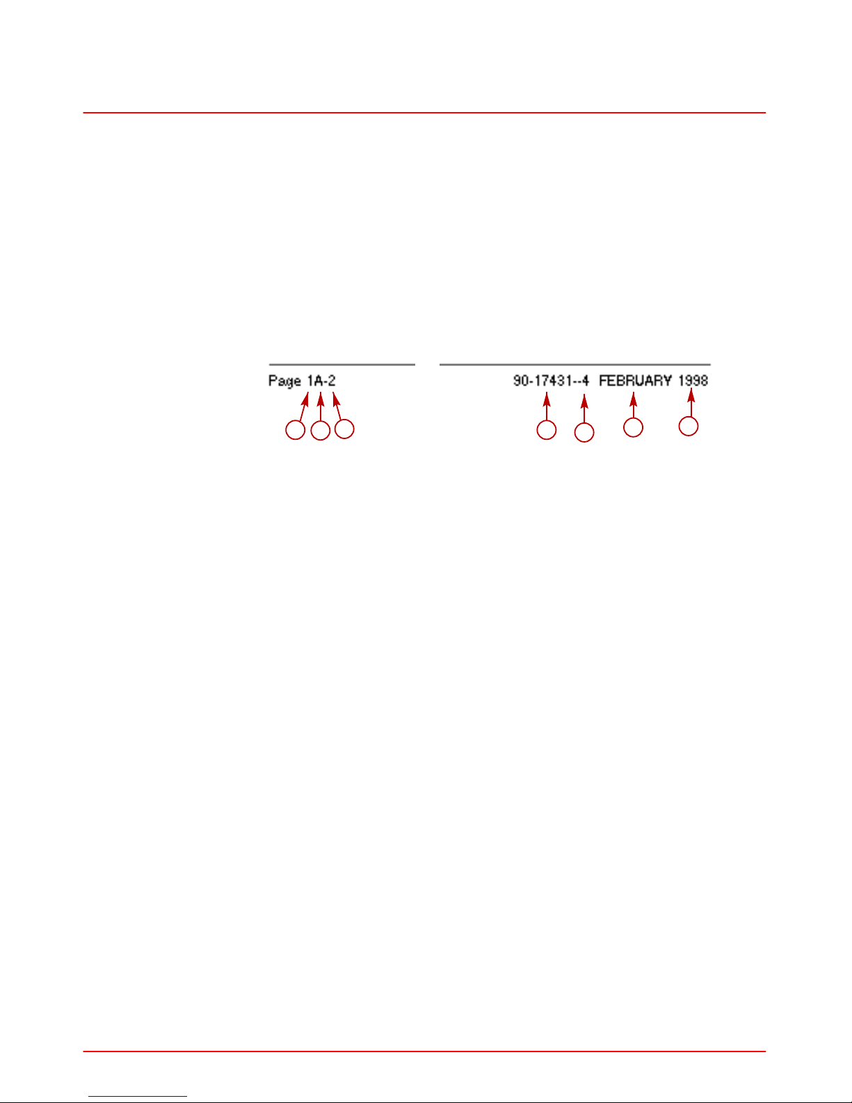
Page Numbering
Two number groups appear at the bottom of each page. Following is an example and
description.
a
b
c
d
e
f
g
a-Section Number
b-Section Part
c-Page Number
d-Manual Part Number
e-Revision Number
f-Month Printed
g-Year Printed
Page 15
GENERAL INFORMATION
SERVICE MANUAL NUMBER 28
90-863160 MAY 2000 Page 1A-3
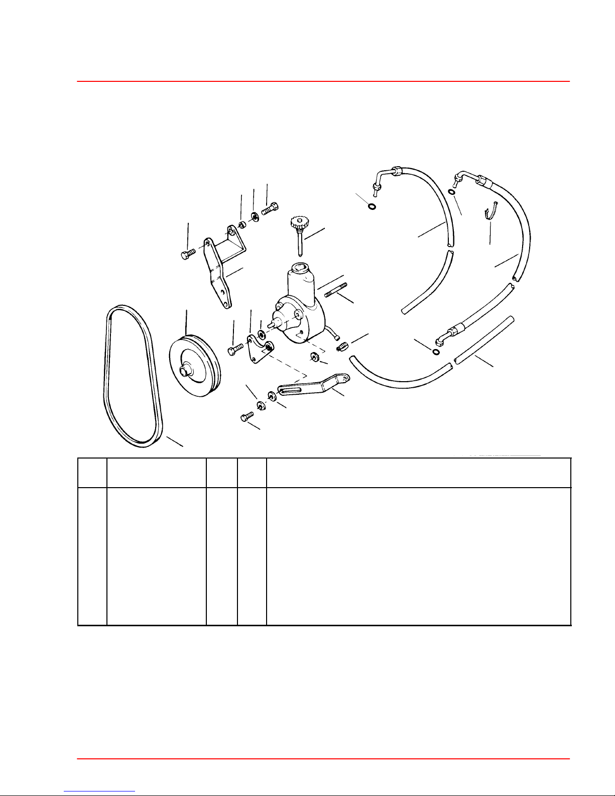
How to Read a Parts Manual
Power Steering Pump Assembly
1
2
3
4
5
6
7
8
9
10
REF.
NO.
PART NO. SYM. QTY. DESCRIPTION
1
90507A12 1 PUMP ASSEMBLY-Power Steering
2
36-95805 1 CAP
3
73873A1 1 PULLEY
4
16-41877 1 STUD
5
57-65607T 1 V-BELT
6
32-806684 1 HOSE-Pressure (FITTINGS ON BOTH ENDS)
7
25-89879 1 O-RING
8
25-806232 1 O-RING
9
13-35048 1 LOCKWASHER (3/8 in.)
10
61990 1 CABLE TIE
REF. NO. : Number shown next to part on exploded view
PART NO. : Mercury Part Number for ordering. If NSS (not sold separately) sometimes GM
part number will be given in description column.
QTY. : The quantity that must be ordered.
DESCRIPTION : Description of part, what parts are included with a part (all indented items
come with the main item above the indented parts), serial number information, and special
information.
Page 16
IMPORTANT INFORMATION SERVICE MANUAL NUMBER 28
Page 1A-4 90-863160 MAY 2000
Introduction
This comprehensive overhaul and repair manual is designed as a service guide for the
MerCruiser models previously listed. It provides specific information, including procedures
for disassembly, inspection, assembly and adjustment, to enable dealers and service
mechanics to repair these products.
Before attempting repairs, that procedure should first be read through to help understand
the methods and tools used and the cautions and warnings required for safety.
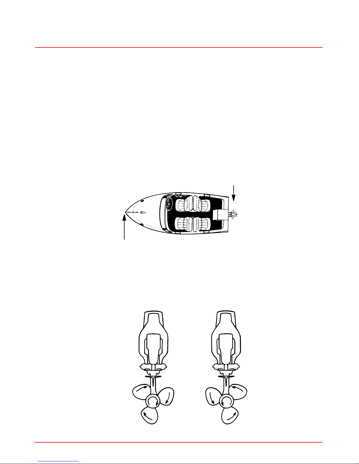
Directional References
Front of boat is bow; rear is stern. Starboard side is right side; port side is left side. In this
service manual, all directional references are given as they appear when viewing boat from
stern, looking toward bow.
72000
STARBOARD
(RIGHT)
PORT
(LEFT)
FORE or BOW
(FRONT)
AFT or STERN
(REAR)
Propeller Rotation
Propeller rotation for sterndrive can be right hand or left hand rotation as viewed from the
aft end of the propeller.
Right Hand Rotation Left Hand Rotation
Page 17
GENERAL INFORMATION
SERVICE MANUAL NUMBER 28
90-863160 MAY 2000 Page 1A-5
Sterndrive Unit 10-Hour Break-In Period (New or With
Replacement Gears)
1. Avoid full throttle starts.
2. DO NOT operate at any one constant speed for extended periods of time.
3. DO NOT exceed 75% of full throttle during the first 5 hours. During the next 5 hours,
operate at intermittent full throttle.
4. Drive unit should be shifted into forward gear a minimum of 10 times during break-in,
with run-in time at moderate rpm after each shift.
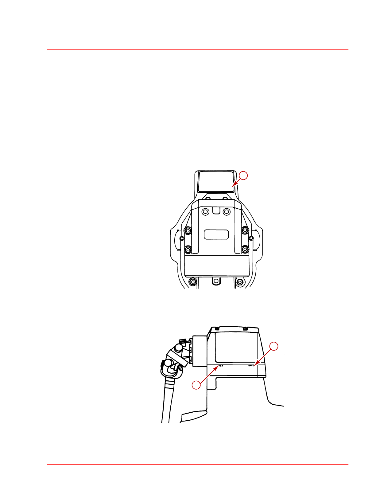
Serial Number Locations and Engine Designation Decal
a
Transom Assembly Serial Number Location
a-Transom Assembly Serial Number
b
a
Sterndrive Unit Serial Number Location - Port Side Decal
a-Sterndrive Unit Serial Number
b-Sterndrive Unit Gear Ratio
Page 18

IMPORTANT INFORMATION SERVICE MANUAL NUMBER 28
Page 1A-6 90-863160 MAY 2000
THIS PAGE IS INTENTIONALLY BLANK
Page 19

1
B
MAINTENANCE
SERVICE MANUAL NUMBER 28
90-863160 MAY 2000 Page 1B-1
IMPORTANT INFORMATION
Section 1B - Maintenance
Table of Contents
Lubricants / Sealants / Adhesives 1B-2. . . . .
Maintenance Schedules 1B-3. . . . . . . . . . . . .
Maintenance Intervals 1B-3. . . . . . . . . . . . .
Gas Sterndrive 1B-3. . . . . . . . . . . . . . . . . . . . . .
Routine Maintenance * 1B-3. . . . . . . . . . . .
Gas Sterndrive(Continued) 1B-4. . . . . . . . . . .
Scheduled Maintenance * 1B-4. . . . . . . . .
Specifications 1B-5. . . . . . . . . . . . . . . . . . . . . . .
Torque Specification 1B-5. . . . . . . . . . . . . . . . .
Fluid Capacities 1B-5. . . . . . . . . . . . . . . . . . . . .
Lubrication 1B-5. . . . . . . . . . . . . . . . . . . . . . . . .
Shift Cable Pivot Points 1B-5. . . . . . . . . . .
Propeller Shaft 1B-6. . . . . . . . . . . . . . . . . . .
Steering System 1B-6. . . . . . . . . . . . . . . . . .
Tie Bar Pivot Points 1B-7. . . . . . . . . . . . . . .
Transom Gimbal Housing Assembly Swivel
Shaft and Gimbal Bearing 1B-7. . . . . . . . .
Checking and Adding Sterndrive Oil 1B-8. . .
Inspection 1B-9. . . . . . . . . . . . . . . . . . . . . . .
Changing Sterndrive Oil 1B-10. . . . . . . . . . . . . .
General Maintenance 1B-12. . . . . . . . . . . . . . . .
Maintaining Power Package Exterior Sur-
faces 1B-12. . . . . . . . . . . . . . . . . . . . . . . . . . . .
Steering Head and Remote Control Mainte-
nance 1B-12. . . . . . . . . . . . . . . . . . . . . . . . . . .
Checking Quicksilver MerCathode System . .
1B-12
Maintaining Anodic Plate 1B-12. . . . . . . . . .
Boat Bottom Care 1B-12. . . . . . . . . . . . . . . .
Anti-fouling Paint 1B-12. . . . . . . . . . . . . . . . .
Maintaining Ground Circuit Continuity 1B-13
Power Package Layup 1B-13. . . . . . . . . . . . . . .
Engine 1B-13. . . . . . . . . . . . . . . . . . . . . . . . . .
Sterndrive 1B-13. . . . . . . . . . . . . . . . . . . . . . .
Power Package Recommissioning 1B-14. . . .
Engine 1B-14. . . . . . . . . . . . . . . . . . . . . . . . . .
Sterndrive 1B-14. . . . . . . . . . . . . . . . . . . . . . .
Page 20

MAINTENANCE SERVICE MANUAL NUMBER 28
Page 1B-2 90-863160 MAY 2000
Lubricants / Sealants / Adhesives
Description Part Number
Quicksilver 4-Cycle 25W-40 Marine Engine Oil 92-802837A1
SAE 20W, 30W Or 40W Engine Oil Obtain Locally
Quicksilver High Performance Gear Lube 92-802854A1
Extended Life Ethylene Glycol Antifreeze Obtain Locally
Quicksilver Special Lubricant 101 92-13872A1
Quicksilver Engine Coupler Spline Grease 92-802869A1
Quicksilver Corrosion Guard Spray 92-802878 55
Quicksilver 2-4-C Marine Lubricant With Teflon 92-825407A3
Quicksilver U-Joint and Gimbal Bearing Grease 92-828052A2
Quicksilver Power Trim And Steering Fluid 92-802880A1
Exxon Unirex EP 2 Grease Obtain Locally
Quicksilver Hydraulic Fluid 64-826485A1
Texaco H015 92-862014A1
SeaStar Hydraulic Fluid HA5430
Approved Hydraulic
Chevron Aviation Fluid A
Steering Fluids
Mobil Aero HFA
Obtain Locally
Shell Aero 4
Fluid meeting MIL Specification H5606C
Page 21
MAINTENANCE
SERVICE MANUAL NUMBER 28
90-863160 MAY 2000 Page 1B-3
Maintenance Schedules
Maintenance Intervals
Maintenance intervals and tasks, as shown in this schedule, or as found in previously
printed schedules, are based on an average boating application and environment.
However, individual operating habits and personal maintenance preferences can have an
impact on the suggested intervals. In consideration of these factors, Mercury MerCruiser
has adjusted some maintenance intervals and corresponding tasks to be performed. In
some cases, this may allow for more tasks to be performed in a single visit to the servicing
dealer, rather than multiple visits. Therefore, the boat owner and servicing dealer must
discuss the current Maintenance Schedule and develop appropriate maintenance intervals
to coincide with the individual operating habits, environment and maintenance
requirements.
CAUTION
Always disconnect battery cables from battery BEFORE working around electrical
systems components to prevent injury to yourself and damage to electrical system
should a wire be accidentally shorted.
Gas Sterndrive
Routine Maintenance *
Each
Day
Start
Each
Day
End
Weekly
Every
Two
Months
Check crankcase oil (interval can be extended based on experience).
If operating in salt, brackish or polluted waters, flush cooling system after each use.
Check sterndrive unit oil level, trim pump oil level and steering fluid
level.
Check water pickups for debris or marine growth. Check water
strainer and clean. Check coolant level.
Inspect sterndrive unit anodes and replace if 50 percent eroded.
Inspect fuel pump sight tube (if equipped) and have pump replaced
if fuel is present.
Check battery connections and fluid level.
Lubricate propeller shaft and the retorque nut (if operating in only
freshwater, this maintenance may be extended to every four
months).
Operating in saltwater only: treat engine surface with corrosion
guard.
* Only perform maintenance that applies to your particular power package
Standard Models
Horizon Models
Page 22

MAINTENANCE SERVICE MANUAL NUMBER 28
Page 1B-4 90-863160 MAY 2000
Gas Sterndrive(Continued)
Scheduled Maintenance *
Annu-
ally
Every
100
hours or
Annually
Every
200
hours
or 3
years
Every
300
hours
or 3
years
Every
2
years
Every
5
years
Touch-up power package paint and spray with Corrosion Guard.
Change crankcase oil and filter.
Change sterndrive unit oil and retorque connection of
gimbal ring to steering shaft.
Replace fuel filter(s).
Check steering system and remote control for loose,
missing or damaged parts. Lubricate cables and linkages.
Inspect U-joints, splines and bellows. Check clamps.
Check engine alignment. Lubricate U-joints splines.
Lubricate gimbal bearing and engine coupler.
Check continuity circuit for loose or damaged connec-
tions. Test MerCathode unit output on Bravo Models.
Retorque engine mounts.
Check spark plugs, wires, distributor cap and ignition
timing. Check and adjust idle speed.
Clean flame arrestor and crankcase ventilation hoses.
Replace PCV valve.
Check electrical system for loose, damaged or corroded
fasteners.
Inspect condition and tension of belts.
Check cooling system and exhaust system hose clamps
for tightness. Inspect both systems for damage or leaks.
Disassemble and inspect seawater pump and replace
worn components.
Clean seawater section of closed cooling system.
Clean, inspect and test pressure cap.
Replace coolant.
* Only perform maintenance that applies to your particular power package
Standard Models
Horizon Models
Whichever Occurs First
Interval will be reduced if not using extended life coolant.
Lubricate engine coupler every 50 hours if operated at idle for prolonged periods of time.
Page 23
MAINTENANCE
SERVICE MANUAL NUMBER 28
90-863160 MAY 2000 Page 1B-5
Specifications
Torque Specification
Fastener Location lb-in. lb-ft Nm
Sterndrive Unit Fill/Drain Plug 40 4.5
Sterndrive Unit Vent Plug 40 4.5
We recommend the use of Quicksilver Maintenance Products where specified.
Fluid Capacities
NOTICE
Unit Of Measurement: U.S. Quarts (Liters)
All capacities are approximate fluid measures.
Model Bravo One Bravo Two Bravo Three
Sterndrive Unit Oil Capacity 88 (2603) 104 (3076) 96 (2839)
Lubrication
Shift Cable Pivot Points
22245
a
a-Pivot Points
Page 24

MAINTENANCE SERVICE MANUAL NUMBER 28
Page 1B-6 90-863160 MAY 2000
Propeller Shaft
77047
72239
a
a
a
77046
76910
Bravo One / Bravo Two Sterndrives Bravo Three Sterndrive/ Bravo XZ & XR
a-Propeller Shaft
Steering System
WARNING
Transom end of steering cable MUST BE fully retracted into cable housing when
lubricating cable. If cable is lubricated while extended, hydraulic lock of cable could
occur.
71901
b
76860
a
b
c
c
Control Valve
a-Steering Cable End
b-Pivot Point
c-Pivot Bolts
d-Adjusting Slots
Page 25
MAINTENANCE
SERVICE MANUAL NUMBER 28
90-863160 MAY 2000 Page 1B-7
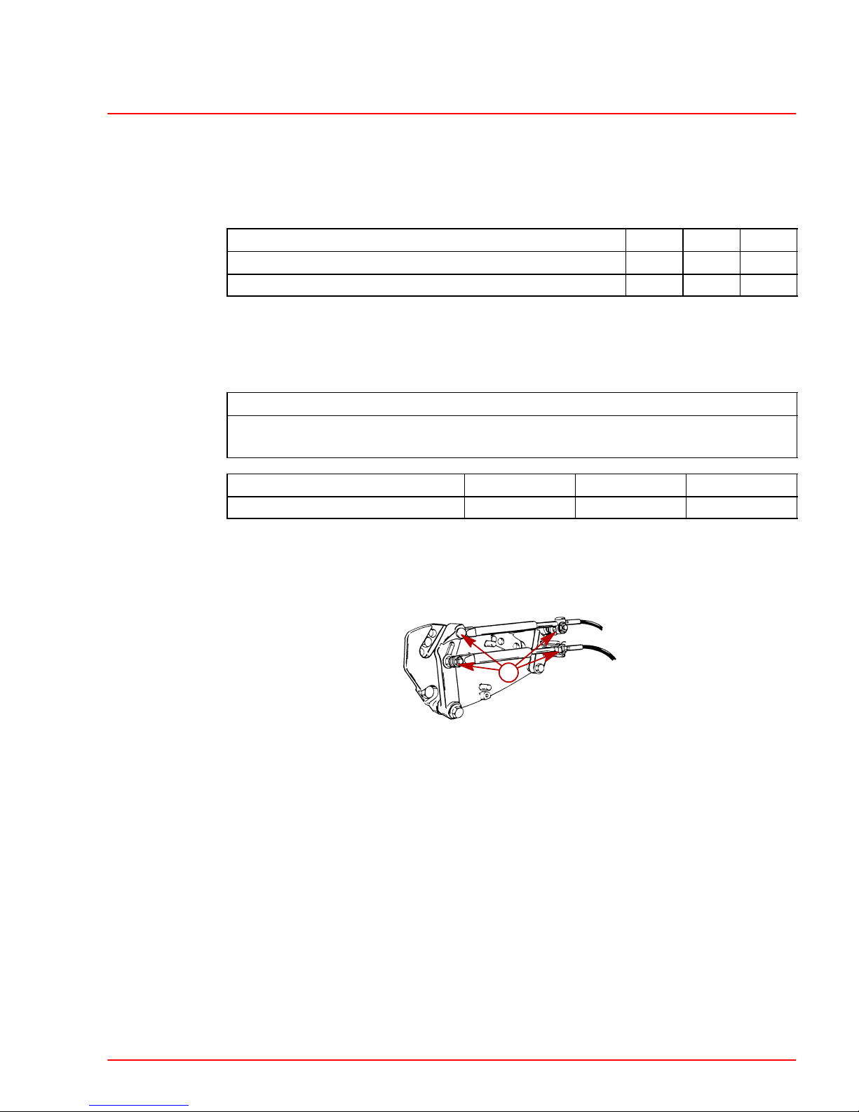
Tie Bar Pivot Points
MODELS WITH CONTROL VALVE MOUNTED ON STARBOARD TRANSOM ASSEMBLY
22079
22079
a
a
Starboard Engine Port Engine
a-Pivot Point
MODELS WITH CONTROL VALVE MOUNTED ON PORT TRANSOM ASSEMBLY
22079
22079
a
a
Starboard Engine Port Engine
a-Pivot Point
Transom Gimbal Housing Assembly Swivel Shaft and Gimbal Bearing
50072
b
a-Gimbal Bearing Grease Fitting
Page 26
MAINTENANCE SERVICE MANUAL NUMBER 28
Page 1B-8 90-863160 MAY 2000
Checking and Adding Sterndrive Oil
IMPORTANT: Position sterndrive unit in DOWN/IN position so that anti-ventilation
plate is level.
CAUTION
If more than 2 fl. oz. (59 ml) of oil is required to fill sterndrive unit, an oil leak may
exist. Find and correct cause of leak before unit is placed in operation.
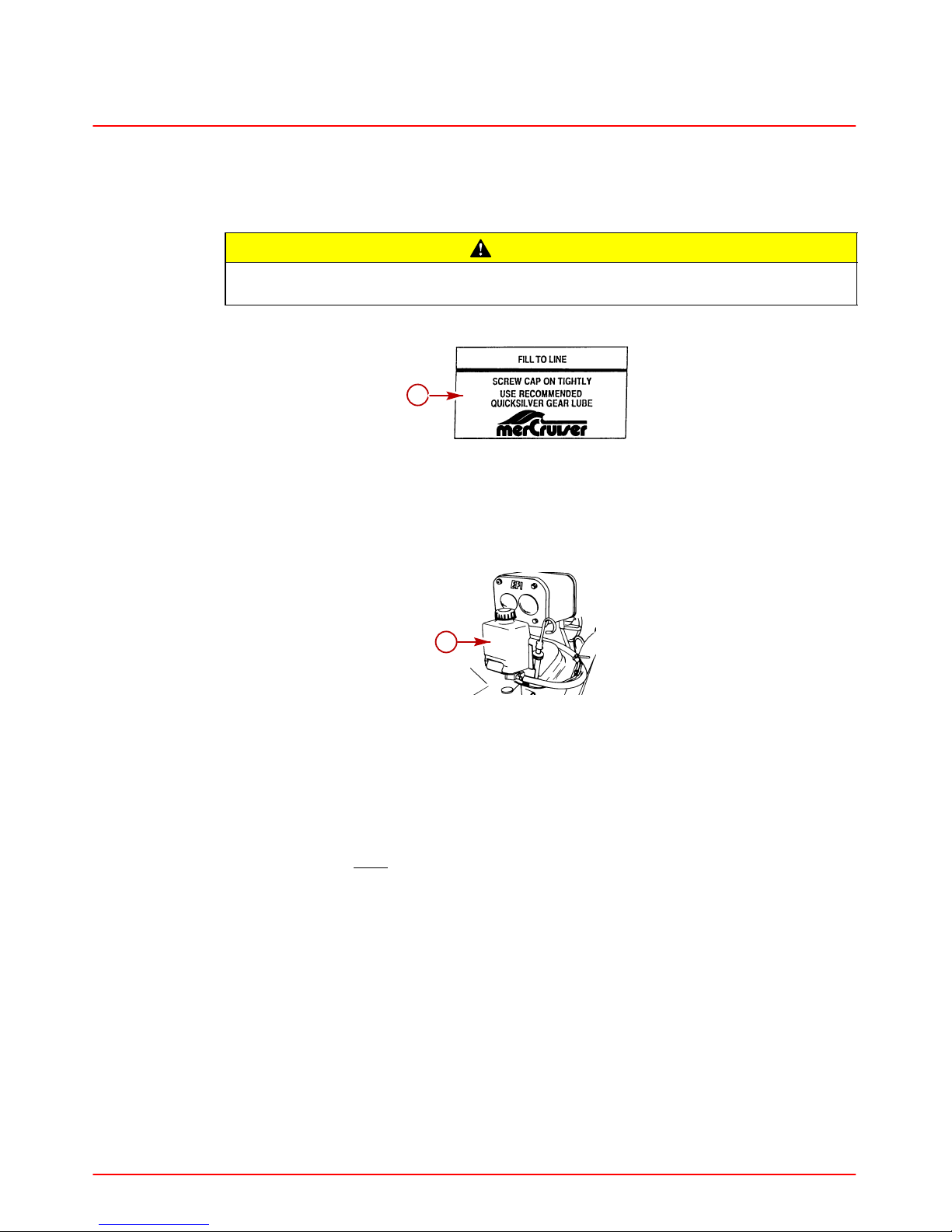
NOTE: Sterndrive unit oil level is checked at gear lube monitor.
50323
a
a-Gear Lube Monitor Decal
IMPORTANT: Oil level in gear lube monitor will rise and fall during sterndrive
operation; always check oil level when sterndrive is cool and engine is shut down.
NOTE: Drive oil will purge from gear lube monitor if rubber seal is not in cap.
71990
a
a-Gear Lube Monitor
1. Fill gear lube monitor to FULL line on decal.
2. Ensure rubber seal is in place on square gear lube monitor cap.
3. Install gear lube monitor cap. Tighten cap 1/4 turn after cap contacts seal.
IMPORTANT: Do NOT overtighten cap.
4. Check oil level in gear lube monitor.
Page 27
MAINTENANCE
SERVICE MANUAL NUMBER 28
90-863160 MAY 2000 Page 1B-9
Inspection
Periodically inspect lubricant for water to ensure that sterndrive unit seals are not leaking.
Check for water at bottom of gear lube monitor. If a water leak is indicated the sterndrive
unit must be resealed.
CAUTION
If more than 2 fl. oz. (59ml) of Quicksilver High Performance Gear Lube is required
to fill gear lube monitor, a seal may be leaking. Find and correct cause of leak before
unit is placed in operation.
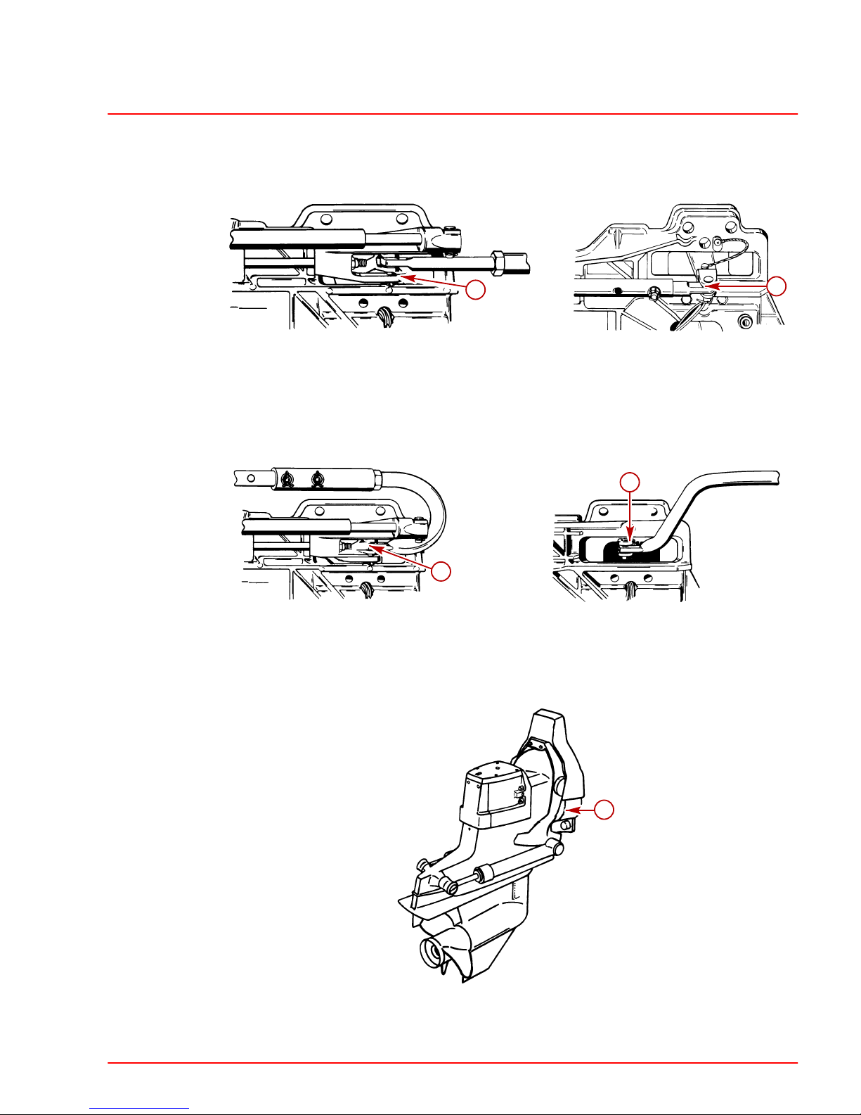
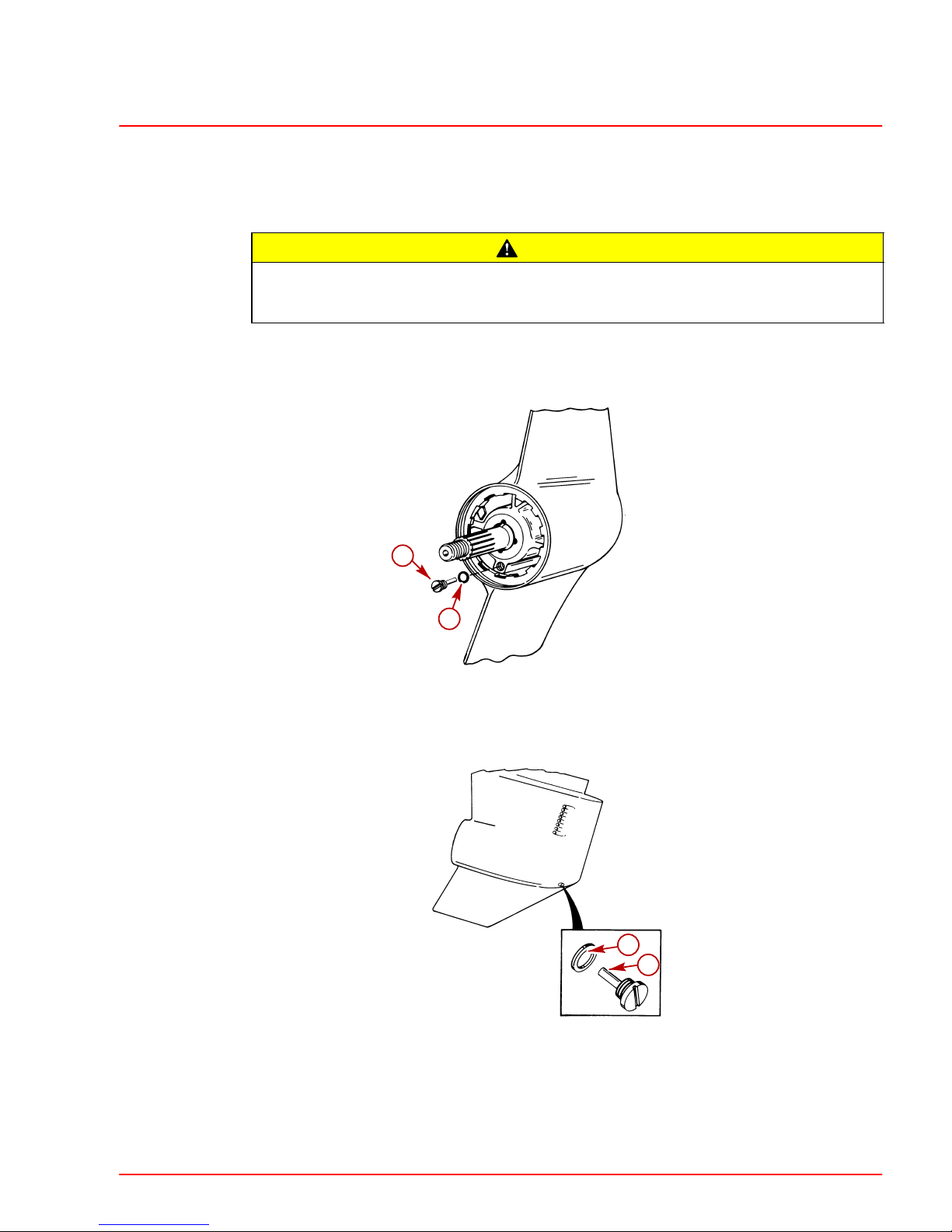
IMPORTANT: If sterndrive unit has set overnight or longer, check for water in sterndrive unit, as follows:
1. Bravo I: Trim sterndrive unit to full DOWN/IN position.
70023
a
b
a-Oil Fill/Drain Plug
b-Sealing Washer
2. Bravo II and III: Trim sterndrive unit to full UP/OUT position.
22101
22103
a
b
a-Oil Fill/Drain Plug
b-Sealing Washer
3. Remove fill/drain plug to sample lubricant. If water runs out sterndrive unit is leaking and
must be resealed.
4. Reinstall fill/drain plug. Torque to 40 lb-in. (4.5 Nm).
Page 28
MAINTENANCE SERVICE MANUAL NUMBER 28
Page 1B-10 90-863160 MAY 2000
Changing Sterndrive Oil
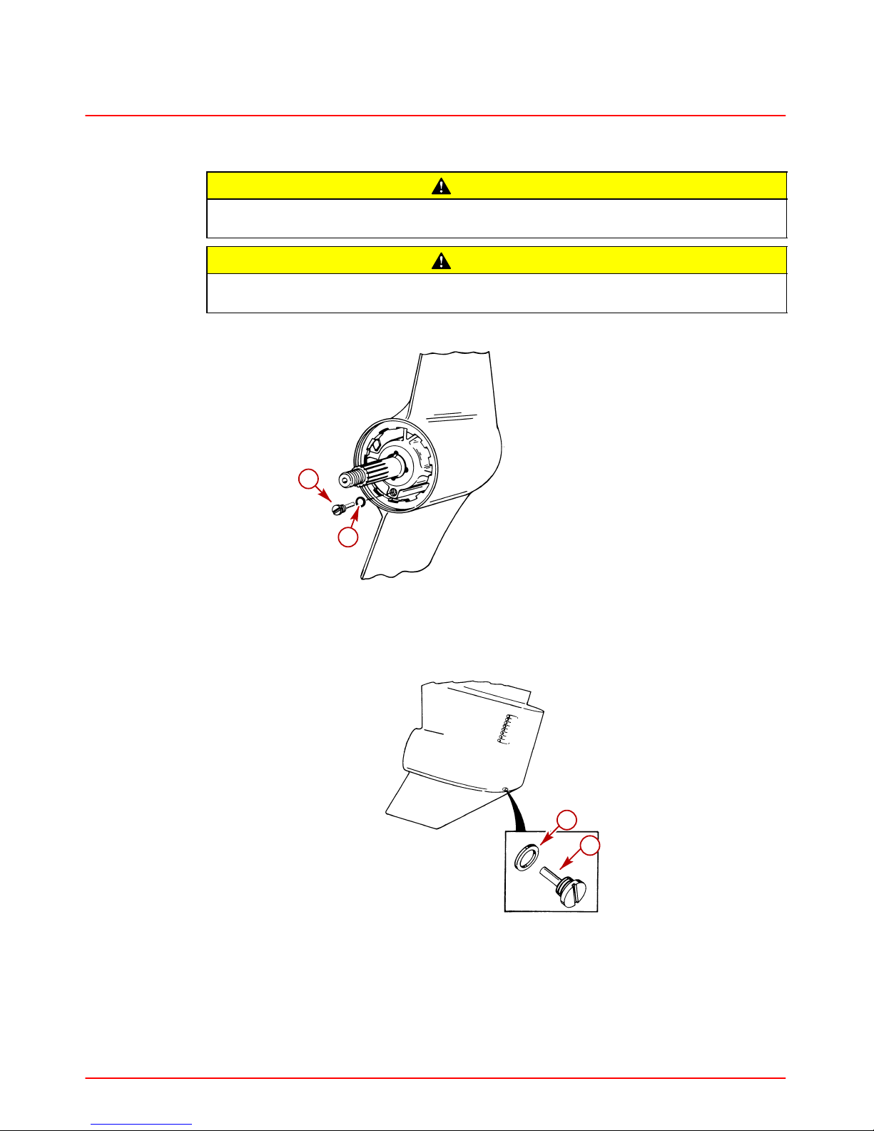
CAUTION
If any water drains from fill/drain hole a leak in sterndrive unit may exist. Find and
correct cause of leak before placing unit back in operatIon.
CAUTION
DO NOT attempt to fill sterndrive unit through oil vent holes, as air will be trapped
in sterndrive unit and unit will be damaged from lack of lubrication.
1. Bravo I: Trim sterndrive unit to full DOWN/IN position.
70023
a
b
a-Oil Fill/Drain Plug
b-Sealing Washer
2. Bravo II and III: Trim sterndrive unit to full UP/OUT position.
22101
22103
a
b
a-Oil Fill/Drain Plug
b-Sealing Washer
3. Remove sterndrive unit gear lube monitor from bracket.
4. Remove cap, empty contents of gear lube monitor into suitable container and discard.
5. Clean gear lube monitor thoroughly.
6. Return gear lube monitor to bracket. Do not refill at this time.
Page 29
MAINTENANCE
SERVICE MANUAL NUMBER 28
90-863160 MAY 2000 Page 1B-11
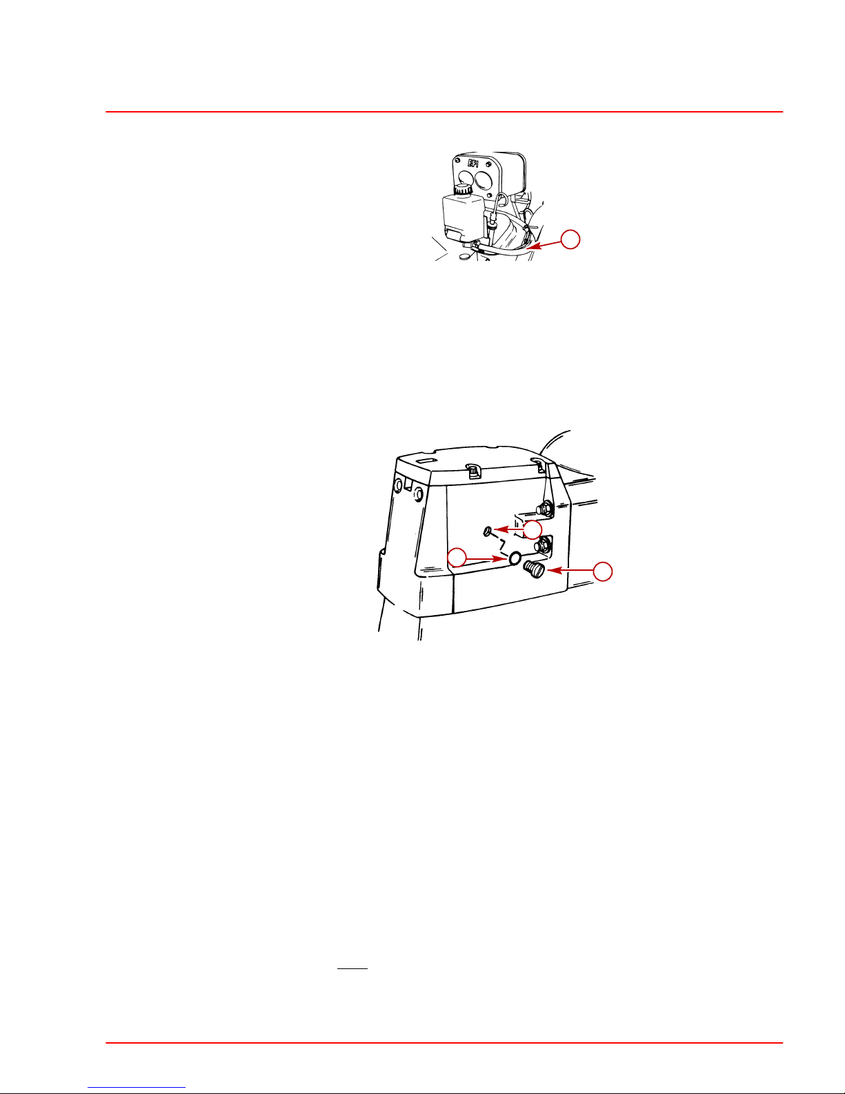
7. Check condition of hose and hose connections. Replace as necessary.
71990
a
a-Gear Lube Monitor
8. Remove sterndrive unit vent plug and fill/drain plug. Allow lubricant to drain completely.
9. If sterndrive unit is draining in full DOWN/IN position, trim to full UP/OUT position after
draining drain any remaining oil from internal driveshaft housing ledges.
10. Trim sterndrive unit to full DOWN/IN position (with anti-ventilation plate level) to
complete draining process.
c
a
b
a-Oil Vent Plug
b-Sealing Washer
c-Vent Hole
11. Using lubricant pump, fill sterndrive unit through fill/drain hole with lubricant until oil is
even with bottom edge of vent hole.
12. Without removing lubricant pump fitting from fill/drain hole, reinstall oil vent plug and
sealing washer. Torque to 40 lb-in. (4.5 Nm).
13. Continue filling drive until there is one inch of oil in the gear lube monitor.
14. Remove lubricant pump fitting and quickly reinstall fill/drain plug and sealing washer.
Torque to 40 lb-in. (4.5 Nm).
NOTE: Drive oil will purge from square gear lube monitor if rubber seal is not in cap.
15. Fill gear lube monitor to FULL line on decal.
16. Ensure rubber seal is in place on gear lube monitor cap.
17. Install gear lube monitor cap.
IMPORTANT: Do NOT
overtighten cap.
18. Check oil level in gear lube monitor.
19. Recheck oil level after first use.
Page 30

MAINTENANCE SERVICE MANUAL NUMBER 28
Page 1B-12 90-863160 MAY 2000
General Maintenance
Maintaining Power Package Exterior Surfaces
Entire power package should be sprayed at recommended intervals with Quicksilver
Corrosion Guard. Follow instructions on can for proper application.
Entire power package should be cleaned and external surfaces that have become bare
should be repainted with Quicksilver Primer and Spray Paint at recommended intervals.
Steering Head and Remote Control Maintenance
Lubricate steering head and remote control with 2-4-C Marine Lubricant with T eflon. Inspect
steering head and remote control for ease of operation.
Checking Quicksilver MerCathode System
If boat is equipped with a Quicksilver MerCathode System, system should be tested to
ensure that it is providing adequate output to protect underwater metal parts on boat. Test
should be made where boat is moored, using Quicksilver Reference Electrode and Test
Meter. Refer to SECTION 7.
Maintaining Anodic Plate
Each sterndrive unit is equipped with a sacrificial anodic plate to help protect underwater
metal parts from galvanic corrosion. Because of its self-sacrificing nature, anodic plate
MUST BE replaced if eroded 50% or more. Refer to SECTION 7.
Boat Bottom Care
To achieve maximum performance and fuel economy, boat bottom MUST BE kept clean.
Accumulation of marine growth or other foreign matter can greatly reduce boat speed and
increase fuel consumption. To ensure best performance and efficiency, periodically clean
boat bottom in accordance with manufacturer ’s recommendations.
In some areas, it may be advisable to paint the bottom to help prevent marine growth. Refer
to the following information for special notes about the use of anti-fouling paints.
Anti-fouling Paint
IMPORTANT: Corrosion damage that results from the improper application of antifouling paint will not be covered by the limited warranty.
Painting Boat Hull or Boat Transom: Anti-fouling paint may be applied to boat hull and
boat transom but you must observe the following precautions:
IMPORTANT: DO NOT paint anodes or MerCathode System reference electrode and
anode, as this will render them ineffective as galvanic corrosion inhibitors.
Page 31

MAINTENANCE
SERVICE MANUAL NUMBER 28
90-863160 MAY 2000 Page 1B-13
IMPORTANT: If anti-fouling protection is required for boat hull or boat transom, copper or tin base paints, if not prohibited by law, can be used. If using copper or tin
based anti-fouling paints, observe the following:
• Avoid an electrical interconnection between the Mercury MerCruiser Product,
Anodic Blocks, or MerCathode System and the paint by allowing a minimum of
1-1/2 in. (40 mm) UNPAINTED area on transom of the boat around these items.
71176
a
b
a-Painted Boat Transom
b-Minimum 1-1/2 in (40 mm) UNPAINTED Area Around Transom Assembly
NOTE: Sterndrive unit and transom assembly can be painted with a good quality marine
paint or an anti-fouling paint that DOES NOT
contain copper, tin, or any other material that
could conduct electrical current. Do not paint drain holes, anodes, MerCathode system and
items specified by boat manufacturer.
Maintaining Ground Circuit Continuity
The transom assembly and sterndrive unit are equipped with a ground wire circuit to ensure
good electrical continuity between engine, transom assembly and sterndrive components.
Good continuity is essential for the MerCathode System to function effectively. Refer to
SECTION 7.
Power Package Layup
Engine
Refer to appropriate Engine Service Manual.
Sterndrive
1. Lubricate steering system. Refer to SECTION 6.
2. Lubricate transom gimbal bearing and propeller shaft. Refer to SECTION 4 and
SECTION 1B.
3. Lubricate sterndrive unit U-joint shaft splines and cross bearings. Refer to SECTION 3A.
4. Inspect U-joint bellows for cracks or other signs of deterioration. Check bellows clamps
for tightness. Refer to SECTION 4.
5. Check engine alignment. Refer to Engine Service Manual.
6. Change sterndrive unit oil. Refer to SECTION 1B.
7. Inspect sterndrive for damage. Repair or replace damaged components.
8. Clean sterndrive exterior surfaces and repaint any bare metal surfaces with Quicksilver
Primer and Spray Paint. Refer to SECTION 1B.
Page 32

MAINTENANCE SERVICE MANUAL NUMBER 28
Page 1B-14 90-863160 MAY 2000
9. After paint has dried, spray entire sterndrive with Quicksi l ver Corrosion G uar d. R efer to
SECTION 1B.
CAUTION
Store sterndrive unit in the full trim DOWN/IN position. U-joint bellows may develop
a “set” if unit is stored in raised position and may fail when unit is returned to service.
10. If not already done, place sterndrive unit in the full trim DOWN/IN position.
11. Store battery. Refer to battery manufacturer’s instructions.
Power Package Recommissioning
Engine
Refer to appropriate Engine Service Manual.
Sterndrive
1. Perform ALL maintenance specified for completion “Annually” in “Maintenance Chart”
except items which were performed at the time of sterndrive layup.
2. Install fully-charged battery.
3. Clean battery cable clamps and terminals.
4. Reconnect battery cables. Be sure to tighten clamps securely.
5. Apply a thin coat of petroleum based grease to clamps and terminals to help retard
corrosion.
6. After recommissioning and starting engine, check steering system and shift control for
proper operation.
Page 33

1
C
TROUBLESHOOTING
SERVICE MANUAL NUMBER 28
90-863160 MAY 2000 Page 1C-1
IMPORTANT INFORMATION
Section 1C - Troubleshooting
Table of Contents
Table of Contents 1C-1. . . . . . . . . . . . . . . . . . . . .
Troubleshooting 1C-2. . . . . . . . . . . . . . . . . . . . . . .
Sterndrive Unit Troubleshooting 1C-2. . . . . . . . .
Sterndrive Unit Will Not Slide Into
Bell Housing 1C-2. . . . . . . . . . . . . . . . . . . . . . .
Drive Unit Does Not Shift Into Gear;
Remote Control Shift Handle Moves 1C-2. .
Drive Unit Does Not Shift Into Gear;
Remote Control Shift Handle Does
Not Move 1C-3. . . . . . . . . . . . . . . . . . . . . . . . .
Drive Unit Shifts Hard 1C-3. . . . . . . . . . . . . . .
Drive Unit In Gear, Will Not Shift
Out Of Gear 1C-3. . . . . . . . . . . . . . . . . . . . . . .
Gear Housing Noise 1C-4. . . . . . . . . . . . . . . .
Drive Shaft Housing Noise 1C-4. . . . . . . . . . .
Drive Shaft Housing Noise
(Continued) 1C-5. . . . . . . . . . . . . . . . . . . . . . .
Drive Shaft Housing Noise
(Continued) 1C-6. . . . . . . . . . . . . . . . . . . . . . .
Power Shift 1C-7. . . . . . . . . . . . . . . . . . . . . . . . . . .
System Does Not React 1C-7. . . . . . . . . . . . .
System Binds 1C-7. . . . . . . . . . . . . . . . . . . . . .
Performance Troubleshooting 1C-8. . . . . . . . . . .
Low WOT Engine RPM 1C-8. . . . . . . . . . . . . .
High WOT Engine RPM 1C-8. . . . . . . . . . . . .
Propeller Ventilating/Cavitating 1C-8. . . . . . .
Poor Boat Performance And/Or Poor
Maneuverability-Bow Too Low 1C-9. . . . . . .
Poor Boat Performance And/Or Poor
Maneuverability-Bow Too High 1C-9. . . . . . .
Power Steering 1C-10. . . . . . . . . . . . . . . . . . . . . .
Hard Steering - Helm And Cable 1C-10. . . . .
Hard Steering (Engine Running)
- Power Steering System 1C-10. . . . . . . . . . .
Power Steering System External
Fluid Leaks 1C-10. . . . . . . . . . . . . . . . . . . . . . .
Compact Hydraulic Steering 1C-11. . . . . . . . . . .
Important Information 1C-11. . . . . . . . . . . . . .
Helm Beco me s Ja mme d Du rin g Fillin g 1C-11
System Difficult To Fill 1C-11. . . . . . . . . . . . . .
Steering Hard To Turn 1C-11. . . . . . . . . . . . . .
Helm Unit Bumpy
- Requires Too Many Turns 1C-11. . . . . . . . .
Power Trim Electrical System 1C-12. . . . . . . . . .
Power Trim System Wiring Diagram 1C-16. . . .
Power Trim Hydraulic System 1C-17. . . . . . . . . .
Power Trim Hydraulic Schematic 1C-21. . . . . . .
Auto Trim II Electrical System 1C-22. . . . . . . . . .
Auto Trim II System Wiring Diagram 1C-28. . . .
Corrosion Protection 1C-29. . . . . . . . . . . . . . . . . .
Page 34

TROUBLESHOOTING SERVICE MANUAL NUMBER 28
Page 1C-2 90-863160 MAY 2000
Troubleshooting
This section is a guide for performance and product troubleshooting. Referrals to specific
sections of this manual are made where special tests or repair procedure are to be
performed.
Because of the relationship between Power Package components (engine and sterndrive),
it will be necessary in some cases to simultaneously refer to the appropriate Engine Service
Manual for further troubleshooting information.
Effective troubleshooting is best enhanced by:
• Personal product knowledge and experience of the trained mechanic/technician.
• Allowing adequate time for testing and analysis.
• Utilizing these charts as a “guide” - a starting point.
Sterndrive Unit Troubleshooting
Sterndrive Unit Will Not Slide Into Bell Housing
Cause Special Instructions
U-joint shaft splines not aligned with
engine coupler splines.
Rotate propeller shaft
COUNTERCLOCKWISE to align
splines.
Engine not aligned. Check engine alignment.
Gimbal bearing not properly installed.
Check engine alignment to determine
if gimbal bearing is cocked or
improperly installed in gimbal housing.
Damaged U-joint shaft splines and/or
engine coupler splines.
Inspect and replace if necessary.
Drive Unit Does Not Shift Into Gear; Remote Control Shift Handle Moves
NOTE:For additional information on troubleshooting, refer to SECTION 2A and see
“Troubleshooting Shift Problems.”
Cause Special Instructions
Shift cables improperly adjusted. Adjust shift cables.
Shift cables not connected. Install and adjust shift cables.
Inner core wire broken or loose. Reconnect or replace inner core wire.
Page 35

TROUBLESHOOTING
SERVICE MANUAL NUMBER 28
90-863160 MAY 2000 Page 1C-3
Drive Unit Does Not Shift Into Gear; Remote Control Shift Handle Does Not
Move
NOTE:For additional information on troubleshooting, refer to SECTION 2A and see
“Troubleshooting Shift Problems.”
Cause Special Instructions
Control box not properly assembled. Properly reassemble control box.
Broken or damaged linkage in control
box.
Repair linkage.
Controls improperly adjusted-cable
end guide hitting brass barrel.
Adjust shift cables.
Drive Unit Shifts Hard
NOTE:For additional information on troubleshooting, refer to SECTION 2A and see
“Troubleshooting Shift Problems.”
Cause
Special Instructions
Shift cables improperly adjusted. Adjust shift cables.
Damaged remote control or drive unit
shift cable.
Replace cable(s) and adjust.
Shift cable too short (sharp bends) or
too long (loops and long bends).
Select and install proper length cable.
Corroded shift cables.
Replace, adjust and check for water
leakage.
Internal wear in remote control box. Repair as needed.
Shift cable attaching nuts too tight (end
cannot pivot).
Properly install nuts.
Shift cable pivot ends are corroded or
not lubricated.
Clean and lubricate.
Drive Unit In Gear, Will Not Shift Out Of Gear
NOTE:For additional information on troubleshooting, refer to SECTION 2A and see
“Troubleshooting Shift Problems.”
Cause Special Instructions
Shift cable broken. Replace cable and adjust.
Cable end not connected in drive unit. Remove and reinstall drive unit.
Remote control damaged. Repair or replace remote control.
Internal shift mechanism damage. Repair or replace as necessary.
Page 36

TROUBLESHOOTING SERVICE MANUAL NUMBER 28
Page 1C-4 90-863160 MAY 2000
Gear Housing Noise
Cause Special Instructions
Metal particles in drive unit lubricant.
Disassemble, clean and inspect and
replace necessary components. (Refer
to SECTION 3B, 3C or 3D)
Propeller incorrectly installed.
Inspect mounting hardware. Install
propeller correctly.
Propeller shaft bent.
Inspect and replace if necessary.
(Refer to SECTION 3B, 3C or 3D)
Incorrect gear shimming.
Check gear housing backlash and
pinion gear height. (Refer to SECTION 3B,
3C or 3D)
Worn or damaged gears and/or
bearings caused by impact,
overheating or improper shimming.
Disassemble, inspect and replace. (Refer
to SECTION 3B, 3C or 3D)
Drive Shaft Housing Noise
Cause Special Instructions
Engine flywheel housing contacting
inner transom plate or exhaust pipe.
Determine cause for interference
(loose engine mounts, transom too
thin, etc.) and correct as necessary.
Propeller with untrue or out-of-balance
blades.
Repair or replace, as required.
Abnormal sterndrive operation.
Instruct operator on proper operating
technique.
U-joint cross and bearing assembly
retaining rings improperly installed or
of incorrect size.
Make sure that proper thickness
retaining rings are used and that rings
are fully seated in u-joint bearing cap
grooves. (Refer to SECTION 3A)
Excessive side-to-side play in U-joint
cross and bearing assemblies.
Replace cross and bearing assembly.
U-joint bearing caps contacting U-joint
bellows retention sleeve.
Make sure proper cross and bearing
assemblies are used. If interference is
severe, replace cross and bearing
assembly and / or sleeve assembly.
U-joint cross and bearings rough.
Replace assemblies. Signs of scoring,
galling or roughness are the result of lack
of lubricant. (Refer to SECTION 3A)
O-rings missing or flattened out on
U-joint shaft causing shaft to rattle
against ID of gimbal bearing.
Install new o-rings. (Refer to SECTION
3A)
Page 37

TROUBLESHOOTING
SERVICE MANUAL NUMBER 28
90-863160 MAY 2000 Page 1C-5
Drive Shaft Housing Noise (Continued)
Cause Special Instructions
Worn U-joint shaft splines and/or
engine coupler splines.
Remove U-joint coupling end yoke and
insert into gimbal bearing and engine
coupling. Rotate shaft back and forth.
If play is excessive, replace U-joint
coupling end yoke and/or engine
coupler, as necessary.
Engine alignment incorrect or engine
coupler crooked.
Adjust alignment. Ensure that
alignment tool moves in and out of
coupler freely. After proper alignment
has been obtained, check for a crooked
coupler by rotating engine coupler 1/2 turn
and rechecking alignment. If
proper alignment is no longer
observed, coupler is crooked and must
be replaced. (Refer to SECTION 2)
Gimbal bearing rough.
Replace gimbal bearing. (Refer to
SECTION 4)
IMPORTANT: Gimbal bearing and carrier
MUST BE replaced as an assembly be-
cause they are a matched set. Failure to
do this may result in a loose bearing fit in
carrier.
Loose gimbal bearing.
Reinstall bearing assembly using a new
tolerance ring if carrier is loose in
gimbal housing. If bearing is loose in
carrier, bearing assembly must be
replaced. (Refer to SECTION 4)
Gimbal bearing not fully seated in
gimbal housing.
Drive bearing assembly into place.
Excessive clearance between gimbal
ring and gimbal housing. This could
cause misalignment between bell
housing and gimbal housing and also
may allow gimbal ring to vibrate up
and down.
Check and adjust clearance. (Refer to
SECTION 4)
Improperly installed or failed rear
engine mounts. This will affect engine
alignment, but usually is not detectable
with engine alignment tool.
Check for uneven mount height, or
loose or soft mounts. Make sure there
is clearance between flywheel housing
and fiber washer. If no clearance exists,
mounts have probably sagged. Install
mounts correctly or replace, as
necessary.
Page 38

TROUBLESHOOTING SERVICE MANUAL NUMBER 28
Page 1C-6 90-863160 MAY 2000
Drive Shaft Housing Noise (Continued)
Cause Special Instructions
Boat transom too thin. Thickness: 2
in. (51mm) minimum, 2-1/4 in. (57mm)
maximum.
Add thickness to transom.
Boat transom thickness uneven. This
could affect engine to transom
assembly alignment and is usually not
detectable with alignment tool.
Variation: 1/8 in. (3mm) maximum.
Repair boat as necessary.
Bell housing contacting gimbal ring.
This would cause knocking in the fully
trimmed IN position only.
Check for soft or split trim cylinder
bushings and loose or worn hinge pin
bushings. (Refer to SECTION 5B)
Stringer height uneven or transom
assembly installed cocked on boat
transom. This will affect engine
alignment, but is usually not detectable
with alignment tool.
Measure the distance between the
engine flywheel housing and the inner
transom plate on both sides. If
distances are uneven, the problem
may be due to uneven stringer height
or a cocked transom assembly. Adjust
the stringer height or relocate the
transom cutout as required.
Weak boat transom or boat bottom
that flexes under power and causes
engine misalignment - this condition
will usually cause engine coupler
failure.
This condition can sometimes be
detected by having someone apply
force to the top of the drive unit while
watching the inner transom plate. If
movement can be observed, the
transom is weak and must be repaired.
Rear engine mount attaching
hardware improperly installed or
missing.
Reinstall hardware correctly.
Engine mounting holes drilled
off-center in inner transom plate
engine supports or engine flywheel
housing
Make sure the holes are equally
spaced fore and aft and are equal
distance from the centerline.
Misalignment between bell housing,
gimbal housing and engine coupler.
Contact your service center and
arrange to have a technical service
representative check the unit using a
special gauge.
Page 39

TROUBLESHOOTING
SERVICE MANUAL NUMBER 28
90-863160 MAY 2000 Page 1C-7
Power Shift
System Does Not React
Cause Special Instructions
Vacuum leaks.
With engine running, check for vacuum
leaks. Squirt oil on fitting and hose
connections and on the shift
cylinder-to-end plate joint. If oil is
sucked in at any point, a vacuum leak
exists. Repair leak.
Improper installation. Reinstall.
System Binds
Cause Special Instructions
Remote control.
Disconnect input cable at power shift
cylinder. Disconnect throttle cable at
carburetor or injector pump. Operate
remote control. If binding occurs, find
cause of binding in either cable or
remote control and correct binding. If
no binding occurs, check vacuum.
Slow or no shift.
Check vacuum drop-off. If vacuum
drops off to “0” psi in less than 5
seconds, install repair kit.
Cable movement.
Check movement of cable from shift
plate to drive unit including shifting
linkage movement in drive unit for
binding. Replace or adjust shift cable
following procedures in SECTION 2A.
Page 40

TROUBLESHOOTING SERVICE MANUAL NUMBER 28
Page 1C-8 90-863160 MAY 2000
Performance Troubleshooting
Low WOT Engine RPM
Cause Special Instructions
Improper drive unit trim angle. Properly adjust drive unit trim angle.
Damaged propeller. Repair or replace.
Improper propeller pitch.
Water test boat using a lower pitch
propeller.
Dirty or damaged boat bottom. Clean and/or resurface boat bottom.
Drive installation too low on transom.
Contact boat manufacturer for
installation specifications.
Permanent “hook” in boat bottom
(some boats are built with a slight
“hook” for correct boat performance).
Check for a hook in the boat bottom
by placing a straight edge, at least 6 ft.
(2m) long, under the bottom edge of
the transom. If a hook is found,
contact the boat manufacturer.
“Power hook” or weak boat bottom.
Water test boat. Boat will perform
normally until hook develops at
high speed, then loss of rpm and
speed will occur. Contact boat
manufacturer.
High WOT Engine RPM
Cause Special Instructions
Propeller ventilating. Determine cause for ventilation.
Improper propeller pitch.
Water test boat using a higher pitch
propeller.
Propeller hub slipping. Replace hub or replace propeller.
Drive installation too high on transom.
Contact boat manufacturer for
installation specifications.
Engine coupler hub spun. Replace coupler.
Propeller Ventilating/Cavitating
Cause Special Instructions
Drive unit trimmed too high. Trim drive unit IN/DOWN.
Incorrect propeller. Install correct propeller.
Page 41

TROUBLESHOOTING
SERVICE MANUAL NUMBER 28
90-863160 MAY 2000 Page 1C-9
Poor Boat Performance And/Or Poor Maneuverability-Bow Too Low
Cause Special Instructions
Improper drive unit trim angle. Properly adjust drive unit trim angle.
Boat is bow heavy.
Redistribute boat load to stern. If bow
overweight is caused by permanently
installed fuel tank(s), contact the
boat manufacturer.
Boat is underpowered.
Check horsepower to weight ratio.
Contact the boat manufacturer.
Permanent hook in boat bottom
(some boats are built with a slight
hook for correct boat performance).
Check for a hook in the boat bottom
by placing a straight edge, at least 6 ft.
(2m) long, under the bottom edge of
the transom. If a hook is found,
contact the boat manufacturer.
Power hook or weak boat bottom.
Water test boat. Boat will perform
normally until hook develops at high
speed, then loss of rpm and speed
will occur. Contact boat manufacturer.
Poor Boat Performance And/Or Poor Maneuverability-Bow Too High
Cause Special Instructions
Improper drive unit trim angle. Properly adjust drive unit trim angle.
Boat is stern heavy.
Redistribute boat load to bow. If stern
overweight is caused by permanently
installed fuel tank(s), contact the
boat manufacturer.
Propeller pitch too high.
Water test the boat using a lower pitch
propeller.
Permanent rocker in boat bottom
(some boats are built with a slight
rocker for correct boat performance).
Check for a rocker in the boat bottom
by placing a straight edge, at least 6 ft.
(2m) long, under bottom edge of the
transom. If a rocker is found, contact
the boat manufacturer.
Power hook or weak boat bottom.
Water test boat. Boat will perform
normally until hook develops at high
speed, then loss of rpm and speed
will occur. Contact boat manufacturer.
Page 42

TROUBLESHOOTING SERVICE MANUAL NUMBER 28
Page 1C-10 90-863160 MAY 2000
Power Steering
Hard Steering - Helm And Cable
Cause Special Instructions
Damaged steering cable. Replace cable. (Refer to SECTION 2)
Steering cable too short (sharp bends)
or too long (loops and long bends).
Select and install proper length cable.
(Refer to SECTION 2A)
Steering cable corroded or not
lubricated.
Lubricate or replace the cable.
Over-lubed cable. Replace cable.
RideGuide rack or rotary head not
lubricated.
Disassemble and lubricate.
Hard Steering (Engine Running) - Power Steering System
Cause Special Instructions
Low power steering pump fluid level. Check fluid level. (Refer to SECTION 6A)
Loose power steering pump drive belt.
Adjust belt tension. (Refer to SECTION
6A)
Air in system.
Cycle to remove air. (Refer to SECTION
6A)
Fluid leak.
Locate and correct source of leak.
(Refer to SECTION 6A)
If the above 4 steps do not solve the
problem, test the power steering
system.
Test power steering system. (Refer to
SECTION 6A)
Power Steering System External Fluid Leaks
Cause Special Instructions
Pump reservoir leaking at fill cap
(reservoir too full).
Remove fluid to bring to proper level.
Pump reservoir leaking at fill cap (air
or water in fluid).
Locate source of air or water and
correct. Air may enter because of low
reservoir fluid level or internal pump
leak. Test pump. (Refer to SECTION 6A)
Loose hose connections. Tighten hose connections.
Damaged hose. Replace hose.
Bad cylinder piston rod seal. Replace cylinder.
Damaged or worn control valve seals. Replace cylinder.
Bad power steering pump seals and
O-rings.
Repair pump. (Refer to SECTION 6A)
Cracked or porous metal parts. Replace part(s).
Page 43

TROUBLESHOOTING
SERVICE MANUAL NUMBER 28
90-863160 MAY 2000 Page 1C-11
Compact Hydraulic Steering
Important Information
Whenever a troubleshooting solution calls for removal from vessel and/or dismantling of
steering system components, such work must be carried out by a qualified marine
mechanic. The following is offered as a guide only and neither Mercury MerCruiser nor the
helm manufacturer are responsible for any consequences resulting from incorrect repairs.
Most faults occur when the installation instructions are not followed and usually show up
immediately upon filling the system. The most common faults encountered and their likely
cause and solution are provided in the following.
Sometimes when returning the steering wheel from a locked position, a slight resistance
may be felt and a clicking noise may be heard. This should not be mistaken as a fault, as
it is a completely normal situation caused by the releasing of the lockspool in the system.
WARNING
Avoid serious injury or death due to FIRE or EXPLOSION. Be sure that engine compartment is well ventilated and that no gasoline vapors are present to prevent the
possibility of a FIRE or EXPLOSION.
Helm Becomes Jammed During Filling
Cause Special Instructions
Blockage in the line between the helm(s)
and the cylinder(s).
Make certain that hoses were not kinked
or pinched during installation. If so, the
hose must be removed and replaced.
System Difficult To Fill
Cause Special Instructions
Air in system. Review filling instructions.
Steering Hard To Turn
Cause Special Instructions
Steering cylinder pivot bushings are too
tight or trunion is bent, causing
mechanical binding.
To test, disconnect clevis from steering
lever and turn the steering wheel. If it now
turns easy, correct cause of mechanical
binding. Please note that excessively
loose connections to steering cylinder or
steering lever can also cause mechanical
binding.
Restrictions in hoses. Find restrictions and correct.
Air in hydraulic fluid. See filling and purging instructions.
Wrong hydraulic fluid has been used to fill
steering system.
Drain system and fill with approved
hydraulic fluid.
Helm Unit Bumpy - Requires Too Many Turns
Cause Special Instructions
Dirt in inlet check of helm pump. Replace helm unit.
Page 44

TROUBLESHOOTING SERVICE MANUAL NUMBER 28
Page 1C-12 90-863160 MAY 2000
Power Trim Electrical System
NOTE:Refer to “Power Trim System Wiring Diagram.”
Power Trim Pump Motor Will Not Run In The OUT/UP Or IN/DOWN Direction
SOLENOIDS DO NOT CLICK
Cause Special Instructions
Bad electrical connection at the 110 amp
fuse or at the battery or the harness came
unplugged from the pump
Check all electrical connection points
20 amp fuse blown.
Determine cause for the blown fuse
and correct before replacing fuse.
NOTE:If fuse blows while trimming OUT/UP
or raising drive unit, problem may be due to
grounded trim limit switch leads. To check
for grounded condition, disconnect trim limit
switch leads at bullet connector 14, 15, 16
and 17. If drive unit can now be raised (using
“Trailer” switch), trim limit switch or leads are
grounded.
Power trim pump battery cables or
wiring harness connections corroded
or loose.
Clean and/or tighten connections 1,
2, 4, 10, 11, 12 and 18 as
necessary.
Trim control wiring harness connector
loose or corroded.
Clean and secure connection 13 as
necessary.
110 amp fuse blown (does not apply to
intermittent problem).
Check for voltage at terminal 4. If no
voltage indicated, determine cause of
blown fuse.
Open circuit in trim control wiring
harness.
Check for battery voltage at terminal
8 while trimming OUT/UP and at
terminal 6 while trimming OUT/UP
If no voltage is indicated, check trim
control for a loose or corroded
connection or a damaged power
supply lead in harness.
Thermal circuit breaker in pump motor
open.
Replace commutator end plate
assembly.
Page 45

TROUBLESHOOTING
SERVICE MANUAL NUMBER 28
90-863160 MAY 2000 Page 1C-13
Power Trim Pump Motor Will Not Run In The OUT/UP Or IN/DOWN Direction
BOTH SOLENOIDS CLICK
Cause Special Instructions
Faulty solenoids or loose or corroded
connections.
Check for battery voltage at terminals
5 while trimming
OUT/UP. If no voltage is
indicated, check connections 2, 3,
4 and 5 and/or replace solenoids.
Pump motor brushes stuck, corroded
or worn out.
Clean or replace as required.
Armature commutator dirty. Clean or replace armature as required.
Armature faulty.
Test for shorted, open or grounded
condition and replace if needed.
Field and frame faulty.
Check for open or grounded condition.
Replace field and frame assembly if
needed.
Water or oil in motor. Replace motor assembly.
Pump gears frozen.
Replace pump valve body and gear
assembly.
Power trim pump harness or trim
control harness shorted between
OUT/UP and IN/DOWN circuit
(pump trying to run in OUT/UP and
IN/DOWN direction simultaneously).
Disconnect BLU/WHI lead from
solenoid terminal 8. If pump motor
will now run in the OUT/UP
direction, a short in the harness exists.
Repair or replace harness as needed.
Power Trim Pump Motor Runs In The OUT/UP Direction, But Not In The
IN/DOWN Direction
IN/DOWN SOLENOID DOES NOT CLICK
Cause Special Instructions
Loose or dirty solenoid connections. Check connections 6 and 7 and
clean and/or tighten as required.
Open IN/DOWN circuit in trim control
or pump wiring harness.
Check for battery voltage at terminal
6 while trimming OUT/UP. If no
voltage is indicated, check for a loose
or corroded OUT/UP circuit
connection, damaged OUT/UP
circuit lead or a faulty OUT/UP trim
switch. Repair or replace as required.
Solenoid faulty. Replace solenoid.
Page 46

TROUBLESHOOTING SERVICE MANUAL NUMBER 28
Page 1C-14 90-863160 MAY 2000
Power Trim Pump Motor Runs In The OUT/UP Direction, But Not In The
IN/DOWN Direction
IN/DOWN SOLENOID CLICKS
Cause Special Instructions
Loose or dirty solenoid connections.
Check connections 4 and 5. Clean
and/or tighten as necessary.
Faulty solenoid.
Check for battery voltage at terminal
5 while trimming IN/DOWN. If no
voltage is indicated, replace solenoid.
Faulty IN/DOWN field winding. Replace field and frame assembly.
Power Trim Pump Motor Runs In The IN/DOWN Direction, But Not In The
OUT/UP Direction-Both T rim And Trailer Switches Inoperative-
OUT/UP SOLENOID DOES NOT CLICK
Cause Special Instructions
Loose or dirty solenoid connections.
Check connections 8 and 9. Clean
and/or tighten as necessary.
Open OUT/UP circuit trim control or
pump wiring harness.
Check for battery voltage at terminal
8 while trimming OUT/UP. If no
voltage is indicated, check for a loose
or corroded OUT/UP circuit connection,
blown fuse (if trim control is
equipped), damaged OUT/UP circuit
lead or a faulty OUT/UP trim switch.
Repair or replace as necessary.
Faulty solenoid. Replace solenoid.
Power Trim Pump Motor Runs In The IN/DOWN Direction, But Not In The
OUT/UP Direction-Both T rim And Trailer Switches Inoperative
OUT/UP SOLENOID CLICKS
Cause Special Instructions
Loose or dirty solenoid connections.
Check connections 2 and 3. Clean
and/or tighten as necessary.
Faulty solenoid.
Check for battery voltage at terminal
3 while trimming OUT/UP. If no
voltage is indicated, replace solenoid.
Faulty OUT/UP field winding. Replace solenoid.
Page 47

TROUBLESHOOTING
SERVICE MANUAL NUMBER 28
90-863160 MAY 2000 Page 1C-15
Trim Control OUT/UP Trim Switch Inoperative
TRAILER SWITCH OPERATES
Cause Special Instructions
Trim limit switch lead bullet connectors
loose or corroded.
Clean and/or tighten connections 14,
15, 16 and 17 as necessary.
Faulty trim limit switch or leads.
Disconnect trim limit switch leads from
trim harness. Connect a continuity
meter between leads 16 and 17.
Continuity should be indicated with
drive unit in full IN/DOWN position. If
not, check for damaged leads or poor
connections. If this is not the cause,
replace limit switch.
Open trim control OUT/UP circuit.
Check for a loose or corroded OUT/UP
circuit connection, damaged OUT/UP
circuit lead or faulty OUT/UP trim
switch. Repair or replace as necessary.
Trim Control Trailer Switch Inoperative
TRIM OUT/UP SWITCH FUNCTIONS
Cause Special Instructions
Open trim control trailer circuit.
Check for a faulty trailer switch, loose
or corroded connections or damaged
trailer circuit lead.
T rim System Functions While Unattended
Cause Special Instructions
Faulty trim or trailer switch. Replace switch.
Shorted trim pump harness or trim
control harness.
Repair or replace as required.
Page 48

TROUBLESHOOTING SERVICE MANUAL NUMBER 28
Page 1C-16 90-863160 MAY 2000
Power Trim System Wiring Diagram
BLK = BLACK
BLU = BLUE
BRN = BROWN
GRY = GRAY
GRN = GREEN
ORN = ORANGE
PNK = PINK
PUR = PURPLE
RED = RED
TAN = TAN
WHT = WHITE
YEL = YELLOW
LIT = LIGHT
DRK = DARK
b
e
g
4
5
8
h
15
16
17
14
13
18
11
12
10
a
6
7
d
2
3
9
1
c
f
77103
NOTE:Numbered callouts refer to Power Trim Electrical System Troubleshooting Chart.
a-20 Amp Fuse
b-Ground Bolt (Floor Mount)
c-UP Solenoid
d-110 Amp Fuse
e-DOWN Solenoid
f-Trim/Trailer Switch
g-Neutral Switch to Instrument Wiring Harness
h-Trim Limit Switch
Page 49

TROUBLESHOOTING
SERVICE MANUAL NUMBER 28
90-863160 MAY 2000 Page 1C-17
Power Trim Hydraulic System
NOTE:Refer to “Power Trim Hydraulic Schematic.”
Drive Unit Cannot Be Trimmed OUT/UP Or Trims Slowly Or W ith Jerky
Movements
Cause Special Instructions
Power trim pump oil level low.
Check for cause of low oil level and
correct. Add oil and bleed trim system.
Air in trim system.
Check for cause of entry and correct.
Add oil to pump and bleed air from
system.
O-rings damaged on Manual Release
Valve (if equipped) or valve not
completely closed.
Replace valve and/or close completely.
Insufficient pump pressure or pump.
shuttle valve stuck.
Test. If shuttle 1 is stuck, replace
pump adaptor (Refer to SECTION 5A). If
pressure is low, replace adaptor or
attempt to repair by replacing the
following components:
D OUT/UP Pressure Relief Valve
D Thermal Relief Valve
Hoses reversed on one cylinder only. Connect hoses 7 and 8 correctly.
Trim cylinder(s) binding.
Check for cause of binding (bent
piston rod, scored cylinder).
Repair or replace as necessary.
Gimbal housing-to-trim pump hydraulic
hose pinched.
Replace hose 7.
Up pressure relief valve has dirt
particles under check ball.
Replace with a new valve kit.
Drive Unit Will Not Stay In Trimmed OUT/UP Position
Cause Special Instructions
Air in trim system.
Check for cause of entry. Fill and bleed
system.
Shuttle valve (poppet valve).
Check for dirt. Install new poppet
valve.
Sterndrive Unit Trails OUT/UP On Deceleration Or When Shifting Into Reverse
UNIT THUMPS WHEN SHIFTING
Cause Special Instructions
Trim pump IN/DOWN circuit leaking
internally.
Test according to appropriate service
manual. Replace adaptor or attempt to
repair by replacing the pilot check
valves or seals. (Install Trim Pump
Rebuild Kit)
Page 50

TROUBLESHOOTING SERVICE MANUAL NUMBER 28
Page 1C-18 90-863160 MAY 2000
Oil Foams Out Of Pump Fill/Vent Screw
Cause Special Instructions
Contaminated oil.
Flush system with clean oil refill pump
and bleed trim system.
Oil level low.
Check for cause of low oil level and
correct. Add oil to pump and bleed
system.
Sterndrive Unit Cannot Be Lowered From UP Position Or Lowers With Jerky
Movements
Cause Special Instructions
Air in trim system.
Check for cause of entry. Fill and
bleed trim system.
Low oil level. Add oil.
Insufficient IN/DOWN pressure or
shuttle valve stuck.
Test. If shuttle 1 is stuck, replace
pump adaptor. (Refer to SECTION 5A) If
pressure is low, replace adaptor or
attempt to repair by replacing the
following items:
D IN/DOWN pressure relief valve 1
Trim cylinder(s) binding.
Check for cause of binding. Repair or
replace as necessary.
Gimbal housing-to-trim pump hydraulic
hose pinched.
Replace hose 8.
Hoses reversed on one trim cylinder
only.
Reconnect hoses correctly.
Drive unit binding in gimbal ring.
Check for cause of binding and
replace.
Down pressure relief valve (6) has dirt
particles under check ball.
Replace with a new valve kit.
Sterndrive Unit W ill Not Stay In Full UP Position For Extended Periods
Cause Special Instructions
External leakage.
Check for cause and correct. Add oil to
pump and bleed trim system.
Pump OUT/UP circuit leaking
internally.
Test. (Refer to SECTION 5A) Replace
adaptor 2 or attempt to repair by
replacing the following:
D Thermal relief valve 4
D Poppet valve seals 9
Trim cylinder(s) leaking internally and
pump DOWN circuit leaking internally
(both must be faulty to cause this
problem).
Rebuild cylinders 5 Repair or
replace adaptor 2 as required.
Page 51

TROUBLESHOOTING
SERVICE MANUAL NUMBER 28
90-863160 MAY 2000 Page 1C-19
Sterndrive W ill Not Stay In The Trimmed OUT/UP Position When Underway
Cause Special Instructions
Air in trim system.
Check for cause of entry. Fill and bleed
system.
Leaky poppet valve. Install repair kit for poppet valve 1.
Sterndrive Unit Trails OUT/UP On Deceleration Or When Shifting Into Reverse
UNIT THUMPS WHEN SHIFTING
Cause Special Instructions
Trim cylinders(s) leaking internally.
Test. (Refer to SECTION 5A) Rebuild or
replace cylinders as necessary.
Trim pump IN/DOWN circuit leaking
internally.
Test. (Refer to SECTION 5A) Replace
adaptor or attempt to repair by
replacing the following:
D Pilot check valves or seals 9
D Install trim pump rebuild kit
Oil Foams Out Of Pump Fill/Vent Screw
Cause Special Instructions
Contaminated oil.
Flush system with clean oil refill pump
and bleed trim system.
Oil level low.
Check for cause of low oil level and
correct. Add oil to pump and bleed
system.
Page 52

TROUBLESHOOTING SERVICE MANUAL NUMBER 28
Page 1C-20 90-863160 MAY 2000
Trim Motor Runs But Does Not Pump Oil
Cause Special Instructions
Broken coupler between the pump and the
motor.
Replace the coupler.
Plugged pick-up screens. Replace pick-up screens.
Trim Pump Runs Slowly In Both Directions
Cause Special Instructions
Check the condition of the oil It may be
contaminated and thick like honey.
Remove the reservoir and clean out the
contaminated oil.
T rim Pump Runs Slowly With A Laboring Sound
Cause Special Instructions
A possible tight adaptor pump gear or
water or oil in the motor.
Replace the pump assembly in the
adaptor or replace the electric motor
assembly.
Page 53

TROUBLESHOOTING
SERVICE MANUAL NUMBER 28
90-863160 MAY 2000 Page 1C-21
Power Trim Hydraulic Schematic
73552
1
2
3
4 6
7
9
5
5
8
1-Shuttle
2-Pump Adaptor
3-UP/OUT Pressure Relief Valve
4-Thermal Relief Valve
5-Trim Cylinder
6-IN/DOWN Pressure Relief Valve
7-UP/OUT Hose
8-IN/DOWN Hose
9-Poppet Valves
Page 54

TROUBLESHOOTING SERVICE MANUAL NUMBER 28
Page 1C-22 90-863160 MAY 2000
Auto Trim II Electrical System
NOTE:Refer to “Auto Trim II System Wiring Diagram.”
Pump Motor Will Not Run UP Or DOWN In Either Manual Or Auto Mode
SOLENOIDS CLICK
Cause Special Instructions
Pump positive battery cable
connection loose or corroded.
Check cable 14.
110 amp fuse blown or loose or
corroded solenoid connection.
Check for voltage at terminal 5.
Pump motor brushes stuck, corroded
or worn out.
Clean or replace.
Armature commutator dirty. Clean or replace.
Armature faulty. Test and replace if bad.
Field and frame faulty. Test and replace if bad.
Pump gears frozen. Replace pump.
Trim harness shorted between UP
and DOWN circuit.
Disconnect blue-white lead 2 from
solenoid terminal. If pump motor will
now run in the DOWN direction, a
short in the harness is indicated.
Page 55

TROUBLESHOOTING
SERVICE MANUAL NUMBER 28
90-863160 MAY 2000 Page 1C-23
SOLENOIDS DO NOT CLICK
Cause Special Instructions
Pump negative battery cable loose,
corroded or damaged.
Check cable 13 for damage or a loose or
corroded connection.
Mode switch wiring harness connector
is loose at pump.
Secure connection 47.
Faulty thermal circuit breaker in pump
motor.
Connect a jumper wire between
terminals 1 and 7. If pump now
operates, circuit breaker is faulty and
field and frame assembly must be
replaced.
Open circuit in mode switch wiring
harness.
With ignition switch in RUN position
and mode switch in MANUAL mode,
check for voltage at terminal 8 while
trimming UP and terminal 12 while
trimming DOWN. If no voltage is
indicated, refer to items 5 and 6
immediately following.
No power to mode switch.
Check for voltage at terminal 25 (with
ignition switch in RUN position). If no
voltage is indicated, check power lead
for a poor connection.
Faulty mode switch.
Check for voltage at terminal 24 (with
mode switch in AUTO mode) and
terminal 26 (with switch in the
MANUAL mode). Replace switch if no
voltage is indicated.
Page 56

TROUBLESHOOTING SERVICE MANUAL NUMBER 28
Page 1C-24 90-863160 MAY 2000
Pump Motor Will Not Stop Running Down In Auto Mode
TRIM UP/OUT SWITCH AND TRAILER SWITCH INOPERATIVE IN MANUAL MODE
NOTE:An internal timer in the control module stops the pump motor 50 seconds after this
problem condition occurs.
Cause Special Instructions
Loose or dirty solenoid connection. Check connections 7 and 8.
Faulty solenoid.
Check for voltage at terminal 8 while
trimming UP (in MANUAL mode). If
voltage exists, an open condition in
solenoid is indicated and solenoid
must be replaced. If no voltage is
indicated, refer to steps 3 through 6
following.
Loose or corroded trim limit switch
lead connections.
Check connections 32 and 36.
Faulty trim limit switch.
Disconnect trim limit switch leads 32
and 36 and connect a continuity
meter between leads. Continuity
should exist with drive unit in DOWN
position. If not, readjust or replace
switch as necessary.
Open circuit in wiring harness.
Check leads 30, 35, 46 and 2
for loose or corroded connections or
damage.
Faulty control module. Replace.
Pump Motor Will Not Run Up Or Down In Auto Mode
MANUAL MODE FUNCTIONS PROPERLY
Cause Special Instructions
Control module 20 amp fuse blown.
Determine cause for blown fuse and
correct before replacing fuse.
Open in control module battery cables
or wiring harness.
Check cables 16 and 18 and lead
20.
Faulty mode switch.
Check for voltage at terminal 24 and
25 with switch in AUTO mode. If
voltage exists at terminal 25, but not
24, switch is faulty.
Faulty control module. Replace.
Page 57

TROUBLESHOOTING
SERVICE MANUAL NUMBER 28
90-863160 MAY 2000 Page 1C-25
T rim System Completely Inoperative In Manual Mode
AUTO MODE FUNCTIONS PROPERLY
Cause Special Instructions
Faulty mode switch.
Check for voltage at terminal 26 with
mode switch in MANUAL mode. If no
voltage is indicated, replace switch.
Open circuit in wiring harness.
Check leads 27 and 33 for loose or
corroded connections or damage.
Pump Motor Will Run UP, But Not DOWN In Both Manual And Auto Modes
DOWN SOLENOID DOES NOT CLICK
Cause Special Instructions
Loose or dirty solenoid connections. Check connections 4, 7 and 12.
Faulty mode switch or open in DOWN
circuit.
Check for voltage at terminal 12
while trimming Down (in MANUAL
mode). If no voltage is indicated,
repeat test at terminal 22 and 23. If
voltage exists at terminal 23, but not
at 22, switch is faulty. If voltage is
present at terminal 22, check leads
3 and 48 and connector 47 for an
open condition.
Faulty DOWN solenoid. Replace.
DOWN SOLENOID CLICKS
Cause Special Instructions
Loose or dirty solenoid connections. Check connections 10 and 11.
Faulty solenoid.
Check for voltage at terminal 11 while
trimming Down (in MANUAL mode). If
no voltage is indicated, replace
solenoid.
Faulty DOWN field winding. Replace field and frame.
Pump Motor Runs DOWN, But Not UP In Both The Manual And Auto Modes
UP SOLENOID CLICKS
Cause Special Instructions
Loose or dirty solenoid connections. Check connections 5 and 6.
Faulty solenoid.
Check for voltage at terminal 6 while
trimming UP. If no voltage is
indicated, replace solenoid.
Faulty UP field winding. Replace field and frame.
Page 58

TROUBLESHOOTING SERVICE MANUAL NUMBER 28
Page 1C-26 90-863160 MAY 2000
Pump Motor Will Run DOWN, But Not UP In Auto Mode
MANUAL MODE FUNCTIONS PROPERLY
Cause Special Instructions
Open circuit in control module sense
lead.
Check lead 17 for loose or corroded
connections or damage.
Faulty control module. Replace.
Pump Motor Will Run UP, But Not DOWN In Auto Mode
MANUAL MODE FUNCTIONS PROPERLY
Cause Special Instructions
Faulty mode switch.
Check for voltage at terminal 21 and
22 while turning ignition switch to
RUN position (in AUTO mode). If
voltage exists at 21 but not at 22,
switch is faulty.
Open circuit in wiring.
Check lead 19 for a loose or
corroded connection or damage.
Faulty control module. Replace.
Trim DOWN/IN Switch Inoperative In Manual Trim Control
TRIM UP/OUT SWITCH AND TRAILER SWITCH FUNCTION, AUTO MODE FUNCTIONS
PROPERLY
Cause Special Instructions
Faulty DOWN switch in manual trim
control.
Check for voltage at terminal 38
while trimming DOWN (in MANUAL
mode). If no voltage is indicated,
switch is faulty.
Open circuit in wiring harness.
Check for voltage at terminal 23
while trimming DOWN. If no voltage is
present, check leads 28 and 34 for
a loose or corroded connection or
damage.
Faulty mode switch.
Check for voltage at terminal 22
while trimming DOWN. If no voltage
exists, switch is faulty.
Page 59

TROUBLESHOOTING
SERVICE MANUAL NUMBER 28
90-863160 MAY 2000 Page 1C-27
Trim UP/OUT Switch Inoperative In Manual Trim Control
TRIM DOWN/IN SWITCH FUNCTIONS, AUTO MODE FUNCTIONS PROPERLY
Cause Special Instructions
Trim 20 amp fuse “43” blown (if
equipped).
Determine cause for blown fuse and
correct before replacing fuse.
Open in power supply lead to trim and
trailer switch.
Check voltage at terminal 44. If no
voltage is indicated, check lead 45
for a poor connection or damage.
Faulty trim UP/OUT switch (applies
only to trim controls where it is
necessary to actuate trim UP switch in
order for trailer switch to function).
Check for voltage at terminal 40
while actuating trim UP/OUT switch.
Replace switch if no voltage is
indicated.
Trailer Switch In Manual, Trim Control Inoperative
TRIM UP/OUT SWITCH FUNCTIONS
Cause Special Instructions
Faulty trailer switch.
Check for voltage at terminal 41 and
42 while actuating trailer switch. If
voltage exists at terminal 42, but not
at terminal 41, a faulty switch is
indicated. If no voltage exists at
terminal 42, check power supply lead
for an opening.
Opening in wiring.
Check lead 39 for damage or a
loosened or corroded connection.
Boat Is On Plane Well Before Drive Unit Begins To Trim Out
Cause Special Instructions
Control module adjustment incorrect. Adjust. (Refer to SECTION 5)
Faulty control module. Replace control module.
Boat Is Not On Plane Before Drive Unit Begins To Trim Out
Cause Special Instructions
Control module adjustment incorrect. Adjust. (Refer to SECTION 5)
Faulty control module. Replace control module.
Page 60

TROUBLESHOOTING SERVICE MANUAL NUMBER 28
Page 1C-28 90-863160 MAY 2000
Auto Trim II System Wiring Diagram
22178
10
11
12
13
14
15
16
17
18
19
21
25
26
29
30
31
32
33
34
35
36
37
38
39
40
414243
44
45
46
47
1
2
4
5
6
7
8
9
22
23
24
48
3
20
28
27
Page 61

TROUBLESHOOTING
SERVICE MANUAL NUMBER 28
90-863160 MAY 2000 Page 1C-29
Corrosion Protection
NOTE:Refer to “MerCathode Controller Wiring Diagram.”
Corrosion On Underwater Parts, Without MerCathode Or Impressed Current
Protection
Cause Special Instructions
Sacrificial anode(s) consumed.
Replace anode(s) when 50%
consumed.
Stainless steel propeller installed.
Add MerCathode (impressed current
protection) or additional sacrificial
anodes.
Sacrificial anode(s) not grounded to
drive.
Remove anode(s), clean contact
surface, reinstall and check continuity.
Loss of continuity between underwater
parts & ground.
Provide good ground connections.
Shore power causing overload of
anode(s) and/or MerCathode.
Disconnect shore power or install
Quicksilver isolator.
Paint on drive heavily worn
(exposing more metal).
Prime and repaint and/or install
additional anode(s).
Sacrificial anode(s) painted. Remove paint or replace anode(s).
Drive tilted so far that anode(s) are out
of the water.
Leave drive down, install additional
anode (below waterline) or transom
mount a MerCathode.
Only power trim cylinders are corroded.
Provide good ground to drive. All parts
must be grounded.
Corrosion in area of exhaust outlets.
Exhaust deposits can cause
corrosion.
Remove deposits with marine or auto
wax.
Corrosion occurring after unit removed
from saltwater.
Wash exterior and flush interior with
fresh water.
Corrosion and/or salt build up between
mating parts.
Exclude moisture from between mating
parts with Quicksilver 2-4-C with Teflon.
Stainless Steel parts corroding:
Tightly wrapped fishing line or foreign
material excludes oxygen, causing
corrosion.
Iron particles, such as from a wire brush,
cause rusting.
Propeller pitting can occur if electrical
continuity is lost.
Clean parts, remove foreign material,
ensure continuity.
Page 62

TROUBLESHOOTING SERVICE MANUAL NUMBER 28
Page 1C-30 90-863160 MAY 2000
Corrosion On Underwater Parts, With MerCathode Or Impressed Current
Protection
DRIVE CORRODING
Cause Special Instructions
Poor connection between reference
electrode (BRN) lead or anode
(ORN) lead and MerCathode
controller.
Clean and/or tighten connection.
Repair wiring.
Faulty MerCathode reference
electrode.
Disconnect reference electrode lead
(BRN) from the controller “R”
terminal. Connect the lead to positive
(+) terminal of a digital multi-meter (set
on 0-2000 millivolt scale). Connect
negative (–) meter lead to negative (–)
battery terminal. Note meter reading;
then repeat the test with a test
silver/silver chloride reference
electrode held behind the drive. The
same reading should be obtained in
both cases. If not, replace the
reference electrode.
Faulty MerCathode controller.
With anode and reference electrode
leads connected to controller, connect
a jumper wire between “R” and
negative(–) terminals on controller.
Connect positive (+) lead of volt meter (set
on 0-20 scale) to “A” terminal on controller.
Connect the negative (–) meter lead to the
negative (–) controller terminal. Reading
should be as follows:
D Freshwater Areas = 11.5 volts
minimum
D Seawater Areas = 3.55 volts
minimum
If the reading is low, replace the
controller.
Too much cathode (such as stainless
steel).
MerCathode system overpowered by
large quantity of stainless steel below
the waterline.
Loss of continuity between sterndrive
components and ground.
Ensure continuity (check continuity
wires and washers).
Sacrificial anodes consumed, painted
or inoperative.
Replace anodes.
MerCathode reference electrode or
anode painted.
Remove paint or replace anode or
MerCathode reference electrode.
Page 63

TROUBLESHOOTING
SERVICE MANUAL NUMBER 28
90-863160 MAY 2000 Page 1C-31
DRIVE CORRODING - CONTINUED
Cause Special Instructions
No power to MerCathode controller.
Connect positive (+) lead of volt meter
(set on 0-20 volt scale) to positive (+)
terminal on the controller and negative
(-) volt meter lead to negative (-)
terminal. Meter should indicate battery
voltage. Check for blown fuse (if
equipped) on a standard MerCathode
system. Clean the connection or repair
wiring as required.
Check the fuse in the hot lead.
Check battery.
MerCathode system not functioning
Check for loose connections at
controller and battery
Check the grounding wire between
the drive and the controller.
Page 64

TROUBLESHOOTING SERVICE MANUAL NUMBER 28
Page 1C-32 90-863160 MAY 2000
Corrosion On Underwater Parts, With MerCathode Or Impressed Current
Protection
DRIVE OVER-PROTECTED
Cause Special Instructions
Faulty MerCathode reference
electrode.
Disconnect reference electrode lead
(BRN) from “R” terminal on controller.
Connect the lead to the positive (+)
terminal of a digital multimeter (set on
0-2000 millivolt scale). Connect the
negative (-) meter lead to the negative
(-) battery terminal. Note the meter
reading; then repeat the test with a
test silver/silver chloride reference
electrode held behind the drive. The
same reading should be obtained in
both cases. If not, replace the
reference electrode.
Check controller output. If the hull
potential indicates overprotection,
remove the reference electrode
lead from the controller. If the
controller is off (no impressed
current called for) the voltage
between the negative (BLK) and
Faulty MerCathode controller.
between the negative (BLK) and
the anode should be less than 1
volt. Measure amperage; with the
reference electrode disconnected,
the amperage between the negative on
the controller and the anode terminal
should be less than 1 milli-amp. Replace
the controller if needed.
Stray current corrosion (electrical
current leaves a metal conductor and
creates a path through the water).
Disconnect electrical components one
at a time and observe the multimeter
reading until you eliminate the high
reading. Correct the source of the
stray current.
Poor connection between the
MerCathode reference electrode lead
(BRN) and the “R” terminal on the
controller.
Clean and/or tighten the connection.
Repair wiring as needed.
Check the fuse in the hot lead.
Check the battery.
MerCathode system not functioning.
Check for loose connections at
controller and battery.
Check the grounding wire between
the sterndrive and the controller.
Page 65

TROUBLESHOOTING
SERVICE MANUAL NUMBER 28
90-863160 MAY 2000 Page 1C-33
Testing Procedure for Corrosion Protection
1. Unplug shore power (if equipped).
2. Measure hull potential with silver/silver chloride reference electrode and digital volt/ohm
meter.
READINGS
Potential Diagnosis
Below 850 millivolts
Drive is corroding.
(Refer to “Drive Corroding”)
Saltwater
Between 850 - 1100
millivolts
Drive is protected
Above 1100 millivolts
Drive is overprotected.
(Refer to “Drive Corroding”)
Potential Diagnosis
Below 750 millivolts
Drive is corroding.
(Refer to “Drive Corroding”)
Freshwater
Between 750 - 1050
millivolts
Drive is protected
Above 1050 millivolts
Drive is overprotected.
(Refer to “Drive Corroding”)
CORROSION SYMPTOMS
• Paint blistering (usually on sharp edges)
• Loosely adhering white corrosion products on exposed aluminum surfaces (do not
confuse these with tenaciously clinging calcium carbonate deposits)
• Aluminum pitting
Page 66

TROUBLESHOOTING SERVICE MANUAL NUMBER 28
Page 1C-34 90-863160 MAY 2000
MerCathode Controller
73596
a
b
c
a-Controller
b-20 Amp Fuse
c-Electrode
Page 67

TROUBLESHOOTING
SERVICE MANUAL NUMBER 28
90-863160 MAY 2000 Page 1C-35
THIS PAGE IS INTENTIONALLY BLANK
Page 68

TROUBLESHOOTING SERVICE MANUAL NUMBER 28
Page 1C-36 90-863160 MAY 2000
THIS PAGE IS INTENTIONALLY BLANK
Page 69

2
A
REMOV AL, INSTALLATION AND ADJUSTMENTS
SERVICE MANUAL NUMBER 28
90-863160 MAY 2000 Page 2A-1
REMOVAL, INST ALLATION AND ADJUSTMENTS
Section 2A - All Models
Table of Contents
Torque Specifications 2A-2. . . . . . . . . . . . . . . . . .
Lubricants / Sealants / Adhesives 2A-2. . . . . . .
Tools 2A-2. . . . . . . . . . . . . . . . . . . . . . . . . . . . . . . .
Transom Thickness and Surface 2A-3. . . . . . . .
Special Information 2A-4. . . . . . . . . . . . . . . . . . . .
Bravo Three Notice:
Trim-In Limit Insert 2A-4. . . . . . . . . . . . . . . . .
Sterndrive Unit Removal 2A-6. . . . . . . . . . . . . . .
Transom Assembly Removal 2A-8. . . . . . . . . . .
Transom Assembly Installation 2A-12. . . . . . . . .
Sterndrive Unit Installation 2A-22. . . . . . . . . . . .
Shift Cable Installation
and Adjustment 2A-29. . . . . . . . . . . . . . . . . . .
Troubleshooting Shift Problems 2A-33. . . . .
Page 70

REMOV AL, INSTALLATION AND ADJUSTMENTS SERVICE MANUAL NUMBER 28
Page 2A-2 90-863160 MAY 2000
Torque Specifications
NOTE: Securely tighten all fasteners not listed below.
Fastener Location
lb-in. lb-ft Nm
Exhaust Pipe to Gimbal Housing Screws 23 31
Block Off Plate to Gimbal Housing Screws 23 31
Propeller Nut
1
55 75
Drive Unit Shift Cable Locknut
Tighten Nut Until It
Contacts Flat Washer, Then Loosen 1
Turn
Steering Cable Coupler Nut 35 48
Steering System Pivot Bolts 25 34
Transom Assembly Attaching Screws and
Nuts
23 31
Power Steering Hydraulic Hose Fittings 23 31
Sterndrive Unit to Bell Housing Attaching
Nuts
50 68
1
: Amount specified is MINIMUM.
Lubricants / Sealants / Adhesives
Description Part Number
Quicksilver 2-4-C Marine Lubricant with
Teflon
92-825407A12
Quicksilver Special Lubricant 101 92-13872A1
Perfect Seal 92-34227-1
Liquid Neoprene 92-25711--3
Quicksilver Anti-Corrosion Grease 92-78376A6
Quicksilver Engine Coupler Spline Grease 92-816391A4
Special Lubricant 101 92–13872A1
Tools
Description Part Number
Shift Cable Adjustment Tool 91-12427
Engine Alignment Tool Assembly 91-805475A1
Page 71

REMOV AL, INSTALLATION AND ADJUSTMENTS
SERVICE MANUAL NUMBER 28
90-863160 MAY 2000 Page 2A-3
Transom Thickness and Surface
IMPORTANT: Transom thickness and surface plane (flatness) must be controlled
where the sterndrive unit mounts.
Transom thickness and surface must conform to the following:
Transom Specifications
Thickness Between 2 - 2-1/4 in. (51 - 57 mm)
Parallelism Inner and outer surfaces must be parallel within 1/8 in. (3 mm)
Flatness Transom surfaces in area where transom assembly will be
mounted (includes vertical as well as horizontal dimensions):
Inner Surface – Flat within1/8 in. (3 mm)
Outer Surface – Flat within1/16 in. (2 mm)
Angle 10 -16 Degrees
22170
c
a
b
e
d d
72700
a-Transom Thickness
b-Inner Surface
c-Outer Surface
d-Transom Plate Coverage
e-Transom Angle
75479
c
a
70004
b
a-Measuring Thickness
b-Measuring Surface Flatness
c-Suitable Mandrel To Check For Uniform Transom Thickness.
Page 72

REMOV AL, INSTALLATION AND ADJUSTMENTS SERVICE MANUAL NUMBER 28
Page 2A-4 90-863160 MAY 2000
Special Information
Bravo Three Notice: Trim-In Limit Insert
It has been brought to our attention that some boats (predominantly deep-V heavy boats)
will roll up on their side under certain, specific, operating conditions. The roll can be to either
port or starboard and may be experienced while moving straight ahead or while making a
turn. The roll occurs most frequently at or near maximum speed, with the sterndrive unit
trimmed at or near full IN. While the boat will not roll completely over, the roll may be
sufficient to unseat the operator or passengers and thereby create an unsafe situation.
The roll is caused by stern lift. Stern lift can be created by excessive sterndrive unit trim IN.
Under these extreme stern lift/bow down conditions instability can be created that may
cause the boat to roll. Weight distribution to the stern can reduce stern lift and, in some
circumstances, eliminate the condition. Weight distribution in the bow, port or starboard,
may worsen the condition.
The trim-in limit device reduces stern lift by preventing the sterndrive unit from reaching the
last few degrees of full trim under. While this device should reduce the rolling tendency , they
may not eliminate the tendency entirely. The need for the trim-in insert, and the
effectiveness of them, can only be determined through boat testing and is ultimately the
responsibility of the boat manufacturer.
WARNING
It is recommended that only qualified personnel adjust the Trim-In Limit Insert. Boat
must be water tested after adjusting the device to ensure that the modified trim IN
range does not cause the boat to exhibit an undesirable boat handling characteristic if the sterndrive unit is trimmed IN at higher speeds. Increased trim IN range may
cause handling problems on some boats which could result in personal injury.
IMPORTANT: On Bravo One, Two and Three Models, the Trim-In Limit Insert, must be
properly positioned before installing the trim cylinder anchor pin in the following
steps.
NOTE: When removing the sterndrive unit, make a note of the position of the insert for
reference when reinstalling the sterndrive unit.
Page 73

REMOV AL, INSTALLATION AND ADJUSTMENTS
SERVICE MANUAL NUMBER 28
90-863160 MAY 2000 Page 2A-5
1. Ensure that the Trim-In Limit Insert is positioned as shown for the appropriate Bravo
model.
75157
a
Bravo One and Two (Positioned Forward)
75158
a
Bravo Three (Positioned Aft)
a-Trim-In Limit Insert
IMPORTANT: The position of the Trim-In Limit Insert on the Bravo Three sterndrive
unit should only be changed after the boat has been properly tested. Contact the boat
manufacturer if you are not sure of the original position for a particular boat
application.
Page 74

REMOV AL, INSTALLATION AND ADJUSTMENTS SERVICE MANUAL NUMBER 28
Page 2A-6 90-863160 MAY 2000
Sterndrive Unit Removal
1. Shift remote control into neutral.
2. Place the drive unit to the full UP/OUT position.
CAUTION
Avoid speedometer hose fitting damage. Disconnect the speedometer hose fitting
from the drive shaft housing before removing the sterndrive unit.
3. Disconnect the speedometer hose fitting from the drive shaft housing.
22025
4. Place the drive unit to the full DOWN/IN position and remove the power trim cylinder
from the aft end of the drive shaft housing.
22029
a
b
d
c
a-End Cap
b-Nut
c-Flat Washer
d-Bushing
Page 75

REMOV AL, INSTALLATION AND ADJUSTMENTS
SERVICE MANUAL NUMBER 28
90-863160 MAY 2000 Page 2A-7
5. Remove the locknuts holding the sterndrive onto the bell housing, then remove the
sterndrive unit.
22031
b
a
a-Locknuts (6) And Flat Washers (5)
b-Ground Plate (Flat Washer Not Used Here)
22025
d
c
c-Shift Linkage Jaws
d-Shift Cable End
6. Ensure the shift cable linkage jaws open and release the shift cable end.
Page 76

REMOV AL, INSTALLATION AND ADJUSTMENTS SERVICE MANUAL NUMBER 28
Page 2A-8 90-863160 MAY 2000
Transom Assembly Removal
1. Remove engine (Refer to appropriate engine service manual).
2. Completely disconnect the power steering assembly.
a. Disconnect the rear clevis pin from the steering lever.
b. Disconnect forward clevis pin from steering cable end.
c. Holds flats on cable guide in vertical position with suitable wrench. Loosen coupler
nut and remove steering cable.
71901
a
e
b
g
d
f
c
73901
h
i
Control Valve
a-Rear Clevis Pin
b-Clevis
c-Cotter Pins
d-Steering Cable End
e-Cable Guide
f-Forward Clevis Pin
g-Coupler Nut
h-Flats
i-Suitable Wrench
d. Bend tab washer tabs down and away from pivot bolt heads.
e. Remove the pivot bolts.
71901
b
a
a-Pivot Bolts
b-Control Valve
f. Remove the power steering control valve.
Page 77

REMOV AL, INSTALLATION AND ADJUSTMENTS
SERVICE MANUAL NUMBER 28
90-863160 MAY 2000 Page 2A-9
3. Disconnect trim limit switch wires.
4. Remove power trim pump hydraulic hoses and disconnect trim limit switch wires. Cap
hoses and plug pump fitting holes.
a
b
76631
c
a-Sta-Strap
b-Trim Limit Switch Wires
c-Hydraulic Hoses
5. Remove exhaust pipe.
NOTE: For through transom exhaust, it is not necessary to remove the block-off plate unless
the gasket/mating surface is leaking or the exhaust system is to be modified.
22028
a
a
b
b
a-Exhaust Pipe
b-Bolts (4)
Page 78

REMOV AL, INSTALLATION AND ADJUSTMENTS SERVICE MANUAL NUMBER 28
Page 2A-10 90-863160 MAY 2000
6. Remove the continuity wire from the steering lever.
22028
a
c
b
a-Steering Lever
b-Screw
c-Continuity Wire
7. Disconnect the speedometer hoses.
70015
a
a-Speedometer Fitting
8. Remove seawater intake hose.
d
a
b
c
76636
a-Seawater Intake Hose
b-Seawater Pickup Outlet
c-Bolts and Star Washers
d-Gear Lube Monitor Hose
9. Remove seawater pickup outlet.
10. Remove gear lube monitor hose.
Page 79

REMOV AL, INSTALLATION AND ADJUSTMENTS
SERVICE MANUAL NUMBER 28
90-863160 MAY 2000 Page 2A-11
11. On Diesel Models with Water Bypass Fitting - Remove fitting.
72045
a
a- Water Bypass Fitting
12. Remove transom locknuts and washers.
73902
a
a
a-Locknuts and Washers (8)
13. Separate the inner transom plate from the gimbal housing assembly.
Page 80

REMOV AL, INSTALLATION AND ADJUSTMENTS SERVICE MANUAL NUMBER 28
Page 2A-12 90-863160 MAY 2000
Transom Assembly Installation
CAUTION
Avoid continuity wire failure. Position the steering lever ground wire as shown or
the wire may fatigue and break.
22028
a
b
c
a-Steering Lever
b-Transom Plate
c-Continuity Wire
1. Install the transom assembly. Tighten locknuts evenly, starting from the center and
working outward. Torque to 23 lb-ft (31 Nm).
73902
a
c
f
a
e
d
g
h
a
b
a-Locknuts and Flat Washers
b-Power Trim Hoses
c-MerCathode Wires
d-Continuity Wire
e-Trim Limit And Trim Position Sender Wires
f-Grounding Bolt
g-Speedometer Connection
h-Shift Cable
Page 81

REMOV AL, INSTALLATION AND ADJUSTMENTS
SERVICE MANUAL NUMBER 28
90-863160 MAY 2000 Page 2A-13
IMPORTANT: Hose must not come in contact with steering system components or the
engine coupler and drive shaft.
2. Connect gear lube monitor hose.
3. Install water inlet fitting with gasket. Torque bolts and star washers to 45 lb-in. (5 Nm).
76640
a
b
c
d
a-Hose To Gear Lube Monitor
b-Hose Clamp
c-Water Inlet Fitting
d-Bolts And Star Washers
4. On Some Models: The gear lube hose may be routed toward the port side of the engine.
Secure the hose at the top side of the water fitting using the hose clip as shown. Torque
bolts and star washers to 45 lb-in. (5 Nm).
76635
a
b
c
d
a-Gear Lube Monitor Hose
b-Hose Clip
c-Water Hose Fitting
d-Bolts And Star Washers
Page 82

REMOV AL, INSTALLATION AND ADJUSTMENTS SERVICE MANUAL NUMBER 28
Page 2A-14 90-863160 MAY 2000
5. On D7.3L Diesel Models with Water Bypass Fitting - Apply Perfect Seal to threads
and install fitting. Tighten securely and position as shown.
76656
a
a- Water Bypass Fitting
6. Connect water hoses to appropriate fittings. Tighten hose clamps securely.
b
a
76641
a-Seawater Hose To Engine Seawater Pump
b-Seawater Pickup Hose
7. Connect the speedometer hose to the speedometer fitting.
70015
a
a-Speedometer Fitting
Page 83

REMOV AL, INSTALLATION AND ADJUSTMENTS
SERVICE MANUAL NUMBER 28
90-863160 MAY 2000 Page 2A-15
IMPORTANT: Exhaust pipe or block-off plate and gimbal housing mating surface,
must be clean and free of nicks and scratches and O-ring must be properly seated
in groove, or water may leak into boat.
76639
a
b
a-Mating Surface
b-O-Ring
Page 84

REMOV AL, INSTALLATION AND ADJUSTMENTS SERVICE MANUAL NUMBER 28
Page 2A-16 90-863160 MAY 2000
8. Through the prop exhaust models: Install exhaust pipe. Torque bolts to 23 lb-ft
(31 Nm).
22028
a
b
Typical V6 and V8 Gasoline Engines
a-Exhaust Pipe
b-Bolts (4)
71945
76657
b
a
Typical Diesel Engine
a-Exhaust Pipe
b-Bolts (4)
Page 85

REMOV AL, INSTALLATION AND ADJUSTMENTS
SERVICE MANUAL NUMBER 28
90-863160 MAY 2000 Page 2A-17
9. Through the transom exhaust models: Install exhaust block-off plate, if removed.
Torque bolts to 23 lb-ft (31 Nm).
a
b
76638
a-Block-Off Plate
b-Bolts
IMPORTANT: Make hydraulic hose connections as quick as possible to prevent oil
from leaking out of the system.
CAUTION
Installing trim pump hoses improperly can damage the hose fittings and cause
leaks or loose lines. Do not cross thread or overtighten the hose fittings.
10. Connect the power trim pump hydraulic hoses. Torque both hose fittings to 125 lb-in.
(14 Nm).
76631
a
b
a-DOWN Pressure Hydraulic Line (GRY)
b-DOWN Pressure Hydraulic Line (BLK)
11. Install engine refer to the appropriate engine service manual.
Page 86

REMOV AL, INSTALLATION AND ADJUSTMENTS SERVICE MANUAL NUMBER 28
Page 2A-18 90-863160 MAY 2000
12. Connect the power steering assembly to the transom.
a. Lubricate bushings with Special Lubricant 101.
71901
a
a-Bushings
b. Slide the power steering cylinder bushings between the transom mounting brackets.
Tighten the two pivot bolts by hand. At the same time, move the steering assembly
slightly to ensure proper pin engagement into the pivot bushings.
c. Ensure that the washer tangs straddle the ridges on the inner transom plate.
22033
a
b
b
a
a-Pivot Bolt
b-Washer Tang
d. Torque the pivot bolts to 25 lb-ft (34 Nm). Bend the washer tabs against the
corresponding flats on both pivot bolt heads.
e. Make sure the power steering control valve pivots freely.
13. Connect the power steering clevis to the steering lever.
a. Lubricate the clevis pins with Special Lubricant 101.
b. Install the clevis pin in the clevis from the top.
c. Secure the pin in the clevis with a cotter pin. Spread the cotter pin ends.
14. Lubricate the steering cable end with a liberal amount of Special Lubricant 101 and
install the cable through the guide.
15. Start the coupler nut on the tube. Do not tighten at this time.
Page 87

REMOV AL, INSTALLATION AND ADJUSTMENTS
SERVICE MANUAL NUMBER 28
90-863160 MAY 2000 Page 2A-19
16. Connect the cable end to the clevis with the forward clevis pin. Secure the pin in the
clevis with a cotter pin. Spread the cotter pin ends.
71901
a
c
d
g
e
f
b
a-Rear Clevis Pin
b-Clevis
c-Cotter Pin
d-Steering Cable End
e-Cable Guide
f-Forward Clevis Pin
g-Coupler Nut
17. Using a suitable wrench hold the flat surfaces on the cable guide tube in the vertical
position.
IMPORTANT: Be certain the flat surfaces are still aligned vertically after torque is
applied to coupler nut.
18. Torque the coupler nut to 35 lb-ft (48 Nm).
73901
a
a-Flat Surface On Guide Tube
Page 88

REMOV AL, INSTALLATION AND ADJUSTMENTS SERVICE MANUAL NUMBER 28
Page 2A-20 90-863160 MAY 2000
19. Attach both hydraulic hose fittings.
a. Torque both fittings to 23 lb-ft (31 Nm). Route hoses as appropriate to avoid contact
with the steering system components.
73860
a
b
Models With One Hose Routed Behind Power Steering Control Valve
a-Rear Pressure Hose
b-Front Return Hose
74248
a
b
Models With Both Hoses Routed Behind Power Steering Control Valve Toward
Starboard Side
a-Rear Pressure Hose
b-Front Return Hose
73786
a
b
Models With Both Hoses Routed Over Transom Plate
a-Rear Pressure Hose
b-Front Return Hose
20. Connect the trim sender leads from the gimbal housing to leads from the engine
harness.
24841
b
a
a-Bullet Connectors - From Engine Harness
b-Bullet Connectors - From Transom Assembly
Page 89

REMOV AL, INSTALLATION AND ADJUSTMENTS
SERVICE MANUAL NUMBER 28
90-863160 MAY 2000 Page 2A-21
21. Connect the MerCathode wires at the MerCathode controller.
22232
a b c d
a-ORN Lead - From Electrode on Transom Assembly
b-RED/PUR Lead - Connect (Other End) To Positive (+) Battery Terminal
c-BLK Lead - From Engine Harness
d-BRN Lead - From Electrode On Transom Assembly
22. Apply a thin coat of Liquid Neoprene to all electrical connections.
23. Connect the trim limit switch wires.
a
b
76631
a-Sta-Strap
b-Trim Limit Switch Wires
Page 90

REMOV AL, INSTALLATION AND ADJUSTMENTS SERVICE MANUAL NUMBER 28
Page 2A-22 90-863160 MAY 2000
Sterndrive Unit Installation
1. Install and align the engine. Refer to the appropriate engine service manual.
NOTE: If the engine was removed and the shift cable was disconnected, reinstall and adjust
the shift cable before proceeding.
2. Place the remote control shift lever in the neutral position.
3. Lubricate the bell housing studs with Quicksilver 2-4-C Marine Lubricant with Teflon.
a
a
76674
a-Bell Housing Studs
4. Lubricate the U-joint shaft splines and the O-rings with Quicksilver Engine Coupler
Spline Grease.
22026
a
b
a-U-Joint Shaft Splines
b-U-Joint Shaft O-Rings
Page 91

REMOV AL, INSTALLATION AND ADJUSTMENTS
SERVICE MANUAL NUMBER 28
90-863160 MAY 2000 Page 2A-23
IMPORTANT: The edge of the U-joint bellows acts as a seal between the bell housing
and the drive shaft housing. Ensure that the surface is not damaged.
24725
a
a-Drive Shaft Bellows Edge
5. Inspect the U-joint bellows for cracks, nicks, and cleanliness. Replace or clean the
bellows as necessary.
6. Lubricate the O-ring seals on the face of the drive shaft housing.
22031
a
a-O-Ring Seals
Page 92

REMOV AL, INSTALLATION AND ADJUSTMENTS SERVICE MANUAL NUMBER 28
Page 2A-24 90-863160 MAY 2000
7. Pull out the shift linkage as far as possible. The jaws will open. Lubricate the underside
of the lower lip of the shift linkage assembly with Quicksilver Special Lubricant 101.
22025
a
c
c
b
a-Shift Linkage Assembly
b-Jaws Open
c-Underside of Lower Lip
8. Ensure that shift lever is in the neutral position.
IMPORTANT: As you are inserting the sterndrive unit into the bell housing, the
entrance of the bell housing shift cable must be closely checked to ensure that the
cable enters the Jaws of the shift linkage assembly in the sterndrive unit.
NOTE: As the shift cable enters the shift linkage assembly, it pushes the assembly back into
the drive shaft housing and the jaw closes securing the cable as shown in a, b and c (below).
22025
a
b
c
Shift Linkage Assembly and Shift Cable
Page 93

REMOV AL, INSTALLATION AND ADJUSTMENTS
SERVICE MANUAL NUMBER 28
90-863160 MAY 2000 Page 2A-25
NOTE: If the shift cable does not line up to properly enter the shift linkage jaws, use your
hand to guide the cable into place while installing the sterndrive unit.
22025
a
b
a-Shift Linkage Jaws
b-Shift Cable
9. Install the sterndrive unit.
a. Position the trim cylinders so that they point straight backwards (aft).
b. Align the U–joint shaft with the bell housing bore. Make sure the studs on the bell
housing align with the appropriate holes on the sterndrive unit.
c. Guide the U-joint shaft through the gimbal bearing and into the engine coupler. Make
sure that the shift linkage jaws engage with the shift cable.
d. If necessary, rotate the propeller shaft slightly to align the U-joint shaft splines with
the engine coupler splines, then slide the sterndrive unit completely into the bell
housing.
e. Rotate the propeller shaft slightly to ensure that the sterndrive unit is still in neutral
once installed.
10. Fasten the sterndrive unit to the bell housing. Start from the center and torque the nuts
to 50 lb-ft (68 Nm).
22031
b
aa
a-Locknuts (6) and Flat Washers (5)
b-Ground Plate (Flat Washer Not Used Here)
Page 94

REMOV AL, INSTALLATION AND ADJUSTMENTS SERVICE MANUAL NUMBER 28
Page 2A-26 90-863160 MAY 2000
IMPORTANT: On Bravo One, Two and Three Models, the Trim-In Limit Insert must be
properly positioned before installing the trim cylinder anchor pin in the following
steps.
NOTE: Ensure that the Trim-In Limit Insert is reinstalled in the same position that it was in
prior to removal of the sterndrive unit. If you are not sure of it’ s original position, contact the
boat manufacturer for their recommendation. Refer to “Special Information” at the front of
this section before reinstalling the Trim-In Limit Insert.
11. Ensure that the Trim-In Limit Insert is positioned as shown for the appropriate Bravo
model.
75157
a
Bravo One and Two (Positioned Forward)
a-Trim-In Limit Insert
75158
a
Bravo Three (Positioned Aft)
a-Trim-In Limit Insert
IMPORTANT: The position of the Trim-In Limit Insert on the Bravo Three sterndrive
unit should only be changed after the boat has been properly tested. Contact the boat
manufacturer if you are not sure of the original position for a particular boat
application.
12. Insert the aft anchor pin through the hole in the drive shaft housing.
Page 95

REMOV AL, INSTALLATION AND ADJUSTMENTS
SERVICE MANUAL NUMBER 28
90-863160 MAY 2000 Page 2A-27
13. Place a large I.D. flat washer and bushing on each end of the anchor pin. Be sure to
install the bushings with the small diameter end facing outward.
22029
a
c
c
b
a-Anchor Pin
b-Large I.D. Washers
c-Bushings
14. Loosen the nuts which secure the trim cylinders to the forward anchor pins. Move the
cylinder pivot ends outward and place them over the aft anchor pin.
15. Place the bushings (with the smaller diameter end facing inward) and the small I.D. flat
washers onto each end of the anchor pin. Install locknuts.
16. Tighten the forward and aft anchor pin locknuts until the locknuts and washers contact
against anchor pin shoulder.
17. Attach the trim cylinder caps hand tight. If the caps will not catch the threads, recheck
the tightness of the anchor pin nuts.
22029
a
b
c
d
e
a-Trim Cylinder Pivot Ends
b-Bushing
c-Small I.D. Flat Washer
d-Locknut
e-Trim Cylinder Cap
Page 96

REMOV AL, INSTALLATION AND ADJUSTMENTS SERVICE MANUAL NUMBER 28
Page 2A-28 90-863160 MAY 2000
18. Attach the speedometer hose fitting to the sterndrive unit.
a. Raise the sterndrive unit to gain access to the area between the gimbal housing and
the sterndrive unit. Locate the opening in the forward end of the anti-ventilation plate.
b. Insert the speedometer hose fitting into the opening.
22025
b
a
a-Speedometer Hose Fitting
b-Opening
c. With the fitting fully seated, turn the handle clockwise to a tightly seated position.
22025
a
a-Speedometer Hose Fitting Installed (Handle Pointing Forward)
Page 97

REMOV AL, INSTALLATION AND ADJUSTMENTS
SERVICE MANUAL NUMBER 28
90-863160 MAY 2000 Page 2A-29
Shift Cable Installation and Adjustment
NOTE: Using Adjustment Tool (91-12427), shift cables can be adjusted with or without the
sterndrive installed.
IMPORTANT: Front propeller on Bravo Three
sterndrive unit is always LH rotation and
rear propeller is always RH rotation. Shift cable end guide must move in direction
“A”, when control lever is placed in FORWARD gear position.
71656
A
BRAVO THREE
IMPORTANT: For Bravo One and Two
sterndrive unit propeller rotation is determined
by the shift cable installation in the remote control.
• If shift cable end guide moves in direction “A,” when control lever is placed in
Forward, remote control is setup for RIGHT HAND (RH) propeller rotation.
• If shift cable end guide moves in direction “B,” when control lever is placed in
Forward, remote control is setup for LEFT HAND (LH) propeller rotation.
22024
A
B
BRAVO ONE AND TWO
IMPORTANT: When installing shift cables, be sure that cables are routed in such a
way as to avoid sharp bends and/or contact with moving parts. DO NOT fasten any
items to shift cables.
1. Install shift cable into remote control. Refer to remote control manufacturer’s
instructions.
2. Loosen stud and move it to dimension, as shown. Retighten stud.
71657
b
a
a-Stud
b-3 In. (Center of Pivot Bolt to Center of Stud)
Page 98

REMOV AL, INSTALLATION AND ADJUSTMENTS SERVICE MANUAL NUMBER 28
Page 2A-30 90-863160 MAY 2000
3. Install sterndrive unit shift cable.
71658
c
a
b
a-Washers (2)
b-Locknut-Tighten Until Contact, Then Loosen 1 Turn
c-Cotter Pin-Insert from Top and Spread Both Ends
4. Place adjustment tool over sterndrive unit shift cable, as shown. Hold tool in place over
the barrel retainer with a piece of tape.
71659
5. Locate center of remote control and control cable play (backlash).
a. Shift remote control to NEUTRAL.
b. Push in on control cable end with enough pressure to remove play, and mark
position “a” on tube.
c. Pull out on control cable end with enough pressure to remove play and mark position
“b” on tube.
d. Measure distance between marks “a” and “b”. Then, mark position “c” half-way
between marks “a” and “b.”
71656
c
a
b
IMPORTANT: Be sure to keep center mark “c” aligned with control cable end guide
edge when making the following adjustment.
Page 99

REMOV AL, INSTALLATION AND ADJUSTMENTS
SERVICE MANUAL NUMBER 28
90-863160 MAY 2000 Page 2A-31
6. Adjust control cable as follows:
a. Temporarily install control cable end guide into shift lever and insert anchor pin.
b. Adjust control cable barrel so that hole in barrel centers with vertical centerline of
stud. Ensure that backlash center mark is aligned with edge of control cable end
guide.
CAUTION
DO NOT attempt to install or remove control cable barrel from stud, without first
removing end guide anchor pin from shift lever, and removing cable. Attempting t o
bend control cable to install or remove barrel, will place undue stress on cable end
guide and shift lever, and damage to both could occur.
c. Remove control cable end guide from shift lever, by removing anchor pin.
71660
b
a
c
d
e
a-Control Cable End Guide
b-Anchor Pin
c-Backlash Center
d-Control Cable Barrel
e-Stud
7. Install control cable. Tighten locknut until it bottoms out. Spread both ends of cotter pin.
71661
a
a
c
d
b
a-Locknut
b-Washers-Both Sides of Barrel
c-Anchor Pin
d-Cotter Pin
8. Remove adjustment tool.
Page 100

REMOV AL, INSTALLATION AND ADJUSTMENTS SERVICE MANUAL NUMBER 28
Page 2A-32 90-863160 MAY 2000
9. Shift remote control lever into full forward position. Rear slot in tool should fit over shift
lever stud.
RH ROTATION BRAVO ONE AND TWO, AND ALL BRAVO THREE MODELS: Rear slot
in tool should fit over shift lever stud.
LH ROT ATION BRAVO ONE AND TWO MODELS: Forward slot in tool should fit over shift
lever stud.
If slot does not fit over stud, loosen shift lever stud and slide stud up or down, until slot in
tool fits over stud. When adjustment is correct, retighten stud.
23345
b
a
d
c
RH Rotation Bravo One And Two, And All Bravo Three Models
23345
b
d
c
a
LH Rotation Bravo One And Two Models
a-Adjustment Tool
b-Barrel Retainer
c-Shift Lever Stud
d-Shift Lever Adjustment Slot
10. Remove adjustment tool.
11. Lubricate shift cable pivot points with 30W oil.
 Loading...