

Page 1
SERVICE
MANUAL
MODELS
Printed in U.S.A.
75 • 75 MARATHON • 75 SEA PRO
90 • 100 • 115 • 125 • 65/80 JET
With Serial Numbers
United States 0D283222 and Above. . .
Belgium 09793577 and Above. . . . . . . .
1997, Mercury Marine
90-830234R3 DECEMBER 1997
Page 2

Notice
Throughout this publication, “Dangers”, “Warnings”
and “Cautions” (accompanied by the International
HAZARD Symbol
to special instructions concerning a particular service
or operation that may be hazardous if performed incorrectly or carelessly.
FULLY!
These “Safety Alerts” alone cannot eliminate the hazards that they signal. Strict compliance to these special instructions when performing the service, plus
“Common Sense” operation, are major accident prevention measures.
DANGER - Immediate hazards which WILL result
in severe personal injury or death.
) are used to alert the mechanic
OBSERVE THEM CARE-
DANGER
who uses a service procedure and/or tool, which is
not recommended by the manufacturer, first must
completely satisfy himself that neither his nor the
products safety will be endangered by the service
procedure selected.
All information, illustrations and specifications contained in this manual are based on the latest product
information available at the time of publication. As required, revisions to this manual will be sent to all dealers contracted by us to sell and/or service these products.
It should be kept in mind, while working on the product, that the electrical system and ignition system are
capable of violent and damaging short circuits or severe electrical shocks. When performing any work
where electrical terminals could possibly be
grounded or touched by the mechanic, the battery
cables should be disconnected at the battery.
WARNING
WARNING - Hazards or unsafe practices which
COULD result in severe personal injury or death.
CAUTION
Hazards or unsafe practices which could result
in minor personal injury or product or property
damage.
Notice to Users of This
Manual
This service manual has been written and published
by the Service Department of Mercury Marine to aid
our dealers’ mechanics and company service personnel when servicing the products described herein.
It is assumed that these personnel are familiar with
the servicing procedures of these products, or like or
similar products manufactured and marketed by
Mercury Marine, that they have been trained in the
recommended servicing procedures of these products which includes the use of mechanics’ common
hand tools and the special Mercury Marine or recommended tools from other suppliers.
We could not possibly know of and advise the service
trade of all conceivable procedures by which a service might be performed and of the possible hazards
and/or results of each method. We have not undertaken any such wide evaluation. Therefore, anyone
Any time the intake or exhaust openings are exposed
during service they should be covered to protect
against accidental entrance of foreign material which
could enter the cylinders and cause extensive internal damage when the engine is started.
It is important to note, during any maintenance procedure replacement fasteners must have the same
measurements and strength as those removed.
Numbers on the heads of the metric bolts and on the
surfaces of metric nuts indicate their strength. American bolts use radial lines for this purpose, while most
American nuts do not have strength markings. Mismatched or incorrect fasteners can result in damage
or malfunction, or possibly personal injury. Therefore, fasteners removed should be saved for reuse in
the same locations whenever possible. Where the
fasteners are not satisfactory for re-use, care should
be taken to select a replacement that matches the
original.
Cleanliness and Care of
Outboard Motor
A marine power product is a combination of many
machined, honed, polished and lapped surfaces with
tolerances that are measured in the ten thousands of
an inch./mm. When any product component is serviced, care and cleanliness are important. Throughout
this manual, it should be understood that proper
cleaning, and protection of machined surfaces and
friction areas is a part of the repair procedure. This is
considered standard shop practice even if not specifically stated.
i90-830234R3 DECEMBER 1997
Page 3
Whenever components are removed for service,
they should be retained in order. At the time of installation, they should be installed in the same locations
and with the same mating surfaces as when removed.
Before raising or removing and outboard engine from
a boat, the following precautions should be adhered
to:
How To Use This Manual
The manual is divided into SECTIONS (shown, right)
which represents major components and systems.
Some SECTIONS are further divided into PARTS.
Each P ART has a title page. A “T able of Contents” for
the particular P ART is printed on the back page of the
title page.
1. Check that flywheel is secured to end of crankshaft with a locknut and lifting eye is threaded into
flywheel a minimum of 5 turns.
2. Connect a hoist of suitable strength to the lifting
eye.
In addition, personnel should not work on or under an
outboard which is suspended. Outboards should be
attached to work stands, or lowered to ground as
soon as possible.
We reserve the right to make changes to this manual
without prior notification.
Refer to dealer service bulletins for other pertinent information concerning the products described in this
manual.
Propeller Information
For in-depth information on marine propellers and
boat performance – see your Authorized Dealer for
the illustrated “What Y ou Should Know About Quicksilver Propellers... and Boat Performance Information” (90-86144).
SECTIONS and PARTS are listed on the “Service
Manual Outline” sheet which immediately follows the
cover of this book.
Page Numbering
Two number groups appear at the bottom of each
page. The example below is self-explanatory.
90-830234 R3 NOVEMBER 1997
Revision No. 3
Month of Printing
Year of Printing
EXAMPLE:
LOWER UNIT - 6A-7
Section Description
Section Number
Part of Section Letter
Page Number
ii 90-830234R3 DECEMBER 1997
Page 4

Service Manual Outline
Section 1 - Important Information
A - Specifications
B - Maintenance
C - General Information
D - Outboard Installation
Section 2 - Electrical
A - Ignition
B - Charging & Starting System
C - Timing, Synchronizing & Adjusting
D - Wiring Diagrams
Section 3 - Fuel System
A - Fuel Pump
B - Carburetor
C - Oil Injection
D - Emissions
Section 4 - Powerhead
Section 5 - Mid-Section
A - Clamp/Swivel Brackets & Drive Shaft Housing
B - Power Trim (S/N-USA 0G360002/BEL-9934136 and Below)
C - Power Trim (S/N-USA 0G360003/BEL-9934137 and Above)
D - Shock Absorber
E - Manual Tilt
Section 6 - Lower Unit
A - Lower Unit
B - Jet Drive
Section 7 - Attachments/Control Linkage
A - Throttle/Shift Linkage
B - Tiller Handle
Section 8 - Manual Starter
Important
Information
1
Electrical
2
Fuel System
3
Powerhead
4
Mid-Section
5
Lower Unit
6
Attachments/
Control Linkage
7
Manual Starter
8
90-830234R3 DECEMBER 1997
iii
Page 5
IMPORTANT
INFORMATION
1
A
SPECIFICATIONS
52485
Page 6

Table of Contents
Master Specifications 1A-1. . . . . . . . . . . . . . . . . . . . .
Page
1A-0 - IMPORTANT INFORMATION 90-830234R3 DECEMBER 1997
Page 7

Master Specifications
Model 65/80 Jet/75/90/100/115/125
HORSEPOWER
(KW)
OUTBOARD
WEIGHT
CYLINDER
BLOCK
STROKE Length 2.93 in. (74.42mm)
CYLINDER
BORE
PISTON Piston Type
REEDS Reed Stand Open (Max.)
TEMPERATURE
SWITCH
Model 75
Model 65 Jet/90
Model 100
Model 80 Jet/115
Model 125
Model 65 Jet
Model 75/90
Model 80 Jet
Model 100/115/125
Model 65 Jet/75/90
Type
Displacement
Model 80 Jet/100/115/125
Type
Displacement
Diameter (Standard)
Taper/Out of Round Maximum
Bore Type
Standard
0.015 in. (0.381mm) Oversize
0.030 in. (0.762mm) Oversize
Reed Stop (Max.)
T emperature Normal
190°F ± 8° (88°C ± 4°C)
170°F ± 8° (77°C ± 4°C)
75 (55.9)
90 (67.1)
100 (74.6)
115 (85.8)
125 (93.2)
315 lbs. (143kg)
305 lbs. (139kg)
357 lbs. (162kg)
348 lbs. (158kg)
In-line 3 Cylinder, 2 Cycle, Loop Charged
84.6 cu. in. (1387cc)
In-Line 4 Cylinder, 2 Cycle, Loop Charged
112.8 cu. in. (1848.8cc)
3.50 in. (88.9mm)
0.003 in. (0.076mm)
Cast Iron
Aluminum
3.495 in. (88.773mm)
3.510 in. (89.154mm)
3.525 in. (89.535mm)
0.020 in. (0.50mm)
Not Adjustable
Open – No Continuity
Closed – Continuity
Open – No Continuity
GEAR
HOUSING
FUEL
SYSTEM
Model 75/90
Gear Ratio
Gearcase Capacity
Forward Gear - No. of Teeth-Type
Pinion Gear - No. of Teeth-Type
Pinion Height
Forward Gear Backlash
Water Pressure @ RPM
Model 100/115/125
Gear Ratio
Gearcase Capacity
Forward Gear - No. of Teeth-Type
Pinion Gear - No. of Teeth-Type
Pinion Height
Forward Gear Backlash
Water Pressure @ RPM
Fuel
Recommended Gasoline
Recommended Oil
Gasoline/Oil Ratio
Fuel Pressure – @ Idle
– @ WOT
2.3:1
22.5 fl. oz. (655ml)
30
13
0.025 in. (0.64mm)
0.012 in. to 0.019 in. (0.30mm to 0.48mm)
10 to 15 PSI (69 to 103 kPa) @
5250 RPM
2.07:1
22.5 fl. oz. (655ml)
29
14
0.025 in. (0.64mm)
0.015 in. – 0.022 in. (0.38mm – 0.55mm)
10 – 15 PSI @ 5250 RPM
Gasoline and Oil
Unleaded 87 Octane Minimum
Quicksilver TC-W II or TC-W3 Outboard Oil
50:1 (25:1 Break-In)
3-1/2 PSI
6 PSI
90-830234R3 DECEMBER 1997 IMPORTANT INFORMATION - 1A-1
Page 8

Model 65/80 Jet/75/90/100/115/125
OIL
INJECTION
STARTING
SYSTEM
Model 65 Jet/75/90
Oil Tank Capacity/Approx. Time
Max. Run Time Per Tank @ WOT
Oil Remaining When Alarm Sounds
Max. Run Time @ W.O.T. After
Alarm Sounds
Gasoline/Oil Ratio @ Idle
Gasoline/Oil Ratio @ W.O.T
Output @ 700 RPM for 15 Minutes
with Pump @ Full Open
Model 80 Jet/100/115/125
Oil Tank Capacity/Approx. Time
Max. Run Time Per Tank @ WOT
Oil Remaining When Alarm Sounds
Max. Run Time @ W.O.T. After
Alarm Sounds
Gasoline/Oil Ratio @ Idle
Gasoline/Oil Ratio @ W.O.T
Output @ 700 RPM for 15 Minutes
with Pump @ Full Open
Manual Start - Commercial 75
Manual Start - All Electric Models
Electric Start - Model 65 Jet/75/90
Starter Draw (Under Load)
Starter Draw (No Load)
1 gallon (3.78 liters)
6 Hours
1 qt. (.95 liters)
1 Hour Approx.
80:1
50:1
22cc Min.
1.4 gal. (5.3Liter)
5 hrs.
1 qt. (0.95Liter)
50 min.
80:1
50:1
29cc Minimum
Recoil Starter
Emergency Starter Rope
120 Amperes
75 Amperes
Electric Start - Model 80Jet/100/115/125
Starter Draw (Under Load)
Starter Draw (No Load)
Battery Rating
150 Amperes
75 Amperes
Min. Reserve Cap. Rating of 100 Min. and
CCA of 350 Amperes
1A-2 - IMPORTANT INFORMATION 90-830234R3 DECEMBER 1997
Page 9

Model 65/80 Jet/75/90/100/115/125
CHARGING
SYSTEM
Alternator Model
3 Cyl. Manual – Black & Red Stator
3 Cyl. Electric – Black Stator
Stamped 398-9710A3
Serial Number
USA 0D283222 – 0G280043
Belgium 09793577 – 09879064
3 Cyl. Electric – Black Stator
Stamped 398-9873A24
Serial Number
USA 0G280044 – 0G404505
Belgium 09879065 – 09916672
3 Cyl. Electric – Red Stator
Stamped 398-832075A3
Serial Number
USA 0G404506 and Above
Belgium 09916673 and Above
4 Cyl. Electric – Black Stator
Stamped 398-9710A31
Serial Number
USA 0D283222 – 0G301750
Belgium 09793577 – NA
Alternator Output @ 5250 RPM
10 Amperes
16 Amperes
14 Amperes
16 Amperes
16 Amperes
IGNITION
SYSTEM
C
A
R
B
U
R
E
T
O
R
4 Cyl. Electric – Black Stator
Stamped 398-9710A33
Serial Number
USA 0G301751 – 0G404616
Belgium NA – 09916721
4 Cyl. Electric – Red Stator
Stamped 398-832075A3
Serial Number
USA 0G404617 and Above
Belgium 09916722 and Above
Model 65 Jet/75/90
Type
Spark Plug Type (NGK)
Spark Plug Gap
Optional (Inductor Plug)
Model 80 Jet/100/115/125
Type
Spark Plug Type
Spark Plug Gap
Optional (Inductor Plug)
Idle RPM
Wide Open Throttle (WOT) RPM
– Model 75/80 Jet/100/115/125
– Model 65 Jet/90
Idle Mixture Screw Adjustment
(Preset - Turns Out)
Model 75Work/75
Model 65 Jet/90
Model 80 Jet/100/115/125
Float Setting
Float Weight
16 Amperes
16 Amperes
Capacitor Discharge
NGK BUHW-2
Surface Gap
NGK BUZHW-2
Capacitor Discharge
NGK BP8H-N-10
0.040 in. (1.0mm)
BPZ8H-N-10
675 ± 25 RPM
4750 – 5250
5000 – 5500
1-1/8 ± 1/4 TURN
1-1/4 ± 1/4 TURN
1 – 1-1/2 TURNS
9/16 in. (± 0.015 in.)
12.29mm (± 0.38 mm)
7 Grams (± 0.4 Grams)
90-830234R3 DECEMBER 1997 IMPORTANT INFORMATION - 1A-3
Page 10

Main Jet
– Model 75
WME-29 – Carb #1
Model 65/80 Jet/75/90/100/115/125
– Carb #2
– Carb #3
.050
.052
.050
WME-41/46– Carb #1
– Carb #2
– Carb #3
WME-59 – Carb #1
– Carb #2
– Carb #3
WME-59 – Carb #3A
WME-75 – Carb #1
– Carb #2
– Carb #3
WME-77 – Carb #1
– Carb #2
– Carb #3
– Model 75 Work
WME-30 – Carb #1
– Carb #2
_ Carb #3
WME-47/48/76
– Carb #1
– Carb #2
– Carb #3
.052
.052
.052
.052
.054
.052
.054
.052
.054
.054
.054
.054
.054
.050
.052
.050
.054
.054
.054
WME-60/61 – Carb #1
– Carb #2
– Carb #3
– Model 65 Jet/90
WME-31 – Carb #1
– Carb #2
– Carb #3
WME-49/62 – Carb #1
– Carb #2
– Carb #3
WME-62-3A – Carb #3
WME-78 – Carb #1
– Carb #2
– Carb #3
.054
.054
.054
.062
.064
.062
.062
.064
.062
.064
.062
.064
.064
1A-4 - IMPORTANT INFORMATION 90-830234R3 DECEMBER 1997
Page 11

Model 65/80 Jet/75/90/100/115/125
C
A
R
B
U
– Model 100
WME-32 – Carb #1
– Carb #2
– Carb #3
– Carb #4
.046
.048
.052
.052
R
E
T
O
R
WME-50 – Carb #1
– Carb #2
– Carb #3
– Carb #4
WME-50-3A – Carb #3
WME-79 – Carb #1
– Carb #2
– Carb #3
– Carb #4
.048
.050
.048
.052
.050
.048
.050
.050
.052
Model 115
WME-33 – Carb #1
– Carb #2
– Carb #3
– Carb #4
.052
.056
.056
.060
Model 80Jet/115
WME-40 – Carb #1
– Carb #2
– Carb #3
– Carb #4
.066
.068
.068
.070
WME-40 – Carb #1A
– Carb #2A
– Carb #3A
– Carb #4A
WME-51 – Carb #1
– Carb #2
– Carb #3
– Carb #4
WME-51-3A – Carb #3
WME-80 – Carb #1
– Carb #2
– Carb #3
– Carb #4
.060
.070
.070
.074
.062
.062
.060
.064
.062
.060
.064
.062
.064
90-830234R3 DECEMBER 1997 IMPORTANT INFORMATION - 1A-5
Page 12

Model 65/80 Jet/75/90/100/115/125
C
A
R
B
U
R
E
Model 125
WME-34 – Carb #1
– Carb #2
– Carb #3
– Carb #4
T
O
R
WME-52 – Carb #1
– Carb #2
– Carb #3
– Carb #4
WME-52-3A – Carb #3
.
.066
.068
.070
.072
.070
.080
.078
.082
.080
M
WME-81 – Carb #1
– Carb #2
– Carb #3
– Carb #4
.070
.080
.080
.082
Vent Jet
WME-46/47/48/49
.094
WME-32/33/34/40/50/51/52/59/60/61/62/
75/76/77/78/79/80/81
T
I
I
N
G
Idle (All Models 1994/1995/1996/1997)
Model 65 Jet/75/90
Model 80 Jet/100/115/125
Maximum BTDC (1994/1995)
@ Cranking Speed
– Model 75
2° ATDC – 6° BTDC
4° ATDC – 2° BTDC
– Model 65/80 Jet/90/100/115/125
None
20° BTDC
22° BTDC
@ 3000 RPM
– Model 75
– Model 65/80 Jet/90/100/115/125
18° BTDC
20° BTDC
Maximum BTDC (1996/1997)
@ Cranking Speed
– Model 75
– Model 65/Jet/90
– Model 80 Jet/100/115/125
20° BTDC
22° BTDC
25° BTDC
@ 3000 RPM
– Model 75
– Model 65/Jet/90
– Model 80 Jet/100/115/125
18° BTDC
20° BTDC
23° BTDC
Firing Order
1994/1995
Model 65 Jet/75/90
Model 80 Jet/100/115/125
1-3-2
1-3-2-4
1996/1997/1998
Model 65 Jet/75/90
Model 80 Jet/100/115/125
1A-6 - IMPORTANT INFORMATION 90-830234R3 DECEMBER 1997
1-2-3
1-3-2-4
Page 13
IMPORTANT
INFORMATION
1
C
GENERAL INFORMATION
Page 14

B
Table of Contents
Table of Contents 1C-0. . . . . . . . . . . . . . . . . . . . . . . . . . . .
Serial Number Location 1C-1. . . . . . . . . . . . . . . . . . . . . . .
Conditions Affecting Performance 1C-1. . . . . . . . . . . . . .
Weather 1C-1. . . . . . . . . . . . . . . . . . . . . . . . . . . . . . . . . .
Boat 1C-2. . . . . . . . . . . . . . . . . . . . . . . . . . . . . . . . . . . . .
Engine 1C-2. . . . . . . . . . . . . . . . . . . . . . . . . . . . . . . . . . .
Following Complete Submersion 1C-3. . . . . . . . . . . . . . .
Submerged While Running 1C-3. . . . . . . . . . . . . . . . .
Salt Water Submersion 1C-3. . . . . . . . . . . . . . . . . . . .
Fresh Water Submersion 1C-3. . . . . . . . . . . . . . . . . .
Propeller Selection 1C-4. . . . . . . . . . . . . . . . . . . . . . . . . . .
Propeller Installation 1C-4. . . . . . . . . . . . . . . . . . . . . . . . . .
Power Trim System 1C-5. . . . . . . . . . . . . . . . . . . . . . . . . . .
General Information 1C-5. . . . . . . . . . . . . . . . . . . . . . .
Power Trim Operation 1C-5. . . . . . . . . . . . . . . . . . . . . .
Trim “In” Angle Adjustment 1C-6. . . . . . . . . . . . . . . . .
Compression Check 1C-6. . . . . . . . . . . . . . . . . . . . . . . . . .
Painting Procedures 1C-7. . . . . . . . . . . . . . . . . . . . . . . . . .
Cleaning & Painting Aluminum Propellers & Gear
Housings 1C-7. . . . . . . . . . . . . . . . . . . . . . . . . . . . . . . . .
Decal Application 1C-8. . . . . . . . . . . . . . . . . . . . . . . . . . . . .
Decal Removal 1C-8. . . . . . . . . . . . . . . . . . . . . . . . . . . .
Instructions for “Wet” Application 1C-8. . . . . . . . . . . .
Page
90-830234R3 DECEMBER 19971C-0 - IMPORTANT INFORMATION NOVEM
Page 15
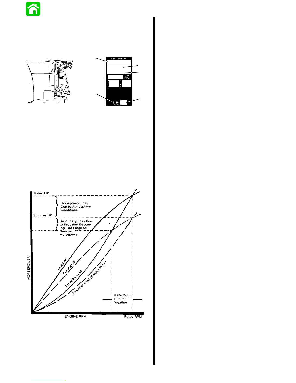
Serial Number Location
The Outboard serial number is located on the lower
starboard side of the engine block. A serial number
is also located on the starboard side of the swivel
bracket.
a
OGXXXXXX
19XX
XXXX
b
c
e
XX
a - Serial Number
b - Model Year
c - Model Description
d - Year Manufactured
e - Certified Europe Insignia
d
Conditions Affecting
Performance
Weather
Corporations internationally have settled on adoption of I.S.O. (International Standards Organization)
engine test standards, as set forth in I.S.O. 3046
standardizing the computation of horsepower from
data obtained on the dynamometer, correcting all values to the power that the engine will produce at sea
level, at 30% relative humidity at 77° F (25° C) temperature and a barometric pressure of 29.61 inches
of mercury.
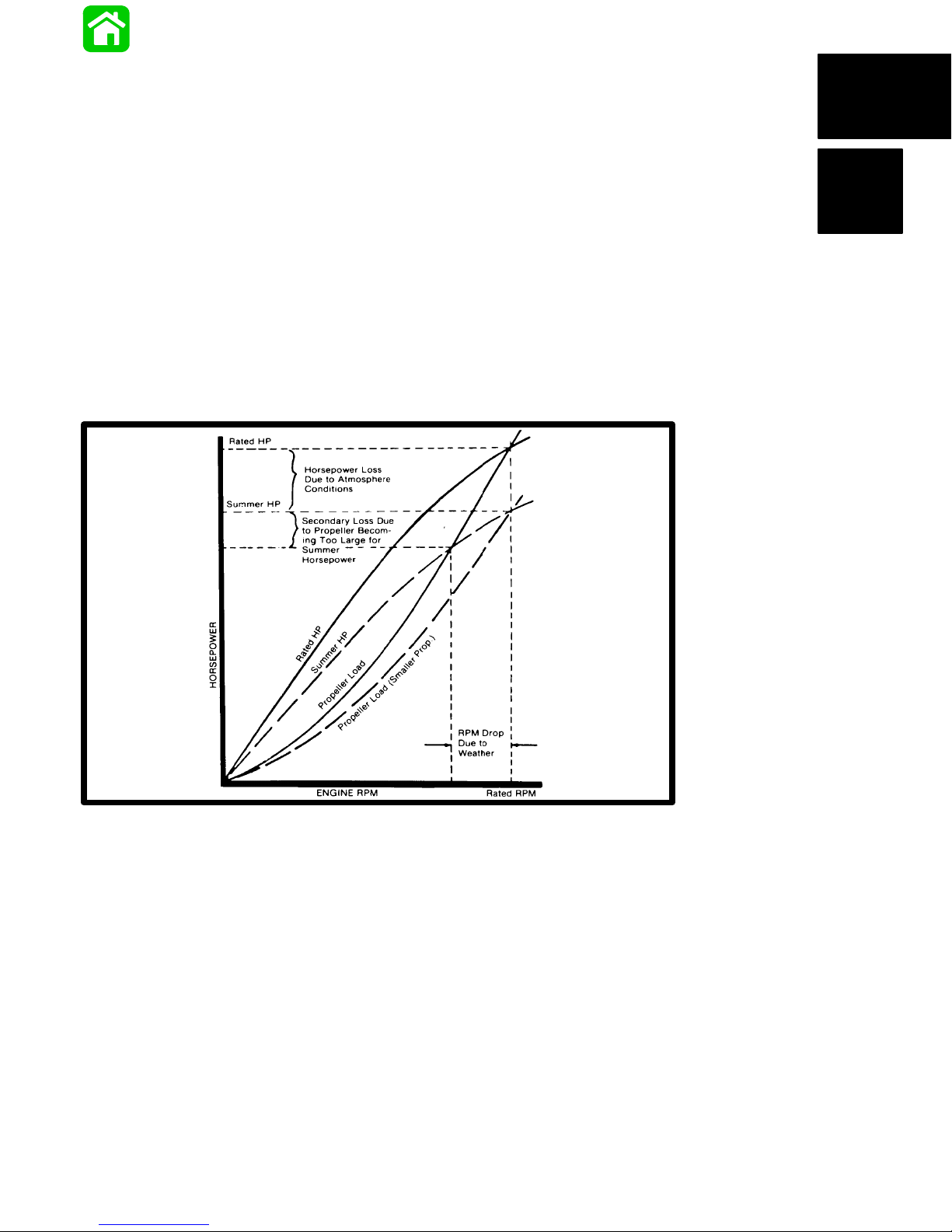
Summer Conditions of high temperature, low barometric pressure and high humidity all combine to reduce the engine power. This, in turn, is reflected in
decreased boat speeds--as much as 2 or 3 milesper-hour (3 or 5 Km per-hour) in some cases. (Refer
to previous chart.) Nothing will regain this speed for
the boater, but the coming of cool, dry weather.
In pointing out the practical consequences of weather effects, an engine--running on a hot, humid summer day--may encounter a loss of as much as 14%
of the horsepower it would produce on a dry, brisk
spring or fall day. The horsepower, that any internal
combustion engine produces, depends upon the
density of the air that it consumes and, in turn, this
density is dependent upon the temperature of the air ,
its barometric pressure and water vapor (or humidity)
content.
Accompanying this weather-inspired loss of power is
a second but more subtle loss. At rigging time in early
spring, the engine was equipped with a propeller that
allowed the engine to turn within its recommended
RPM range at full throttle. With the coming of the
summer weather and the consequent drop in available horsepower, this propeller will, in ef fect, become
too large. Consequently , the engine operates at less
than its recommended RPM.
It is a known fact that weather conditions exert a profound effect on power output of internal combustion
engines. Therefore, established horsepower ratings
refer to the power that the engine will produce at its
rated RPM under a specific combination of weather
conditions.
90-830234R3 DECEMBER 1997 IMPORTANT INFORMATION - 1C-1
Due to the horsepower/RPM characteristics of an engine, this will result in further loss of horsepower at
the propeller with another decrease in boat speed.
This secondary loss, however, can be regained by
switching to a smaller pitch propeller that allows the
engine to again run at recommended RPM.
For boaters to realize optimum engine performance
under changing weather conditions, it is essential
that the engine have the proper propeller to allow it
to operate at or near the top end of the recommended
maximum RPM range at wide-open-throttle with a
normal boat load.
Not only does this allow the engine to develop full
power, but equally important is the fact that the engine also will be operating in an RPM range that discourages damaging detonation. This, of course, enhances overall reliability and durability of the engine.
Page 16

B
Boat
WEIGHT DISTRIBUTION
1. Proper positioning of the weight inside the boat
(persons and gear) has a significant effect on the
boat’s performance, for example:
a. Shifting weight to the rear (stern)
(1.)Generally increases top speed.
(2.) If in excess, can cause the boat to por-
poise.
(3.)Can make the bow bounce excessively in
choppy water.
(4.)Will increase the danger of the following
- wave splashing into the boat when coming off plane.
b. Shifting weight to the front (bow)
WATER ABSORPTION
It is imperative that all through hull fasteners be
coated with a quality marine sealer at time of installation. Water intrusion into the transom core and/or inner hull will result in additional boat weight (reduced
boat performance), hull decay and eventual structural failure.
CAVITATION
Cavitation is caused by water vapor bubbles forming
either from a sharp edge or angle on the gear case
or from an irregularity in the propeller blade itself.
These vapor bubbles flow back and collapse when
striking the surface of the propeller blade resulting in
the erosion of the propeller blade surface. If allowed
to continue, eventual blade failure (breakage) will
occur.
(1.)Improves ease of planing off.
(2.)Generally improves rough water ride.
(3.)If excessive, can make the boat veer left
and right (bow steer).
BOTTOM
For maximum speed, a boat bottom should be
nearly a flat plane where it contacts the water and
particularly straight and smooth in fore-and-aft direction.
1. Hook: Exists when bottom is concave in fore-
and-aft direction when viewed from the side.
When boat is planing, “hook” causes more lift on
bottom near transom and allows bow to drop,
thus greatly increasing wetted surface and reducing boat speed. “Hook” frequently is caused
by supporting boat too far ahead of transom while
hauling on a trailer or during storage.
2. Rocker: The reverse of hook and much less
common. “Rocker” exists if bottom is convex in
fore-and-aft direction when viewed from the side,
and boat has strong tendency to porpoise.
3. Surface Roughness: Moss, barnacles, etc., on
boat or corrosion of outboard’s gear housing increase skin friction and cause speed loss. Clean
surfaces when necessary.
Engine
DETONATION
Detonation in a 2-cycle engine resembles the “pinging” heard in an automobile engine. It can be otherwise described as a tin-like “rattling” or “plinking”
sound.
Detonation is an explosion of an unburned portion of
the fuel/air charge after the spark plug has fired. Detonation creates severe shock waves in the engine,
and these shock waves often find or create a weakness: The dome of a piston, cylinder head/gasket,
piston rings or piston ring lands, piston pin and roller
bearings.
A few of the most common causes of detonation in a
marine 2-cycle application are as follows:
• Over-advanced ignition timing.
• Use of low octane gasoline.
• Propeller pitch too high (engine RPM below rec-
ommended maximum range).
• Lean fuel mixture at or near wide-open-throttle.
• Spark plugs (heat range too hot - incorrect reach
- cross-firing).
• Inadequate engine cooling (deteriorated cooling
system).
• Combustion chamber/piston deposits (result in
higher compression ratio).
90-830234R3 DECEMBER 19971C-2 - IMPORTANT INFORMATION NOVEM
Page 17
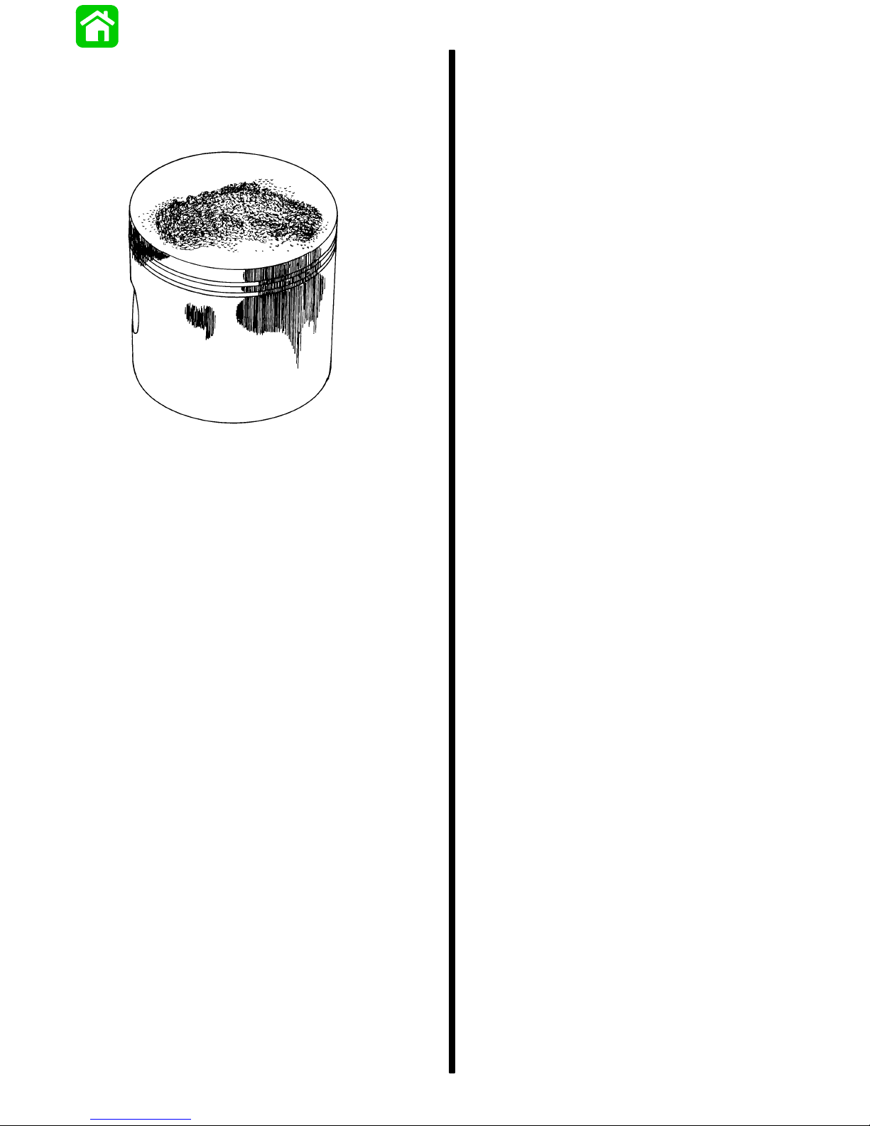
Detonation usually can be prevented if:
1. The engine is correctly set up.
Fresh Water Submersion (Special
Instructions)
2. Diligent maintenance is applied to combat the
detonation causes.
51115
Damaged Piston Resulting from Detonation
Following Complete
Submersion
Submerged While Running (Special
Instructions)
1. Recover engine as quickly as possible.
2. Remove cowling.
3. Flush exterior of outboard with fresh water to remove mud, weeds, etc. DO NOT attempt to start
engine if sand has entered powerhead, as powerhead will be severely damaged. Disassemble
powerhead if necessary to clean components.
4. Remove spark plugs and get as much water as
possible out of powerhead. Most water can be
eliminated by placing engine in a horizontal position (with spark plug holes down) and rotating flywheel.
5. Pour alcohol into carburetor throats (alcohol will
absorbed water). Again rotate flywheel.
6. Turn engine over and pour alcohol into spark plug
openings and rotate flywheel.
7. Turn engine over (place spark plug openings
down) and pour engine oil into throat of carburetors while rotating flywheel to distribute oil
throughout crankcase.
8. Again turn engine over and pour approximately
one teaspoon of engine oil into each spark plug
opening. Again rotate flywheel to distribute oil in
cylinders.
9. Remove and clean carburetors and fuel pump
assembly.
When an engine is submerged while running, the
possibility of internal engine damage is greatly increased. If, after engine is recovered and with spark
plugs removed, engine fails to turn over freely when
turning flywheel, the possibility of internal damage
(bent connecting rod and/or bent crankshaft) exists.
If this is the case, the powerhead must be disassembled.
Salt Water Submersion (Special
Instructions)
Due to the corrosive effect of salt water on internal
engine components, complete disassembly is necessary before any attempt is made to start the engine.
10. Dry all wiring and electrical components using
compressed air.
1 1. Disassemble the engine starter motor and dry the
brush contacts, armature and other corrodible
parts.
12. Reinstall spark plugs, carburetors and fuel pump.
13. Attempt to start engine, using a fresh fuel source.
If engine starts, it should be run for at least one
hour to eliminate any water in engine.
14. If engine fails to start, determine cause (fuel,
electrical or mechanical). Engine should be run
within 2 hours after recovery of outboard from
water, or serious internal damage may occur. If
unable to start engine in this period, disassemble
engine and clean all parts. Apply oil as soon as
possible.
90-830234R3 DECEMBER 1997 IMPORTANT INFORMATION - 1C-3
Page 18
B
Propeller Selection
For in-depth information on marine propellers and
boat performance - written by marine engineers - see
your Authorized Dealer for the illustrated “What Y ou
Should Know About Quicksilver Propellers... and
Boat Performance Information” (Part No.
90-86144).
For best all around performance from your outboard/
boat combination, select a propeller that allows the
engine to operate in the upper half of the recommended full throttle RPM range with the boat normally loaded (refer to Specifications). This RPM range
allows for better acceleration while maintaining maximum boat speed.
3. After initial propeller installation, the following
common conditions may require that the propeller be changed to a lower pitch:
a. Warmer weather and great humidity will
cause an RPM loss.
b. Operating in a higher elevation causes an
RPM loss.
c. Operating with a damaged propeller or a dirty
boat bottom or gear housing will cause an
RPM loss.
d. Operation with an increased load (additional
passengers, equipment, pulling skiers, etc.).
If changing conditions cause the RPM to drop below
the recommended range (such as warmer, more humid weather, operation at higher elevations, increased boat load or a dirty boat bottom/gear case)
a propeller change or cleaning may be required to
maintain performance and ensure the outboard’s durability .
Check full-throttle RPM using an accurate tachometer with the engine trimmed out to a balanced-steering condition (steering effort equal in both directions)
without causing the propeller to “break loose”.
Refer to “Quicksilver Accessory Guide” for a complete list of available propellers.
1. Select a propeller that will allow the engine to operate at or near the top of the recommended full
throttle RPM range (listed in “Specifications,”
preceding) with a normal load. Maximum engine
speed (RPM) for propeller selection exists when
boat speed is maximum and trim is minimum for
that speed. (High RPM, caused by an excessive
trim angle, should not be used in determining correct propeller.) Normally , there is a 150-350 RPM
change between propeller pitches.
2. If full throttle operation is below the recommended range, the propeller MUST BE changed
to one with a lower pitch to prevent loss of performance and possible engine damage.
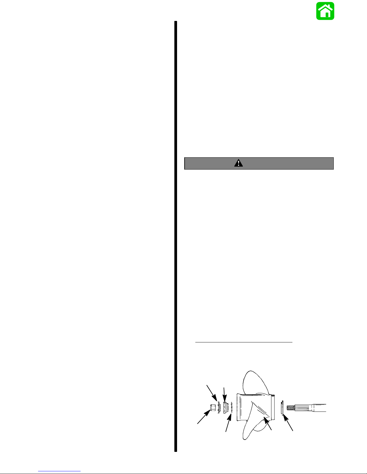
Propeller Installation
WARNING
If the propeller shaft is rotated while the engine
is in gear, there is the possibility that the engine
will crank over and start. To prevent this type of
accidental engine starting and possible serious
injury caused from being struck by a rotating propeller, always shift outboard to neutral position
and remove spark plug leads when you are servicing the propeller.
1. Shift outboard to neutral (N) position.
2. Remove leads from spark plugs to prevent engine from starting.
3. Coat the propeller shaft with Quicksilver Anti–
Corrosion Grease.
IMPORTANT: To prevent the propeller hub from
corroding and seizing to the propeller shaft, especially in salt water, always apply a coat of
Quicksilver Anti-Corrosion Grease to the entire
shaft at the recommended maintenance intervals
and also each time the propeller is removed.
4. Flo-Torque I Drive Hub Propellers
washer (a), propeller (b), continuity washer (c),
thrust hub (d), propeller nut retainer (e), and propeller nut (f) onto the shaft.
– Install thrust
e
d
f
c
90-830234R3 DECEMBER 19971C-4 - IMPORTANT INFORMATION NOVEM
b
a
Page 19

5. Flo-Torque II Drive Hub Propellers – Install forward thrust hub (a), replaceable drive sleeve (b),
propeller (c), thrust hub (d), propeller nut retainer
(e) and propeller nut (f) onto the shaft.
can result in loss of boat control as the outboard
can turn freely . The boat can now “spin out” or go
into a very tight maximum turn which, if unexpected, can result in occupants being thrown
within the boat or out of the boat.
e
f
d
6. Place a block of wood between gear case and
propeller and torque propeller nut to 55 lb. ft. (75
N·m).
7. Secure propeller nut by bending three of the tabs
into the thrust hub grooves.
b
c
a
Power Trim System
General Information
The power trim system is filled at the manufacturer
and is ready for use.
Trim outboard through entire trim and tilt range several times to remove any air from the system.
The trim system is pressurized and is not externally
vented.
Consider the following lists carefully:
TRIMMING IN OR DOWN CAN:
1. Lower the bow.
2. Result in quicker planing off, especially with a
heavy load or a stern heavy boat.
3. Generally improve the ride in choppy water.
4. Increase steering torque or pull to the right (with
the normal right hand rotation propeller).
5. In excess, lower the bow of some boats to a point
where they begin to plow with their bow in the water while on plane. This can result in an unexpected turn in either direction called “bow steering” or “over steering” if any turn is attempted or if
a significant wave is encountered.
WARNING
Avoid possible serious injury or death. Adjust
outboard to an intermediate trim position as
soon as boat is on plane to avoid possible ejection due to boat spin-out. Do not attempt to turn
boat when on plane if outboard is trimmed extremely in or down and there is a pull on the steering wheel or tiller handle.
Power Trim Operation
With most boats, operating around the middle of the
“trim” range will give satisfactory results. However, to
take full advantage of the trimming capability there
may be times when you choose to trim your outboard
all the way in or out. Along with an improvement in
some performance aspects comes a greater responsibility for the operator, and this is being aware of
some potential control hazards. The most significant
control hazard is a pull or “torque” that can be felt on
the steering wheel or tiller handle. This steering
torque results from the outboard being trimmed so
that the propeller shaft is not parallel to the water surface.
W ARNING
Avoid possible serious injury or death. When the
outboard is trimmed in or out beyond a neutral
steering condition, a pull on the steering wheel or
tiller handle in either direction may result. Failure
to keep a continuous firm grip on the steering
wheel or tiller handle when this condition exists
TRIMMING OUT OR UP CAN:
1. Lift the bow higher out of the water.
2. Generally increase top speed.
3. Increase clearance over submerged objects or a
shallow bottom.
4. Increase steering torque or pull to the left at a normal installation height (with the normal right hand
rotation propeller).
5. In excess, cause boat “porpoising” (bouncing) or
propeller ventilation.
6. Cause engine overheating if any water intake
holes are above the water line.
90-830234R3 DECEMBER 1997 IMPORTANT INFORMATION - 1C-5
Page 20
B
Trim “In” Angle Adjustment
Compression Check
Some outboard boats, particularly some bass boats,
are built with a greater than normal transom angle
which will allow the outboard to be trimmed further
“in” or “under”. This greater trim “under” capability is
desirable to improve acceleration, reduce the angle
and time spent in a bow high boat, altitude during
planing off, and in some cases, may be necessary to
plane off a boat with aft live wells, given the variety of
available propellers and height range of engine installations.
However, once on plane, the engine should be
trimmed to a more intermediate position to a avoid a
bow-down planing condition called “plowing”. Plowing can cause “bow steering” or “over steering” and
inefficiently consumes horsepower . In this condition,
if attempting a turn or encountering a diagonal, moderate wake, a more abrupt turn than intended may result.
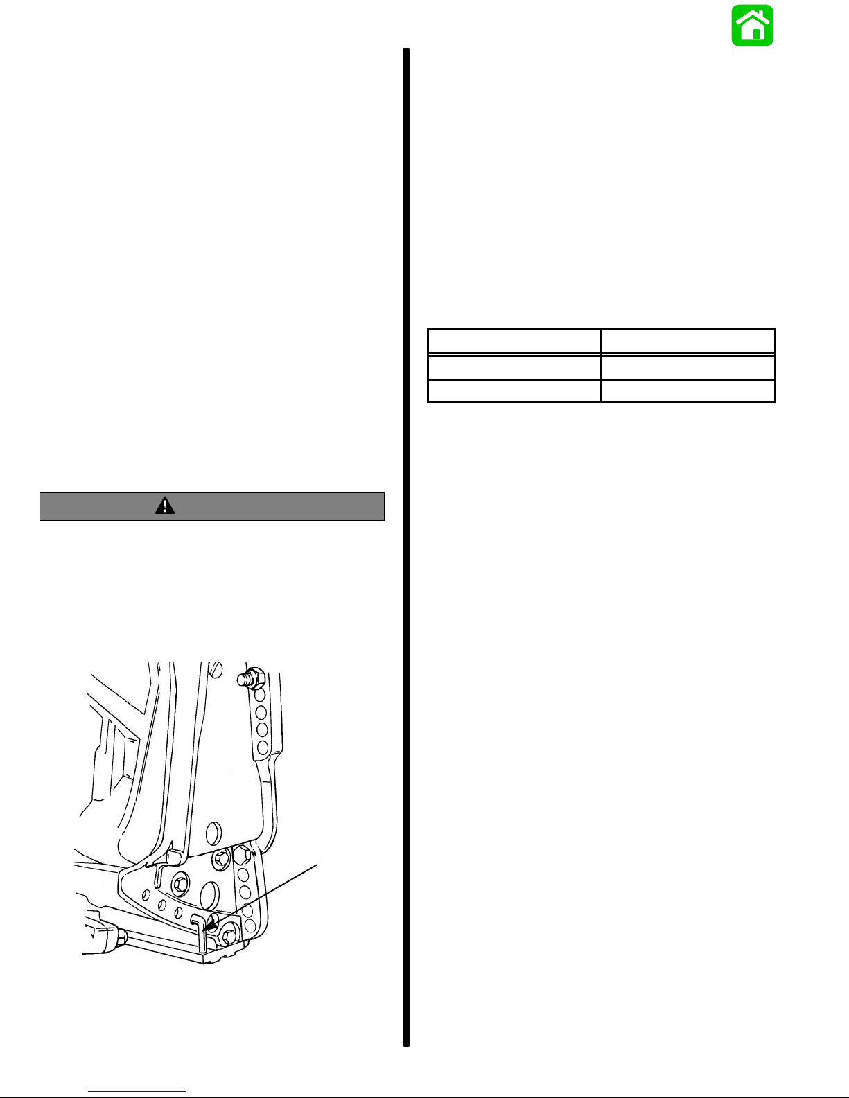
In rare circumstances, the owner may decide to limit
the trim in. This can be accomplished by repositioning the tilt stop pins into whatever adjustment holes
in the transom brackets is desired.
WARNING
1. Remove spark plugs.
2. Install compression gauge in spark plug hole.
3. Hold throttle plate at W.O.T.
4. Crank the engine over until the compression
reading peaks on the gauge. Record the reading.
5. Check and record compression of each cylinder.
The highest and lowest reading recorded should
not differ by more than 15% (see example chart
below). A reading below 120 psi might indicate a
total engine wear problem.
Example of compression test differences
Maximum (psi)
180 162
150 127.5
6. Compression check is important because an
engine with low or uneven compression cannot
be tuned successfully to give peak performance.
It is essential, therefore, that improper compression be corrected before proceeding with an
engine tuneup.
Minimum (psi)
Avoid possible serious injury or death. Adjust
outboard to an intermediate trim position as
soon as boat is on plane to avoid possible ejection due to boat spin-out. Do not attempt to turn
boat when on plane if outboard is trimmed extremely in or down and there is a pull on the steering wheel or tiller handle.
a
7. Cylinder scoring: If powerhead shows any indication of overheating, such as discolored or
scorched paint, visually inspect cylinders for
scoring or other damage as outlined in Section 4
“Powerhead.”
a - Stainless Steel T ilt Pin (P/N 17-49930A1)
90-830234R3 DECEMBER 19971C-6 - IMPORTANT INFORMATION NOVEM
Page 21
Painting Procedures
3. Sand blistered area with 3M 180 grit sandpaper
or P180 Gold Film Disc to remove paint blisters
only. Feather edge all broken paint edges.
Cleaning & Painting Aluminum
Propellers & Gear Housings
WARNING
Avoid serious injury from flying debris. A void serious injury from airborne particles. Use eye and
breathing protection with proper ventilation.
PROPELLERS
1. Sand the entire area to be painted with 3M 120
Regalite Polycut or coarse Scotch-Brite, disc or
belts.
2. Feather edges of all broken paint edges. Try not
to sand through the primer.
3. Clean the surface to be painted using PPG
Industries DX330 Wax and Grease Remover or
equivalent (Xylene or M.E.K.).
4. If bare metal has been exposed, use Quicksilver’s Light Gray Primer.
5. Allow a minimum of 1 hour dry time and no more
than 1 week before applying the finish coat.
6. Apply the finish coat using Quicksilver’s EDP
Propeller Black.
GEAR HOUSINGS
The following procedures should be used in refinishing gear housings. This procedure will provide the
most durable paint system available in the field. The
materials recommended are of high quality and
approximate marine requirements. The following
procedure will provide a repaint job that compares
with a properly applied factory paint finish. It is recommended that the listed materials be purchased
from a local Ditzler Automotive Finish Supply Outlet.
The minimum package quantity of each material
shown following is sufficient to refinish several gear
housings.
Procedure:
4. Clean gear housing thoroughly with (DX-330)
wax and grease remover.
5. Spot repair surfaces where bare metal is exposed with (DX-503) alodine treatment.
IMPORTANT: Do not use any type of aerosol
spray paints as the paint will not properly adhere
to the surface nor will the coating be sufficiently
thick to resist future paint blistering.
6. Mix epoxy chromate primer (DP-40) with equal
part catalyst (DP-401) per manufacturers
instructions, allowing proper induction period for
permeation of the epoxy primer and catalyst.
7. Allow a minimum of one hour drying time and no
more than one week before top coating assemblies.
8. Use Ditzler Urethane DU9000 for Mercury Black,
DU34334 for Mariner Grey, and DU35466 for
Force Charcoal, and DU33414M for Sea Ray
White. Catalyze all three colors with Ditzler DU5
catalyst mixed 1:1 ratio. Reduce with solvents
per Ditzler label.
CAUTION
Be sure to comply with instructions on the label
for ventilation and respirators. Using a spray
gun, apply one half to one mil even film thickness. Let dry , flash off for five minutes and apply
another even coat of one half to one mil film thickness. This urethane paint will dry to the touch in
a matter of hours, but will remain sensitive to
scratches and abrasions for a few days.
9. The type of spray gun used will determine the
proper reduction ratio of the paint.
IMPORT ANT : Do not paint sacrificial zinc trim tab
or zinc anode.
10. Cut out a cardboard “plug” for trim tab pocket to
keep paint off of mating surface to maintain good
continuity circuitry between trim tab and gear
housing.
1. Wash gear housing with a muriatic acid base
cleaner to remove any type of marine growth,
and rinse with water, if necessary.
2. Wash gear housing with soap and water, then
rinse.
90-830234R3 DECEMBER 1997 IMPORTANT INFORMATION - 1C-7
Page 22

B
Decal Application
Decal Removal
DECAL APPLICATION
1
1. Mix
/2 ounce (16 ml) of dish washing liquid in one
gallon (4 l) of cool water to use as wetting solution.
1. Mark decal location before removal to assure
proper alignment of new decal.
2. Carefully soften decal and decal adhesive with a
heat gun or heat blower while removing old decal.
3. Clean decal contact area with a 1:1 mixture of isopropyl alcohol and water.
4. Thoroughly dry decal contact area and check for
a completely cleaned surface.
Instructions for “Wet” Application
NOTE: The following decal installation instructions
are provided for a “Wet” installation. All decals
should be applied wet.
TOOLS REQUIRED
1. Plastic Squeegee*
2. Stick Pin
3. Dish Washing Liquid/Detergent without am-
monia** “Joy” and “Drift” are known to be compatible for this process.
** Automotive Body Filler Squeegee
** Do not use a soap that contains petroleum based
solvents.
SERVICE TIP: Placement of decals using the
“Wet” application will allow time to position decal. Read entire installation instructions on this
technique before proceeding.
NOTE: Leave protective masking, if present, on the
face of decal until final steps of decal installation. This
will ensure that the vinyl decal keeps it’s shape during
installation.
2. Place the decal face down on a clean work surface and remove the paper backing from “adhesive side” of decal.
3. Using a spray bottle, flood the entire “adhesive
side” of the decal with the pre-mixed wetting solution.
4. Flood area where the decal will be positioned
with wetting solution.
5. Position pre-wetted decal on wetted surface and
slide into position.
6. Starting at the center of the decal, “lightly”
squeegee out the air bubbles and wetting solution with overlapping strokes to the outer edge of
the decal. Continue going over the decal surface
until all wrinkles are gone and adhesive bonds to
the cowl surface.
7. Wipe decal surface with soft paper towel or cloth.
8. Wait 10 - 15 minutes.
9. Starting at one corner, “carefully and slowly” pull
the masking off the decal surface at a 180° angle.
NOTE: T o remove any remaining bubbles, pierce the
decal at one end of the bubble with stick pin and
press out the entrapped air or wetting solution with
your thumb (moving toward the puncture).
TEMPERATURE
IMPORTANT: Installation of vinyl decals should
not be attempted while in direct sunlight. Air and
surface temperature should be between 60°F
(15°C) and 100°F (38°C) for best application.
SURFACE PREPARATION
IMPORT ANT : Do not use a soap or any petroleum
based solvents to clean application surface.
Clean entire application surface with mild dish washing liquid and water. Rinse surface thoroughly with
clean water.
90-830234R3 DECEMBER 19971C-8 - IMPORTANT INFORMATION NOVEM
Page 23

IMPORTANT
INFORMATION
1
D
OUTBOARD INSTALLATION
Page 24

Table of Contents
Page
Determining Recommended Outboard
Mounting Height 1D-1. . . . . . . . . . . . . . . . . . . . . . . . . . . . .
Notice to Installer and Owner 1D-2. . . . . . . . . . . . . . . . . .
Boat Horsepower Capacity 1D-2. . . . . . . . . . . . . . . . .
Outboard Remote Control 1D-2. . . . . . . . . . . . . . . . . .
Selecting Accessories For The Outboard 1D-2. . . . .
Selecting Steering Cables and Remote Control
Cables 1D-2. . . . . . . . . . . . . . . . . . . . . . . . . . . . . . . . . . .
Locate Center line Of The Outboard 1D-3. . . . . . . . .
Drilling Outboard Mounting Holes 1D-3. . . . . . . . . . . .
Lifting Outboard 1D-4. . . . . . . . . . . . . . . . . . . . . . . . . . .
Fastening Outboard To The Transom 1D-4. . . . . . . .
Single Steering Cable and Steering Link
Rod Installation 1D-5. . . . . . . . . . . . . . . . . . . . . . . . . . . . . .
Installing Ride Guide Steering Cable to the
Outboard 1D-5. . . . . . . . . . . . . . . . . . . . . . . . . . . . . . . . .
Steering Link Rod Installation 1D-5. . . . . . . . . . . . . . .
Co-Pilot Installation (Tiller Handle models) 1D-6. . . . . . .
Remote Control Installation 1D-7. . . . . . . . . . . . . . . . . . . .
Required Side Mount Remote Control or Ignition
Key Switch Assembly 1D-7. . . . . . . . . . . . . . . . . . . . . . . . .
Boats Equipped with Side Mount
Remote Control 1D-7. . . . . . . . . . . . . . . . . . . . . . . . . . .
Boats Equipped with Panel Or Console Mount
Remote Control 1D-7. . . . . . . . . . . . . . . . . . . . . . . . . . .
Connecting Remote Wiring Harness to the Engine 1D-7
Shift and Throttle Cable Installation to the Outboard1D-8
Shift Cable Installation 1D-8. . . . . . . . . . . . . . . . . . . . .
Throttle Cable Installation 1D-9. . . . . . . . . . . . . . . . . .
Battery Connections 1D-10. . . . . . . . . . . . . . . . . . . . . . . . .
Set Up Instructions For Oil Injection System 1D-10. . . .
Filling The Oil Injection System 1D-10. . . . . . . . . . . . .
Bleeding Air From The Oil Injection System 1D-11. .
Adjusting The Oil Injection Pump 1D-11. . . . . . . . . . .
Trim Tab Adjustment 1D-12. . . . . . . . . . . . . . . . . . . . . . . . .
90-830234R3 DECEMBER 19971D-0 - IMPORTANT INFORMATION
Page 25
Notice to Installer and Owner
Outboard Remote Control
This manual as well as safety labels posted on the
outboard use the following safety alerts to draw your
attention to special safety instructions that should be
followed.
W ARNING
WARNING – Hazards or unsafe practices which
COULD result in severe personal injury or death.
CAUTION
CAUTION – Hazards or unsafe practices which could
result in minor injury or product or property damage.
Boat Horsepower Capacity
U.S. COAST GUARD CAPACITY
MAXIMUM HORSEPOWER XXX
MAXIMUM PERSON
CAPACITY (POUNDS) XXX
MAXIMUM WEIGHT
CAPACITY XXX
Do not overpower or overload your boat. Most boats
will carry a required capacity plate indicating the
maximum acceptable power and load as determined
by the manufacturer following certain federal guidelines. If in doubt, contact your dealer or the boat manufacturer.
W ARNING
Using an outboard that exceeds the maximum
horsepower limit of a boat can: 1. cause loss of
boat control 2. place too much weight at the transom altering the designed flotation characteristics of the boat or 3. cause the boat to break apart
particularly around the transom area. Overpowering a boat can result in serious injury , death, or
boat damage.
The remote control connected to your outboard must
be equipped with a start-in-gear protection device.
This prevents the engine from starting when the outboard is in gear.
WARNING
Avoid serious injury or death from a sudden unexpected acceleration when starting your engine. The design of this outboard requires that
the remote control used with it must have a built
in start-in-gear protection device.
Selecting Accessories For
The Outboard
Genuine Mercury Marine Quicksilver Accessories
have been specifically designed and tested for your
outboard.
Mercury Marine Quicksilver accessories are available from Mercury Marine dealers.
Some accessories not manufactured or sold by Mercury Marine are not designed to be safely used with
your outboard or outboard operating system. Acquire
and read the installation, operation, and maintenance manuals for all your selected accessories.
WARNING
Check with your dealer before installation of accessories. The misuse of acceptable accessories or the use of unacceptable accessories can
result in serious injury , death, or product failure.
Selecting Steering Cables
and Remote Control Cables
Refer to “Quicksilver Accessories Guide” to determine correct length of steering cables and remote
control cables.
90-830234R3 DECEMBER 1997 IMPORTANT INFORMATION - 1D-1
IMPORT ANT : Steering cables and remote control
cables must be the correct length. Sharp bends
on too-short cables result in “kinks”; too-long
cables require unnecessary bends and/or loops.
Both conditions place extra stress on the cables.
Page 26
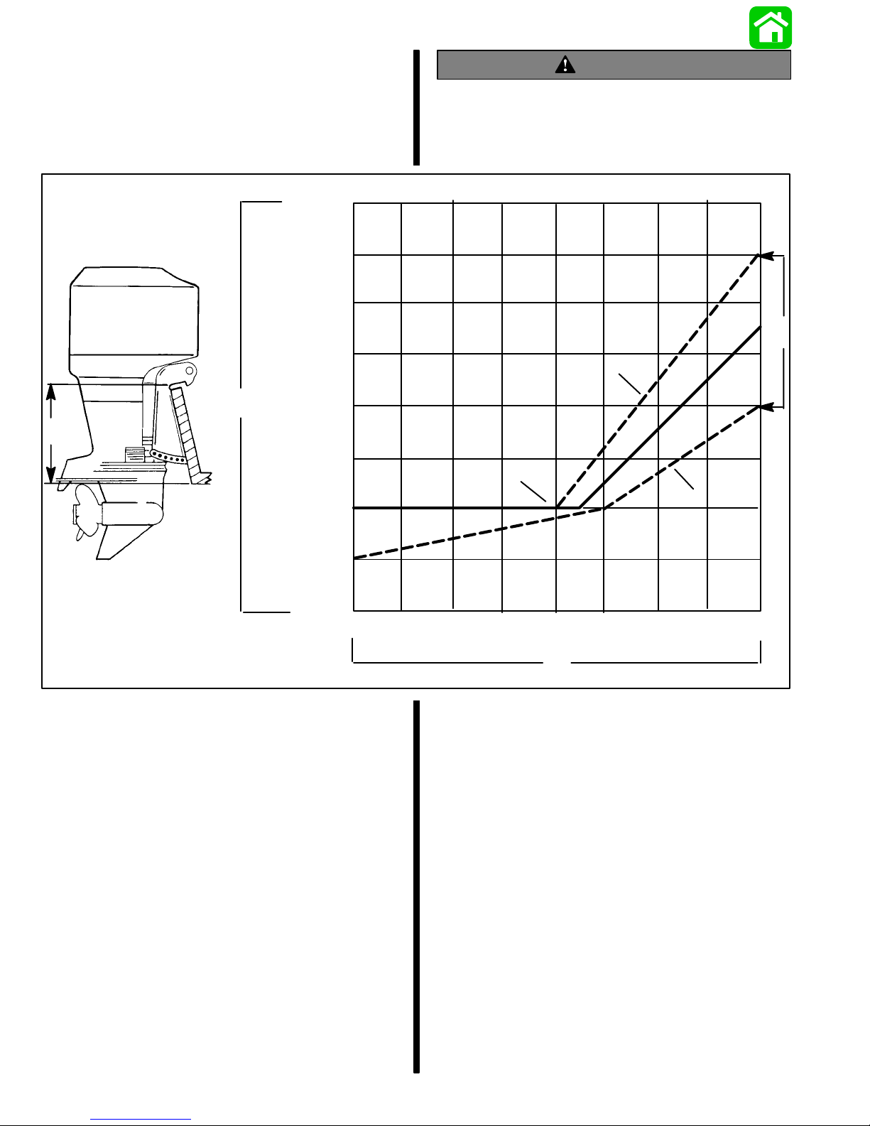
Determining Recommended
WARNING
Outboard Mounting Height
26 in.
(660m
m)
25 in.
(635m
m)
24 in.
(609m
m)
23 in.
(584m
m)
e
e
22 in.
(560m
m)
21 in.
(533m
m)
20 in.
(508m
m)
19 in.
(482m
m)
Boat instability can occur at high speeds by
installing engine at the wrong transom height.
Contact the boat manufacturer for their recommendations for a specific engine installation.
b
c
a
d
10
NOTE: Add 5 in. (127mm) for XL models and 10 in.
(254mm) for XXL models to listed outboard mounting
height.
a. This solid line is recommended to determine
the outboard mounting height.
IMPORTANT: Increasing the height of outboard
generally will provide the following: 1) Less
steering torque, 2) more top speed, 3) greater
boat stability , but, 4) will cause more prop “break
loose” which may be particularly noticeable
when planing off or with heavy load.
b. These broken lines represent the extremes of
known successful outboard mounting height
dimensions.
c. This line may be preferred to determine out-
board mounting height dimension, if maximum speed is the only objective.
20 30 40 50 60 70 80
f
d. This line may be preferred to determine out-
board mounting height dimension for dual
outboard installation.
e. Outboard mounting height (height of out-
board transom brackets from bottom of boat
transom). For heights over 22 in. (560mm), a
propeller, that is specifically designed for surfacing operation, such as the “Laser” and “Mirage” series, usually are preferred.
f. Maximum boat speed anticipated.
90-830234R3 DECEMBER 19971D-2 - IMPORTANT INFORMATION
Page 27
Locating Center Line Of The
Outboard
Locate (and mark with pencil) the vertical centerline
(a) of boat transom.
BA
a
DC
a - Centerline of Transom
NOTE: When drilling into a fiberglass boat, place
masking tape directly onto boat where mounting
holes will be drilled to help prevent fiberglass from
chipping.
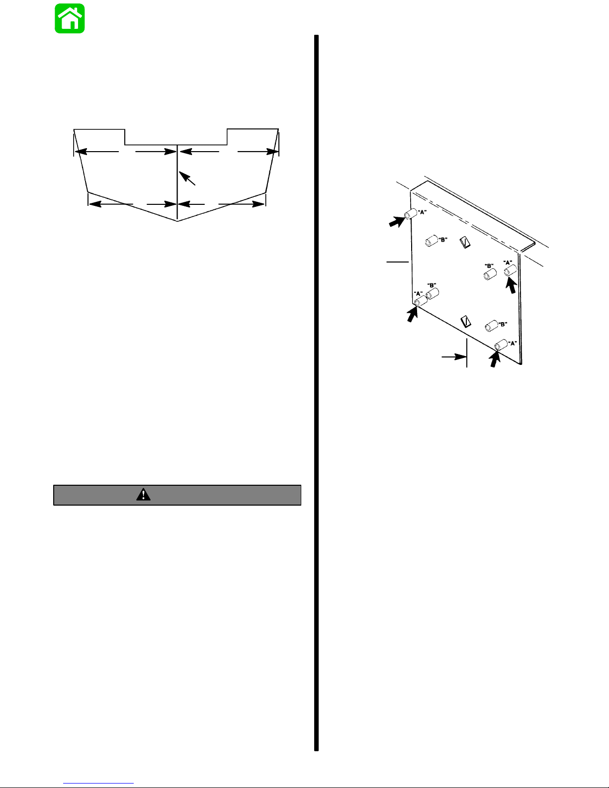
Use a 17/32 inch (13.5mm) diameter drill bit and drill
4 mounting holes perpendicular to and thru transom.
IMPORTANT: If using “Transom Drilling Fixture”
(part number 91–98234A2), use drill guide holes
marked “A” when drilling outboard mounting
holes.
NOTE: Dimensions “A” & “B” and “C” & “D” are equal
length.
IMPORT ANT : During installation of dual outboards,
the following is recommended. A minimum of 221/2
inches (570mm) centerline to centerline width is recommended. This is required to alleviate cowling interference during lock to lock turns if one outboard
would be in the full tilt position, while the other outboard(s) are in the vertical running position.
Drilling Outboard Mounting Holes
IMPORT ANT : Before drilling any mounting holes,
carefully read “Determining Recommended Outboard Mounting Height,” preceding. There is a
3/4 inch (19mm) difference between outboard
mounting holes in transom brackets.
WARNING
DO NOT, under any circumstances, allow upper
outboard mounting bolts to be closer than 1 inch
(25.4mm) from top of boat transom. Upper
mounting bolts must never be installed thru
shims.
b
a
a – Centerline of Transom
b – Transom Drilling Fixture (91–98234A2)
90-830234R3 DECEMBER 1997 IMPORTANT INFORMATION - 1D-3
Page 28
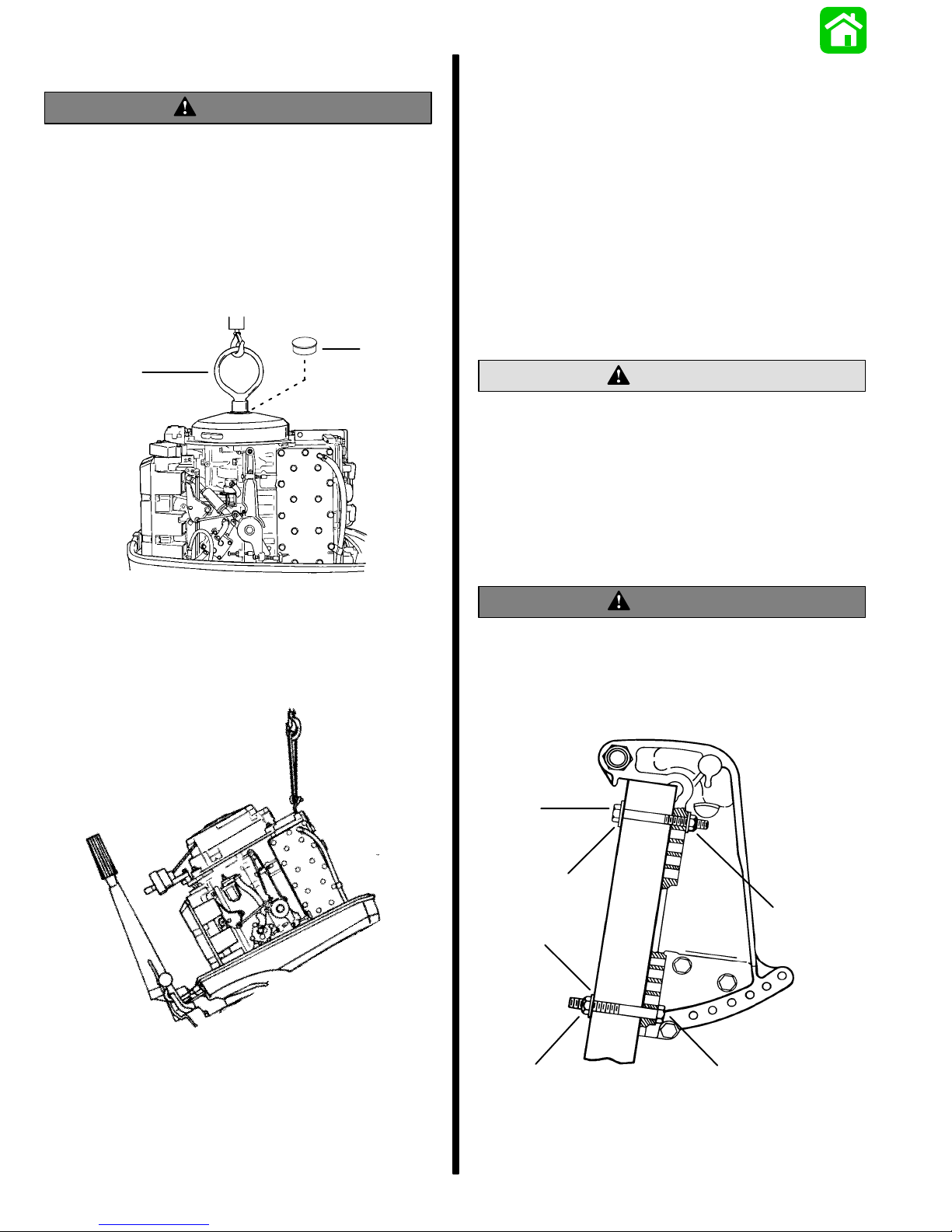
Lifting Outboard
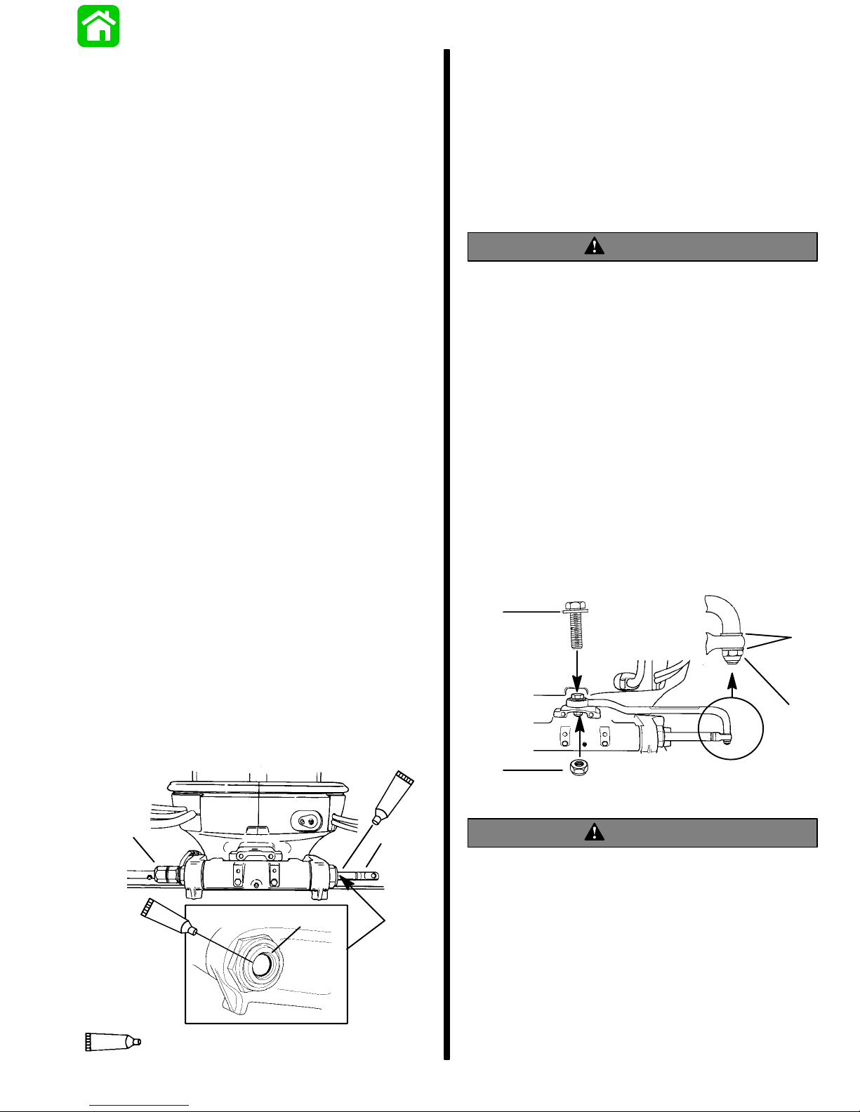
Installing Outboard To Boat
WARNING
Verify that the lifting ring is threaded into the flywheel a minimum of 5 turns and that hoist has a
maximum lift capacity over 500 lbs. (227 kg) BEFORE lifting outboard.
1. Electric Start Models – Remove plastic cap from
center of flywheel. Thread lifting ring into flywheel
hub a minimum of 5 turns. Replace plastic cap after installation.
b
a
Transom
IMPORT ANT : If boat is equipped with thru tilt tube
steering, steering cable end must be installed
into tilt tube of outboard (port outboard only for
dual outboard installations) before securing outboard to transom. Refer to ”Steering Cable and
Steering Link Rod Installation” following.
Refer to “Determining Recommended Outboard Motor Mounting Height”, preceding and position outboard on boat transom, to align mounting holes in
transom bracket that will place the outboard nearest
to the recommended mounting height.
CAUTION
Marine sealer must be used on shanks bolts to
make a water-tight installation.
IMPORT ANT: DO NOT use an impact driver when
tightening transom bolts.
Apply marine sealer to shanks of mounting bolts (not
threads) and secure outboard to transom with 4 bolts,
flat washers and locknuts, as shown. Be sure that installation is water-tight.
a - Lifting Ring
b - Plastic Cap – Replace After Installation
2. Manual Start Models – Use lifting eye on engine
and lift outboard on boat transom.
WARNING
Before operation, the outboard must be correctly
installed with four mounting bolts shown. Failure
to correctly fasten outboard could result in outboard ejecting off boat transom causing serious
injury, death, or property damage.
a
b
c
b
c
a - 1/2 Inch Diameter Bolts
b - Flat W ashers
c - Locknuts
a
90-830234R3 DECEMBER 19971D-4 - IMPORTANT INFORMATION
Page 29
Single Steering Cable and
Steering Link Rod Installation
Steering Link Rod
Installation
NOTE: These instructions are for single cable–single
outboard installations. Instructions for mounting dual
engines are included with the applicable dual engine
attaching kit. Refer to “Quicksilver Accessories
Guide” to determine correct kit.
Refer to “Quicksilver Accessories Guide” to determine correct length of steering cable.
IMPORTANT: Steering cable must be correct
length. Sharp bends on too-short of a cable result in “kinks;” too-long of a cable require unnecessary bends and/or loops. Both conditions
place extra stress on the cable.
Install steering mount and steering wheel in accordance with installation instructions that accompany
each.
Installing Ride Guide Steering Cable
To The Outboard
IMPORTANT: Before installing steering cable in
tilt tube, lubricate entire cable end with Quicksilver 2-4-C Marine Lubricant.
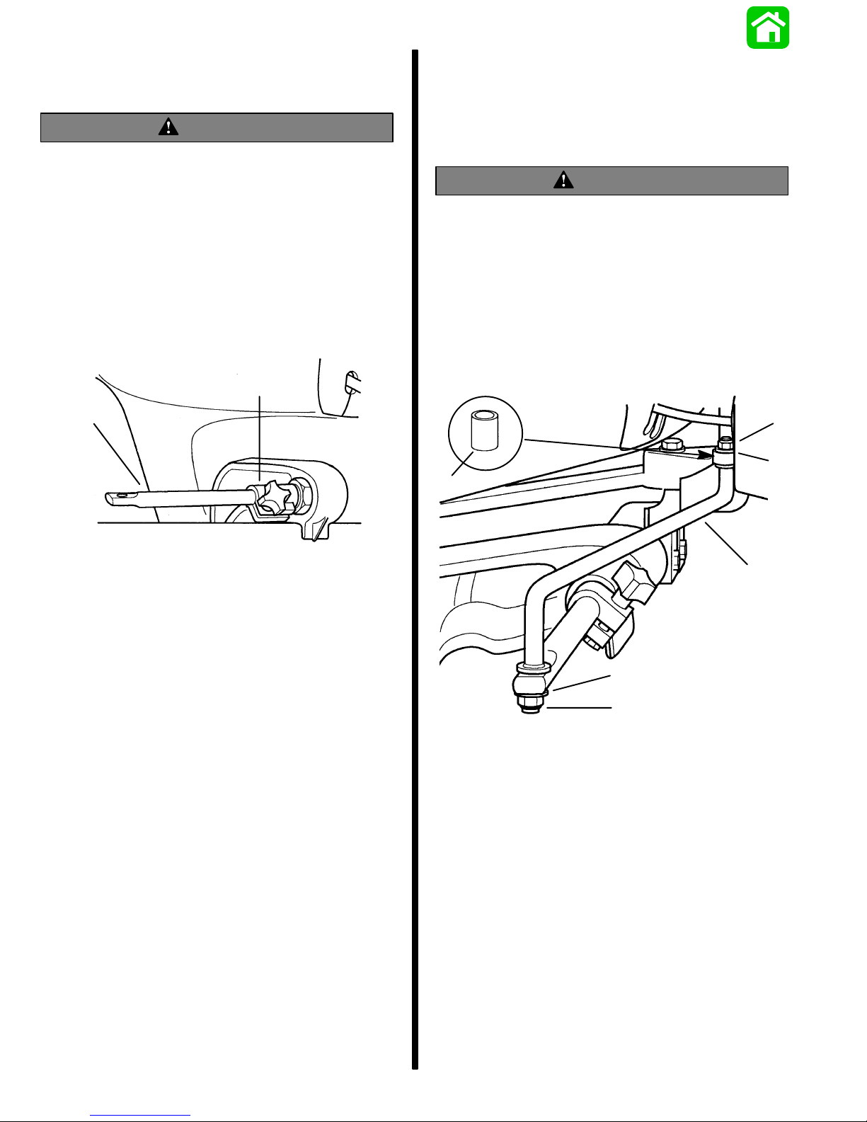
IMPORT ANT: The steering link rod that connects
the steering cable to the engine must be fastened
using special washer head bolt (“a” – Part Number 10-14000) and self locking nuts (“b”& “c”–
Part Number 11-34863). These locknuts must
never be replaced with common nuts (non locking) as they will work loose and vibrate off freeing the link rod to disengage.
WARNING
Disengagement of a steering link rod can result
in the boat taking a full, sudden, sharp turn. This
potentially violent action can cause occupants to
be thrown overboard exposing them to serious
injury or death.
3. Assemble steering link rod to steering cable with
two flat washers (d) and nylon insert locknut (“b”
– Part Number 1 1-34863). Tighten locknut (b) until it seats, then back nut off 1/4 turn.
4. Assemble steering link rod to engine with special
washer head bolt (“a” – Part Number 10-14000)
and nylon insert locknut (“c”– Part Number
11-34863). First torque bolt (a) to 20 lb. ft. (27.0
N·m), then torque locknut (c) to 20 lb. ft. (27.0
N·m).
NOTE: Ride Guide steering cable is lubricated at the
factory and requires no additional lubrication at initial
installation.
1. Lubricate seal (a) inside of outboard tilt tube and
entire cable end (b) with Quicksilver 2-4-C Marine Lubricant.
2. Insert steering cable end thru outboard tilt tube
and secure steering cable to tilt tube with steering
cable attaching nut (c), as shown. Torque nut to
35 lb. ft. (47.5 N·m).
95
c
95
a
b
a
d
b
c
WARNING
After installation is complete (and before operating outboard), check that boat will turn right
when steering wheel is turned right and that boat
will turn left when steering wheel is turned left.
Check steering thru full range (left and right) and
at all tilt angles to assure interference-free movement.
95
90-830234R3 DECEMBER 1997 IMPORTANT INFORMATION - 1D-5
2-4-C With Teflon (92-825407A12)
Page 30
Co-Pilot Installation (Tiller
Handle models)
WARNING
Avoid possible serious injury or death from loss
of boat control. The Co-pilot assembly must be
installed and adjusted to maintain sufficient
steering friction to prevent the outboard from
steering into a full turn if the tiller handle is released.
1. Thread the friction collar (a) onto the starboard
side of the tilt tube. Tighten securely and position
the adjustment knob toward front of outboard.
2. Insert pilot rod (b) into the friction collar.
a
IMPORT ANT : The co-pilot link rod (c) must be fastened using self locking nylon insert locknuts
(“f”& “g”– Part Number 11-45592).These locknuts must never be replaced with common nuts
(non locking) as they will work loose and vibrate
off freeing the link rod to disengage.
WARNING
Disengagement of the co-pilot link rod can result
in the boat taking a full, sudden, sharp turn. This
potentially violent action can cause occupants to
be thrown overboard exposing them to serious
injury or death.
3. Lubricate both ends of the link rod with Quicksilver 2-4-C w/Teflon Marine Lubricant. Install link
rod between the tiller handle mount and pilot rod
as shown.
b
f
e
d
c
e
g
c - Co-Pilot Link Rod
d - Spacer (Hidden) - Place in the Upper Mounting Hole
For The Link Rod.
e - Flat W asher
f - Locknut - Torque to 120 lb. in. (13.6 N·m)
g - Locknut - T ighten Until it Seats; DO NOT exceed 120 lb.
in. (13.6 N·m), Then Back Off The Locknut 1/4 Turn.
90-830234R3 DECEMBER 19971D-6 - IMPORTANT INFORMATION
Page 31

Remote Control Installation
Shift and Throttle Cable
Refer to “Quicksilver Accessories Guide” to determine correct length of remote control cables.
IMPORT ANT : Remote control cables must be correct length. Sharp bends on too-short cables result in “kinks;” too-long cables require unnecessary bends and/or loops. Both conditions place
extra stress on the cables.
IMPORTANT: Install control cables to remote
control and mount remote control BEFORE attaching control cables to engine. Refer to installation instructions included with remote control.
Required Side Mount
Remote Control or Ignition
Key Switch Assembly
Boats Equipped with Side Mount
Remote Control
A Quicksilver Commander 2000 series Side Mount
Remote Control equipped with a warning horn must
be used with this outboard. This warning horn is necessary for the engine warning system.
Installation To The Outboard
Install the shift cable and throttle cable into the remote control and mount the remote control following
instructions which are provided the remote control.
NOTE: Install the shift cable before the throttle cable.
The shift cable is the first cable to move when the remote control handle is moved into gear.
Shift Cable Installation
1. Pull up the cowl seal and remove the port side
rubber grommet (a).
a
2. Position the remote control and outboard into
neutral.
3. Slide shift actuator (b) toward the rear of engine
(reverse gear) until resistance is felt. Measure
distance (c) between mounting stud and barrel
retainer.
a
a -Warning Horn
Boats Equipped with Panel Or
Console Mount Remote Control
A Quicksilver Ignition Key/Choke Assembly
equipped with a warning horn must be used with this
engine. This warning horn is necessary for the engine warning system.
a
4. Push the cable end (d) in (towards cable barrel)
until resistance is felt. Adjust the cable barrel (e)
to attain distance (c).
e
d
c
b
a - Warning Horn
90-830234R3 DECEMBER 1997 IMPORTANT INFORMATION - 1D-7
Page 32

5. Place cable barrel into retainer and fasten the
cable end to mounting stud with nylon washer (f)
and locknut (g). Tighten locknut against the nylon
washer, then back-off the locknut 1/4 turn.
6. Check shift cable adjustments as follows:
a. With remote control in forward the propshaft
should lock solidly in gear. If it does not, adjust the cable barrel closer to the cable end
guide.
3. Adjust throttle cable barrel (b) so the barrel will be
able to slip into the retainer when the cable end
is on the mounting stud and there is a slight preload against the stop.
4. Check preload on throttle cable by placing a thin
piece of paper between adjustment screw and
stop. Preload is correct when the paper can be removed without tearing, but has some drag in it.
Readjust cable barrel if necessary.
5. Place the throttle cable barrel into the top retainer
hole and the cable end on the cable mounting
stud. Fasten throttle cable to the mounting stud
with nylon washer (c) and locknut (d). Tighten
locknut against the nylon washer, then back-off
the locknut 1/4 turn.
6. Lock the cable barrels in-place with cable latch
(e).
b. Shift remote control into neutral. The prop-
shaft should turn freely without drag. If not,
adjust the barrel away from the cable end
guide. Repeat steps a and b.
c. Shift remote control into reverse while turning
propeller. The propshaft should lock solidly in
gear. If not, adjust the barrel away from the
cable end guide. Repeat steps a thru c.
d. Return remote control handle to neutral. The
propeller should turn freely without drag. If
not, adjust the barrel closer to the cable end
guide. Repeat steps a thru d.
Throttle Cable Installation
NOTE: Attach Shift cable to engine prior to attaching
throttle cable.
1. Position the remote control handle into neutral
detent.
2. Position adjustment screw (a) against the stop.
a
b
d
c
e
7. Lubricate the port side rubber grommet and reinstall into cowl. Slip the grommet over the control
cables. Push the cowl seal back into place.
90-830234R3 DECEMBER 19971D-8 - IMPORTANT INFORMATION
Page 33

NOTE: The rubber grommet has to be lubricated to
ease installation.
f
f
f – Lubricant
Connecting Remote Wiring
Harness To The Engine
1. Pull up the cowl seal (a) and remove the starboard side rubber grommet (b).
b
a
2. Take hold of the engine connector (c) and install
the remote wiring harness plug (d). Connect
additional wire leads (if equipped) as shown.
NOTE: The rubber grommet can to be lubricated to
ease installation.
90-830234R3 DECEMBER 1997 IMPORTANT INFORMATION - 1D-9
c
d
Page 34

3. Push the connector and plug into the holder (e).
e
Battery Connections
CAUTION
For dual outboard installations, the black (–) battery cable of each engines starter motor ground
circuit, MUST BE connected to each other by a
common circuit (cable) capable of carrying the
starting current of each engine’s starter motor.
[i.e. A locally obtained battery cable connected
between the negative (–) terminal of each outboards cranking battery].
CAUTION
Failure to observe correct polarity when connecting battery cables to battery, will result in
damage to the charging system.
4. Insert the battery cables and remote wiring harness into the rubber grommet. Reinstall the starboard side rubber grommet into the cowl. Push
the cowl seal back in place.
1. Connect battery cables (from engine) to battery.
Connect red battery cable to positive terminal
and black battery cable to negative (–) battery
terminal.
Set Up Instructions For Oil
Injection System
CAUTION
Oil injected engines additionally , must be run on
a 50:1 gasoline/oil mixture during the engine
break-in period. Refer to engine break-in procedure in the Operation & Maintenance Manual.
CAUTION
If an electric fuel pump is to be used on engines
with oil injection, the fuel pressure at the engine
must not exceed 4 psig. If necessary, install a
pressure regulator between electrical fuel pump
and engine and set at 4 psig maximum.
90-830234R3 DECEMBER 19971D-10 - IMPORTANT INFORMATION
Page 35

Filling The Oil Injection System
1. Open the cowl cap (a). Turn the oil fill cap (b) to
the left and remove.
a
Bleeding Air From The Oil Injection
System
IMPORT ANT : If air exists in either the oil pump inlet hose (a) or oil pump outlet hose (b), the air
MUST BE bled from the hose(s) or engine damage may occur.
BLEEDING AIR FROM THE OIL PUMP INLET
HOSE
b
2. Use the dipstick (c) to check oil level.
3. Hook the dipstick (d) on the tank during filling.
c
d
4. Slowly fill the oil tank with the specified oil. Do Not
overfill – add only enough oil to bring the oil level
up to the bottom of the fill neck (e).
Note:The oil tank capacity for three cylinder models
is 3.2 qt. (3.0 liters) and four cylinder models is 5.13
qt. (4.9 liters).
5. Install oil filler cap (b) and re-tighten. Reinstall the
cowl cap.
1. With the engine not running, place a shop towel
below the oil pump.
2. Loosen bleed screw (c) four turns and allow oil to
flow out of the bleed hole until no air bubbles exist
in the inlet hose (a).
BLEEDING AIR FROM THE OIL PUMP OUTLET
HOSE
3. If any air bubbles are present in the outlet hose
(b), they can be purged from the hose by removing link rod (d) from the oil pump and rotating the
pump arm (e) full clockwise while operating engine at 1000 to 1500 RPM.
b
c
e
b
FULL
90-830234R3 DECEMBER 1997 IMPORTANT INFORMATION - 1D-11
a
d
e
Page 36

Adjusting The Oil Injection Pump
Trim Tab Adjustment
When carburetor linkage is at idle position, alignment
mark (a) on oil injection arm should be in-line with
mark (b) on pump as shown. If necessary , adjust link
rod (c).
b
Propeller steering torque will cause your boat to pull
in one direction. This steering torque is a normal thing
that results from your outboard not being trimmed so
the propeller shaft is parallel to the water surface.
The trim tab can help to compensate for this steering
torque in many cases and can be adjusted within limits to reduce any unequal steering effort.
NOTE: Trim tab adjustment will have little effect reducing steering torque if the outboard is installed with
the anti-ventilation plate approximately 2 inches
(50mm) or more above the boat bottom.
Operate your boat at normal cruising speed, trimmed
to desired position. Turn your boat left and right and
note the direction the boat turns more easily.
If adjustment is necessary, loosen trim tab bolt and
make small adjustments at a time. If the boat turns
more easily to the left, move the trailing edge of trim
tab to the left. If the boat turns more easily to the right
move the trailing edge of trim tab to the right. Retighten bolt and retest.
c
a
90-830234R3 DECEMBER 19971D-12 - IMPORTANT INFORMATION
Page 37

ELECTRICAL
2
A
IGNITION
53970
Page 38

Table of Contents
Page
Special Tools 2A-1. . . . . . . . . . . . . . . . . . . . . . . . . . . . . . . .
3 Cylinder Electrical Components
(USA-0G127499/BEL-9836632 & BELOW) 2A-2. . . . . .
Electrical Components
(USA-0G127500 thru 0G437999)(BEL-9836633 thru
9926999) 2A-4. . . . . . . . . . . . . . . . . . . . . . . . . . . . . . . . . . .
3 Cylinder Electrical Components
(USA-S/N-0G438000/BEL-9937000 & UP) 2A-6. . . . . . .
4 Cylinder Electrical Components
(S/N-USA-437999/BEL-9926999 & BELOW) 2A-8. . . . .
4 Cylinder Electrical Components
(USA-S/N-0G438000/BEL-9937000 & UP) 2A-10. . . . . .
Description 2A-12. . . . . . . . . . . . . . . . . . . . . . . . . . . . . . . . .
Test Procedures 2A-12. . . . . . . . . . . . . . . . . . . . . . . . . . . . .
Direct Voltage Adapter (DVA) Tests 2A-12. . . . . . . . .
Test Sequence 2A-13. . . . . . . . . . . . . . . . . . . . . . . . . . .
Ignition System DVA Specifications Test Chart 2A-14. .
3 Cylinder Stators
75 Manual with 9 Ampere Stator 398-9873A20,
USA-0D283222 thru 0G227199
75/90 Electric with 16 Ampere Stator
398-9710A3, USA-0D283222 thru 0G280043
Belgium-09793577 thru 09879064 2A-14. . . . . . . . . .
4 Cylinder with 16 Ampere Stator 398-9710A31
USA-0D283222 thru 0G301750
Belgium-09793577 thru 09885527 2A-14. . . . . . . . . .
3 Cylinder Stators
75 Manual with 9 Ampere Stator 398-9873A21,
USA-0D227200 and Above
75/90 Electric with 14 Ampere Stator
398-9873A24, USA-0G280044 thru 0G404505
Belgium-09879065 thru 09916672 2A-15. . . . . . . . . .
Page
4 Cylinder with 16 Ampere Stator 398-9710A33
USA-0G301751 and Above
Belgium - 09885528 thru 09916721 2A-15. . . . . . . . .
ADI Ignition using a RED Stator with an
Adapter Module 2A-17. . . . . . . . . . . . . . . . . . . . . . . . . . . . .
RED Stator with Adaptor and Ignition Coils 2A-18. . . . .
RED Stator DVA Test 2A-18. . . . . . . . . . . . . . . . . . . . .
Electric Start Engines 2A-18. . . . . . . . . . . . . . . . . . . . .
Manual Start Engines 2A-18. . . . . . . . . . . . . . . . . . . . .
Troubleshooting Procedures 2A-18. . . . . . . . . . . . . . .
Theory of Operation 2A-19. . . . . . . . . . . . . . . . . . . . . . . . .
Capacitor Charging #1 CDM 2A-20. . . . . . . . . . . . . . .
Capacitor Charging #2 & #3 CDM 2A-21. . . . . . . . . .
#1 Cylinder Trigger Circuit 2A-22. . . . . . . . . . . . . . . . .
Ignition Coil Circuit 2A-23. . . . . . . . . . . . . . . . . . . . . . .
Stop Circuit 2A-24. . . . . . . . . . . . . . . . . . . . . . . . . . . . . .
Rev Limiter Circuit 2A-25. . . . . . . . . . . . . . . . . . . . . . . .
RED Stator with CDM 2A-26. . . . . . . . . . . . . . . . . . . . . . . .
Ignition Component Description 2A-26. . . . . . . . . . . .
CDM (P/N 827509) 2A-27. . . . . . . . . . . . . . . . . . . . . . .
Spark Gap Tester P/N 91-850439 2A-27. . . . . . . . . .
CDM Test Harness 84-825207A2 2A-27. . . . . . . . . . .
Direct Voltage Adaptor (DVA) Test 2A-32. . . . . . . . . .
Resistance Tests 2A-34. . . . . . . . . . . . . . . . . . . . . . . . .
Ignition (Key) Switch Test 2A-35. . . . . . . . . . . . . . . . . .
Flywheel Removal and Installation 2A-35. . . . . . . . . . . . .
Stator Removal and Installation 2A-36. . . . . . . . . . . . . . .
Trigger Removal and Installation 2A-39. . . . . . . . . . . . . .
Ignition Coil Removal and Installation 2A-41. . . . . . . . . .
Switch Box Removal and Installation 2A-42. . . . . . . . . . .
2A-0 - ELECTRICAL 90-830234R3 DECEMBER 1997
Page 39

Special Tools
1. Flywheel Holder 91-52344
4. Spark Gap Tester 91-63998A1
2. Flywheel Puller 91-73687A1
3. Volt/Ohm/DVA Meter 91-99750
5. CDM Test Harness 84-825207A2
90-830234R3 DECEMBER 1997 ELECTRICAL - 2A-1
Page 40

3 Cylinder Electrical Components
(USA-0G127499/BEL-9836632 & BELOW)
IMPORTANT : All eyelet electrical connections should be coated with LIQUID NEOPRENE after respective screw, bolt or nut is tightened.
2
20
19
4
22
18
15
21
2526
16
24
23
17
3
14
11
10
9
13
12
1
5
8
6
7
32
27
29
33
2A-2 - ELECTRICAL 90-830234R3 DECEMBER 1997
28
34
31
25
30
36
Liquid Neoprene(92-25711--2)
35
Page 41

3 Cylinder Electrical Components
REF
34
(USA-0G127499/BEL-9836632 & BELOW)
.
QTY. DESCRIPTION lb. in. lb. ft. N·m
NO.
1 1 IGNITION PLA TE
2 1 SWITCH BOX ASSEMBL Y
3 1 SCREW(10-16 x 7/16 IN.) Drive Tight
4 3 SCREW(M5 x .8 x 30) 40 4.5
5 1 ST AR TER SOLENOID
6 2 GROMMET
7 2 BUSHING
8 2 NUT(8-32) 20 2.3
9 2 SCREW 40 4.5
10 2 WASHER
11 1 WIRE(BLACK)
12 2 LOCKWASHER(1/4 IN.)
13 2 NUT(1/4-20) 50 5.6
14 3 SCREW 13.5 18.3
15 1 HIGH TENSION CABLE
16 3 PROTECTOR
3 SP ARK PLUG(NGK #BUHW -2) 20 27
17 3 SP ARK PLUG(BELGIUM/CANADA)(NGK#BUZHW-2) 20 27
3 SP ARK PLUG(BELGIUM/CANADA)(NGK#BUZHW) 20 27
18 1 VOL TAGE REGULAT OR
19 2 SCREW 70 7.9
20 1 HARNESS
21 3 IGNITION COIL ASSEMBLY
22 6 NUT 30 3.4
23 1 CABLE–ignition coil(BLACK - 3-1/4 IN.)
24 1 RECTIFIER
25 2 SCREW 30 3.4
26 3 NUT 20 2.3
27 1 COVER
28 6 SCREW 20 2.3
29 6 WASHER
30 1 TERMINAL BLOCK
31 2 SCREW Drive Tight
32 1 COVER
33 3 SCREW 30 3.4
1 BA TTERY CABLE (POSITIVE)
1 BA TTERY CABLE (NEGATIVE)
35 1 ENGINE HARNESS (ELECTRIC)
36 1 FUSE(20 AMP)
TORQUE
90-830234R3 DECEMBER 1997 ELECTRICAL - 2A-3
Page 42

Electrical Components
(USA-0G127500 thru 0G437999)(BEL-9836633 thru 9926999)
3
2
Quicksilver Lubrication/Sealant
Application Points
25
1
4
6
5
17
16
18
15
20
Liquid Neoprene (92-25711--2)
12
11
10
14
7
13
8
19
9
30
29
27
31
28
22
26
21
24
33
25
23
32
34
35
IMPORT ANT : All eyelet electrical connections should be coated with LIQUID NEOPRENE after respective
screw, bolt or nut is tightened
2A-4 - ELECTRICAL 90-830234R3 DECEMBER 1997
Page 43

Electrical Components
REF
12
20
(USA-0G127500 thru 0G437999)(BEL-9836633 thru 9926999)
.
QTY. DESCRIPTION lb. in. lb. ft. N·m
NO.
1 1 HARNESS
2 1 SWITCH BOX
3 1 SCREW (M5 x 12)
4 3 SCREW (M5 x .8 x 30) 40 4.5
5 1 VOLTAGE REGULATOR
6 2 SCREW 70 7.9
7 1 STARTER SOLENOID
8 2 BUSHING
9 2 NUT (8-32) 20 2.3
10 2 SCREW 40 4.5
11 2 WASHER
1 WIRE (BLACK – 3-1/2 IN.)(Use where Applicable)
1 WIRE (BLACK – 5 IN.)
1 WIRE (BLACK – 6 IN.)
1 WIRE (RED – 7-1/2 IN.)(Use where Applicable)
13 2 LOCKWASHER (5/16 IN.)
14 2 NUT (5/16-8) 50 5.6
15 3 SCREW 13.5 18.3
16 1 HIGH TENSION CABLE
17 3 PROTECTOR
3 SPARK PLUG (NGK #BUHW-2) 20 27
18
19 1 IGNITION PLATE
21 3 IGNITION COIL ASSEMBLY
22 6 NUT 30 3.4
23 1 RECTIFIER
24 2 SCREW 30 3.4
25 2 NUT 20 2.3
26 1 COVER
27 6 SCREW 20 2.3
28 6 WASHER
29 1 COVER
30 3 SCREW (M5 x .08 x 30) 30 3.4
31
32 1 TERMINAL BLOCK DOUBLE QTY.’S
33 2
34 1 ENGINE HARNESS (ELECTRIC)
35 1 FUSE (20 AMP)
3 SPARK PLUG (BELGIUM/CANADA)(NGK#BUZHW-2) 20 27
3 SPARK PLUG (BELGIUM/CANADA)(NGK#BUZHW) 20 27
1 CABLE–ignition coil (BLACK - 7 IN.)
1 CABLE–ignition coil (BLACK - 3-1/4 IN.)
1 BATTERY CABLE (POSITIVE)
1 BATTERY CABLE (POSITIVE-ELEC.-NON/OIL)
1 BATTERY CABLE (NEGATIVE)
SCREW FOR ELECTRIC MODELS Drive Tight
TORQUE
90-830234R3 DECEMBER 1997 ELECTRICAL - 2A-5
Page 44

3 Cylinder Electrical Components
(USA-S/N-0G438000/BEL-9937000 & UP)
IMPORTANT : All eyelet electrical connections should be coated with LIQUID NEOPRENE after respective screw, bolt or nut is tightened.
6
33
9
10
15
35
30
18
14
17
30
31
27
24
32
26
19
28
20
22
25
29
16
1
34
23
36
21
6
4
7
5
3
2
10
9
8
13
6
11
25
2A-6 - ELECTRICAL 90-830234R3 DECEMBER 1997
Liquid Neoprene(92-25711--2)
12
Page 45

3 Cylinder Electrical Components
REF
19
(USA-S/N-0G438000/BEL-9937000 & UP)
.
QTY. DESCRIPTION lb. in. lb. ft. N·m
NO.
1
2
3
4
5
6
7
8
9
10
11
12
13
14
15
16
17
18
20
21
22
23
24
25
26
27
28
29
30
31
32
33
34
35
36
1 IGNITION PLATE
3 SCREW(M8 x 30)
3 WASHER
3 BUSHING
3 GROMMET
4 SCREW(M5 x 12) ELECTRIC
1
CLAMP
1 CABLE(10 IN.)
2 SCREW(M5 x 12)
2 WASHER
1 HARNESS-Engine
1 FUSE ELECTRIC
1 HARNESS-Ignition
1 BA TTERY CABLE (POSITIVE)
1 BOOT
3 CDM
3 HI–TENSION CABLE
3 BOOT
3 SP ARK PLUG(NGK #BUHW -2) 20
3 SP ARK PLUG(BELGIUM/CANADA)(NGK#BUZHW) 20
6 SCREW(M6 x 16)
1 STARTER SOLENOID
2 BUSHING
2 GROMMET
2 NUT(8-32) ELECTRIC
1 CABLE
2 LOCKWASHER(5/16 IN.)
2 NUT(5/16-8)
2 SCREW(M6 x 25)
1 VOL TAGE REGULAT OR
1 STA–STRAP
2 SCREW(M6 x 35)
1 J CLIP
1 CABLE
2 CLAMP
1 HARNESS-Engine (MANUAL)
1 WASHER
TORQUE
27
27
90-830234R3 DECEMBER 1997 ELECTRICAL - 2A-7
Page 46

4 Cylinder Electrical Components
(S/N-USA-437999/BEL-9926999 & BELOW)
13
12
5
3
6
9
8
7
4
10
11
17
21
22
20
18
19
2
34
33
32
38
37
30
31
36
35
1
28
14
16
15
29
25
IMPORTANT : All eyelet electrical connections should be coated with LIQUID NEOPRENE after respective screw, bolt or nut is tightened.
Liquid Neoprene (92-25711--2)
27
24
23
25
26
2A-8 - ELECTRICAL 90-830234R3 DECEMBER 1997
Page 47

4 Cylinder Electrical Components
REF
7
8
18
27
29
35
(S/N-USA-437999/BEL-9926999 & BELOW)
.
QTY. DESCRIPTION lb. in. lb. ft. N·m
NO.
– 2 PLUG–female wires
1 1 IGNITION PLATE
2 1 SWITCH BOX ASSEMBLY
3 13 NUT 20 2.3
4 4 SCREW 40 4.5
5 1 J-CLIP
6 1 PRIMARY HARNESS ASSEMBLY
4 SPARK PLUG (NGK #BP8H-N-10) 20 27
4 SPARK PLUG (CAN/BEL-NGK#BPZ8H-N-10) 20 27
HIGH TENSION CABLE
1
(S/N–USA–0G301750/BEL–9885504 & BELOW)
HIGH TENSION CABLE
1
(S/N–USA–0G301751/BEL–9885505 & UP)
9 4 PROTECTOR
10 1 VOLTAGE REGULATOR
11 2 SCREW 70 7.9
12 4 IGNITION COIL ASSEMBLY
13 8 NUT 20 2.3
14 1 COVER
15 5 SCREW 20 2.3
16 5 WASHER
17 1 HARNESS
1 CABLE (6-1/2 IN.)
1 CABLE (4-3/4 IN.)
19 2 SCREW 30 3.4
20 3
21 1 TERMINAL BLOCK
22 4 SCREW 13.5 18.3
23 2 TERMINAL BLOCK
24 4 SCREW Drive Tight
25 1 ENGINE WIRING HARNESS
26 1 FUSE (20 AMP)
28 1 COVER
30 1 STARTER SOLENOID
31 2 BUSHING
32 2 SCREW 40 4.5
33 2 WASHER
34 AR WIRE (BLACK)
36 2 NUT 20 2.3
37 2 LOCKWASHER (5/16 IN.)
38 2 NUT (5/16-18)
NUT Use Where Applicable 20 2.3
1 BATTERY CABLE (POSITIVE)
1 BATTERY CABLE (NEGATIVE)
3 SCREW (50 MM) 30 3.4
1 SCREW (30 MM) 40 4.5
1 WIRE (RED - 4-1/4 IN.)(Use where applicable)
1 WIRE (RED - 11-1/2 IN.)
TORQUE
90-830234R3 DECEMBER 1997 ELECTRICAL - 2A-9
Page 48

4 Cylinder Electrical Components
(USA-S/N-0G438000/BEL-9937000 & UP)
IMPORTANT : All eyelet electrical connections should be coated with LIQUID NEOPRENE after respective screw, bolt or nut is tightened.
15
14
17
32
33
27
31
26
26
27
22
24
29
33
6
7
1
34
22
21
35
34
13
30
19
20
16
6
6
7
5
3
2
7
6
8
11
11
4
25
2A-10 - ELECTRICAL 90-830234R3 DECEMBER 1997
Liquid Neoprene (92-25711--2)
Page 49

4 Cylinder Electrical Components
REF
15
18
(USA-S/N-0G438000/BEL-9937000 & UP)
.
QTY. DESCRIPTION lb. in. lb. ft. N·m
NO.
1 1 IGNITION PLA TE
2 3 SCREW (M8 x 30)
3 3 WASHER
4 3 BUSHING
5 3 GROMMET
6 5 SCREW (M5 x 12)
7 2 WASHER
8 1 CLAMP
9 1 CABLE (10 IN.)
10 1 HARNESS-Engine
11 1 FUSE
12 1 HARNESS-Ignition
13 1 BA TTERY CABLE (POSITIVE)
14 1 BOOT
4 CDM (S/N-USA-0G589999/BEL-9973099 & BELOW)
4 CDM (S/N-USA-0G590000/BEL-9973100 & UP)
16 4 HI–TENSION CABLE
17 4 BOOT
4 SP ARK PLUG (NGK #BP8H-N-10) 20 27
4 SP ARK PLUG (NGK#BPZ8H-N-10) 20 27
19 8 SCREW (M6 x 16)
20 1 STARTER SOLENOID
21 2 BUSHING
22 2 GROMMET
23 2 NUT (8-32)
24 2 LOCKWASHER (5/16 IN.)
25 2 NUT (5/16-8)
26 2 SCREW (M6 x 25)
27 1 WASHER
28 1 VOL TAGE REGULAT OR
29 2 SCREW (M6 x 35)
30 1 J CLIP
31 1 CABLE
32 2 CLAMP
33 1 STA–STRAP
34 1 WASHER
35 1 CABLE
TORQUE
90-830234R3 DECEMBER 1997 ELECTRICAL - 2A-11
Page 50

Description
The outboard ignition system is alternator-driven
with distributor-less capacitor discharge. Major components of the ignition system are the flywheel, stator, trigger , switch box, ignition coils and spark plugs.
Test Procedures
Direct Voltage Adapter (DVA) Tests
WARNING
The stator assembly is mounted stationary below the
flywheel and has 2 capacitor charging coils. The
flywheel is fitted with permanent magnets inside the
outer rim. As the flywheel rotates the permanent
magnets pass the capacitor charging coils. This
causes the capacitor charging coils to produce AC
voltage. The AC voltage then is conducted to the
switch box where it is rectified and stored in a
capacitor.
The trigger assembly (also mounted under the flywheel) has 3 coils – 3 cylinder models and 2 coils for
4 cylinder models. The flywheel has a second set of
permanent magnets (located around the center hub).
As the flywheel rotates the second set of magnets
pass the trigger coils. This causes the trigger coils to
produce an AC voltage that is conducted to an electric Silicon Controlled Rectifier (SCR) in the switch
box.
The switch discharges the capacitor voltage into the
ignition coil at the correct time and firing order
sequence.
Capacitor voltage is conducted to the primary side of
the ignition coil. The ignition coil multiplies this voltage high enough to jump the gap at the spark plug.
The preceding sequence occurs once-per-enginerevolution for each cylinder.
Spark timing is changed (advanced/retarded) by rotating the trigger assembly which changes each trigger coil position in relation to the permanent magnets
on the flywheel center hub.
DANGER - HIGH VOL T AGE/SHOCK HAZARD! Do
not touch ignition components and/or metal test
probes while engine is running and/or being
“cranked.” STAY CLEAR OF SPARK PLUG
LEADS. T o assure personal safety, each individual spark plug lead should be grounded to engine.
CAUTION
T o protect against meter and/or component damage, observe the following precautions:
• 400 VDC* test position (or higher) MUST BE
used for all tests.
• INSURE the Positive (+) lead/terminal of DVA
is connected to the Positive (+) receptacle of
meter.
• DO NOT CHANGE meter selector switch posi-
tion while engine is running and/or being
“cranked.”
• Switch box MUST BE GROUNDED during
tests. Running or “cranking” engine with
switch box ungrounded may damage switch
box.
* If using a meter with a built-in DVA, the DVA/400 VDC test
position should be used.
NOTE: T est leads are not supplied with the DVA. Use
test leads supplied with meter.
Test procedures and specifications are provided for
checking primary ignition voltage while the engine is running and/or being “cranked.”
IMPORT ANT : If the engine misfires, runs rough or
does not start, the ignition system should be
checked using a Multi-Meter/DVA Tester
(91-99750), or a voltmeter (capable of measuring
400 volts DC, or higher) and Direct V oltage Adaptor (91-89045).
2A-12 - ELECTRICAL 90-830234R3 DECEMBER 1997
TROUBLESHOOTING TIPS:
3 CYLINDER MODELS –
1. Intermittent, weak, or no spark output at one
spark plug usually indicates a bad GROUND,
SPARK PLUG, COIL, SWITCH BOX or TRIGGER.
2. Intermittent, weak, or no spark output at all three
spark plugs usually indicates a bad STATOR,
SWITCH BOX or STOP CIRCUIT. A defective
WHITE/BLACK Lead for the trigger will also
cause intermittant, weak or no spark at all 3
cylinders as this lead is the return path for all
3 triggers.
Page 51

TROUBLESHOOTING TIPS:
4 CYLINDER MODELS –
2-A) Check switch box “stop” circuit. (See Test
Chart).
1. Intermittent, weak, or no spark output at two
spark plugs usually indicates a bad TRIGGER.
2. Intermittent, weak, or no spark output at all four
spark plugs usually indicates a bad STATOR,
SWITCH BOX or STOP CIRCUIT.
3. Intermittent, weak, or no spark at any one spark
plug usually indicates a bad GROUND, SPARK
PLUG, COIL, or SWITCH BOX.
Test Sequence
1-A) Check primary input voltage to coils. (See
Test Chart).
1. If voltage readings to coil(s) are BELOW specification, proceed with Step 2-A.
2. If voltage readings to coil(s) are WITHIN specifications, proceed with Step 1-B.
1-B) Check coils for spark. [Connect Spark Gap
Tester (91-63998A1) between coil high voltage
tower and spark plug.]
1. No spark or weak spark. COIL is bad.
2. Spark is OK, proceed with Step 1-C.
1-C) If Step 1-A and 1-B check OK, replace spark
plugs.
If problem exists after replacing spark plugs, proceed
with Step 1-D.
1-D) If Steps 1-A, 1-B, and 1-C check OK, check ignition timing.
1. If ignition timing does not check to specification
(or a sudden or unexplained timing change occurs) check trigger advance linkage for loose
and/or broken parts and check trigger magnet
ring (on flywheel hub) for looseness and/or a shift
in position.
1. If reading is BELOW specifications, proceed with
Step 2-B.
2. If reading is ABOVE specifications, the Trigger
or Switch Box is bad (test trigger as outlined in
this service manual section; if trigger checks OK,
replace switch box and repeat check).
3. If reading is WITHIN specifications, proceed with
Step 3-A.
2-B) Check ignition switch/wiring, as follows:
CAUTION
To prevent engine from starting, remove spark
plug leads from ALL spark plugs and ground
leads to engine.
1. Disconnect ignition switch and stop switch
leads from switch box and isolate the leads.
2. Repeat check in Step 2-A.
3. If reading is still BELOW specification, proceed
with Step 3-A.
4. If reading is WITHIN specification, either the ig-
nition switch, stop switch, or wiring is bad.
3-A) Check stator low speed and high speed input to switch box. (See Test Chart).
1. If either the low speed or high speed reading to
switch box is BELOW specification, Stator or
Switch Box is bad (test stator as outlined in this
service manual section; if stator checks to specification replace switch box and repeat check).
2. If both the low speed and high speed reading are
WITHIN specification, replace switch box and repeat test.
2. If ignition checks to specification and engine
does not run or runs poorly , trouble exists with
fuel system or engine mechanical.
90-830234R3 DECEMBER 1997 ELECTRICAL - 2A-13
Page 52

Ignition System DVA Specifications Test Chart
g
g
gg
Sw. Box
20 VDC or
g
g
gg
Sw. Box
20 VDC or
IMPORTANT: BEFORE attempting the ignition system checks, following, read the preceding pages of
these instructions to become familiar with the proper test sequence and procedures (particularly any
“Safety Warnings” and “Cautions”). ALL tests are performed with lead wires connected – terminals
exposed. SWITCH BOX MUST BE GROUNDED (CASE TO ENGINE BLOCK) FOR ALL TESTS – IF NOT,
SWITCH BOXES MAY BE DAMAGED.
3 Cylinder Stators
75 Manual with 9 Ampere Stator 398-9873A20, USA-0D283222 thru 0G227199
75/90 Electric with 16 Ampere Stator 398-9710A3, USA-0D283222 thru 0G280043
Belgium-09793577 thru 09879064
ADI
Test
Seq. Test
1-A Coil Primary 400 VDC* Coil (+) Terminal Coil (–) Terminal 150-250 180-280
2-A
3-A
4-A
3-A
4-A
5-A
Sw. Box –
Stop Circuit
Stator –
Low Speed
Stator –
High Speed
–
Bias
Selector Sw.
Position
400 VDC*
400 VDC*
400 VDC*
40 VDC
Black/Yellow (3)
Sw. Box Terminal
Blue Sw.
Box Terminal
Red Sw.
Box Terminal
Ground
DVA Leads
Red Black
Ground 200-360 200-360
Ground 200-300 200-330
Ground 20-90 130-300
[See Note (1)]
White/Black
Sw. Box Terminal
Voltage
Readin
@ 300-1000
(1)
RPM
2-10 10-30
Voltage Reading
@ 1000-4000
RPM
4 Cylinder with 16 Ampere Stator 398-9710A31
USA-0D283222 thru 0G301750
Belgium-09793577 thru 09885527
ADI
Test
Seq. Test
1-A Coil Primary 400 VDC* Coil (+) Terminal Coil (–) Terminal 150-250 180-280
2-A
3-A
4-A
3-A
4-A
5-A
Sw. Box –
Stop Circuit
Stator –
Low Speed
Stator –
High Speed
–
Bias
Selector Sw.
Position
400 VDC*
400 VDC*
400 VDC*
40 VDC
Black/Yellow (3)
Sw. Box Terminal
Blue Sw.
Box Terminal
Red Sw.
Box Terminal
Ground
DVA Leads
Red Black
Ground 200-360 200-360
Ground 200-300 190-310
Ground 20-90 140-310
[See Note (1)]
White/Black
Sw. Box Terminal
Voltage
Readin
@ 300-1000
(1)
RPM
2-10 10-30
Voltage Reading
@ 1000-4000
RPM
(1) Using meter only, REVERSE LEAD POLARITY; connect leads as specified.
* If using a meter with a built-in DVA, place selector switch in the DVA/400 VDC position.
2A-14 - ELECTRICAL 90-830234R3 DECEMBER 1997
Page 53

3 Cylinder Stators
Test
Sw
@ 300
@ 1000
@ 4000
Sw. Box
20 VDC or
Test
Sw
@ 300
@ 1000
@ 4000
Sw. Box
20 VDC or
75 Manual with 9 Ampere Stator 398-9873A21, USA-0D227200 and Above
75/90 Electric with 14 Ampere Stator 398-9873A24, USA-0G280044 thru
0G404505 Belgium-09879065 thru 09916672
ADI
Seq. Test
1-A Coil Primary 400 VDC*
2-A
3-A
4-A
3-A
4-A
5-A
Sw. Box –
Stop Circuit
Stator –
Low Speed
Stator –
High Speed
–
Bias
Selector
.
Position
400 VDC*
400 VDC*
400 VDC*
40 VDC
DVA Leads
Red Black
Coil (+)
Terminal
Black/Yellow
(3)
Sw. Box
Terminal
Blue Sw.
Box Terminal
Red Sw.
Box Terminal
[See Note (1)]
Ground
Coil (–) Terminal 145-175 210-250 200-240
Sw. Box Terminal
Ground 215-265 280-340 260-320
Ground 215-265 280-340 260-320
Ground 10-15 45-55 205-255
White/Black
4 Cylinder with 16 Ampere Stator 398-9710A33
USA-0G301751 and Above
Belgium - 09885528 thru 09916721
Voltage
RPM
2-10 10-30 10-30
Voltage
RPM
Voltage
RPM
ADI
Seq. Test
1-A Coil Primary 400 VDC*
2-A
3-A
4-A
3-A
4-A
5-A
(1) Using meter only, REVERSE LEAD POLARITY; connect leads as specified.
* If using a meter with a built-in DVA, place selector switch in the DVA/400 VDC position.
Sw. Box –
Stop Circuit
Stator –
Low Speed
Stator –
High Speed
–
Bias
Selector
.
Position
400 VDC*
400 VDC*
400 VDC*
40 VDC
DVA Leads
Red Black
Coil (+)
Terminal
Black/Yellow
(3)
Sw. Box
Terminal
Blue Sw.
Box Terminal
Red Sw.
Box Terminal
[See Note (1)]
Ground
Coil (–) Terminal 110-140 250-300 215-265
Sw. Box Terminal
Ground 160-200 315-385 270-330
Ground 160-200 315-385 270-330
Ground 8-10 27-33 165-205
White/Black
Voltage
RPM
2-10 10-30 10-30
Voltage
RPM
Voltage
RPM
90-830234R3 DECEMBER 1997 ELECTRICAL - 2A-15
Page 54

WARNING
When testing or servicing the ignition system,
high voltage is present, be extremely cautious!
DO NOT TOUCH OR DISCONNECT any ignition
parts while engine is running, while key switch is
on, or while battery cables are connected.
CAUTION
Failure to comply with the following items may
result in damage to the ignition system.
1. DO NOT reverse battery cable connections.
The battery negative cable is (-) ground.
2. Use an ohmmeter and perform the following
tests.
IMPORTANT: If stator is mounted on engine,
black stator lead must be grounded to powerhead when testing.
3 CYLINDER STATORS
75 MANUAL WITH 9 AMPERE STATOR
398-9873A20
USA-0D283222 THRU 0G227199
75/90 ELECTRIC WITH 16 AMPERE STATOR
398-9710A3
USA-0D283222 THRU 0G280043
BELGIUM-09793577 THRU 09879064
2. DO NOT “spark” battery terminals with battery cable connections to check polarity.
3. DO NOT disconnect battery cables while engine is running.
4. DO NOT crank engine when switch box is not
grounded to engine.
A process of elimination must be used when checking the ignition system without a Multi-Meter/DVA
T ester (91-99750) or a voltmeter (capable of measuring 400 volts DC, or higher) and Direct Voltage Adaptor (91-89045), as the switch box and ignition coils
cannot be thoroughly checked with conventional test
equipment.
All other components can be tested with an ohmmeter. Before troubleshooting the ignition system, check
the following:
1. Make sure that electrical harness, ignition switch
and/or emergency stop switch are not the source
of the problem.
2. Check that plug-in connectors are fully engaged
and terminals are free of corrosion.
3. Make sure that wire connections are tight and
free of corrosion.
4. Check all electrical components, that are
grounded directly to engine, and all ground wires
to see that they are grounded to engine.
5. Check for disconnected wires, and short and
open circuits.
STATOR LOW AND HIGH SPEED OHM TEST
NOTE: Stator can be tested without removing from
engine.
1. Disconnect stator leads from switch box.
T est Leads
Between Blue Stator Lead
and Red Stator Lead
(Low Speed)
Between Red Stator Lead
and Engine Ground*
(Hi-Speed)
Resistance
(OHMS)
3600-4200
90-140
Scale Reading
(x__________)
3.6-4.2
(R x 1000)
90-140
(R x 1)
4 CYLINDER WITH 16 AMPERE STATOR
398-9710A31
USA-0D283222 THRU 0G301750
BELGIUM-09793577 THRU 09885527
T est Leads
Between Blue Stator Lead
and Blue/Wht Stator Lead
(Low Speed)
Between Red Stator Lead
and Red/White Stator Lead
(Hi-Speed)
Resistance
(OHMS)
6800-7600
90-140
Scale Reading
(x__________)
6.8 - 7.6
(R x 1000)
90-140
(R x 1)
3 CYLINDER STATORS
75 MANUAL WITH 9 AMPERE STATOR
398-9873A21
USA-0D227200 AND ABOVE
75/90 ELECTRIC WITH 14 AMPERE STATOR
398-9873A24
USA-0G280044 – 0G404505
BELGIUM-09879065 – 09916672
T est Leads
Between Blue Stator Lead
and Red Stator Lead
(Low Speed)
Between Red Stator Lead
and Engine Ground*
(Hi-Speed)
Resistance
(OHMS)
1 100-1600
30-35
Scale Reading
(x__________)
1.1-1.6
(R x 1000)
30-35
(R x 1)
2A-16 - ELECTRICAL 90-830234R3 DECEMBER 1997
Page 55

* Connect test lead to BLACK stator lead if stator is
removed from engine.
TRIGGER TEST
1. Disconnect all trigger leads from switch box.
4 CYLINDER WITH 16 AMPERE STATOR
398-9710A33
USA-0G301751 – 0G404616
BELGIUM - 09885528 – 09916721
T est Leads
Between Blue Stator Lead
and Blue/Wht Stator Lead
(Low Speed)
Between Red Stator Lead
and Red/White Stator Lead
(Hi-Speed)
Resistance
(OHMS)
1000-1400
15-30
Scale Reading
(x__________)
1.0-1.4
(R x 1000)
15-30
(R x 1)
NOTE: Above readings are for a cold engine (room
temperature). Resistance will increase slightly, if engine is warm.
3. If meter readings are other than specified, replace stator assembly.
IGNITION COIL TEST
IMPORTANT: Ohmmeter tests can only detect
certain faults in the ignition coil. Replace ignition
coil, if ohmmeter readings (listed in chart, following) are not as specified. If coil tests OK, and coil
is still suspected of being faulty , use Multi-Meter/
DVA Tester (91-99750) or a voltmeter (capable of
measuring 400 volts DC, or higher) and Direct
Voltage Adaptor (91-89045) to thoroughly check
coil.
1. Disconnect wires from coil terminals.
2. Pull spark plug lead out of coil tower.
2. Use an Ohmmeter and perform the following
tests.
3 CYLINDER TRIGGER SPECIFICATIONS
T est Leads
Between Brown Trigger Lead
and White/Black Trigger
Lead
Between White Trigger Lead
and White/Black Trigger
Lead
Between Violet Trigger Lead
and White/Black Trigger
Lead
Resistance
(OHMS)
1 100-1400
1 100-1400
1 100-1400
Scale Reading
(x__________)
1 1-14
(R x 100)
1 1-14
(R x 100)
1 1-14
(R x 100)
NOTE: Above readings are for a cold engine (room
temperature). Resistance will increase slightly, if engine is warm.
4 CYLINDER TRIGGER SPECIFICATIONS
T est Leads
Between Brown Trigger Lead
and Black Trigger Lead
Between White Trigger Lead
and Violet Trigger Lead
Resistance
(OHMS)
700-1000
700-1000
Scale Reading
(x__________)
7-10
(R x 100)
7-10
(R x 100)
NOTE: Above readings are for a cold engine (room
temperature). Resistance will increase slightly, if engine is warm.
3. If meter readings are not as specified, replace
trigger.
3. Use an ohmmeter and perform the following
tests.
T est Leads
Between (+) and
(–) Coil Terminals
Between Coil Tower and
(–) Coil Terminal
* The primary DC resistance of these coils generally is less
than one (1) OHM. If a reading resembling a short is
obtained, this would be acceptable.
** Copper wire is an excellent conductor, but it will have a
noticeable difference in resistance from cold to hot
temperatures. Reasonable variations from these readings
are acceptable.
Resistance
(OHMS)
.02-.04*
800-1100**
4. If meter readings are not as specified, replace
ignition coil.
90-830234R3 DECEMBER 1997 ELECTRICAL - 2A-17
Scale Reading
(x__________)
.02-.04*
(R x 1)
8-11**
(R x 100)
ADI Ignition using a RED
Stator with an Adapter
Module
Red stators require an adapter module that is connected between the stator and switch box. Without
the adapter module, the voltage supplied by the stator would exceed the voltage capability of the switch
box.
Page 56

RED Stator with Adaptor and Ignition Coils
RED Stator DVA Test
Selector
Test
Coil Primary 400 VDC*
Stop Circuit 400 VDC*
Blue Sw. Box
Terminal
Blue/White Sw.
Box Terminal
Switch Box
Bias
Switch
Position
400 VDC*
400 VDC*
20 VDC or 40
VDC
RED DVA
Lead
Coil (+)
Terminal
Black/Yellow
Sw. Box
Terminal
Blue Sw. Box
Terminal
Blue/White Sw.
Box Terminal
Ground (1)
BLACK DV A
Lead
Coil (–)
Terminal
Ground
Ground
Ground
White/Black
Switch Box
Terminal (1)
V oltage
@ 300 RPM
130 Volts
Minimum
190 Volts
Minimum
190 Volts
Minimum
190 Volts
Minimum
2 to 10 10 to 30 10 to 30
Voltage
@ 1000 RPM
195 to 275 195 to 275
275 to 320 260 to 320
275 to 320 260 to 320
275 to 320 260 to 320
(1) Using meter only, REVERSE LEAD POLARITY; connect leads as specified
NOTE: If using a meter with a built -in DVA, place selector switch in the DVA/400 VDC position.
Electric Start Engines
Red Stator Resistance Test
(all wires disconnected)
Positive Meter
Lead (+)
Connect to
White/Green
stator lead
Connect to
Yellow stator
lead
Negative
Meter Lead (–)
Connect to
Green/White
stator lead
Connect to
Yellow stator
lead
R x 1 Ohms
Scale
660 - 710
0.165 - 0.181
NOTE: Resistance varies greatly with temperature.
Measurements should be made within an ambient
°
range of 65 to 85 degrees F
.
NOTE: The stator for manual start engines have a
BLUE/WHITE and a BLACK wire which provide power for the over-heat horn and overspeed limiter module.
Troubleshooting Procedures
ALL MODELS –
Voltage
@ 4000 RPM
Manual Start Engines
Red Stator Resistance Test
(all wires disconnected)
Positive Meter
Lead (+)
Connect to
White/Green
stator lead
Connect to
Blue/White
Connect to
Yellow stator
lead
2A-18 - ELECTRICAL 90-830234R3 DECEMBER 1997
Negative
Meter Lead (–)
Connect to
Green/White
stator lead
Connect to
Black
Connect to
Yellow stator
lead
R x 1 Ohms
Scale
660 - 710
130 - 145
0.17 - 0.19
If the DVA reading is HIGH (particularly @ 1000
RPM) the ADAPTER MODULE is defective.
If the DVA reading is LOW, the stator, adapter module or switch box may be defective. Refer to the particular engine model procedure, following, to isolate
the problem.
Page 57

3 CYLINDER MODELS –
4 CYLINDER MODELS –
• Disconnect the BLUE adapter lead from the
switch box.
• Connect the DVA meter between the BLUE
adapter lead and ground.
• Crank the engine (manual or electric).
• If the DV A is normal (190 to 260 volts), the switch
box is defective.
• If the DVA reading is still low, either the stator or
the adapter is defective.
• Disconnect the GREEN/WHITE and WHITE/
GREEN stator leads from the adapter.
• Measure the resistance between the GREEN/
WHITE and WHITE/GREEN stator leads.
• If the resistance is normal (660 to 710 ohms), the
adapter is defective.
• If the resistance is incorrect, the stator is defec-
tive.
• Disconnect the BLUE adapter lead from the
switch box.
• Connect the DVA meter between the BLUE
adapter lead and ground.
• Crank the engine (manual or electric).
• If the DV A reading is normal, reconnect the BLUE
adapter lead to the switch box.
• Disconnect the BLUE/WHITE adapter lead from
the switch box.
• Connect the DVA meter between the BLUE/
WHITE adapter lead and ground.
• Crank the engine (manual or electric).
• If the DVA reading is normal (190 to 260 volts),
the switch box is defective.
• If either of the DV A readings is still low , either the
stator or the adaptor is defective.
• Disconnect the GREEN/WHITE and WHITE/
GREEN stator leads from the adapter.
• Measure the resistance between the GREEN/
WHITE and WHITE/GREEN stator leads.
• If the resistance is normal (660 to 710 ohms), the
adapter is defective.
• If the resistance is incorrect, the stator is defec-
tive.
Theory of Operation
This outboard ignition system is alternator driven
(distributor-less) capacitor discharge system. Major
components of the ignition system are the flywheel,
stator, trigger, capacitor discharge modules (CDM’s)
and spark plugs. Each capacitor discharge module
functions as a combination switchbox and secondary
ignition coil.
NOTE: The following schematics are for 3 cylinder
models. The circuitry would be very similar for the 4
cylinder models with the addition of a another CDM.
3 cylinder models have 3 trigger coils and 4 cylinder
models have 4 trigger coils.
90-830234R3 DECEMBER 1997 ELECTRICAL - 2A-19
Page 58

Capacitor Charging #1 CDM
The STATOR assembly is mounted to the block
below the flywheel and has 3 CAP ACITOR CHARGING COILS wound in series. The FL YWHEEL is fitted
with 6 permanent magnets inside the outer rim. The
flywheel rotates the permanent magnets past the
capacitor charging coils causing the coils to produce
AC voltage (260-320 volts). The AC voltage is then
conducted to the CAPACITOR DISCHARGE MODULES (CDM), where it is rectified (DC) and stored in
a capacitor. The stator voltage return path is through
the ground wire of the other CDM and back through
that CDM’s charging coil wire to the capacitor
charging coils.
a
N
j
b
S
N
N
S
+
3
N
S
_
+
2
S
N
YEL
YEL
BLK
_
1
+
_
S
WHT/GRN
BRN
WHT
S
S
N
GRN/WHT
N
BLK/YEL
WHT/GRN
PPL
BLK
d
c
e
i
Return Voltage
Source Voltage
Trigger Voltage
a - Battery Charging Coils
b - Trigger Coils
c - Capacitor Charge Coils
d - CDM #1
e - CDM #2
CAPACITOR-
COIL-
SCR-
DIODE-
BRN
BLK
BLK/YEL
BLK/YEL
PPL
BLK
BRN
h
f - CDM #3
g - Rev. Limiter (Not Used On All Models)
h - To Ignition Switch
i - Stop Switch
j - To Voltage Regulator
f
g
2A-20 - ELECTRICAL 90-830234R3 DECEMBER 1997
Page 59

Capacitor Charging #2 & #3 CDM
The flywheel rotates the permanent magnets past
the capacitor charging coils causing the coils to produce AC voltage (260-320 volts). The opposite voltage pulse is then conducted to the CAP ACITOR DISCHARGE MODULES (CDM), where it is rectified
(DC) and stored in a capacitor. The stator voltage return path is through the ground wire of the other CDM
and back through that CDM’s charging coil wire to the
capacitor charging coils.
NOTE: #1 CDM stator voltage return path is through
either CDM #2 or #3. The return path for CDM #2 and
#3 is through CDM #1, if #1 stator wire is disconnected the engine will die (the stator circuit is incomplete and the capacitors cannot be charged).
WHT/GRN
WHT
b
S
S
N
GRN/WHT
N
BLK/YEL
WHT/GRN
PPL
BLK
d
c
e
a
N
S
N
S
YEL
j
YEL
BLK
S
N
+
3
N
S
_
+
2
N
_
1
+
_
S
BRN
i
Return Voltage
Source Voltage
Trigger Voltage
CAPACITOR-
COIL-
SCR-
DIODE-
a - Battery Charging Coils
b - Trigger Coils
c - Capacitor Charge Coils
d - CDM #1
e - CDM #2
90-830234R3 DECEMBER 1997 ELECTRICAL - 2A-21
BRN
BLK
BLK/YEL
BLK/YEL
PPL
BLK
BRN
h
f - CDM #3
g - Rev. Limiter (Not Used On All Models)
h - To Ignition Switch
i - Stop Switch
j - To Voltage Regulator
f
g
Page 60

#1 Cylinder Trigger Circuit
The TRIGGER assembly (also mounted under the
flywheel) has one coil for each cylinder. These coils
are mounted adjacent to the flywheel center hub. The
center hub of the flywheel contains a permanent
magnet with two north-south transitions.
As the flywheel rotates, the magnet north-south transitions pass the trigger coils. This causes the trigger
coils to produce a voltage pulse which is sent to the
respective capacitor discharge module (CDM). A
positive voltage pulse (N-S) will activate the electron-
ic switch (SCR) inside the capacitor discharge module (CDM). The switch discharges the capacitor voltage through the coil primary windings. The return
voltage pulse exits the CDM through the ground wire
and returns through the trigger ground.
NOTE: 4 cylinder models have 4 triggers.
WHT
b
S
S
N
GRN/WHT
N
BLK/YEL
WHT/GRN
PPL
BLK
d
c
e
a
N
S
N
S
YEL
j
YEL
BLK
S
N
+
3
N
S
_
+
2
N
_
1
+
_
S
WHT/GRN
BRN
i
BRN
BLK
BLK/YEL
Return Voltage
Source Voltage
Trigger Voltage
a - Battery Charging Coils
b - Trigger Coils
c - Capacitor Charge Coils
d - CDM #1
e - CDM #2
CAPACITOR-
COIL-
SCR-
DIODE-
BLK/YEL
PPL
BLK
BRN
h
f - CDM #3
g - Rev. Limiter (Not Used On All Models)
h - To Ignition Switch
i - Stop Switch
j - To Voltage Regulator
2A-22 - ELECTRICAL 90-830234R3 DECEMBER 1997
f
g
Page 61

Ignition Coil Circuit
As the capacitor voltage flows through the primary
windings of the ignition coil, a voltage is induced into
the ignition coil secondary windings. This secondary
voltage rises to the level required to jump the spark
plug gap and return to ground. This secondary voltage can, if necessary, reach approximately 40,000
volts. To complete the secondary voltage path, the
released voltage enters the ground circuit of CDM
module.
WHT/GRN
WHT
b
S
S
N
GRN/WHT
N
BLK/YEL
WHT/GRN
PPL
BLK
d
c
e
a
N
S
N
S
YEL
j
YEL
BLK
S
N
+
3
N
S
_
+
2
N
_
1
+
_
S
BRN
i
Return Voltage
Source Voltage
Trigger Voltage
CAPACITOR-
COIL-
SCR-
DIODE-
a - Battery Charging Coils
b - Trigger Coils
c - Capacitor Charge Coils
d - CDM #1
e - CDM #2
90-830234R3 DECEMBER 1997 ELECTRICAL - 2A-23
BRN
BLK
BLK/YEL
BLK/YEL
PPL
BLK
BRN
h
f - CDM #3
g - Rev. Limiter (Not Used On All Models)
h - To Ignition Switch
i - Stop Switch
j - To Voltage Regulator
f
g
Page 62

Stop Circuit
T o stop the engine, the stop switch is closed allowing
the capacitor charge current from the stator to drain
directly to ground.
NOTE:
The CDM contains a zener diode (not shown
for clarity). This diode prevents overcharging of the
capacitor (and possible failure) if the SCR does not
receive a trigger pulse.
a
N
S
N
S
YEL
j
YEL
BLK
S
N
+
3
N
S
_
+
2
N
_
1
+
_
S
WHT/GRN
b
S
S
N
GRN/WHT
N
BLK/YEL
WHT/GRN
PPL
BLK
d
c
e
Return Voltage
Source Voltage
Trigger Voltage
a - Battery Charging Coils
b - Trigger Coils
c - Capacitor Charge Coils
d - CDM #1
e - CDM #2
CAPACITOR-
COIL-
SCR-
DIODE-
BRN
WHT
i
BRN
BLK
BLK/YEL
BLK/YEL
PPL
h
f - CDM #3
g - Rev. Limiter (Not Used On All Models)
h - To Ignition Switch
i - Stop Switch
j - To Voltage Regulator
BLK
BRN
f
g
2A-24 - ELECTRICAL 90-830234R3 DECEMBER 1997
Page 63

Rev Limiter Circuit
The rev limiter is activated through the PURPLE wire
when the key switch is rotated to the “on” position.
The rev limiter uses a trigger signal (BROWN WIRE)
to determine engine speed or rpm. If the engine
speed exceeds the specified rpm, the rev limiter will
ground out the CDM capacitor charge. The capacitor
voltage flows through the BLACK/YELLOW wires
into the rev limiter and to engine ground through the
BLACK wire.
WHT/GRN
WHT
b
S
S
N
GRN/WHT
N
BLK/YEL
WHT/GRN
PPL
BLK
d
c
e
a
N
S
N
S
YEL
j
YEL
BLK
S
N
+
3
N
S
_
+
2
N
_
1
+
_
S
BRN
i
Return Voltage
Source Voltage
Trigger Voltage
CAPACITOR-
COIL-
SCR-
DIODE-
a - Battery Charging Coils
b - Trigger Coils
c - Capacitor Charge Coils
d - CDM #1
e - CDM #2
f - CDM #3
g - Rev Limiter
h - PURPLE Lead to Ignition Switch
90-830234R3 DECEMBER 1997 ELECTRICAL - 2A-25
BLK
BLK/YEL
BRN
BLK/YEL
f
PPL
BLK
BRN
g
h
Page 64

RED Stator with CDM
Ignition Component Description
CAPACITOR DISCHARGE MODULE (CDM)
Each module contains an ignition coil and amplifier
circuitry which produces approximately 45,000 volts
at the spark plugs.
TRIGGER COIL
FLYWHEEL
Contains 6 magnets (12 pole) around circumference.
Has one magnet on inner hub for trigger. Outer magnets are for battery charge coils and ignition charge
coils.
NOTE: Electric start model flywheel shown.
IMPORTANT: Before replacing ignition components:
1. Verify plug-in connectors are fully engaged.
Located under flywheel. Is charged by single magnet
on flywheel hub. Trigger pulses are sent to CDM.
STATOR ASSEMBLY
Located under the flywheel in the stator assembly are
12 coils (6 for manual stator), 3 ignition charge coils
and 9 auxiliary(3 for manual) power coils wound in
series that provide voltage to the CDM’s and battery/
auxiliary circuits respectively.
2. Check that electrical components are
grounded to ignition plate and that ignition plate is grounded to cylinder block.
3. Check for open or short circuits in wiring
harness.
2A-26 - ELECTRICAL 90-830234R3 DECEMBER 1997
Page 65

CDM (P/N 827509) Trouble Shooting Flowchart
Chart 1
Step
1
2
3
4
Action Value Yes No Tools
Verify High Tension Leads, Spark
Plug and Spark Boots are in good
condition. Inspect wires for chafing.
Visual Inspection
Verify 4 Pin Connector Integrity
Visual Inspection
Verify Ground from CDM connector
to block
Test all CDMs at Cranking with
Spark Gap Tester
Spark on All CDMs?
Will spark jump a 7/16 in.
(11.11 mm) gap?
– Step 2 Replace
– Step 3 Repair/Re-
0.2 Ohms
and below
7/16 in.
(11.11 mm)
gap
Failed Component
Step 2
place Connector Components
Step 3
Step 4 Correct
Ground Path
Step 4
If at least
one CDM
has spark,
continue with
Chart #3
Continue
with Chart #2
High Tension
lead pin
P/N
84-813706A56
–
DVA/Multimeter
P/N 91-99750
Test Harness
P/N
84-825207A2
Spark Gap Tester
P/N 91-850439
CDM (P/N 827509)
a - Ground
b - Black/Yellow
c - Trigger Connection
d - Stator Connection
Spark Gap Tester P/N 91-850439
ABCD
CDM Test Harness 84-825207A2
90-830234R3 DECEMBER 1997 ELECTRICAL - 2A-27
55117
Page 66

CDM Stop Diode Trouble Shooting
2 Cyl.:
CDM #1 gets its charging ground path through CDM #2
CDM #2 gets its charging ground path through CDM #1
A shorted Stop Diode in either CDM would prevent the opposite one from sparking.
12
3 Cyl.:
CDM #1 gets its charging ground path through CDM #2 or #3
CDM #2 and #3 get their charging ground path through CDM #1
A shorted Stop Diode in CDM #1 would prevent CDMs #2 and #3 from sparking.
A shorted Stop Diode in CDM #2 or #3 would prevent CDM #1 from sparking.
123
4 Cyl.:
CDM #1 and #2 get their charging ground path through CDM #3 or #4
CDM #3 and #4 get their charging ground path through CDM #1 or #2
A shorted Stop Diode in CDM #1 or #2 would prevent CDMs #3 and #4 from sparking.
A shorted Stop Diode in CDM #3 or #4 would prevent CDM #1 and #2 from sparking.
12 34
6 Cyl.:
All CDMs get their charging ground path independently through the stator’s white leads.
A shorted Stop Diode in any one CDM will prevent at least 2 other CDMs from sparking
135 246
2A-28 - ELECTRICAL 90-830234R3 DECEMBER 1997
Page 67

CDM Trouble Shooting Flowchart
Chart #2 (No Spark on any CDM)
Step
1 With the key switch ON:
Verify continuity between BLK/YEL
harness wire and ground.
This Test Checks:
Lanyard Switch
Key Switch
Rev Limiter (external)
Chafed BLK/YEL wire
CDM Stop Circuit
Check Stator
2
Resistance between GRN/WHT
and WHT/GRN
Open circuit voltage at cranking
should be no less than 100 Volts
on the DVA
Check Trigger/Crank Shaft Posi-
3
tion Sensor Output:
Cranking with CDM disconnected.
Cranking with CDM connected.
Action Value Yes No Tools
NO continuity Step 2 Repair or
Replace Component
Run Engine
Verify Repair
Step 6
660-710
Ohms
2, 3 & 4 Cyl.
Models
990 - 1210
Ohms 6 Cyl.
1 Volt and
above - CDM
disconnected.
0.2 - 5 VoltsCDM
connected.
Step 3 Replace
Stator
Run Engine
Verify Repair
Step 6
Step 5 2, 3, & 4 Cyl
Replace Trigger
Run Engine
Verify Repair
Step 6
6 Cyl. - Step 4
DVA/Multimeter
P/N 91-99750
DVA/Multimeter
P/N 91-99750
DVA/Multimeter
P/N 91-99750
TPI/CDM Test
Harness
84-825207A2
4 V-6 Models
Resistance Check Crank Position
Sensor
Test all CDMs at Cranking with
5
Spark Gap Tester
Spark on All CDMs?
Will spark jump a 7/16 in.
(11.11 mm) gap?
If mis-firing is in a repeatable
6
range:
Perform DVA readings on stator
and trigger at all running speeds.*
* Note: Stator tests will only isolate problem down to
a charging pair. Further testing is necessary to determine faulty CDM. Disconnecting one CDM of the
charging pair is recommended.
900 - 1300
Ohms
7/16 in.
(11.11 mm)
gap
Stator:
200 Volts and
above
Trigger:
2 Volts and
above
Step 5 Replace
Crank Position Sensor
Run Engine
Verify Repair
Step 6
Step 6 Verify All Pre-
ceding Steps
Run Engine
Verify Repair
END
Refer to *Note
Below
DVA/Multimeter
P/N 91-99750
Spark Gap Tester P/N
91-850439
DVA/Multimeter
P/N 91-99750
TPI/CDM Test
Harness
84-825207A2
90-830234R3 DECEMBER 1997 ELECTRICAL - 2A-29
Page 68

CDM Trouble Shooting Flowchart
Chart #3 (At least one CDM has spark)
Step
1
2
3
Action Value Yes No Tools
Resistance Check ALL CDMs Refer to chart Step 3 Replace any
CDMs that
do not pass
specifications even if
they fire
Step 2
Test all CDMs at Cranking with
Spark Gap Tester
Spark on All CDMs
Will spark jump a 7/16 in.
(11.11 mm) gap?
Check Trigger Output:
Cranking with CDM disconnected.
Cranking with CDM connected.
7/16 in.
(11.11 mm)
gap
1 Volt and
above - CDM
disconnected.
0.2 - 5 Volts CDM
connected.
Run Engine
Verify Repair
Step 6
Step 5 2, 3, & 4 Cyl
Step 3 Spark Gap Tes-
- Replace
Trigger
Run Engine
Verify Repair
Step 6
6 Cyl–Step 4
DVA/Multimeter
P/N 91-99750
ter
P/N 91-850439
DVA/Multimeter
P/N 91-99750
TPI/CDM Test
Harness
84-825207A2
4 V6 Models
Resistance Check Crank Position
Sensor
Test all CDMs at Cranking with
5
Spark Gap Tester
Spark on All CDMs?
Will spark jump a 7/16 in.
(11.11 mm) gap?
If mis-firing is in a repeatable
6
range:
Perform DVA readings on stator
and trigger at all running speeds.*
* Note: Stator tests will only isolate problem down to
a charging pair. Further testing is necessary to determine faulty CDM. Disconnecting one CDM of the
charging pair is recommended.
900 - 1300
Ohms
7/16 in.
(11.11 mm)
gap
Stator:
200 Volts and
above
Trigger:
2 Volts and
above
Step 5 Replace
Crank Position Sensor
Run Engine
Verify Repair
Step 6
Run Engine
Verify Repair
Step 6
Run Engine
Verify Repair
END
Replace any
non-firing
CDMs
Step 6
Refer to
*Note Below.
DVA/Multimeter
P/N 91-99750
Spark Gap Tester
P/N 91-850439
DVA/Multimeter
P/N 91-99750
TPI/CDM Test
Harness
84-825207A2
2A-30 - ELECTRICAL 90-830234R3 DECEMBER 1997
Page 69

CAPACITOR DISCHARGE MODULE
IMPORTANT: Spark plug wires are screwed into CDM.
ABCD
a - Ground
b - Black/Yellow
c - Trigger Connection
d - Stator Connection
A resistance check is required and can be performed on the CDM as follows:
NOTE: This test can be performed using the test harness (P/N 84-825207A2). Do Not connect the test harness
plug to the stator/trigger engine wire harness.
CAPACITOR DISCHARGE MODULE
Circuit Test
Stop Diode
Forward Bias
Stop Diode
Reverse Bias
Return Ground
Path Diode,
Reverse Bias
Return Ground
Path Diode,
Forward Bias
CDM Trigger Input
Resistance
Coil Secondary
Impedance
Connect Negative
(–)
Meter Lead To:
Green (D)/ or
Green test harness
lead
Black/Yellow (B)/ or
Black/Yellow test
harness lead
Green (D)/ or
Green test harness
lead
Ground Pin (A)/ or
Black test harness
lead
Ground Pin (A)/ or
Black test harness
lead
Ground Pin (A) or
Black test harness
lead
Connect Positive
(+)
Meter Lead To:
Black/Yellow (B)/ or
Black/Yellow test
harness lead
Green (D)/ or
Green test harness
lead
Ground Pin (A) or
Black test harness
lead
Green (D)/ or
Green test harness
lead
White (C)/ or White
test harness lead
Spark Plug
Terminal
(At Spark Plug
Boot)
Ohms
Scale
R x 100
Diode Reading*
R x 100
Diode Reading*
R x 100
Diode Reading*
R x 100
Diode Reading*
R x 100
Results:
Continuity
No Continuity
No Continuity
Continuity
1000 - 1250
Ohms
R x 100 900 - 1200 Ohms
*Diode Readings: Due to the differences in test meters, results other than specified may be obtained. In such
a case, reverse meter leads and re-test. If test results then read as specified CDM is O.K. The diode measurements above will be opposite if using a Fluke equivalent multimeter.
90-830234R3 DECEMBER 1997 ELECTRICAL - 2A-31
Page 70

Direct Voltage Adaptor (DVA) Test
CAUTION
5. Test Stator and Trigger voltage to CDM:
a. Install test harness 84-825207A2 between
ignition harness and CDM.
DVA checks can be made while cranking engine
with starter motor. To prevent engine from starting while being cranked, all spark plugs must be
removed.
CAUTION
T o protect against meter and/or component damage, observe the following precautions:
• INSURE that the Positive (+) meter lead is
connected to the DVA receptacle on the
meter.
• DO NOT CHANGE meter selector switch posi-
tion while engine is running and/or being
“cranked”.
NOTE: Each CDM is grounded through the engine
wiring harness via the connector plug. It is not necessary to have the CDM mounted on the ignition plate
for testing.
1. Remove all spark plugs.
2. Insert spark gap tool (P/N 91-63998A1) into each
spark plug boot and attach alligator clips to a
good engine ground.
a
a - Stator/Trigger Harness
b - Test Harness 84-825207A2
c - Capacitor Discharge Module
c
b
b. Test each CDM.
Red Stator Output Test
@ Cranking Speed
Positive Meter
Lead (+)
Connect to
Green Test
Harness Lead
Negative
Meter Lead (–)
Connect to
Black Test
Harness Lead
400 DVA Scale
DVA
Reading
100 - 350
If only one CDM stator reading is below specifications, replace that CDM. If all CDM stator voltage
readings are low, go to Testing Stator Resistance.
3. Disconnect remote fuel line from engine.
4. Make sure all CDMs are plugged in.
2A-32 - ELECTRICAL 90-830234R3 DECEMBER 1997
Page 71

c. Test each CDM.
Test each CDM.
Stop Circuit Test
@ Cranking Speed
Positive Meter
Lead ( +)
Connect to
Black/Yellow
Test Harness
Lead
Negative
Meter Lead (–)
Connect to
Black Test
Harness Lead
400 DVA Scale
DVA
Reading
100 - 300
If CDM Stop Circuit reading is below specifications,
replace that CDM.
Trigger Output Test
@ Cranking Speed
Positive Meter
Lead (+)
White Test
Harness Lead
Negative
Meter Lead (–)
Black Test
Harness Lead
2 DVA Scale
DVA
Reading
0.2 - 5.0
If reading is below specifications replace trigger. If
reading is above specifications check CDM.
NOTE: If voltage remains low after installing a new
trigger, replaced CDM.
90-830234R3 DECEMBER 1997 ELECTRICAL - 2A-33
Page 72

ENGINE RUNNING AT IDLE:
R x 10 Ohms
It is not necessary to perform this test if the voltage
output was tested in the previous step CRANKING
ENGINE.
Resistance Tests
RED STATOR
1. Disconnect stator leads.
Red Stator Output Test 400 DVA Scale
Positive Meter
Lead (+)
Connect to
Green Test
Harness Lead
Stop Circuit Output Test 400 DVA Scale
Positive Meter
Lead (+)
Connect to
Black/Yellow
Test Harness
Lead
Negative
Meter Lead (–)
Connect to
Black Test
Harness Lead
Negative
Meter Lead (–)
Connect to
Black Test
Harness Lead
DVA
Reading
200 - 350
DVA
Reading
200 or Higher
If stator output is low, go to T esting Stator Resistance.
Trigger Output Test 20 DVA Scale
Positive Meter
Lead (+)
White Test
Harness Lead
Negative
Meter Lead (–)
Black Test
Harness Lead
DVA
Reading
2 - 8 Volts
If reading is below specifications replace trigger. If
reading is above specifications check CDM.
NOTE: Resistance varies greatly with temperature.
Measurements should be taken with an ambient temperature range of 65 to 85 degrees F.
Red Stator Resistance Test
Positive Meter
Lead (+)
Connect to
White/Green
stator lead
Connect to
White/Green
stator lead
Connect to
Green/White
stator lead
Negative
Meter Lead (–)
Connect to
Green/White
stator lead
Connect to
engine ground
Connect to
engine ground
Scale
660-710
No continuity
No continuity
IMPORTANT: If all CDM stator output voltage is
low and stator resistance tests are within specifications, then each CDM (one at a time) must be
replaced with a CDM known to be good until stator output voltage returns to proper levels. This
process of elimination will reveal a defective
CDM.
NOTE: If voltage remains low after installing a new
trigger, replace CDM.
RX10
TRIGGER
A resistance test is not used on the trigger. Test trigger as outlined under “Testing Voltage Output to
CDM” - “Trigger Output Test”.
2A-34 - ELECTRICAL 90-830234R3 DECEMBER 1997
Page 73

Ignition (Key) Switch Test
KEY
1. Disconnect remote control wiring harness and
instrument panel connector.
NOTE: Wiring diagram for control boxes is located in
SECTION 2D.
2. Set ohmmeter on R x 1 scale for the following
tests:
COMMANDER KEY SWITCH
(PUR)
A
(BLK)
M
S
(YEL/BLK)
(YEL/RED)
BLK BLACK
PUR PURPLE
RED RED
YEL YELLOW
(BLK/YEL)
(RED)
M
B
C
2. Disconnect spark plug leads from spark plugs.
3. While holding flywheel with Flywheel Holder
(91-52344), remove flywheel nut and washer.
a
51123
a - Flywheel Holder (91-52344)
CONTINUITY SHOULD BE INDICATED
AT THE FOLLOWING POINTS
POSITION
OFF
RUN
START
CHOKE*
* Key switch must be positioned to “RUN” or “START” and key
pushed in to actuate choke, for this continuity test.
BLK BLK/YEL RED YEL/RED PUR YEL/BLK
3. If meter readings are other than specified in the
preceding test, verify that switch and not wiring is
faulty. If wiring checks OK, replace switch.
Flywheel Removal and
Installation
4. Install Crankshaft Protector Cap (91-24161) on
the end of crankshaft, then install Flywheel Puller
(91-73687A1) into flywheel.
5. Remove flywheel.
NOTE: Neither heat or hammer should be used on
flywheel to aid in removal as damage to flywheel or
electrical components under flywheel may result.
a
b
51124
a - Flywheel Puller
b - Flywheel
REMOVAL
1. Remove flywheel cover from engine.
WARNING
Engine could possibly start when turning flywheel during removal and installation; therefore,
disconnect (and isolate) spark plug leads from
spark plugs to prevent engine from starting.
90-830234R3 DECEMBER 1997 ELECTRICAL - 2A-35
Page 74

INSTALLATION
Stator Removal and
WARNING
Engine could possibly start when turning flywheel during installation; therefore, disconnect
(and isolate) spark plug leads from spark plugs
to prevent engine from starting.
1. Disconnect spark plug leads from spark plugs.
2. Place flywheel key into slot in crankshaft.
a
Installation
REMOVAL
1. Remove flywheel; refer to “Flywheel Removal.”
2. Remove screws.
a
53973
a - Screws
53973
a - Flywheel Key
3. Align slot in flywheel center bore with flywheel
key and install flywheel onto crankshaft.
4. Install washer and locknut.
5. Hold flywheel with Flywheel Holder (91-52344);
torque locknut to 100 lb. ft. (136 N·m).
a
51123
3. Remove starter motor as outlined in Section 2B.
4. Remove sta-straps.
5. Disconnect stator leads from switch box and remove stator.
3 Cylinder Models
b
a
a - Flywheel Holder (91-52344)
6. Install flywheel cover.
2A-36 - ELECTRICAL 90-830234R3 DECEMBER 1997
a - Sta-Strap
b - Switch Box Bullet Connectors (Disconnect)
53972
Page 75

4 Cylinder Models
INSTALLATION
a - Sta-Strap
b - Stator Harness
c - Switch Box
c
T wo styles of stators are currently being used on
1994 through 1996 model 75 - 125 outboards.
These stators can be identified by a large rim or
a
small rim on the underside of the stator where the
stator harness exits the stator. These stators
MUST BE INSTALLED AS SHOWN RESPECTIVELY OR PREMATURE STATOR FAILURE MAY OCCUR AS A RESUL T OF ST ATOR INTERFERANCE
WITH THE ENGINE BLOCK.
Small Rim Stator
b
53970
b
a
c
d
d
e
d
d
51
Front of Engine
51
a - Small Rim
b - Exhaust Cover Bolt
c - High/Low Speed Winding Module of Stator
d - Stator Screws [Apply Loctite 222 to threads] [Torque
screws to 60 lb. in. (6.8 N·m)]
e - Stator Harness
Loctite 222 (92-809818)
54132
90-830234R3 DECEMBER 1997 ELECTRICAL - 2A-37
Page 76

Large Rim Stator
1. Install stator as shown.
b
a
b
c
51
d
a
c
53973
51
Loctite 222 (92-809818)
d
a - Screws; apply Loctite 222 on threads (unless Patch Screw
used) and torque to 60 lbs. in. (6.6 N·m)
b - Stator
c - Stator Harness
d
e
d
d
d - Trigger Harness
2. Connect stator leads; refer to wiring diagrams in
Section 2D.
3. Install sta-strap.
4. Install starter motor; refer to Section 2B.
51
Front of Engine
51
a - Large Rim Stator
b - Flywheel Cover Stud
c - High/Low Speed Winding Module of Stator
d - Stator Screws [Apply Loctite 222 to threads] [Torque
screws to 60 lb. in. (6.8 N·m)]
e - Stator Harness
Loctite 222 (92-809818)
54132
2A-38 - ELECTRICAL 90-830234R3 DECEMBER 1997
Page 77

4 Cylinder Models
c
a
b
53970
a - Sta-Strap
b - Stator Harness
c - Switch Box
5. Install flywheel; refer to “Flywheel Installation”,
preceding.
5. Disconnect trigger leads from switch box and remove trigger.
3 Cylinder Models
a
b
c
53972
a - Sta-straps
b - Bullet Connectors; Disconnect Trigger Leads
c - Trigger Harness
4 Cylinder Models
Trigger Removal and
Installation
REMOVAL
1. Remove flywheel and stator; refer to “Flywheel”
and “Stator” removal, preceding.
2. Disconnect link arm and remove trigger.
b
a
c
a
b
53970
a - Sta-Strap
b - Trigger Harness
c - Switch Box
a - Link Arm
b - Trigger
3. Remove starter motor; refer to Section 2B.
4. Remove sta-strap.
90-830234R3 DECEMBER 1997 ELECTRICAL - 2A-39
19459
Page 78

INSTALLATION
4 Cylinder Models
1. Install trigger and connect link arm.
a
b
19459
a - Trigger
b - Link Arm
2. Connect trigger leads to switch box; refer to wiring diagrams in Section 2D.
3. Install sta-strap.
4. Install starter motor; refer to Section 2B.
3 Cylinder Models
c
a
b
53970
a - Sta-Strap
b - Trigger Harness
c - Switch Box
5. Install stator; refer to “Stator Installation,” preceding.
6. Install flywheel; refer to “Flywheel Installation,”
preceding.
b
a - Sta-Straps
b - Bullet Connectors; Connect Trigger Leads
c - Trigger Harness
a
c
53792
2A-40 - ELECTRICAL 90-830234R3 DECEMBER 1997
Page 79

Ignition Coil Removal and
Installation
Refer to wiring diagrams in Section 2D when connecting wires.
3 Cylinder Models
Refer to wiring diagrams in Section 2D when connecting wires.
4 Cylinder Models
a
a
d
d
b
c
d
e
c
d
e
c
d
d
e
a - Coils
b - Cover
c - Hex Nuts; coat with Quicksilver Liquid Neoprene
d - Bolts; torque to 20 lb. in. (2.3 Nm)
e - Coil Tower Boots; form a water tight seal between coil
tower and spark plug lead using Quicksilver Insulating
Compound
53974
d
b
c
d
e
d
e
c
d
e
c
d
e
53975
25
a - Coils
b - Cover
c - Hex Nuts; coat with Quicksilver Liquid Neoprene
d - Bolts; torque to 20 lb. in. (2.3 N·m)
e - Coil Tower Boots; form a water tight seal between coil
tower and spark plug lead using Quicksilver Insulating
Compound
Liquid Neoprene (92-25711--2)
90-830234R3 DECEMBER 1997 ELECTRICAL - 2A-41
Page 80

Switch Box Removal and
Installation
Refer to wiring diagrams in Section 2D when connecting wires.
3 Cylinder Models
d
a
b
3 Cylinder Models w/CDM Ignition
a
b
c
a - Bolts [Torque to 40 lb. in. (4.5 N·m)]
b - Bullet Connectors
c - Sta-Strap
d - Switch Box
4 Cylinder Models
a
c
c
53971
55418
a - CDM
b - Bolt – Torque to 60 lb. in. (6.8 N·m)
4 Cylinder Models w/CDM Ignition
a
d
c
b
a - Switch Box
b - J-Clip
c - Bolt [Torque to 40 lb. in. (4.5 N·m)]
d - Screw (Secure coil ground wires under screw)
2A-42 - ELECTRICAL 90-830234R3 DECEMBER 1997
53970
a - CDM
b - Bolt – Torque to 60 lb. in. (6.8 N·m)
b
55419
Page 81

ELECTRICAL
2
B
11669
CHARGING AND STARTING SYSTEM
Page 82

Table of Contents
Specifications 2B-1. . . . . . . . . . . . . . . . . . . . . . . . . . . . . . . .
Special Tools 2B-2. . . . . . . . . . . . . . . . . . . . . . . . . . . . . . . .
Battery 2B-2. . . . . . . . . . . . . . . . . . . . . . . . . . . . . . . . . . . . . .
Precautions 2B-2. . . . . . . . . . . . . . . . . . . . . . . . . . . . . . .
Operating Engine Without Battery 2B-2. . . . . . . . . . .
Specific Gravity Readings 2B-2. . . . . . . . . . . . . . . . . .
Electrolyte Level 2B-3. . . . . . . . . . . . . . . . . . . . . . . . . .
Charging a Discharged Battery 2B-3. . . . . . . . . . . . . .
Winter Storage of Batteries 2B-4. . . . . . . . . . . . . . . . .
BLACK Stator Battery Charging System
Troubleshooting 2B-4. . . . . . . . . . . . . . . . . . . . . . . . . . .
9 Ampere (Manual Start) BLACK Stator Output
Test 2B-5. . . . . . . . . . . . . . . . . . . . . . . . . . . . . . . . . . . . .
BLACK Stator Ohms Test
(Alternator Coils Only) 2B-5. . . . . . . . . . . . . . . . . . . . .
BLACK Stator 14 and 16 Ampere Alternator
System Test 2B-5. . . . . . . . . . . . . . . . . . . . . . . . . . . . . .
Tachometer Terminal Block 2B-6. . . . . . . . . . . . . . . . .
Tachometer Terminal Block 2B-6. . . . . . . . . . . . . . . . .
RED Stator Battery Charging System
Troubleshooting 2B-6. . . . . . . . . . . . . . . . . . . . . . . . . . .
Page
Page
3 Cylinder 14 and 16 Ampere BLACK Stator
Battery Charging Wiring Diagram 2B-9. . . . . . . . . . . .
4 Cylinder 14 and 16 Ampere BLACK Stator
Battery Charging Wiring Diagram) 2B-10. . . . . . . . . .
3 Cylinder Battery Charging Diagram
(with BLACK STATOR) with Battery Isolator 2B-11. .
3 Cylinder Battery Charging Diagram
(with RED STATOR) with Battery Isolator 2B-12. . . .
4 Cylinder Battery Charging Diagram
(with BLACK Stator) with Battery Isolator 2B-13. . . .
4 Cylinder Battery Charging Diagram
(with RED Stator) with Battery Isolator 2B-14. . . . . .
Rectifier Test 2B-15. . . . . . . . . . . . . . . . . . . . . . . . . . . . . . .
Starting System 2B-16. . . . . . . . . . . . . . . . . . . . . . . . . . . . .
Starting System Components 2B-16. . . . . . . . . . . . . .
Description 2B-16. . . . . . . . . . . . . . . . . . . . . . . . . . . . . .
Troubleshooting the Starting Circuit 2B-16. . . . . . . . .
Starting Circuit Troubleshooting Flow Chart 2B-17. .
Starter Motor 2B-19. . . . . . . . . . . . . . . . . . . . . . . . . . . . . . .
Removal 2B-19. . . . . . . . . . . . . . . . . . . . . . . . . . . . . . . .
Disassembly 2B-19. . . . . . . . . . . . . . . . . . . . . . . . . . . . .
Starter Cleaning, Inspection and Testing 2B-20. . . . .
T esting 2B-20. . . . . . . . . . . . . . . . . . . . . . . . . . . . . . . . . .
Brush Replacement 2B-22. . . . . . . . . . . . . . . . . . . . . . .
2B-0 - ELECTRICAL 90-830234R3 DECEMBER 1997
Page 83

Specifications
STARTING
SYSTEM
CHARGING
SYSTEM
Manual Start - Commercial 75
Manual Start - All Electric Models
Electric Start - Model 65 Jet/75/90
Starter Draw (Under Load)
Starter Draw (No Load)
Electric Start - Model 80Jet/100/115/125
Starter Draw (Under Load)
Starter Draw (No Load)
Battery Rating
Alternator Model
3 Cyl. Manual – Black & Red Stator
3 Cyl. Electric – Black Stator
Stamped 398-9710A3
Serial Number
USA 0D283222 – 0G280043
Belgium 09793577 – 09879064
3 Cyl. Electric – Black Stator
Stamped 398-9873A24
Serial Number
USA 0G280044 – 0G404505
Belgium 09879065 – 09916672
Recoil Starter
Emergency Starter Rope
120 Amperes
75 Amperes
150 Amperes
75 Amperes
Min. Reserve Cap. Rating of 100 Min. and
CCA of 350 Amperes
Alternator Output @ 5250 RPM
10 Amperes
16 Amperes
14 Amperes
3 Cyl. Electric – Red Stator
Stamped 398-832075A3
Serial Number
USA 0G404506 and Above
Belgium 09916673 and Above
4 Cyl. Electric – Black Stator
Stamped 398-9710A31
Serial Number
USA 0D283222 – 0G301750
Belgium 09793577 – 09885527
4 Cyl. Electric – Black Stator
Stamped 398-9710A33
Serial Number
USA 0G301751 – 0G404616
Belgium 09885528 – 09916721
4 Cyl. Electric – Red Stator
Stamped 398-832075A3
Serial Number
USA 0G404617 and Above
Belgium 09916722 and Above
16 Amperes
16 Amperes
16 Amperes
16 Amperes
90-830234R3 DECEMBER 1997 ELECTRICAL - 2B-1
Page 84

Special Tools
Operating Engine Without Battery
1. Volt/Ohm/DVA Meter 91-99750
2. Hydrometer (obtain locally)
3. Ammeter (obtain locally)
Battery
Precautions
If desired (or in an emergency), engines equipped
with an alternator can be started and operated without a battery (either disconnected or removed) if
“Warning”, below, is followed.
WARNING
Before operating engine with battery leads disconnected from battery, disconnect stator leads
(YELLOW) from rectifier. Insulate (tape) stator
lead ring terminals.
Specific Gravity Readings
Use a hydrometer to measure specific gravity of electrolyte in each cell.
a
When charging batteries, an explosive gas mixture
forms in each cell. A portion of this gas escapes thru
holes in vent plugs and may form an explosive atmosphere around battery if ventilation is poor. This explosive gas may remain in or around battery for several hours after it has been charged. Sparks or
flames can ignite this gas and cause an internal explosion which may shatter the battery.
The following precautions should be observed to prevent an explosion.
1. DO NOT smoke near batteries being charged or
which have been charged very recently.
2. DO NOT break live circuits at terminals of batteries because a spark usually occurs at the point
where a live circuit is broken. Always be careful
when connecting or disconnecting cable clamps
on chargers. Poor connections are a common
cause of electrical arcs which cause explosions.
3. DO NOT reverse polarity of battery cables on battery terminals.
CAUTION
If battery acid comes into contact with skin or
eyes, wash skin immediately with a mild soap.
Flush eyes with water immediately and see a
doctor.
22532
a - Hydrometer
Hydrometer measures percentage of sulphuric acid
in battery electrolyte in terms of specific gravity . As a
battery drops from a charged to a discharged condition, acid leaves the solution and chemically combines with the plates, causing a decrease in specific
gravity of electrolyte. An indication of concentration
of electrolyte is obtained with a hydrometer.
When using a hydrometer, observe the following
points:
1. Hydrometer must be clean (inside and out) to insure an accurate reading.
2B-2 - ELECTRICAL 90-830234R3 DECEMBER 1997
Page 85

2. Never take hydrometer readings immediately after water has been added. Water must be thoroughly mixed with electrolyte by charging for at
least 15 minutes at a rate high enough to cause
vigorous gassing.
3. If hydrometer has built-in thermometer, draw liquid in several times to ensure correct temperature before taking reading.
4. Hold hydrometer vertically and draw in just
enough liquid from battery cell so that float is freefloating. Hold hydrometer at eye level so that float
is vertical and free of outer tube, then take reading at surface of liquid. Disregard curvature
where liquid rises against float stem due to capillary action.
5. Avoid dropping electrolyte on boat or clothing, as
it is extremely corrosive. Wash off immediately
with baking soda solution.
Specific gravity of electrolyte varies not only with percentage of acid in liquid but also with temperature. As
temperature drops, electrolyte contracts, so that specific gravity increases. Unless these variations in
specific gravity are taken into account, specific gravity obtained by hydrometer may not give a true indication of concentration of acid in electrolyte.
A fully charged battery will have a specific gravity
reading of approximately 1.270 at an electrolyte temperature of 80 F (27 C). If electrolyte temperature
is above or below 80 F, additions or subtractions
must be made in order to obtain a hydrometer reading corrected to 80 F standard. For every 10 F
(3.3 C) above 80 F, add 4 specific gravity points
(.004) to hydrometer reading. Example: A hydrometer reading of 1.260 at 1 10 F (43 C) would be 1.272
corrected to 80 F, indicating a fully charged battery.
For every 10 below 80 F, subtract 4 points (.004)
from the reading. Example: A hydrometer reading of
1.272 at 0 F (–18 C) would be 1.240 corrected to
80 F, indicating a partially charged battery.
SPECIFIC GRAVITY CELL COMPARISON TEST
This test may be used when an instrumental tester is
not available. To perform this test, measure specific
gravity of each cell, regardless of state of charge, and
interpret results as follows: If specific gravity readings show a difference between highest and lowest
cell of .050 (50 points) or more, battery is defective
and should be replaced.
Electrolyte Level
Check electrolyte level in battery regularly . A battery
in use in hot weather should be checked more frequently because of more rapid loss of water. If electrolyte level is found to be low, then distilled water
should be added to each cell until liquid level rises
approximately 3/16″ (4.8mm) over plate. DO NOT
OVERFILL, because this will cause loss of electrolyte and result in poor performance, short life and excessive corrosion.
CAUTION
During service, only distilled water should be
added to the battery, not electrolyte.
Charging a Discharged Battery
The following basic rules apply to any battery charging situation:
1. Any battery may be charged at any rate (in amperes) as long as spilling of electrolyte (from violent gassing) does not occur and as long as electrolyte temperature does not exceed 125 F
(52 C). If spewing of electrolyte occurs, or if
electrolyte temperature exceeds 125 F, charging rate (in amperes) must be reduced or temporarily halted to avoid damage to the battery.
2. Battery is fully charged when, over a 2-hour period at a low charging rate (in amperes), all cells
are gassing freely (not spewing liquid electrolyte), and no change in specific gravity occurs.
Full charge specific gravity is 1.260-1.275, corrected for electrolyte temperature with electrolyte
level at 3/16” (4.8mm) over plate. For most satisfactory charging, lower charging rates in amperes are recommended.
3. If, after prolonged charging, specific gravity of at
least 1.230 on all cells cannot be reached, battery
is not in optimum condition and will not provide
optimum performance; however, it may continue
to provide additional service, if it has performed
satisfactorily in the past.
4. To check battery voltage while cranking engine
with electric starter motor, place red (+) lead of
tester on positive (+) battery terminal and black
(–) lead of tester on negative (–) battery terminal.
If the voltage drops below 9-1/2 volts while cranking, the battery is weak and should be recharged
or replaced.
90-830234R3 DECEMBER 1997 ELECTRICAL - 2B-3
Page 86

Winter Storage of Batteries
Battery companies are not responsible for battery
damage, either in winter storage or in dealer stock,
if the following instructions are not observed:
1. Remove battery from its installation as soon as
possible and remove all grease, sulfate and dirt
from top surface by running water over top of battery. Be sure, however, that vent caps are tight
beforehand, and blow off all excess water thoroughly with compressed air. Check water level,
making sure that plates are covered.
2. When adding distilled water to battery, be extremely careful not to fill more than 3/16″ (4.8mm)
over plate inside battery . Battery solution or electrolyte expands from heat caused by charging.
Overfilling battery will cause electrolyte to overflow (if filled beyond 3/16″ over plate).
3. Grease terminal bolts well with Quicksilver 2-4-C
w/teflon, and store battery in COOL-DRY place.
Remove battery from storage every 30-45 days,
check water level (add water if necessary), and
put on charge for 5 or 6 hours at 6 amperes. DO
NOT FAST CHARGE.
BLACK Stator Battery Charging
System Troubleshooting
MODELS EQUIPPED WITH REGULATOR
(BLACK STATOR)
a
b
a - Stator
b - Regulator
c - Battery
c
4. If specific gravity drops below 1.240, check battery for reason, and then recharge. When gravity
reaches 1.260, discontinue charging. To check
specific gravity, use a hydrometer, which can be
purchased locally.
5. Repeat preceding charging procedure every
30-45 days, as long as battery is in storage.
When ready to place battery back in service, remove excess grease from terminals (a small
amount is desirable on terminals at all times), recharge again as necessary and reinstall battery.
WARNING
Hydrogen and oxygen gases are produced during normal battery operation or charging. Sparks
or flame can cause this mixture to ignite and explode, if they are brought near the battery.
Sulphuric acid in battery can cause serious
burns, if spilled on skin or in eyes. Flush or wash
away immediately with clear water.
The charging system may be damaged by: 1) reversed battery cables, 2) running the engine with battery cables disconnected and stator leads connected
to rectifier, and 3) an open circuit, such as a broken
wire or loose connection.
A fault in the battery charging system usually will
cause the battery to become undercharged. Check
battery electrolyte level, and charge battery. See
“Electrolyte Level”, and “Charging a Discharged Battery”.
If battery will NOT accept a satisfactory charge, replace battery.
If battery accepts a satisfactory charge, determine
the cause of the charging system problem as follows.
1. Check for correct battery polarity [RED cable to
positive (+) battery terminal]. If polarity was incorrect, check for damaged rectifier. See “Rectifier
Test”, following.
2. Check for loose or corroded battery connections.
3. Visually inspect wiring between stator and battery for cuts, chafing; and disconnected, loose or
corroded connection.
4. Excessive electrical load (from too many accessories) will cause battery to run down.
If visual inspection determines that battery connections and wiring are OK, perform the following stator
and rectifier tests.
2B-4 - ELECTRICAL 90-830234R3 DECEMBER 1997
Page 87

9 Ampere (Manual Start) BLACK
9 Ampere
Stator Output Test
BLACK Stator 14 and 16 Ampere
Alternator System Test
The 9 ampere stator that comes with manual start
models is NOT designed to produced its rated amperage at low engine speeds (to charge batteries) but
rather as a power source for running lights. However,
if a rectifier kit is installed on the engine to enable the
stator to charge a battery , the following approximate
output can be checked at the listed RPM with an in–
series ammeter:
RPM AMPERES
Idle 0.0
1000 0.0
BLACK Stator
2000 6.0
3000 9.0
4000 10.0
5000 10.0
BLACK Stator Ohms Test
(Alternator Coils Only)
NOTE: Stator can be tested without removing from
engine.
1. Disconnect both YELLOW (stator leads) from terminals on rectifier (or terminal block).
2. Use an ohmmeter and perform the following test.
IMPORTANT: If stator is mounted on engine,
black stator lead (if provided) must be grounded
to powerhead when testing.
1. Check battery voltage at battery with engine running.
2. If battery voltage is above 14.5 volts, replace voltage regulator/rectifier. Check condition of battery
as overcharging may damage battery.
3. If battery voltage is below 14.5 volts, charge battery; refer to “Charging a Discharged Battery”,
preceding. If battery can NOT be satisfactorily
charged, replace battery.
4. If battery accepts a satisfactory charge, check
battery voltage while cranking engine; refer to
“Charging a Discharged Battery”, preceding. If
cranking voltage is not acceptable, replace battery.
5. If cranking voltage is acceptable, disconnect
larger diameter RED wire from ST ARTER SOLENOID terminal.
6. Remove smaller diameter RED wire (SENSE
LEAD) from ST ARTER SOLENOID terminal and
connect to the POSITIVE (+) terminal of a 9 VOL T
transistor battery . Ground the NEGA TIVE (–) terminal of the 9 VOLT battery to the engine.
7. Connect RED (+) ammeter lead to larger diameter RED wire, and BLACK (–) ammeter lead to
POSITIVE terminal on STARTER SOLENOID.
8. Secure wires away from flywheel.
9. With engine running at the indicated RPM’s, the
ammeter should indicate the following approximate amperes:
3. Replace stator if readings are outside ranges
shown.
BLACK STATOR
T est Leads
9/14/16 AMPERE ST ATORS
Between YELLOW
stator leads
Between either
YELLOW stator lead
and engine ground**
* DC resistance of these windings generally is less than
1.5 ohms. If a reading (resembling a short) is obtained,
this would be acceptable.
** If stator is removed from engine, connect test lead to
black stator lead, if provided.
Resistance
(Ohms)
.1 – .5
No
Continuity
4. If meter readings are other than specified, replace stator.
90-830234R3 DECEMBER 1997 ELECTRICAL - 2B-5
Scale Reading
(x
.1 – .5
(R x 1)
Continuity
(R x 1000)
)
No
14 Ampere Stator
16 Ampere Stator
RPM AMPERES
Idle 4.0
1000 8.0
2000 11.0
3000 13.0
4000 14.0
5000 14.0
RPM AMPERES
Idle 5.0
1000 10.0
2000 16.0
3000 17.0
4000 18.0
5000 18.0
Page 88

10. A reading of 16 amperes (or 12 amperes for 15
ampere stator) at 3500 RPM indicates the charging system is functioning properly . The battery is
discharging due to the amperage draw on the
system is greater than the amperage output of
the engine charging system.
1 1. If ammeter reads less than 18 amperes or 12 am-
peres respectively , test the stator; refer to “Stator
Ohms Test (Alternator Coils Only)”, [18 Ampere
Stator], preceding. If stator tests OK, replace voltage regulator/rectifier.
Tachometer Terminal Block
DESCRIPTION
This block is a junction point for stator and tachometer signal wiring. It contains no electrical components. This block is LIGHT GREY in color and is to be
used ONLY with small, non-finned voltage regulators. No test is required for this terminal block.
ALT YEL
GREY
TACH
ALT YEL
RED Stator Battery Charging System
Troubleshooting
MODELS EQUIPPED WITH REGULATOR (RED
STATOR)
a
b
a - Stator
b - Voltage Regulator/Rectifier
c - Start Solenoid
d - 12V Battery
The charging system may be damaged by: 1) reversed battery cables, 2) running the engine with battery cables disconnected and stator leads connected
to rectifier, and 3) an open circuit, such as a broken
wire or loose connection.
d
c
50644
Tachometer Terminal Block
REMOVAL
1. Remove two YELLOW alternator wires from
block.
2. Remove GREY tachometer wire from block.
3. Remove two attaching screws and remove diode
block.
INST ALLA TION
1. Secure diode block to powerhead with two
screws. Torque screws to 30 lb. in. (3.4 Nm).
2. Attach two YELLOW wires to “ALT YEL” terminals.
3. Attach GREY wire to “GREY TACH” terminal.
A fault in the battery charging system usually will
cause the battery to become undercharged. Check
battery electrolyte level, and charge battery. See
“Electrolyte Level”, and “Charging a Discharged
Battery”.
If battery will NOT accept a satisfactory charge, replace battery.
If battery accepts a satisfactory charge, determine
the cause of the charging system problem as follows.
1. Check for correct battery polarity [RED cable to
positive (+) battery terminal]. If polarity was incorrect, check for damaged rectifier. See “Rectifier
Test”, following.
2. Check for loose or corroded battery connections.
3. Visually inspect wiring between stator and battery for cuts, chafing; and disconnected, loose or
corroded connection.
4. Excessive electrical load (from too many accessories) will cause battery to run down.
2B-6 - ELECTRICAL 90-830234R3 DECEMBER 1997
Page 89

If visual inspection determines that battery connec-
9 Ampere
tions and wiring are OK, perform the following stator
and rectifier tests.
STATOR OHMS TEST
(ALTERNATOR COILS ONLY)
ALTERNATOR SYSTEMS TEST (RED STATOR)
9 Ampere Manual Stator
IMPORT ANT : Rectifier (optional accessory) must
be functioning properly for accurate test results
to be obtained.
NOTE: Stator can be tested without removing from
engine.
1. Disconnect both yellow (stator leads) from voltage regulator/rectifier, or terminal block.
2. Use an ohmmeter and perform the following test.
IMPORTANT: If stator is mounted on engine,
black stator lead (if provided) must be grounded
to powerhead when testing.
3. Replace stator if readings are outside ranges
shown.
NOTE: Resistance varies greatly with temperature.
Measurements should be taken with an ambient temperature range of 65 to 85 degrees F.
9 Ampere Manual Stator
T est Leads
Between Yellow Stator
Leads
Between Either Yellow
Stator Lead and
Engine Ground
Resistance
(Ohms)
0.16 - 0.19* R x 1
No Continuity R x 1000
Scale
Reading
16 Ampere Stator
T est Leads
Between Yellow Stator
Leads
Between Either Yellow
Stator Lead and
Engine Ground
* DC Resistance of these windings generally is less than
1.5 Ohms. If a reading resembling a short is obtained,
this would be acceptable.
Resistance
(Ohms)
0.16 - 0.19* R x 1
No Continuity R x 1000
Scale
Reading
1. Remove RED lead from (+) terminal of rectifier.
2. Connect RED (+) ammeter lead to rectifier (+) terminal and BLACK (–) ammeter lead to RED rectifier lead.
3. With engine running at the indicated RPM, the
ammeter should indicate the following approximate amperes:
RPM AMPERES
Idle 0
Manual Stator
1000 0.6
2000 8.0
3000 9.0
4000 10.0
5000 10.5
4. If proper ampere readings are not obtained, replace stator.
16 Ampere Stator
1. Check battery voltage at battery with engine
running.
2. If battery voltage is above 14.5 volts, replace voltage regulator/rectifier. Check condition of battery
as overcharging may damage battery.
3. If battery voltage is below 14.5 volts, charge battery; refer to “Charging a Discharged Battery”,
preceding. If battery can NOT be satisfactorily
charged, replace battery.
4. If battery accepts a satisfactory charge, check
battery voltage while cranking engine; refer to
“Charging a Discharged Battery”, preceding. If
cranking voltage is not acceptable, replace battery.
5. If cranking voltage is acceptable, disconnect
larger diameter RED harness wire from starter
solenoid terminal.
90-830234R3 DECEMBER 1997 ELECTRICAL - 2B-7
Page 90

6. Remove RED sense lead wire (A) from starter solenoid terminal and connect to the positive (+) terminal of a 9 volt transistor battery. Ground the
negative (–) terminal of the 9 volt battery to the
engine.
a
a - Red Sense Lead (Female Connector)
7. Connect RED (+) ammeter lead to larger diameter RED harness wire, and BLACK (–) ammeter
lead to POSITIVE terminal on starter solenoid.
8. Secure starter wires away from flywheel.
9. With engine running at the indicated RPM’s, the
ammeter should indicate the following approximate amperes:
RPM AMPERES
16 Ampere
Stator
Idle 2.8
1000 9.3
2000 16.0
3000 17.0
4000 17.5
5000 17.5
10. A reading of 16 amperes at 2000 RPM indicates
the charging system is functioning properly. The
battery is being discharged because of the
excessive amperage draw on the system (the
draw is greater than the amperage output of the
engine charging system).
1 1. If ammeter reads less than required amperes @
3000 RPM, test the stator; refer to “Stator Ohm
T est (Alternator Coils Only)”. If stator tests OK,
replace voltage regulator.
2B-8 - ELECTRICAL 90-830234R3 DECEMBER 1997
Page 91

3 Cylinder 14 and 16 Ampere BLACK
Stator Battery Charging Wiring
Diagram
IMPORTANT: After electrical connections are
made, coat all terminal connections using Quicksilver Liquid Neoprene (92-25711), to avoid corrosion.
BLK = BLACK
BLU = BLUE
BRN = BROWN
GRY = GRAY
GRN = GREEN
PUR = PURPLE
RED = RED
TAN = TAN
VIO = VIOLET
WHT = WHITE
YEL = YELLOW
g
RED
RED
RED
RED
a
h
YEL
b
GRY
BLK
BLK
BLK
YEL
f
e
a - Stator
b - Terminal Block
c - To Tachometer
d - Voltage Regulator/Rectifier
e - To Remote Control Harness
c
YEL
YEL
GRY
GRY
YEL
YEL
RED
RED
f - 20 Ampere Fuse
g - Battery (+) Positive Terminal
h - Starter Solenoid
d
51000
90-830234R3 DECEMBER 1997 ELECTRICAL - 2B-9
Page 92

4 Cylinder 14 and 16 Ampere BLACK
Stator Battery Charging Wiring
Diagram
IMPORTANT: After electrical connections are
made, coat all terminal connections using Quicksilver Liquid Neoprene (92-25711), to avoid corrosion.
BLK=BLACK
BLU=BLUE
BRN=BROWN
GRY=GRAY
GRN=GREEN
PUR=PURPLE
RED=RED
TAN=TAN
VIO=VIOLET
WHT=WHITE
YEL=YELLOW
a
h
YEL
YEL
b
GRYRED
RED
RED
RED
g
c
f
GRY
YEL
YEL
d
e
GRY
YEL
YEL
RED
RED
a-Stator
b-Terminal Block
c-To Tachometer
d-Voltage Regulator/Rectifier
2B-10 - ELECTRICAL 90-830234R3DECEMBER 1997
e-To Remote Control Harness
f-20 Ampere Fuse
g-Battery (+) Positive Terminal
h-Starter Solenoid
51001
Page 93

3 Cylinder Battery Charging Diagram
(with BLACK STATOR) with Battery
Isolator
IMPORTANT: After electrical connections are
made, coat all terminal connections using Quicksilver Liquid Neoprene (92-25711), to avoid corrosion.
BLK = BLACK
BLU = BLUE
BRN = BROWN
GRY = GRAY
GRN = GREEN
PUR = PURPLE
RED = RED
TAN = TAN
VIO = VIOLET
WHT = WHITE
YEL = YELLOW
RED
RED
j
RED
i
BLK
BLK
BLK
YEL
k
YEL
YEL
b
GRY
YEL
a
GRY
c
RED
g
a - Stator
b - Terminal Block
c - To Tachometer
d - Voltage Regulator/Rectifier
e - Battery Isolator
f - Auxiliary Battery
90-830234R3 DECEMBER 1997 ELECTRICAL - 2B-11
h
B1
B2
RED
A
YEL
YEL
e
l
RED
RED
d
GRY
f
51051
g - Start Battery
h - To Remote Control Harness
i - 20 Ampere Fuse
j - Starter Solenoid
k - Small Red (Sense)Lead
l - Large Red (Output) Lead
Page 94

3 Cylinder Battery Charging Diagram
(with RED STATOR) with Battery
Isolator
IMPORTANT: After electrical connections are
made, coat all terminal connections using Quicksilver Liquid Neoprene (92-25711), to avoid corrosion.
BLK = BLACK
BLU = BLUE
BRN = BROWN
GRY = GRAY
GRN = GREEN
PUR = PURPLE
RED = RED
TAN = TAN
VIO = VIOLET
WHT = WHITE
YEL = YELLOW
i
a
YEL
YEL
f
a - Stator
b - To Tachometer
c - V oltage Regulator/Rectifier
d - Battery Isolator
e - Auxiliary Battery
f - Start Battery
RED
g
RED
RED
RED
h
B1
B2
b
GRY
j
YEL
YEL
c
RED
A
GRY
YEL
YEL
d
k
RED
RED
e
51051
g - To Remote Control Harness
h - 20 Ampere Fuse
i - Starter Solenoid
j - Small Red (Sense)Lead
k - Large Red (Output) Lead
2B-12 - ELECTRICAL 90-830234R3 DECEMBER 1997
Page 95

4 Cylinder Battery Charging Diagram
(with BLACK Stator) with Battery
Isolator
IMPORTANT: After electrical connections are
made, coat all terminal connections using Quicksilver Liquid Neoprene (92-25711), to avoid corrosion.
BLK = BLACK
BLU = BLUE
BRN = BROWN
GRY = GRAY
GRN = GREEN
PUR = PURPLE
RED = RED
TAN = TAN
VIO = VIOLET
WHT = WHITE
YEL = YELLOW
RED
RED
RED
i
a
j
YEL
YEL
b
GRY
c
GRY
k
YEL
YEL
RED
g
a - Stator
b - Terminal Block
c - To Tachometer
d - Voltage Regulator/Rectifier
e - Battery Isolator
f - Auxiliary Battery
90-830234R3 DECEMBER 1997 ELECTRICAL - 2B-13
h
B1
B2
A
RED
e
GRY
YEL
l
RED
RED
YEL
d
f
51050
g - Start Battery
h - To Remote Control Harness
i - 20 Ampere Fuse
j - Starter Solenoid
k-
Small Red (Sense)Lead
l - Large Red (Output) Lead
Page 96

4 Cylinder Battery Charging Diagram
(with RED Stator) with Battery
Isolator
IMPORTANT: After electrical connections are
made, coat all terminal connections using Quicksilver Liquid Neoprene (92-25711), to avoid corrosion.
BLK = BLACK
BLU = BLUE
BRN = BROWN
GRY = GRAY
GRN = GREEN
PUR = PURPLE
RED = RED
TAN = TAN
VIO = VIOLET
WHT = WHITE
YEL = YELLOW
f
RED
RED
g
RED
RED
h
B1
B2
a
i
YEL
YEL
b
GRY
YEL
k
YEL
RED
RED
YEL
YEL
c
GRY
j
A
RED
d
e
a - Stator
b - To Tachometer
c - V oltage Regulator/Rectifier
d - Battery Isolator
e - Auxiliary Battery
f - Start Battery
2B-14 - ELECTRICAL 90-830234R3 DECEMBER 1997
g - To Remote Control Harness
h - 20 Ampere Fuse
i - Starter Solenoid
j - Small Red (Sense) Lead
k - Large Red (Output) Lead
51050
Page 97

Rectifier Test
WARNING
Disconnect battery leads from battery before
testing rectifier.
d
a
c
b
NOTE: Rectifier can be tested without removing from
engine.
1. Disconnect all wires from terminals on rectifier.
2. Use an ohmmeter (R x 1000 scale) and perform
the following test. Refer to illustration for rectifier
terminal identification.
Connect RED meter lead to ground,
BLACK lead alternately to terminals “a”
and “c”.
Continuity Indicated.
Connect BLACK meter lead to ground,
RED lead alternately to terminals “a”
and “c”.
a - Terminal
b - Terminal
c - Terminal
f
e
07300
d - Stator Terminals
e - Positive Terminal
f - Ground
No Continuity Indicated.
Connect BLACK meter lead to ground,
RED lead alternately to terminals “a”
and “c”.
No Continuity Indicated.
Connect BLACK meter lead to terminal “b”,
RED lead alternately to terminals “a” and
“c”.
No Continuity Indicated.
Replace Rectifier.
Continuity Indicated.
Connect RED meter lead to terminal “b”,
BLACK lead alternately to terminals “a” and
“c”.
Continuity Indicated.
Replace Rectifier.
No Continuity Indicated.
Rectifier tests OK.
Continuity Indicated.
Replace Rectifier.
Continuity Indicated.
Replace Rectifier.
Connect BLACK meter lead to terminal “b”,
RED lead alternately to terminals “a” and
“c”.
No Continuity Indicated.
Replace Rectifier.
Connect RED meter lead to terminal “b”,
BLACK lead alternately to terminals “a” and
“c”.
No Continuity Indicated.
Replace Rectifier.
Continuity Indicated.
No Continuity Indicated.
Continuity Indicated.
Rectifier tests OK.
90-830234R3 DECEMBER 1997 ELECTRICAL - 2B-15
Page 98

Starting System
Starting System Components
The starting system consists of the following components:
CAUTION
The starter motor may be damaged if operated
continuously. DO NOT operate continuously for
more than 30 seconds. Allow a 2 minute cooling
period between starting attempts.
1. Battery
2. Starter Solenoid
3. Neutral Start Switch
4. Starter Motor
5. Ignition Switch
Description
The function of the starting system is to crank the engine. The battery supplies electrical energy to crank
the starter motor. When the ignition switch is turned
to “Start” position, the starter solenoid is activated
and completes the starting circuit between the battery and starter.
The neutral start switch opens the start circuit when
the shift control lever is not in neutral. This prevents
accidental starting when engine is in gear.
Troubleshooting the Starting Circuit
Before beginning the starting circuit troubleshooting
flow chart, following, check first for the following
conditions:
1. Make sure that battery is fully charged.
2. Check that control lever is in “neutral” position.
3. Check terminals for corrosion and loose connections.
4. Check cables and wiring for frayed and worn insulation.
5. Check in-line fuse in red wire; see diagram.
2B-16 - ELECTRICAL 90-830234R3 DECEMBER 1997
Page 99

BLK = BLACK
BLU = BLUE
BRN = BROWN
GRY = GRAY
GRN = GREEN
PUR = PURPLE
RED = RED
TAN = TAN
VIO = VIOLET
WHT = WHITE
YEL = YELLOW
a
g
f
e
a - Battery
b - Starter Solenoid
c - Starter
d - Neutral Start Switch (Located in Control Housing)
Starter Circuit
b
c
d
e - Ignition Switch
f - Fuse Holder (If Equipped) (20 Amp Fuse)
g - Starter Solenoid
Starting Circuit Troubleshooting Flow Chart
SAFETY WARNING: Disconnect BLACK (starter motor)
cable from starter solenoid test point 1 BEFORE making
tests 1-thru-7 to prevent unexpected engine cranking.
TEST 1
Use an ohmmeter (R x 1 scale) and connect meter leads between
NEGATIVE (–) battery post and common powerhead ground.
No continuity indicated; there is an open circuit in the
BLACK negative (–) battery cable between the negative (–) battery post and the powerhead.
• Check cable for loose or corroded connections.
• Check cable for open.
90-830234R3 DECEMBER 1997 ELECTRICAL - 2B-17
Starter Motor Does Not Turn
Continuity Indicated
Proceed to TEST 2, on next page
Page 100

No voltage reading;
proceed to TEST 3.
TEST 2
a - Disconnect BLACK ground wire(s) from Test Point 2.
b - Connect voltmeter between common engine ground and Test Point 2.
c - Turn ignition key to “Start” position.
TEST 3
a - Reconnect BLACK ground wire(s).
b - Connect voltmeter between common engine ground and T est Point 3.
c - Turn ignition key to “Start” position.
No voltage reading;
proceed to TEST 4.
12 Volt Reading
Defective starter solenoid.
TEST 4
a - Connect voltmeter between common
No voltage reading;
proceed to TEST 5.
engine ground and Test Point 4.
b - Turn ignition key to “Start” position.
TEST 5
No voltage reading;
proceed to TEST 6.
Connect voltmeter between common engine ground and Test Point 5.
TEST 6
Connect voltmeter between common engine ground and Test Point 6.
12 Volt Reading*
Check BLACK ground wire for
poor connection or open circuit.
Reconnect ground wire to starter solenoid; proceed to TEST 7.
12 Volt Reading*
Neutral start switch is open,
or YELLOW/RED wire is
open between Test Points 4
and 3.
12 Volt Reading*
Defective ignition switch.
No voltage reading; check RED wire between
battery (+) positive terminal and Test Point 6.
TEST 7
a - Connect voltmeter between common engine ground and Test Point 1.
b - Turn ignition key to “Start” position.
No voltage reading;
Defective starter solenoid.
TEST 8
a - Reconnect BLACK (starter motor) cable to starter solenoid T est Point 1.
b - Connect voltmeter between common engine ground and Test Point 7.
c - Turn ignition key to “Start” position.
No voltage reading; check BLACK cable for
poor connection or open circuit.
* Battery Voltage
12 Volt Reading*
Check fuse in RED wire between test points 5 and 6.
Check for open RED wire between test points 5 and 6.
12 Volt Reading*
Should hear solenoid click; proceed to Test 8.
12 Volt Reading*
Check BLACK ground cable at starter for loose or corroded connection, or open circuit. If cable is OK, check
starter motor.
2B-18 - ELECTRICAL 90-830234R3 DECEMBER 1997
 Loading...