

Page 1

SERVICE
MANUAL
MODELS
Printed in U.S.A.
With Serial Numbers
United States 0G531301 and ABOVE. .
Belgium 09974454 and ABOVE. . . . . . .
1997, Mercury Marine
40·50·55·60
90-852572R1 JANUARY 1998
Page 2

Notice
Throughout this publication, “Dangers”, “Warnings”
and “Cautions” (accompanied by the International
HAZARD Symbol
to special instructions concerning a particular service
or operation that may be hazardous if performed incorrectly or carelessly.
FULLY!
These “Safety Alerts” alone cannot eliminate the hazards that they signal. Strict compliance to these special instructions when performing the service, plus
“Common Sense” operation, are major accident prevention measures.
DANGER - Immediate hazards which WILL result
in severe personal injury or death.
) are used to alert the mechanic
OBSERVE THEM CARE-
DANGER
who uses a service procedure and/or tool, which is
not recommended by the manufacturer, first must
completely satisfy himself that neither his nor the
products safety will be endangered by the service
procedure selected.
All information, illustrations and specifications contained in this manual are based on the latest product
information available at the time of publication. As required, revisions to this manual will be sent to all dealers contracted by us to sell and/or service these products.
It should be kept in mind, while working on the product, that the electrical system and ignition system are
capable of violent and damaging short circuits or severe electrical shocks. When performing any work
where electrical terminals could possibly be
grounded or touched by the mechanic, the battery
cables should be disconnected at the battery.
WARNING
WARNING - Hazards or unsafe practices which
COULD result in severe personal injury or death.
CAUTION
Hazards or unsafe practices which could result
in minor personal injury or product or property
damage.
Notice to Users of This
Manual
This service manual has been written and published
by the Service Department of Mercury Marine to aid
our dealers’ mechanics and company service personnel when servicing the products described herein.
It is assumed that these personnel are familiar with
the servicing procedures of these products, or like or
similar products manufactured and marketed by
Mercury Marine, that they have been trained in the
recommended servicing procedures of these products which includes the use of mechanics’ common
hand tools and the special Mercury Marine or recommended tools from other suppliers.
Any time the intake or exhaust openings are exposed
during service they should be covered to protect
against accidental entrance of foreign material which
could enter the cylinders and cause extensive internal damage when the engine is started.
It is important to note, during any maintenance procedure replacement fasteners must have the same
measurements and strength as those removed.
Numbers on the heads of the metric bolts and on the
surfaces of metric nuts indicate their strength. American bolts use radial lines for this purpose, while most
American nuts do not have strength markings. Mismatched or incorrect fasteners can result in damage
or malfunction, or possibly personal injury. Therefore, fasteners removed should be saved for reuse in
the same locations whenever possible. Where the
fasteners are not satisfactory for re-use, care should
be taken to select a replacement that matches the
original.
We could not possibly know of and advise the service
trade of all conceivable procedures by which a service might be performed and of the possible hazards
and/or results of each method. We have not undertaken any such wide evaluation. Therefore, anyone
90-852572R1 JANUARY 1998 i
Page 3
Cleanliness and Care of
Outboard Motor
A marine power product is a combination of many
machined, honed, polished and lapped surfaces with
tolerances that are measured in the ten thousands of
an inch./mm. When any product component is serviced, care and cleanliness are important. Throughout
this manual, it should be understood that proper
cleaning, and protection of machined surfaces and
friction areas is a part of the repair procedure. This is
considered standard shop practice even if not specifically stated.
Whenever components are removed for service,
they should be retained in order. At the time of installation, they should be installed in the same locations
and with the same mating surfaces as when removed.
Before raising or removing and outboard engine from
a boat, the following precautions should be adhered
to:
1. Check that flywheel is secured to end of crankshaft with a locknut and lifting eye is threaded into
flywheel a minimum of 5 turns.
In addition, personnel should not work on or under an
outboard which is suspended. Outboards should be
attached to work stands, or lowered to ground as
soon as possible.
We reserve the right to make changes to this manual
without prior notification.
Refer to dealer service bulletins for other pertinent information concerning the products described in this
manual.
Page Numbering
Two number groups appear at the bottom of each
page. The example below is self-explanatory.
2. Connect a hoist of suitable strength to the lifting
eye.
EXAMPLE:
90-826148R1 JANUARY 1997
LOWER UNIT - 6A-7
Revision No. 1
Month of Printing
Year of Printing
Section Description
Section Number
Part of Section Letter
Page Number
ii 90-852572R1 JANUARY 1998
Page 4

Service Manual Outline
Section 1 - Important Information
A - Specifications
B - Maintenance
C - General Information
D - Outboard Installation
Section 2 - Electrical
A - Ignition
B - Charging & Starting System
C - Timing, Synchronizing & Adjusting
D - Wiring Diagrams
Section 3 - Fuel System
A - Fuel Pump
B - Carburetor
C - Oil Injection
D - Emissions
Section 4 - Powerhead
Section 5 - Mid-Section
A - 40/50 Clamp/Swivel Brackets & Drive Shaft Housing
B - 55/60 Clamp/Swivel Brackets & Drive Shaft Housing
C - 40/50 Power Trim
D - 55/60 Power Trim
E - 40/50 Manual Tilt
F - 55/60 Manual Tilt
Section 6 - Lower Unit
A - 40/50 Lower Unit
B - 55/60 Lower Unit
C - 60 Bigfoot
D - Jet Drive
Section 7 - Attachments/Control Linkage
A - Throttle/Shift Linkage
B - Tiller Handle
Section 8 - Manual Starter
Important
Information
1
Electrical
2
Fuel System
3
Powerhead
4
Mid-Section
5
Lower Unit
6
Attachments/
Control Linkage
7
Manual Starter
8
90-852572R1 JANUARY 1998
iii
Page 5
IMPORTANT
INFORMATION
1
A
SPECIFICATIONS
Page 6

Table of Contents
Specifications 1A-1. . . . . . . . . . . . . . . . . . . . . . . . . .
Propeller Information Charts 1A-4. . . . . . . . . . . . .
Mercury/Mariner 40 HP (3 Cyl.) 1A-4. . . . . . . . .
Mercury/Mariner 50 HP (3 Cyl.) 1A-5. . . . . . . . .
Mercury/Mariner 55 HP (3 Cyl.) 1A-6. . . . . . . . .
Mercury/Mariner 60 HP (3 Cyl.) 1A-7. . . . . . . . .
Mercury/Mariner 60 HP (3 Cyl.) Bigfoot 1A-8. .
Page
1A-0 - IMPORTANT INFORMATION 90-852572R1 JANUARY 1998
Page 7

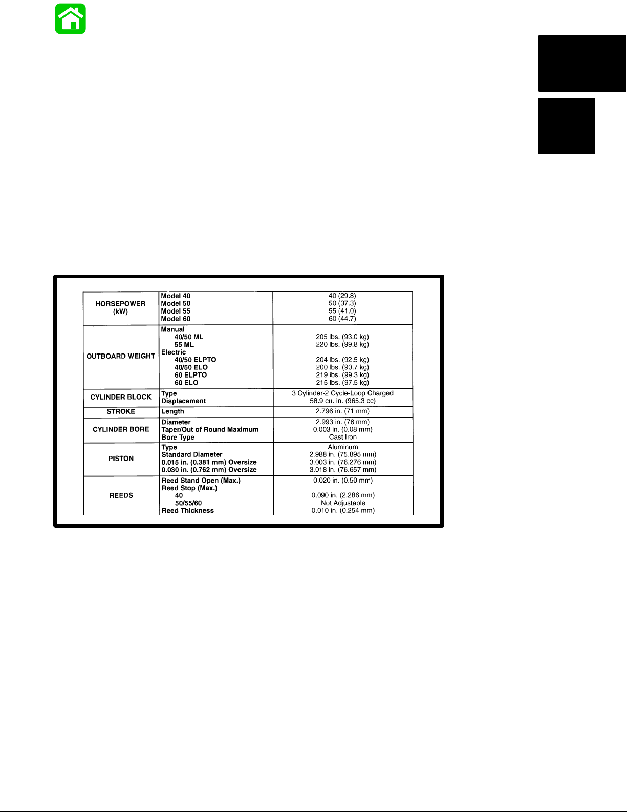
Specifications
Models 40/50/55/60
HORSEPOWER
(kW)
OUTBOARD WEIGHT
CYLINDER BLOCK
STROKE Length 2.796 in. (71 mm)
CYLINDER BORE
PISTON
Model 40
Model 50
Model 55
Model 60
Manual
40/50 ML
55 ML
Electric
40/50 ELPTO
40/50 ELO
60 ELPTO
60 ELO
Type
Displacement
Diameter
Taper/Out of Round Maximum
Bore Type
Type
Standard Diameter
0.015 in. (0.381 mm) Oversize
0.030 in. (0.762 mm) Oversize
40 (29.8)
50 (37.3)
55 (41.0)
60 (44.7)
205 lbs. (93.0 kg)
220 lbs. (99.8 kg)
204 lbs. (92.5 kg)
200 lbs. (90.7 kg)
219 lbs. (99.3 kg)
215 lbs. (97.5 kg)
3 Cylinder-2 Cycle-Loop Charged
59 cu. in. (967 cc)
2.993 in. (76 mm)
0.003 in. (0.08 mm)
Cast Iron
Aluminum
2.988 in. (75.895 mm)
3.003 in. (76.276 mm)
3.018 in. (76.657 mm)
REEDS
FUEL SYSTEM
Reed Stand Open (Max.)
Reed Stop (Max.)
40
50/55/60
Reed Thickness
Recommended Gasoline
Recommended Oil
Break-in Gasoline/Oil Ratio
Manual Start Models
Electric Start Models
After Break-in Gasoline/Oil Ratio
Manual Start Models
Electric Start Models
Fuel Pressure
@ Idle
@ W.O.T.
0.020 in. (0.50 mm)
0.090 in. (2.286 mm)
Not Adjustable
0.010 in. (0.254 mm)
Unleaded-87 Octane Minimum
Quicksilver TC-WII or TC-W3
2 Cycle Outboard Oil
Pre-mixed Gasoline and Oil 25:1
50:1 (In Fuel Tank)
Pre-mixed Gasoline and Oil 50:1
Straight Gasoline
3.5 PSI (24 kPa)
6.0 PSI (41 kPa)
90-852572R1 JANUARY 1998 IMPORTANT INFORMATION - 1A-1
Page 8

GEAR HOUSING
40/50
Gear Ratio
Gearcase Capacity
Lubricant Type
Forward Gear
Number of Teeth
Pinion Gear
Number of Teeth
Pinion Height
Forward Gear Backlash
Water Pressure
@ Idle
@ W.O.T.
Pressure Test
55/60
Gear Ratio
Gearcase Capacity
Lubricant Type
Forward Gear
Number of Teeth
Pinion Gear
Number of Teeth
Pinion Height
Forward Gear Backlash
Water Pressure
@ Idle
@ W.O.T.
Pressure Test
60 Bigfoot
Gear Ratio
Gearcase Capacity
Lubricant Type
Forward Gear
Number of Teeth
Pinion Gear
Number of Teeth
Pinion Height
Forward Gear Backlash
Water Pressure
@ Idle
@ W.O.T.
Pressure Test
1.83:1
14.9 fl. oz. (440 mL)
Quicksilver Gear Lube-Premium Blend
22 Spiral/Bevel
12 Spiral/Bevel
0.025 in. (0.64 mm)
No Adjustment
0.5-1.5 PSI (3-10 kPa)
5.0–7.0 PSI (35-48 kPa)
10-12 PSI (69-83 kPa)
for 5 Minutes
1.64:1
11.5 fl. oz. (340 mL)
Quicksilver Gear Lube-Premium Blend
23
14
0.025 in. (0.64 mm)
Pinion Gear Locating Tool
(91-817008A2)
0.013-0.019 in. (0.33-0.48 mm)
1–3 PSI (7-20 kPa)
7–12 PSI (48-83 kPa)
10-12 PSI (69-83 kPa)
for 5 Minutes
2.3:1
22.5 fl. oz. (655 mL)
Quicksilver Gear Lube-Premium Blend
30
13
0.025 in. (0.64 mm)
0.012 in.-0.019 in. (0.30 mm-0.48 mm)
10-15 PSI (69-103 kPa) @ 5250 RPM
2-7 PSI (14–48 kPa)
10-15 PSI (69-104 kPa)
10-12 PSI (69-83 kPa)
for 5 Minutes
1A-2 - IMPORTANT INFORMATION 90-852572R1 JANUARY 1998
Page 9

STARTING SYSTEM
IGNITION SYSTEM
CHARGING SYSTEM
Manual Start
Electric Start
Starter Draw (Under Load)
Battery Rating
Type
Spark Plug Type
Spark Plug Gap
Firing Order
Alternator Output
Electric Models
Manual Models (Not Regulated)
Recoil Starter
125 Amperes
Min. Reserve Cap. Rating of 100
Min. and CCA of 350 Amperes
Capacitor Discharge
NGK BP8H-N-10
*NGK BPZ8H-N-10
0.040 in. (1.0mm)
1-2-3
Single Phase (12 Pole)
16 Amperes @ 3000 RPM
9 Amperes @ 3000 RPM
7 Amperes @ 3000 RPM
CARBURETOR
OIL
INJECTION
TIMING
Idle RPM
Wide Open Throttle (W.O.T.) RPM
Idle Mixture Screw Adjustment
Preset (Turns Out)
Float Adjustment
Float Level
Main Jet
Model 40 (WME-53, 69)
Model 50 (WME-68)
Model 55 (WME-57)
Model 60 (WME-58)
Recommended Oil
Oil Tank Capacity/Approx. Time
Reserve Capacity/Approx. Time
Oil Output With Engine RPM of 1500
and Oil Pump @ W.O.T.
Model 40
Model 50/60
Idle
Maximum Timing
@ Cranking Speed
-Model 40/50/60
-Model 55/60 Seapro-Marathon
@ 5000 RPM
– Model 40/50/60
– Model 55/60 Seapro-Marathon
675 ± 25
5000-5500
1
/
±1/
1
4
4
9
/16 in. (14 mm)
0.044 in.
0.052 in.
0.058 in.
0.060 in.
Quicksilver TC-WII or TC-W3
2 Cycle Outboard Oil
3.0 qts. (2.8 L) 7 hours
14.5 fl. oz. (0.43 L)
1
/2 hour
15.0 ± 3.0 cc of oil in 10 minutes
22.0 ± 3.0 cc of oil in 10 minutes
T.D.C. ± 2°
24° B.T.D.C.
18° B.T.D.C.
22° B.T.D.C.
16° B.T.D.C.
Temperature
TEMPERATURE
SWITCH
Normal
190°F ± 8° (88°C ± 4°C)
170°F ± 8° (77°C ± 4°C)
*Suppressor (resistor) spark plug
90-852572R1 JANUARY 1998 IMPORTANT INFORMATION - 1A-3
Open - No Continuity
Closed - Full Continuity
Open - No Continuity
Page 10

Propeller Information Charts
Mercury/Mariner 40 HP (3 Cyl.)
Wide Open Throttle RPM: 5000-5500
Recommended Transom Heights : 15”, 20”
Right Hand Rotation Standard
Gear Reduction : 1.83:1
Approx.
No. of
Diameter
10” 19” 3 Alum Up to 900 Up to 14’ 41-49 48-73146A40
10” 17” 3 Alum Up to 900 Up to 14’ 35-43 48-73144A40
10” 16” 3 SS Up to 1200 Up to 15’ 32-40 48-91818A5
10” 16” 3 Alum Up to 1200 Up to 15’ 32-40 48-73142A40
10-1/8” 15” 3 SS 1000-1500 13-15’ 28-37 48-855862A5
10-1/8” 15” 3 Alum 1000-1500 13-15’ 28-37 48-73140A40
10-3/8” 14” 3 Alum 1100-1700 14-16’ 25-34 48-816706A40
10-1/4” 14” 3 SS 1100-1700 14-16’ 25-34 48-855860A5
10-1/4” 14” 3 Alum 1100-1700 14-16’ 25-34 48-73138A40
10-1/2” 13” 3 Alum 1300-2100 14-17’ 21-31 48-816704A40
10-3/8” 13” 3 SS 1300-2100 14-17’ 21-31 48-855858A5
10-3/8” 13” 3 Alum 1300-2100 14-17’ 21-31 48-73136A40
10-3/4” 12” 3 Alum 1500-2500 15-19’ 18-27 48-816702A40
10-5/8” 12” 3 SS 1500-2500 15-19’ 18-27 48-855856A5
10-5/8” 12” 3 Alum 1500-2500 15-19’ 18-27 48-73134A40
Pitch
Blades
Material
Gross Boat
Wgt. (lbs)
Approx.
Boat
Length
Speed
Range
(mph)
Propeller
Part Number
10-7/8” 11” 3 Alum 1800-3500 16-21’ 14-24 48-85632A40
11-1/4” 10” 3 Alum 2000+ 17’+ 11-21 48-73132A40
11-5/8” 11” 3 SS 1800-3500 16-21’ 14-24 48-823478A5
11-5/8” 10-1/2” 3 Alum 2000+ 17’+ 13-23 48-827312A10
12-1/4” 9” 3 Alum 2500+ 18’+ 8-17 48-87818A10
12-1/4” 9” 3 SS 2500+ 18’+ 8-17 48-97868A10
12-1/2” 8” 3 Alum 3000+ 20’+ 1-14 48-42738A10
1A-4 - IMPORTANT INFORMATION 90-852572R1 JANUARY 1998
Page 11

Mercury/Mariner 50 HP (3 Cyl.)
Wide Open Throttle RPM: 5000-5500
Recommended Transom Heights : 15”, 20”, 22-1/2”
Right Hand Rotation Standard
Gear Reduction : 1.83:1
Diameter
Pitch
No. of
Blades
Material
Approx.
Gross Boat
Wgt. (lbs)
Approx.
Boat
Length
Speed
Range
(mph)
Propeller
Part Number
10” 19” 3 Alum Up to 1100 Up to 14’ 41-49 48-73146A40
10” 17” 3 Alum Up to 1400 Up to 14’ 35-43 48-73144A40
10” 16” 3 SS 1200-1500 Up to 15’ 32-40 48-91818A5
10” 16” 3 Alum 1200-1500 Up to 15’ 32-40 48-73142A40
10-1/8” 15” 3 SS 1300-1800 13-15’ 28-37 48-855862A5
10-1/8” 15” 3 Alum 1300-1800 13-15’ 28-37 48-73140A40
10-3/8” 14” 3 Alum 1400-2100 14-16’ 25-34 48-816706A40
10-1/4” 14” 3 SS 1400-2100 14-16’ 25-34 48-855860A5
10-1/4” 14” 3 Alum 1400-2100 14-16’ 25-34 48-73138A40
10-1/2” 13” 3 Alum 1600-2600 14-17’ 21-31 48-816704A40
10-3/8” 13” 3 SS 1600-2600 14-17’ 21-31 48-855858A5
10-3/8” 13” 3 Alum 1600-2600 14-17’ 21-31 48-73136A40
10-3/4” 12” 3 Alum 1900-3200 15-19’ 18-27 48-816702A40
10-5/8” 12” 3 SS 1900-3200 15-19’ 18-27 48-855856A5
10-5/8” 12” 3 Alum 1900-3200 15-19’ 18-27 48-73134A40
10-7/8” 11” 3 Alum 2200-4300 16-21’ 14-24 48-85632A40
11-1/4” 10” 3 Alum 2500+ 17’+ 11-21 48-73132A40
11-5/8” 11” 3 SS 2200-4300 16-21’ 14-24 48-823478A5
11-5/8” 10-1/2” 3 Alum 2200+ 17’+ 13-23 48-827312A10
12-1/4” 9” 3 Alum 3000+ 18’+ 8-17 48-87818A10
12-1/4” 9” 3 SS 3000+ 18’+ 8-17 48-97868A10
12-1/2” 8” 3 Alum 3500+ 20’+ 1-14 48-42738A10
90-852572R1 JANUARY 1998 IMPORTANT INFORMATION - 1A-5
Page 12

Mercury/Mariner 55 HP (3 Cyl.)
Wide Open Throttle RPM: 5000-5500
Recommended Transom Heights : 16-1/2”, 21”, 23-1/2”
Right Hand Rotation Standard
Gear Reduction : 2.3:1
Diameter
Pitch
No. of
Blades
Material
Approx.
Gross Boat
Wgt. (lbs)
Approx.
Boat
Length
Speed
Range
(mph)
Propeller
Part Number
12-3/4” 26” 5 SS Up to 800 Up to 15’ 48-54 48-815748A45
13-1/2” 26” 3 SS Up to 800 Up to 15’ 48-54 48-16996A30
12-3/4” 24” 5 SS Up to1000 Up to 15’ 46-52 48-815746A45
13-1/2” 24” 3 SS Up to 1000 Up to 15’ 46-52 48-16994A30
12-1/2” 23” 3 Alum 700-1100 Up to 15’ 45-51 48-77350A45
12-3/4” 22” 5 SS 700-1100 Up to 15’ 43-49 48-815744A45
13-1/2” 22” 3 SS 700-1100 Up to 15’ 43-59 48-16992A30
12-3/4” 21” 3 Alum 800-1200 13-16’ 40-47 48-77348A45
12-3/4” 20” 5 SS 800-1200 13-16’ 38-45 48-816612A45
13-1/2” 20” 3 SS 800-1200 13-17’ 38-45 48-16990A30
13” 19” 3 Alum 1000-1400 14-17’ 35-42 48-77346A45
13” 18” 3 SS 1000-1400 14-17’ 33-40 48-16988A30
13-1/4” 17” 3 Alum 1200-1700 15-18’ 31-38 48-77344A45
13-1/8” 16” 3 SS 1200-1700 15-18’ 29-36 48-16986A30
13-3/4” 15” 3 Alum 1500-2100 16-19’ 26-33 48-77342A45
13-3/8” 14” 3 SS 1500-2100 16-19’ 23-31 48-17314A30
14” 13” 3 Alum 1900-2500 17’+ 20-28 48-77340A45
14” 12” 3 SS 1900-2500 17’+ 17-26 48-17312A30
14” 11” 3 Alum 2200+ 18’+ 1-22 48-77338A45
14” 10” 3 SS 2400+ 19’+ 1-20 48-17310A30
1A-6 - IMPORTANT INFORMATION 90-852572R1 JANUARY 1998
Page 13

Mercury/Mariner 60 HP (3 Cyl.)
Wide Open Throttle RPM: 5000-5500
Recommended Transom Heights : 15”, 20”
Right Hand Rotation Standard
Gear Reduction : 1.64:1
Diameter
Pitch
No. of
Blades
Material
Approx.
Gross Boat
Wgt. (lbs)
Approx.
Boat
Length
Speed
Range
(mph)
Propeller
Part Number
10” 19” 3 Alum Up to 800 Up to 14’ 48-55 48-73146A40
10” 17” 3 Alum Up to 1000 Up to 15’ 44-51 48-73144A40
10” 16” 3 SS 700-1100 Up to 15’ 41-48 48-91818A5
10” 16” 3 Alum 700-1100 Up to 15’ 41-48 48-73142A40
10-1/8” 15” 3 SS 800-1200 13-15’ 38-45 48-855862A5
10-1/8” 15” 3 Alum 800-1200 13-15’ 38-45 48-73140A40
10-1/4” 14” 3 SS 900-1500 14-16’ 35-41 48-816706A40
10-3/8” 14” 3 Alum 900-1500 14-16’ 35-41 48-855860A5
10-3/8” 13” 3 SS 1200-1800 15-17’ 32-38 48-73138A40
10-1/2” 13” 3 Alum 1200-1800 15-17’ 32-38 48-816704A40
10-5/8” 12” 3 SS 1500-2100 16-18’ 28-34 48-855858A5
10-3/4” 12” 3 Alum 1500-2100 16-18’ 28-34 48-73136A40
10-7/8” 11” 3 Alum 1800-2400 16-18’ 24-30 48-816702A40
11-5/8” 11” 3 SS Workboat 16’+ 24-30 48-855856A5
12” 10-1/2” 3 Alum 2000-2600 17’+ 22-28 48-73134A40
11-5/8” 10-1/2” 3 Alum 2000-2600 17’+ 22-28 48-85632A40
11-1/4” 10” 3 Alum 2100-2600 17’+ 20-26 48-73132A40
12-1/4” 9” 3 SS 2400+ 18’+ 14-22 48-823478A5
12-1/4” 9” 3 Alum 2400+ 18’+ 14-22 48-827312A10
12-1/2” 8” 3 Alum 2800+ 19’+ 1-18 48-87818A10
90-852572R1 JANUARY 1998 IMPORTANT INFORMATION - 1A-7
Page 14

Mercury/Mariner 60 HP (3 Cyl.) Bigfoot
Wide Open Throttle RPM: 5000-5500
Recommended Transom Heights : 15”, 20”, 22-1/2”
Right Hand Rotation Standard
Gear Reduction : 2.31:1
Diameter
Pitch
No. of
Blades
Material
Approx.
Gross Boat
Wgt. (lbs)
Approx.
Boat
Length
Speed
Range
(mph)
Propeller
Part Number
13” 18” 3 SS Up to 1100 Up to 14’ 41-49 48-16988A45
13-1/4” 17” 3 Alum Up to 1400 Up to 14’ 35-43 48-77344A45
13-1/8” 16” 3 SS 1200-1500 Up to 15’ 32-40 48-16986A45
13-3/4” 15” 3 Alum 1200-1500 Up to 15’ 32-40 48-77342A45
13-3/8” 14” 3 SS 1300-1800 13-15’ 28-37 48-17314A45
14” 13” 3 Alum 1300-1800 13-15’ 28-37 48-77340A45
14” 12” 3 SS 1400-2100 14-16’ 25-34 48-17312A45
14” 11” 3 Alum 1400-2100 14-16’ 25-34 48-77338A45
14” 10” 3 Alum 1400-2100 14-16’ 25-34 48-854342A45
14” 9” 3 Alum 1600-2600 14-17’ 21-31 48-854340A45
1A-8 - IMPORTANT INFORMATION 90-852572R1 JANUARY 1998
Page 15
IMPORTANT
INFORMATION
1
B
MAINTENANCE
Page 16

Table of Contents
Specifications 1B-1. . . . . . . . . . . . . . . . . . . . . . . . . .
Gear Case Lubricant Capacity 1B-1. . . . . . . . .
Special Tools 1B-1. . . . . . . . . . . . . . . . . . . . . . . . . .
Quicksilver Lubricant/Sealant 1B-1. . . . . . . . . . . .
Inspection and Maintenance Schedule 1B-2. . . .
Before Each Use 1B-2. . . . . . . . . . . . . . . . . . . .
After Each Use 1B-2. . . . . . . . . . . . . . . . . . . . . .
Every 100 Hours of Use or Once Yearly,
Whichever Occurs First 1B-2. . . . . . . . . . . . . . .
Every 300 Hours of Use or Three Years 1B-2
Before Periods of Storage 1B-2. . . . . . . . . . . .
Flushing The Cooling System 1B-3. . . . . . . . . . . .
Fuel System 1B-3. . . . . . . . . . . . . . . . . . . . . . . . . . .
Corrosion Control Anode 1B-4. . . . . . . . . . . . . . . .
Lubrication Points 1B-5. . . . . . . . . . . . . . . . . . . . . .
Checking Power Trim Fluid 1B-7. . . . . . . . . . . . . .
60 HP 1B-7. . . . . . . . . . . . . . . . . . . . . . . . . . . . . .
40/50 HP 1B-7. . . . . . . . . . . . . . . . . . . . . . . . . . .
Gear Case Lubrication 1B-8. . . . . . . . . . . . . . . . . .
Draining Gear Case 1B-8. . . . . . . . . . . . . . . . . .
Checking Lubricant Level and Filling
Gear Case 1B-9. . . . . . . . . . . . . . . . . . . . . . . . . .
Storage Preparations 1B-9. . . . . . . . . . . . . . . . . . .
Protecting External Outboard
Components 1B-9. . . . . . . . . . . . . . . . . . . . . . . .
Protecting Internal Engine Components 1B-9
Gear Case 1B-10. . . . . . . . . . . . . . . . . . . . . . . . . .
Positioning Outboard for Storage 1B-10. . . . . .
Battery Storage 1B-10. . . . . . . . . . . . . . . . . . . . .
Page
1B-0- IMPORTANT INFORMATION 90-852572R1 JANUARY 1998
Page 17
Specifications
Gear Case Lubricant Capacity
Gear Case Ratio Capacity
2. Quicksilver Anti-Corrosion Grease
P/N 92-78376A6
1.83:1
1.64 :1
2.3:1
14.9 fl. oz. (440 mL)
11.5 fl. oz. (340 mL)
22.5 fl. oz. (655 mL)
Special Tools
1. Quicksilver Flushing Attachment (44357A2)
3. 2-4-C Marine Lubricant with Teflon
P/N 92-825407A12
4. SAE 30W Motor Oil - Obtain Locally
50551
Quicksilver
Lubricant/Sealant
1. Gear Lube-Premium Blend P/N 92-19007A24
30W
90-852572R1 JANUARY 1998 IMPORTANT INFORMATION - 1B-1
Page 18

Inspection and Maintenance
Schedule
Before Each Use
1. Check that lanyard stop switch stops the engine.
2. Visually inspect the fuel system for deterioration
or leaks.
3. Check outboard for tightness on transom.
4. Check steering system for binding or loose components.
5. Remote Control Models – Visually check steering
link rod fasteners for proper tightness.
6. Check propeller blades for damage.
Every 100 Hours of Use or Once
Yearly, Whichever Occurs First
1. Lubricate all lubrication points. Lubricate more
frequently when used in salt water.
2. Inspect and clean spark plugs.
3. Check engine fuel filter for contaminants.
4. Adjust carburetor(s) (if required).
5. Check engine timing setup.∗
6. Check corrosion control anodes. Check more frequently when used in salt water.
7. Drain and replace gear case lubricant.
8. Lubricate splines on the drive shaft.
9. Check power trim fluid.
10. Inspect battery.
∗
After Each Use
1. Flush out the outboard cooling system if operating in salt or polluted water.
2. Wash off all salt deposits and flush out the exhaust outlet of the propeller and gear case with
fresh water if operating in salt water.
11. Check control cable adjustments.
12. Remove engine deposits with Quicksilver Power
Tune Engine Cleaner.
13. Check tightness of bolts, nuts, and other fasteners.
These items should be serviced by an authorized
*
dealer.
∗
Every 300 Hours of Use or Three
Years
1. Replace water pump impeller (more often if overheating occurs or reduced water pressure is
noted).
Before Periods of Storage
Refer to Storage Procedure.
1B-2- IMPORTANT INFORMATION 90-852572R1 JANUARY 1998
Page 19
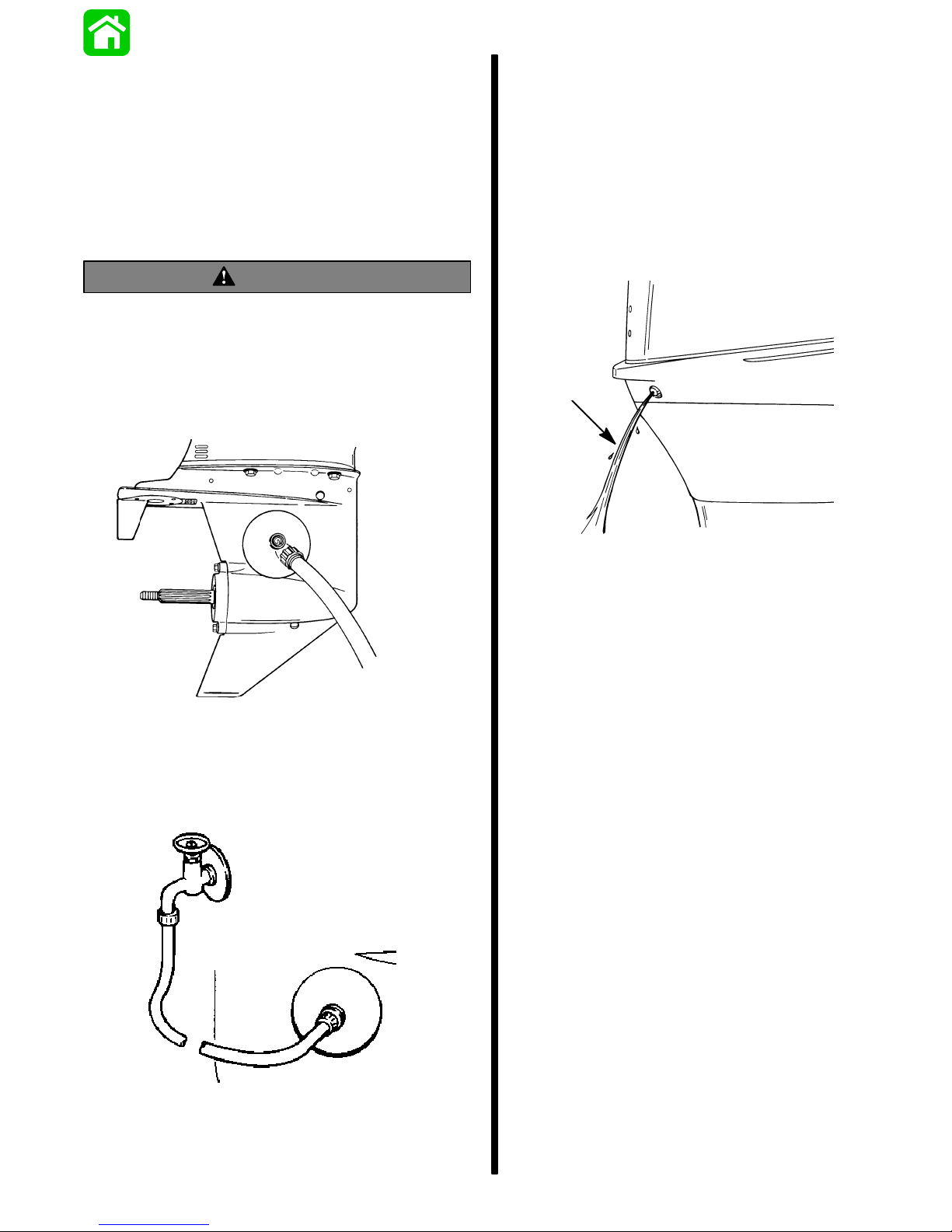
Flushing The Cooling
System
Flush the internal water passages of the outboard
with fresh water after each use in salt, polluted, or
muddy water. This will help prevent a buildup of deposits from clogging the internal water passages.
Use a Quicksilver accessory (or equivalent) flushing
attachment.
W ARNING
To avoid possible injury when flushing, remove
the propeller. Refer to Propeller Replacement.
1. Remove propeller (refer to Propeller Replacement). Install the flushing attachment so the rubber cups fit tightly over the cooling water intake
holes.
3. Start the engine and run it at idle speed in neutral
shift position.
4. Adjust water flow (if necessary) so excess water
continues leaking out from around the rubber
cups to ensure the engine is receiving an adequate supply of cooling water.
5. Check for a steady stream of water flowing out of
the water pump indicator hole. Continue flushing
the outboard for 3 to 5 minutes, carefully monitoring water supply at all times.
2. Attach a water hose to the flushing attachment.
Turn on the water and adjust the flow so water is
leaking around the rubber cups to ensure the engine receives an adequate supply of cooling water.
6. Stop the engine, turn off the water, and remove
the flushing attachment. Reinstall the propeller.
Fuel System
IMPORTANT: Gasoline containing alcohol (ethanol or methanol) can cause a formation of acid
during storage and can damage the fuel system.
If the gasoline being used contains alcohol, it is
advisable to drain as much of the remaining gasoline as possible from the fuel tank, remote fuel
line, and engine fuel system.
Fill the fuel system (tank, hoses, fuel pump, and carburetors) with treated (stabilized) fuel to help prevent
formation of varnish and gum. Proceed with following
instructions.
1. Portable Fuel T ank – Pour the required amount of
Quicksilver Gasoline Stabilizer (follow instructions on container) into fuel tank. Tip fuel tank
back and forth to mix stabilizer with the fuel.
2. Permanently Installed Fuel Tank – Pour the required amount of Quicksilver Gasoline Stabilizer
(follow instructions on container) into a separate
container and mix with approximately one quart
(one liter) of gasoline. Pour this mixture into fuel
tank.
90-852572R1 JANUARY 1998 IMPORTANT INFORMATION - 1B-3
Page 20
3. Place the outboard in water or connect flushing
attachment for circulating cooling water. Run the
engine for ten minutes to allow treated fuel to
reach the carburetors.
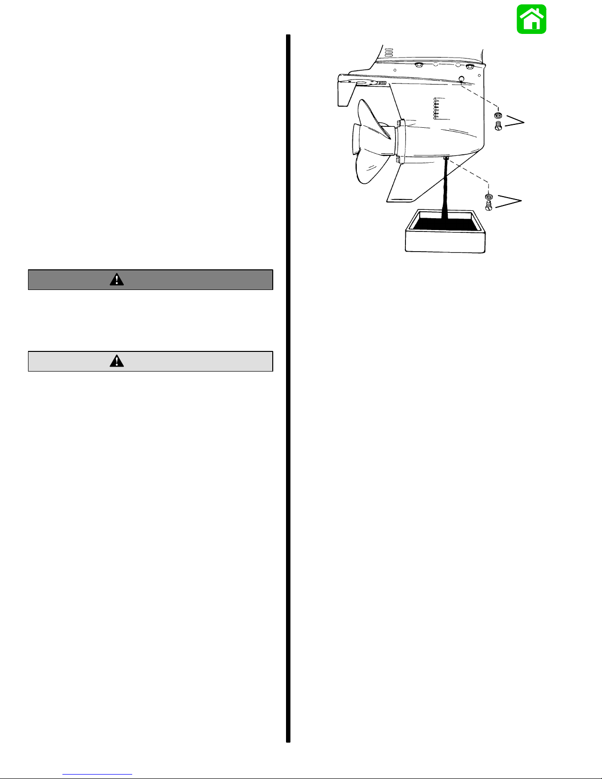
Corrosion Control Anode
1. Y our outboard has two corrosion control anodes.
One of the anodes is the trim tab installed on the
gear case and the other is installed on the bottom
of the transom bracket assembly . An anode helps
protect the outboard against galvanic corrosion
by sacrificing its metal to be slowly eroded instead of the outboard metals.
a
b
a - Trim Tab Anode
b - Transom Bracket Anode
NOTE: Each anode requires periodic inspection especially in salt water which will accelerate the erosion. T o maintain this corrosion protection, always replace the anode before it is completely eroded. Never
paint or apply a protective coating on the anode as
this will reduce effectiveness of the anode.
1B-4- IMPORTANT INFORMATION 90-852572R1 JANUARY 1998
Page 21
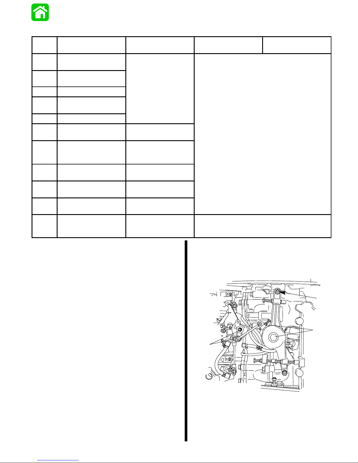
Lubrication Points
ITEM
NO.
1
2
DESCRIPTION
Throttle/Shift linkage
Pivot Points
Shift Handle (Tiller
Handle Models)
3 Swivel Pin
4
Ride Guide Steering
Cable
5 Tilt Tube/Co-Pilot
6
Steering Link Rod
Pivot Points
7 Propellor Shaft
8
9
*
10
◊
Starter Motor Pinion
Gear
Gear Housing Bear-
ing Carrier
Gear Housing
Engine Crankshaft
∆
Splines to Drive Shaft
Splines
TYPE OF
LUBRICANT
Quicksilver 2-4-C
Marine Lubricant
100 Hours of Use or
Once Per Season
SAE 30W Motor Oil
Quicksilver Anti-Cor-
rosion Grease or
2-4-C W/Teflon
SAE 30W Motor Oil
Quicksilver Special
Lubricant 101
Quicksilver Gear
Lube
Quicksilver 2-4-C
Marine Lubricant
FRESH WATER
FREQUENCY
SALT WATER
FREQUENCY
100 Hours of Use or Once Per Season
Once Per Season
* Refer to lubrication instructions outlined in “Salt Water Cor-
rosion - Gear Housing Bearing Carrier and Cover Nut”
of this section (see “Table of Contents”).
◊ Refer to “Gear Housing Lubrication” of this section (see
“T able of Contents”).
∆ Refer to “Gear Housing Removal and Installation”.
1
1
90-852572R1 JANUARY 1998 IMPORTANT INFORMATION - 1B-5
1 - Throttle/Shift Linkage Pivot Points
Page 22
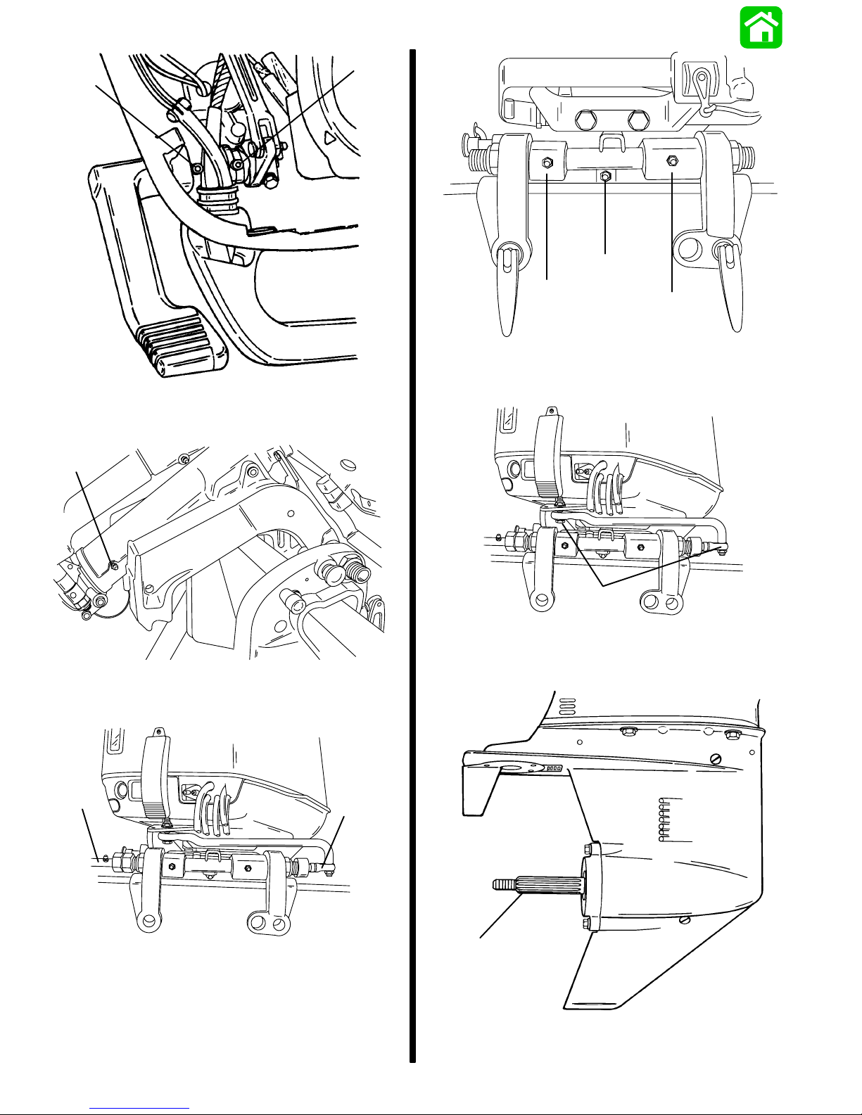
2
2 - Shift Handle (Tiller Handle Models)
3
2
5
5
5 - Tilt Tube/Co-Pilot
5
3 - Swivel Pin
4
4 - Ride Guide Steering Cable
6
6 - Steering Link Rod Pivot Points
4
7
7 - Propellor Shaft
1B-6- IMPORTANT INFORMATION 90-852572R1 JANUARY 1998
Page 23

8
a
50157
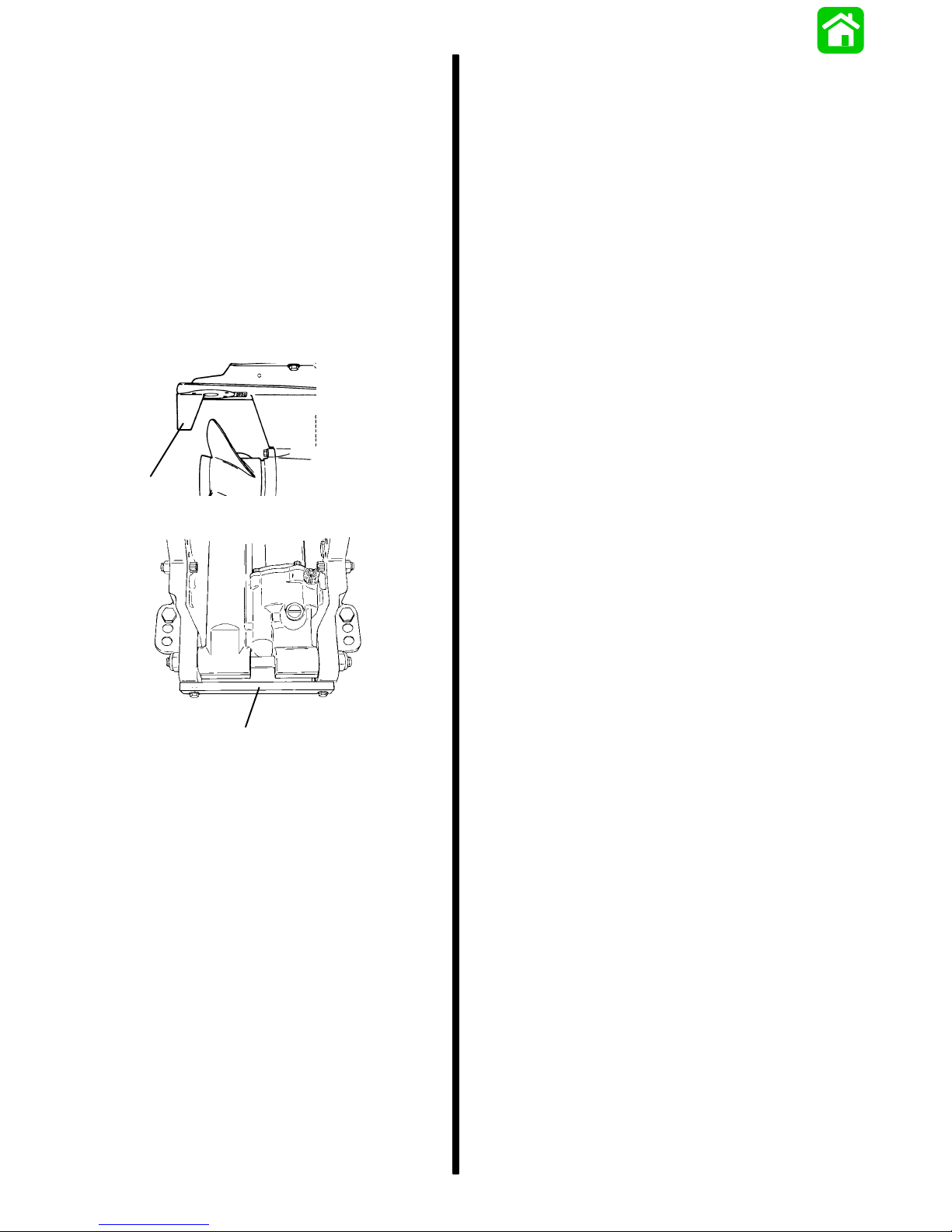
8 - Starter Motor Pinion Gear
9
9 - Gear Housing Bearing Carrier
10-Gear Housing
51118
10
50558
a - Tilt Lock Lever
2. Remove fill screw and check fluid level. Fluid level should be to bottom of threads in fill hole.
3. If necessary, add Quicksilver Power Trim &
Steering Fluid or; Automatic Transmission Fluid
(A TF) Type F, F A or Dexron II fluid to trim system.
4. Reinstall fill screw.
40/50 HP
1. Tilt outboard to the full up position and engage
the tilt support lock.
2. Remove fill cap and check fluid level. The fluid
level should be even with the bottom of the fill
hole. Add Quicksilver Power Trim & Steering
Fluid. If not available, use automotive (A TF) automatic transmission fluid.
Checking Power Trim Fluid
IMPORT ANT : This trim system is pressurized. Remove
fill screw when outboard is trimmed to the full “up” position. Retighten fill screw securely.
60 HP
1. Trim outboard to full “up” position. Engage tilt lock
lever. Trim system fluid can only be checked
when outboard is in this position.
90-852572R1 JANUARY 1998 IMPORTANT INFORMATION - 1B-7
a
b
a - Tilt Support Lock
b - Fill Cap
Page 24
Gear Case Lubrication
When adding or changing gear case lubricant, visually check for the presence of water in the lubricant. If
water is present, it may have settled to the bottom
and will drain out prior to the lubricant, or it may be
mixed with the lubricant, giving it a milky colored appearance. If water is noticed, have the gear case
checked by your dealer.W ater in the lubricant may result in premature bearing failure or, in freezing temperatures, will turn to ice and damage the gear case.
Whenever you remove the fill/drain plug, examine
the magnetic end for metal particles. A small amount
of metal filings or fine metal particles indicates normal gear wear. An excessive amount of metal filings
or larger particles (chips) may indicate abnormal
gear wear and should be checked by an authorized
dealer.
a
b
WARNING
If gear housing is installed on outboard, to avoid
accidental starting, disconnect (and isolate)
spark plug leads from spark plugs before working near the propeller.
CAUTION
Do not use automotive grease in the gear housing. Use only Quicksilver Gear Lube or Quicksilver Super-Duty Lower Unit Lubricant.
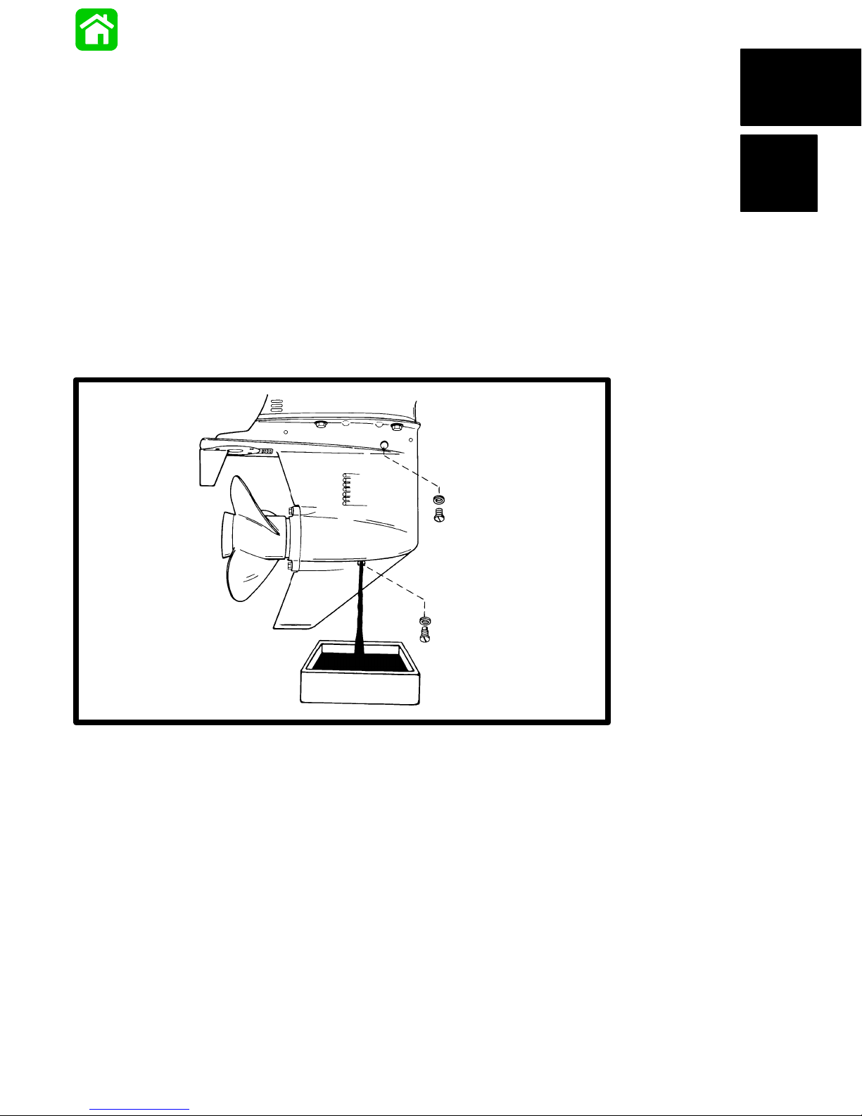
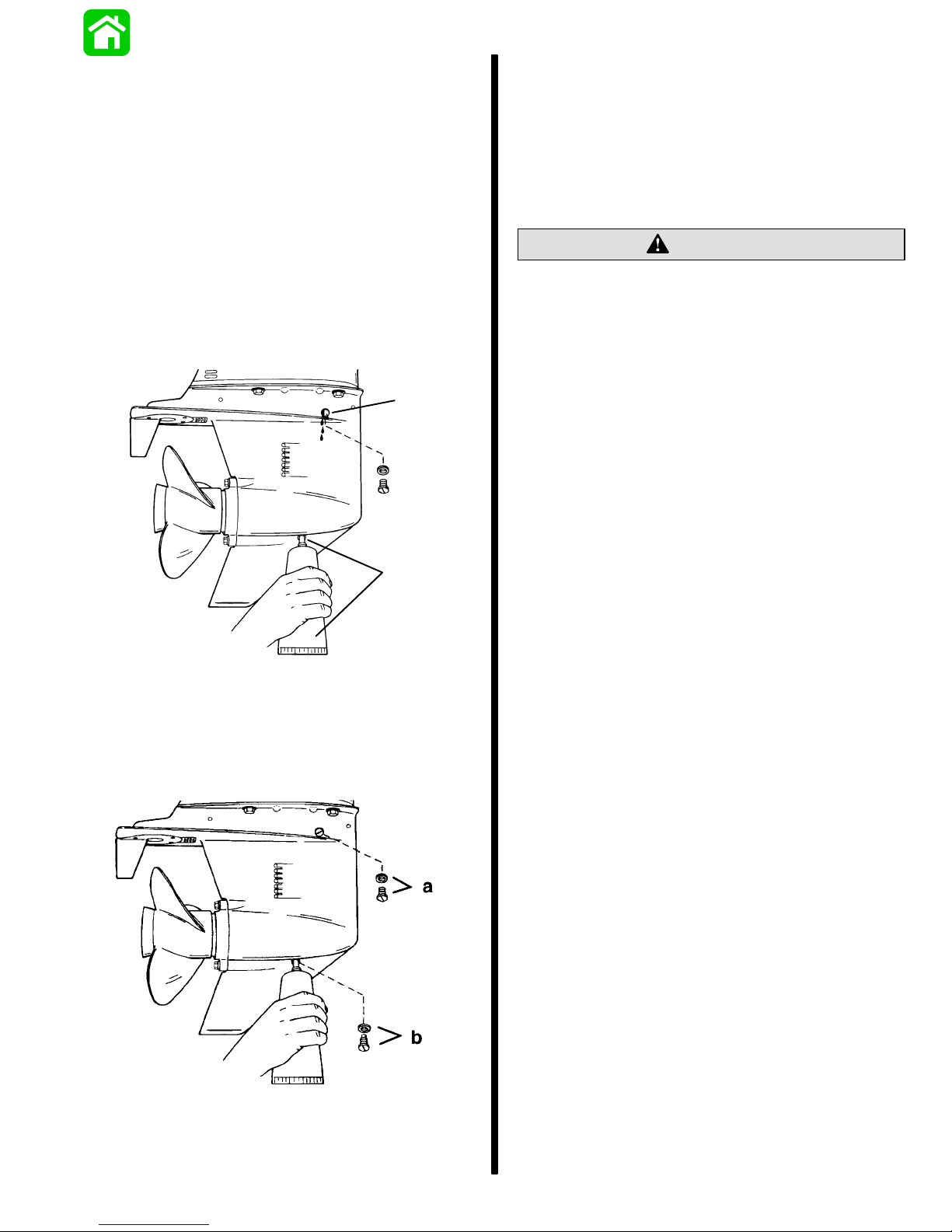
Draining Gear Case
1. Tilt outboard so that lubricant in gear housing will
drain toward front of housing, out fill hole and into
clean container.
IMPORTANT:
for damage. Use new washers as needed.
2. Remove lubricant Fill plug and washer. Note
amount of metal particles on magnetic Fill plug.
Remove all magnetic particles from Fill plug.
Inspect FILL and VENT plug washers
a - Lubricant Vent Plug/Washer
b - Lubricant Fill Plug/Washer
4. Inspect gear lubricant for metal particles (lubricant will have a “metal flake” appearance). Presence of fine metal particles (resembling powder)
on the magnetic fill plug indicates normal wear.
The presence of metal chips on the magnetic fill
plug indicates the need for gear housing disassembly and components inspection.
5. Note color of gear lubricant. White or cream color
indicates presence of water in lubricant. Gear lubricant which has been drained from a gear housing recently in operation, will have a yellowish color due to lubricant agitation/aeration. This is
normal and should not be confused with the presence of water.
6. Presence of water in gear lubricant indicates the
need for disassembly and inspection of oil seals,
seal surfaces, o-rings, water pump gaskets, as
well as, gear housing components for damage.
3. Remove Vent plug and washer and allow all lubricant to drain.
1B-8- IMPORTANT INFORMATION 90-852572R1 JANUARY 1998
Page 25
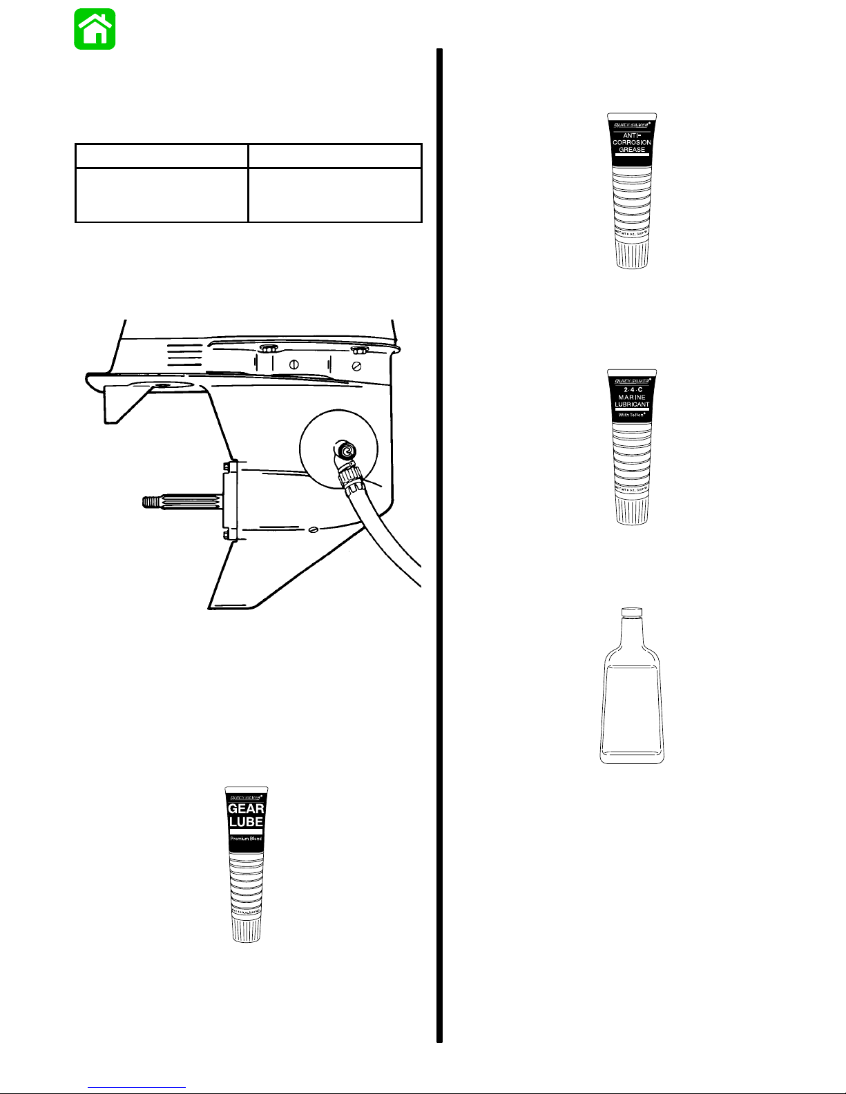
Checking Lubricant Level and Filling
Gear Case
IMPORTANT: Never add lubricant to gear housing
without first removing VENT plug, as trapped air
will prevent housing from being filled. Fill gear
housing only when outboard is in operating position.
NOTE:
lubricant capacity.
Refer to “Specifications,” for gear housing
Storage Preparations
The major consideration in preparing your outboard
for storage is to protect it from rust, corrosion, and
damage caused by freezing of trapped water.
The following storage procedures should be followed
to prepare your outboard for out-of-season storage
or prolonged storage (two months or longer).
CAUTION
1. With outboard in operating position, insert lubricant tube into fill hole.
2. Fill gear housing until excess lubricant flows from
VENT hole.
b
a
a - Lubricant/Fill Hole
b - Vent Hole
Never start or run your outboard (even momentarily) without water circulating through all the
cooling water intake holes in the gear case to prevent damage to the water pump (running dry) or
overheating of the engine.
Protecting External Outboard
Components
1. Lubricate all outboard components listed in the
Inspection and Maintenance Schedule.
2. Touch up any paint nicks. See your dealer for
touch-up paint.
3. Spray Quicksilver Corrosion Guard on engine exterior, electrical components, and other metal
surfaces (except corrosion control anodes).
Protecting Internal Engine
Components
3. Install VENT plug and washer.
4. Install FILL plug and washer.
a - Vent Plug/Washer
b - Fill Plug/Washer
NOTE: Before performing the following steps, make
sure the fuel system has been prepared for storage.
Refer to Fuel System.
1. Place the outboard in water or connect flushing
attachment for circulating cooling water. Start the
engine and let it run in neutral to warm up.
2. With engine running at fast idle, stop the fuel flow
by disconnecting the remote fuel line. When engine begins to stall, quickly spray Quicksilver
Storage Seal into carburetor until engine stops
from lack of fuel.
3. Remove the spark plugs and inject a five second
spray of Quicksilver Storage Seal around the inside of each cylinder.
4. Rotate the flywheel manually several times to
distribute the storage seal in the cylinders. Reinstall spark plugs.
90-852572R1 JANUARY 1998 IMPORTANT INFORMATION - 1B-9
Page 26

Gear Case
1. Drain and refill the gear case lubricant (refer to
maintenance procedure).
Positioning Outboard for Storage
1. Store outboard in an upright (vertical) position to
allow water to drain out of outboard.
CAUTION
If outboard is stored tilted up in freezing temperature, trapped cooling water or rain water that may
have entered the propeller exhaust outlet in the
gear case could freeze and cause damage to the
outboard.
Battery Storage
1. Follow the battery manufacturers instructions for
storage and recharging.
2. Remove the battery from the boat and check water level. Recharge if necessary.
3. Store the battery in a cool, dry place.
4. Periodically check the water level and recharge
the battery during storage.
1B-10- IMPORTANT INFORMATION 90-852572R1 JANUARY 1998
Page 27
IMPORTANT
INFORMATION
1
C
GENERAL INFORMATION
Page 28

Table of Contents
Serial Number Location 1C-1. . . . . . . . . . . . . . . . .
Conditions Affecting Performance 1C-1. . . . . . . .
Weather 1C-1. . . . . . . . . . . . . . . . . . . . . . . . . . . . .
Boat 1C-2. . . . . . . . . . . . . . . . . . . . . . . . . . . . . . . .
Engine 1C-3. . . . . . . . . . . . . . . . . . . . . . . . . . . . . .
Following Complete Submersion 1C-3. . . . . . . . .
Salt Water Submersion
(Special Instructions) 1C-3. . . . . . . . . . . . . . . . . .
Submerged While Running
(Special Instructions) 1C-3. . . . . . . . . . . . . . . . . .
Submerged Engine (Fresh Water)
(Plus Special Instructions) 1C-4. . . . . . . . . . . . .
Propeller Selection 1C-4. . . . . . . . . . . . . . . . . . . . .
Propeller Removal/Installation 1C-5. . . . . . . . . . .
Removal 1C-5. . . . . . . . . . . . . . . . . . . . . . . . . . . .
Installation 1C-5. . . . . . . . . . . . . . . . . . . . . . . . . . .
Page
1C-0 - IMPORTANT INFORMATION 90-852572R1 JANUARY 1998
Page 29
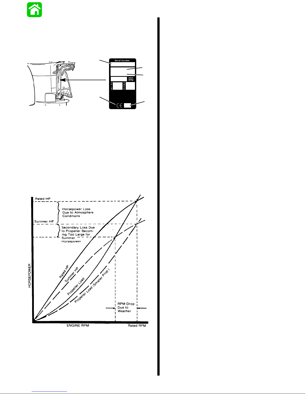
Serial Number Location
The Outboard serial number is located on the lower
starboard side of the engine block. A serial number
is also located on the starboard side of the swivel
bracket.
a
OGXXXXXX
19XX
XXXX
b
c
e
XX
a - Serial Number
b - Model Year
c - Model Description
d - Year Manufactured
e - Certified Europe Insignia
d
Conditions Affecting
Performance
Corporations internationally have settled on adoption of I.S.O. (International Standards Organization)
engine test standards, as set forth in I.S.O. 3046
standardizing the computation of horsepower from
data obtained on the dynamometer, correcting all values to the power that the engine will produce at sea
level, at 30% relative humidity at 77° F (25° C) temperature and a barometric pressure of 29.61 inches
of mercury.
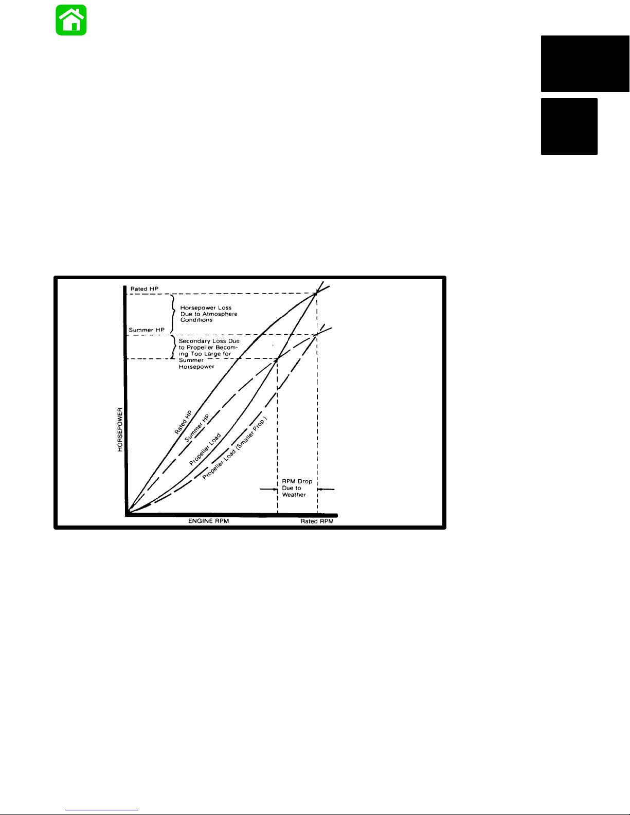
Summer Conditions of high temperature, low barometric pressure and high humidity all combine to reduce the engine power. This, in turn, is reflected in
decreased boat speeds, as much as 2 or 3 miles-perhour (3 or 5 km per-hour) in some cases. (Refer to
previous chart.) Nothing will regain this speed for the
boater, but the coming of cool, dry weather.
In pointing out the practical consequences of weather effects, an engine running on a hot, humid summer
day--may encounter a loss of as much as 14% of the
horsepower it would produce on a dry , brisk spring or
fall day. The horsepower that any internal combustion engine produces, depends upon the density of
the air that it consumes and, in turn, this density is dependent upon the temperature of the air , its barometric pressure and water vapor (or humidity) content.
Weather
It is a known fact that weather conditions exert a profound effect on power output of internal combustion
engines. Therefore, established horsepower ratings
refer to the power that the engine will produce at its
rated RPM under a specific combination of weather
conditions.
Accompanying this weather-inspired loss of power is
a second but more subtle loss. At rigging time in early
spring, the engine was equipped with a propeller that
allowed the engine to turn within its recommended
RPM range at full throttle. With the coming of the
summer weather and the consequent drop in available horsepower, this propeller will, in ef fect, become
too large. Consequently , the engine operates at less
than its recommended RPM.
Due to the horsepower/RPM characteristics of an engine, this will result in further loss of horsepower at
the propeller with another decrease in boat speed.
This secondary loss, however, can be regained by
switching to a smaller pitch propeller that allows the
engine to again run at recommended RPM.
For boaters to realize optimum engine performance
under changing weather conditions, it is essential
that the engine have the proper propeller to allow it
to operate at or near the top end of the recommended
maximum RPM range at wide-open-throttle with a
normal boat load.
Not only does this allow the engine to develop full
power, but equally important is the fact that the engine also will be operating in an RPM range that discourages damaging detonation. This, of course, enhances overall reliability and durability of the engine.
90-852572R1 JANUARY 1998 IMPORTANT INFORMATION - 1C-1
Page 30

Boat
TRIM
WEIGHT DISTRIBUTION
1. Proper positioning of the weight inside the boat
(persons and gear) has a significant effect on the
boat’s performance, for example:
a. Shifting weight to the rear (stern)
(1.)Generally increases top speed.
(2.) If in excess, can cause the boat to por-
poise.
(3.) Can make the bow bounce excessively in
choppy water.
(4.) Will increase the danger of waves splash-
ing into the boat when coming off plane.
b. Shifting weight to the front (bow)
(1.) Improves ease of planing off.
(2.) Generally improves rough water ride.
(3.) If excessive, can make the boat veer left
and right (bow steer).
BOTTOM
For maximum speed, a boat bottom should be
nearly a flat plane where it contacts the water and
particularly straight and smooth in fore-and-aft direction.
1. Hook: Exists when bottom is concave in fore-
and-aft direction when viewed from the side.
When boat is planing, “hook” causes more lift on
bottom near transom and allows bow to drop,
thus greatly increasing wetted surface and reducing boat speed. “Hook” frequently is caused
by supporting boat too far ahead of transom while
hauling on a trailer or during storage.
2. Rocker: The reverse of hook and much less
common. “Rocker” exists if bottom is convex in
fore-and-aft direction when viewed from the side,
and boat has strong tendency to porpoise.
TRIMMING OUTBOARD “OUT” (“UP”)
WARNING
Excessive trim “out” also may reduce the stability of some high speed hulls. T o correct instability at high speed, reduce the power GRADUALLY
and trim the outboard “in” slightly before resuming high speed operation. (Rapid reduction in
power will cause a sudden change of steering
torque and may cause additional momentary
boat instability.)
1. Will lift bow of boat, generally increasing top
speed.
2. Transfers steering torque harder to left on single
outboard installations below 23 in. (584mm) transom height.
3. Increases clearance over submerged objects.
4. In excess, can cause porpoising and/or ventilation.
5. If trimmed out beyond the water pickup, reduced
water supply can cause overheating resulting in
engine damage.
TRIMMING OUTBOARD “IN” (“DOWN”)
WARNING
Excessive speed at minimum trim “in” may
cause undesirable and/or unsafe steering conditions. Each boat should be tested for handling
characteristics after any adjustment is made to
the angle (trim adjustment bolt relocation.)
1. Will help planing off, particularly with a heavy
load.
2. Usually improves ride in choppy water.
3. In excess, can cause boat to veer to the left or
right (bow steer).
3. Surface Roughness: Moss, barnacles, etc., on
boat or corrosion of outboard’s gear housing increase skin friction and causes speed loss. Clean
surfaces when necessary.
4. Transfers steering torque harder to right (or less
to the left) on single outboard installations.
5. Improves planing speed acceleration (by moving
trim adjustment bolt one hole closer to transom).
WATER ABSORPTION
It is imperative that all through hull fasteners be
coated with a quality marine sealer at time of installation. Water intrusion into the transom core and/or inner hull will result in additional boat weight (reduced
boat performance), hull decay and eventual structural failure.
1C-2 - IMPORTANT INFORMATION 90-852572R1 JANUARY 1998
Page 31

CAVITATION
Detonation usually can be prevented if:
Cavitation is caused by water vapor bubbles forming
either from a sharp edge or angle on the gear case
or from an irregularity in the propeller blade itself.
These vapor bubbles flow back and collapse when
striking the surface of the propeller blade resulting in
the erosion of the propeller blade surface. If allowed
to continue, eventual blade failure (breakage) will
occur.
Engine
DETONATION
Detonation in a 2-cycle engine resembles the “pinging” heard in an automobile engine. It can be otherwise described as a tin-like “rattling” or “plinking”
sound.
Detonation is an explosion of an unburned portion of
the fuel/air charge after the spark plug has fired. Detonation creates severe shock waves in the engine,
and these shock waves often find or create a weakness; The dome of a piston, cylinder head/gasket,
piston rings or piston ring lands, piston pin and roller
bearings.
1. The engine is correctly set up.
2. Diligent maintenance is applied to combat the
detonation causes.
51115
Damaged Piston Resulting from Detonation
Following Complete
A few of the most common causes of detonation in a
marine 2-cycle application are as follows:
• Over-advanced ignition timing.
• Use of low octane gasoline.
• Propeller pitch too high (engine RPM below rec-
ommended maximum range).
• Lean fuel mixture at or near wide-open-throttle.
• Spark plugs (heat range too hot - incorrect reach
- cross-firing).
• Inadequate engine cooling (deteriorated cooling
system).
• Combustion chamber/piston deposits (result in
higher compression ratio).
Submersion
Salt Water Submersion (Special
Instructions)
Due to the corrosive effect of salt water on internal
engine components, complete disassembly is necessary before any attempt is made to start the engine.
Submerged While Running (Special
Instructions)
When an engine is submerged while running, the
possibility of internal engine damage is greatly increased. If, after engine is recovered and with spark
plugs removed, engine fails to turn over freely when
turning flywheel, the possibility of internal damage
(bent connecting rod and/or bent crankshaft) exists.
If this is the case, the powerhead must be disassembled.
90-852572R1 JANUARY 1998 IMPORTANT INFORMATION - 1C-3
Page 32

Submerged Engine (Fresh Water)
(Plus Special Instructions)
1. Recover engine as quickly as possible.
2. Remove cowling.
3. Flush exterior of outboard with fresh water to remove mud, weeds, etc. DO NOT attempt to start
engine if sand has entered powerhead, as powerhead will be severely damaged. Disassemble
powerhead if necessary to clean components.
4. Remove spark plugs and get as much water as
possible out of powerhead. Most water can be
eliminated by placing engine in a horizontal position (with spark plug holes down) and rotating flywheel.
5. Pour alcohol into carburetor throats (alcohol will
absorbed water). Again rotate flywheel.
6. Turn engine over and pour alcohol into spark plug
openings and rotate flywheel.
7. Turn engine over (place spark plug openings
down) and pour engine oil into throat of carburetors while rotating flywheel to distribute oil
throughout crankcase.
8. Again turn engine over and pour approximately
one teaspoon of engine oil into each spark plug
opening. Again rotate flywheel to distribute oil in
cylinders.
9. Remove and clean carburetors and fuel pump
assembly.
10. Dry all wiring and electrical components using
compressed air.
1 1. Disassemble the engine starter motor and dry the
brush contacts, armature and other corrodible
parts.
12. Reinstall spark plugs, carburetors and fuel pump.
Propeller Selection
For in-depth information on marine propellers and
boat performance - written by marine engineers - see
your Authorized Dealer for the illustrated “What Y ou
Should Know About Quicksilver Propellers... and
Boat Performance Information” (Part No.
90-86144-92).
For best all around performance from your outboard/
boat combination, select a propeller that allows the
engine to operate in the upper half of the recommended full throttle RPM range with the boat normally loaded (refer to Specifications). This RPM range
allows for better acceleration while maintaining maximum boat speed.
If changing conditions cause the RPM to drop below
the recommended range (such as warmer, more humid weather, operation at higher elevations, increased boat load or a dirty boat bottom/gear case)
a propeller change or cleaning may be required to
maintain performance and ensure the outboard’s durability .
Check full-throttle RPM using an accurate tachometer with the engine trimmed out to a balanced-steering condition (steering effort equal in both directions)
without causing the propeller to “break loose”.
Refer to “Quicksilver Accessory Guide” for a complete list of available propellers.
1. Select a propeller that will allow the engine to op-
erate at or near the top of the recommended full
throttle RPM range (listed in “Specifications,”
preceding) with a normal load. Maximum engine
speed (RPM) for propeller selection exists when
boat speed is maximum and trim is minimum for
that speed. (High RPM, caused by an excessive
trim angle, should not be used in determining correct propeller.) Normally , there is a 150-350 RPM
change between propeller pitches
.
13. Attempt to start engine, using a fresh fuel source.
If engine starts, it should be run for at least one
hour to eliminate any water in engine.
14. If engine fails to start, determine cause (fuel,
electrical or mechanical). Engine should be run
within 2 hours after recovery of outboard from
water, or serious internal damage may occur. If
unable to start engine in this period, disassemble
engine and clean all parts. Apply oil as soon as
possible.
1C-4 - IMPORTANT INFORMATION 90-852572R1 JANUARY 1998
2. If full throttle operation is below the recom-
mended range, the propeller MUST BE changed
to one with a lower pitch to prevent loss of performance and possible engine damage.
Page 33

3. After initial propeller installation, the following
common conditions may require that the propeller be changed to a lower pitch:
a. Warmer weather and great humidity will
cause an RPM loss.
b. Operating in a higher elevation causes an
RPM loss.
c. Operating with a damaged propeller or a dirty
boat bottom or gear housing will cause an
RPM loss.
d. Operation with an increased load (additional
passengers, equipment, pulling skiers, etc.).
Propeller
Removal/Installation
5. Pull propeller straight off shaft. If propeller is
seized to the shaft and cannot be removed, have
the propeller removed by an authorized dealer.
Installation
Removal
1. Shift outboard to neutral (N) position.
2. Remove the spark plug leads to prevent engine
from starting.
3. Straighten the bent tabs on the propeller nut retainer.
4. Place a block of wood between gear case and
propeller to hold propeller and remove propeller
nut.
WARNING
If the propeller shaft is rotated while the engine
is in gear, there is the possibility that the engine
will crank over and start. To prevent this type of
accidental engine starting and possible serious
injury caused from being struck by a rotating propeller, always shift outboard to neutral position
and remove spark plug leads when you are servicing the propeller.
CAUTION
If the propeller moves forward-and-aft on the propeller shaft (is loose), re-tighten the propeller
nut. Operation with a loose propeller could cause
damage to the thrust hub and gear housing during acceleration, deceleration or when shifting
gears.
IMPORTANT: To assure that the propeller remains
secure on the shaft during the season, periodically check propeller shaft nut for tightness.
90-852572R1 JANUARY 1998 IMPORTANT INFORMATION - 1C-5
Page 34

1. To aid in future removal of the propeller, liberally
coat the propeller shaft spline with one of the following Quicksilver lubricants:
• Anti-Corrosion Grease
• 2-4-C Marine Lubricant
2. Place forward thrust hub on propeller shaft.
6. After first use, bend the tab straight, re-tighten
propeller nut and again bend tab washer to secure nut. Check propeller periodically for tightness.
3. Flo-Torque I Drive Hub Propellers
– Install forward thrust hub, propeller, propeller nut retainer
and propeller nut onto the shaft.
c
d
a
b
a - Forward Thrust Hub
b - Propeller
c - Propeller Nut Retainer
d - Propeller Nut
4. Flo-Torque II Drive Hub Propellers – Install forward thrust hub, propeller, replaceable drive
sleeve, rear thrust hub, propeller nut retainer and
propeller nut onto the shaft.
d
e
f
c
a - Forward Thrust Hub
b - Propeller
c - Replaceable Drive Sleeve
d - Rear Thrust Hub
e - Propeller Nut Retainer
f - Propeller Nut
a
b
5. Place propeller nut retainer over pins. Place a
block of wood between gear case and propeller
and tighten propeller nut to 55 lb.ft. (75 N·m),
aligning flat sides of the propeller nut with tabs on
the propeller nut retainer.
a
b
a - Pins
b - Tabs
b
a
1C-6 - IMPORTANT INFORMATION 90-852572R1 JANUARY 1998
Page 35

IMPORTANT
INFORMATION
1
D
OUTBOARD MOTOR INSTALLATION
Page 36

Table of Contents
Lifting Outboard 1D-1. . . . . . . . . . . . . . . . . . . . . . . .
Steering Link Rod 1D-1. . . . . . . . . . . . . . . . . . . . . .
Installing Outboard 40-50 HP 1D-2. . . . . . . . . . . .
40-50 Hp – Non-Thumb Screw Models 1D-2.
40-50 HP – Thumb Screw Models 1D-3. . . . .
Installing Outboard 55-60 HP 1D-4. . . . . . . . . . . .
55-60 HP - Non-Thumb Screw Models 1D-4.
55-60 HP – Thumb Screw Models 1D-5. . . . .
Wiring Harness 1D-6. . . . . . . . . . . . . . . . . . . . . . . .
Battery Cable Connections 1D-6. . . . . . . . . . . . . .
Shift and Throttle Cable
40 and 50 Hp Models 1D-7. . . . . . . . . . . . . . . . . . .
40-50 Hp – Shift Cable Installation 1D-7. . . . .
40-50 Hp – Throttle Cable Installation 1D-8. .
Shift and Throttle Cable
60 HP Models 1D-9. . . . . . . . . . . . . . . . . . . . . . . . .
60 HP – Shift Cable Installation 1D-9. . . . . . . .
60 HP – Throttle Cable Installation 1D-10. . . . .
Trim Tab Adjustment 1D-11. . . . . . . . . . . . . . . . . . . .
Page
1D-0 - IMPORTANT INFORMATION 90-852572R1 JANUARY 1998
Page 37

Lifting Outboard
Steering Link Rod
Electric Start Models – Remove plastic cap from fly-
wheel hub. Thread lifting ring into flywheel a minimum of 5 turns. Replace plastic cap after installation.
Manual Start Models – Use lifting eye.
1. Install steering link rod per illustration.
40-60 HP
60 Hp
f
40-50 Hp
b
c
a
a - Special Bolt (10-90041) Torque to
20 lb. ft.(27.1 N·m)
b - Nylon Insert Locknut (11-34863) Torque to
20 lb. ft.(27.1 N·m)
c - Spacer (12-71970)
d - Flat Washer (2)
e Nylon Insert Locknut (11-34863) Tighten Locknut Until it
Seats, Then Back Nut Off 1/4 Turn
f - Use Correct Hole
d
e
IMPORT ANT: The steering link rod that connects
the steering cable to the engine must be fastened
using special bolt (“a” - Part Number 10-90041)
and self locking nuts (“b” & “e” Part Number
11-34863). These locknuts must never be replaced with common nuts (non-locking) as they
will work loose and vibrate off, freeing the link
rod to disengage.
WARNING
Disengagement of a steering link rod can result
in the boat taking a full, sudden, sharp turn. This
potentially violent action can cause occupants to
be thrown overboard exposing them to serious
injury or death.
90-852572R1 JANUARY 1998 IMPORTANT INFORMATION - 1D-1
Page 38

Installing Outboard 40-50 HP
40-50 Hp – Non-Thumb Screw Models
a
5. Drill four mounting holes using a 17/32 in. (13.5
mm) drill bit.
a - Non-Thumb Screw
2. Center outboard on the transom.
3. Secure outboard to the transom temporarily using C-clamps.
6. Position outboard so the anti-ventilation plate is
within 1 in. (25.4 mm) of the boat bottom.
a
0 - 1 in.
(0 - 25.4mm)
a - Anti-Ventilation Plate
7. Fasten outboard with provided mounting hardware shown. Apply RTV Silicon Sealer to shanks
of bolts (not threads).
85
4. Mark location for four mounting holes.
NOTE: Normally the 4 upper mounting holes marked
c
b
are to be drilled. This allows the outboard to be raised
without re-drilling. Use other holes if necessary to
85
RTV Silicone Sealer (92-91601-1)
avoid obstructions.
a - 1/2 in. (12.7 mm) Diameter Bolt (4)
b - Flat Washer (4)
a
c - Locknut (4)
a
WARNING
a
a - Upper Mounting Holes
1D-2 - IMPORTANT INFORMATION 90-852572R1 JANUARY 1998
a
Before operation, the outboard must be correctly
installed with four mounting bolts shown. Failure
to correctly fasten outboard could result in outboard ejecting off boat transom causing serious
injury, death, or property damage.
a
Page 39

40-50 HP – Thumb Screw Models
a
a - Thumb Screw
NOTE: Quicksilver Accessory Outboard Mounting
Kit (P/N 812432A5) allows for quick removal and
installation of outboard. Refer to installation instructions supplied with the mounting kit before drilling any
holes. Tighten retainer screws into lower mounting
holes when using mounting kit.
WARNING
Outboard must be fastened to boat transom one
of two ways: 1. permanently fastened to transom
with thumb screws and mounting bolts (provided), or 2. secured to the transom using the optional outboard mounting kit (P/N 812432A5).
Should the outboard strike an underwater object
or be steered into a sharp turn, failure to fasten
outboard correctly to the boat transom with
mounting bolts or optional mounting kit could result in outboard ejecting suddenly off boat transom causing serious injury , death, boat damage,
or loss of outboard.
1. Center outboard on the transom.
a
b
a - Accessory Outboard Mounting KIt
b - Retaining Screws
3. T ype 1 Bracket – Drill two 1/2 in. (12.7 mm) holes
through a lower set of mounting holes.
4. T ype 2 Bracket – Drill two 3/8 in. (9.5 mm) holes
through the lower mounting holes.
5. Fasten outboard with provided mounting hardware shown. Apply RTV Silicon Sealer to shanks
of bolts (not threads).
T ype 1 Bracket
T ype 2 Bracket
ee
2. Position outboard so the anti-ventilation plate is
within 1 in. (25.4 mm) of the boat bottom.
0 - 1 in.
(0 - 25.4 mm)
a - Anti-Ventilation Plate
90-852572R1 JANUARY 1998 IMPORTANT INFORMATION - 1D-3
c
85
d
b
d
c
85
a - 1/2 in.(12.7 mm) Diameter Bolt (2)
b - 3/8 in. (9.5 mm) Diameter Bolt (2)
a
c - Flat Washer (2)
d - Locknut (2)
e - Thumb Screws, Tighten Securely
RTV Silicone Sealer (92-91601-1)
a
85
WARNING
DO NOT, under any circumstances, allow the
cupped washers on the ends of the thumb
screws to be closer than 1 in. (25.4 mm) from top
of the boat transom, not shims.
Page 40

Installing Outboard 55-60 HP
55-60 HP - Non-Thumb Screw Models
a
a - Non Thumb Screw
6. Center outboard on the transom.
9. Drill four mounting holes using a 17/32 in. (13.5
mm) drill bit.
10. Position outboard so the anti-ventilation plate is
within 1 in. (25.4 mm) of the boat bottom.
a
0 - 1 in.
(0 - 25.4 mm)
7. Secure outboard to the transom temporarily using C-clamps.
8. Mark location for four mounting holes.
NOTE: Normally the 4 upper mounting holes marked
(a) are to be drilled. This allows the outboard to be
raised without re-drilling. Use other holes if necessary to avoid obstructions.
a
a
a - Anti-Ventilation Plate
11. Fasten outboard with provided mounting hardware shown. Apply RTV Silicon Sealer to shank
of bolts (not threads).
c
b
85
a - 1/2 in. Diameter Bolts (4)
b - Flat Washer (4)
c - Locknut (4)
RTV Silicone Sealer (92-91601-1)
85
a
WARNING
a
a - Upper Mounting Holes
1D-4 - IMPORTANT INFORMATION 90-852572R1 JANUARY 1998
a
Before operation, the outboard must be correctly
installed with four mounting bolts shown. Failure
to correctly fasten outboard could result in outboard ejecting off boat transom causing serious
injury, death, or property damage.
Page 41

55-60 HP – Thumb Screw Models
a
a - Thumb Screw
WARNING
NOTE: Quicksilver Accessory Outboard Mounting
Kit (P/N 812432A4) allows for quick removal and
installation of outboard. Refer to installation instructions supplied with the mounting kit before drilling any
holes.
Outboard must be fastened to boat transom one
of two ways: 1. permanently fastened to transom
with thumb screws, and mounting bolts (provided), or 2. secured to the transom using the optional outboard mounting kit (P/N 812432A4).
Should the outboard strike an underwater object
or be steered into a sharp turn, failure to fasten
outboard correctly to the boat transom with
mounting bolts or optional mounting kit could result in outboard ejecting suddenly off boat transom causing serious injury , death, boat damage,
or loss of outboard.
1. Center outboard on the transom.
a
a - Accessory Outboard Mounting Kit
3. Drill four 1/2 in. (12.7 mm) mounting holes.
4. Fasten outboard with provided mounting hardware shown. Apply RTV Silicon Sealer to shank
of bolt (not thread).
d
85
c
b
a
85
RTV Silicone Sealer (92-91601-1)
2. Position outboard so the anti-ventilation plate is
within 1 in. (25.4 mm) of the boat bottom.
0 - 1 in.
(0 - 25.4 mm)
a - Anti-Ventilation Plate
90-852572R1 JANUARY 1998 IMPORTANT INFORMATION - 1D-5
a - 1/2 in.(12.7 mm) Diameter Bolt (4)
b - Flat Washer (4)
c - Locknut (4)
d - Thumb Screws, Tighten Securely
WARNING
a
DO NOT, under any circumstances, allow the
cupped washers on the ends of the thumb
screws to be closer than 1 inch (25.4 mm) from
top of the boat transom, not shims.
Page 42

Wiring Harness
Battery Cable Connections
IMPORTANT: Warning Horn Requirement – The
remote control or key switch assembly must be
wired with a warning horn. This warning horn is
used with the engine warning system.
1. Route wiring harness into bottom cowl.
40-50 HP
a
60 HP
a
SINGLE OUTBOARD
a
(+)
b
(–)
a - Red Sleeve (Positive)
b - Black Sleeve (Negative)
c - Starting Battery
DUAL OUTBOARD
1. Connect a common ground cable (wire size
same as main battery cable) between negative
(–) terminals on starting batteries.
c
a - Route wiring harness into bottom cowl
2. Connect wiring. Place harness into the holder.
40-50-60 HP
BLU/WHT
GRN/WHT
TAN
BRN/WHT
BLU/WHT
GRN/WHT
a
(–)
a
(–)
a - Ground Cable (Same Wire Size As Main Battery Cable –
Connect Between Negative (–) Terminals
a - Power Trim Connections
1D-6 - IMPORTANT INFORMATION 90-852572R1 JANUARY 1998
Page 43

Shift and Throttle Cable
40 and 50 Hp Models
3. Push-in on the cable end until resistance is felt.
Adjust the cable barrel to attain the measured
distance taken in Step 2.
Install cables into the remote control following the
instructions provided with the remote control.
NOTE: Install the shift cable to the engine first. The
shift cable is the first cable to move when the remote
control handle is moved out of neutral.
40-50 Hp – Shift Cable Installation
1. Position remote control and outboard into neutral.
N
2. Measure distance between mounting pin and
middle of the barrel holder.
4. Place cable barrel into the bottom hole in the barrel holder. Fasten cable to pin with retainer.
a
b
a
c
b
a - Distance Between Pin and Middle of Barrel Holder
b - Mounting Pin
c - Barrel Holder
c
a - Move Cable Barrel to Attain the Measured Distance Taken
in Step 2
b - Cable Barrel
c - Barrel Holder, Place Barrel into Bottom Hole
d - Retainer
5. Check shift cable adjustments as follows:
a. Shift remote control into forward. The propel-
ler shaft should be locked in gear. If not, adjust the barrel closer to the cable end.
b. Shift remote control into neutral. The propel-
ler shaft should turn freely without drag. If not,
adjust the barrel away from the cable end.
Repeat steps a and b.
c. Shift remote control into reverse while turning
propeller. The propeller shaft should be
locked in gear. If not, adjust the barrel away
from the cable end . Repeat steps a thru c.
d
90-852572R1 JANUARY 1998 IMPORTANT INFORMATION - 1D-7
d. Shift remote control back to neutral. The pro-
peller shaft should turn freely without drag. If
not, adjust the barrel closer to the cable end.
Repeat steps a thru d.
Page 44

40-50 Hp – Throttle Cable Installation
1. Position remote control into neutral.
N
4. Check throttle cable adjustment as follows:
a. Shift outboard into gear a few times to acti-
vate the throttle linkage. Make sure to rotate
the propeller shaft while shifting into reverse.
2. Install cable to the throttle lever. T ighten locknut,
then back-off the locknut 1/4 turn.
a
b
c
a - Throttle Cable
b - Nylon Washer
c - Locknut, Tighten Locknut, Then Back Off the Locknut 1/4
Turn
F
N
R
b. Return remote control to neutral. Place a thin
piece of paper between idle adjustment
screw and idle stop. Adjustment is correct
when the paper can be removed without tearing, but has some drag on it. Readjust cable
barrel if necessary.
b
a
3. Adjust the cable barrel so that the installed
throttle cable will hold the idle adjustment screw
against the stop.
a
c
a - Cable Barrel, Adjust to Hold Idle Adjustment Screw Against
Stop
b - Idle Adjustment Screw
c - Barrel Holder, Place Barrel Into Top Hole
b
a - Idle Adjustment Screw
b - Idle Stop
5. Lock the barrel holder in place with the cable
latch.
a
a - Cable Latch
1D-8 - IMPORTANT INFORMATION 90-852572R1 JANUARY 1998
Page 45

Shift and Throttle Cable
60 HP Models
3. Push-in on the cable end until resistance is felt.
Adjust the cable barrel to attain the measured
distance taken in Step 2.
Install cables into the remote control following the
instructions provided with the remote control.
NOTE: Install the shift cable to the engine first. The
shift cable is the first cable to move when the remote
control handle is moved out of neutral.
60 HP – Shift Cable Installation
1. Position remote control and outboard into neutral.
N
2. Measure distance between mounting pin and
middle of the barrel holder.
4. Place cable barrel into the bottom hole in the barrel holder. Fasten cable to pin with locknut.
a
b
d
e
a
c
a - Distance Between Pin and Middle of Barrel Holder
b - Mounting Pin
c - Barrel Holder
c
a - Move Cable Barrel to Attain the Measured Distance Taken
in Step 2
b - Cable Barrel
c - Barrel Holder, Place Barrel Into Bottom Hole
b
d - Nylon Washer
e - Locknut, Tighten Locknut, Then Back-Off the Locknut 1/4
Turn
5. Check shift cable adjustments as follows:
a. Shift remote control into forward. The propel-
ler shaft should be locked in gear. If not, adjust the barrel closer to the cable end.
b. Shift remote control into neutral. The propel-
ler shaft should turn freely without drag. If not,
adjust the barrel away from the cable end.
Repeat steps a and b.
c. Shift remote control into reverse while turning
propeller. The propeller shaft should be
locked in gear. If not, adjust the barrel away
from the cable end . Repeat steps a thru c.
90-852572R1 JANUARY 1998 IMPORTANT INFORMATION - 1D-9
d. Shift remote control back to neutral. The pro-
peller shaft should turn freely without drag. If
not, adjust the barrel closer to the cable end.
Repeat steps a thru d.
Page 46

60 HP – Throttle Cable Installation
1. Position remote control into neutral.
N
4. Check throttle cable adjustment as follows:
a. Shift outboard into gear a few times to acti-
vate the throttle linkage. Make sure to rotate
the propeller shaft while shifting into reverse.
2. Install cable to the throttle lever. T ighten locknut,
then back-off the locknut 1/4 turn.
a
b
c
a - Throttle Cable
b - Nylon Washer
c - Locknut, Tighten Locknut, Then Back-Off the Locknut 1/4
Turn
F
N
R
b. Return remote control to neutral. Place a thin
piece of paper between idle adjustment
screw and idle stop. Adjustment is correct
when the paper can be removed without tearing, but has some drag on it. Readjust cable
barrel if necessary.
b
a
3. Adjust the cable barrel so that the installed
throttle cable will hold the idle adjustment screw
against the stop.
b
a
c
a - Idle Adjustment Screw
b - Idle Stop
5. Lock the barrel holder in place with the cable
latch.
a
a - Cable Latch
a - Cable Barrel – Adjust To Hold Idle Adjustment Screw
Against Stop
b - Idle Adjustment Screw
c - Barrel Holder – Place Barrel Into Top Hole
1D-10 - IMPORTANT INFORMATION 90-852572R1 JANUARY 1998
Page 47

Trim Tab Adjustment
The trim tab can be adjusted within limits to help to
compensate for steering torque.
Adjust trim tab as follows:
1. If boat tends to pull to the right, move the rear
edge of the trim tab to the right.
2. If boat tends to pull to the left, move the rear edge
of the trim tab to the left.
a
a - Trim Tab
NOTE: Trim tab adjustment will have little effect reducing steering torque if the the anti-ventilation plate
is raised 2 inches (50.8 mm) or more above the boat
bottom.
90-852572R1 JANUARY 1998 IMPORTANT INFORMATION - 1D-11
Page 48

ELECTRICAL
2
A
IGNITION
55042
Page 49

Table of Contents
Specifications 2A-1. . . . . . . . . . . . . . . . . . . . . . . . . .
Special Tools 2A-1. . . . . . . . . . . . . . . . . . . . . . . . . .
Flywheel And Stator (Electric) 2A-2. . . . . . . . . . . .
Flywheel And Stator (Manual) 2A-3. . . . . . . . . . . .
Electrical Components 40/50 2A-4. . . . . . . . . . . .
Electrical Components 55/60 2A-6. . . . . . . . . . . .
Theory of Operation 2A-8. . . . . . . . . . . . . . . . . . . .
Capacitor Charging #1 CDM 2A-8. . . . . . . . . .
Capacitor Charging #2 & #3 CDM 2A-9. . . . . .
#1 Cylinder Trigger Circuit 2A-10. . . . . . . . . . . .
Ignition Coil Circuit 2A-11. . . . . . . . . . . . . . . . . . .
Stop Circuit 2A-12. . . . . . . . . . . . . . . . . . . . . . . . .
Rev Limiter Circuit 2A-13. . . . . . . . . . . . . . . . . . .
Ignition Component Description 2A-14. . . . . . . . . .
Capacitor Discharge Module (CDM) 2A-14. . . .
Trigger Coil 2A-14. . . . . . . . . . . . . . . . . . . . . . . . .
Stator Assembly 2A-14. . . . . . . . . . . . . . . . . . . . .
Flywheel 2A-14. . . . . . . . . . . . . . . . . . . . . . . . . . .
CDM (P/N 827509) Trouble Shooting
Flowchart 2A-15. . . . . . . . . . . . . . . . . . . . . . . . . . . . .
CDM (P/N 827509) 2A-15. . . . . . . . . . . . . . . . . .
Spark Gap Tester P/N 91-850439 2A-15. . . . . .
CDM Test Harness 84-825207A2 2A-15. . . . . .
CDM Stop Diode Trouble Shooting 2A-16. . . . . . .
CDM Trouble Shooting Flowchart 2A-17. . . . . . . .
CDM Trouble Shooting Flowchart 2A-18. . . . . . . .
Ignition Test Procedures 2A-20. . . . . . . . . . . . . . . . .
Direct Voltage Adaptor (DVA) Test 2A-20. . . . .
Resistance Tests 2A-21. . . . . . . . . . . . . . . . . . . .
Flywheel Removal and Installation 2A-22. . . . . . . .
Stator Removal and Installation 2A-23. . . . . . . . . .
Trigger 2A-23. . . . . . . . . . . . . . . . . . . . . . . . . . . . .
CDM 2A-24. . . . . . . . . . . . . . . . . . . . . . . . . . . . . . .
Page
2A-0 - ELECTRICAL 90-852572R1 JANUARY 1998
Page 50

Specifications
Type
Spark Plug Type
IGNITION SYSTEM
Spark Plug Gap
Firing Order
Idle
Maximum Timing
TIMING
*Suppressor (resistor) spark plug
Special Tools
1. Flywheel Holder 91-52344
@ Cranking Speed
-Model 40/50/60
-Model 55/60 Seapro-Marathon
@ 5000 RPM
– Model 40/50/60
– Model 55/60 Seapro-Marathon
4. Spark Gap Tester 91-63998A1
Capacitor Discharge
NGK BP8H-N-10
*NGK BPZ8H-N-10
NGK BUZ8H
NGK BP8HS-10
0.040 in. (1.0mm)
1-2-3
T.D.C. ± 2°
24° B.T.D.C.
18° B.T.D.C.
22° B.T.D.C.
16° B.T.D.C.
2. Flywheel Puller 91-73687A2
3. Volt/Ohm/DVA Meter 91-99750A1
5. TPI/CDM Test Harness 84-825207A2
6. Spark Gap Tester 91-850439
90-852572R1 JANUARY 1998 ELECTRICAL - 2A-1
Page 51

Flywheel And Stator (Electric)
REF
1
2
3
4
51
5
7
6
51
95
.
NO.
1 1 FLYWHEEL COVER
2 1 NUT 100 135.6
3 1 WASHER
4 1 FLYWHEEL
5 1 STATOR
6 4 SCREW (M5 x 30) 60 5 6.8
7 1 TRIGGER
8 1 SWIVEL BALL
9 1 SWIVEL BASE
10 2 CABLE TIE
Loctite 222 (92-809818)
2-4-C With Teflon (92-850736A1)
QTY. DESCRIPTION lb. in. lb. ft. N·m
10
8
95
9
TORQUE
10
2A-2 - ELECTRICAL 90-852572R1 JANUARY 1998
Page 52

Flywheel And Stator (Manual)
REF
2
3
1
51
5
4
6
9
10
7
8
51
95
.
NO.
1 1 FLYWHEEL
2 1 NUT 100 135.6
3 1 WASHER
4 1 STATOR
5 4 SCREW (M5 x 30) 60 5 6.8
6 1 TRIGGER
7 1 SWIVEL BALL
8 1 SWIVEL BASE
9 2 CABLE TIE
10 2 PLUG
Loctite 222 (92-809818)
2-4-C With Teflon (92-850736A1)
QTY. DESCRIPTION lb. in. lb. ft. N·m
95
9
TORQUE
90-852572R1 JANUARY 1998 ELECTRICAL - 2A-3
Page 53

Electrical Components 40/50
41
43
20
21
42
38
35
36
40
37
4
39
25
1
3
2
23
25
26
19
25
24
5
22
18
27
7
28
25
18
17
6
25
16
8
25
15
13
12
10
25
14
13
32
31
33
34
9
22
12
11
23
7
29
25
2A-4 - ELECTRICAL 90-852572R1 JANUARY 1998
Liquid Neoprene (92-25711--2)
30
Page 54

Electrical Components 40/50
REF
5
36
43
.
QTY. DESCRIPTION lb. in. lb. ft. N·m
NO.
1 1 PLATE–Electrical
2 1 SCREW (M5 x 12) 40 3.3 4.5
3 1 WASHER
4 1 STA–STRAP
1 REV LIMITER (MANUAL)
1 REV LIMITER
6 1
7 3 SCREW (M5 x 12) 40 3.3 4.5
8 1 SOLENOID ASSEMBLY
9 2 BUSHING
10 2 GROMMET
11 2 SCREW (M6 x 25) ELECTRIC 60 5 6.8
12 2 NUT (1/4-20) 30 2.5 3.4
13 2 LOCKWASHER
14 1 CABLE
15 1 CABLE
16 2 NUT 20 2.3
17 1 VOLTAGE REGULAT OR
18 2 SCREW (M6 x 35) 60 5 6.8
19 1 J CLAMP
20 1 BOOT
21 1 BATTER Y CABLE (NEGATIVE)
22 1 WASHER (QTY. OF 3 ON ELECTRIC)
23 AR STA–STRAP
24 2 SCREW (M6 x 25) 40 3.3 4.5
25 1 CABLE
26 1 SCREW (M8 x 20)(MANUAL) 30 2.5 3.4
27 1 SCREW (M6 x 10)(MANUAL) 60 5 6.8
28 2 J CLAMP (QTY. OF 3 ON ELECTRIC)
29 1 HARNESS ASSEMBLY–Engine (ELECTRIC)
30 1 FUSE
31 3 GROMMET
32 3 BUSHING
33 3 WASHER
34 3 SCREW (M6 x 25) 100 8.3 11.3
35 1 HARNESS-Ignition
37 3 HI-TENSION CABLE
38 3 BOOT
39
40 6 SCREW (M6 x 14) 60 5 6.8
41 1 HARNESS-Power (MANUAL)
42 1 HARNESS
CLAMP
2 CDM ASSEMBLY (5 IN. LEADS)
1 CDM ASSEMBLY (8 IN. LEADS)
3 SP ARK PLUG (NGK# BP8H-N-10) 240 20 27.1
3 SP ARK PLUG (NGK#BPZ–8H–N–10) 240 20 27.1
3 SP ARK PLUG (NGK#BUZ8H) 240 20 27.1
1 HARNESS ASSY. -Adaptor (MANUAL)
1 HARNESS ASSY. -Adaptor (ELECTRIC)
TORQUE
90-852572R1 JANUARY 1998 ELECTRICAL - 2A-5
Page 55

Electrical Components 55/60
42
21
43
39
36
37
41
55 HP ONLY
6
38
6
40
20
25
1
3
2
4
25
23
26
19
5
24
25
22
18
27
7
28
18
25
17
16
8
25
25
15
13
25
10
12
14
13
12
33
32
34
35
9
22
11
23
7
30
29
6
25
2A-6 - ELECTRICAL 90-852572R1 JANUARY 1998
Dielectric Grease (92-823506--1)
Liquid Neoprene (92-25711--2)
31
Page 56

Electrical Components 55/60
REF
5
40
.
QTY. DESCRIPTION lb. in. lb. ft. N·m
NO.
1 1 PLATE–Electrical
2 1 SCREW (M5 x 12) 40 3.3 4.5
3 1 WASHER
4 1 STA–STRAP
1 REV LIMITER (MANUAL)
1 REV LIMITER
6 1
7 3 SCREW (M5 x 12) 40 3.3 4.5
8 1 SOLENOID ASSEMBLY
9 2 BUSHING
10 2 GROMMET
11 2 SCREW (M6 x 25) 60 5 6.8
12 2 NUT (1/4-20) ELECTRIC 30 2.5 3.4
13 2 LOCKWASHER
14 1 CABLE
15 1 CABLE
16 2 NUT 20 2.3
17 1 VOLTAGE REGULAT OR
18 2 SCREW (M6 x 35) 60 5 6.8
19 1 J CLAMP
20 1 BOOT
21 1 BATTER Y CABLE (NEGATIVE)
22 2 WASHER
23 AR STA–STRAP
24 2 SCREW (M6 x 25) 40 3.3 4.5
25 1 CABLE
26 1 SCREW (M8 x 20)(MANUAL) 30 2.5 3.4
27 1 SCREW (M6 x 10)(MANUAL) 60 5 6.8
28 3 J CLAMP (Qty. of 2 required on Manual)
29 1 HARNESS ASSEMBLY–Engine
30 1 FUSE ELECTRIC
31 1 PLUG
32 3 GROMMET
33 3 BUSHING
34 3 WASHER
35 3 SCREW (M6 x 25) 100 8.3 1 1.3
36 1 HARNESS-Ignition
37 3 CDM ASSEMBLY
38 3 HI-TENSION CABLE
39 3 BOOT
41 6 SCREW (M6 x 14) 60 5 6.8
42 1 HARNESS-Power MANUAL
43 1 HARNESS
CLAMP
3 SP ARK PLUG (NGK# BP8H-N-10) 240 20 27.1
3 SP ARK PLUG (NGK#BPZ–8H–N–10) 240 20 27.1
3 SP ARK PLUG (NGK#BUZ8H) 240 20 27.1
3 SP ARK PLUG (NGK#BP8HS-10) 240 20 27.1
TORQUE
90-852572R1 JANUARY 1998 ELECTRICAL - 2A-7
Page 57

Theory of Operation
Capacitor Charging #1 CDM
This outboard ignition system is alternator driven
(distributor-less) capacitor discharge system. Major
components of the ignition system are the flywheel,
stator, trigger, capacitor discharge modules (CDM’s)
and spark plugs. Each capacitor discharge module
functions as a combination switchbox and secondary
ignition coil.
a
N
S
N
S
S
N
+
3
N
S
_
+
2
_
1
+
_
The STATOR assembly is mounted to the block below the flywheel and has 3 CAP ACITOR CHARGING
COILS wound in series. The FL YWHEEL is fitted with
6 permanent magnets inside the outer rim. The flywheel rotates the permanent magnets past the capacitor charging coils causing the coils to produce
AC voltage (260–320 volts). The AC voltage is then
conducted to the CAPACITOR DISCHARGE MODULES (CDM), where it is rectified (DC) and stored in
a capacitor. The stator voltage return path is through
the ground wire of the other CDM and back through
that CDM’s charging coil wire to the capacitor charging coils.
b
S
N
BLK/YEL
S
N
WHT/GRN
BLK
PPL
d
CAPACITOR-
COIL-
SCR-
DIODE-
a - Battery Charging Coils
b - Trigger Coils
c - Capacitor Charge Coils
d - CDM #1
e - CDM #2
N
S
BRN
WHT/GRN
WHT
GRN/WHT
YEL
j
YEL
BLK
Return Voltage
Source Voltage
c
e
i
BRN
BLK
f
BLK/YEL
BLK/YEL
PPL
BLK
BRN
g
h
f - CDM #3
g - Rev. Limiter (Not Used On All Models)
h - To Ignition Switch
i - Stop Switch
j - To Voltage Regulator
2A-8 - ELECTRICAL 90-852572R1 JANUARY 1998
Page 58

Capacitor Charging #2 & #3 CDM
The flywheel rotates the permanent magnets past
the capacitor charging coils causing the coils to produce AC voltage (260–320 volts). The opposite voltage pulse is then conducted to the CAP ACITOR DISCHARGE MODULES (CDM), where it is rectified
(DC) and stored in a capacitor. The stator voltage return path is through the ground wire of the other CDM
and back through that CDM’s charging coil wire to the
capacitor charging coils.
a
N
S
N
S
S
N
+
3
N
S
_
+
2
_
1
+
_
NOTE: #1 CDM stator voltage return path is through
either CDM #2 or #3. The return path for CDM #2 and
#3 is through CDM #1, if #1 stator wire is disconnected the engine will die (the stator circuit is incomplete and the capacitors cannot be charged).
b
S
N
BLK/YEL
S
N
WHT/GRN
BLK
PPL
d
CAPACITOR-
COIL-
SCR-
DIODE-
a - Battery Charging Coils
b - Trigger Coils
c - Capacitor Charge Coils
d - CDM #1
e - CDM #2
N
S
BRN
WHT/GRN
WHT
GRN/WHT
YEL
j
YEL
BLK
Return Voltage
Source Voltage
c
e
i
BRN
BLK
f
BLK/YEL
BLK/YEL
PPL
BLK
BRN
g
h
f - CDM #3
g - Rev. Limiter (Not Used On All Models)
h - To Ignition Switch
i - Stop Switch
j - To Voltage Regulator
90-852572R1 JANUARY 1998 ELECTRICAL - 2A-9
Page 59

#1 Cylinder Trigger Circuit
The TRIGGER assembly (also mounted under the
flywheel) has one coil for each cylinder. These coils
are mounted adjacent to the flywheel center hub.
The center hub of the flywheel contains a permanent
magnet with two north–south transitions.
As the flywheel rotates, the magnet north–south transitions pass the trigger coils. This causes the trigger
coils to produce a voltage pulse which is sent to the
respective capacitor discharge module (CDM). A
positive voltage pulse (N–S) will activate the electronic switch (SCR) inside the capacitor discharge
module (CDM). The switch discharges the capacitor
voltage through the coil primary windings. The return
voltage pulse exits the CDM through the ground wire
and returns through the trigger ground.
WHT
b
S
S
N
GRN/WHT
N
BLK/YEL
WHT/GRN
PPL
BLK
d
c
e
i
BRN
BLK
a
N
S
N
S
YEL
j
YEL
BLK
S
N
+
3
N
S
_
+
2
N
_
1
+
_
S
WHT/GRN
BRN
Return Voltage
Source Voltage
f
BLK/YEL
CAPACITOR-
COIL-
BLK/YEL
PPL
BLK
BRN
SCR-
h
DIODE-
a - Battery Charging Coils
b - Trigger Coils
c - Capacitor Charge Coils
d - CDM #1
e - CDM #2
2A-10 - ELECTRICAL 90-852572R1 JANUARY 1998
f - CDM #3
g - Rev. Limiter (Not Used On All Models)
h - To Ignition Switch
i - Stop Switch
j - To Voltage Regulator
g
Page 60

Ignition Coil Circuit
As the capacitor voltage flows through the primary
windings of the ignition coil, a voltage is induced into
the ignition coil secondary windings. This secondary
voltage rises to the level required to jump the spark
plug gap and return to ground. This secondary voltage can, if necessary, reach approximately 40,000
volts. To complete the secondary voltage path, the
released voltage enters the ground circuit of CDM
module.
WHT
b
S
S
N
GRN/WHT
N
BLK/YEL
WHT/GRN
PPL
BLK
d
c
e
i
BRN
BLK
a
N
S
N
S
YEL
j
YEL
BLK
S
N
+
3
N
S
_
+
2
N
_
1
+
_
S
WHT/GRN
BRN
Return Voltage
Source Voltage
f
BLK/YEL
CAPACITOR-
COIL-
SCR-
DIODE-
a - Battery Charging Coils
b - Trigger Coils
c - Capacitor Charge Coils
d - CDM #1
e - CDM #2
90-852572R1 JANUARY 1998 ELECTRICAL - 2A-11
BLK/YEL
PPL
BLK
BRN
h
f - CDM #3
g - Rev. Limiter (Not Used On All Models)
h - To Ignition Switch
i - Stop Switch
j - To Voltage Regulator
g
Page 61

Stop Circuit
T o stop the engine, the stop switch is closed allowing
the capacitor charge current from the stator to drain
directly to ground.
NOTE:
The CDM contains a zener diode (not shown
for clarity). This diode prevents overcharging of the
capacitor (and possible failure) if the SCR does not
receive a trigger pulse.
a
N
S
N
S
YEL
j
YEL
BLK
S
N
+
3
N
S
_
+
2
N
_
1
+
_
S
WHT/GRN
b
S
S
N
GRN/WHT
N
BLK/YEL
WHT/GRN
PPL
BLK
d
c
e
CAPACITOR-
COIL-
SCR-
DIODE-
a - Battery Charging Coils
b - Trigger Coils
c - Capacitor Charge Coils
d - CDM #1
e - CDM #2
Return Voltage
BRN
WHT
i
BRN
BLK
BLK/YEL
BLK/YEL
PPL
h
f - CDM #3
g - Rev. Limiter (Not Used On All Models)
h - To Ignition Switch
i - Stop Switch
j - To Voltage Regulator
BLK
BRN
f
g
2A-12 - ELECTRICAL 90-852572R1 JANUARY 1998
Page 62

Rev Limiter Circuit
The rev limiter is activated through the purple wire
when the key switch is rotated to the “on” position.
The rev limiter uses a trigger signal (brown wire) to
determine engine speed or rpm. If the engine speed
exceeds the specified rpm, the rev limiter will ground
out the CDM capacitor charge. The capacitor voltage
flows through the black/yellow wires into the rev limiter and to engine ground through the black wire.
WHT
b
S
S
N
GRN/WHT
N
BLK/YEL
WHT/GRN
PPL
BLK
d
c
e
i
BRN
BLK
f
BLK/YEL
a
N
S
N
S
YEL
j
YEL
BLK
S
N
+
3
N
S
_
+
2
N
_
1
+
_
S
WHT/GRN
BRN
Return Voltage
Source Voltage
Trigger Voltage
CAPACITOR-
COIL-
SCR-
DIODE-
a - Battery Charging Coils
b - Trigger Coils
c - Capacitor Charge Coils
d - CDM #1
e - CDM #2
90-852572R1 JANUARY 1998 ELECTRICAL - 2A-13
BLK/YEL
PPL
BLK
BRN
h
f - CDM #3
g - Rev. Limiter (Not Used On All Models)
h - To Ignition Switch
i - Stop Switch
j - To Voltage Regulator
g
Page 63

Ignition Component
Stator Assembly
Description
Capacitor Discharge Module (CDM)
Each module contains an ignition coil and amplifier
circuitry which produces approximately 45,000 volts
at the spark plugs.
Trigger Coil
Located under flywheel. Is charged by single magnet
on flywheel hub. Trigger pulses are sent to CDM.
Located under the flywheel in the stator assembly are
12 coils (6 for manual stator), 3 ignition charge coils
and 9 auxiliary (3 for manual) power coils wound in
series that provide voltage to the CDM’s and battery/
auxiliary circuits respectively.
Flywheel
Contains 6 magnets (12 pole) around circumference.
Has one magnet on inner hub for trigger. Outer magnets are for battery charge coils and ignition charge
coils.
NOTE: Electric start model flywheel shown.
2A-14 - ELECTRICAL 90-852572R1 JANUARY 1998
Page 64

CDM (P/N 827509) Trouble Shooting Flowchart
Chart 1
Step
1
2
3
4
Action Value Yes No Tools
Verify High Tension Leads, Spark
Plug and Spark Boots are in good
condition. Inspect wires for chafing.
Visual Inspection
Verify 4 Pin Connector Integrity
Visual Inspection
Verify Ground from CDM connector
to block
Test all CDMs at Cranking with
Spark Gap Tester
Spark on All CDMs?
Will spark jump a 7/16 in.
(11.11 mm) gap?
– Step 2 Replace
– Step 3 Repair/Re-
0.2 Ohms
and below
7/16 in.
(11.11 mm)
gap
Step 4 Correct
If at least
one CDM
has spark,
continue with
Chart #3
Failed Component
Step 2
place Connector Components
Step 3
Ground Path
Step 4
Continue
with Chart #2
High Tension
lead pin
P/N
84-813706A56
–
DVA/Multimeter
P/N 91-99750
Test Harness
P/N
84-825207A2
Spark Gap Tester
P/N 91-850439
CDM (P/N 827509)
a - Ground
b - Black/Yellow
c - Trigger Connection
d - Stator Connection
Spark Gap Tester P/N 91-850439
ABCD
CDM Test Harness 84-825207A2
90-852572R1 JANUARY 1998 ELECTRICAL - 2A-15
55117
Page 65

CDM Stop Diode Trouble Shooting
2 Cyl.:
CDM #1 gets its charging ground path through CDM #2
CDM #2 gets its charging ground path through CDM #1
A shorted Stop Diode in either CDM would prevent the opposite one from sparking.
12
3 Cyl.:
CDM #1 gets its charging ground path through CDM #2 or #3
CDM #2 and #3 get their charging ground path through CDM #1
A shorted Stop Diode in CDM #1 would prevent CDMs #2 and #3 from sparking.
A shorted Stop Diode in CDM #2 or #3 would prevent CDM #1 from sparking.
123
4 Cyl.:
CDM #1 and #2 get their charging ground path through CDM #3 or #4
CDM #3 and #4 get their charging ground path through CDM #1 or #2
A shorted Stop Diode in CDM #1 or #2 would prevent CDMs #3 and #4 from sparking.
A shorted Stop Diode in CDM #3 or #4 would prevent CDM #1 and #2 from sparking.
12 34
6 Cyl.:
All CDMs get their charging ground path independently through the stator’s white leads.
A shorted Stop Diode in any one CDM will prevent at least 2 other CDMs from sparking
135 246
2A-16 - ELECTRICAL 90-852572R1 JANUARY 1998
Page 66

CDM Trouble Shooting Flowchart
Chart #2 (No Spark on any CDM)
Step
1 With the key switch ON:
Verify continuity between BLK/YEL
harness wire and ground.
This Test Checks:
Lanyard Switch
Key Switch
Rev Limiter (external)
Chafed BLK/YEL wire
CDM Stop Circuit
Check Stator
2
Resistance between GRN/WHT
and WHT/GRN
Open circuit voltage at cranking
should be no less than 100 Volts
on the DVA
Check Trigger/Crank Shaft Posi-
3
tion Sensor Output:
Cranking with CDM disconnected.
Cranking with CDM connected.
Action Value Yes No Tools
NO continuity Step 2 Repair or
Replace Component
Run Engine
Verify Repair
Step 6
660-710
Ohms
2, 3 & 4 Cyl.
Models
990 - 1210
Ohms 6 Cyl.
1 Volt and
above - CDM
disconnected.
0.2 - 5 VoltsCDM
connected.
Step 3 Replace
Stator
Run Engine
Verify Repair
Step 6
Step 5 2, 3, & 4 Cyl
Replace Trigger
Run Engine
Verify Repair
Step 6
6 Cyl. - Step 4
DVA/Multimeter
P/N 91-99750
DVA/Multimeter
P/N 91-99750
DVA/Multimeter
P/N 91-99750
TPI/CDM Test
Harness
84-825207A2
4 V-6 Models
Resistance Check Crank Position
Sensor
Test all CDMs at Cranking with
5
Spark Gap Tester
Spark on All CDMs?
Will spark jump a 7/16 in.
(11.11 mm) gap?
If mis-firing is in a repeatable
6
range:
Perform DVA readings on stator
and trigger at all running speeds.*
* Note: Stator tests will only isolate problem down to
a charging pair. Further testing is necessary to determine faulty CDM. Disconnecting one CDM of the
charging pair is recommended.
900 - 1300
Ohms
7/16 in.
(11.11 mm)
gap
Stator:
200 Volts and
above
Trigger:
2 Volts and
above
Step 5 Replace
Crank Position Sensor
Run Engine
Verify Repair
Step 6
Step 6 Verify All Pre-
ceding Steps
Run Engine
Verify Repair
END
Refer to *Note
Below
DVA/Multimeter
P/N 91-99750
Spark Gap Tester P/N
91-850439
DVA/Multimeter
P/N 91-99750
TPI/CDM Test
Harness
84-825207A2
90-852572R1 JANUARY 1998 ELECTRICAL - 2A-17
Page 67

CDM Trouble Shooting Flowchart
Chart #3 (At least one CDM has spark)
Step
1
2
3
Action Value Yes No Tools
Resistance Check ALL CDMs Refer to chart Step 3 Replace any
CDMs that
do not pass
specifications even if
they fire
Step 2
Test all CDMs at Cranking with
Spark Gap Tester
Spark on All CDMs
Will spark jump a 7/16 in.
(11.11 mm) gap?
Check Trigger Output:
Cranking with CDM disconnected.
Cranking with CDM connected.
7/16 in.
(11.11 mm)
gap
1 Volt and
above - CDM
disconnected.
0.2 - 5 Volts CDM
connected.
Run Engine
Verify Repair
Step 6
Step 5 2, 3, & 4 Cyl
Step 3 Spark Gap Tes-
- Replace
Trigger
Run Engine
Verify Repair
Step 6
6 Cyl–Step 4
DVA/Multimeter
P/N 91-99750
ter
P/N 91-850439
DVA/Multimeter
P/N 91-99750
TPI/CDM Test
Harness
84-825207A2
4 V6 Models
Resistance Check Crank Position
Sensor
Test all CDMs at Cranking with
5
Spark Gap Tester
Spark on All CDMs?
Will spark jump a 7/16 in.
(11.11 mm) gap?
If mis-firing is in a repeatable
6
range:
Perform DVA readings on stator
and trigger at all running speeds.*
* Note: Stator tests will only isolate problem down to
a charging pair. Further testing is necessary to determine faulty CDM. Disconnecting one CDM of the
charging pair is recommended.
900 - 1300
Ohms
7/16 in.
(11.11 mm)
gap
Stator:
200 Volts and
above
Trigger:
2 Volts and
above
Step 5 Replace
Crank Position Sensor
Run Engine
Verify Repair
Step 6
Run Engine
Verify Repair
Step 6
Run Engine
Verify Repair
END
Replace any
non-firing
CDMs
Step 6
Refer to
*Note Below.
DVA/Multimeter
P/N 91-99750
Spark Gap Tester
P/N 91-850439
DVA/Multimeter
P/N 91-99750
TPI/CDM Test
Harness
84-825207A2
2A-18 - ELECTRICAL 90-852572R1 JANUARY 1998
Page 68

CAPACITOR DISCHARGE MODULE
IMPORTANT Spark plug wires are screwed into CDM.
ABCD
a - Ground
b - Black/Yellow
c - Trigger Connection
d - Stator Connection
A resistance check is required and can be performed on the CDM as follows:
NOTE: This test can be performed using the test harness (P/N 84-825207A2). Do Not connect the test harness
plug to the stator/trigger engine wire harness.
CAPACITOR DISCHARGE MODULE
Circuit Test
Stop Diode
Forward Bias
Stop Diode
Reverse Bias
Return Ground
Path Diode,
Reverse Bias
Return Ground
Path Diode,
Forward Bias
CDM Trigger Input
Resistance
Coil Secondary
Impedance
Connect Negative
(–)
Meter Lead To:
Green (D)/ or
Green test harness
lead
Black/Yellow (B)/ or
Black/Yellow test
harness lead
Green (D)/ or
Green test harness
lead
Ground Pin (A)/ or
Black test harness
lead
Ground Pin (A)/ or
Black test harness
lead
Ground Pin (A) or
Black test harness
lead
Connect Positive
(+)
Meter Lead To:
Black/Yellow (B)/ or
Black/Yellow test
harness lead
Green (D)/ or
Green test harness
lead
Ground Pin (A) or
Black test harness
lead
Green (D)/ or
Green test harness
lead
White (C)/ or White
test harness lead
Spark Plug
Terminal
(At Spark Plug
Boot)
Ohms
Scale
R x 100
Diode Reading*
R x 100
Diode Reading*
R x 100
Diode Reading*
R x 100
Diode Reading*
R x 100
Results:
Continuity
No Continuity
No Continuity
Continuity
1000 - 1250
Ohms
R x 100 900 - 1200 Ohms
*Diode Readings: Due to the differences in test meters, results other than specified may be obtained. In such
a case, reverse meter leads and re-test. If test results then read as specified CDM is O.K. The diode measurements above will be opposite if using a Fluke equivalent multimeter.
90-852572R1 JANUARY 1998 ELECTRICAL - 2A-19
Page 69

Ignition Test Procedures
Direct Voltage Adaptor (DVA) Test
CAUTION
DVA checks can be made while cranking engine
with starter motor. To prevent engine from starting while being cranked, all spark plugs must be
removed.
CAUTION
T o protect against meter and/or component damage, observe the following precautions:
• INSURE that the Positive (+) meter lead is
connected to the DVA receptacle on the meter.
• DO NOT CHANGE meter selector switch posi-
tion while engine is running and/or being
“cranked”.
Stator Output Test
Positive Meter
Lead (+)
Connect to
Green Test
Harness Lead
If only one CDM stator reading is below specifications,
replace that CDM. If all CDM stator voltage readings
are low, go to “Testing Stator Resistance”.
Negative
Meter Lead (–)
Connect to
Black Test Harness Lead
400 DVA
Scale
DVA
Reading
100 - 350
NOTE: Each CDM is grounded through the engine
wiring harness via the connector plug. It is not necessary to have the CDM mounted on the ignition plate
for testing.
1. Remove all spark plugs.
2. Insert spark gap tool (P/N 91-63998A1) into each
spark plug boot and attach alligator clips to a
good engine ground.
3. Disconnect remote fuel line from engine.
4. Make sure all CDMs are plugged in.
5. Test Stator and Trigger voltage to CDM:
a. Install test harness (84-825207A2) between
ignition harness and CDM.
Test each CDM.
Trigger Output Test
Positive Meter
Lead (+)
White Test
Harness Lead
If reading is below specifications, replace trigger. If
reading is above specifications, check CDM.
Negative
Meter Lead (–)
Black Test Harness Lead
2 DVA Scale
DVA
Reading
0.2 - 2.0
a - Stator/Trigger Harness
b - Test Harness (84-825207A2)
c - Capacitor Discharge Module
b. Test each CDM.
2A-20 - ELECTRICAL 90-852572R1 JANUARY 1998
Page 70

NOTE: If voltage remains low after installing a new
R x 1 Ohms
trigger, replaced CDM.
Resistance Tests
TRIGGER
A resistance test is not used on the trigger. Test trigger
as outlined under “Testing Voltage Output to CDM” “Trigger Output Test”.
STATOR
1. Disconnect stator leads.
NOTE: Resistance varies greatly with temperature.
Measurements should be taken with an ambient tem-
°
perature range of 65
Stator Resistance Test
Positive Meter
Lead (+)
to 85° F.
Negative
Meter Lead (–)
R x 1 Ohms
Scale
ENGINE RUNNING AT IDLE
It is not necessary to perform this test if the voltage output was tested in the previous step.
Stator Output Test
400 DVA
Scale
Positive Meter
Lead (+)
Connect to
Green Test
Harness Lead
Negative
Meter Lead (–)
Connect to
Black Test Harness Lead
DVA
Reading
200 - 350
If stator output is low, go to “Testing Stator Resistance”.
Trigger Output Test
Positive Meter
Lead (+)
White Test
Harness Lead
Negative
Meter Lead (–)
Black Test Harness Lead
20 DVA Scale
DVA
Reading
2 - 8 Volts
If reading is below specifications, replace trigger. If
reading is above specifications, check CDM.
Connect to
White/Green
stator lead
Connect to
White/Green
Connect to
Green/White
stator lead
Connect to engine ground
660-710
No continuity
stator lead
Connect to
Green/White
Connect to engine ground
No continuity
stator lead
IMPORTANT If all CDM stator output voltage is
low and stator resistance tests are within specifications, then each CDM (one at a time) must be
replaced with a CDM known to be good until stator output voltage returns to proper levels. This
process of elimination will reveal a defective
CDM.
NOTE: If voltage remains low after installing a new
trigger, replace CDM.
90-852572R1 JANUARY 1998 ELECTRICAL - 2A-21
RX1
Page 71

Flywheel Removal and
Installation
REMOVAL
1. Remove flywheel cover from engine.
WARNING
6. Remove flywheel. Remove flywheel key.
7. Carefully inspect flywheel for cracks or damage.
8. Inspect crankshaft and flywheel tapers for worn
or damaged key ways.
9. Check for loose or damaged flywheel magnets
(outer rim and center hub). Replace flywheel if
necessary.
Engine could possibly start when turning flywheel during removal and installation; therefore,
disconnect (and isolate) spark plug leads from
spark plugs to prevent engine from starting.
2. Disconnect spark plug leads from spark plugs.
3. While holding flywheel with flywheel holder
(91-52344), remove flywheel nut and washer.
a - Flywheel Holder
4. Install a crankshaft Protector Cap (91-24161) on
end of crankshaft, then install Flywheel Puller
(91-73687A2) into flywheel.
INSTALLATION
1. Install flywheel key in crankshaft slot with outer
edge of key parallel to center line of crankshaft.
a
a - Flywheel Key
2. Align slot in flywheel center bore with flywheel
key and install flywheel onto crankshaft.
3. Install washer and nut.
4. Hold flywheel with Flywheel Holder (91-52344);
torque nut to 125 lb. ft. (169.5 N·m).
5. Hold flywheel tool with wrench while tightening
bolt down on protector cap. Tighten bolt until flywheel comes free.
a
a - Flywheel Holder
55333
a - Flywheel Puller
NOTE: Neither heat nor hammer should be used on
flywheel to aid in removal as damage to flywheel or
electrical components under flywheel may result.
2A-22 - ELECTRICAL 90-852572R1 JANUARY 1998
Page 72

Stator Removal and
Installation
REMOVAL
1. Remove flywheel. See “Removing Flywheel” In
This Section.
2. Remove yellow stator leads from rectifier/regulator leads.
3. Disconnect all stator leads from CDM wire harness.
NOTE: Removal of ignition plate may be necessary
to gain access to stator leads.
4. Remove screws and lift stator off bearing cage.
INSTALLATION
1. Set stator on bearing cage. Secure with screws.
Screws threads should be lightly coated with loctite 222 and torqued to 60 lb. in. (6.8 N·m).
a
a
55330
a - Screws
2. Connect yellow stator leads to yellow voltage
regulator leads (electric models).
a - Screws
a
a
55330
3. Connect all stator leads to corresponding CDM
wire harness.
4. Install flywheel. See “Installing Flywheel” in this
section.
Trigger
REMOVAL
1. Remove flywheel. See “Removing Flywheel” in
this section.
2. Remove stator. See “Removing Stator” in this
section.
3. Disconnect trigger leads from CDM wire harness.
90-852572R1 JANUARY 1998 ELECTRICAL - 2A-23
Page 73

4. Disconnect link arm and remove trigger.
a
b
CDM
REMOVAL
WARNING
Always disconnect battery and disconnect spark
plug leads from spark plugs before working on
motor.
1. Disconnect CDM wire harness plug.
a - Link Arm
b - Trigger
5. Lift trigger off bearing cage.
INSTALLATION
1. Install trigger and connect link arm.
a
a - Link Arm
b - Trigger
b
19459
19459
2. Remove screws securing CDM to ignition plate.
INSTALLATION
1. Position CDM on ignition plate. Install screws,
torque to 60 lb. in. (6.8 N·m).
2. Connect CDM wire harness plug to CDM.
55042
b
a - Wire Harness Plug
b - Screws
a
2. Place trigger on bearing cage.
3. Route lead wires under ignition plate and down to
the CDM wire harness.
4. Connect corresponding trigger leads to CDM
wire harness.
5. Install stator. See “Installing Stator” in this section.
6. Install flywheel. See “Installing Flywheel” in this
section.
7. Check engine timing. See “Engine Timing” in
Section 2C.
2A-24 - ELECTRICAL 90-852572R1 JANUARY 1998
Page 74

ELECTRICAL
2
B
CHARGING AND STARTING SYSTEM
Page 75

Table of Contents
Page
Specifications 2B-1. . . . . . . . . . . . . . . . . . . . . . . . . .
Special Tools 2B-1. . . . . . . . . . . . . . . . . . . . . . . . . .
Starter Motor 2B-2. . . . . . . . . . . . . . . . . . . . . . . . . .
Battery 2B-4. . . . . . . . . . . . . . . . . . . . . . . . . . . . . . . .
Precautions 2B-4. . . . . . . . . . . . . . . . . . . . . . . . .
Operating Engine Without Battery 2B-4. . . . . . . .
Specific Gravity Readings 2B-4. . . . . . . . . . . . . . .
Specific Gravity Cell Comparison Test 2B-5. .
Electrolyte Level 2B-5. . . . . . . . . . . . . . . . . . . . . . .
Charging A Discharged Battery 2B-5. . . . . . . . . .
Winter Storage of Batteries 2B-6. . . . . . . . . . . . . .
Battery Charging System Troubleshooting 2B-6.
Description 2B-6. . . . . . . . . . . . . . . . . . . . . . . . .
Starting System 2B-11. . . . . . . . . . . . . . . . . . . . . . . .
Starting System Components 2B-11. . . . . . . . .
Description 2B-11. . . . . . . . . . . . . . . . . . . . . . . . .
Troubleshooting the Starting Circuit 2B-11. . . .
Starting Circuit Wiring Diagram 2B-12. . . . . . . . . . .
Starting Circuit Troubleshooting Flow Chart 2B-13
Starter Motor 2B-15. . . . . . . . . . . . . . . . . . . . . . . . . .
Removal 2B-15. . . . . . . . . . . . . . . . . . . . . . . . . . .
Disassembly 2B-15. . . . . . . . . . . . . . . . . . . . . . . .
Cleaning and Inspection 2B-16. . . . . . . . . . . . . .
T esting 2B-16. . . . . . . . . . . . . . . . . . . . . . . . . . . . .
Brush Replacement 2B-18. . . . . . . . . . . . . . . . . .
Reassembly 2B-19. . . . . . . . . . . . . . . . . . . . . . . .
Installation 2B-20. . . . . . . . . . . . . . . . . . . . . . . . . .
2B-0 - ELECTRICAL 90-852572R1 JANUARY 1998
Page 76

Specifications
Manual Start
Electric Start
STARTING SYSTEM
CHARGING SYSTEM
Starter Draw (Under Load)
Recommended Battery Rating
Alternator Output
Electric Models
Manual Models
Special Tools
1. Volt/Ohm Meter 91-99750A1.
Minimum Reserve Capacity
Cold Cranking Amperage (CCA)
Recoil Starter
125 Amperes
100 Minutes
350 Amperes
16 Amperes @ 2000 RPM
9 Amperes @ 3000 RPM
90-852572R1 JANUARY 1998 ELECTRICAL - 2B-1
Page 77

Starter Motor
3
16
14
15
2
4
5
10
8
9
6
7
1
11
8
14
12
13
25
25
2B-2 - ELECTRICAL 90-852572R1 JANUARY 1998
Liquid Neoprene (92-25711--2)
Page 78

Starter Motor
REF
.
QTY. DESCRIPTION lb. in. lb. ft. N·m
NO.
1 1 STARTER MOTOR
2 1 THRU BOLT 70 5.8 7.9
3 1 DRIVE KIT
4 1 DRIVE ASSEMBLY
5 1 DRIVE CAP
6 1 ARMATURE
7 1 COMMUTATOR CAP
8 1 BRUSH & SPRING KIT
9 1 BRUSH HOLDER
10 2 SCREW
11 1 LOCKWASHER
12 1 NUT (1/4-20) 60 5 6.8
13 1 BATTERY CABLE (5/16) (POSITIVE)
14 3 SCREW (M8 x 45) 198 16.5 22.3
15 1 DECAL–Warning
16 1 BRACKET-Oil Tank
TORQUE
90-852572R1 JANUARY 1998 ELECTRICAL - 2B-3
Page 79

Battery
Specific Gravity Readings
Precautions
CAUTION
If battery acid comes into contact with skin or
eyes, wash skin immediately with a mild soap.
Flush eyes with water immediately and see a doctor.
When charging batteries, an explosive gas mixture
forms in each cell. A portion of this gas escapes thru
holes in vent plugs and may form an explosive atmosphere around battery if ventilation is poor. This explosive gas may remain in or around battery for several hours after it has been charged. Sparks or
flames can ignite this gas and cause an internal explosion which may shatter the battery.
The following precautions should be observed to prevent an explosion.
1. DO NOT smoke near batteries being charged or
which have been charged very recently.
2. DO NOT break live circuits at terminals of batteries because a spark usually occurs at the point
where a live circuit is broken. Always be careful
when connecting or disconnecting cable clamps
on chargers. Poor connections are a common
cause of electrical arcs which cause explosions.
3. DO NOT reverse polarity of battery cables on battery terminals.
Use a hydrometer to measure specific gravity of electrolyte in each cell.
a
22532
a - Hydrometer
Hydrometer measures percentage of sulfuric acid in
battery electrolyte in terms of specific gravity. As a
battery drops from a charged to a discharged condition, acid leaves the solution and chemically combines with the plates, causing a decrease in specific
gravity of electrolyte. An indication of concentration
of electrolyte is obtained with a hydrometer.
When using a hydrometer, observe the following
points:
Operating Engine Without
Battery
If desired (or in an emergency), engines equipped
with an alternator can be started and operated without a battery (either disconnected or removed) if
“Warning”, below, is followed.
WARNING
Before operating engine with battery leads disconnected from battery, disconnect stator leads
(yellow) from voltage regulator . Insulate (electrical tape) stator lead terminals.
2B-4 - ELECTRICAL 90-852572R1 JANUARY 1998
1. Hydrometer must be clean (inside and out) to insure an accurate reading.
2. Never take hydrometer readings immediately after water has been added. Water must be thoroughly mixed with electrolyte by charging for at
least 15 minutes at a rate high enough to cause
vigorous gassing.
3. If hydrometer has built-in thermometer, draw liquid in several times to ensure correct temperature before taking reading.
4. Hold hydrometer vertically and draw in just
enough liquid from battery cell so that float is freefloating. Hold hydrometer at eye level so that float
is vertical and free of outer tube, then take reading at surface of liquid. Disregard curvature
where liquid rises against float stem due to capillary action.
Page 80

5. Avoid dropping electrolyte on boat or clothing, as
it is extremely corrosive. Wash off immediately
with baking soda solution.
Charging A Discharged
Battery
Specific gravity of electrolyte varies not only with percentage of acid in liquid, but also with temperature.
As temperature drops, electrolyte contracts, so that
specific gravity increases. Unless these variations in
specific gravity are taken into account, specific gravity obtained by hydrometer may not give a true indication of concentration of acid in electrolyte.
A fully charged battery will have a specific gravity
reading of approximately 1.270 at an electrolyte temperature of 80° F (27° C). If electrolyte temperature
is above or below 80° F, additions or subtractions
must be made in order to obtain a hydrometer reading corrected to 80° F standard. For every 10° F (3.3°
C) above 80° F , add 4 specific gravity points (.004) to
hydrometer reading. Example: A hydrometer reading
of 1.260 at 110° F (43° C) would be 1.272 corrected
to 80° F, indicating a fully charged battery.
For every 10° below 80° F, subtract 4 points (.004)
from the reading. Example: A hydrometer reading of
1.272 at 0° F (-18° C) would be 1.240 corrected to 80°
F, indicating a partially charged battery.
Specific Gravity Cell Comparison
Test
The following basic rules apply to any battery charging situation:
1. Any battery may be charged at any rate, (in amperes) as long as spilling of electrolyte (from violent gassing) does not occur, and as long as electrolyte temperature does not exceed 125° F (52°
C). If spewing of electrolyte occurs, or if electrolyte temperature exceeds 125° F, charging rate
(in amperes) must be reduced or temporarily
halted to avoid damage to the battery.
2. Battery is fully charged when, over a 2-hour period at a low charging rate (in amperes), all cells
are gassing freely (not spewing liquid electrolyte), and no change in specific gravity occurs.
Full charge specific gravity is 1.260-1.275, corrected for electrolyte temperature with electrolyte
level at 3/16” (4.8 mm) over plate. For most satisfactory charging, lower charging rates in amperes are recommended.
3. If, after prolonged charging, specific gravity of at
least 1.230 on all cells cannot be reached, battery
is not in optimum condition and will not provide
optimum performance; however, it may continue
to provide additional service, if it has performed
satisfactorily in the past.
This test may be used when an instrumental tester is
not available. To perform this test, measure specific
gravity of each cell, regardless of state of charge, and
interpret results as follows: If specific gravity readings show a difference between highest and lowest
cell of .050 (50 points) or more, battery is defective
and should be replaced.
Electrolyte Level
Check electrolyte level in battery regularly . A battery
in use in hot weather should be checked more frequently because of more rapid loss of water. If electrolyte level is found to be low, then distilled water
should be added to each cell until liquid level rises approximately 3/16” (4.8mm) over plate. DO NOT
OVERFILL, because this will cause loss of electrolyte and result in poor performance, short life and excessive corrosion.
CAUTION
During service, only distilled water should be
added to the battery, not electrolyte.
4. To check battery voltage while cranking engine
with electric starter motor, place red (+) lead of
tester on positive (+) battery terminal and black
(-) lead of tester on negative (-) battery terminal.
If the voltage drops below 9-1/2 volts while cranking, the battery is weak and should be recharged
or replaced.
90-852572R1 JANUARY 1998 ELECTRICAL - 2B-5
Page 81

Winter Storage of Batteries
Battery Charging System
Battery companies are not responsible for battery
damage, either in winter storage or in dealer stock,
if the following instructions are not observed:
1. Remove battery from its installation as soon as
possible and remove all grease, sulfate and dirt
from top surface by running water over top of battery. Be sure, however, that vent caps are tight
beforehand, and blow off all excess water thoroughly with compressed air. Check water level,
making sure that plates are covered.
2. When adding distilled water to battery, be extremely careful not to fill more than 3/16” (4.8mm)
over plate inside battery . Battery solution or electrolyte expands from heat caused by charging.
Overfilling battery will cause electrolyte to overflow (if filled beyond 3/16” (4.8 mm) over plate).
3. Grease terminal bolts well with Quicksilver 2-4-C
Marine Lubricant, and store battery in COOLDRY place. Remove battery from storage every
30-45 days, check water level (add water if necessary), and put on charge for 5 or 6 hours at 6
amperes. DO NOT FAST CHARGE.
Troubleshooting
Description
The battery charging system components are the
stator, voltage regulator/rectifier and the battery.
Alternating current is generated in the stator alternator coils and flows to the regulator/rectifier. The rectifier changes the alternating current to direct current
for charging the battery and the regulator senses battery voltage and allows the correct amount of direct
current to charge the battery.
The charging system may be damaged by:
a. Reversed battery cables.
b. Running the engine with battery cables dis-
connected and stator leads connected to regulator/rectifier.
c. Open circuit, such as a broken wire or loose
connection.
4. If specific gravity drops below 1.240, check battery for reason, and then recharge. When gravity
reaches 1.260, discontinue charging. To check
specific gravity, use a hydrometer, which can be
purchased locally.
5. Repeat preceding charging procedure every
30-45 days, as long as battery is in storage.
When ready to place battery back in service, remove excess grease from terminals (a small
amount is desirable on terminals at all times), recharge again as necessary and re-install battery .
W ARNING
Hydrogen and oxygen gases are produced during normal battery operation or charging. Sparks
or flame can cause this mixture to ignite and explode if they are brought near the battery. Sulfuric acid in battery can cause serious burns, if
spilled on skin or in eyes. Flush or wash away immediately with clear water.
a
b
d
c
a - Stator
b - Voltage Regulator/Rectifier
c - Start Solenoid
d - 12V Battery
A fault in the battery charging system usually will
cause the battery to become undercharged. Check
battery electrolyte level, and charge battery. See
“Electrolyte Level”, and “Charging a Discharged Battery”.
If battery will not accept a satisfactory charge, replace battery.
If battery accepts a satisfactory charge, determine
the cause of the charging system problem as follows.
2B-6 - ELECTRICAL 90-852572R1 JANUARY 1998
Page 82

1. Check for correct battery polarity [red cable to
positive (+) battery terminal]. If polarity was incorrect, check for damaged rectifier. See “rectifier
test”, later in this section.
2. Check for loose or corroded battery connections.
3. Visually inspect wiring between stator and battery for cuts, chafing, and disconnected, loose or
corroded connection.
4. Excessive electrical load (from too many accessories) will cause battery to run down.
If visual inspection determines that battery connections and wiring are OK, perform the following stator
and alternator systems tests.
STATOR OHMS TEST
(ALTERNATOR COILS ONLY)
NOTE: Stator can be tested without removing from
engine.
1. Disconnect both yellow (stator leads) from voltage regulator/rectifier, or terminal block.
2. Use an ohmmeter and perform the following test.
IMPORT ANT : If stator is mounted on engine, black
stator lead (if provided) must be grounded to powerhead when testing.
3. Replace stator if readings are outside ranges
shown.
NOTE: Resistance varies greatly with temperature.
Measurements should be taken with an ambient tem-
°
perature range of 65
to 85° F.
9 Ampere Manual Stator
Test Leads
Between Yellow
Stator Leads
Resistance
(Ohms)
0.16 - 0.19* R x 1
Scale
Reading
Between Either
Yellow Stator Lead
and Engine
No Continuity R x 1000
Ground
* DC Resistance of these windings generally is less than
1.5 Ohms. If a reading resembling a short is obtained, this
would be acceptable.
16 Ampere Stator
Test Leads
Between Yellow
Stator Leads
Resistance
(Ohms)
0.16 - 0.19* R x 1
Scale
Reading
Between Either
Yellow Stator Lead
and Engine
No Continuity R x 1000
Ground
90-852572R1 JANUARY 1998 ELECTRICAL - 2B-7
* DC Resistance of these windings generally is less than
1.5 Ohms. If a reading resembling a short is obtained, this
would be acceptable.
Page 83

ALTERNATOR SYSTEMS TEST
9 Ampere
Manual Stator
9 Ampere Manual Stator
IMPORT ANT : Rectifier (optional accessory) must
be functioning properly for accurate test results
to be obtained.
1. Remove RED lead from (+) terminal of rectifier.
6. Remove RED sense lead wire from starter sole-
noid terminal and connect to the positive (+) terminal of a 9 volt transistor battery. Ground the
negative (–) terminal of the 9 volt battery to the
engine.
2. Connect RED (+) ammeter lead to rectifier (+) ter-
minal and BLACK (–) ammeter lead to RED rectifier lead.
3. With engine running at the indicated RPM, the
ammeter should indicate the following approximate amperes:
RPM AMPERES
Idle 0
Manual Stator
1000 0.6
2000 8.0
3000 9.0
4. If proper ampere readings are not obtained, re-
place stator.
16 Ampere Stator
1. Check battery voltage at battery with engine running.
a
a - Red Sense Lead (Female Connector)
7. Connect RED (+) ammeter lead to larger diame-
ter RED harness wire, and BLACK (–) ammeter
lead to POSITIVE terminal on starter solenoid.
8. Secure starter wires away from flywheel.
9. With engine running at the indicated RPM’s, the
ammeter should indicate the following approximate amperes:
RPM AMPERES
16 Ampere
Stator
Idle 2.8
1000 9.3
2000 16
2. If battery voltage is above 14.5 volts, replace voltage regulator/rectifier. Check condition of battery
as overcharging may damage battery.
3. If battery voltage is below 14.5 volts, charge battery; refer to “Charging a Discharged Battery”,
preceding. If battery can not be satisfactorily
charged, replace battery.
4. If battery accepts a satisfactory charge, check
battery voltage while cranking engine; refer to
“Charging a Discharged Battery”, preceding. If
cranking voltage is not acceptable, replace battery.
5. If cranking voltage is acceptable, disconnect
larger diameter RED harness wire from starter
solenoid terminal.
10. A reading of 16 amperes at 2000 RPM indicates
the charging system is functioning properly. The
battery is being discharged because of the
excessive amperage draw on the system (the
draw is greater than the amperage output of the
engine charging system).
11. If ammeter reads less than required amperes @
3000 RPM, test the stator; refer to “Stator Ohm
Test (Alternator Coils Only)”. If stator tests OK,
replace voltage regulator.
2B-8 - ELECTRICAL 90-852572R1 JANUARY 1998
Page 84

RECTIFIER TEST (OPTIONAL ACCESSORY
FOR 9 AMP STATOR)
WARNING
Disconnect battery leads from battery before
testing rectifier.
NOTE:
engine.
1. Disconnect all wires from terminals on rectifier.
2. Use an ohmmeter (R x 1000 scale) and perform
Rectifier can be tested without removing from
the following test. Refer to drawing for rectifier
terminal identification
.
a
b
a - Terminal
b - Terminal
c - Terminal
d - Stator Terminals
e - Positive Terminal
f - Ground
d
c
f
e
07300
Continuity Indicated. No Continuity Indicated.
Connect black meter lead to ground, red lead
alternately to terminals “a” and “c”.
No Continuity Indicated.
Connect black meter lead to terminal “b”, red
lead alternately to terminals “a” and “c”.
Continuity Indicated.
Connect red meter lead to terminal “b”,
black lead alternately to terminals “a”
and “c”.
Connect red meter lead to ground, black lead alternately
to terminals “a” and “c”.
Connect black meter lead to ground, red lead
alternately to terminals “a” and “c”.
Continuity Indicated.
Replace Rectifier.
No Continuity Indicated.
Replace Rectifier.
No Continuity Indicated.
Replace Rectifier.
Continuity Indicated.
Replace Rectifier.
Connect black meter lead to terminal “b”, red
Continuity Indicated.
lead alternately to terminals “a” and “c”.
No Continuity Indicated
Connect red meter lead to terminal “b”,
black lead alternately to terminals “a”
and “c”.
No Continuity Indicated.
Rectifier tests O.K.
90-852572R1 JANUARY 1998 ELECTRICAL - 2B-9
Continuity Indicated.
Replace Rectifier.
No Continuity Indicated.
Replace Rectifier.
Continuity Indicated.
Rectifier Tests O.K.
Page 85

VOLTAGE REGULATOR/RECTIFIER TEST
SCR TEST:
NOTE: Voltage regulator/rectifier specifications are
given for informational purposes only, use the
appropriate troubleshooting techniques previously
mentioned to find the faulty component in the charging system.
DIODE TEST:
1. Set Ohm meter to R X 10 scale.
2. Connect Red (+) meter lead to RED regulator
lead.
3. Connect Black (–) meter lead to YELLOW regulator lead.
TEST RESULTS:
100 - 400 OHMS
1. Set Ohm meter to R X 1k scale.
2. Connect Red (+) meter lead to regulator case.
3. Connect Black (–) meter lead to one YELLOW
regulator lead. Test. Connect Black (–) meter
lead to the other YELLOW lead.
TEST RESULTS (BOTH TESTS):
15,000 - OHMS (15k - )
TACHOMETER CIRCUIT TEST:
1. Set Ohm meter to R X 1k scale.
2. Connect Red (+) meter lead to GREY regulator
lead.
3. Connect Black (–) meter lead to regulator case.
TEST RESULTS:
10,000 - 50,000 OHMS (10k - 50k)
DIODE TEST:
1. Set Ohm meter to R X 1k scale.
2. Connect Black (–) meter lead to RED regulator
lead.
3. Connect Red (+) meter lead to YELLOW regulator lead. T est. Then change Red (+) meter lead to
the other YELLOW regulator lead for 2ND test
reading.
TEST RESULTS (1ST READING):
40,000 to OHMS
TEST RESULTS (2ND READING):
OHMS (No needle movement)
2B-10 - ELECTRICAL 90-852572R1 JANUARY 1998
Page 86

Starting System
Starting System Components
The starting system consists of the following components.
1. Battery
Troubleshooting the Starting Circuit
Before beginning the starting circuit troubleshooting
flow chart, following, check first for the following conditions:
1. Make sure that battery is fully charged.
2. Check that control lever is in “NEUTRAL” position.
2. Starter Solenoid
3. Neutral Start Switch
4. Starter Motor
5. Ignition Switch
Description
The function of the starting system is to crank the engine. The battery supplies electrical energy to crank
the starter motor. When the ignition switch is turned
to “ST ART” position, the starter solenoid is activated
and completes the starting circuit between the battery and starter.
The neutral start switch opens the start circuit when
the shift control lever is not in neutral. This prevents
accidental starting when engine is in gear.
CAUTION
The starter motor may be damaged if operated
continuously. DO NOT operate continuously for
more than 30 seconds. Allow a 2 minute cooling
period between starting attempts.
3. Check bullet connectors for corrosion and loose
connections.
4. Check cables and wiring for frayed and worn insulation.
5. Check in-line fuse in RED wire; see diagram.
90-852572R1 JANUARY 1998 ELECTRICAL - 2B-11
Page 87

Starting Circuit Wiring Diagram
a
4
5
f
b
c
7
a - Key Switch
b - Neutral Start Switch
c - Starter
d - Solenoid
e - Battery
f - 20 Amp Fuse
1
e
2
3
d
6
1
2B-12 - ELECTRICAL 90-852572R1 JANUARY 1998
Page 88

Starting Circuit Troubleshooting Flow Chart
Starter Motor Does Not Turn
SAFETY WARNING: Disconnect BLACK (starter motor)
cable from starter solenoid test point 1 BEFORE making
tests 1-thru-7 to prevent unexpected engine cranking.
TEST 1
Use an ohmmeter (R x 1 scale) and connect meter leads between NEGATIVE (-) battery post and common powerhead
ground.
No continuity indicated; there is an open circuit in the BLACK
NEGATIVE (-) battery cable between the NEGA TIVE (-) battery
post and the powerhead.
• Check cable for loose or corroded connections.
• Check cable for open circuit.
TEST 2
a. Disconnect BLACK ground wire(s) from Test Point 2.
No voltage reading;
proceed to TEST 3.
b. Connect voltmeter between common engine ground and Test Point 2.
c. Turn ignition key to “Start” position.
TEST 3
a. Reconnect BLACK ground wire(s).
b. Connect voltmeter between common engine ground and Test Point 3.
c. Turn ignition key to “Start” position.
No voltage reading;
proceed to TEST 4.
12 Volt Reading
Defective starter solenoid.
TEST 4
a. Connect voltmeter between common
No voltage reading;
proceed to TEST 5.
engine ground and Test Point 4.
b. T urn ignition key to “Start” position.
Continuity Indicated
Proceed to TEST 2
* Battery Voltage
12 Volt Reading*
Check BLACK ground wire for poor connection
or open circuit. Reconnect ground wire to starter
solenoid; proceed to TEST 7.
12 Volt Reading*
Neutral start switch is open, or YELLOW/RED
wire is open between Test Points 4 and 3.
No voltage reading;
proceed to TEST 6.
No voltage reading; check RED wire between
battery (+) positive terminal and Test Point 6.
90-852572R1 JANUARY 1998 ELECTRICAL - 2B-13
TEST 5
Connect voltmeter between common
engine ground and Test Point 5.
TEST 6
Connect voltmeter between common engine ground and Test Point 6.
12 Volt Reading*
Check fuse in RED wire between test points 5 and 6.
Check for open RED wire between test points 5 and 6.
12 Volt Reading*
Defective ignition switch.
Page 89

TEST 7
a. Connect voltmeter between common engine ground and Test Point 1.
b. Turn ignition key to “Start” position.
No voltage reading; Defective starter solenoid.
TEST 8
a. Reconnect BLACK (starter motor) cable to starter solenoid Test Point 1.
b. Connect voltmeter between common engine ground and Test Point 7
c. Turn ignition key to “Start” position.
No voltage reading; check BLACK cable
for poor connection or open circuit.
12 Volt Reading*
Should hear solenoid click; proceed to TEST 8.
12 Volt Reading*
Check BLACK ground cable at starter for
loose or corroded connection, or open circuit.
If cable is O.K., check starter motor.
2B-14 - ELECTRICAL 90-852572R1 JANUARY 1998
Page 90

Starter Motor
Removal
WARNING
Always disconnect the battery and remove spark
plug leads from spark plugs before working on
motor.
1. Disconnect battery leads from battery.
2. Disconnect BLACK cable (w/YELLOW sleeve).
3. Remove 3 bolts.
a
a
a - Thru Bolts
b - Commutator End Cap
c - Brush/Springs
c
c
b
4. Remove starter.
b
a
b
a - Black Cable (w/YELLOW sleeve)
b - Bolts (3)
Disassembly
2. Pull armature from starter frame.
3. Remove locknut
.
b
b
a
55329
a - Armature
b - Locknut
1. Remove 2 thru bolts and commutator end cap,
taking care not to lose brush springs.
90-852572R1 JANUARY 1998 ELECTRICAL - 2B-15
Page 91

4. Remove components from armature.
d
e
a
c
b
a - Spacer
b - Spring
c - Drive Assembly
d - Drive End Cap
e - Armature Shaft
f - Washer
b. Clean the commutator slots after undercut-
ting.
c. De-burr the commutator lightly with No. 00
f
sandpaper, then clean the commutator.
d. Check the armature on a growler for shorts.
See “Testing”, following.
9. Open-circuited armatures are repairable. The
most likely place for an open circuit is at the commutator bars. Long cranking periods overheat
the starter motor so that solder in the connections
melts. The poor connections cause arcing and
burning of the commutator bars.
10. Repair bars, that are not too badly burned, by re-
soldering the leads in bars (using rosin flux solder) and turning down the commutator in a lathe
to remove burned material, then undercut the
mica.
11 . Clean out the copper or brush dust from slots be-
tween the commutator bars.
12. Check the armature for shorts and ground. See
“Testing”, following
.
Cleaning and Inspection
1. Clean all motor parts.
2. Check pinion teeth for chips, cracks or excessive
wear.
3. Replace the drive clutch spring and/or collar, if
tension is not adequate, or if wear is excessive.
4. Check that the brush holder is not damaged or is
not holding the brushes against the commutator.
5. Replace brushes that are pitted or worn to less
than 1/4 in. (6.4mm) in length. Refer to “Brush
Replacement”, following.
6. Replace a damaged or excessively worn bushing
in the end cap.
7. Check the armature conductor (commutator bar
junction) for a firm connection. A poor connection
usually results in a burned commutator bar.
8. Re-surface and undercut a rough commutator, as
follows:
CAUTION
Testing
ARMATURE TEST FOR SHORTS
Check armature for short circuits by placing on growler and holding hack saw blade over armature core
while armature is rotated. If saw blade vibrates, armature is shorted. Re-check after cleaning between
commutator bars. If saw blade still vibrates, replace
armature.
Do not turn down the commutator excessively.
a. Re-surface the commutator and undercut the
insulation between the commutator bars 1/3
in. (8.5 mm) to the full width of the insulation,
make sure that the undercut is flat.
2B-16 - ELECTRICAL 90-852572R1 JANUARY 1998
Page 92

ARMATURE TEST FOR GROUND
TESTING NEGATIVE BRUSHES FOR GROUND
1. Set ohmmeter to (R x 1 scale). Place one lead of
ohmmeter on armature core (or shaft) and other
lead on commutator, as shown.
2. If meter indicates continuity, armature is
grounded and must be replaced
.
11675
CHECKING POSITIVE BRUSHES AND TERMINALS
Set ohmmeter to (R x 1 scale). Place one lead of
ohmmeter on the negative brush and the other lead
on the end cap (bare metal). If the meter indicates no
continuity, replace the negative brush. Repeat this
procedure on the other negative brush.
b
a
1. Connect ohmmeter (R x 1 scale) leads between
positive brushes.
2. Ohmmeter must indicate full continuity (zero re-
sistance). If resistance is indicated, check lead to
positive terminal solder connection. If connection
cannot be repaired, brushes must be replaced.
Refer to “BRUSH REPLACEMENT”
.
a
a - Negative (-) Brushes
b - End Cap
a - Positive Brushes
90-852572R1 JANUARY 1998 ELECTRICAL - 2B-17
11673
Page 93

STARTER SOLENOID TEST
Test starter solenoid as follows:
1. Disconnect all leads from solenoid terminals.
2. Use an ohmmeter, set to (R x 1 scale) and con-
nect between solenoid terminals 3 and 4.
3. Connect a 12-volt supply between solenoid ter-
minals 1 and 2. Solenoid should click and meter
should read zero ohms.
4. If meter does not read zero ohms (full continuity),
replace solenoid.
Brush Replacement
IMPORTANT: Replace brushes that are pitted or
worn to less than 1/4 in. (6.4 mm) in length
c
d
.
a
a - Ohmmeter Leads
b - 12-Volt Supply
e
ab
f
g
11660
a - Positive (+) Terminal
b - Long Brush Lead
c - Push Lead Into Slot
d - Insulating Washer
e - Flat Washer
f - Lock Washer
4
1
g - Nut
a
b
c
b
2
3
14354
d
d
b
a - Positive (+) Brushes
b - Negative (–) Brushes
c - Brush Holder
d - Bolts (Fasten Negative Brushes and Holder)
2B-18 - ELECTRICAL 90-852572R1 JANUARY 1998
a
11656
Page 94

Reassembly
1. Lubricate helix threads and drive end cap bushing with SAE 10W oil.
Brush Retainer Tool Layout (Full Size)
2. Install components onto armature shaft
d
c
b
e
g
f
a - Washer
b - Helix Threads
c - Armature Shaft
d - Drive End Cap
e - Drive Assembly
f - Spring
g - Spacer
.
a
11658
3. Install locknut.
a
51711
4. Construct a brush retainer tool as shown.
Brush Retainer Tool Side View (Full Size)
18-Gauge Sheet Metal
METRIC
SCALE
3”
2”
1-3/4”
1-1 1/16”
3/4”
1/2”
= 76.2mm
= 50.8mm
= 44.5mm
= 42.9mm
= 19.1mm
= 12.7mm
90-852572R1 JANUARY 1998 ELECTRICAL - 2B-19
Page 95

5. Place springs and brushes into brush holder and
hold in place with brush retainer tool.
6. Lubricate bushing with one drop of SAE 10W oil.
DO NOT over-lubricate
.
Installation
1. Secure starter to block with 3 bolts. Torque bolts
to 16.6 lb. ft. (22.5 N·m). Secure NEGA TIVE battery lead to block with bottom bolt.
a
b
11661
a - Brush Retainer Tool
b - Bushing
7. Position armature into starter frame so that commutator end of armature is at end of starter frame
where permanent magnets are recessed 1 in.
(25.4 mm). Align marks as shown.
8. Install commutator end cap onto starter frame;
align marks as shown, and remove brush retainer
tool.
2. Connect battery lead (BLACK w/YELLOW
sleeve) to starter. Torque attaching nut to
in.(6.8 N·m).
60 lb.
b
b
a
b
55329
a - Black Cable (w/YELLOW sleeve)
b - Bolts (3)
9. Install thru bolts and torque to 70 lb. in. (7.9 N·m)
c
c
a
b
52659
a - Alignment Marks
b - End Cap Alignment Marks
c - Bolts
.
2B-20 - ELECTRICAL 90-852572R1 JANUARY 1998
Page 96

ELECTRICAL
2
C
TIMING/SYNCHRONIZING/ADJUSTING
Page 97

Table of Contents
Specifications 2C-1. . . . . . . . . . . . . . . . . . . . . . . . . .
Special Tools 2C-1. . . . . . . . . . . . . . . . . . . . . . . . . .
Timing 2C-2. . . . . . . . . . . . . . . . . . . . . . . . . . . . . . . .
Idle Timing Adjustment 2C-2. . . . . . . . . . . . . . . .
Maximum Timing Adjustment 2C-2. . . . . . . . . . .
Carburetor Synchronization 2C-3. . . . . . . . . . . . . .
Adjustments 2C-4. . . . . . . . . . . . . . . . . . . . . . . . . . .
Idle 2C-4. . . . . . . . . . . . . . . . . . . . . . . . . . . . . . . . .
Page
2C-0 - ELECTRICAL 90-852572R1 JANUARY 1998
Page 98

Specifications
Idle
Maximum Timing
@ Cranking Speed
-Model 40/50/60
-Model 55
@ 5000 RPM
– Model 50/60
TIMING
*Suppressor (resistor) spark plug
Idle RPM
Wide Open Throttle (W.O.T.) RPM
Spark Plug Type
Spark Plug Gap
Firing Order
– Model 55/60
Special Tools
1. Service Tachometer P/N 91-854009A1
T.D.C. ± 2°
24° B.T.D.C.
18° B.T.D.C.
22° B.T.D.C.
16° B.T.D.C.
675 ± 25
5000-5500
NGK BP8H-N-10
*NGK BPZ8H-N-10
NGK BUZ8H
NGK BP8HS-10
0.040 in. (1.0mm)
1-2-3
3. Spark Gap Tool P/N 91-63998A1
*May be obtained locally .
2. Timing Light P/N *91-99379
*May be obtained locally .
90-852572R1 JANUARY 1998 ELECTRICAL - 2C-1
Page 99

Timing
Maximum Timing Adjustment
CAUTION
Engine may be timed while cranking engine with
starter motor. To prevent engine from starting
when being cranked, all spark plugs must be removed.
1. Insert Spark Gap Tool (91-63998A1) into each
spark plug boot and attach alligator clips to good
engine ground.
2. Disconnect remote fuel line from engine.
3. Connect remote control electric harness to engine wiring harness.
4. Remove throttle cable barrel from barrel retainer.
Idle Timing Adjustment
5. Connect timing light to No. 1 (TOP) spark plug
lead.
WARNING
1. Hold control arm so that maximum spark advance screw is against stop. Crank engine with
starter motor and adjust maximum spark advance screw to align the specified BTDC timing
mark on flywheel with timing pointer. Tighten
locknut.
b
c
a
While cranking engine, keep clear of propeller as
it may rotate.
6. Shift engine to neutral.
IMPORT ANT : T o time engine at cranking speed, a
fully charged battery must be used.
7. Hold throttle arm at idle position as shown below,
crank engine with starter motor and adjust idle
timing screw to align T.D.C. timing mark of flywheel with timing pointer. Tighten locknut.
NOTE: Timing will be T.D.C. ± 2°after adjusting idle
RPM.
55039
a
b
51045
a - Control Arm
b - Spark Advance Screw
c - Locknut
NOTE: All timing adjustments made to engine under
cranking speed conditions should be verified with engine running and adjustments made if necessary.
This is due to advance characteristics of individual ignition systems.
TDC
0 10
10
a - Idle Timing Screw
b - Locknut
2C-2 - ELECTRICAL 90-852572R1 JANUARY 1998
Page 100

Carburetor Synchronization
1. Remove attenuator cover (see section 3B,“Carburetor Removal”).
2. Loosen screw of cam follower.
3. Loosen two (2) synchronizing screws located on
throttle levers of top and bottom carburetors.
4. Look into throats of carburetors and verify all
throttle shutters are completely closed. Tighten
synchronizing screws.
7. Place roller of cam follower against throttle cam
and adjust idle stop screw to align recessed mark
of throttle cam with center of cam follower roller.
Tighten locknut.
55039
c
d
b
55039
a
b
a - Screw-Cam Follower
b - Screws-Synchronizing
5. Recheck throttle shutters and make any necessary adjustments.
f
a
b
e
a - Throttle Arm
b - Idle Stop Screw
c - Throttle Cam
d - Raised Mark
e - Locknut
f - Cam Roller
8. Hold throttle arm at idle position. Adjust cam follower so that a clearance of .005-.040 in.(0.13
mm-1.02 mm) exists between roller of cam follower and throttle cam. Tighten screw securing
cam follower.
6. Hold throttle arm so that idle stop screw is against
stop.
90-852572R1 JANUARY 1998 ELECTRICAL - 2C-3
a - Cam Follower
b - Screw
c - Roller
d - Throttle Cam
d
c
.005-.040 in.
b
a
55039
 Loading...