

Page 1

Operation
Maintenance
and
Installation
Manual
© 2017 Mercury Marine
40 Jet FourStroke
8M0118487 316 eng
Page 2

eng
Page 3
Welcome
You have selected one of the finest marine power packages available. It
incorporates numerous design features to ensure operating ease and durability.
With proper care and maintenance, you will enjoy using this product for many
boating seasons. To ensure maximum performance and carefree use, we ask
that you thoroughly read this manual.
The Operation and Maintenance Manual contains specific instructions for using
and maintaining your product. We suggest that this manual remain with the
product for ready reference whenever you are on the water.
Thank you for purchasing one of our products. We sincerely hope your boating
will be pleasant!
Mercury Marine, Fond du Lac, Wisconsin, U.S.A.
Name / function:
John Pfeifer, President,
Mercury Marine
Read This Manual Thoroughly
IMPORTANT: If you do not understand any portion of this manual, contact your
dealer. Your dealer can also provide a demonstration of actual starting and
operating procedures.
Notice
Throughout this publication, and on your power package, warnings, cautions,
and notices, accompanied by the International Hazard Symbol
!
, may be
used to alert the installer and user to special instructions concerning a
particular service or operation that may be hazardous if performed incorrectly
or carelessly. Observe them carefully.
These safety alerts alone cannot eliminate the hazards that they signal. Strict
compliance with these special instructions while performing the service, plus
common sense operation, are major accident prevention measures.
!
WARNING
Indicates a hazardous situation which, if not avoided, could result in death or
serious injury.
!
CAUTION
Indicates a hazardous situation which, if not avoided, could result in minor or
moderate injury.
eng i
Page 4

NOTICE
Indicates a situation which, if not avoided, could result in engine or major
component failure.
IMPORTANT: Identifies information essential to the successful completion of
the task.
NOTE: Indicates information that helps in the understanding of a particular step
or action.
IMPORTANT: The operator (driver) is responsible for the correct and safe
operation of the boat, the equipment aboard, and the safety of all occupants
aboard. We strongly recommend that the operator read this Operation and
Maintenance Manual and thoroughly understand the operational instructions for
the power package and all related accessories before the boat is used.
!
WARNING
The engine exhaust from this product contains chemicals known to the state
of California to cause cancer, birth defects or other reproductive harm.
The serial numbers are the manufacturer’s keys to numerous engineering
details that apply to your Mercury Marine power package. When contacting
Mercury Marine about service, always specify model and serial numbers.
Descriptions and specifications contained herein were in effect at the time this
was approved for printing. Mercury Marine, whose policies are based on
continuous improvement, reserves the right to discontinue models at any time
or to change specifications or designs without notice and without incurring
obligation.
Warranty Message
The product you have purchased comes with a limited warranty from Mercury
Marine; the terms of the warranty are set forth in the Warranty Manual included
with the product. The Warranty Manual contains a description of what is
covered, what is not covered, the duration of coverage, how to best obtain
warranty coverage, important disclaimers and limitations of damages, and
other related information. Please review this important information.
Copyright and Trademark Information
© MERCURY MARINE. All rights reserved. Reproduction in whole or in
part without permission is prohibited.
Alpha, Axius, Bravo One, Bravo Two, Bravo Three, Circle M with Waves Logo,
K‑planes, Mariner, MerCathode, MerCruiser, Mercury, Mercury with Waves
Logo, Mercury Marine, Mercury Precision Parts, Mercury Propellers, Mercury
Racing, MotorGuide, OptiMax, Quicksilver, SeaCore, Skyhook, SmartCraft,
Sport‑Jet, Verado, VesselView, Zero Effort, Zeus, #1 On the Water and We're
Driven to Win are registered trademarks of Brunswick Corporation. Pro XS is a
trademark of Brunswick Corporation. Mercury Product Protection is a registered
service mark of Brunswick Corporation.
ii eng
Page 5

Identification Records
Please record the following applicable information:
Outboard
Engine Model and Horsepower
Engine Serial Number
Gear Ratio
Propeller Number Pitch Diameter
Hull Identification Number (HIN) Purchase Date
Boat Manufacturer Boat Model Length
Exhaust Gas Emissions Certification Number (Europe Only)
eng iii
Page 6

eng iv
Page 7

General Information
Boater's Responsibilities..................................................................................... 1
Before Operating Your Outboard........................................................................ 1
Boat Horsepower Capacity................................................................................. 2
High‑Speed and High‑Performance Boat Operation.......................................... 2
Outboard Remote Control Models ..................................................................... 3
Remote Steering Notice......................................................................................3
Lanyard Stop Switch........................................................................................... 4
Stopping the Boat in an Emergency................................................................... 6
Protecting People In The Water..........................................................................6
Passenger Safety Message ‑ Pontoon Boats and Deck Boats...........................7
Wave and Wake Jumping................................................................................... 8
Safety Instructions for Hand‑Tilled Outboards.................................................... 9
Exhaust Emissions............................................................................................. 9
Selecting Accessories for Your Outboard......................................................... 11
Safe Boating Recommendations...................................................................... 11
Recording Serial Number................................................................................. 14
40 Jet FourStroke Specifications...................................................................... 14
Component Identification.................................................................................. 15
Transporting
Trailering Boat/Outboard.................................................................................. 16
Fuel and Oil
Fuel Requirements........................................................................................... 17
Low Permeation Fuel Hose Requirement ........................................................ 18
EPA Pressurized Portable Fuel Tank Requirements........................................ 18
Fuel Demand Valve (FDV) Requirement.......................................................... 18
Mercury Marine's Pressurized Portable Fuel Tank........................................... 19
Filling Fuel Tank............................................................................................... 20
Engine Oil Recommendations.......................................................................... 20
Checking and Adding Engine Oil...................................................................... 21
eng v
Page 8

Features and Controls
Remote Control Features................................................................................. 23
Warning System............................................................................................... 24
Power Trim and Tilt...........................................................................................26
Throttle Grip Friction Adjustment ‑ Tiller Handle Models.................................. 29
Steering Friction Adjustment ‑ Tiller Handle Models......................................... 29
Replaceable Jet Drive Shear Key..................................................................... 30
Operation
Important Daily Inspection Before Each Use ................................................... 31
Prestarting Check List.......................................................................................31
Operating in Freezing Temperatures................................................................ 32
Operating in Saltwater or Polluted Water......................................................... 32
Operating in Shallow Water.............................................................................. 32
How the Jet Drive Operates..............................................................................32
Stopping the Boat in an Emergency................................................................. 34
Steering the Boat.............................................................................................. 34
Mooring the Boat.............................................................................................. 35
Water Intake Blockage......................................................................................35
Clearing A Lodged Impeller.............................................................................. 35
Pre‑Starting Instructions................................................................................... 36
Engine Break‑in Procedure...............................................................................36
Starting the Engine ‑ Remote Control Models.................................................. 36
Starting the Engine ‑ Tiller Handle Models....................................................... 39
Gear Shifting .................................................................................................... 42
Stopping the Engine ........................................................................................ 43
Emergency Starting ......................................................................................... 43
vi eng
Page 9

Maintenance
Outboard Care.................................................................................................. 46
EPA Emissions Regulations............................................................................. 46
Inspection and Maintenance Schedule............................................................. 47
Flushing the Cooling System............................................................................ 48
Top Cowl Removal and Installation.................................................................. 50
Exterior Care.....................................................................................................50
Battery Inspection ............................................................................................ 50
Fuel System...................................................................................................... 51
Steering Link Rod Fasteners............................................................................ 52
Corrosion Control Anode.................................................................................. 53
Spark Plug Inspection and Replacement..........................................................54
Steering Pull Adjustment.................................................................................. 55
Worn/Dull Impeller............................................................................................ 56
Impeller Clearance Adjustment.........................................................................56
Fuse Replacement............................................................................................57
Timing Belt Inspection...................................................................................... 58
Lubrication Points............................................................................................. 58
Checking Power Trim Fluid...............................................................................61
Changing Engine Oil ........................................................................................ 62
Submerged Outboard....................................................................................... 63
Storage
Storage Preparation..........................................................................................64
Protecting External Outboard Components...................................................... 64
Protecting Internal Engine Components........................................................... 65
Jet Drive............................................................................................................65
Positioning Outboard for Storage..................................................................... 65
Battery Storage................................................................................................. 65
Troubleshooting
Starter Motor Will Not Crank the Engine (Electric Start Models)...................... 66
Engine Will Not Start.........................................................................................66
Engine Runs Erratically.................................................................................... 66
Engine Overspeed (Excessive RPM)............................................................... 67
Performance Loss.............................................................................................67
Battery Will Not Hold Charge............................................................................ 67
eng vii
Page 10

Owner Service Assistance
Local Repair Service.........................................................................................68
Service Away from Home................................................................................. 68
Parts and Accessories Inquiries....................................................................... 68
Service Assistance........................................................................................... 68
Ordering Literature............................................................................................70
Outboard Installation
Mercury Marine Validated Engine Mounting Hardware.................................... 72
Accessories Mounted to the Transom Clamp Bracket...................................... 72
Installation Information......................................................................................76
Determining the Mounting Height of the Outboard Jet .................................... 78
Installing Outboard............................................................................................80
Fastening the Outboard to the Transom........................................................... 81
Steering Cable ‑ Starboard Side Routed Cable................................................ 86
Steering Link Rod Fasteners............................................................................ 87
Steering Cable Seal.......................................................................................... 89
Fuel Hose Connection ‑ Remote Control Models............................................. 89
Electrical Connections and Control Cable Installation...................................... 90
Trim‑In Stop Adjustment ‑ Power Trim Models................................................. 95
Water Testing................................................................................................... 96
Maintenance Log
Maintenance Log.............................................................................................. 98
viii eng
Page 11
Boater's Responsibilities
The operator (driver) is responsible for the correct and safe operation of the
boat and the safety of its occupants and general public. It is strongly
recommended that each operator read and understand this entire manual
before operating the outboard.
Be sure that at least one additional person onboard is instructed in the basics
of starting and operating the outboard and boat handling in case the driver is
unable to operate the boat.
Before Operating Your Outboard
Read this manual carefully. Learn the difference in handling characteristics
between a jet drive boat and a propeller driven boat. If you have any questions,
contact your dealer.
STEERING AT LOW SPEEDS
Unlike propeller driven boats, the jet drive boat tends to lose steering control as
less water is drawn in and expelled. Increase speed slightly to regain steering.
MANEUVERABILITY
The jet drive is highly maneuverable at higher speeds, more so, than propeller
driven boats. Use caution when turning to prevent spin‑outs.
IN NEUTRAL
The impeller will continue to rotate while the engine is in neutral. Although the
approximate balancing of forward and reverse thrust will minimize boat
movement, the boat may tend to move slowly forward or backward. This is
normal for a direct‑drive jet driven boat. The operator should be aware of this
and use caution whenever the engine is running.
Safety and operating information that is practiced, along with using good
common sense, can help prevent personal injury and product damage.
This manual as well as safety labels posted on the outboard use the following
safety alerts1. to draw your attention to special safety instructions that should be
followed.
!
DANGER
Indicates a hazardous situation which, if not avoided, will result in death or
serious injury.
!
WARNING
Indicates a hazardous situation which, if not avoided, could result in death or
serious injury.
1. These safety alerts follow ANSI standard Z535.6‑2006 for product safety information in product manuals,
instructions, and other collateral materials.
GENERAL INFORMATION
eng 1
Page 12

!
CAUTION
Indicates a hazardous situation which, if not avoided, could result in minor or
moderate injury.
NOTICE
Indicates a situation which, if not avoided, could result in engine or major
component failure.
IMPORTANT: Identifies information essential to the successful completion of
the task.
NOTE: Indicates information that helps in the understanding of a particular step
or action.
Boat Horsepower Capacity
!
WARNING
Exceeding the boat's maximum horsepower rating can cause serious injury
or death. Overpowering the boat can affect boat control and flotation
characteristics or break the transom. Do not install an engine that exceeds
the boat's maximum power rating.
Do not overpower or overload your boat. Most boats will carry a required
capacity plate indicating the maximum acceptable power and load as
determined by the manufacturer following certain federal guidelines. If in doubt,
contact your dealer or the boat manufacturer.
U.S. COAST GUARD CAP ACITY
MAXIMUM HORSEPOWER XXX
MAXIMUM PERSON
CAPACITY (POUNDS)
XXX
MAXIMUM WEIGHT
CAPACITY
XXX
26777
High‑Speed and High‑Performance Boat Operation
If your outboard is to be used on a high‑speed or high‑performance boat with
which you are unfamiliar, we recommend that you do not operate it at its high
speed capability without first requesting an initial orientation and familiarization
demonstration ride with your dealer or an operator experienced with your boat/
outboard combination. For additional information, obtain a copy of our
Hi‑Performance Boat Operation booklet from your dealer, distributor, or
Mercury Marine.
GENERAL INFORMATION
2 eng
Page 13
Outboard Remote Control Models
The remote control connected to your outboard must be equipped with a start
in neutral only protection device. This prevents the engine from starting when
the shift is actuated in any position other than neutral.
!
WARNING
Starting the engine with the drive in gear can cause serious injury or death.
Never operate a boat that does not have a neutral‑safety‑protection device.
N
26838
Remote Steering Notice
The steering link rod that connects the steering cable to the engine must be
fastened utilizing self‑locking nuts. These self‑locking nuts must never be
replaced with common nuts (non‑locking) as they will work loose and vibrate
off, freeing the link rod to disengage.
!
WARNING
Improper fasteners or improper installation procedures can result in
loosening or disengagement of the steering link rod. This can cause a
sudden, unexpected loss of boat control, resulting in serious injury or death
due to occupants being thrown within or out of the boat. Always use required
components and follow instructions and torque procedures.
a - Self‑locking nuts
a
a
26780
GENERAL INFORMATION
eng 3
Page 14
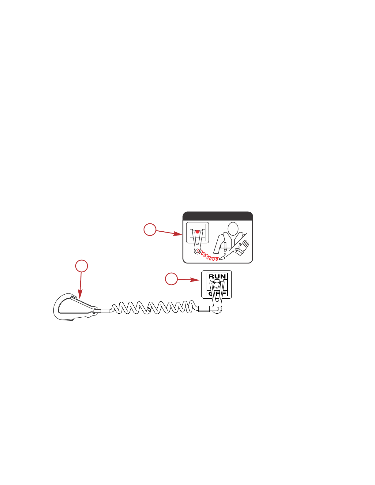
Lanyard Stop Switch
The purpose of a lanyard stop switch is to turn off the engine when the operator
moves far enough away from the operator's position (as in accidental ejection
from the operator's position) to activate the switch. Tiller handle outboards and
some remote control units are equipped with a lanyard stop switch. A lanyard
stop switch can be installed as an accessory ‑ generally on the dashboard or
side adjacent to the operator's position.
A decal near the lanyard stop switch is a visual reminder for the operator to
attach the lanyard to their personal flotation device (PFD) or wrist.
The lanyard cord is usually 122–152 cm (4–5 feet) in length when stretched out,
with an element on one end made to be inserted into the switch and a clip on
the other end for attaching to the operator's PFD or wrist. The lanyard is coiled
to make its at‑rest condition as short as possible to minimize the likelihood of
lanyard entanglement with nearby objects. Its stretched‑out length is made to
minimize the likelihood of accidental activation should the operator choose to
move around in an area close to the normal operator's position. If it is desired
to have a shorter lanyard, wrap the lanyard around the operator's wrist or leg,
or tie a knot in the lanyard.
a - Lanyard cord clip
b - Lanyard decal
c - Lanyard stop switch
Read the following Safety Information before proceeding.
c
a
b
53910
OFF
RUN
ATTACH LANYARD
GENERAL INFORMATION
4 eng
Page 15
Important Safety Information: The purpose of a lanyard stop switch is to stop
the engine when the operator moves far enough away from the operator's
position to activate the switch. This would occur if the operator accidentally falls
overboard or moves within the boat a sufficient distance from the operator's
position. Falling overboard and accidental ejections are more likely to occur in
certain types of boats such as low sided inflatables, bass boats, high
performance boats, and light, sensitive handling fishing boats operated by a
hand tiller. Falling overboard and accidental ejections are also likely to occur as
a result of poor operating practices such as sitting on the back of the seat or
gunwale at planing speeds, standing at planing speeds, sitting on elevated
fishing boat decks, operating at planing speeds in shallow or obstacle infested
waters, releasing your grip on a steering wheel or tiller handle that is pulling in
one direction, drinking alcohol or consuming drugs, or daring high speed boat
maneuvers.
While activation of the lanyard stop switch will stop the engine immediately, a
boat will continue to coast for some distance depending upon the velocity and
degree of any turn at shut down. However, the boat will not complete a full
circle. While the boat is coasting, it can cause injury to anyone in the boat's
path as seriously as the boat would when under power.
We strongly recommend that other occupants be instructed on proper starting
and operating procedures should they be required to operate the engine in an
emergency (if the operator is accidentally ejected).
!
WARNING
If the operator falls out of the boat, stop the engine immediately to reduce the
possibility of serious injury or death from being struck by the boat. Always
properly connect the operator to the stop switch using a lanyard.
!
WARNING
Avoid serious injury or death from deceleration forces resulting from
accidental or unintended stop switch activation. The boat operator should
never leave the operator's station without first disconnecting the stop switch
lanyard from the operator.
Accidental or unintended activation of the switch during normal operation is
also a possibility. This could cause any, or all, of the following potentially
hazardous situations:
• Occupants could be thrown forward due to unexpected loss of forward
motion ‑ a particular concern for passengers in the front of the boat who
could be ejected over the bow and possibly struck by the gearcase or
propeller.
• Loss of power and directional control in heavy seas, strong current, or
high winds.
• Loss of control when docking.
GENERAL INFORMATION
eng 5
Page 16

KEEP THE LANYARD STOP SWITCH AND LANYARD CORD IN GOOD
OPERATING CONDITION
Before each use, check to ensure the lanyard stop switch works properly. Start
the engine and stop it by pulling the lanyard cord. If the engine does not stop,
have the switch repaired before operating the boat.
Before each use, visually inspect the lanyard cord to ensure it is in good
working condition and that there are no breaks, cuts, or wear to the cord.
Check that the clips on the ends of the cord are in good condition. Replace any
damaged or worn lanyard cords.
Stopping the Boat in an Emergency
A jet powered boat has emergency stopping capability unique to this form of
propulsion.
!
WARNING
Using the emergency stopping capability of a jet drive unit will slow down the
boat in an emergency. However, sudden stopping may cause the occupants
of the boat to be thrown forward or out of the boat resulting in serious injury
or death. Use caution when performing the emergency stopping procedure,
and be sure to practice in a safe area.
In an emergency, putting the jet outboard into reverse and applying reverse
throttle can rapidly slow down the boat and reduce stopping distance. However,
such a maneuver may cause occupants in the boat to be thrown forward or
possibly out of the boat.
Protecting People In The Water
WHILE YOU ARE CRUISING
It is very difficult for a person standing or floating in the water to take quick
action to avoid a boat heading in his/her direction, even at slow speed.
21604
Always slow down and exercise extreme caution when boating in an area
where there might be people in the water.
Avoid shallow water or where any loose material such as sand, shells,
seaweed, grass, tree branches, etc., can be pulled in and expelled from the
pump as a high speed projectile.
GENERAL INFORMATION
6 eng
Page 17
WHILE BOAT IS STATIONARY
!
WARNING
Avoid injury resulting from contacting the rotating impeller or having hair,
clothing, or loose objects drawn into the water intake and wrapping around
the impeller shaft. Stay away from the water intake and never insert an object
into the water intake or water outlet nozzle when the engine is running.
Stop the engine immediately whenever a person is in the water near the boat.
The jet drive is always drawing water through the water intake when the engine
is running. Stay away from the water intake located under the jet drive and
never insert an object into the water intake or outlet nozzle when the engine is
running.
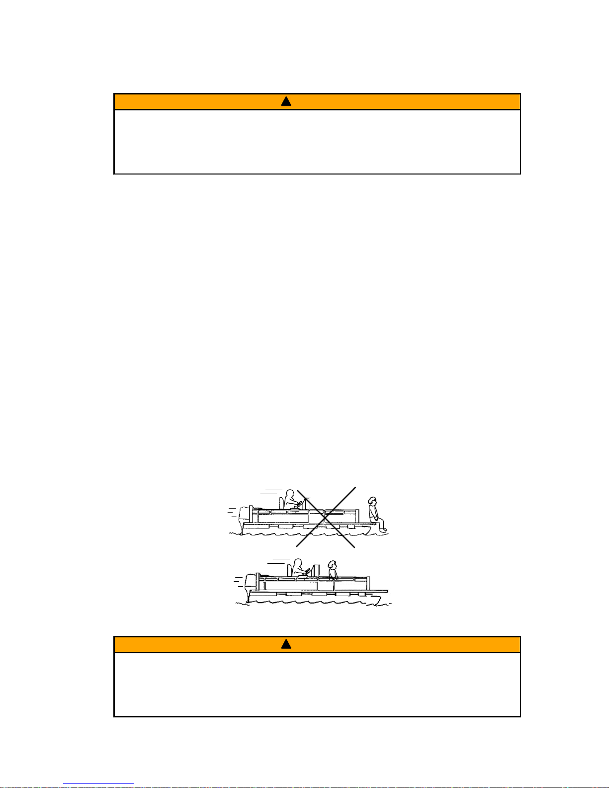
Passenger Safety Message ‑ Pontoon Boats and Deck Boats
Whenever the boat is in motion, observe the location of all passengers. Do not
allow any passengers to stand or use seats other than those designated for
traveling faster than idle speed. A sudden reduction in boat speed, such as
plunging into a large wave or wake, a sudden throttle reduction, or a sharp
change of boat direction, could throw them over the front of the boat. Falling
over the front of the boat between the two pontoons will position them to be run
over by the outboard.
BOATS HAVING AN OPEN FRONT DECK
No one should ever be on the deck in front of the fence while the boat is in
motion. Keep all passengers behind the front fence or enclosure.
Persons on the front deck could easily be thrown overboard or persons
dangling their feet over the front edge could get their legs caught by a wave
and pulled into the water.
26782
!
WARNING
Sitting or standing in an area of the boat not designed for passengers at
speeds above idle can cause serious injury or death. Stay back from the front
end of deck boats or raised platforms and remain seated while the boat is in
motion.
GENERAL INFORMATION
eng 7
Page 18
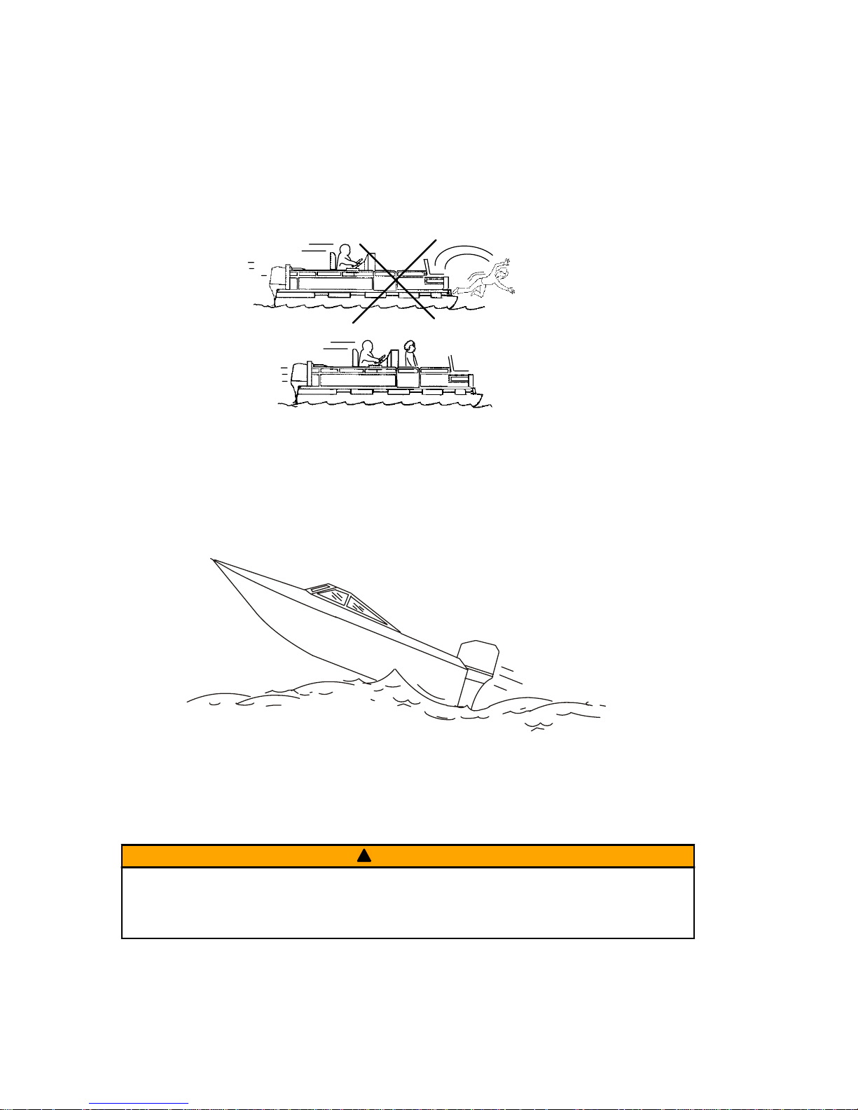
BOATS WITH FRONT MOUNTED, RAISED PEDESTAL FISHING SEATS
Elevated fishing seats are not intended for use when the boat is traveling faster
than idle or trolling speed. Sit only in seats designated for traveling at faster
speeds.
Any unexpected, sudden reduction in boat speed could result in the elevated
passenger falling over the front of the boat.
26783
Wave and Wake Jumping
Operating recreational boats over waves and wake is a natural part of boating.
However, when this activity is done with sufficient speed to force the boat hull
partially or completely out of the water, certain hazards arise, particularly when
the boat enters the water.
26784
The primary concern is the boat changing direction while in the midst of the
jump. In such case, the landing may cause the boat to veer violently in a new
direction. Such a sharp change in direction can cause occupants to be thrown
out of their seats, or out of the boat.
!
WARNING
Wave or wake jumping can cause serious injury or death from occupants
being thrown within or out of the boat. Avoid wave or wake jumping whenever
possible.
GENERAL INFORMATION
8 eng
Page 19
There is another less common hazardous result from allowing your boat to
launch off a wave or wake. If the bow of your boat pitches down far enough
while airborne, upon water contact it may penetrate under the water surface
and submarine for an instant. This will bring the boat to a nearly instantaneous
stop and can send the occupants flying forward. The boat may also steer
sharply to one side.
Safety Instructions for Hand‑Tilled Outboards
No person or cargo should occupy the area directly in front of the outboard
while the boat is in motion. If an underwater obstacle is struck, the outboard will
tilt up and could seriously injure anyone occupying this area.
MODELS WITH CLAMP SCREWS:
Some outboards come with transom bracket clamp screws. The use of clamp
bracket screws alone, is insufficient to properly and safely secure the outboard
to the transom. Proper installation of the outboard includes bolting the engine to
the boat through the transom. Refer to Installation ‑ Installing Outboard for
more complete installation information.
!
WARNING
Failure to correctly fasten the outboard could result in the outboard propelling
off the boat transom resulting in property damage, serious injury, or death.
Before operation, the outboard must be correctly installed with the required
mounting hardware.
If an obstacle is struck at planing speed and the outboard is not securely
fastened to the transom, it is possible the outboard could lift off the transom
and land in the boat.
Exhaust Emissions
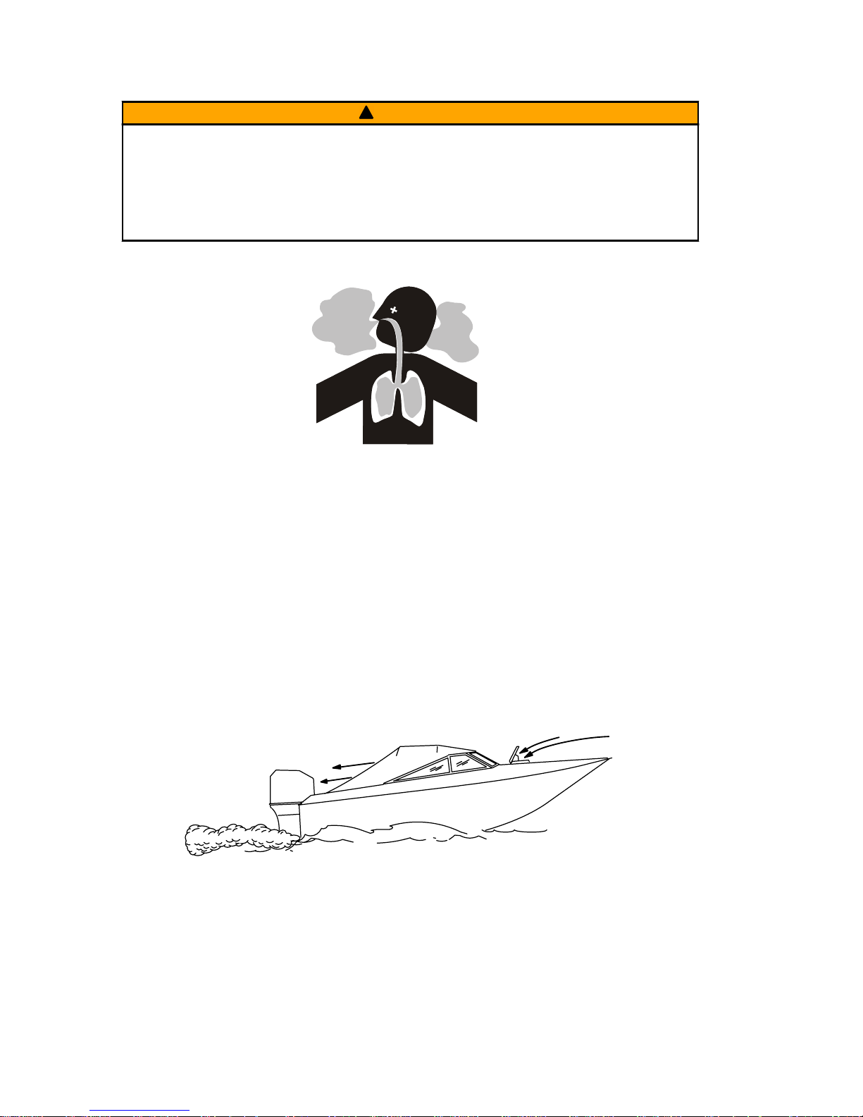
BE ALERT TO CARBON MONOXIDE POISONING
Carbon monoxide (CO) is a deadly gas that is present in the exhaust fumes of
all internal combustion engines, including the engines that propel boats, and
the generators that power boat accessories. By itself, CO is odorless, colorless,
and tasteless, but if you can smell or taste engine exhaust, you are inhaling
CO.
Early symptoms of carbon monoxide poisoning, which are similar to the
symptoms of seasickness and intoxication, include headache, dizziness,
drowsiness, and nausea.
GENERAL INFORMATION
eng 9
Page 20
!
WARNING
Inhaling engine exhaust gases can result in carbon monoxide poisoning,
which can lead to unconsciousness, brain damage, or death. Avoid exposure
to carbon monoxide.
Stay clear from exhaust areas when engine is running. Keep the boat
well‑ventilated while at rest or underway.
STAY CLEAR OF EXHAUST AREAS
Engine exhaust gases contain harmful carbon monoxide. Avoid areas of
concentrated engine exhaust gases. When engines are running, keep
swimmers away from the boat, and do not sit, lie, or stand on swim platforms or
boarding ladders. While underway, do not allow passengers to be positioned
immediately behind the boat (platform dragging, teak/body surfing). This
dangerous practice not only places a person in an area of high engine exhaust
concentration, but also subjects them to the possibility of injury from the boat
propeller.
GOOD VENTILATION
Ventilate the passenger area, open side curtains or forward hatches to remove
fumes.
Example of desired air flow through the boat:
21622
POOR VENTILATION
Under certain running and/or wind conditions, permanently enclosed or canvas
enclosed cabins or cockpits with insufficient ventilation may draw in carbon
monoxide. Install one or more carbon monoxide detectors in your boat.
Although the occurrence is rare, on a very calm day, swimmers and
passengers in an open area of a stationary boat that contains, or is near, a
running engine may be exposed to a hazardous level of carbon monoxide.
GENERAL INFORMATION
10 eng
Page 21
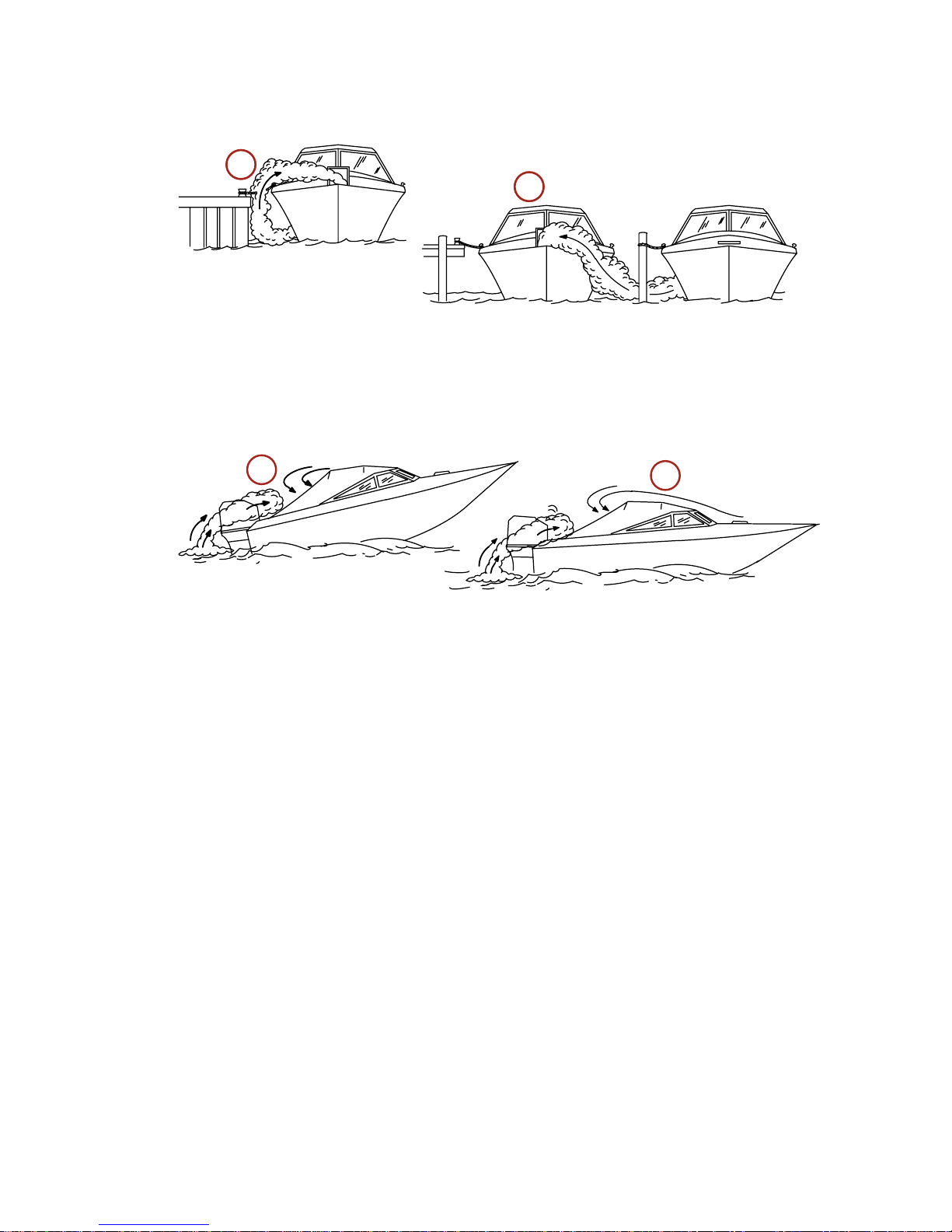
1. Examples of poor ventilation while the boat is stationary:
a - Operating the engine when the boat is moored in a confined space
b - Mooring close to another boat that has its engine operating
2. Examples of poor ventilation while the boat is moving:
a - Operating the boat with the trim angle of the bow too high
b - Operating the boat with no forward hatches open (station wagon effect)
Selecting Accessories for Your Outboard
Genuine Mercury Precision or Quicksilver Accessories have been specifically
designed and tested for your outboard. These accessories are available from
Mercury Marine dealers.
IMPORTANT: Check with your dealer before installing accessories. The misuse
of approved accessories or the use of nonapproved accessories can damage
the product.
Some accessories not manufactured or sold by Mercury Marine are not
designed to be safely used with your outboard or outboard operating system.
Read the installation, operation and maintenance manuals for all your selected
accessories.
Refer to Outboard Installation ‑ Accessories Mounted to the Transom
Clamp Bracket for important information on mounting accessories to the
transom clamp bracket.
Safe Boating Recommendations
To safely enjoy the waterways, familiarize yourself with local and all other
governmental boating regulations and restrictions and consider the following
suggestions.
21626
a
b
a
b
21628
GENERAL INFORMATION
eng 11
Page 22

Know and obey all nautical rules and laws of the waterways.
• We recommend that all powerboat operators complete a boating safety
course. In the U.S., the U.S. Coast Guard Auxiliary, the Power Squadron,
the Red Cross, and your state or provincial boating law enforcement
agency provide courses. For more information in the U.S., call the Boat
U.S. Foundation at 1‑800‑336‑BOAT (2628).
Perform safety checks and required maintenance.
• Follow a regular schedule and ensure that all repairs are properly made.
Check safety equipment onboard.
• Here are some suggestions of the types of safety equipment to carry
when boating:
Approved fire extinguishers
Signal devices: flashlight, rockets or flares, flag, and whistle or horn
Tools necessary for minor repairs
Anchor and extra anchor line
Manual bilge pump and extra drain plugs
Drinking water
Radio
Paddle or oar
Spare propeller, thrust hubs, and an appropriate wrench
First aid kit and instructions
Waterproof storage containers
Spare operating equipment, batteries, bulbs, and fuses
Compass and map or chart of the area
Personal flotation device (one per person onboard)
Watch for signs of weather change and avoid foul weather and rough‑sea
boating.
Tell someone where you are going and when you expect to return.
Passenger boarding.
• Stop the engine whenever passengers are boarding, unloading, or are
near the back (stern) of the boat. Shifting the drive unit into neutral is not
sufficient.
Use personal flotation devices.
• Federal law requires that there be a U.S. Coast Guard‑approved life
jacket (personal flotation device), correctly sized and readily accessible
for every person onboard, plus a throwable cushion or ring. We strongly
advise that everyone wear a life jacket at all times while in the boat.
GENERAL INFORMATION
12 eng
Page 23

Prepare other boat operators.
• Instruct at least one person onboard in the basics of starting and
operating the engine and boat handling in case the driver becomes
disabled or falls overboard.
Do not overload your boat.
• Most boats are rated and certified for maximum load (weight) capacities
(refer to your boat's capacity plate). Know your boat's operating and
loading limitations. Know if your boat will float if it is full of water. When in
doubt, contact your authorized Mercury Marine dealer or the boat
manufacturer.
Ensure that everyone in the boat is properly seated.
• Do not allow anyone to sit or ride on any part of the boat that was not
intended for such use. This includes the backs of seats, gunwales,
transom, bow, decks, raised fishing seats, and any rotating fishing seat.
Passengers should not sit or ride anywhere that sudden unexpected
acceleration, sudden stopping, unexpected loss of boat control, or sudden
boat movement could cause a person to be thrown overboard or into the
boat. Ensure that all passengers have a proper seat and are in it before
any boat movement.
Never operate a boat while under the influence of alcohol or drugs. It is
the law.
• Alcohol or drugs can impair your judgment and greatly reduce your ability
to react quickly.
Know your boating area and avoid hazardous locations.
Be alert.
• The operator of the boat is responsible by law to maintain a proper
lookout by sight and hearing. The operator must have an unobstructed
view particularly to the front. No passengers, load, or fishing seats should
block the operator's view when the boat is above idle or planing transition
speed. Watch out for others, the water, and your wake.
Never drive your boat directly behind a water skier.
• Your boat traveling at 40 km/h (25 mph) will overtake a fallen skier who is
61 m (200 ft) in front of you in five seconds.
Watch fallen skiers.
• When using your boat for waterskiing or similar activities, always keep a
fallen or down skier on the operator's side of the boat while returning to
attend to the skier. The operator should always have the down skier in
sight and never back up to the skier or anyone in the water.
Report accidents.
GENERAL INFORMATION
eng 13
Page 24
• Boat operators are required by law to file a boating accident report with
their state boating law enforcement agency when their boat is involved in
certain boating accidents. A boating accident must be reported if 1) there
is loss of life or probable loss of life, 2) there is personal injury requiring
medical treatment beyond first aid, 3) there is damage to boats or other
property where the damage value exceeds $500.00, or 4) there is
complete loss of the boat. Seek further assistance from local law
enforcement.
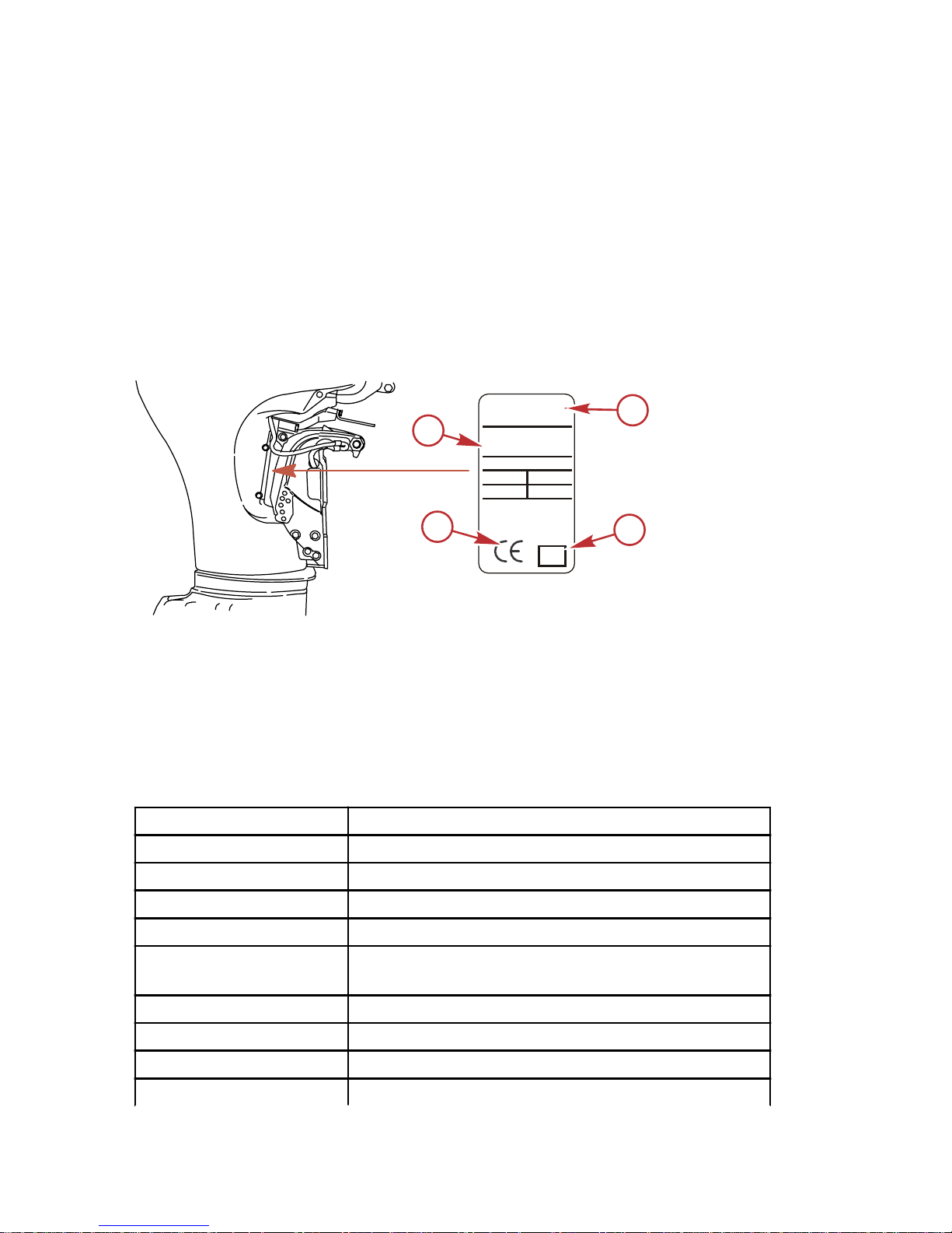
Recording Serial Number
It is important to record this number for future reference. The serial number is
located on the outboard as shown.
a - Serial number
b - Model designation
c - Year manufactured
d - Certified Europe Insignia (as applicable)
40 Jet FourStroke Specifications
Models
40 Jet
Horsepower 40
Kilowatts 29.4
Full throttle RPM range 5000–5500 RPM
Number of cylinders 4
Idle speed in forward
gear
Controlled by ECM
Piston displacement 995 cc (60.8 in³)
Cylinder bore 65 mm (2.559 in.)
Stroke 75 mm (2.953 in.)
Valve clearance (cold)
24125
H
P
L
B
- - - . -
- -
XXXXXXX
-
XXXXX XX
XL
Mercury
Marine
Serial Number
Brunswick Corp.
Made in Japan
XX
XXXX XXX
HP XXX
LB XXX
KG XXX
KW XXX
Model Number
b
c
a
d
GENERAL INFORMATION
14 eng
Page 25

Models 40 Jet
Intake valve 0.15–0.25 mm (0.006–0.010 in.)
Exhaust valve 0.25–0.35 mm (0.010–0.014 in.)
Recommended spark
plug
Champion RA8HC
Spark plug gap 1.0 mm (0.040 in.)
Recommended gasoline
Refer to Fuel and Oil
Recommended oil
Refer to Fuel and Oil
Engine oil capacity 3.0 L (3 US qt)
Emission control system Electronic engine control (EC)
Battery rating*
Operation above 0 °C
(32 °F)
465 marine cranking amps (MCA) or 350 cold
cranking amps (CCA)
Operation below 0 °C
(32 °F)
1000 marine cranking amps (MCA) or 750 cold
cranking amps (CCA)
Ampere hours (Ah) 70–100
*Battery manufacturers may rate and test their batteries to different standards.
MCA, CCA, Ah, and reserve capacity (RC) are the ratings recognized by
Mercury Marine. Manufacturers that use standards different than these, such
as equivalent MCA, do not meet Mercury Marine battery requirements.
Component Identification
a - Auxiliary tilt switch
b - Tilt support knob
c - Transom brackets
d - Jet drive housing
e - Water intake housing
f - Reverse gate
g - Water outlet nozzle
h - Driveshaft housing
i - Water pump indicator hole
j - Bottom cowl
k - Top cowl
a
b
c
d
e
f
g
h
i
j
k
28684
GENERAL INFORMATION
eng 15
Page 26

Trailering Boat/Outboard
The boat should be trailered with the outboard tilted down in a vertical
operating position.
IMPORTANT: Do not rely on the power trim/tilt system or tilt support lever to
maintain proper ground clearance for trailering. The outboard tilt support lever
is not intended to support the outboard for trailering.
If additional ground clearance is required, the outboard should be tilted up
using an accessory outboard support device. Refer to your local dealer for
recommendations. Additional clearance may be required for railroad crossings,
driveways and trailer bouncing.
TRANSPORTING
16 eng
Page 27

Fuel Requirements
IMPORTANT: Use of improper gasoline can damage your engine. Engine
damage resulting from the use of improper gasoline is considered misuse
of the engine and will not be covered under the limited warranty.
FUEL RATINGS
Mercury outboard engines will operate satisfactorily with any major brand of
unleaded gasoline that meets the following specifications:
USA and Canada ‑ A posted pump octane rating of 87 (R+M)/2, minimum, for
most models. Premium gasoline 91 (R+M)/2 octane is also acceptable for most
models. Do not use leaded gasoline.
Outside USA and Canada ‑ A posted pump octane rating of 91 RON,
minimum, for most models. Premium gasoline (95 RON) is also acceptable for
all models. Do not use leaded gasoline.
USING REFORMULATED (OXYGENATED) GASOLINE (USA ONLY)
Reformulated gasoline is required in certain areas of the USA and is
acceptable for use in your Mercury Marine engine. The only oxygenate
currently in use in the USA is alcohol (ethanol, methanol, or butanol).
GASOLINE CONTAINING ALCOHOL
Bu16 Butanol Fuel Blends
Fuel blends of up to 16.1% butanol (Bu16) that meet the published Mercury
Marine fuel rating requirements are an acceptable substitute for unleaded
gasoline. Contact your boat manufacturer for specific recommendations on
your boat's fuel system components (fuel tanks, fuel lines, and fittings).
Methanol and Ethanol Fuel Blends
IMPORTANT: The fuel system components on your Mercury Marine engine will
withstand up to 10% alcohol (methanol or ethanol) content in the gasoline. Your
boat's fuel system may not be capable of withstanding the same percentage of
alcohol. Contact your boat manufacturer for specific recommendations on your
boat's fuel system components (fuel tanks, fuel lines, and fittings).
Be aware that gasoline containing methanol or ethanol may cause increased:
• Corrosion of metal parts
• Deterioration of rubber or plastic parts
• Fuel permeation through the rubber fuel lines
• Likelihood of phase separation (water and alcohol separating from the
gasoline in the fuel tank)
FUEL AND OIL
eng 17
Page 28

!
WARNING
Fuel leakage is a fire or explosion hazard, which can cause serious injury or
death. Periodically inspect all fuel system components for leaks, softening,
hardening, swelling, or corrosion, particularly after storage. Any sign of
leakage or deterioration requires replacement before further engine
operation.
IMPORTANT: If you use gasoline that contains or might contain methanol or
ethanol, you must increase the frequency of inspection for leaks and
abnormalities.
IMPORTANT: When operating a Mercury Marine engine on gasoline containing
methanol or ethanol, do not store the gasoline in the fuel tank for long periods.
Cars normally consume these blended fuels before they can absorb enough
moisture to cause trouble; boats often sit idle long enough for phase separation
to take place. Internal corrosion may occur during storage if alcohol has
washed protective oil films from internal components.
Low Permeation Fuel Hose Requirement
Required for outboards manufactured for sale, sold, or offered for sale in the
United States.
• The Environmental Protection Agency (EPA) requires that any outboard
manufactured after January 1, 2009, must use low permeation fuel hose
for the primary fuel hose connecting the fuel tank to the outboard.
• Low permeation hose is USCG Type B1‑15 or Type A1‑15, defined as not
exceeding 15 g/m²/24 h with CE 10 fuel at 23 °C as specified in SAE J
1527 ‑ marine fuel hose.
EPA Pressurized Portable Fuel Tank Requirements
The Environmental Protection Agency (EPA) requires portable fuel systems
that are produced after January 1, 2011, for use with outboard engines to
remain fully sealed (pressurized) up to 34.4 kPa (5.0 psi). These tanks may
contain the following:
• An air inlet that opens to allow air to enter as the fuel is drawn out of the
tank.
• An air outlet that opens (vents) to the atmosphere if pressure exceeds
34.4 kPa (5.0 psi).
Fuel Demand Valve (FDV) Requirement
Whenever a pressurized fuel tank is used, a fuel demand valve is required to
be installed in the fuel hose between the fuel tank and primer bulb. The fuel
demand valve prevents pressurized fuel from entering the engine and causing
a fuel system overflow or possible fuel spillage.
FUEL AND OIL
18 eng
Page 29
The fuel demand valve has a manual release. The manual release can be used
(pushed in) to open (bypass) the valve in case of a fuel blockage in the valve.
a - Fuel demand valve ‑ installed in the
fuel hose between the fuel tank and
primer bulb
b - Manual release
c - Vent/water drain holes
Mercury Marine's Pressurized Portable Fuel Tank
Mercury Marine has created a new portable pressurized fuel tank that meets
the preceding EPA requirements. These fuel tanks are available as an
accessory or are provided with certain portable outboard models.
SPECIAL FEATURES OF THE PORTABLE FUEL TANK
• The fuel tank has a two‑way valve which allows air to enter the tank as
the fuel is drawn to the engine, and also opens to vent to the atmosphere
if internal pressure in the tank exceeds 34.4 kPa (5.0 psi). A hissing noise
may be heard as the tank vents to the atmosphere. This is normal.
• The fuel tank includes a fuel demand valve that prevents pressurized fuel
from entering the engine and causing a fuel system overflow or possible
fuel spillage.
• When installing the fuel tank cap, turn the cap to the right until you hear a
click. This signals that the fuel cap is fully seated. A built‑in device
prevents overtightening.
• The fuel tank has a manual vent screw which should be closed for
transportation and open for operation and cap removal.
Since sealed fuel tanks are not vented, they will expand and contract as the
fuel expands and contracts during heating and cooling cycles of the outside air.
This is normal.
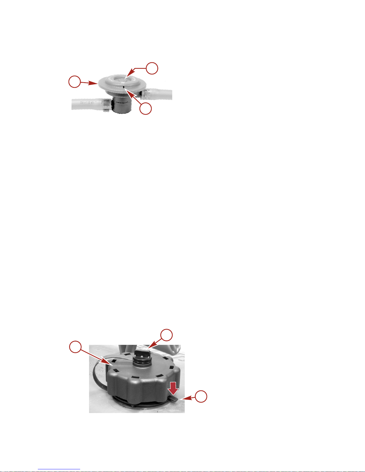
REMOVING THE FUEL CAP
a - Fuel cap
b - Manual vent screw
c - Tab lock
IMPORTANT: Contents may be under pressure. Rotate the fuel cap 1/4 turn to
relieve pressure before opening.
a
c
b
46273
a
b
c
46290
FUEL AND OIL
eng 19
Page 30

1. Open the manual vent screw on top of the fuel cap.
2. Turn the fuel cap until it contacts the tab lock.
3. Press down on the tab lock. Rotate the fuel cap 1/4 turn to relieve the
pressure.
4. Press down on the tab lock again and remove the cap.
DIRECTIONS FOR USING THE PRESSURIZED PORTABLE FUEL TANK
1. When installing the fuel tank cap, turn the cap to the right until you hear a
click. This signals that the fuel cap is fully seated. A built‑in device
prevents overtightening.
2. Open the manual vent screw on top of the cap for operation and cap
removal. Close the manual vent screw for transportation.
3. For fuel hoses that have quick disconnects, disconnect the fuel line from
the engine or fuel tank when not in use.
4.
Follow Filling Fuel Tank instructions for fueling.
Filling Fuel Tank
!
WARNING
Avoid serious injury or death from a gasoline fire or explosion. Use caution
when filling fuel tanks. Always stop the engine and do not smoke or allow
open flames or sparks in the area while filling fuel tanks.
Fill the fuel tanks outdoors away from heat, sparks, and open flames.
Remove the portable fuel tanks from the boat to fill them.
Always stop the engine before filling the tanks.
Do not completely fill the fuel tanks. Leave approximately 10% of the tank
volume unfilled. Fuel will expand in volume as its temperature rises and can
leak under pressure if the tank is completely filled.
PORTABLE FUEL TANK PLACEMENT IN THE BOAT
Place the fuel tank in the boat so the vent is higher than the fuel level under
normal boat operating conditions.
Engine Oil Recommendations
Mercury or Quicksilver NMMA FC‑W certified SAE 10W‑30 4‑Stroke Marine
Engine Oil is recommended for general, all‑temperature use. If NMMA certified
synthetic blend oil is preferred, use Mercury or Quicksilver SAE 25W‑40
Synthetic Blend Marine 4‑Stroke Engine Oil. If the recommended Mercury or
Quicksilver NMMA FC‑W certified outboard oils are not available, a major
FC‑W certified 4‑stroke outboard oil may be used.
FUEL AND OIL
20 eng
Page 31

IMPORTANT: The use of nondetergent oils, multi‑viscosity oils (other than
Mercury or Quicksilver NMMA FC‑W certified oil or a major brand NMMA FC‑W
certified oil), synthetic oils, low quality or oils that contain solid additives are not
recommended.
Recommended SAE viscosity for
engine oil
a - Mercury or Quicksilver SAE
25W‑40 Synthetic Blend Marine
4‑Stroke Engine Oil may be used
at temperatures above 4 °C
(40 °F)
b - Mercury or Quicksilver SAE
10W‑30 4‑Stroke Marine Engine
Oil is recommended for use in all
temperatures
Checking and Adding Engine Oil
IMPORTANT: Do not overfill. Be sure that the outboard is upright (not tilted)
when checking oil.
1. Turn the engine off. Have the outboard in a level operating position.
Remove the top cowl.
2. Flip the handle up and pull out the dipstick. Wipe it with a clean rag or
towel and push it back in all the way.
3. Pull the dipstick back out again and observe the oil level. If the oil level is
low, remove the oil filler cap and fill to (but not over) the upper oil level
with the recommended oil.
IMPORTANT: Inspect oil for signs of contamination. Oil contaminated with
water will have a milky color to it; oil contaminated with fuel will have a strong
fuel smell. If contaminated oil is noticed, have the engine checked by your
dealer.
+20
+40
+60
+80
F° C°
0
+100
–7
+4
+16
+27
–18
+38
a
b
26795
FUEL AND OIL
eng 21
Page 32

4. Push the dipstick back in all the way, then flip the handle down to lock the
dipstick in place. Reinstall the oil filler cap and hand tighten securely.
a - Full mark
b - Add mark
c - Dipstick
d - Oil filler cap
a
b
c
d
28412
FUEL AND OIL
22 eng
Page 33

Remote Control Features
Your boat may be equipped with one of the Mercury Precision or Quicksilver
remote controls shown. If not, consult your dealer for a description of the
functions and operations of the remote control.
a - Control handle – forward, neutral, reverse
b - Neutral release lever
c -
Trim/tilt switch (if equipped) – Refer to Features and Controls –
Power Trim and Tilt
d -
Lanyard stop switch – Refer to General Information – Lanyard Stop
Switch
e -
Lanyard – Refer to General Information – Lanyard Stop Switch
f - Throttle friction adjustment – Console controls require cover removal for
adjustment
g - Ignition key switch – "OFF," "ON," START"
h -
Fast idle lever – Refer to Operation – Starting the Engine
i -
Throttle only button – Refer to Operation – Starting the Engine
f
a
c
d
e
b
h
c
a
g
d
e
b
i
f
g
i
c
a
f
26800
FEATURES AND CONTROLS
eng 23
Page 34

Warning System
WARNING HORN SIGNALS
The outboard warning system incorporates a warning horn inside the boat.
Remote control models will have the warning horn located inside the remote
control or connected to the ignition key switch. Tiller handle models will have
the warning horn located in the ignition key panel.
a - Horn inside remote control
b - Horn connected to ignition key switch
c - Horn in ignition key panel
There are two types of warning horns to alert the operator of an active problem
within the engine's operating system.
1.
Continuous six second beep: Indicates a critical engine condition.
Depending on the condition, the Engine Guardian System may engage
and protect the engine by limiting its power. You should return to port
immediately and contact your servicing dealer.
2.
Intermittent short beeps for six seconds: Indicates a noncritical engine
condition. This condition does not require immediate attention. You may
continue using your boat, however, depending on the nature of the
problem, the engine’s power may be limited by the Engine Guardian
System (see Engine Guardian System following) to protect the engine.
You should contact your servicing dealer at your earliest convenience.
It is important to note that in either of the above scenarios, the horn will only
sound one time. If you key the engine off and restart it, the horn will sound
again, one time, if the fault is still present. For visual display of the specific
engine functions and additional engine data, refer to SmartCraft Product
information, following.
The operator is able to correct a couple engine problems indicated by the
warning horn. These conditions are as follows:
• Cooling system (water pressure or engine temperature) problem. The
warning horn will sound Intermittent short beeps for six seconds. Stop the
engine and check the water intake holes in the gearcase for obstruction.
• Low oil pressure problem. The warning horn will sound a continuous six
second beep. Stop the engine and check for low engine oil level. Refer to
Fuel and Oil – Checking and Adding Engine Oil.
a
b
c
26801
FEATURES AND CONTROLS
24 eng
Page 35

ENGINE GUARDIAN SYSTEM
The Engine Guardian System monitors the critical sensors on the engine for
any early indications of problems. Engine Guardian is functional whenever your
engine is operating, so you never have to be concerned about whether or not
you are protected. The system will respond to a problem by sounding the
warning horn for six seconds and/or reducing engine power in order to provide
engine protection.
If the Guardian System has been activated, reduce throttle speed. The problem
will need to be identified and corrected, if possible. The system must be reset
before the engine will operate at higher speeds. Moving the throttle lever back
to the idle position will reset the system.
SMARTCRAFT PRODUCT
A Mercury SmartCraft System instrument package can be purchased for this
outboard. A few of the functions the instrument package will display are engine
RPM, coolant temperature, oil pressure, water pressure, battery voltage, fuel
consumption, and engine operating hours.
The SmartCraft instrument package will also aid in Engine Guardian
diagnostics. The SmartCraft Instrument package will display critical engine
alarm data and potential problems.
FEATURES AND CONTROLS
eng 25
Page 36

Power Trim and Tilt
Your outboard has a trim/tilt control called power trim. This enables the
operator to easily adjust the position of the outboard by pressing the trim
switch. Moving the outboard in closer to the boat transom is called trimming in
or down. Moving the outboard further away from the boat transom is called
trimming out or up. The term trim generally refers to the adjustment of the
outboard within the first 20° range of travel. This is the range used while
operating your boat on plane. The term tilt is generally used when referring to
adjusting the outboard further up out of the water. With the engine turned off,
the outboard can be tilted out of the water. At low idle speed, the outboard can
also be tilted up past the trim range to permit, for example, shallow water
operation.
a - Remote control trim switch
b - Panel mount trim switch
c - Tilt range of travel
d - Trim range of travel
POWER TRIM OPERATION
With most boats, operating around the middle of the trim range will give
satisfactory results. However, to take full advantage of the trimming capability
there may be times when you choose to trim your outboard all the way in or
out. Along with an improvement in some performance aspects comes a greater
responsibility for the operator, and this is being aware of some potential control
hazards.
The most significant control hazard is a pull or torque that can be felt on the
steering wheel or tiller handle. This steering torque results from the outboard
being trimmed so that the propeller shaft is not parallel to the water surface.
d
a
b
c
28710
FEATURES AND CONTROLS
26 eng
Page 37

!
WARNING
Trimming the outboard beyond a neutral steering condition may result in a
pull on the steering wheel or tiller handle and loss of boat control. Maintain
control of the boat if trimming beyond a neutral steering condition.
Consider the following lists carefully.
Trimming in or down can:
• Lower the bow
• Result in quicker planing off, especially with a heavy load or a stern heavy
boat
• Generally improve the ride in choppy water
• Increase steering torque or pull to the right (with the normal right hand
rotation propeller)
• In excess, can lower the bow of some boats to a point where they begin to
plow with their bow in the water while on plane. This can result in an
unexpected turn in either direction (called bow steering or oversteering) if
any turn is attempted, or if a significant wave is encountered.
!
WARNING
Operating the boat at high speeds with the outboard trimmed too far under
can create excessive bow steer, resulting in the operator losing control of
the boat. Install the trim limit pin in a position that prevents excessive trim
under and operate the boat in a safe manner.
• In rare circumstances, the owner may decide to limit the trim in. This can
be accomplished by repositioning the tilt stop pins into the desired
transom bracket adjustment holes.
Trimming out or up can:
• Lift the bow higher out of the water
• Generally increase top speed
• Increase clearance over submerged objects or a shallow bottom
• Increase steering torque or pull to the left at a normal installation height
(with the normal right hand rotation propeller)
• In excess, can cause boat porpoising (bouncing) or propeller ventilation
• Cause engine overheating if any cooling water intake holes are above the
waterline
TILTING OPERATION
To tilt outboard, shut off the engine and press the trim/tilt switch or auxiliary tilt
switch to the up position. The outboard will tilt up until the switch is released or
it reaches its maximum tilt position.
1. Engage the tilt support lever, by rotating knob to bring the support lever
upward.
FEATURES AND CONTROLS
eng 27
Page 38

2. Lower outboard to rest on the tilt support lever.
3. Disengage the tilt support lever, by raising the outboard off the support
lever and rotating the lever down. Lower the outboard.
a - Tilt support lever
b - Knob
MANUAL TILTING
If the outboard cannot be tilted using the power trim/tilt switch, the outboard can
be manually tilted.
1. Turn out the manual tilt release valve three turns counterclockwise. This
allows manual tilting of the outboard. Tilt the outboard to the desired
position and tighten the manual tilt release valve.
26809
NOTE: The manual tilt release valve must be tightened before operating the
outboard to prevent the outboard from tilting up during reverse operation.
AUXILIARY TILT SWITCH
The auxiliary tilt switch can be used to tilt the outboard up or down using the
power trim system.
a - Auxiliary tilt switch
a
b
28931
a
28534
FEATURES AND CONTROLS
28 eng
Page 39

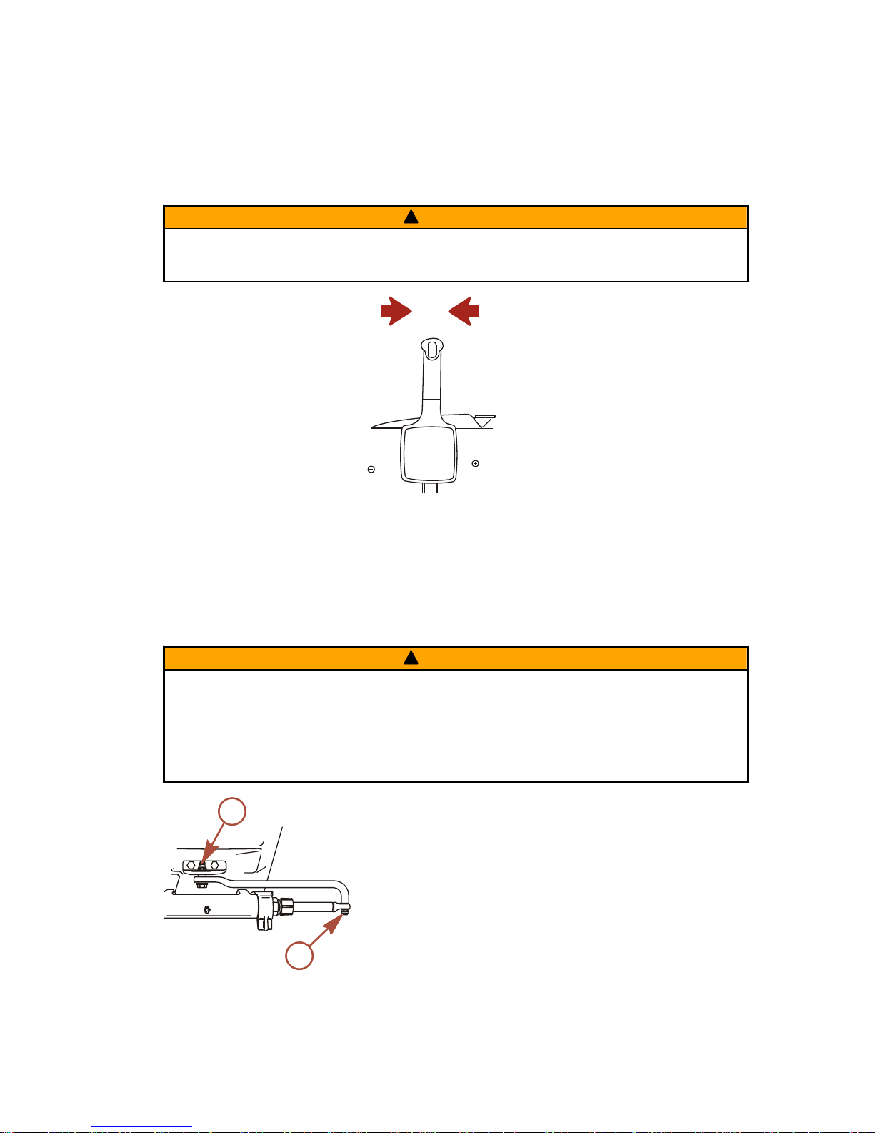
Throttle Grip Friction Adjustment ‑ Tiller Handle Models
Throttle grip friction knob ‑ Turn friction knob to set and maintain the throttle at
desired speed. Turn knob clockwise to tighten friction and turn knob
counterclockwise to loosen friction.
a - Loosen friction
b - Tighten friction
Steering Friction Adjustment ‑ Tiller Handle Models
NOTE: Steering friction adjustment is only provided on models with tiller
handles.
Adjust this lever to achieve the desired steering friction (drag) on the tiller
handle. Move lever to the left to tighten friction or move to the right to loosen
friction.
NOTE: To maintain proper adjustment, the locknut located on top of the
steering friction lever pivot shaft can be tightened.
a - Tighten friction
b - Loosen friction
c - Locknut
!
WARNING
Insufficient friction adjustment can cause serious injury or death due to loss
of boat control. When setting the friction adjustment, maintain sufficient
steering friction to prevent the outboard from steering into a full turn if the
tiller handle is released.
a
b
19807
a
b
c
26811
FEATURES AND CONTROLS
eng 29
Page 40

Replaceable Jet Drive Shear Key
The jet drive is equipped with a shear key to protect it in the event of a lodged
impeller. The shear key can be reached by removing the water intake housing
and impeller.
29174
FEATURES AND CONTROLS
30 eng
Page 41

Important Daily Inspection Before Each Use
Any outboard mounted on the boat must have the mounting hardware
inspected and checked to ensure that the hardware has not become loose. A
decal on the transom bracket reminds the owner to check the fasteners
securing the outboard to the transom before each use.
51985
Decal on the transom bracket
Prestarting Check List
Operator knows safe navigation, boating, and operating procedures.
An approved personal flotation device of suitable size for each person
aboard and readily accessible (it is the law).
A ring type life buoy or buoyant cushion designed to be thrown to a
person in the water.
Know your boats maximum load capacity. Look at the boat capacity plate.
Fuel supply OK.
Oil supply (oil injection) OK.
Ensure the boat drain plug is installed.
Arrange passengers and load in the boat so the weight is distributed
evenly and everyone is seated in a proper seat.
Tell someone where you are going and when you expect to return.
It is illegal to operate a boat while under the influence of alcohol or drugs.
Know the waters and area you will be boating; tides, currents, sand bars,
rocks, and other hazards.
Make inspection checks listed in Maintenance ‑ Inspection and
Maintenance Schedule.
Check steering for free operation.
OPERATION
eng 31
Page 42

Check for debris around the rudder and reverse gate which may jam or
hinder operation.
Before launching, examine the jet drive water intake for obstructions
which may prevent pumping of water.
Ensure the driveshaft bearing on the jet drive is lubricated.
Operating in Freezing Temperatures
If there is a chance of ice forming on the water, the jet drive should be removed
and drained completely of water. If ice should form at the water level inside the
outboard driveshaft housing, it will block water flow to the engine causing
possible damage. Do not start the engine until the ice is clear.
Operating in Saltwater or Polluted Water
If the boat is kept moored in the water, always tilt the outboard so the water
intake is completely out of the water (except in freezing temperatures) when not
in use.
Wash down the outboard exterior and flush out the exhaust outlet of the jet
drive with fresh water after each use. Each month, spray Mercury Precision or
Quicksilver Corrosion Guard on external metal surfaces.
NOTE: Do not spray on corrosion control anodes as this will reduce the
effectiveness of the anodes.
Operating in Shallow Water
The life of the impeller and water intake can be greatly increased by avoiding
the intake of sand and gravel. The intake suction will act like a dredge when the
water intake comes close to the bottom. It is better to stop the engine and drift
up to shore when landing, and to shove off with an oar when leaving. The
engine can idle through areas of water less than 61 cm (2 ft) deep, but there
should be more than 61 cm (2 ft) of water under the boat when increasing
speed to reach full plane.
Once the boat is on plane, the boat speed will prevent the ingestion of gravel
and other debris from the bottom. The suction is still present, but the water
intake passes too quickly over the bottom to allow debris to be drawn into the
water intake.
When boating through shallow water areas, choose a course of travel that
avoids sharp rocks and other underwater obstacles that could damage the
boat. Running the boat through these areas on full plane may be helpful as the
boat will be riding higher in the water. If the boat gets stuck on the bottom,
immediately stop the engine and move the boat to deeper water.
How the Jet Drive Operates
A jet driven boat has substantially different handling characteristics compared
to a propeller driven boat. It is recommended that the operator adjusts to these
characteristics by experimenting in open water at both high and low speeds.
OPERATION
32 eng
Page 43

The driveshaft driven impeller draws water up through the water intake and
then directs it at a high pressure through the water outlet nozzle to create
forward thrust. To obtain reverse, the reverse gate moves over the outlet
nozzle to direct the water in the opposite direction.
a - Water intake
b - Water outlet nozzle
c - Reverse gate
When the jet drive is in neutral, the impeller continues to rotate. However, the
reverse gate is positioned so that some of the forward thrust is diverted to
create reverse thrust. This approximate balancing of forward and reverse thrust
will minimize any boat movement. Because the impeller is always rotating and
creating thrust when the engine is running, the boat may tend to move slowly
forward or backward. This is normal for a direct‑drive jet driven boat. The
operator should be aware of this and use caution whenever the engine is
running.
!
WARNING
Avoid injury resulting from contacting the rotating impeller or having hair,
clothing, or loose objects drawn into the water intake and wrapping around
the impeller shaft. Stay away from the water intake and never insert an object
into the water intake or water outlet nozzle when the engine is running.
The jet drive is always drawing water into the housing when the engine is
running. Do not operate the jet drive with the grate removed from the water
intake. Keep hands, feet, hair, loose clothing, life jackets, etc., away from the
water intake. Never insert an object into the water intake or water outlet nozzle
when the engine is running.
a
c
b
29022
OPERATION
eng 33
Page 44

Stopping the Boat in an Emergency
A jet powered boat has emergency stopping capability unique to this form of
propulsion.
!
WARNING
Using the emergency stopping capability of a jet drive unit will slow down the
boat in an emergency. However, sudden stopping may cause the occupants
of the boat to be thrown forward or out of the boat resulting in serious injury
or death. Use caution when performing the emergency stopping procedure,
and be sure to practice in a safe area.
In an emergency, putting the jet outboard into reverse and applying reverse
throttle can rapidly slow down the boat and reduce stopping distance. However,
such a maneuver may cause occupants in the boat to be thrown forward or
possibly out of the boat.
Steering the Boat
The jet drive is dependent on water jet thrust for steering the boat. If the water
jet thrust should ever stop (water blockage, engine stops, etc.), the boat will
slow to a stop. However, while slowing there will be a reduced ability to steer
the boat.
!
WARNING
Steering the vessel in a tight turn can result in loss of boat control. In some
cases, the boat can spin out or roll over, causing serious injury or death.
Avoid steering beyond the capabilities of the vessel, especially at high
speeds.
!
WARNING
A loss or reduction in water jet thrust will directly affect boat directional
control, and may result in property damage, personal injury, or death. Boat
directional control can also be substantially reduced or lost altogether by a
sudden loss of power such as running out of gas, quickly backing off the
throttle, turning off the ignition switch, activating the lanyard stop switch, or
plugging the water intake to the jet pump. Use caution when maneuvering at
high speeds in areas where debris (weeds, logs, gravel, etc.) could be picked
up into the jet drive. The ability to take evasive action is dependent on
sufficient water jet thrust to control the boat.
While steering the boat at engine speeds above idle, the boat will respond
quickly; but, due to the relatively flat‑bottom hulls and lack of a gearcase in the
water, the boat will tend to skid on turns. Turns must be started early and use
sufficient power to maintain steering control.
OPERATION
34 eng
Page 45

Mooring the Boat
Be sure to tilt the jet drive out of the water when the boat is pulled onto a beach
or tied to a dock in shallow water. Failure to do this may cause the water intake
housing to fill with sand or debris and could prevent the outboard from cranking
over for starting.
Water Intake Blockage
!
WARNING
A rotating impeller could cause injury if contact is made with hands, clothing,
or tools. To avoid injury, keep hands and clothing away from the inlet or
outlet of the jet drive, regardless of whether the boat is in the water. Secure
tools and loose items to avoid being struck by projectiles as a result of
contact with the rotating impeller, and to prevent damage to the impeller.
A large amount of debris being drawn into the water intake may result in a loss
of power. Intake suction holding debris against the grate will result in restricted
water flow. Shutting the engine off may allow the debris to fall off the intake
grate allowing full power to be restored. If debris does not fall off the intake
grate, the engine must be shut off and debris physically removed from the
grate.
Clearing A Lodged Impeller
!
WARNING
Rotating the flywheel to free a lodged impeller can accidentally start the
engine, resulting in serious injury or death. Always turn the ignition key or
lanyard stop switch to the "OFF" position and remove all spark plug leads
from the spark plugs.
It is possible for debris to lodge between the impeller and jet housing wall,
especially after the engine has been stopped. This will lock the driveshaft and
will prevent the engine from being able to crank over for starting. Following are
steps for dislodging the impeller.
1. Position the lanyard stop switch to the "OFF" position.
2. Remove the spark plug leads to prevent the engine from accidentally
starting.
3. Remove the flywheel or rewind cover and rotate the engine flywheel
counterclockwise.
If this does not dislodge the impeller, it will be necessary to remove the six
screws and water intake housing.
OPERATION
eng 35
Page 46

Pre‑Starting Instructions
1. Check the engine oil level.
28525
2. Ensure that the driveshaft bearing on the jet drive is lubricated. Refer to
Maintenance ‑ Lubrication Points.
28664
Engine Break‑in Procedure
IMPORTANT: Failure to follow the engine break‑in procedures can result in
poor performance throughout the life of the engine and can cause engine
damage. Always follow break‑in procedures.
1. For the first hour of operation, run the engine at varied throttle settings up
to 3500 RPM or at approximately half throttle.
2. For the second hour of operation, run the engine at varied throttle settings
up to 4500 RPM or at three‑quarter throttle, and during this period of time,
run it at full throttle for approximately one minute every ten minutes.
3. For the next eight hours of operation, avoid continuous operation at full
throttle for more than five minutes at a time.
Starting the Engine ‑ Remote Control Models
Before starting, read the pre‑starting check list, special operating instructions,
and engine break‑in procedure in the Operation section.
OPERATION
36 eng
Page 47

NOTICE
Failure to provide sufficient cooling water will damage the water pump and
cause the engine to overheat. Never start or operate the engine without the
intake housing in the water.
1. Open fuel tank vent screw (in filler cap) on manual venting type fuel tanks.
19748
2. Position the fuel line primer bulb so the arrow on the side of the bulb is
pointing up. Squeeze the fuel line primer bulb several times until it feels
firm.
27348
3.
Set the lanyard stop switch to "RUN" position. Refer to General
Information ‑ Lanyard Stop Switch.
19791
OPERATION
eng 37
Page 48

4. Shift outboard to neutral ("N") position.
N
26838
5. Move the throttle‑only lever to the fully closed position or press the
throttle‑only button.
a - Fully closed position
b - Maximum fast idle speed position
6. Starting a flooded engine ‑ Advance the throttle‑only lever or control
handle to the maximum throttle‑only position and continue to crank the
engine for starting. Immediately reduce engine speed after engine starts.
7. Turn ignition key to the "START" position. If the engine fails to start in ten
seconds, return the key to the "ON" position, wait 30 seconds and try
again.
19804
a
b
a
b
26840
OPERATION
38 eng
Page 49

8. After engine starts, check for a steady stream of water flowing out of the
water pump indicator hole.
28521
IMPORTANT: If no water is coming out of the water pump indicator hole, stop
engine and check cooling water intake for obstruction. No obstruction may
indicate a water pump failure or blockage in the cooling system. These
conditions will cause the engine to overheat. Have the outboard checked by
your dealer. Operating the engine while overheated will cause engine damage.
WARMING UP ENGINE
Before beginning operation, allow the engine to warm up at idling speed for
three minutes.
Starting the Engine ‑ Tiller Handle Models
Before starting, read the pre‑starting check list, special operating instructions,
and engine break‑in procedure in the Operation section.
NOTICE
Failure to provide sufficient cooling water will damage the water pump and
cause the engine to overheat. Never start or operate the engine without the
intake housing in the water.
1. Open fuel tank vent screw (in filler cap) on manual venting type fuel tanks.
19748
OPERATION
eng 39
Page 50

2. Connect the remote fuel line to the outboard. Make sure the connector is
snapped into place.
28526
3. Position the fuel line primer bulb so the arrow on the side of the bulb is
pointing up. Squeeze the fuel line primer bulb several times until it feels
firm.
27348
4.
Set the lanyard stop switch to "RUN" position. Refer to General
Information ‑ Lanyard Stop Switch.
19791
5. Shift outboard to neutral ("N") position.
N
28522
6. Set the throttle grip to start position.
OPERATION
40 eng
Page 51

7. Starting a flooded engine ‑ Set the throttle grip to half‑way position.
a - Start position
b - Half‑way position
8. Turn the ignition key to the "START" position. If the engine fails to start in
ten seconds, return the key to the "ON" position, wait 30 seconds and try
again.
19804
!
WARNING
Rapid acceleration can result in serious injury or death from being thrown
within or out of the boat. Decrease engine speed before shifting into gear.
9. Check for a steady stream of water flowing out of the water pump
indicator hole.
28521
IMPORTANT: If no water is coming out of the water pump indicator hole, stop
engine and check cooling water intake for obstruction. No obstruction may
indicate a water pump failure or blockage in the cooling system. These
conditions will cause the engine to overheat. Have the outboard checked by
your dealer. Operating the engine while overheated may cause serious engine
damage.
WARMING UP ENGINE
Before beginning operation, allow the engine to warm up at idling speed for
three minutes.
ART
0%100
START
ST
0%100
START
START
a
b
19799
OPERATION
eng 41
Page 52

Gear Shifting
IMPORTANT: Observe the following:
•
Never shift outboard into gear unless engine speed is at idle.
• Your outboard has three gear shift positions to provide operation: forward,
neutral (out of gear), and reverse.
F
N
R
F
N
R
28523
• Remote control models ‑ When shifting, always stop at the neutral
position and allow the engine speed to return to idle.
26779
• Tiller handle models ‑ Reduce the engine speed to idle before shifting.
26842
• Always shift the outboard into gear with a quick motion.
• After shifting the outboard into gear, advance the remote control lever or
rotate the throttle grip (tiller handle) to increase speed.
OPERATION
42 eng
Page 53

Stopping the Engine
1.
Remote control models ‑ Reduce the engine speed and shift the
outboard to neutral position. Turn the ignition key to "OFF" position.
26843
2.
Tiller handle models ‑ Reduce the engine speed and shift the outboard
to neutral position. Push in the engine stop button or turn the ignition key
to "OFF" position.
26776
Emergency Starting
If the starter system fails, use the spare starter rope (provided) and follow
procedure.
NOTE: EFI models ‑ Engine must have a fully charged battery to start the
engine.
1. Remove flywheel cover or manual starter assembly.
26844
OPERATION
eng 43
Page 54

2. Shift outboard to neutral ("N") position.
N
N
28528
!
WARNING
The neutral‑speed‑protection device is inoperative when starting the engine
with the emergency starter rope. Set the engine speed at idle and the gear
shift in neutral to prevent the outboard from starting in gear.
3. Electric start models ‑ Turn the ignition key to "ON" position.
26846
!
WARNING
High voltage is present any time the key is turned on, especially when
starting or operating the engine. Do not touch ignition components or metal
test probes and stay clear of spark plug leads when performing live tests.
!
WARNING
The exposed moving flywheel can cause serious injury. Keep your hands,
hair, clothing, tools, and other objects away from engine when starting or
running the engine. Do not attempt to reinstall the flywheel cover or top
cowl when engine is running.
4. Place the starter rope knot into the flywheel notch and wind the rope
clockwise around the flywheel.
OPERATION
44 eng
Page 55

5. Pull the starter rope to start the engine.
26848
OPERATION
eng 45
Page 56

Outboard Care
To keep your outboard in the best operating condition, it is important that your
outboard receive the periodic inspections and maintenance listed in the
Inspection and Maintenance Schedule. We urge you to keep it maintained
properly to ensure the safety of you and your passengers, and retain its
dependability.
Record maintenance performed in the Maintenance Log at the back of this
book. Save all maintenance work orders and receipts.
SELECTING REPLACEMENT PARTS FOR YOUR OUTBOARD
We recommend using original Mercury Precision or Quicksilver replacement
parts and Genuine Lubricants.
EPA Emissions Regulations
All new outboards manufactured by Mercury Marine are certified to the United
States Environmental Protection Agency, as conforming to the requirements of
the regulations for the control of air pollution from new outboard motors. This
certification is contingent on certain adjustments set to factory standards. For
this reason, the factory procedure for servicing the product must be strictly
followed and, wherever practicable, returned to the original intent of the design.
Maintenance, replacement, or repair of the emission control devices and
systems may be performed by any marine spark ignition (SI) engine
repair establishment or individual.
MAINTENANCE
46 eng
Page 57

EMISSION CERTIFICATION LABEL
An emission certification label, showing emission levels and engine
specifications directly related to emissions, is placed on the engine at the time
of manufacture.
a - Idle speed
b - Engine horsepower
c - Piston displacement
d - Engine power ‑ kilowatts
e - Date of manufacture
f - Family number
g - Regulated emission limit for the engine family
h - Regulated emission limit for the engine family
i - Recommended spark plug and gap
j - Percent of fuel line permeation
OWNER RESPONSIBILITY
The owner/operator is required to have routine engine maintenance performed
to maintain emission levels within prescribed certification standards.
The owner/operator is not to modify the engine in any manner that would alter
the horsepower or allow emission levels to exceed their predetermined factory
specifications.
Inspection and Maintenance Schedule
DAILY CHECKS
• Check the engine oil level
• Check the lanyard stop switch
• Inspect the fuel system for leaks
• Inspect the engine tightness on the transom
• Check the steering system for binding
• Check the propeller for damage
• Inspect the hydraulic steering fittings and hoses for leaks or signs of
damage, if equipped
SPARK PLUG:
GAP:
EMISSION CONTROL
INFORMATION
THIS ENGINE CONFORMS TO
EMISSION REGULATIONS FOR SPARK IGNITION MARINE ENGINES
CALIFORNIA AND U.S. EPA
REFER TO OWNERS MANUAL FOR REQUIRED MAINTENANCE,
SPECIFICATIONS, AND ADJUSTMENTS
IDLE SPEED (in gear):
FAMILY:
HC+NOx:FEL:
LOW PERM/HIGH PERM:
g/kWh
hp
L
e
d
c
b
a
f
g
h
i
HC+NOx:FEL:
g/kWh
hp
L
CO FEL:
g/kWh
kw
g/kWh
j
43210
MAINTENANCE
eng 47
Page 58

• Check the hydraulic steering fluid level, if equipped
AFTER EACH USE
• Wash the power package exterior with fresh water
• Flush the outboard cooling system, saltwater or brackish water only
ANNUALLY OR 100 HOURS
• Grease the engine, if applicable
• Change the engine oil and filter, if equipped
• Inspect the thermostat, saltwater or brackish water only
• Add Quickleen to the fuel tank, once per year, per engine
• Apply anti‑seize to the spark plug threads
• Replace the gear lubricant
• Inspect the corrosion control anodes
• Replace all filters on the suction side of the fuel system—dealer item
• Lubricate the driveshaft splines—dealer item
• Lubricate the propeller shaft splines—dealer item
• Check the tightness on all the fasteners—dealer item
• Check the torque of the outboard mounting hardware—dealer item
• Check the battery condition and tightness of the battery cable connection
—dealer item
THREE YEARS OR 300 HOURS
• Replace the spark plugs
• Replace the water pump impeller—dealer item
• Inspect the carbon fiber reeds—dealer item
• Inspect the wire harness connectors—dealer item
• Check the remote control cable adjustment, if applicable—dealer item
• Replace the high‑pressure fuel filter—dealer item
• Replace the accessory drive belt—dealer item
• Check the power trim fluid level—dealer item
• Inspect the engine motor mounts—dealer item
Flushing the Cooling System
Flush the internal water passages of the outboard with fresh water after each
use in salt, polluted, or muddy water. This will help prevent a buildup of
deposits from clogging the internal water passages.
IMPORTANT: The engine must be run during flushing in order to open the
thermostat and circulate water through the water passages.
MAINTENANCE
48 eng
Page 59

!
WARNING
Rotating propellers can cause serious injury or death. Never operate the boat
out of the water with a propeller installed. Before installing or removing a
propeller, place the drive unit in neutral and engage the lanyard stop switch
to prevent the engine from starting. Place a block of wood between the
propeller blade and the anti‑ventilation plate.
1. Place the outboard in either the operating position (vertical) or in a tilted
position.
2.
Remove the propeller. Refer to Propeller Replacement.
3. Thread a water hose into the rear fitting. Partially open the water tap (1/2
maximum). Do not open the water tap all the way as this allows a high
pressure flow of water.
IMPORTANT: Do not run engine above idle when flushing.
4. Shift the outboard into neutral. Start the engine and flush the cooling
system for at least five minutes. Keep the engine speed at idle.
5. Stop the engine. Turn off the water and remove the hose. Reinstall the
propeller.
28518
MAINTENANCE
eng 49
Page 60

Top Cowl Removal and Installation
REMOVAL
Pull out the rear lock lever and remove the top cowl.
28439
INSTALLATION
1. Lower the top cowl over the engine.
2. Bring the front of the cowl down first and engage the front hook. Lower the
cowl into its seated position and apply downward pressure to the back of
the cowl to lock it in place. Gently pull up on the back of cowl to make
sure it is securely fastened.
28445
Exterior Care
Your outboard is protected with a durable baked enamel finish. Clean and wax
often using marine cleaners and waxes.
Battery Inspection
The battery should be inspected at periodic intervals to ensure proper engine
starting capability.
IMPORTANT: Read the safety and maintenance instructions which accompany
your battery.
1. Turn off the engine before servicing the battery.
MAINTENANCE
50 eng
Page 61

2. Ensure the battery is secure against movement.
3. Battery cable terminals should be clean, tight, and correctly installed.
Positive to positive and negative to negative.
4. Ensure the battery is equipped with a nonconductive shield to prevent
accidental shorting of battery terminals.
Fuel System
!
WARNING
Fuel is flammable and explosive. Ensure that the key switch is off and the
lanyard is positioned so that the engine cannot start. Do not smoke or allow
sources of spark or open flame in the area while servicing. Keep the work
area well ventilated and avoid prolonged exposure to vapors. Always check
for leaks before attempting to start the engine, and wipe up any spilled fuel
immediately.
Before servicing any part of the fuel system, stop the engine and disconnect
the battery. Drain the fuel system completely. Use an approved container to
collect and store the fuel. Wipe up any spillage immediately. Material used to
contain spillage must be disposed of in an approved receptacle. Any fuel
system service must be performed in a well‑ventilated area. Inspect any
completed service work for sign of fuel leakage.
FUEL LINE INSPECTION
Visually inspect the fuel line and primer bulb for cracks, swelling, leaks,
hardness, or other signs of deterioration or damage. If any of these conditions
are found, the fuel line or primer bulb must be replaced.
ENGINE FUEL FILTER
Check the fuel filter for water accumulation or sediment. If water is in the fuel,
remove the sight bowl and drain the water. If the filter appears to be
contaminated, remove and replace.
REMOVAL
1. Read the preceding fuel system servicing information and warning.
2. Pull out the filter assembly from the mount. Hold onto the cover to prevent
it from turning and remove the sight bowl. Empty contents into an
approved container.
MAINTENANCE
eng 51
Page 62

3. Inspect the filter element. If replacement is necessary, replace the filter
assembly.
a - Cover
b - Filter element
c - O‑ring seal
d - Sight bowl
INSTALLATION
IMPORTANT: Visually inspect for fuel leakage from the filter by squeezing the
primer bulb until firm, forcing fuel into the filter.
1. Push the filter element into the cover.
2. Place the O‑ring seal into its proper position on the sight bowl and screw
the sight bowl hand‑tight into the cover.
3. Push the filter assembly back into the mount.
Steering Link Rod Fasteners
IMPORTANT: The steering link rod that connects the steering cable to the
engine must be fastened using special washer head bolt ("e" ‑ Part Number
10‑856680) and self‑locking nylon insert locknuts ("b" and "d" ‑ Part Number
11‑826709113). These locknuts must never be replaced with common nuts
(nonlocking) as they will work loose and vibrate off, freeing the link rod to
disengage.
a
b
c
d
28414
MAINTENANCE
52 eng
Page 63

!
WARNING
Improper fasteners or improper installation procedures can result in
loosening or disengagement of the steering link rod. This can cause a
sudden, unexpected loss of boat control, resulting in serious injury or death
due to occupants being thrown within or out of the boat. Always use required
components and follow instructions and torque procedures.
a - Spacer (12‑71970)
b - Nylon insert locknut (11‑826709113)
c - Flat washer (2)
d - Nylon insert locknut (11‑826709113)
e - Special washer head bolt (10‑856680)
Description Nm lb‑in. lb‑ft
Nylon insert locknut "b" 27 20
Nylon insert locknut "d"
Tighten until it seats, then back off 1/4
turn
Special washer head bolt 27 20
Assemble steering link rod to steering cable with two flat washers and nylon
insert locknut. Tighten locknut until it seats, then back nut off 1/4 turn.
Assemble steering link rod to engine with special washer head bolt, locknut,
and spacer. First torque bolt, then locknut to specification.
Corrosion Control Anode
Your outboard has corrosion control anodes at different locations. An anode
helps protect the outboard against galvanic corrosion by sacrificing its metal to
be slowly corroded instead of the outboard metals.
a
b
e
d
c
26895
MAINTENANCE
eng 53
Page 64

Each anode requires periodic inspection, especially in saltwater which will
accelerate the erosion. To maintain this corrosion protection, always replace
the anode before it is completely eroded. Never paint or apply a protective
coating on the anode as this will reduce effectiveness of the anode.
One anode is installed on the bottom of the transom bracket assembly and the
other anode is located on the water intake housing.
a - Water intake housing anode
b - Transom bracket anode
Spark Plug Inspection and Replacement
!
WARNING
Damaged spark plug boots may emit sparks that can ignite fuel vapors under
the engine cowl, resulting in serious injury or death from a fire or explosion.
To avoid damaging the spark plug boots, do not use any sharp object or
metal tool to remove the spark plug boots.
1. Remove the spark plug boots. Twist the rubber boots slightly and pull off.
26899
a
24838
b
28703
MAINTENANCE
54 eng
Page 65

2. Remove the spark plugs to inspect. Replace spark plug if electrode is
worn or the insulator is rough, cracked, broken, blistered, or fouled.
26946
3. Set the spark plug gap to specification.
26947
Spark Plug
Spark plug gap 1.0 mm (0.040 in.)
4. Before installing spark plugs, clean off any dirt on the spark plug seats.
Install plugs finger‑tight, and then tighten 1/4 turn or torque to
specifications.
Description
Nm lb‑in. lb‑ft
Spark plug 27 20
Steering Pull Adjustment
The steering on some boats will have the tendency to pull towards starboard.
This pulling condition can be corrected by using a pliers and bending the ends
of the exhaust fins 1.5 mm (1/16 in.) toward the starboard side of the outboard.
a - Exhaust fins
a
29573
MAINTENANCE
eng 55
Page 66

Worn/Dull Impeller
The intake of gravel through the pump can round off and wear the leading
edges of the impeller. Some conditions that could be experienced from a worn/
dull impeller are as follows:
• Noticeable performance loss, especially on acceleration
• Difficulty getting the boat on plane
• An increase in engine RPM at wide‑open throttle
IMPORTANT: Do not sharpen or alter the top side lifting angle.
Check the impeller blades occasionally for damage. Use a flat file to sharpen
the leading edges. Sharpen to a 0.8 mm (1/32 in.) radius by removing material
from bottom side only.
a - Leading edge
b - Top side lifting angle
Impeller Clearance Adjustment
The impeller should be adjusted so there is approximately 0.8 mm (0.03 in.)
clearance between the impeller edge and liner. Operating the jet drive in waters
that contain sand and gravel can cause wear to the impeller blades, and the
clearance will start to exceed 0.8 mm (0.03 in.).
As the blades wear, shims located in the stack outside of the impeller can be
transferred behind the impeller. This will move the impeller further down into
the tapered liner to reduce the clearance.
a - Shims
b - Clearance between impeller
edge and liner
a
b
29079
a
b
29080
MAINTENANCE
56 eng
Page 67

Check the impeller clearance by sliding a feeler gauge through the intake grate
and measure the clearance between the impeller edge and liner.
Fuse Replacement
IMPORTANT: Always carry spare fuses.
The electrical wiring circuits on the outboard are protected from overload by
fuses in the wiring. If a fuse is blown, try to locate and correct the cause of the
overload. If the cause is not found, the fuse may blow again.
Open the fuse holder and look at the silver colored band inside the fuse. If the
band is broken, replace the fuse. Replace the fuse with a new fuse of the same
rating.
a - Ignition coil circuit—20 amp
b - Fuel pump/idle air control/fuel injector circuits—20 amp
c - Voltage regulator—25 amp
d - Main power relay/accessories/remote control—15 amp
e - Spare—20 amp
f - Good fuse
g - Blown fuse
a
b
c
d
e
f
g
61074
MAINTENANCE
eng 57
Page 68

Timing Belt Inspection
Inspect the timing belt and have it replaced by an authorized dealer if any of the
following conditions are found.
• Cracks in the back of the belt or in the base of the belt teeth.
• Excessive wear at the roots of the cogs.
• Rubber portion swollen by oil.
• Belt surfaces roughened.
• Signs of wear on edges or outer surfaces of belt.
26958
Lubrication Points
1. Lubricate the following with Quicksilver or Mercury Precision 2‑4‑C with
PTFE.
Tube Ref
No.
Description Where Used Part No.
95
2-4-C with PTFE Driveshaft bearing 92-802859A 1
IMPORTANT: It is important not to use a general all‑purpose grease for this
bearing. The lubricant recommended is a water‑resistant grease of the proper
consistency for this application. If a substitute is used, be sure that it is
water‑resistant.
• Driveshaft bearing
i. Pull vent hose off of the grease fitting.
ii. Pump in grease through the grease fitting, using the grease gun
provided, until excess grease starts to exit the vent hose.
MAINTENANCE
58 eng
Page 69

iii. Connect the vent hose onto the grease fitting after greasing.
a - Grease fitting
b - Vent hose
NOTE: After 30 hours of operation, pump in extra grease to purge out any
moisture. Visually inspecting the purged grease at this time will give an
indication of conditions inside the bearing housing. A gradual increase in
moisture content indicates seal wear. If the grease begins to turn a dark, dirty
gray color, the driveshaft bearing and seals should be inspected and replaced
if necessary. Some discoloration of the grease is normal during the break‑in
period on a new set of seals.
2. Lubricate the following with Quicksilver or Mercury Precision Lubricants
2‑4‑C with PTFE.
Tube Ref
No.
Description Where Used Part No.
95
2-4-C with PTFE
Tilt support lever, swivel bracket, tilt
tube, steering cable grease fitting
92-802859A 1
• Tilt support lever ‑ Lubricate through fitting.
• Swivel bracket ‑ Lubricate through fitting.
a - Tilt support lever
b - Swivel bracket
a
b
28691
a
b
28466
MAINTENANCE
eng 59
Page 70

• Tilt tube ‑ Lubricate through fitting.
28461
• Co‑pilot shaft (tiller handle models) ‑ Lubricate through fitting. Move
the steering friction lever back and forth while lubricating.
28823
!
WARNING
Incorrect cable lubrication can cause hydraulic lock, leading to serious
injury or death from loss of boat control. Completely retract the end of the
steering cable before applying lubricant.
• Steering cable grease fitting (if equipped) ‑ Rotate steering wheel to
fully retract the steering cable end into the outboard tilt tube. Lubricate
through fitting.
a - Fitting
b - Steering cable end
b
a
28468
MAINTENANCE
60 eng
Page 71

3. Lubricate the following with lightweight oil.
• Steering link rod pivot points ‑ Lubricate points.
28471
Checking Power Trim Fluid
1. Tilt the outboard to the full up position and engage the tilt support lock.
28474
2. Remove the fill cap and check the fluid level. The fluid level should be
even with the bottom of the fill hole. Add Quicksilver or Mercury Precision
Lubricants Power Trim and Steering Fluid. If not available, use automotive
automatic transmission fluid (ATF).
28476
Tube Ref
No.
Description Where Used Part No.
114
Power Trim and
Steering Fluid
Power trim reservoir 92-858074K01
MAINTENANCE
eng 61
Page 72

Changing Engine Oil
ENGINE OIL CAPACITY
Capacity Fluid Type
Engine oil
3.0 Liter
(3 U.S. Quarts)
Mercury Precision Parts or Quicksilver Synthetic
Blend 25W‑40 4‑Stroke Outboard Oil
Mercury Precision Parts or Quicksilver 10W‑30
4‑Stroke Outboard Oil
OIL CHANGING PROCEDURE
1. Tilt the outboard up to the trailer position.
2. Turn the steering on the outboard so that the drain hole is facing
downward. Remove drain plug and drain engine oil into an appropriate
container. Lubricate the seal on the drain plug with oil and reinstall.
a - Drain plug
CHANGING OIL FILTER
1. Place a rag or towel below the oil filter to absorb any spilled oil.
2. Unscrew the old filter by turning the filter to the left.
3. Clean the mounting base. Apply a film of clean oil to the filter gasket. Do
not use grease
a
28633
MAINTENANCE
62 eng
Page 73

4. Screw the new filter on until the gasket contacts the base, then tighten 3/4
to 1 turn.
28417
OIL FILLING
1. Remove the oil fill cap and add oil to the proper operating level.
2. Idle the engine for five minutes and check for leaks. Stop the engine and
check the oil level on the dipstick. Add oil if necessary.
a - Oil fill cap
Submerged Outboard
A submerged outboard will require service within a few hours by an authorized
dealer once the outboard is recovered from the water. This immediate attention
by a servicing dealer is necessary once the engine is exposed to the
atmosphere to minimize internal corrosion damage to the engine.
a
28418
MAINTENANCE
eng 63
Page 74

Storage Preparation
The major consideration in preparing your outboard for storage is to protect it
from rust, corrosion, and damage caused by freezing of trapped water.
The following storage procedures should be followed to prepare your outboard
for out of season storage or prolonged storage (two months or longer).
NOTICE
Without sufficient cooling water, the engine, the water pump, and other
components will overheat and suffer damage. Provide a sufficient supply of
water to the water inlets during operation.
FUEL SYSTEM
IMPORTANT: Gasoline containing alcohol (ethanol or methanol) can cause a
formation of acid during storage and can damage the fuel system. If the
gasoline being used contains alcohol, it is advisable to drain as much of the
remaining gasoline as possible from the fuel tank, remote fuel line, and engine
fuel system.
Fill the fuel tank and engine fuel system with treated (stabilized) fuel to help
prevent formation of varnish and gum. Proceed with the following instructions.
• Portable fuel tank ‑ Pour the required amount of gasoline stabilizer (follow
instructions on container) into the fuel tank. Tip fuel tank back and forth to
mix stabilizer with the fuel.
• Permanently installed fuel tank ‑ Pour the required amount of gasoline
stabilizer (follow instructions on container) into a separate container and
mix with approximately one liter (one quart) of gasoline. Pour this mixture
into the fuel tank.
• Remove the fuel filter sight bowl and empty contents in a suitable
container. Refer to Maintenance ‑ Fuel System for removal and
installation of filter. Add 3 cc (1/2 tsp.) of gasoline stabilizer into the fuel
filter sight bowl and install.
• Place the outboard in water or connect flushing attachment for circulating
cooling water. Run the engine at idle RPM for 15 minutes to fill the engine
fuel system with stabilized fuel.
Protecting External Outboard Components
•
Lubricate all outboard components listed in Maintenance ‑ Inspection
and Maintenance Schedule.
• Touch up any paint nicks. See your dealer for touch‑up paint.
• Spray Quicksilver or Mercury Precision Lubricants Corrosion Guard on
external metal surfaces (except corrosion control anodes).
STORAGE
64 eng
Page 75

Tube Ref
No.
Description Where Used Part No.
120
Corrosion Guard External metal surfaces 92-802878 55
Protecting Internal Engine Components
• Remove the spark plugs and add approximately 30 ml (1 oz.) of engine oil
or inject a five second spray of storage seal into each spark plug hole.
• Rotate the flywheel manually several times to distribute the oil in the
cylinders. Reinstall spark plugs.
• Change the engine oil.
Jet Drive
• Pump extra grease into the jet drive bearing to purge out moisture.
Positioning Outboard for Storage
Store the outboard in an upright (vertical) position. This will allow water to drain
out of the outboard.
Battery Storage
• Follow the battery manufacturer's instructions for storage and charging.
• Remove the battery from the boat and check water level. Charge if
necessary.
• Store the battery in a cool, dry place.
• Periodically check the water level and charge the battery during storage.
STORAGE
eng 65
Page 76

Starter Motor Will Not Crank the Engine (Electric Start Models)
POSSIBLE CAUSES
•
Blown fuse in the starting circuit. Refer to Maintenance section.
• Outboard is not shifted to neutral position.
• Weak battery or battery connections are loose or corroded.
• Ignition key switch failure.
• Wiring or electrical connection faulty.
• Starter motor or starter solenoid failure.
Engine Will Not Start
POSSIBLE CAUSES
• Lanyard stop switch not in "RUN" position.
•
Incorrect starting procedure. Refer to Operation section.
• Old or contaminated gasoline.
•
Engine flooded. Refer to Operation section.
• Fuel is not reaching the engine.
a. Fuel tank is empty.
b. Fuel tank vent not open or restricted.
c. Fuel line is disconnected or kinked.
d. Primer bulb not squeezed.
e. Primer bulb check valve is faulty.
f.
Fuel filter is obstructed. Refer to Maintenance section.
g. Fuel pump failure.
h. Fuel tank filter obstructed.
•
Blown fuse. Refer to Maintenance section.
• Ignition system component failure.
•
Spark plugs fouled or defective. Refer to Maintenance section.
Engine Runs Erratically
POSSIBLE CAUSES
•
Guardian System activated. Refer to Features and Controls ‑ Warning
System.
•
Spark plugs fouled or defective. Refer to Maintenance section.
• Incorrect setup and adjustments.
• Fuel is being restricted to the engine.
a.
Engine fuel filter is obstructed. Refer to Maintenance section.
b. Fuel tank filter obstructed.
TROUBLESHOOTING
66 eng
Page 77

c. Stuck anti‑siphon valve located on permanently built‑in type fuel tanks.
d. Fuel line is kinked or pinched.
• Fuel pump failure.
• Ignition system component failure.
• Fuel injection component failure (EFI Models).
Engine Overspeed (Excessive RPM)
POSSIBLE CAUSES
• Outboard mounted too high on the transom.
• Worn jet pump impeller or liner.
• Incorrect jet pump impeller clearance adjustment.
• Tilting the outboard out beyond a vertical position.
• Cavitation of the impeller due to rough water or obstruction in the boat
hull.
• Blockage of the water intake.
Performance Loss
POSSIBLE CAUSES
• Throttle not fully open.
• Damaged impeller.
• Incorrect engine timing, adjustments, or setup.
• Boat overloaded or load improperly distributed.
• Excessive water in bilge.
• Boat bottom is dirty or damaged.
Battery Will Not Hold Charge
POSSIBLE CAUSES
• Battery connections are loose or corroded.
• Low electrolyte level in battery.
• Worn out or inefficient battery.
• Excessive use of electrical accessories.
• Defective rectifier, alternator, or voltage regulator.
TROUBLESHOOTING
eng 67
Page 78

Local Repair Service
Always return your outboard to your local authorized dealer should the need for
service arise. Only he has the factory trained mechanics, knowledge, special
tools, equipment, and genuine parts and accessories to properly service your
engine should the need occur. He knows your engine best.
Service Away from Home
If you are away from your local dealer and the need arises for service, contact
the nearest authorized dealer. Refer to the Yellow Pages of the telephone
directory. If, for any reason, you cannot obtain service, contact the nearest
Mercury Marine Service Office.
Parts and Accessories Inquiries
All inquiries concerning genuine replacement parts and accessories should be
directed to your local authorized dealer. The dealer has the necessary
information to order parts and accessories for you. When inquiring about parts
and accessories, the dealer requires the model and serial number to order the
correct parts.
Service Assistance
LOCAL REPAIR SERVICE
If you need service for your Mercury‑outboard‑powered boat, take it to your
authorized dealer. Only authorized dealers specialize in Mercury products and
have factory‑trained mechanics, special tools and equipment, and genuine
Quicksilver parts and accessories to properly service your engine.
NOTE: Quicksilver parts and accessories are engineered and built by Mercury
Marine specifically for your power package.
SERVICE AWAY FROM HOME
If you are away from your local dealer and the need arises for service, contact
the nearest authorized dealer. If, for any reason, you cannot obtain service,
contact the nearest Regional Service Center. Outside the United States and
Canada, contact the nearest Marine Power International Service Center.
STOLEN POWER PACKAGE
If your power package is stolen, immediately advise the local authorities and
Mercury Marine of the model and serial numbers and to whom the recovery is
to be reported. This information is maintained in a database at Mercury Marine
to aid authorities and dealers in the recovery of stolen power packages.
ATTENTION REQUIRED AFTER SUBMERSION
1. Before recovery, contact an authorized Mercury dealer.
2. After recovery, immediate service by an authorized Mercury dealer is
required to reduce the possibility of serious engine damage.
OWNER SERVICE ASSISTANCE
68 eng
Page 79

REPLACEMENT SERVICE PARTS
!
WARNING
Avoid fire or explosion hazard. Electrical, ignition, and fuel system
components on Mercury Marine products comply with federal and
international standards to minimize risk of fire or explosion. Do not use
replacement electrical or fuel system components that do not comply with
these standards. When servicing the electrical and fuel systems, properly
install and tighten all components.
Marine engines are expected to operate at or near full throttle for most of their
lives. They are also expected to operate in both fresh and saltwater
environments. These conditions require numerous special parts.
PARTS AND ACCESSORIES INQUIRIES
Direct any inquiries concerning Quicksilver replacement parts and accessories
to your local authorized dealer. The dealer has the necessary information to
order parts and accessories for you if they are not in stock. Only authorized
dealers can purchase genuine Quicksilver parts and accessories from the
factory. Mercury Marine does not sell to unauthorized dealers or retail
customers. When inquiring about parts and accessories, the dealer requires the
engine model and serial numbers to order the correct parts.
RESOLVING A PROBLEM
Satisfaction with your Mercury product is important to your dealer and to us. If
you ever have a problem, question or concern about your power package,
contact your dealer or any authorized Mercury dealership. If you need
additional assistance:
1. Talk with the dealership's sales manager or service manager. Contact the
owner of the dealership if the sales manager and service manager have
been unable to resolve the problem.
2. If your question, concern, or problem cannot be resolved by your
dealership, please contact the Mercury Marine Service Office for
assistance. Mercury Marine will work with you and your dealership to
resolve all problems.
The following information will be needed by the Customer Service:
• Your name and address
• Your daytime telephone number
• The model and serial numbers of your power package
• The name and address of your dealership
• The nature of the problem
OWNER SERVICE ASSISTANCE
eng 69
Page 80

CONTACT INFORMATION FOR MERCURY MARINE CUSTOMER
SERVICE
For assistance, call, fax, or write to the geographic office in your area. Please
include your daytime telephone number with mail and fax correspondence.
United States, Canada
Telephone
English +1 920 929 5040
Français +1 905 636 4751
Mercury Marine
W6250 Pioneer Road
P.O. Box 1939
Fond du Lac, WI 54936-1939
Fax
English +1 920 929 5893
Français +1 905 636 1704
Website www.mercurymarine.com
Australia, Pacific
Telephone +61 3 9791 5822 Brunswick Asia Pacific Group
41–71 Bessemer Drive
Dandenong South, Victoria 3175
Australia
Fax +61 3 9706 7228
Europe, Middle East, Africa
Telephone +32 87 32 32 11 Brunswick Marine Europe
Parc Industriel de Petit-Rechain
B-4800 Verviers,
Belgium
Fax +32 87 31 19 65
Mexico, Central America, South America, Caribbean
Telephone +1 954 744 3500 Mercury Marine
11650 Interchange Circle North
Miramar, FL 33025
U.S.A.
Fax +1 954 744 3535
Japan
Telephone +072 233 8888 Kisaka Co., Ltd.
4‑130 Kannabecho, Sakai‑ku
Sakai‑shi, Osaka 590‑0984, Japan
Fax +072 233 8833
Asia, Singapore
Telephone +65 65466160 Brunswick Asia Pacific Group
T/A Mercury Marine Singapore Pte Ltd
29 Loyang Drive
Singapore, 508944
Fax +65 65467789
Ordering Literature
Before ordering literature, have the following information about your power
package available:
OWNER SERVICE ASSISTANCE
70 eng
Page 81

Model Serial Number
Horsepower Year
UNITED STATES AND CANADA
For additional literature for your Mercury Marine power package, contact your
nearest Mercury Marine dealer or contact:
Mercury Marine
Telephone Fax Mail
(920) 929‑5110
(USA only)
(920) 929‑4894
(USA only)
Mercury Marine
Attn: Publications Department
P.O. Box 1939
Fond du Lac, WI 54936-1939
OUTSIDE THE UNITED STATES AND CANADA
Contact your nearest Mercury Marine authorized service center to order
additional literature that is available for your particular power package.
Submit the following
order form with payment
to:
Mercury Marine
Attn: Publications Department
W6250 Pioneer Road
P.O. Box 1939
Fond du Lac, WI 54936-1939
Ship To: (Copy this form and print or type–This is your shipping label)
Name
Address
City, State, Province
ZIP or postal code
Country
Quantity Item Stock Number Price Total
. .
. .
. .
. .
. .
Total Due .
OWNER SERVICE ASSISTANCE
eng 71
Page 82

Mercury Marine Validated Engine Mounting Hardware
IMPORTANT: Mercury Marine provides validated fasteners and installation
instructions, including torque specifications, with all of our outboards so they
can be properly secured to boat transoms. Improper installation of the outboard
can cause performance and reliability issues that can lead to safety concerns.
Follow all of the instructions relating to the outboard installation. DO NOT
mount any other accessory onto the boat with the fasteners provided with the
outboard. For example, do not mount tow sport bars or boarding ladders onto
the boat using the mounting hardware included with the outboard. Installing
other products onto the boat that utilize the outboard mounting hardware will
compromise the ability of that hardware to properly and safely secure the
outboard to the transom.
Outboards that require validated mounting hardware will have the following
decal on the transom clamp.
51965
Accessories Mounted to the Transom Clamp Bracket
Mercury Marine has been made aware that certain aftermarket marine
accessories, such as emergency boarding ladders, shallow water anchors,
transom wedge kits, and tow sport attaching devices, have been mounted to
the boat by use of the same fasteners that secure the outboard to the transom
or jack plate. Using the same fastener to secure both an accessory and the
engine to the boat compromises the ability of the fasteners to maintain the
proper clamp load. A boat with loose engine mounting fasteners creates the
possibility of performance, durability, and safety issues.
OUTBOARD INSTALLATION
72 eng
Page 83

!
WARNING
Avoid serious injury or death resulting from a loss of boat control. Loose
engine fasteners could cause the transom bracket to fail, resulting in a loss of
the driver's ability to control the boat. Always ensure that the engine
fasteners are tightened to the specified torque.
ACCEPTABLE ACCESSORY MOUNTING TO THE TRANSOM CLAMP
BRACKET
After the engine is mounted to the transom or jack plate in accordance with the
engine installation instructions, it is acceptable to attach an accessory to the
boat by use of the unused bolt holes in the transom clamp bracket as shown in
Figure 1.
The following list provides additional guidelines for mounting accessories to the
transom clamp bracket.
• The accessory fasteners must pass through the boat transom or jack
plate.
OUTBOARD INSTALLATION
eng 73
Page 84

• The installation must not create interference issues, as would an
accessory mounting plate resting in the radius of the transom clamp
bracket. Refer to Figure 1.
Figure 1
a - Minimum clearance 3.175 mm (0.125 in.)
b - Edge of accessory bracket
c - Transom clamp bracket wall
d - Radius
e - Engine supplied mounting fasteners
f - Fasteners supplied by the accessory manufacturer installed through
unused engine mounting bracket holes
b
c
d
a
f
54624
e
OUTBOARD INSTALLATION
74 eng
Page 85

UNACCEPTABLE ACCESSORY MOUNTING
IMPORTANT: Do not use the fasteners that secure the engine to the boat
(either the transom or the jack plate) for any purpose other than securing the
engine to the boat.
1. Do not mount an accessory to the transom clamp bracket in an
unsupported condition. Refer to Figure 2.
54625
Figure 2
2. Do not attach an accessory to the boat by use of the engine mounting
hardware. Refer to Figure 3.
Figure 3
a - Engine supplied mounting
fasteners
b - Transom clamp bracket
c - Accessory
53523
a
b
c
OUTBOARD INSTALLATION
eng 75
Page 86

3. Do not install wedges or plates between the transom clamp brackets and
the transom (or jack plate). Refer to Figure 4.
Figure 4
a - Boat transom or jack plate
b - Transom clamp bracket
c - Wedge/plate
Installation Information
BOAT HORSEPOWER CAPACITY
!
WARNING
Exceeding the boat's maximum horsepower rating can cause serious injury
or death. Overpowering the boat can affect boat control and flotation
characteristics or break the transom. Do not install an engine that exceeds
the boat's maximum power rating.
Do not overpower or overload your boat. Most boats will carry a required
capacity plate indicating the maximum acceptable power and load as
determined by the manufacturer following certain federal guidelines. If in doubt,
contact your dealer or the boat manufacturer.
U.S. COAST GUARD CAP ACITY
MAXIMUM HORSEPOWER XXX
MAXIMUM PERSON
CAPACITY (POUNDS)
XXX
MAXIMUM WEIGHT
CAPACITY
XXX
26777
54058
a
b
c
OUTBOARD INSTALLATION
76 eng
Page 87

START IN GEAR PROTECTION
!
WARNING
Starting the engine with the drive in gear can cause serious injury or death.
Never operate a boat that does not have a neutral‑safety‑protection device.
The remote control connected to the outboard must be equipped with a start in
neutral only protection device. This prevents the engine from starting in gear.
SELECTING ACCESSORIES FOR YOUR OUTBOARD
Genuine Mercury Precision or Quicksilver Accessories have been specifically
designed and tested for your outboard. These accessories are available from
Mercury Marine dealers.
IMPORTANT: Check with your dealer before installing accessories. The misuse
of approved accessories or the use of nonapproved accessories can damage
the product.
Some accessories not manufactured or sold by Mercury Marine are not
designed to be safely used with your outboard or outboard operating system.
Acquire and read the installation, operation and maintenance manuals for all
your selected accessories.
LOW PERMEATION FUEL HOSE REQUIREMENT
Required for outboards manufactured for sale, sold, or offered for sale in the
United States.
• The Environmental Protection Agency (EPA) requires that any outboard
manufactured after January 1, 2009, must use low permeation fuel hose
for the primary fuel hose connecting the fuel tank to the outboard.
• Low permeation hose is USCG Type B1‑15 or Type A1‑15, defined as not
exceeding 15 g/m²/24 h with CE 10 fuel at 23 °C as specified in SAE J
1527 ‑ marine fuel hose.
ELECTRIC FUEL PUMP
If an electric fuel pump is used, the fuel pressure must not exceed 27.58 kPa
(4 psi) at the engine. If necessary, install a pressure regulator to regulate the
pressure.
OUTBOARD INSTALLATION
eng 77
Page 88

LIFTING OUTBOARD
Use the lifting eye on the engine.
28510
Determining the Mounting Height of the Outboard Jet
The following outboard mounting height settings will work good for most
applications, however, because of different boat/hull designs, the setting should
be checked by test running the boat. Refer to Water Testing.
• Installing the outboard too high on the transom will allow the water intake
to suck in air and cause cavitation. (Cavitation will cause the engine to
overspeed in spurts and reduce thrust.) This condition should be avoided
by proper height setting.
• Installing the outboard too low on the transom will allow excessive drag.
OUTBOARD INSTALLATION
78 eng
Page 89

BOATS WITH A "V" BOTTOM HULL
1. Measure the width of the leading edge on the water intake housing. Make
a horizontal line on the transom up from the "V" bottom the same length
as the width of the water intake housing.
a - Horizontal line
b - Width of the leading edge on the water intake housing
2. Place (center) the outboard on the boat transom. Set the height of the
outboard on the boat transom so that the front edge of the water intake
housing is in line with the horizontal line made in step 1. Temporarily
clamp the outboard to the transom at this position.
3.
Fasten the outboard to the transom at this height. Refer to Fastening the
Outboard.
22403
BOATS WITH A FLAT BOTTOM HULL
1. Place (center) the outboard on the boat transom. Set the height of the
outboard on the boat transom so that the front edge of the water intake
housing is in line with the bottom of the boat as shown. Temporarily clamp
the outboard to the transom at this position.
a
b
22401
OUTBOARD INSTALLATION
eng 79
Page 90

2.
Fasten outboard to the transom at this height. Refer to Fastening the
Outboard.
22403
Installing Outboard
DRILLING OUTBOARD MOUNTING HOLES
1. Mark four mounting holes on the transom using the transom drill fixture.
a - Drill guide holes
b - Transom drilling fixture
c - Transom centerline
Transom Drilling Fixture 91‑98234A2
5489
Aids in engine installation by acting as a
template for engine mounting holes.
2757
a
a
b
c
OUTBOARD INSTALLATION
80 eng
Page 91

2. Drill four 13.5 mm (17/32 in.) mounting holes.
3973
Fastening the Outboard to the Transom
MOUNTING BOLTS
Outboard Transom Mounting Hardware ‑ Supplied with Outboard
Part Number Part Name Description
8M0071543 Outboard mounting bolt ½‑20 x 5.00 in. long (3.25 in. thread)
826711‑17 Nylon insert locknut ½‑20
28421 Flat washer 1.50 in. diameter
54012 Flat washer 0.875 in. diameter
Available Outboard Mounting Bolts
Part Number Description
67755005 ½‑20 x 2.50 in. long (1.25 in. thread)
67755006 ½‑20 x 3.50 in. long (1.25 in. thread)
814259 ½‑20 x 4.00 in. long (2.25 in. thread)
67755‑1 ½‑20 x 4.50 in. long (2.25 in. thread)
8M0071543 ½‑20 x 5.00 in. long (3.25 in. thread)
8M0038370 ½‑20 x 5.50 in. long (3.25 in. thread)
67755‑2 ½‑20 x 6.50 in. long (2.75 in. thread)
8M0028080 ½‑20 x 7.50 in. long (2.75 in. thread)
8M0032860 ½‑20 x 8.00 in. long (2.75 in. thread)
OUTBOARD INSTALLATION
eng 81
Page 92

CHECKING BOAT TRANSOM CONSTRUCTION
IMPORTANT: Determine the strength of the boat transom. The outboard
mounting locknuts and bolts should be able to hold 75 Nm (55 lb‑ft) of torque
without the boat transom yielding or cracking. If the boat transom yields or
cracks under this torque, the construction of the transom may not be adequate.
The boat transom must be strengthened or the load carrying area increased.
a - Transom yielding under bolt torque
b - Transom cracking under bolt torque
Use a dial torque wrench to determine transom strength. If the bolt or nut
continues to turn without the torque reading on the dial increasing, it is an
indication that the transom is yielding. The load area can be increased by using
a larger washer or a transom reinforcement plate.
a - Large transom washer
b - Transom reinforcement plate
18961
a
b
a
b
33962
OUTBOARD INSTALLATION
82 eng
Page 93

FASTENING THE OUTBOARD TO THE TRANSOM
IMPORTANT: The transom mounting surface must be flat within 3.17 mm
(0.125 in.). No step in the transom mounting surface is allowed. The inside
transom mounting bolt washer surface must be flat within 3.17 mm (0.125 in.).
a - Step (not allowed)
b - Gap between transom clamp and boat transom (not allowed)
OUTBOARD INSTALLATION
eng 83
Page 94

IMPORTANT: Clearance must be maintained between the vessel transom and
the outboard transom bracket relief radius area. Failure to maintain clearance
may damage the transom bracket and cause the transom bracket to fail.
Adjustments to the position of the Mercury Marine transom drilling fixture may
be required to ensure proper clearance of the transom bracket relief radius
area.
51867
Installation
1. Apply marine sealer to the shanks of the bolts, not to the threads.
2. Fasten the outboard with the correct mounting hardware. Tighten the
locknuts to the specified torque.
IMPORTANT: Ensure that a minimum of two full threads of the mounting bolts
extend beyond the locknut after tightening. The locknut must be drawn tight
while still engaging the bolt threads and not contacting the shank of the bolt.
OUTBOARD INSTALLATION
84 eng
Page 95

NOTE: For a more accurate torque reading, tighten the mounting locknuts
rather than the outboard mounting bolts.
a - 0.500 in. diameter outboard mounting bolt (4)
b - 0.875 in. flat washer (4)
c - Nylon insert locknut (4)
d - 1.500 in. flat washer (4)
e - Marine sealer – apply to the shank of the bolts, not the threads
Description Nm lb‑in. lb‑ft
Outboard mounting locknuts and
bolts – standard boat transom
75 – 55
Outboard mounting locknuts and
bolts – metal lift plates and setback
brackets
122 – 90
OUTBOARD INSTALLATION
eng 85
Page 96

A decal on the transom bracket reminds the owner to check the fasteners
securing the outboard to the transom before each use.
51985
Decal on the transom bracket
Steering Cable ‑ Starboard Side Routed Cable
1. Lubricate the entire cable end.
10261
Tube Ref
No.
Description Where Used Part No.
95
2-4-C with PTFE Steering cable end 92-802859A 1
2. Insert the steering cable into the tilt tube.
28507
OUTBOARD INSTALLATION
86 eng
Page 97

3. Tighten the nut to the specified torque.
29506
Description Nm lb. in. lb. ft.
Nut 47.5 35
Steering Link Rod Fasteners
IMPORTANT: The steering link rod that connects the steering cable to the
engine must be fastened using special washer head bolt ("a" ‑ Part Number
10‑856680) and self‑locking nylon insert locknuts ("b" & "e" ‑ Part Number
11‑826709113). These locknuts must never be replaced with common nuts
(non‑locking) as they will work loose and vibrate off, freeing the link rod to
disengage.
OUTBOARD INSTALLATION
eng 87
Page 98

!
WARNING
Improper fasteners or improper installation procedures can result in
loosening or disengagement of the steering link rod. This can cause a
sudden, unexpected loss of boat control, resulting in serious injury or death
due to occupants being thrown within or out of the boat. Always use required
components and follow instructions and torque procedures.
a - Special washer head bolt (10‑856680)
b - Nylon insert locknut (11‑826709113)
c - Spacer (12‑71970)
d - Flat washer (2)
e - Nylon insert locknut (11‑826709113)
f - Use middle hole ‑ steer outboard to the side to gain hole access
Description Nm lb‑in. lb‑ft
Special washer head bolt 27 20
Nylon insert locknut "b" 27 20
Nylon insert locknut "e"
Tighten until it seats, then back off 1/4
turn
a
c
b
28479
f
d
e
OUTBOARD INSTALLATION
88 eng
Page 99

Assemble steering link rod to steering cable with two flat washers and nylon
insert locknut. Tighten locknut until it seats, then back nut off 1/4 turn.
Assemble steering link rod to engine with special washer head bolt, locknut and
spacer. First torque bolt, then torque locknut to specifications.
Steering Cable Seal
1. Mark tilt tube 6.4 mm (0.25 in.) from end. Install seal components.
2. Thread cap to the mark.
a - 6.4 mm (1/4 in.)
b - Plastic spacer
c - O‑ring seal
d - Cap
Fuel Hose Connection ‑ Remote Control Models
REMOTE FUEL HOSE SIZE
Minimum fuel hose inside diameter (ID) is 8 mm (5/16 in.). Use a separate fuel
hose/fuel tank pickup for each engine.
FUEL HOSE CONNECTION
Fasten the remote fuel hose to the fitting with a metal hose clamp or the plastic
type hose clamp that is provided with the outboard.
a - Hose clamp
b - Remote fuel hose
a
b
c
d
8041
a
a
b
28511
OUTBOARD INSTALLATION
eng 89
Page 100

Electrical Connections and Control Cable Installation
REMOTE WIRING HARNESS
Remove the access cover.
a - Access cover
a
28696
OUTBOARD INSTALLATION
90 eng
 Loading...