

Page 1

SERVICE
MANUAL
MODELS
Printed in U.S.A.
Mercury/Mariner
40·45·50·50 Bigfoot (4-Stroke)
With Starting Serial Numbers
United States 0G231123. . . . . .
1999, Mercury Marine
90-828631R3 MARCH 1999
Page 2
Notice
Throughout this publication, “Dangers”, “Warnings” and “Cautions” (accompanied by the International HAZARD Symbol
cerning a particular service or operation that may be hazardous if performed incorrectly or
carelessly . OBSERVE THEM CAREFULLY!
These “Safety Alerts” alone cannot eliminate the hazards that they signal. Strict compliance
to these special instructions when performing the service, plus “Common Sense” operation,
are major accident prevention measures.
) are used to alert the mechanic to special instructions con-
DANGER
DANGER - Immediate hazards which WILL result in severe personal injury or death.
W ARNING
WARNING - Hazards or unsafe practices which COULD result in severe personal injury or death.
CAUTION
Hazards or unsafe practices which could result in minor personal injury or product
or property damage.
Notice to Users of This Manual
This service manual has been written and published by the Service Department of Mercury
Marine to aid our dealers’ mechanics and company service personnel when servicing the
products described herein.
It is assumed that these personnel are familiar with the servicing procedures of these products, or like or similar products manufactured and marketed by Mercury Marine, that they
have been trained in the recommended servicing procedures of these products which includes the use of mechanics’ common hand tools and the special Mercury Marine or recommended tools from other suppliers.
We could not possibly know of and advise the service trade of all conceivable procedures
by which a service might be performed and of the possible hazards and/or results of each
method. We have not undertaken any such wide evaluation. Therefore, anyone who uses
a service procedure and/or tool, which is not recommended by the manufacturer, first must
completely satisfy himself that neither his nor the products safety will be endangered by the
service procedure selected.
All information, illustrations and specifications contained in this manual are based on the
latest product information available at the time of publication. As required, revisions to this
manual will be sent to all dealers contracted by us to sell and/or service these products.
It should be kept in mind, while working on the product, that the electrical system and ignition
system are capable of violent and damaging short circuits or severe electrical shocks. When
performing any work where electrical terminals could possibly be grounded or touched by
the mechanic, the battery cables should be disconnected at the battery.
Any time the intake or exhaust openings are exposed during service they should be covered
to protect against accidental entrance of foreign material which could enter the cylinders and
cause extensive internal damage when the engine is started.
90-828631R3 MARCH 1999 Page i
Page 3
It is important to note, during any maintenance procedure replacement fasteners must have
the same measurements and strength as those removed. Numbers on the heads of the metric bolts and on the surfaces of metric nuts indicate their strength. American bolts use radial
lines for this purpose, while most American nuts do not have strength markings. Mismatched or incorrect fasteners can result in damage or malfunction, or possibly personal
injury . Therefore, fasteners removed should be saved for reuse in the same locations whenever possible. Where the fasteners are not satisfactory for re-use, care should be taken to
select a replacement that matches the original.
Cleanliness and Care of Outboard Motor
A marine power product is a combination of many machined, honed, polished and lapped
surfaces with tolerances that are measured in the ten thousands of an inch/mm. When any
product component is serviced, care and cleanliness are important. Throughout this manual, it should be understood that proper cleaning, and protection of machined surfaces and
friction areas is a part of the repair procedure. This is considered standard shop practice
even if not specifically stated.
Whenever components are removed for service, they should be retained in order. At the
time of installation, they should be installed in the same locations and with the same mating
surfaces as when removed.
Personnel should not work on or under an outboard which is suspended. Outboards should
be attached to work stands, or lowered to ground as soon as possible.
We reserve the right to make changes to this manual without prior notification.
Refer to dealer service bulletins for other pertinent information concerning the products de-
scribed in this manual.
90-826148 R1 JANUARY 1996
EXAMPLE:
LOWER UNIT - 6A-7
Revision No. 1
Month of Printing
Year of Printing
Page ii 90-828631R3 MARCH 1999
Section Description
Section Number
Part of Section Letter
Page Number
Page 4

Service Manual Outline
Section 1 - Important Information
A - Specifications
B - Maintenance
C - General Information
D - Outboard Motor Installation
Section 2 - Electrical
A - Ignition
B - Charging & Starting System
C - Timing,Synchronizing & Adjusting
D - Wiring Diagrams
Section 3 - Fuel System
A - Fuel Pump
B - Carburetor
C - Emissions
Section 4 - Powerhead
A - Cylinder Head
B - Cylinder Block/Crankcase
C - Lubrication
Section 5 - Mid-Section
A - Clamp/Swivel Brackets & Drive Shaft Housing
B - Power Trim (1998 And Earlier Non-Bigfoot)
C - Power Trim (1999 And Later Non-Bigfoot/
All Big-Foot Model Years)
D - Manual Tilt Assist
Section 6 - Gear Housing
A - Non-Bigfoot Gear Housing
B - Bigfoot Gear Housing
Section 7 - Attachments/Control Linkage
A - Throttle/Shift Linkage
B - Tiller Handle
Important Information
Electrical
Fuel System
Powerhead
Mid-Section
Gear Housing
Attachments/
Control Linkage
1
2
3
4
5
6
7
9
90-828631R3 MARCH 1999 Page iii
Page 5
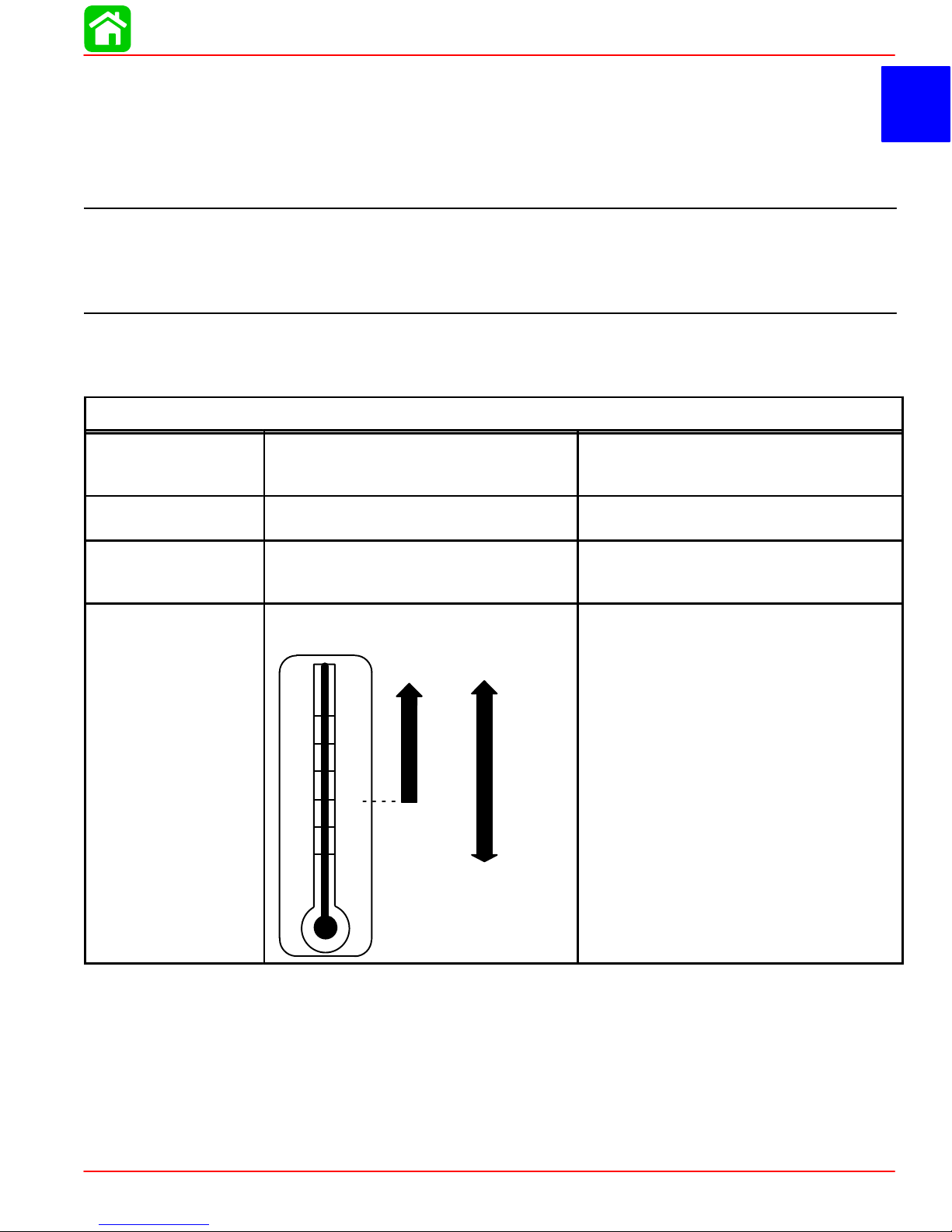
SPECIFICATIONS
IMPORTANT INFORMATION
Section 1A - Specifications
Table of Contents
Specifications 1A-1. . . . . . . . . . . . . . . . . . . . . . . . . . . . .
Gear Case Design Identification 1A-7. . . . . . . . . . . . .
Propeller Information Charts 1A-8. . . . . . . . . . . . . . . .
Mercury/Mariner 50 (4-Stroke)
2.00:1 Non Bigfoot 1A-8. . . . . . . . . . . . . . . . . . . . . .
Specifications
Models 40/45/50/50 (4-Stroke)
HORSEPOWER
(kW)
OUTBOARD
WEIGHT
FUEL
OIL
Model 50
Model 45
Model 40
Electric
40/45/50 ELPT
RECOMMENDED GASOLINE Automotive Unleaded
ENGINE OIL CAPACITY
ENGINE OIL
SAE
25W-40
F°
+100
+80
+60
+40
+20
0
C°
+38
+27
+16
+4
–7
–18
SAE
10W-30
1
A
Mercury/Mariner 50 (4-Stroke)
1.83:1 Non Bigfoot 1A-9. . . . . . . . . . . . . . . . . . . . . .
Mercury/Mariner 50 (4-Stroke)
2.3:1 Bigfoot 1A-10. . . . . . . . . . . . . . . . . . . . . . . . . .
50 hp (37.3 Kw) @ 6000 rpm
45 hp (33.5 Kw) @ 6000 rpm
40 hp (29.8 Kw) @ 6000 rpm
224 lb (102 kg)
with a Minimum Pump Posted
Octane Rating of 87
Either 3 Quarts or 3 Liters
SAE 10W-30 viscosity oil is recom-
mended for use in all temperatures.
SAE 25W-40 viscosity oil may be used at
temperatures above 40° F (4° C).
Use Quicksilver 4-Cycle Marine Oil with
the proper viscosity for the expected
temperature in your area (see range
thermometer on left). If not available, use
a premium quality 4-cycle engine oil, cer-
tified to meet or exceed anyone of the
following American Petroleum Institute
(API) service classification SH, SG, SF,
CF-4, CE, CD, CDll.
90-828631R3 MARCH 1999 Page 1A-1
Page 6

SPECIFICATIONS
IGNITION SYSTEM*
*Readings taken @ 68°F
(20°C).
CHARGING
SYSTEM
STARTING
SYSTEM
BATTERY
ENRICHMENT
CONTROL SYSTEM
FUEL SYSTEM
Type
Spark Plug Type (NGK)
Spark Plug Gap
Firing Order
Ignition Timing:
40/45 HP
Fully Retarded
Fully Advanced (2500-3000 rpm)
50 HP
Fully Retarded
Fully Advanced (2500-3000 rpm)
Charge Coil Resistance
Trigger Coil Resistance
Ignition Coil Resistance:
Primary
Secondary
cdi Engine Speed Limiter
cdi Overheat Speed Control
Engine Temperature Switch
Above 131° F (55° C)
Below 104° F (40° C)
Alternator Type
Alternator Output:
Electric Start
Lighting Coil Resistance (Grn - Grn)
Lighting Coil Output Peak Voltage
P/N 50-825095 Top Mounted
Electric Start:
Starter Type
Output
Ampere Draw Under:
(Load)
(No Load)
P/N 50-834749 Side Mounted
Starter Type
Output
Ampere Draw Under:
(Load)
(No Load)
Battery Rating
Minimum Requirement
For operation below 32° F (0° C)
Choke Solenoid
Electro-thermal ram projection
Fuel Pump Type
Fuel Pump:
Pressure
Diaphragm Stroke
Plunger Stroke
Fuel Tank Capacity
Capacitor Discharge Ignition
NGK DPR6EA-9
0.035 in. (1.0 mm)
1-3-4-2
5° B.T.D.C
25° B.T.D.C
5° B.T.D.C
35° B.T.D.C
272 - 408 Ω (BRN-BLU)
396 - 594 Ω (WHT/BLK-WHT/RED)
0.1 - 0.7 Ω
3.5 - 4.7 kΩ
6120 - 6280 rpm
1600 - 2400 rpm
No Continuity
Continuity
Three Phase
12 Volts - 10 Amps. (Regulated)
1.2 - 3.2 Ohms @ 68°F (20°C)
8.9 Volts @ 1500 rpm
Bendix
1.1 kW
106.0 Amps
21.1 Amps
Bendix
1.1 kW
95.0 Amps
20.0 Amps
465 Marine Cranking Amps (MCA)
or 350 Cold Cranking Amps (CCA).
1000 Marine Cranking Amps (MCA) or
775 Cold Cranking Amps (CCA)
3.2 - 4.8 Ω @ 68°F (20 °C)
0.3 in. (7 mm) after 5 min. of power
External (Plunger/Diaphragm)
3-6 psi (21-41 kPa)
0.14 - 0.20 in. (3.5 - 5.1 mm)
0.23 - 0.38 in. (5.85 - 9.65 mm)
Accessory
Page 1A-2 90-828631R3 MARCH 1999
Page 7
CARBURETOR
Idle rpm (Out Of Gear)
45 hp
40/50 hp
Idle rpm (In Forward Gear)
45 hp
40/50 hp
Wide Open Throttle rpm (WOT)
Range
Main Jet Size
40/45 hp
Carburetors 1 and 2
Carburetors 3 and 4
50 hp
Pilot Jet
Float Height
SPECIFICATIONS
950 ± 25 rpm
825 ± 25 rpm
850 ± 25 rpm
725 ± 25 rpm
5500–6000 rpm
#104
#103
#112
#42
0.39 ± 0.02 in. (10.0 ± 0.5 mm)
CYLINDER BLOCK
Type
Displacement
4 Stroke Cycle – Over Head Camshaft
57 cu. in. (935cc)
Number of Cylinders
STROKE Length 2.953 in. (75 mm)
Diameter
2.4803 in. (63.0 mm)
2.5003 in. (63.5 mm)
0.003 in. (0.08 mm)
CYLINDER BORE
Standard
Oversize-0.020 in. (0.050 mm)
Taper/Out of Round Maximum
Bore Type
PISTON
PISTON
Piston Type
O.D. at Skirt
Standard
Oversize-0.020 in. (0.50mm)
2.4783-2.4789 in. (62.950-62.965 mm)
2.4983-2.4989 in. (63.450-63.465 mm)
Piston to Cylinder Clearance 0.0014 - .0026 in. (0.035 - 0.065 mm)
Aluminum
CLEARANCE
Ring End Gap (Installed)
0.006 - 0.012 in. (0.15 - 0.30 mm)
0.012 - 0.020 in. (0.30 - 0.50 mm)
0.008 - 0.028 in. (0.20 - 0.70 mm)
RINGS
Top
Middle
Bottom (Oil Ring)
Side Clearance:
Top
Middle
0.002 - 0.003 in. (0.04 - 0.08 mm)
0.001 - 0.003 in. (0.03 - 0.08 mm)
4
Steel
COMPRESSION
RATIO
Compression Ratio
Cylinder Compression (cold engine
@ W.O.T.)
PISTON PIN Piston Pin Diameter 0.6285-0.6287 in. (15.965 - 15.970 mm)
CONNECTING
ROD
90-828631R3 MARCH 1999 Page 1A-3
Oil Clearance (Big End)
Small End Inside Diameter
9.8:1
2
170 -190 lb/in
(Peak)
0.0008 - 0.0020 in. (0.020 - 0.052 mm)
0.6293 - 0.6298 in. (15.985-15.998 mm)
Page 8
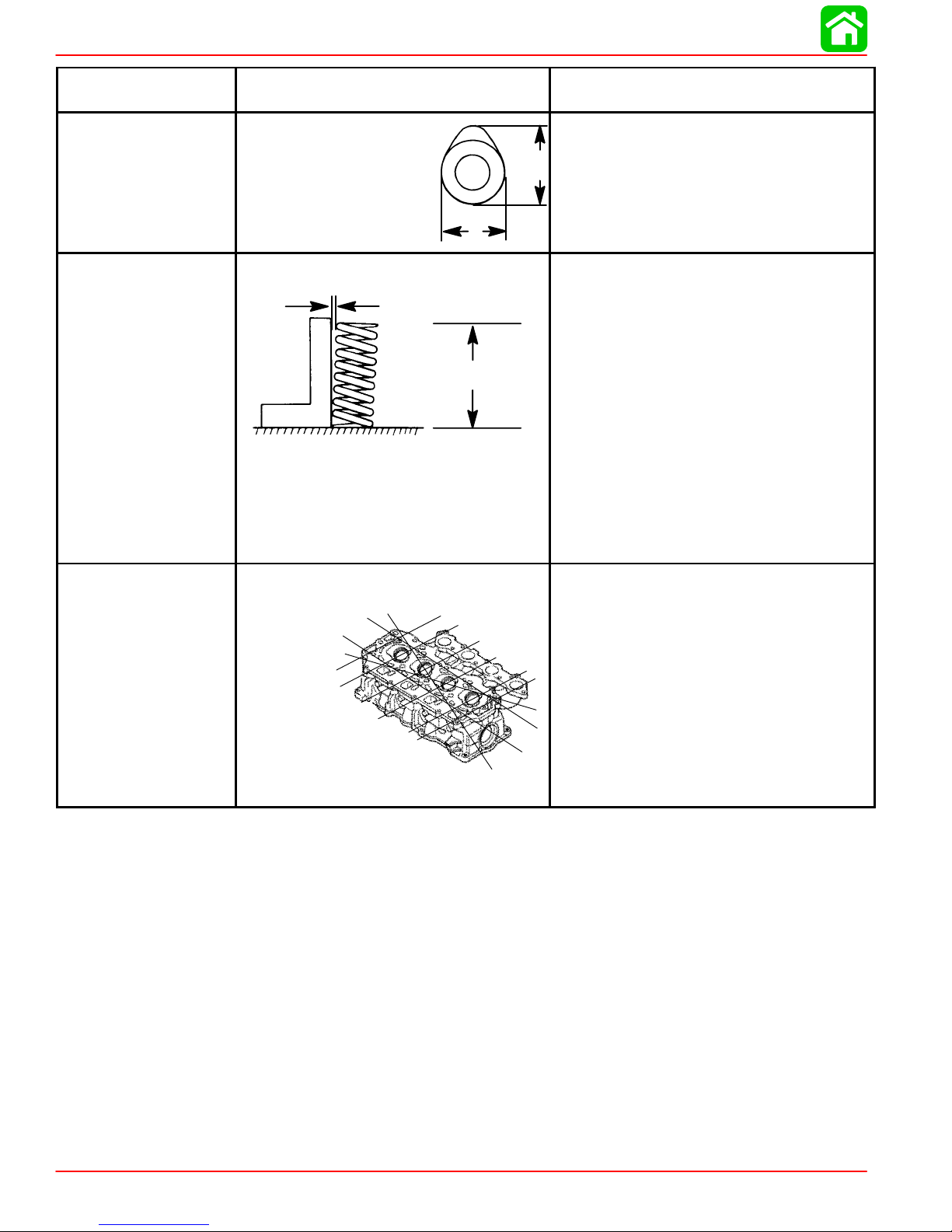
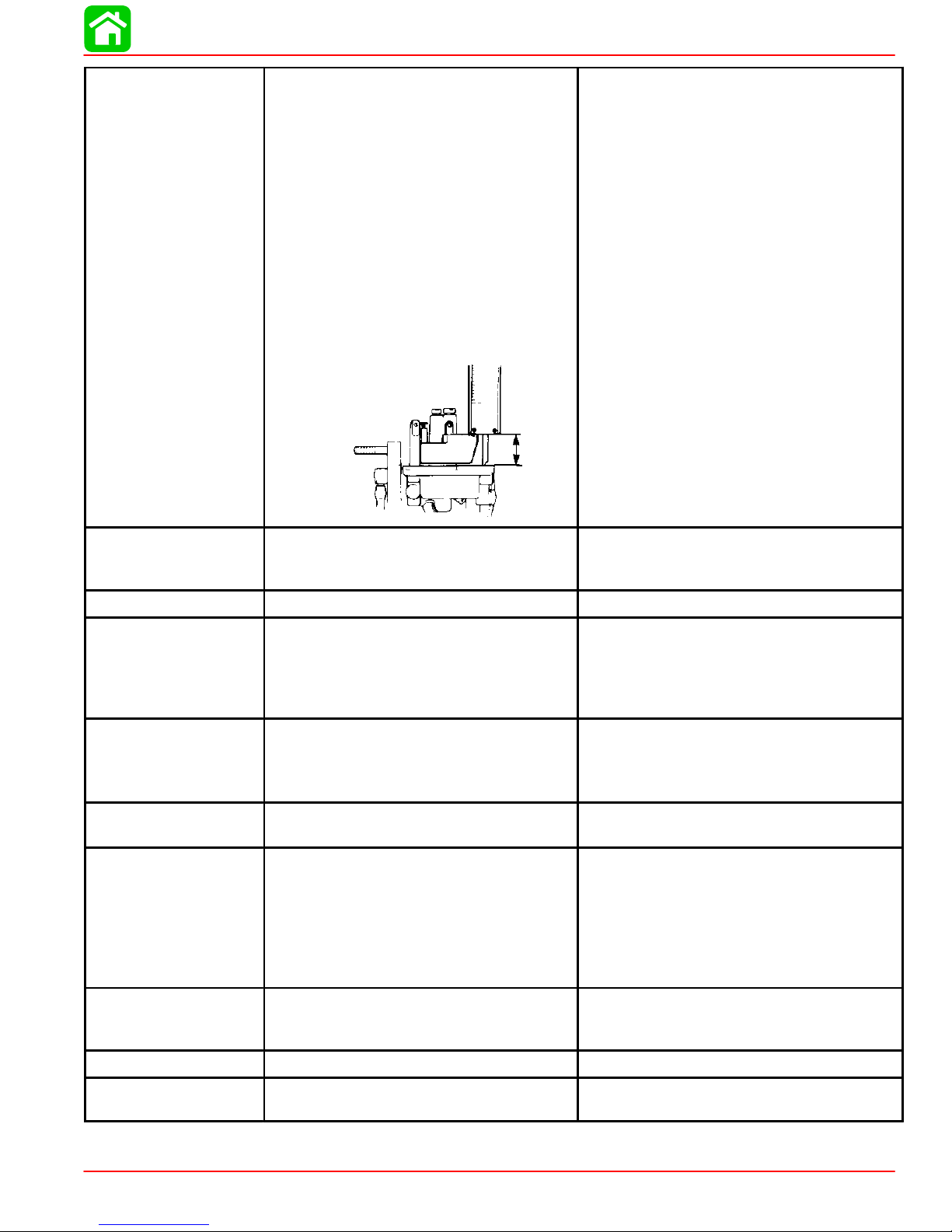
SPECIFICATIONS
CRANKSHAFT
CAMSHAFT
VALVE SPRING
Main Bearing Clearance
Crankshaft Run-out
Camshaft Dimensions
Intake “A”
Exhaust “A”
Intake “B”
Exhaust “B”
Run-out Limit
B
Free Length “a”
Tilt Limit “b”
b
a
Compressed Pressure (Installed)
Intake
Exhaust
Tilt Limit (Intake & Exhaust)
Dir. of Winding (Intake & Exhaust)
Warp Limit
0.0005 - 0.0017 in. (0.012 - 0.044 mm)
0.0012 in. (0.03 mm)
1.216 - 1.220 in. (30.89 - 30.99 mm)
1.213 - 1.217 in. (30.82 - 30.92 mm)
A
1.022 - 1.025 in. (25.95 - 26.05 mm)
1.022 - 1.025 in. (25.95 - 26.05 mm)
0.0039 in. (0.1 mm)
1.491-1.569 in. (37.85-39.85 mm)
Less than 0.060 in. (1.7 mm)
19.8 - 22.0 lb (9.0 - 10.0 kg)
19.8 - 22.0 lb (9.0 - 10.0 kg)
0.043 in. (1.1 mm)
Left Hand
0.004 in. (0.1 mm)
CYLINDER HEAD
* Lines indicate
straight edge
measurement
Page 1A-4 90-828631R3 MARCH 1999
Page 9
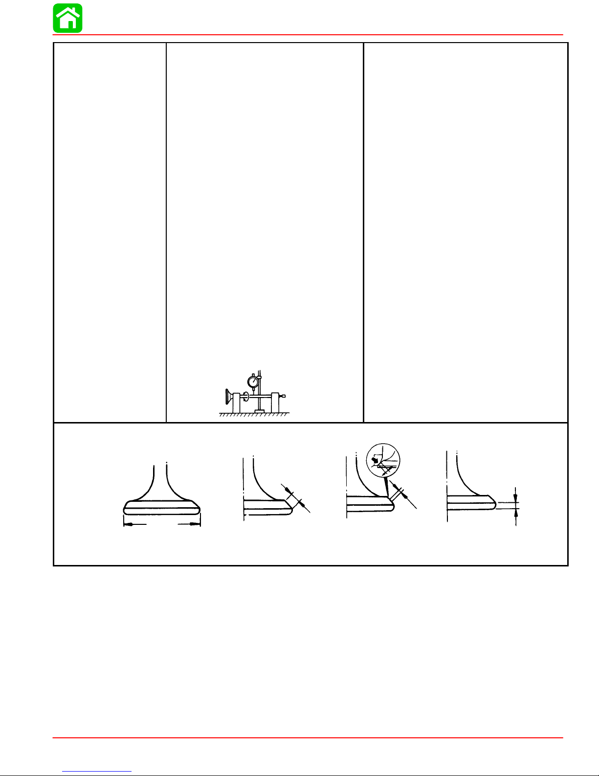
VALVES
Valve/Valve Seat/Valve Guides:
Valve Clearance (cold)
Intake
Exhaust
Valve Dimensions:
“A” Head Diameter
Intake
Exhaust
“B” Face Width
Intake
Exhaust
“C” Seat Width
Intake
Exhaust
“D” Margin Thickness
Intake
Exhaust
Stem Outside Diameter
Intake
Exhaust
Guide Inside Diameter
Intake
Exhaust
Stem To Guide Clearance
Intake
Exhaust
Stem Run-out Limit (max.)
SPECIFICATIONS
0.006 - 0.010 in. (0.15 - 0.25 mm)
0.010 - 0.014 in. (0.25 - 0.35 mm)
1.177 - 1.185 in. (29.9 - 30.1 mm)
1.020 - 1.028 in. (25.9 - 26.1 mm)
0.079 - 0.124 in. (2.00 - 3.14 mm)
0.079 - 0.124 in. (2.00 - 3.14 mm)
0.035 - 0.043 in. (0.9 - 1.1 mm)
0.035 - 0.043 in. (0.9 - 1.1 mm)
0.020 - 0.035 in. (0.5 - 0.9 mm)
0.020 - 0.035 in. (0.5 - 0.9 mm)
0.2156 - 0.2161 in. (5.475 - 5.490 mm)
0.2150 - 0.2156 in. (5.460 - 5.475 mm)
0.2165 - 0.2170 in. (5.500 - 5.512 mm)
0.2165 - 0.2170 in. (5.500 - 5.512 mm)
0.0004 - 0.0015 in. (0.010 - 0.037 mm)
0.0010 - 0.0020 in. (0.025 - 0.052 mm)
0.0006 in. (0.016 mm)
Valve Dimensions
“A”
Head Diameter Face Width
“B”
Seat Width
“C”
“D”
Margin Thickness
90-828631R3 MARCH 1999 Page 1A-5
Page 10
SPECIFICATIONS
THERMOSTAT
LUBRICATION
SYSTEM
MID-SECTION
1995/1996
GEAR HOUSING
(2.00:1)
Valve Opening Temperature
Full Open Temperature
Valve Lift
Pump Type
Engine Oil Pressure
Engine Oil Pan Capacity
Oil Pump:
Outer Rotor to Housing “a”
Inner Rotor to Outer Rotor “b”
Rotor to Housing “c”
a
b
c
Transom Height:
Long Shaft
Steering Pivot Range
Tilt Pin Positions
Full Tilt Up Angle
Allowable Transom Thickness
45/50 1995/1996 models
Gear Ratio
Gearcase Capacity
Lubricant Type
Forward Gear
Number of Teeth
Pinion Gear
Number of Teeth
Pinion Height
Forward Gear Backlash
Water Pressure
@ Idle
@ WOT
136° F - 143° F (58° C - 62° C)
158° F (70° C)
0.12 in. (3 mm)
Trochoid
30-40 psi at 3000 rpm (Warm Engine)
Either 3 Qts. or 3 Liters
0.001 - 0.006 in. (0.03 - 0.15 mm)
0.005 in. (0.12 mm)
0.001 - 0.003 in. (0.03 - 0.08 mm)
20 in. (51 cm)
90°
5 + Shallow Water
70°
2-3/8 in. (60.3 mm)
2.00:1
14.9 fl oz (440 mL)
Quicksilver Gear Lube-Premium Blend
26 Spiral/Bevel
13 Spiral/Bevel
0.025 in. (0.64 mm)
No Adjustment
2-4 psi (14-28 kPa) @ 750 rpm
12-17 psi (83-117 kPa) @ 6000 rpm
Page 1A-6 90-828631R3 MARCH 1999
Page 11
1997 AND NEWER
GEAR HOUSING
(1.83:1)
1998 AND NEWER
BIGFOOT GEAR
HOUSING
(2.3:1)
40/45/50 1997 and Newer models
Gear Ratio
Gearcase Capacity
Lubricant Type
Forward Gear
Number of Teeth
Pinion Gear
Number of Teeth
Pinion Height
Forward Gear Backlash
Water Pressure
@ Idle
@ WOT
Gear Ratio
Gearcase Capacity
Lubricant Type
Forward Gear
Number of Teeth
Pinion Gear
Number of Teeth
Pinion Height
Forward Gear Backlash
Water Pressure
@ 750 rpm (Idle)
@ 6000 rpm (WOT)
SPECIFICATIONS
1.83:1
14.9 fl oz (440 mL)
Quicksilver Gear Lube-Premium Blend
22 Spiral/Bevel
12 Spiral/Bevel
0.025 in. (0.64 mm)
No Adjustment
2-4 psi (14-28 kPa) @ 750 rpm
12-17 psi (83-117 kPa) @ 6000 rpm
2.3:1
22.5 fl oz (655 mL)
Quicksilver Gear Lube-Premium Blend
30 Spiral/Bevel
13 Spiral/Bevel
0.025 in. (0.64 mm)
0.012-0.019 in. (0.30-0.48 mm)
2-4 psi (14-28 kPa)
10-15 psi (69-103 kPa)
Gear Case Design Identification
a
“3 Jaw Reverse Clutch” “6 Jaw Reverse Clutch”
a-Design I - “3 Jaw Reverse Clutch” Gear Case Identifier
b-Design II - “6 Jaw Reverse Clutch” Gear Case Identifier
Identify gear case design to ensure correct components are being installed. Design I “3 Jaw Reverse Clutch” (a) gear case identified with straight machined edge for trim tab
screw mounting surface. Design II - “6 Jaw Reverse Clutch” (b) gear case identified with
angled machined edge for trim tab screw mounting surface.
b
90-828631R3 MARCH 1999 Page 1A-7
Page 12

SPECIFICATIONS
Propeller Information Charts
Mercury/Mariner 50 (4-Stroke) 2.00:1 Non Bigfoot
Wide Open Throttle rpm : 5500-6000
Recommended Transom Heights : 15”, 20”, 22.5”
Right Hand Rotation Standard
Gear Reduction : 2.00:1
Approx.
No. of
Diameter
10” 19” 3 Alum Up to 800 Up to 14’ 43-51 48-73146A40
10” 17” 3 Alum Up to 900 Up to 15’ 40-46 48-73144A40
10” 16” 3 Steel 800-1000 Up to 15’ 37-43 48-91818A5
10” 16” 3 Alum 800-1000 Up to 15’ 37-43 48-73142A40
10-1/8” 15” 3 Steel 900-1300 13-15’ 34-41 48-76232A5
10-1/8” 15” 3 Alum 900-1300 13-15’ 34-41 48-73140A40
10-3/8” 14” 3 Alum 1000-1500 14-16’ 32-37 48-816706A40
10-1/4” 14” 3 Steel 1000-1500 14-16’ 32-37 48-76230A5
10-1/4” 14” 3 Alum 1000-1500 14-16’ 32-37 48-73138A40
10-1/2” 13” 3 Alum 1100-1700 14-17’ 29-34 48-816704A40
10-3/8” 13” 3 Steel 1100-1700 14-17’ 29-34 48-76228A5
10-3/8” 13” 3 Alum 1100-1700 14-17’ 29-34 48-73136A40
10-3/4” 12” 3 Alum 1200-1900 15-17’ 25-31 48-816702A40
10-5/8” 12” 3 Steel 1200-1900 15-17’ 25-31 48-79792A5
10-5/8” 12” 3 Alum 1200-1900 15-17’ 25-31 48-73134A40
Pitch
Blades
Material
Gross Boat
Wgt. (lb)
Approx.
Boat
Length
Speed
Range
(mph)
Propeller
Part Number
10-7/8” 11” 3 Alum 1400-2100 16-18’ 22-27 48-85632A45
11-5/8” 11” 3 Steel 1400-2100 16’ + 22-27 48-823478A5
11-5/8” 10-1/2” 3 Alum 1500-2300 16’ + 20-25 48-827312A10
11-1/4” 10” 3 Alum 1700-2500 17’ + 18-23 48-73132A40
12-1/4” 9” 3 Steel 1900+ 18’ + 13-20 48-97868A10
12-1/4” 9” 3 Alum 1900+ 18’ + 13-20 48-87818A10
12-1/2” 8” 3 Alum 2100+ 18’ + 1-16 48-42738A10
12-1/2” 8” Cup 3 Alum pontoon 48-42738A12
Page 1A-8 90-828631R3 MARCH 1999
Page 13

Mercury/Mariner 50 (4-Stroke) 1.83:1 Non Bigfoot
Wide Open Throttle rpm : 5500-6000
Recommended Transom Heights : 15”, 20”, 22.5”
Right Hand Rotation Standard
Gear Reduction : 1.83:1
SPECIFICATIONS
Diameter
Pitch
No. of
Blades
Material
Approx.
Gross Boat
Wgt. (lb)
Approx.
Boat
Length
Speed
Range
(mph)
Propeller
Part Number
10” 19” 3 Alum Up to 800 Up to 14’ 49-58 48-73146A40
10” 17” 3 Alum Up to 900 Up to 15’ 43-50 48-73144A40
10” 16” 3 Steel 900-1300 Up to 15’ 39-46 48-91818A5
10” 16” 3 Alum 900-1300 Up to 15’ 39-46 48-73142A40
10-1/8” 15” 3 Steel 1000-1400 13-15’ 36-43 48-76232A5
10-1/8” 15” 3 Alum 1000-1400 13-15’ 36-43 48-73140A40
10-1/4” 14” 3 Steel 1100-1600 14-16’ 33-39 48-76230A5
10-1/4” 14” 3 Alum 1100-1600 14-16’ 33-39 48-73138A40
10-3/8” 13” 3 Steel 1300-1800 14-17’ 30-35 48-76228A5
10-3/8” 13” 3 Alum 1300-1800 14-17’ 30-35 48-73136A40
10-5/8” 12” 3 Steel 1400-2000 15-17’ 27-32 48-79792A5
10-5/8” 12” 3 Alum 1400-2000 15-17’ 27-32 48-73134A40
11-5/8” 11” 3 Steel 1700-2400 16-18’ 24-29 48-823478A5
10-7/8” 11” 3 Alum 1700-2400 16-18’ 24-29 48-85632A45
11-5/8” 10-1/2” 3 Alum 1900-2700 16’ + 21-25 48-827312A10
11-1/4” 10” 3 Alum 2100-3000 17’ + 19-24 48-73132A40
12-1/4” 9” 3 Steel 2500+ pontoon 17-21 48-97868A10
12-1/4” 9” 3 Alum 2500+ pontoon 17-21 48-87818A10
12-1/2” 8” 3 Alum 3000+ pontoon/
1-18 48-42738A10
houseboat
12-1/2” 8” Cup 3 Alum pontoon 48-42738A12
90-828631R3 MARCH 1999 Page 1A-9
Page 14

SPECIFICATIONS
Mercury/Mariner 50 (4-Stroke) 2.3:1 Bigfoot
Wide Open Throttle rpm : 5500-6000
Recommended Transom Heights : 20”, 25”
Right Hand Rotation Standard
Gear Reduction : 2.31:1
Approx.
No. of
Diameter
13” 18” 3 Steel Up to 1400 Up to 14’ 34-40 48-16988A45
13-1/4” 17” 3 Alum 1300-1600 Up to 14’ 32-38 48-77344A45
13-1/8” 16” 3 Steel 1400-1700 14-16’ 29-35 48-16986A45
13-3/4” 15” 3 Alum 1500-1900 14-16’ 27-32 48-77342A45
13-3/8” 14” 3 Steel 1700-2200 15-17’ 24-30 48-17314A45
14” 13” 3 Alum 1900-2400 16-18’ 22-27 48-77340A45
14” 12” 3 Steel 2500-3200 17’+ 18-24 48-17312A45
14” 11” 3 Alum 2800-4000 pontoon 17-21 48-77338A45
14” 10” 3 Alum 3000+ pontoon/work 14-19 48-854342A45
14” 9” 3 Alum 5000+ houseboat/
Pitch
Blades
Material
Gross Boat
Wgt. (lb)
Approx.
Boat
Length
work
Speed
Range
(mph)
1-15 48-854340A45
Propeller
Part Number
Mercury/Mariner 50 (4-Stroke) 2.3:1 Bigfoot
Special soft rubber hub propellers designed to reduce clutch rattle
Wide Open Throttle rpm : 5500-6000
Recommended Transom Heights : 20”, 25”
Right Hand Rotation Standard
Gear Reduction : 2.31:1
IMPORT ANT: These specially designed rubber hub propellers are rated for 50 horsepower MAXIMUM.
No. of
Diameter
14” 13” 3 Alum 1900-2400 16-18’ 22-27 48-77340A33
14” 11” 3 Alum 2800-4000 pontoon 17-21 48-77338A33
14” 10” 3 Alum 3000+ pontoon/work 14-19 48-854342A33
14” 9” 3 Alum 5000+ houseboat/
Page 1A-10 90-828631R3 MARCH 1999
Pitch
Blades
Material
Approx.
Gross Boat
Wgt. (lbs)
Approx.
Boat
Length
work
Speed
Range
(mph)
1-15 48-854340A33
Propeller
Part Number
Page 15
MAINTENANCE
IMPORTANT INFORMATION
Section 1B - Maintenance
Table of Contents
Special Tools 1B-1. . . . . . . . . . . . . . . . . . . . . . . . . . . . .
Quicksilver Lubricant/Sealant 1B-2. . . . . . . . . . . . . . .
Inspection And Maintenance Schedule 1B-4. . . . . . .
Before Each Use 1B-4. . . . . . . . . . . . . . . . . . . . . . .
After Each Use 1B-4. . . . . . . . . . . . . . . . . . . . . . . . .
Every 100 Hours of Use or Once yearly,
Whichever occurs first 1B-5. . . . . . . . . . . . . . . . . .
Every 300 Hours of Use or Three Years 1B-5. . .
Before Periods of Storage 1B-5. . . . . . . . . . . . . . .
Corrosion Control Anode 1B-6. . . . . . . . . . . . . . . . . . .
Spark Plug Inspection 1B-7. . . . . . . . . . . . . . . . . . . . . .
Battery Inspection 1B-7. . . . . . . . . . . . . . . . . . . . . . . . .
Fuse Replacement – Electric Start Models 1B-8. . . .
Timing Belt Inspection 1B-8. . . . . . . . . . . . . . . . . . . . .
Lubrication Points 1B-9. . . . . . . . . . . . . . . . . . . . . . . . .
Checking Power Trim Fluid 1B-10. . . . . . . . . . . . . . . .
1
B
Changing Engine Oil 1B-11. . . . . . . . . . . . . . . . . . . . . .
Oil Changing Procedure 1B-11. . . . . . . . . . . . . . . .
Changing Oil Filter 1B-12. . . . . . . . . . . . . . . . . . . . .
Oil Filling 1B-12. . . . . . . . . . . . . . . . . . . . . . . . . . . . .
Gear Case Lubrication 1B-13. . . . . . . . . . . . . . . . . . . .
3-1/4 In. (83mm) Diameter Gear Case 1B-13. . .
4-1/4 In. (108mm) Diameter Gear Case 1B-14. .
Storage Preparation 1B-16. . . . . . . . . . . . . . . . . . . . . .
Fuel System 1B-16. . . . . . . . . . . . . . . . . . . . . . . . . .
Protecting External Outboard
Components 1B-16. . . . . . . . . . . . . . . . . . . . . . . . . .
Protecting Internal Engine Components 1B-16. .
Gear Case 1B-16. . . . . . . . . . . . . . . . . . . . . . . . . . .
Positioning Outboard for Storage 1B-17. . . . . . . .
Battery Storage 1B-17. . . . . . . . . . . . . . . . . . . . . . .
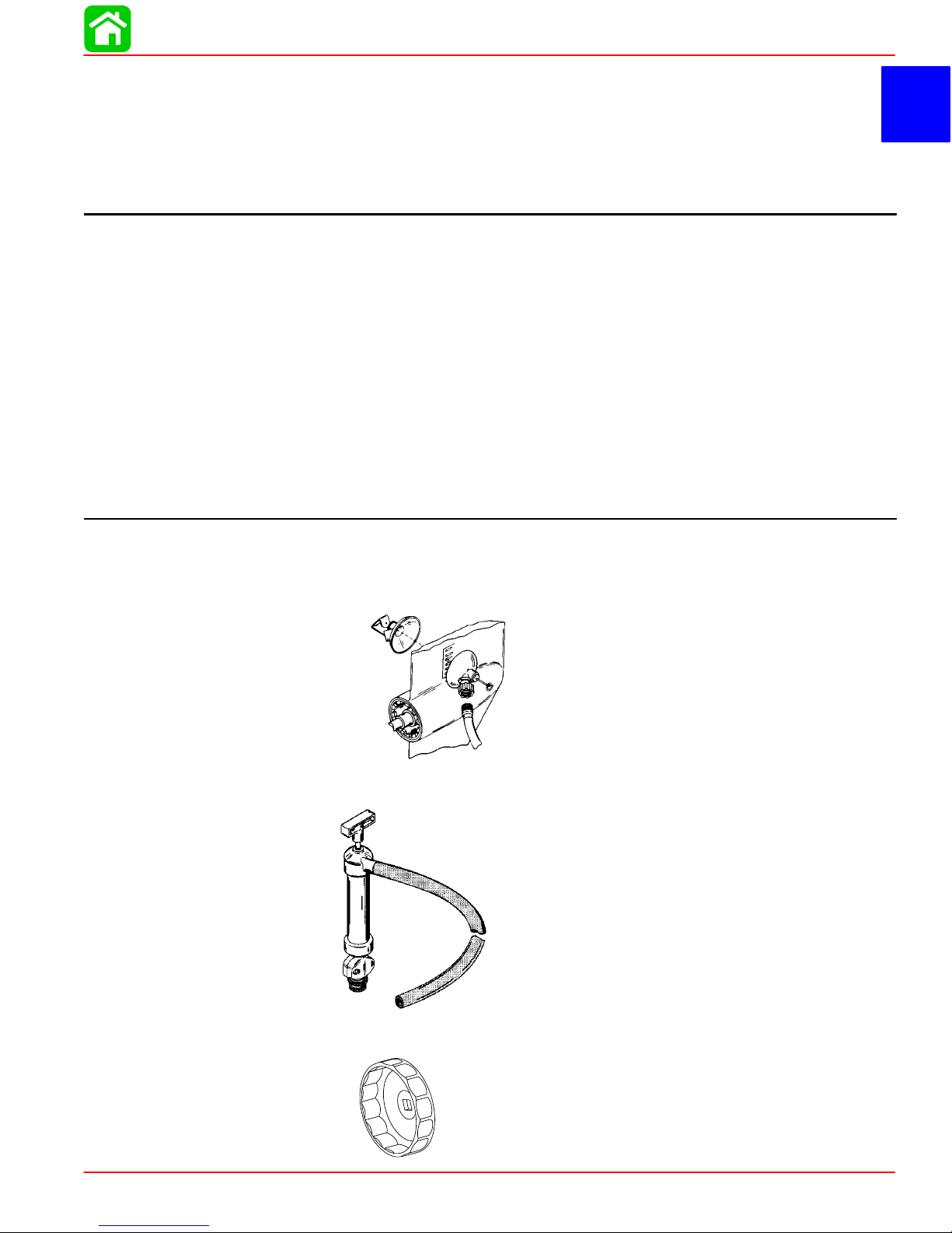
Special Tools
1. Flushing Attachment P/N 44357A2
2. Crankcase Oil Pump P/N 90265A2
3. Oil Filter Wrench P/N 91-802653
90-828631R3 MARCH 1999 Page 1B-1
Page 16
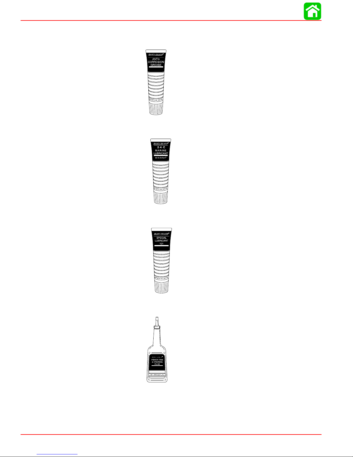
MAINTENANCE
Quicksilver Lubricant/Sealant
1. Quicksilver Anti-Corrosion Grease P/N 92-78376A6
2. 2-4-C Marine Lubricant with Teflon P/N 92-825407A12
3. Special Lubricant 101 P/N 92-13872A1
4. Quicksilver Power Trim and Steering Fluid P/N 92-190100A12
Page 1B-2 90-828631R3 MARCH 1999
Page 17
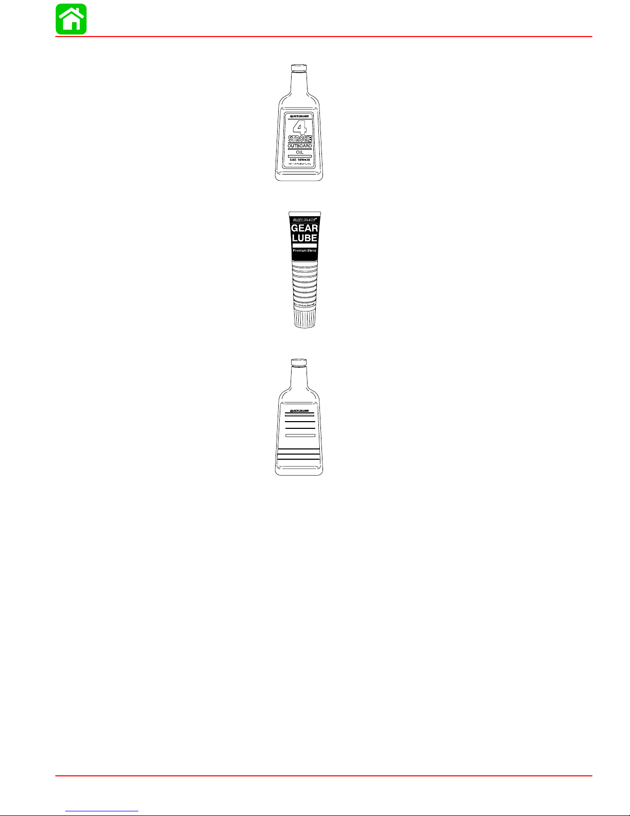
5. Quicksilver 4-Stroke Outboard Oil P/N 92-828000A12
6. Gear Lube-Premium Blend P/N 92-19007A24
MAINTENANCE
7. Quicksilver 4-Cycle Marine Engine Oil P/N 92-832111A1
4-CYCLE
MARINE
ENGINE OIL
Premium Blend
SAE 25W-40
NET 32 OZ (1 QT) 946 ml
90-828631R3 MARCH 1999 Page 1B-3
Page 18

MAINTENANCE
Inspection And Maintenance Schedule
To keep your outboard in the best operating condition, it is important that your outboard receive the periodic inspections and maintenance listed in the Inspection and Maintenance
Schedule. We urge you to keep it maintained properly to ensure the safety of you and your
passengers and retain its dependability.
WARNING
Neglected inspection and maintenance service of your outboard or attempting to
perform maintenance or repair on your outboard if you are not familiar with the correct service and safety procedures could cause personal injury, death, or product
failure.
Before Each Use
1. Check engine oil level.
2. Check that lanyard stop switch stops the engine.
3. Visually inspect the fuel system for deterioration or leaks.
4. Check outboard for tightness on transom.
5. Check steering system for binding or loose components.
6. Visually check steering link rod fasteners for proper tightness.
7. Check propeller blades for damage.
After Each Use
1. Flush out the outboard cooling system if operating in salt or polluted water.
2. Wash off all salt deposits and flush out the exhaust outlet of the propeller and gear case
with fresh water if operating in salt water.
Page 1B-4 90-828631R3 MARCH 1999
Page 19

Every 100 Hours of Use or Once yearly, Whichever occurs first
1. Lubricate all lubrication points. Lubricate more frequently when used in salt water.
2. Change engine oil and replace the oil filter. The oil should be changed more often when
the engine is operated under adverse conditions such as extended trolling.
3. Inspect thermostat visually for corrosion, broken spring, and to determine that the valve
is completely closed at room temperature. If questionable, inspect thermostat as outlined in Section 4B “Thermostat”.
4. Inspect and clean spark plugs.
5. Check engine fuel filter for contaminants.
6. Adjust carburetor(s) (if required).
7. Check engine timing setup.
8. Check corrosion control anodes. Check more frequently when used in salt water.
9. Drain and replace gear case lubricant.
10. Lubricate splines on the drive shaft.
11. Check and adjust valve clearance, if necessary.
12. Check power trim fluid.
MAINTENANCE
13. Inspect battery.
14. Check control cable adjustments.
15. Inspect timing belt.
16. Remove engine deposits with Quicksilver Power Tune Engine Cleaner.
17. Check tightness of bolts, nuts, and other fasteners.
Every 300 Hours of Use or Three Years
1. Replace water pump impeller (more often if overheating occurs or reduced water pres-
sure is noted).
Before Periods of Storage
1. Refer to Storage procedure (this section).
90-828631R3 MARCH 1999 Page 1B-5
Page 20
MAINTENANCE
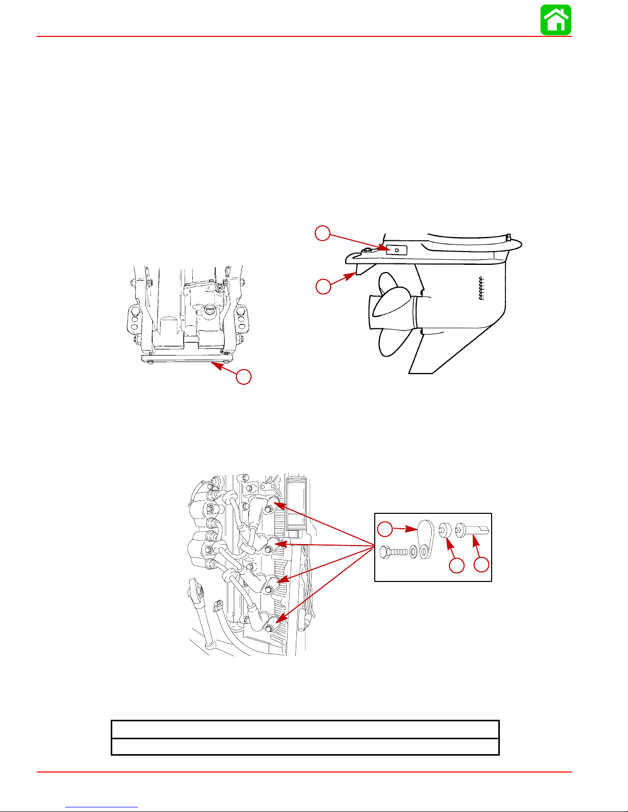
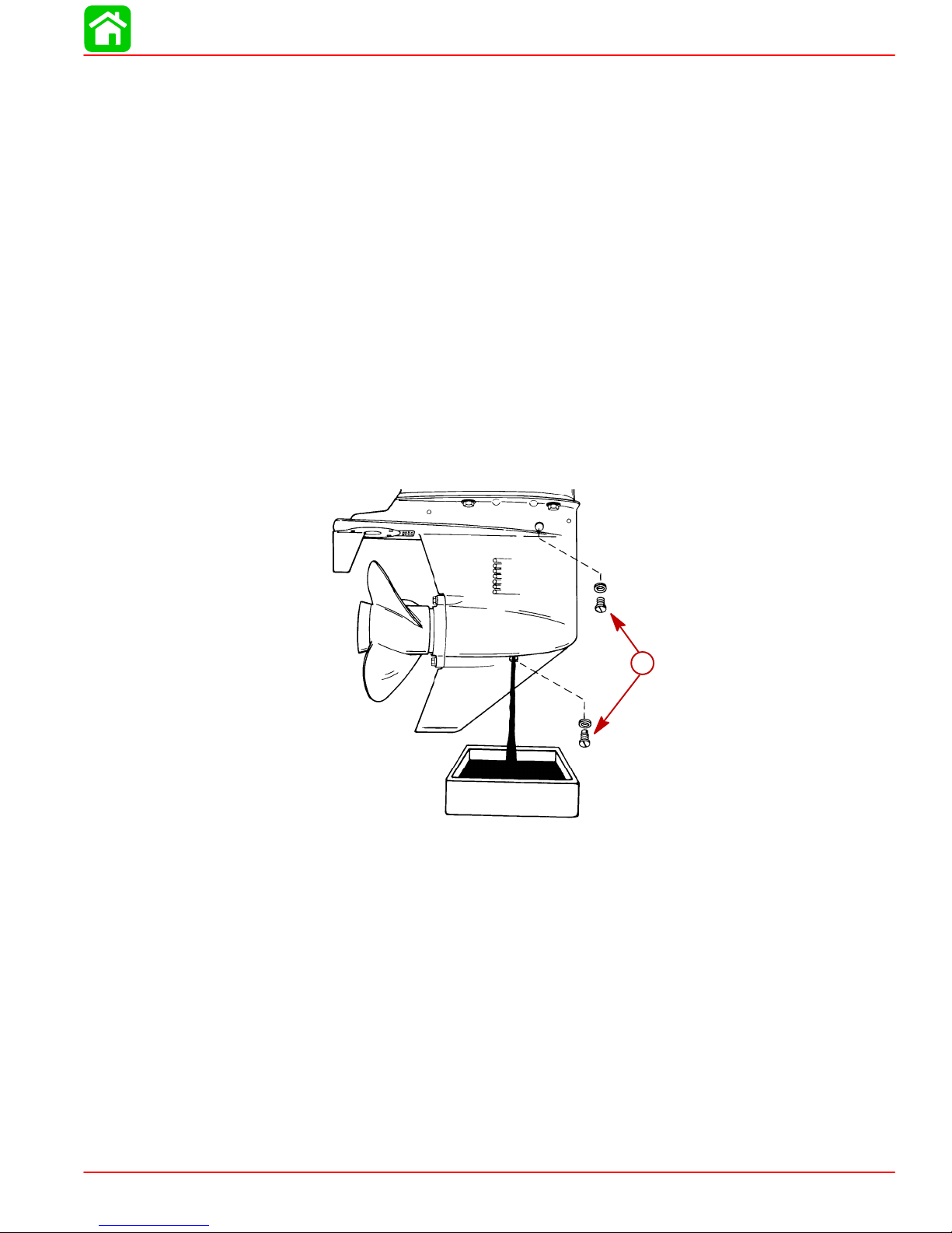
Corrosion Control Anode
Your outboard has control anodes at different locations. An anode helps protect the outboard against galvanic corrosion by sacrificing its metal to be slowly eroded instead of the
outboard metals.
Each anode requires periodic inspection especially in salt water which will accelerate the
erosion. To maintain this corrosion protection, always replace the anode before it is completely eroded. Never paint or apply a protective coating on the anode as this will reduce
effectiveness of the anode.
1. An anode is installed on the bottom of the transom bracket assembly. Trim tab is also
an anode on the 3-1/4 in. (83 mm) diameter gear case. The 4-1/4 in. (108 mm) diameter
gear case has three anodes. One of the anodes is the trim tab and two anodes are located on the side.
c
b
a
a-Bottom Anode
b-Trim Tab
c-Side Anodes
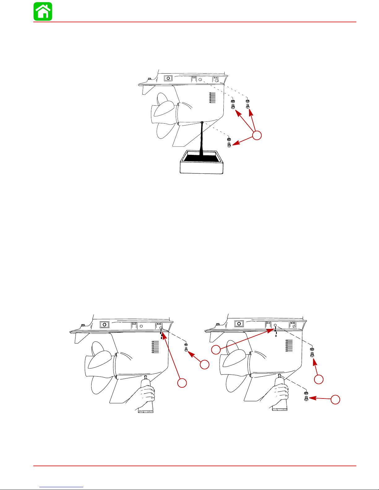
2. Four anodes are installed in the engine block. Remove anodes at locations shown.
Install each anode with rubber seal and cover. Torque bolts to specified torque.
c
a
b
a-Anodes-Engine Block
b-Rubber Seal
c-Cover
Page 1B-6 90-828631R3 MARCH 1999
Bolt Torque
70 lb-in. (8 Nm)
Page 21
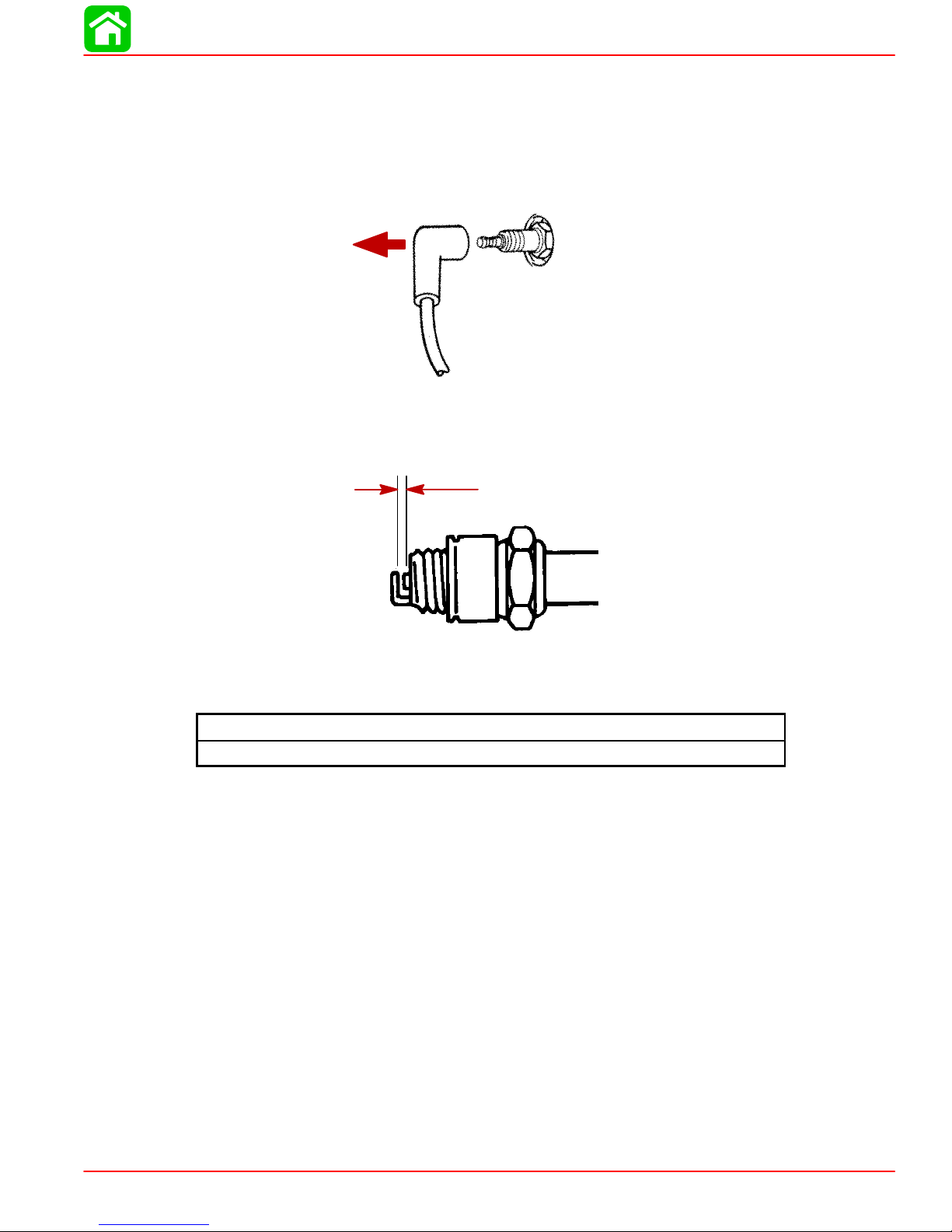
Spark Plug Inspection
Inspect spark plugs at the recommended intervals.
1. Remove the spark plug leads by twisting the rubber boots slightly and pull off.
2. Remove the spark plugs to inspect and clean. Replace spark plug if electrode is worn
or the insulator is rough, cracked, broken, blistered or fouled.
3. Set the spark plug gap. See Specification Chart.
MAINTENANCE
4. Before reinstalling spark plugs, clean away dirt on the spark plug seats. Install plugs fin-
ger tight, and tighten 1/4 turn or torque to specified torque.
Battery Inspection
The battery should be inspected at periodic intervals to ensure proper engine starting capability .
IMPORT ANT: Read the safety and maintenance instructions which accompany your
battery .
1. Turn off the engine before servicing the battery.
2. Add water as necessary to keep the battery full.
3. Make sure the battery is secure against movement.
4. Battery cable terminals should be clean, tight, and correctly installed. Positive to positive
and negative to negative.
5. Make sure the battery is equipped with a nonconductive shield to prevent accidental
shorting of battery terminals.
Spark Plug Torque
20 lb-in. (27 Nm)
90-828631R3 MARCH 1999 Page 1B-7
Page 22
MAINTENANCE
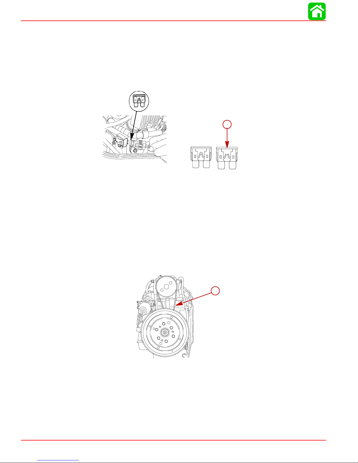
Fuse Replacement – Electric Start Models
The electric starting circuit is protected from overload by an SFE 20 AMP fuse. If the fuse
is blown, the electric starter motor will not operate. Try to locate and correct the cause of
the overload. If the cause is not found, the fuse may blow again. Replace the fuse with a
fuse of the same rating.
1. Open the fuse holder and look at the silver colored band inside the fuse. If band is broken
replace the fuse. Replace fuse with a new fuse with the same rating.
a
a-Blown Fuse
Timing Belt Inspection
1. Inspect the timing belt and replace if any of the following conditions are found.
a. Cracks in the back of the belt or in the base of the belt teeth.
b. Excessive wear at the roots of the cogs.
c. Rubber portion swollen by oil.
d. Belt surfaces roughened.
e. Signs of wear on edges or outer surfaces of belt.
a-Timing Belt
a
Page 1B-8 90-828631R3 MARCH 1999
Page 23
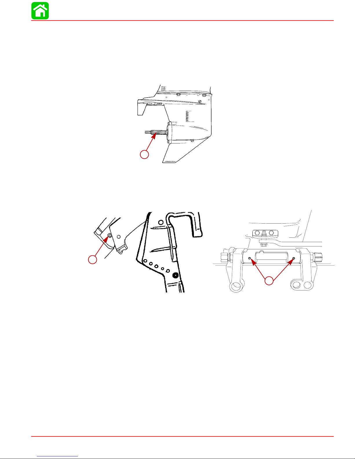
Lubrication Points
Lubricate Point 1 with Quicksilver Anti-Corrosion Grease or 2-4-C Marine Lubricant
with Teflon
1. Propeller Shaft – Refer to Propeller Replacement for removal and installation of the pro-
peller. Coat the entire propeller shaft with lubricant to prevent the propeller hub from corroding and seizing to the shaft.
Lubricate Points 2 thru 4 with Quicksilver 2-4-C Marine Lubricant with T eflon or Special Lubricant 101.
MAINTENANCE
1
2. Swivel Bracket – Lubricate through fitting.
3. Tilt Support Lever – Lubricate through fitting.
2
3
90-828631R3 MARCH 1999 Page 1B-9
Page 24
MAINTENANCE
Lubricate Point 4 with light weight oil.
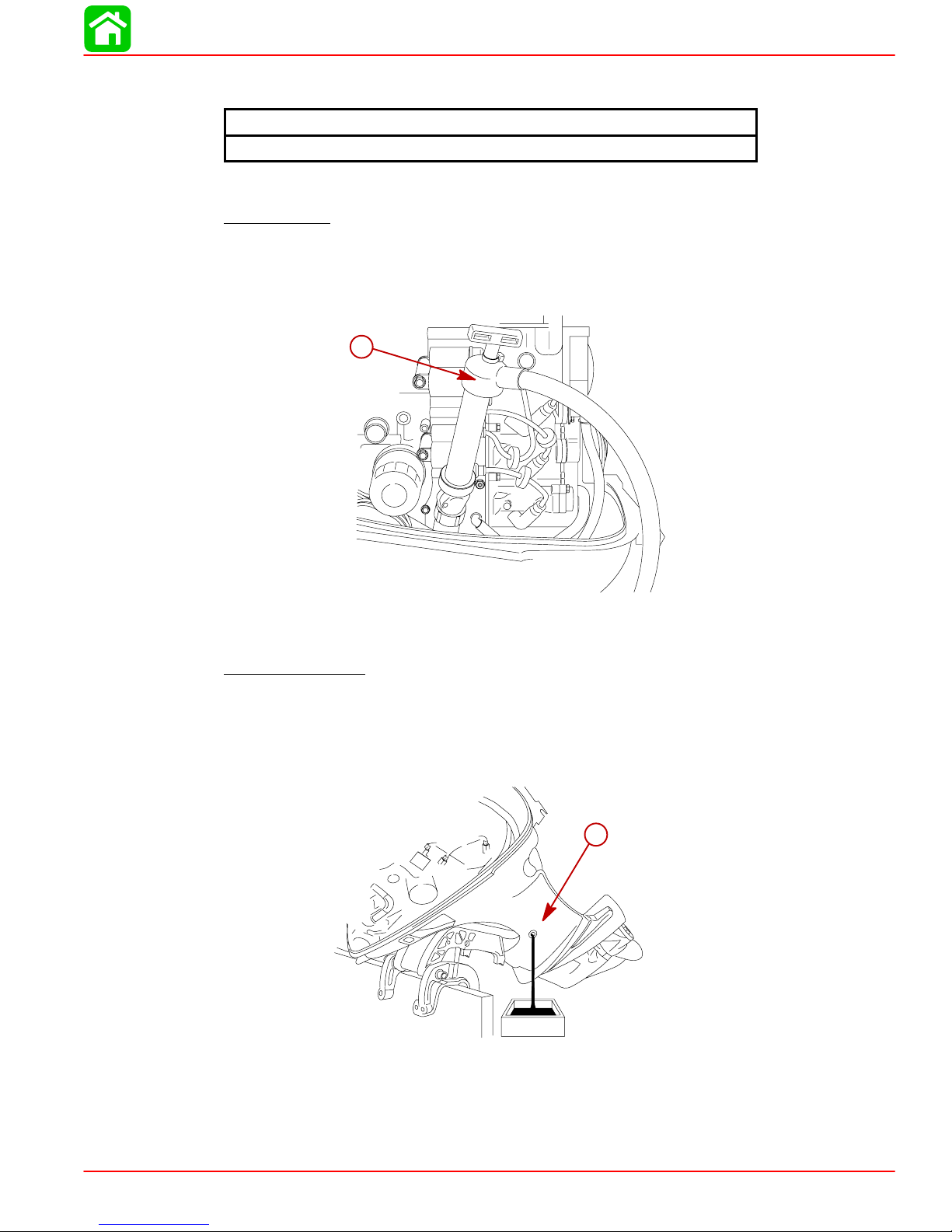
4. Steering Cable Grease Fitting – Rotate steering wheel to fully retract the steering cable
end into the outboard tilt tube. Lubricate through fitting. Lubricate steering link rod pivot
points with light weight oil.
b
a
4
a-Steering Cable End
b-Fitting
WARNING
The end of the steering cable must be fully retracted into the outboard tilt tube before adding lubricant. Adding lubricant to steering cable when fully extended could
cause steering cable to become hydraulically locked. An hydraulically locked steering cable will cause loss of steering control, possibly resulting in serious injury or
death.
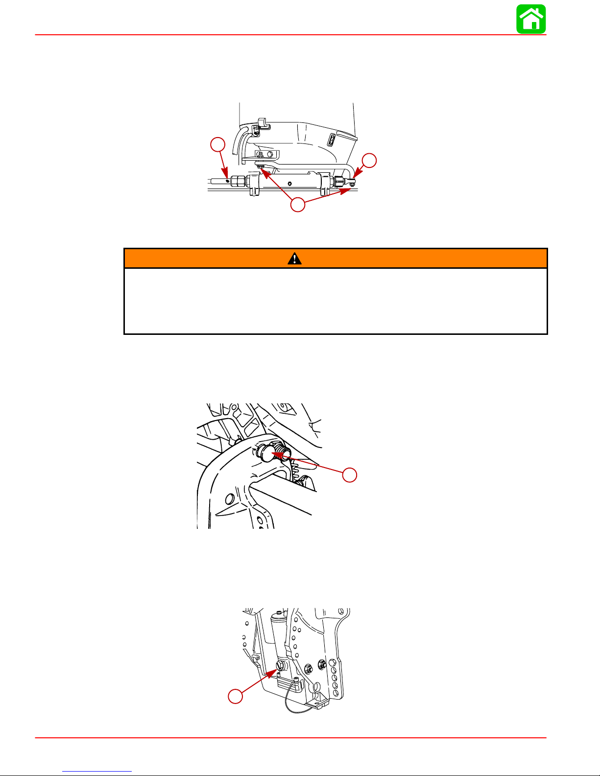
Checking Power Trim Fluid
1. Tilt outboard to the full up position and engage the tilt support lock.
a-Tilt Support Lock
2. Remove fill cap and check fluid level. The fluid level should be even with the bottom of
the fill hole. Add Quicksilver Power Trim & Steering Fluid. If not available, use automotive (ATF) automatic transmission fluid.
a
a-Fill Cap
Page 1B-10 90-828631R3 MARCH 1999
a
Page 25
Changing Engine Oil
Oil Changing Procedure
Pump Method
1. Place the outboard in an vertical upright position.
2. Remove dipstick and thread a Quicksilver Crankcase Oil Pump onto the dipstick tube.
Pump out the engine oil into an appropriate container.
MAINTENANCE
Engine Oil Capacity
3 U.S. Quarts (3.0 Liters)
a
a-Crankcase Oil Pump
Drain Plug Method
1. Tilt the outboard up to the trailer position.
2. Turn the steering on the outboard so that the drain hole is facing downward. Remove
drain plug and drain engine oil into an appropriate container. Lubricate the seal on the
drain plug with oil and reinstall.
a
a-Drain Hole
90-828631R3 MARCH 1999 Page 1B-1 1
Page 26
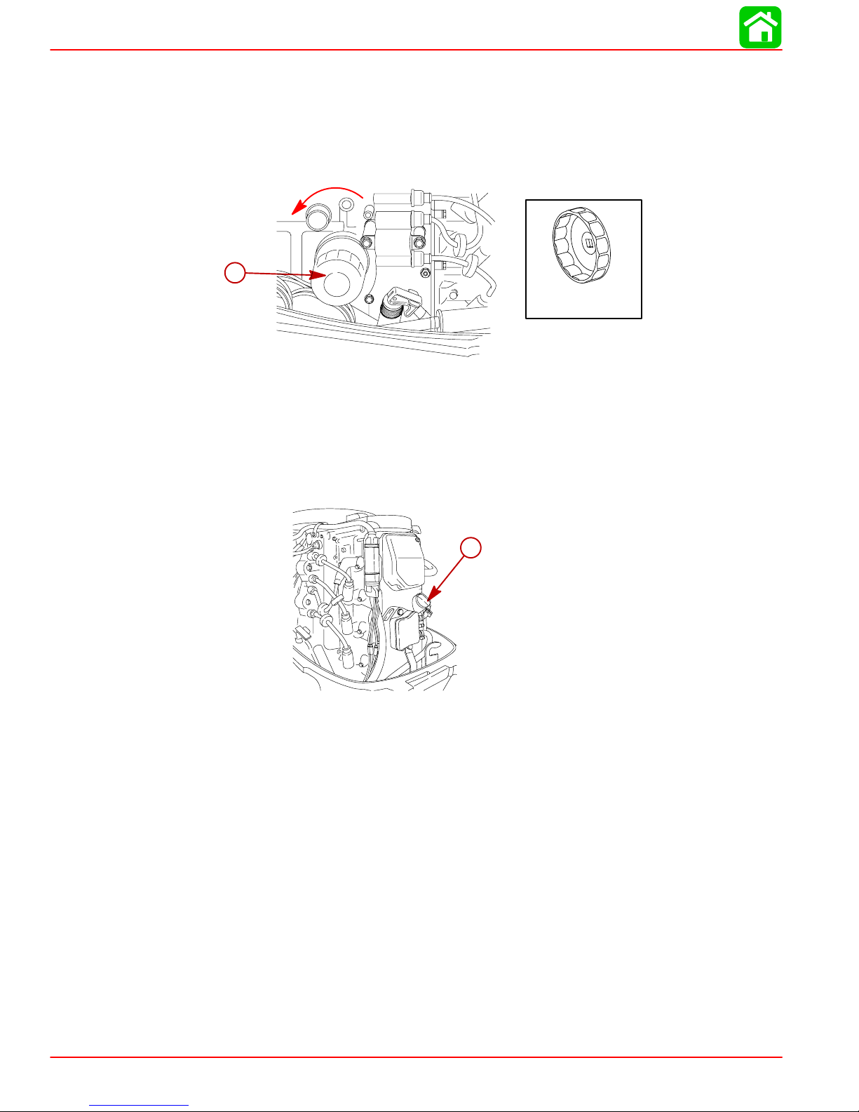
MAINTENANCE
Changing Oil Filter
1. Place a rag or towel below the oil filter to absorb any spilled oil.
2. Unscrew old filter by turning the filter counterclockwise.
3. Clean the mounting base. Apply film of clean oil to filter gasket. Do not use grease.
Screw new filter on until gasket contacts base, then tighten 3/4 to 1 turn.
a-Oil Filter
Oil Filling
1. Remove the oil fill cap and add oil to the proper operating level.
a
91-802653
2. Idle engine for five minutes and check for leaks. Stop engine and check oil level on dipstick. Add oil if necessary.
a
a-Oil Fill Cap
Page 1B-12 90-828631R3 MARCH 1999
Page 27
Gear Case Lubrication
When adding or changing gear case lubricant, visually check for the presence of water in
the lubricant. If water is present, it may have settled to the bottom and will drain out prior
to the lubricant, or it may be mixed with the lubricant, giving it a milky colored appearance.
If water is noticed, have the gear case checked by your dealer.Water in the lubricant may
result in premature bearing failure or, in freezing temperatures, will turn to ice and damage
the gear case.
Whenever you remove the fill/drain plug, examine the magnetic end for metal particles. A
small amount of metal filings or fine metal particles indicates normal gear wear. An excessive amount of metal filings or larger particles (chips) may indicate abnormal gear wear and
should be checked by an authorized dealer.
3-1/4 In. (83mm) Diameter Gear Case
DRAINING GEAR CASE
1. Place outboard in a vertical operating position.
2. Place a drain pan below outboard.
3. Remove vent plug and fill/drain plug and drain lubricant.
MAINTENANCE
a-Vent Plug and Fill/Drain Plug
GEAR CASE LUBRICANT CAPACITY
Gear case lubricant capacity is approximately 14.9 fl oz (440 ml).
a
90-828631R3 MARCH 1999 Page 1B-13
Page 28
MAINTENANCE
CHECKING GEAR CASE LUBRICANT LEVEL AND REFILLING GEAR CASE
1. Place outboard in a vertical operating position.
2. Remove vent plug.
3. Place lubricant tube into the fill hole and add lubricant until it appears at the vent hole.
IMPORTANT: Replace sealing washers if damaged.
4. Stop adding lubricant. Install the vent plug and sealing washer before removing the lubricant tube.
5. Remove lubricant tube and reinstall cleaned fill/drain plug and sealing washer.
c
a
b
a-Vent Plug/Sealing Washer
b-Lubricant Tube
c-Vent Hole
d-Fill/Drain Plug and Sealing Washer
4-1/4 In. (108mm) Diameter Gear Case
When adding or changing gear case lubricant, visually check for the presence of water in
the lubricant. If water is present, it may have settled to the bottom and will drain out prior
to the lubricant, or it may be mixed with the lubricant, giving it a milky colored appearance.
If water is noticed, have the gear case checked by your dealer. Water in the lubricant may
result in premature bearing failure or, in freezing temperatures, will turn to ice and damage
the gear case.
Whenever you remove the fill/drain plug, examine the magnetic end for metal particles. A
small amount of metal filings or fine metal particles indicates normal gear wear. An excessive amount of metal filings or larger particles (chips) may indicate abnormal gear wear and
should be checked by an authorized dealer.
d
Page 1B-14 90-828631R3 MARCH 1999
Page 29
DRAINING GEAR CASE
1. Place outboard in a vertical operating position.
2. Place a drain pan below outboard.
3. Remove vent plugs and fill/drain plug and drain lubricant.
a-Vent Plugs and Fill/Drain Plug
MAINTENANCE
a
GEAR CASE LUBRICANT CAPACITY
Gear case lubricant capacity is approximately 22.5 fl oz (655 ml).
CHECKING LUBRICANT LEVEL AND FILLING GEAR CASE
1. Place outboard in a vertical operating position.
2. Remove the front vent plug and rear vent plug.
3. Place lubricant tube into the fill hole and add lubricant until it appears at the front vent
hole. At this time install the front vent plug and sealing washer.
4. Continue adding lubricant until it appears at the rear vent hole.
5. Stop adding lubricant. Install the rear vent plug and sealing washer before removing
lubricant tube.
6. Remove lubricant tube and reinstall cleaned fill/drain plug and sealing washer.
d
a
a-Front Vent Plug
b-Rear Vent Plug
c-Front Vent Hole
d-Rear Vent Hole
e-Fill/Drain Plug and Sealing Washer
90-828631R3 MARCH 1999 Page 1B-15
c
b
e
Page 30

MAINTENANCE
Storage Preparation
The major consideration in preparing your outboard for storage is to protect it from rust, corrosion, and damage caused by freezing of trapped water.
The following storage procedures should be followed to prepare your outboard for out-ofseason storage or prolonged storage (two months or longer).
Never start or run your outboard (even momentarily) without water circulating
through the cooling water intake in the gear case to prevent damage to the water
pump (running dry) or overheating of the engine.
Fuel System
IMPORT ANT: Gasoline containing alcohol (ethanol or methanol) can cause a formation of acid during storage and can damage the fuel system. If the gasoline being use
contains alcohol, it is advisable to drain as much of the remaining gasoline as possible from the fuel tank, remote fuel line, and engine fuel system.
Fill the fuel system (tank, hoses, fuel pump, and carburetor) with treated (stabilized) fuel to
help prevent formation of varnish and gum. Proceed with following instructions.
1. Portable Fuel T ank – Pour the required amount of Quicksilver Gasoline Stabilizer (follow
instructions on container) into fuel tank. Tip fuel tank back and forth to mix stabilizer with
the fuel.
CAUTION
2. Permanently Installed Fuel Tank – Pour the required amount of Quicksilver Gasoline
Stabilizer (follow instructions on container) into a separate container and mix with
approximately one quart (one liter) of gasoline. Pour this mixture into fuel tank.
3. Place the outboard in water or connect flushing attachment for circulating cooling water.
Run the engine for ten minutes to allow treated fuel to reach the carburetor.
Protecting External Outboard Components
1. Lubricate all outboard components listed in the Inspection and Maintenance Schedule.
2. Touch up any paint nicks.
3. Spray Quicksilver Corrosion Guard on external metal surfaces (except corrosion control
anodes).
Protecting Internal Engine Components
1. Remove the spark plugs and inject a small amount of engine oil inside of each cylinder.
2. Rotate the flywheel manually several times to distribute the oil in the cylinders. Reinstall
spark plugs.
3. Change the engine oil.
Gear Case
1. Drain and refill the gear case lubricant (refer to maintenance procedure).
Page 1B-16 90-828631R3 MARCH 1999
Page 31

Positioning Outboard for Storage
Store outboard in an upright (vertical) position to allow water to drain out of outboard.
If outboard is stored tilted up in freezing temperature, trapped cooling water or rain
water that may have entered the propeller exhaust outlet in the gear case could
freeze and cause damage to the outboard.
Battery Storage
1. Follow the battery manufacturer’s instructions for storage and recharging.
2. Remove the battery from the boat and check water level. Recharge if necessary.
3. Store the battery in a cool, dry place.
4. Periodically check the water level and recharge the battery during storage.
MAINTENANCE
CAUTION
90-828631R3 MARCH 1999 Page 1B-17
Page 32

GENERAL INFORMATION
IMPORTANT INFORMATION
Section 1C - General Information
Table of Contents
Serial Number Location 1C-1. . . . . . . . . . . . . . . . . . . .
Conditions Affecting Performance 1C-2. . . . . . . . . . .
Weather 1C-2. . . . . . . . . . . . . . . . . . . . . . . . . . . . . . .
Boat 1C-3. . . . . . . . . . . . . . . . . . . . . . . . . . . . . . . . . .
Engine 1C-4. . . . . . . . . . . . . . . . . . . . . . . . . . . . . . . .
Following Complete Submersion 1C-5. . . . . . . . . . . .
Submerged While Running
(Special Instructions) 1C-5. . . . . . . . . . . . . . . . . . .
Salt Water Submersion
(Special Instructions) 1C-5. . . . . . . . . . . . . . . . . . .
Fresh Water Submersion
(Special Instructions) 1C-5. . . . . . . . . . . . . . . . . . .
Propeller Selection 1C-6. . . . . . . . . . . . . . . . . . . . . . . .
Propeller Removal/Installation 1C-7. . . . . . . . . . . . . .
Standard Models 1C-7. . . . . . . . . . . . . . . . . . . . . . .
Serial Number Location
1
C
Power Trim System 1C-9. . . . . . . . . . . . . . . . . . . . . . . .
General Information 1C-9. . . . . . . . . . . . . . . . . . . .
Power Trim Operation 1C-9. . . . . . . . . . . . . . . . . . .
Trim “In” Angle Adjustment 1C-10. . . . . . . . . . . . .
Trim Tab Adjustment 1C-12. . . . . . . . . . . . . . . . . . . . . .
Compression Check 1C-12. . . . . . . . . . . . . . . . . . . . . .
Cylinder Leakage Testing 1C-13. . . . . . . . . . . . . . . . . .
Analysis 1C-13. . . . . . . . . . . . . . . . . . . . . . . . . . . . . .
Painting Procedures 1C-14. . . . . . . . . . . . . . . . . . . . . .
Cleaning & Painting Aluminum
Propellers & Gear Housings 1C-14. . . . . . . . . . . .
Decal Application 1C-15. . . . . . . . . . . . . . . . . . . . . . . . .
Decal Removal 1C-15. . . . . . . . . . . . . . . . . . . . . . . .
Instructions for “Wet” Application 1C-15. . . . . . . .
The Outboard serial number is located on the lower starboard side of the engine block. A
serial number is also located on the starboard side of the swivel bracket.
a
OGXXXXXX
19XX
XXXX
b
c
e
XX
a - Serial Number
b - Model Year
c - Model Description
d - Year Manufactured
e - Certified Europe Insignia
d
90-828631R3 MARCH 1999 Page 1C-1
Page 33

GENERAL INFORMATION
Conditions Affecting Performance
Weather
Rated hp
Horsepower Loss
Due to Atmosphere
Summer hp
Conditions
Secondary Loss Due to
Propeller Becoming To
Large for Summer
Horsepower
RPM Drop Due
to Weather
ENGINE RPM
Rated RPM
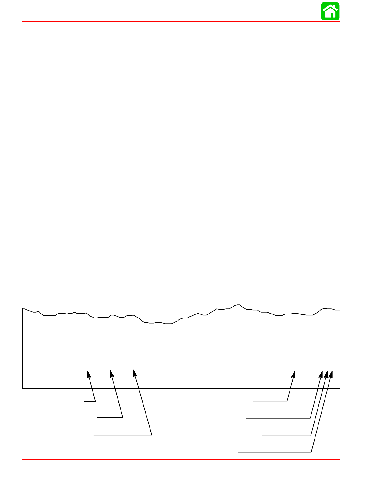
It is a known fact that weather conditions exert a profound effect on power output of internal
combustion engines. Therefore, established horsepower ratings refer to the power that the
engine will produce at its rated rpm under a specific combination of weather conditions.
Corporations internationally have settled on adoption of I.S.O. (International Standards Organization) engine test standards, as set forth in I.S.O. 3046 standardizing the computation
of horsepower from data obtained on the dynamometer, correcting all values to the power
that the engine will produce at sea level, at 30% relative humidity at 77° F (25°C) temperature and a barometric pressure of 29.61 inches of mercury.
Summer Conditions of high temperature, low barometric pressure and high humidity all
combine to reduce the engine power. This, in turn, is reflected in decreased boat speeds--as
much as 2 or 3 miles-per-hour (3 or 5 Km per-hour) in some cases. (Refer to previous chart.)
Nothing will regain this speed for the boater, but the coming of cool, dry weather.
In pointing out the practical consequences of weather effects, an engine--running on a hot,
humid summer day--may encounter a loss of as much as 14% of the horsepower it would
produce on a dry , brisk spring or fall day . The horsepower , that any internal combustion engine produces, depends upon the density of the air that it consumes and, in turn, this density
is dependent upon the temperature of the air, its barometric pressure and water vapor (or
humidity) content.
Accompanying this weather-inspired loss of power is a second but more subtle loss. At rigging time in early spring, the engine was equipped with a propeller that allowed the engine
to turn within its recommended rpm range at full throttle. With the coming of the summer
weather and the consequent drop in available horsepower, this propeller will, in ef fect, become too large. Consequently, the engine operates at less than its recommended rpm.
Page 1C-2 90-828631R3 MARCH 1999
Page 34

Due to the horsepower/rpm characteristics of an engine, this will result in further loss of
horsepower at the propeller with another decrease in boat speed. This secondary loss, however, can be regained by switching to a smaller pitch propeller that allows the engine to again
run at recommended rpm.
For boaters to realize optimum engine performance under changing weather conditions, it
is essential that the engine have the proper propeller to allow it to operate at or near the top
end of the recommended maximum rpm range at wide-open-throttle with a normal boat
load.
Not only does this allow the engine to develop full power, but equally important is the fact
that the engine also will be operating in an rpm range that discourages damaging detonation. This, of course, enhances overall reliability and durability of the engine.
Boat
WEIGHT DISTRIBUTION
1. Proper positioning of the weight inside the boat (persons and gear) has a significant effect on the boat’s performance, for example:
a. Shifting weight to the rear (stern)
(1.)Generally increases top speed.
GENERAL INFORMATION
BOTTOM
(2.)If in excess, can cause the boat to porpoise.
(3.)Can make the bow bounce excessively in choppy water.
(4.)Will increase the danger of the following - wave splashing into the boat when
coming off plane.
b. Shifting weight to the front (bow)
(1.)Improves ease of planing off.
(2.)Generally improves rough water ride.
(3.)If excessive, can make the boat veer left and right (bow steer).
For maximum speed, a boat bottom should be nearly a flat plane where it contacts the water
and particularly straight and smooth in fore-and-aft direction.
1. Hook: Exists when bottom is concave in fore-and-aft direction when viewed from the
side. When boat is planing, “hook” causes more lift on bottom near transom and allows
bow to drop, thus greatly increasing wetted surface and reducing boat speed. “Hook”
frequently is caused by supporting boat too far ahead of transom while hauling on a trailer or during storage.
2. Rocker: The reverse of hook and much less common. “Rocker” exists if bottom is convex in fore-and-aft direction when viewed from the side, and boat has strong tendency
to porpoise.
3. Surface Roughness: Moss, barnacles, etc., on boat or corrosion of outboard’s gear
housing increase skin friction and cause speed loss. Clean surfaces when necessary.
WATER ABSORPTION
It is imperative that all through hull fasteners be coated with a quality marine sealer at time
of installation. Water intrusion into the transom core and/or inner hull will result in additional
boat weight (reduced boat performance), hull decay and eventual structural failure.
90-828631R3 MARCH 1999 Page 1C-3
Page 35

GENERAL INFORMATION
CAVITATION
Engine
DETONA TION
Cavitation is caused by water vapor bubbles forming either from a sharp edge or angle on
the gear case or from an irregularity in the propeller blade itself. These vapor bubbles flow
back and collapse when striking the surface of the propeller blade resulting in the erosion
of the propeller blade surface. If allowed to continue, eventual blade failure (breakage) will
occur.
Detonation in a 4-cycle engine resembles the “pinging” heard in an automobile engine. It
can be otherwise described as a tin-like “rattling” or “plinking” sound.
Detonation is an explosion of an unburned portion of the fuel/air charge after the spark plug
has fired. Detonation creates severe shock waves in the engine, and these shock waves
often find or create a weakness: The dome of a piston, cylinder head/gasket, piston rings
or piston ring lands, piston pin and roller bearings.
A few of the most common causes of detonation in a marine 4-cycle application are as follows:
• Over-advanced ignition timing.
• Use of low octane gasoline.
• Propeller pitch too high (engine rpm below recommended maximum range).
• Lean fuel mixture at or near wide-open-throttle.
• Spark plugs (heat range too hot - incorrect reach - cross-firing).
• Inadequate engine cooling (deteriorated cooling system).
• Combustion chamber/piston deposits (result in higher compression ratio).
Detonation usually can be prevented if:
1. The engine is correctly set up.
2. Diligent maintenance is applied to combat the detonation causes.
Damaged Piston Resulting from Detonation
Page 1C-4 90-828631R3 MARCH 1999
51115
Page 36

Following Complete Submersion
Submerged While Running (Special Instructions)
When an engine is submerged while running, the possibility of internal engine damage is
greatly increased. If, after engine is recovered and with spark plugs removed, engine fails
to turn over freely when turning flywheel, the possibility of internal damage (bent connecting
rod and/or bent crankshaft) exists. If this is the case, the powerhead must be disassembled.
Salt Water Submersion (Special Instructions)
Due to the corrosive effect of salt water on internal engine components, complete disassembly is necessary before any attempt is made to start the engine.
Fresh Water Submersion (Special Instructions)
1. Recover engine as quickly as possible.
2. Remove cowling.
3. Flush exterior of outboard with fresh water to remove mud, weeds, etc. DO NOT attempt
to start engine if sand has entered powerhead, as powerhead will be severely damaged.
Disassemble powerhead if necessary to clean components.
GENERAL INFORMATION
4. Remove spark plugs and get as much water as possible out of powerhead. Most water
can be eliminated by placing engine in a horizontal position (with spark plug holes down)
and rotating flywheel.
5. Change engine oil and filter as outlined in Section 1B “Changing Engine Oil”. Run
outboard for short time and check for presence of water in oil. If water present (milky
appearance) drain and refill as previously mentioned.
6. Pour alcohol into carburetor throats (alcohol will absorbed water). Again rotate flywheel.
7. Turn engine over and pour alcohol into spark plug openings and rotate flywheel.
8. Turn engine over (place spark plug openings down) and pour engine oil into throat of
carburetors while rotating flywheel to distribute oil throughout crankcase.
9. Again turn engine over and pour approximately one teaspoon of engine oil into each
spark plug opening. Again rotate flywheel to distribute oil in cylinders.
10. Remove and clean carburetors and fuel pump assembly.
11. Dry all wiring and electrical components using compressed air.
12. Disassemble the engine starter motor and dry the brush contacts, armature and other
corrodible parts.
13. Reinstall spark plugs, carburetors and fuel pump.
14. Attempt to start engine, using a fresh fuel source. If engine starts, it should be run for
at least one hour to eliminate any water in engine.
15. If engine fails to start, determine cause (fuel, electrical or mechanical). Engine should
be run within 2 hours after recovery of outboard from water, or serious internal damage
may occur. If unable to start engine in this period, disassemble engine and clean all
parts. Apply oil as soon as possible.
90-828631R3 MARCH 1999 Page 1C-5
Page 37

GENERAL INFORMATION
Propeller Selection
For in-depth information on marine propellers and boat performance - written by marine engineers - see your Authorized Dealer for the illustrated “What You Should Know About
Quicksilver Propellers...and Boat Performance Information” (Part No. 90-86144).
For best all around performance from your outboard/boat combination, select a propeller
that allows the engine to operate in the upper half of the recommended full throttle rpm range
with the boat normally loaded (refer to Specifications). This rpm range allows for better acceleration while maintaining maximum boat speed.
If changing conditions cause the rpm to drop below the recommended range (such as warmer, more humid weather, operation at higher elevations, increased boat load or a dirty boat
bottom/gear case) a propeller change or cleaning may be required to maintain performance
and ensure the outboard’s durability.
Check full-throttle rpm using an accurate tachometer with the engine trimmed out to a balanced-steering condition (steering effort equal in both directions) without causing the propeller to “break loose”.
Refer to “Quicksilver Accessory Guide” for a complete list of available propellers.
1. Select a propeller that will allow the engine to operate at or near the top of the recommended full throttle rpm range (listed in “Specifications,” preceding) with a normal load.
Maximum engine speed (rpm) for propeller selection exists when boat speed is maximum and trim is minimum for that speed. (High rpm, caused by an excessive trim angle,
should not be used in determining correct propeller.) Normally, there is a 150-350 rpm
change between propeller pitches.
2. If full throttle operation is below the recommended range, the propeller MUST BE
changed to one with a lower pitch to prevent loss of performance and possible engine
damage.
3. After initial propeller installation, the following common conditions may require that the
propeller be changed to a lower pitch:
a. Warmer weather and great humidity will cause an rpm loss.
b. Operating in a higher elevation causes an rpm loss.
c. Operating with a damaged propeller or a dirty boat bottom or gear housing will cause
an rpm loss.
d. Operation with an increased load (additional passengers, equipment, pulling skiers,
etc.).
Page 1C-6 90-828631R3 MARCH 1999
Page 38

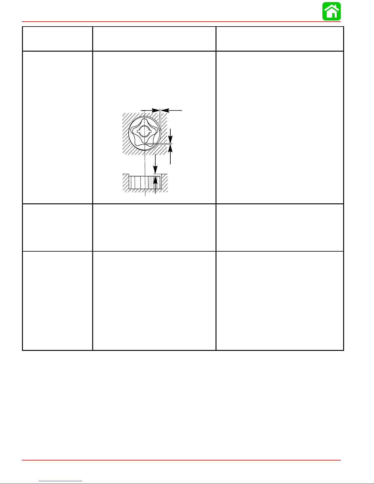
Propeller Removal/Installation
Standard Models
If the propeller shaft is rotated while the engine is in gear, there is the possibility that
the engine will crank over and start. T o prevent this type of accidental engine starting and possible serious injury caused from being struck by a rotating propeller,
always shift outboard to neutral position and remove spark plug leads when you
are servicing the propeller.
1. Shift outboard to neutral position.
GENERAL INFORMATION
WARNING
N
2. Remove the spark plug leads to prevent engine from starting.
N
3. Straighten the bent tabs on the tab washer.
90-828631R3 MARCH 1999 Page 1C-7
a
Page 39

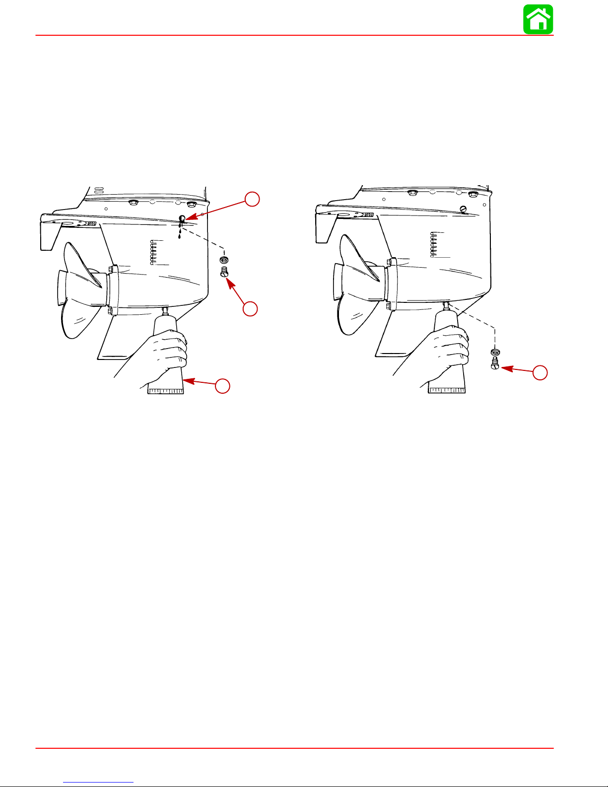
GENERAL INFORMATION
4. Place a block of wood between gear case and propeller to hold propeller and remove
propeller nut.
5. Pull propeller straight off shaft. If propeller is seized to the shaft and cannot be removed,
have the propeller removed by an authorized dealer.
6. Coat the propeller shaft with Quicksilver Anti-Corrosion Grease or 2-4-C Marine Lubricant with Teflon.
IMPORT ANT : To prevent the propeller hub from corroding and seizing to the propeller
shaft, especially in salt water, always apply a coat of the recommended lubricant to
the entire propeller shaft at the recommended maintenance intervals and also each
time the propeller is removed.
7. Flo-Torque I Drive Hub Propellers
d
a - Forward Thrust Hub
b - Propeller
c - Tab Washer
d - Propeller Nut
Page 1C-8 90-828631R3 MARCH 1999
c
a
b
Page 40

8. Flo-Torque II Drive Hub Propellers
f
GENERAL INFORMATION
e
a - Forward Thrust Hub
b - Propeller
c - Drive Sleeve
d - Rear Thrust Hub
e - Tab Washer
f - Propeller Nut
9. Place propeller nut retainer over pins. Place a block of wood between gear case and
propeller and tighten propeller nut to 55 lb-ft (75 Nm), aligning flat sides of the propeller
nut with tabs on the tab washer.
10. Secure propeller nut by bending tabs up and against the flats on the propeller nut.
c
d
a
b
b
a
a
b
a - Tab Washer Pins
b - Tabs
11. Reinstall spark plug leads.
Power Trim System
General Information
The power trim system is filled at the manufacturer and is ready for use.
Trim outboard through entire trim and tilt range several times to remove any air from the sys-
tem.
The trim system is pressurized and is not externally vented.
Power Trim Operation
With most boats, operating around the middle of the “trim” range will give satisfactory results. However, to take full advantage of the trimming capability there may be times when
you choose to trim your outboard all the way in or out. Along with an improvement in some
performance aspects comes a greater responsibility for the operator, and this is being aware
of some potential control hazards. The most significant control hazard is a pull or “torque”
that can be felt on the steering wheel or tiller handle. This steering torque results from the
outboard being trimmed so that the propeller shaft is not parallel to the water surface.
90-828631R3 MARCH 1999 Page 1C-9
Page 41

GENERAL INFORMATION
Avoid possible serious injury or death. When the outboard is trimmed in or out beyond a neutral steering condition, a pull on the steering wheel or tiller handle in either direction may result. Failure to keep a continuous firm grip on the steering
wheel or tiller handle when this condition exists can result in loss of boat control
as the outboard can turn freely . The boat can now “spin out” or go into a very tight
maximum turn which, if unexpected, can result in occupants being thrown within
the boat or out of the boat.
Consider the following lists carefully:
TRIMMING IN OR DOWN CAN:
1. Lower the bow.
2. Result in quicker planing off, especially with a heavy load or a stern heavy boat.
3. Generally improve the ride in choppy water.
4. Increase steering torque or pull to the right (with the normal right hand rotation
propeller).
5. In excess, lower the bow of some boats to a point where they begin to plow with their
bow in the water while on plane. This can result in an unexpected turn in either direction
called “bow steering” or “over steering” if any turn is attempted or if a significant wave
is encountered.
WARNING
Avoid possible serious injury or death. Adjust outboard to an intermediate trim position as soon as boat is on plane to avoid possible ejection due to boat spin-out.
Do not attempt to turn boat when on plane if outboard is trimmed extremely in or
down and there is a pull on the steering wheel or tiller handle.
TRIMMING OUT OR UP CAN:
1. Lift the bow higher out of the water.
2. Generally increase top speed.
3. Increase clearance over submerged objects or a shallow bottom.
4. Increase steering torque or pull to the left at a normal installation height (with the normal
right hand rotation propeller).
5. In excess, cause boat “porpoising” (bouncing) or propeller ventilation.
6. Cause engine overheating if any water intake holes are above the water line.
Trim “In” Angle Adjustment
Some outboard boats, particularly some bass boats, are built with a greater than normal
transom angle which will allow the outboard to be trimmed further “in” or “under”. This greater trim “under” capability is desirable to improve acceleration, reduce the angle and time
spent in a bow high boat, altitude during planing off, and in some cases, may be necessary
to plane off a boat with aft live wells, given the variety of available propellers and height
range of engine installations.
WARNING
However, once on plane, the engine should be trimmed to a more intermediate position to
a avoid a bow-down planing condition called “plowing”. Plowing can cause “bow steering”
or “over steering” and inefficiently consumes horsepower . In this condition, if attempting a
turn or encountering a diagonal, moderate wake, a more abrupt turn than intended may
result.
Page 1C-10 90-828631R3 MARCH 1999
Page 42

GENERAL INFORMATION
In rare circumstances, the owner may decide to limit the trim in. This can be accomplished
by repositioning the tilt stop pins into whatever adjustment holes in the transom brackets
is desired.
WARNING
Avoid possible serious injury or death. Adjust outboard to an intermediate trim position as soon as boat is on plane to avoid possible ejection due to boat spin-out.
Do not attempt to turn boat when on plane if outboard is trimmed extremely in or
down and there is a pull on the steering wheel or tiller handle.
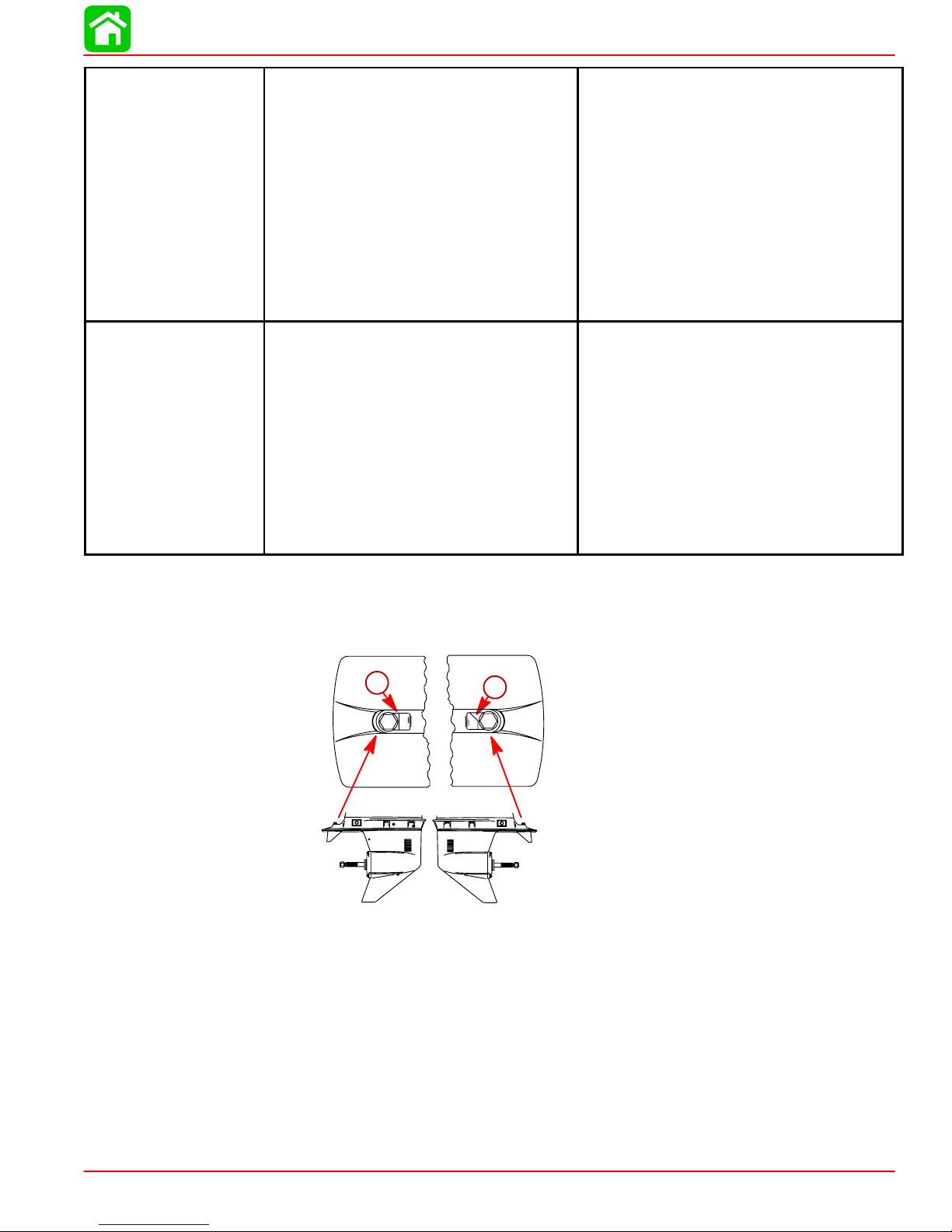
50 HP NON-BIGFOOT MODELS
a
a
a - Tilt Stop Pins
50 HP BIGFOOT MODELS
If an adjustment is required, purchase a stainless steel tilt pin (P/N 17-49930A1) and insert
it through whatever pin hole is desired. The non-stainless steel shipping bolt should not be
used in this application other than on a temporary basis.
a - Optional Tilt Pin
90-828631R3 MARCH 1999 Page 1C-11
a
28216
Page 43

GENERAL INFORMATION
Trim Tab Adjustment
Propeller steering torque will cause your boat to pull in one direction. This steering torque
is a normal thing that results from your outboard not being trimmed so the propeller shaft
is parallel to the water surface. The trim tab can help to compensate for this steering torque
in many cases and can be adjusted within limits to reduce any unequal steering effort.
NOTE: T rim tab adjustment will have little effect reducing steering torque if the outboard is
installed with the anti-ventilation plate approximately 2 inches (50mm) or more above the
boat bottom.
Operate your boat at normal cruising speed, trimmed to desired position. Turn your boat left
and right and note the direction the boat turns more easily.
If adjustment is necessary , loosen trim tab bolt and make small adjustments at a time. If the
boat turns more easily to the left, move the trailing edge of trim tab to the left. If the boat turns
more easily to the right move the trailing edge of trim tab to the right. Retighten bolt and
retest.
a
a - Trim Tab
Compression Check
1. Remove spark plugs.
2. Install compression gauge in spark plug hole.
3. Hold throttle plate at W.O.T.
4. Crank the engine over until the compression reading peaks on the gauge. Record the
reading.
5. Check and record compression of each cylinder. The highest and lowest reading
recorded should not differ by more than 15% (see example chart below). A reading
below 120 psi might indicate a total engine wear problem.
Example of compression test differences
Maximum (psi)
180 162
150 127.5
6. Compression check is important because an engine with low or uneven compression
cannot be tuned successfully to give peak performance. It is essential, therefore, that
improper compression be corrected before proceeding with an engine tuneup.
Minimum (psi)
7. Cylinder scoring: If powerhead shows any indication of overheating, such as discolored
or scorched paint, visually inspect cylinders for scoring or other damage as outlined in
Section 4 “Powerhead.”
Page 1C-12 90-828631R3 MARCH 1999
Page 44

Cylinder Leakage Testing
NOTE: Cylinder leakage testing*, along with compression testing, can help the mechanic
pinpoint the source of a mechanical failure by gauging the amount of leakage in an engine
cylinder. Refer to the manufactures tester instructions for proper testing procedures.
Cylinder Leakage Tester (Snap-On-Tools MT324)
GENERAL INFORMATION
* Courtesy of Snap-On-Tools
Analysis
NOTE: Spark plug hole is a 12 mm diameter. Use Snap-On-Tool MT26-18 adapter with
valve core removed.
Due to standard engine tolerances and engine wear, no cylinder will maintain a 0% of leakage. It is important only that cylinders have somewhat consistent reading between them.
Differences of 15 to 30% indicate excessive leakage. Larger engines tend to have a larger
percentage of cylinder leakage than smaller engines.
If excessive leakage is present, first check that the piston is at top dead center of its compression stroke. Leakage will naturally occur if the exhaust or intake valve is open.
T o determine the cause of high percentage leaks, you must locate where the air is escaping
from. Listen for air escaping thru the carburetor intake, adjacent spark plug holes, exhaust
pipe, crankcase fill plug. Use the following table to aid in locating the source of cylinder leakage:
Air Escaping From:
Carburetor Intake Valve
Exhaust System Exhaust Valve
Crankcase Fill Plug Piston or Rings
Adjacent Cylinders Head Gasket
Indicates Possible Defective:
90-828631R3 MARCH 1999 Page 1C-13
Page 45

GENERAL INFORMATION
Painting Procedures
Cleaning & Painting Aluminum Propellers & Gear Housings
WARNING
Avoid serious injury from flying debris. Avoid serious injury from airborne particles. Use eye and breathing protection with proper ventilation.
PROPELLERS
1. Sand the entire area to be painted with 3M 120 Regalite Polycut or coarse Scotch-Brite,
disc or belts.
2. Feather edges of all broken paint edges. Try not to sand through the primer.
3. Clean the surface to be painted using PPG Industries DX330 Wax and Grease Remover
or equivalent (Xylene or M.E.K.).
4. If bare metal has been exposed, use Quicksilver’s Light Gray Primer.
5. Allow a minimum of 1 hour dry time and no more than 1 week before applying the finish
coat.
6. Apply the finish coat using Quicksilver’s EDP Propeller Black.
GEAR HOUSINGS
The following procedures should be used in refinishing gear housings. This procedure will
provide the most durable paint system available in the field. The materials recommended
are of high quality and approximate marine requirements. The following procedure will provide a repaint job that compares with a properly applied factory paint finish. It is recommended that the listed materials be purchased from a local Ditzler Automotive Finish Supply
Outlet. The minimum package quantity of each material shown following is sufficient to refinish several gear housings.
Procedure:
1. Wash gear housing with a muriatic acid base cleaner to remove any type of marine
2. Wash gear housing with soap and water, then rinse.
3. Sand blistered area with 3M 180 grit sandpaper or P180 Gold Film Disc to remove paint
4. Clean gear housing thoroughly with (DX-330) wax and grease remover.
5. Spot repair surfaces where bare metal is exposed with (DX-503) alodine treatment.
IMPORT ANT : Do not use any type of aerosol spray paints as the paint will not properly
adhere to the surface nor will the coating be sufficiently thick to resist future paint
blistering.
growth, and rinse with water, if necessary.
blisters only. Feather edge all broken paint edges.
6. Mix epoxy chromate primer (DP-40) with equal part catalyst (DP-401) per manufacturers instructions, allowing proper induction period for permeation of the epoxy primer and
catalyst.
7. Allow a minimum of one hour drying time and no more than one week before top coating
assemblies.
8. Use Ditzler Urethane DU9000 for Mercury Black, DU34334 for Mariner Grey, and
DU35466 for Force Charcoal, and DU33414M for Sea Ray White. Catalyze all four colors with Ditzler DU5 catalyst mixed 1:1 ratio. Reduce with solvents per Ditzler label.
Page 1C-14 90-828631R3 MARCH 1999
Page 46

Be sure to comply with instructions on the label for ventilation and respirators. Using a spray gun, apply one half to one mil even film thickness. Let dry , flash off for
five minutes and apply another even coat of one half to one mil film thickness. This
urethane paint will dry to the touch in a matter of hours, but will remain sensitive
to scratches and abrasions for a few days.
9. The type of spray gun used will determine the proper reduction ratio of the paint.
IMPORTANT: Do not paint sacrificial zinc trim tab or zinc anode.
10. Cut out a cardboard “plug” for trim tab pocket to keep paint off of mating surface to main-
tain good continuity circuitry between trim tab and gear housing.
Decal Application
Decal Removal
1. Mark decal location before removal to assure proper alignment of new decal.
2. Carefully soften decal and decal adhesive with a heat gun or heat blower while removing
old decal.
3. Clean decal contact area with a 1:1 mixture of isopropyl alcohol and water.
GENERAL INFORMATION
CAUTION
4. Thoroughly dry decal contact area and check for a completely cleaned surface.
Instructions for “Wet” Application
NOTE: The following decal installation instructions are provided for a “Wet” installation. All
decals should be applied wet.
TOOLS REQUIRED
1. Plastic Squeegee*
2. Stick Pin
3. Dish Washing Liquid/Detergent without ammonia** “Joy” and “Drift” are known to be
compatible for this process.
** Automotive Body Filler Squeegee
** Do not use a soap that contains petroleum based solvents.
SERVICE TIP: Placement of decals using the “Wet” application will allow time to position decal. Read entire installation instructions on this technique before proceeding.
TEMPERA TURE
IMPORT ANT : Installation of vinyl decals should not be attempted while in direct sunlight. Air and surface temperature should be between 60°F (15°C) and 100°F (38°C)
for best application.
SURFACE PREPARATION
IMPORT ANT : Do not use a soap or any petroleum based solvents to clean application
surface.
Clean entire application surface with mild dish washing liquid and water. Rinse surface thoroughly with clean water.
90-828631R3 MARCH 1999 Page 1C-15
Page 47

GENERAL INFORMATION
DECAL APPLICATION
1. Mix 1/2 ounce (16 ml) of dish washing liquid in one gallon (4 l) of cool water to use as
wetting solution.
NOTE: Leave protective masking, if present, on the face of decal until final steps of decal
installation. This will ensure that the vinyl decal keeps its shape during installation.
2. Place the decal face down on a clean work surface and remove the paper backing from
“adhesive side” of decal.
3. Using a spray bottle, flood the entire “adhesive side” of the decal with the pre-mixed wetting solution.
4. Flood area where the decal will be positioned with wetting solution.
5. Position pre-wetted decal on wetted surface and slide into position.
6. Starting at the center of the decal, “lightly” squeegee out the air bubbles and wetting
solution with overlapping strokes to the outer edge of the decal. Continue going over the
decal surface until all wrinkles are gone and adhesive bonds to the cowl surface.
7. Wipe decal surface with soft paper towel or cloth.
8. Wait 10 - 15 minutes.
9. Starting at one corner, “carefully and slowly” pull the masking off the decal surface at
a 180° angle.
NOTE: To remove any remaining bubbles, pierce the decal at one end of the bubble with
stick pin and press out the entrapped air or wetting solution with your thumb (moving toward
the puncture).
Page 1C-16 90-828631R3 MARCH 1999
Page 48

OUTBOARD MOTOR INSTALLATION
IMPORTANT INFORMATION
Section 1D - Outboard Motor Installation
Table of Contents
Electric Fuel Pump 1D-1. . . . . . . . . . . . . . . . . . . . . . . .
Boat Horsepower Capacity 1D-1. . . . . . . . . . . . . . . . .
Start in Gear Protection 1D-2. . . . . . . . . . . . . . . . . . . .
Selecting Accessories For The Outboard 1D-2. . . . .
Installation Specifications 1D-2. . . . . . . . . . . . . . . . . . .
Lifting Outboard 1D-3. . . . . . . . . . . . . . . . . . . . . . . . . . .
Steering Cable 1D-3. . . . . . . . . . . . . . . . . . . . . . . . . . . .
Steering Cable Seal 1D-4. . . . . . . . . . . . . . . . . . . . . . .
Steering Link Rod 1D-4. . . . . . . . . . . . . . . . . . . . . . . . .
Installing Outboard – Thumb Screw Models 1D-5. . .
Installing Outboard – Non Thumb
Screw Models 1D-6. . . . . . . . . . . . . . . . . . . . . . . . . . . .
Electric Fuel Pump
If an electric fuel pump is used, the fuel pressure must not exceed 4 psi at the engine. If necessary, install a pressure regulator to regulate the pressure.
1
D
Wiring Harness 1D-7. . . . . . . . . . . . . . . . . . . . . . . . . . .
Battery Cable Connections 1D-8. . . . . . . . . . . . . . . . .
Single Outboards 1D-8. . . . . . . . . . . . . . . . . . . . . . .
Dual outboards 1D-8. . . . . . . . . . . . . . . . . . . . . . . . .
Shift and Throttle Cable 45 and 50 hp Models 1D-9.
45-50 hp - Shift Cable Installation 1D-9. . . . . . . .
45-50 hp - Throttle Cable Installation 1D-11. . . . .
Trim-In Stop Adjustment – Power
Trim Models 1D-13. . . . . . . . . . . . . . . . . . . . . . . . . . . . .
Trim Tab Adjustment 1D-13. . . . . . . . . . . . . . . . . . . . . .
Boat Horsepower Capacity
U.S. COAST GUARD CAPACITY
MAXIMUM HORSEPOWER XXX
MAXIMUM PERSON
CAPACITY (POUNDS) XXX
MAXIMUM WEIGHT
CAPACITY XXX
Do not overpower or overload the boat. Most boats will carry a required capacity plate indicating the maximum acceptable power and load as determined by the manufacturer following certain federal guidelines. If in doubt, contact your dealer or the boat manufacturer.
Using an outboard that exceeds the maximum horsepower limit of a boat can: 1.
cause loss of boat control 2. place too much weight at the transom, altering the designed flotation characteristics of the boat or 3. cause the boat to break apart, particularly around the transom area. Overpowering a boat can result in serious injury ,
death, or boat damage.
WARNING
90-828631R3 MARCH 1999 Page 1D-1
Page 49

OUTBOARD MOTOR INSTALLATION
Start in Gear Protection
The remote control connected to the outboard must be equipped with a start-in-gear protection device. This prevents the engine from starting in gear.
WARNING
Avoid serious injury or death from a sudden unexpected acceleration when starting
your engine. The design of this outboard requires that the remote control used with
it must have a built in start-in-gear protection device.
Selecting Accessories For The Outboard
Genuine Quicksilver Parts and Accessories have been specifically designed and tested for
this outboard.
Some accessories not manufactured or sold by Quicksilver are not designed to be safely
used with this outboard or outboard operating system. Acquire and read the Installation, Operation, and Maintenance manuals for all selected accessories.
Installation Specifications
a
Transom Opening “a” (Minimum)
Single Engine (Remote) 19 in. (483 mm)
Single Engine (Tiller) 30 in. (762 mm)
a
b
Dual Engines 40 in. (1016 mm)
Engine Center Line For Dual Engines “b” (Minimum)
Page 1D-2 90-828631R3 MARCH 1999
22 1/2 in. (572 mm)
Page 50

Lifting Outboard
1. Use lifting eye on engine.
Steering Cable
STARBOARD SIDE ROUTED CABLE
OUTBOARD MOTOR INSTALLATION
1. Lubricate the entire cable end with 2-4-C Lubricant with Teflon.
95
95
2. Insert steering cable into tilt tube.
3. Torque nut to specified torque.
2-4-C w/Teflon (92-850736A1)
90-828631R3 MARCH 1999 Page 1D-3
Nut Torque
35 lb-ft (47.5 Nm)
Page 51

OUTBOARD MOTOR INSTALLATION
Steering Cable Seal
1. Mark tilt tube 1/4 in. (6.4 mm) from end. Install seal components.
2. Thread cap to the mark.
b
a
a-1/4 in. (6.4 mm) Mark
b-Plastic Spacer
c-O-Ring Seal
d-Cap
Steering Link Rod
1. Install steering link rod per illustration.
1/4 in. (6.4 mm)
c
d
b
f
d
e
c
a
a-Special Bolt (10-90041) Torque to 20 lb-ft (27.1 Nm)
b-Nylon Insert Locknut (11-34863) Torque to 20 lb-ft (27.1 Nm)
c-Spacer (12-71970)
d-Flat Washer (2)
e-Nylon Insert Locknut (11-34863) Tighten Locknut Until it Seats, Then Back Nut
Off 1/4 Turn
f-Use Middle Hole
IMPORTANT: The steering link rod that connects the steering cable to the engine
must be fastened using special bolt (“a” - Part Number 10-90041) and self locking
nuts (“b” & “e” - Part Number 11-34863). These locknuts must never be replaced with
common nuts (non locking) as they will work loose and vibrate off, freeing the link
rod to disengage.
Disengagement of a steering link rod can result in the boat taking a full, sudden,
sharp turn. This potentially violent action can cause occupants to be thrown overboard exposing them to serious injury or death.
Page 1D-4 90-828631R3 MARCH 1999
WARNING
Page 52

Installing Outboard – Thumb Screw Models
WARNING
Outboard must be fastened to boat transom one of two ways: 1. permanently fastened to transom with thumb screws, and mounting bolts (provided), or 2. secured
to the transom using the optional outboard mounting kit (shown below). Should the
outboard strike an underwater object or be steered into a sharp turn, failure to fasten outboard correctly to the boat transom with mounting bolts or optional mounting kit could result in outboard ejecting suddenly off boat transom causing serious
injury, death, boat damage, or loss of outboard.
IMPORT ANT: Optional outboard mounting kits shown, must be used if outboard will
not be permanently fastened to the transom with mounting bolts.
a
OUTBOARD MOTOR INSTALLATION
a-Outboard Mounting Kit Part No. 812432A4
1. Center outboard on the transom. Install the outboard so that the anti-ventilation plate
is in line or within 1 in. (25 mm) below the bottom of the boat.
a
0 - 1 in.
(0 - 25 mm)
a-Anti-Ventilation Plate
2. Fasten outboard with provided mounting hardware shown.
3. Mark and drill two 17/32 in. (13.5 mm) lower mounting holes.
e
c
d
a-1/2 in. Diameter Bolts (2)
b-Flat Washers
c-Locknuts
d-Marine Sealer - Apply to Shanks of Bolts, Not Threads
e-Thumb Screws - Tighten Securely
90-828631R3 MARCH 1999 Page 1D-5
b
a
Page 53

OUTBOARD MOTOR INSTALLATION
Installing Outboard – Non Thumb Screw Models
1. Attach (tape) engine mounting template (located in this manual) to boat transom.
2. Mark and drill four 17/32 in. (13.5 mm) mounting holes.
3. Install the outboard so that the anti-ventilation plate is in-line or within 1 in. (25 mm) below the bottom of the boat.
a
0 - 1 in.
(0 - 25 mm)
a-Anti-Ventilation Plate
4. Fasten outboard with provided mounting hardware shown.
d
d
c
b
a-1/2 in. Diameter Bolts (2)
b-Flat Washers
c-Locknuts
d-Marine Sealer - Apply to Shanks of Bolts, Not Threads
Page 1D-6 90-828631R3 MARCH 1999
c
b
a
a
Page 54

Wiring Harness
IMPORT ANT: Warning Horn Requirement – The remote control or key switch assembly must be wired with a warning horn. This warning horn is used with the engine
warning system.
1. Route wiring harness into bottom cowl.
2. Connect wiring. Place harness into the holder.
OUTBOARD MOTOR INSTALLATION
BLU/WHT
GRN/WHT
TAN
BRN/WHT
BLU/WHT
GRN/WHT
a
a-Power Trim Connections
b-Holder – Place Harness Into Holder
b
90-828631R3 MARCH 1999 Page 1D-7
Page 55

OUTBOARD MOTOR INSTALLATION
Battery Cable Connections
Single Outboards
a
(+)
b
Dual outboards
1. Connect a common ground cable (wire size same as engine battery cables) between
(–)
a-Red Sleeve (Positive)
b-Black Sleeve (Negative)
c-Starting Battery
negative (–) terminals on starting batteries.
(–)
c
a
a-Ground Cable (Same Wire Size As Engine Battery Cable) – Connect Between
Negative (–) Terminals
Page 1D-8 90-828631R3 MARCH 1999
(–)
Page 56

Shift and Throttle Cable 45 and 50 hp Models
Install cables into the remote control following the instructions provided with the remote control.
NOTE: Install the shift cable to the engine first. The shift cable is the first cable to move when
the remote control handle is moved out of neutral.
45-50 hp - Shift Cable Installation
1. Position remote control into neutral.
N
2. Shift outboard into neutral.
3. Measure the distance between pin and center of lower hole.
OUTBOARD MOTOR INSTALLATION
a
c
b
a-Distance Between Pin And Center of Lower Hole
b-Pin
c-Lower Hole
4. Fit shift cable through rubber grommet.
a-Shift Cable
90-828631R3 MARCH 1999 Page 1D-9
a
Page 57

OUTBOARD MOTOR INSTALLATION
5. Push in on the cable end until resistance is felt.
6. While pushing in on the cable end, adjust the cable barrel to attain the measured distance taken in Step 3.
a
b
a-Adjust Cable Barrel To Attain The Measured Distance Taken In Step 3
b-Cable Barrel
7. Place cable barrel into the barrel holder. Fasten cable to pin with retainer.
a
b
a-Place Barrel Into Barrel Holder
b-Retainer
8. Check shift cable adjustments as follows:
a. Shift remote control into forward. The propeller shaft should be locked in gear. If not,
adjust the barrel closer to the cable end.
b. Shift remote control into neutral. The propeller shaft should turn freely without drag.
If not, adjust the barrel away from the cable end. Repeat steps a and b.
c. Shift remote control into reverse while turning propeller. The propeller shaft should
be locked in gear. If not, adjust the barrel away from the cable end. Repeat steps a
thru c.
d. Shift remote control back to neutral. The propeller shaft should turn freely without
drag. If not, adjust the barrel closer to the cable end. Repeat steps a thru d.
Page 1D-10 90-828631R3 MARCH 1999
Page 58

45-50 hp - Throttle Cable Installation
1. Position remote control into neutral.
N
2. Fit throttle cable through rubber grommet.
a
a-Throttle Cable
OUTBOARD MOTOR INSTALLATION
3. Install throttle cable with retainer pin. Lock retainer pin in place.
b
a-Throttle Cable
b-Retainer Pin
a
90-828631R3 MARCH 1999 Page 1D-11
Page 59

OUTBOARD MOTOR INSTALLATION
4. Move the throttle linkage arm down.
a-Throttle Linkage Arm
5. While holding down the throttle linkage arm (“a” Step 4), adjust the throttle barrel until
a 1/8 in. (3.2 mm) gap exists between the oval shaped boss and the cam.
a
1/8 in. (3.2 mm)
b
a-Throttle Barrel
b-Oval Shaped Boss
c-Cam
c
a
Page 1D-12 90-828631R3 MARCH 1999
Page 60

OUTBOARD MOTOR INSTALLATION
6. Fasten control cables with the cable latch.
IMPORT ANT: After installation, move the remote control handle a few times from the
neutral position to the wide-open-throttle position in forward gear. Move handle back
to neutral and repeat Step 6. Visually Check for the specified gap between the oval
shaped boss and the throttle cam. If necessary, readjust the barrel.
Trim-In Stop Adjustment – Power Trim Models
If an adjustment is required, purchase a stainless steel tilt pin (P/N 17-49930A1) and insert
it through whatever pin hole is desired. The non-stainless steel shipping bolt should not be
used in this application other than on a temporary basis.
a-Tilt Pin
Trim Tab Adjustment
The trim tab can be adjusted within limits to help compensate for steering torque.
Adjust trim tab as follows:
• If boat tends to pull to the right, move the rear edge of the trim tab to the right.
a
90-828631R3 MARCH 1999 Page 1D-13
Page 61

OUTBOARD MOTOR INSTALLATION
• If boat tends to pull to the left, move the rear edge of the trim tab to the left.
NOTE: T rim tab adjustment will have little effect reducing steering torque if the anti-ventilation plate is raised 2 inches (50 mm) or more above the boat bottom.
Page 1D-14 90-828631R3 MARCH 1999
Page 62

Table of Contents
IGNITION
ELECTRICAL
Section 2A - Ignition
2
Specifications 2A-2. . . . . . . . . . . . . . . . . . . . . . . . . . .
Special Tools 2A-3. . . . . . . . . . . . . . . . . . . . . . . . . . .
Flywheel 2A-4. . . . . . . . . . . . . . . . . . . . . . . . . . . . . . .
Flywheel 2A-5. . . . . . . . . . . . . . . . . . . . . . . . . . . . . . .
Electrical Components 2A-6. . . . . . . . . . . . . . . . . . .
Electrical Components 2A-7. . . . . . . . . . . . . . . . . . .
Ignition Description 2A-8. . . . . . . . . . . . . . . . . . . . . .
Ignition Component Description 2A-8. . . . . . . . . . .
Capacitor Discharge Unit (CDI) 2A-8. . . . . . . . .
Trigger Coil 2A-9. . . . . . . . . . . . . . . . . . . . . . . . . .
Stator Assembly 2A-9. . . . . . . . . . . . . . . . . . . . . .
Flywheel Assembly 2A-10. . . . . . . . . . . . . . . . . . .
Ignition Coil 2A-10. . . . . . . . . . . . . . . . . . . . . . . . . .
Ignition Test Procedures 2A-11. . . . . . . . . . . . . . . . . .
Direct Voltage Adapter (DVA) 2A-11. . . . . . . . . .
Ignition Troubleshooting 2A-12. . . . . . . . . . . . . . . . . .
Tool: Multimeter/DVA Tester 91-99750A1 2A-12
Ignition Diagnostic Procedures 2A-13. . . . . . . . . . . .
Suggested Testing Procedures 2A-13. . . . . . .
*Recommended Test 2A-13. . . . . . . . . . . . . . . . . .
Testing Ignition Components 2A-15. . . . . . . . . . . . . .
Resistance Tests 2A-15. . . . . . . . . . . . . . . . . . . . .
Trigger Coil Test 2A-15. . . . . . . . . . . . . . . . . . .
Stator Test (Ignition Charge Coil) 2A-16. . . .
Lighting Coil 2A-16. . . . . . . . . . . . . . . . . . . . . .
Ignition Coil (Primary) 2A-17. . . . . . . . . . . . . .
Spark Plug cap Removal 2A-17. . . . . . . . . . .
Ignition Coil (Secondary) 2A-17. . . . . . . . . . .
Spark Plug Cap Resistor Test 2A-18. . . . . . .
Thermo Switch 2A-18. . . . . . . . . . . . . . . . . . . .
Flywheel Removal and Installation 2A-19. . . . . . . . .
Flywheel Removal 2A-19. . . . . . . . . . . . . . . . . . . .
Flywheel Installation 2A-20. . . . . . . . . . . . . . . . . .
Flywheel without load ring & Spacer 2A-20.
Flywheel with load ring & Spacer 2A-21. . . .
(CDI) Unit Removal and Installation 2A-22. . . . . . . .
Ignition Coil Removal and Installation 2A-23. . . . . .
Rectifier Removal and Installation 2A-24. . . . . . . . .
Stator Removal and Installation 2A-25. . . . . . . . . . .
Trigger Coil Removal and Installation 2A-26. . . . . .
A
90-828631R3 MARCH 1999 Page 2A-1
Page 63

IGNITION
Specifications
IGNITION SYSTEM*
*Readings taken @ 68°F
(20°C).
Type
Spark Plug Type (NGK)
Spark Plug Gap
Firing Order
Ignition Timing:
40/45 hp
Fully Retarded
Fully Advanced (2500-3000 rpm)
50 hp
Fully Retarded
Fully Advanced (2500-3000 rpm)
Charge Coil Resistance
Trigger Coil Resistance
Ignition Coil Resistance:
Primary
Secondary
C.D.I. Engine Speed Limiter
C.D.I. Overheat Speed Control
Engine Temperature Switch
Above 131° F (55° C)
Below 104° F (40° C)
Capacitor Discharge Ignition
NGK DPR6EA-9
0.035 in. (1.0 mm)
1-3-4-2
5° B.T.D.C
25° B.T.D.C
5° B.T.D.C
35° B.T.D.C
272 - 408 Ω (BRN-BLU)
396 - 594 Ω (WHT/BLK-WHT/RED)
0.1 - 0.7 Ω
3.5 - 4.7 kΩ
6120 - 6280 rpm
1600 - 2400 rpm
No Continuity
Continuity
Page 2A-2 90-828631R3 MARCH 1999
Page 64

Special Tools
1. Flywheel Holder P/N 91-83163M.
2. Flywheel Puller P/N 91-83164M.
IGNITION
90-828631R3 MARCH 1999 Page 2A-3
Page 65

IGNITION
Flywheel
17
19
18
1
4
3
2
5
8
6
12
51
11
13
7
9
10
16
15
14
110
Page 2A-4 90-828631R3 MARCH 1999
51
Loctite “222” Small Screw Threadlocker (92-809818)
110
4-stroke Outboard Oil (92-828000A12)
Page 66

IGNITION
REF
Flywheel
.
QTY. DESCRIPTION lb-in. lb-ft Nm
NO.
1 1 COVER
2 2 GROMMET
3 1 TUBING (19 IN.)
4 2 DAMPER
5 1 NUT 116 157
6 1 WASHER
7 1 FLYWHEEL
8 1 DECAL-W arning Spinning flywheel
9 3 SCREW (M6 x 25) 75 8.5
10 1 STATOR
11 1 BASE–Stator
12 2 SCREW 100 11.5
13 2 PIN
14 1 KEY
15 1 COIL–Pulser
16 2 SCREW (M5 x 10) 45 5.0
17 1 DECAL-Warning Neutral
18 1 DECAL-Engine Oil/Valve clearance
19 1 DECAL-EPA INFO (1999)(SEE NOTE)
NOTE: THE EPA LABEL HAS IMPORTANT INFORMATION ON EPA EMISSION REGULATIONS. REPLACE ANY
MISSING OR UNREADABLE EPA LABEL.
TORQUE
90-828631R3 MARCH 1999 Page 2A-5
Page 67

IGNITION
Electrical Components
NOTE: APPLY LIQUID NEOPRENE TO ALL EYELET WIRING TERMINAL CONNECTIONS.
6
2
1
14
17
3
6
14
17
15
6
16
18
7
8
5
13
9
23
21
22
20
19
10
9
4
24
12
6
11
27
30
24
32
29
25
26
6
9
Page 2A-6 90-828631R3 MARCH 1999
Dielectric Grease (92-823506--1)
Loctite PST Pipe Sealant (92-809822)
31
28
Page 68

IGNITION
REF
2
23
26
Electrical Components
.
QTY. DESCRIPTION lb-in. lb-ft Nm
NO.
1 2 SCREW (M6 x 25) 100 11.5
1 ELECTRIC CONTROLLER (50)
1 ELECTRIC CONTROLLER (4045)
3 1 BRACKET (NON-BIGFOOT)
4 1 BRACKET (BIGFOOT)
5 4 SCREW (M8 x 35) 210 17.5 23.7
6 1 SOLENOID PLATE
7 1 SCREW (M6 x 16) 75 8.5
8 2 NUT 30 3.5
9 1 STAR TER SOLENOID
10 1 BRACKET
11 1 VOLTAGE REGULAT OR
12 2 SCREW (M6 x 25) 100 11.5
13 1 PRESSURE SWITCH 75 8.5
14 2 PLATE
15 1 TEMPERATURE SWITCH
16 1 TEMPERATURE SWITCH
17 2 SCREW (M6 x 13) 75 8.5
18 4 GROMMET
19 4 HI–TENSION CABLE
20 4 SP ARK PLUG 150 12.5 17
21 2 IGNITION COIL
22 4 SCREW (M6 x 30) 75 8.5
1 DECAL-(Coil Identification #1)
1 DECAL-(Coil Identification #2)
1 DECAL-(Coil Identification #3)
1 DECAL-(Coil Identification #4)
24 1 ENGINE WIRING HARNESS
25 1 FUSE
1 SCREW (M5 x 10) (NON-BIGFOOT) 30 3.5
1 SCREW (M6 x 13) (BIGFOOT) 30 3.5
27 1 SCREW (M6 x 13)
28 AR STA–STRAP
29 1 BATTERY CABLE (NEGATIVE)
30 1 INSULATOR BOOT
31 BATTERY CABLE (POSITIVE)
32 1 HARNESS–Auxiliary (HANDLE)
TORQUE
90-828631R3 MARCH 1999 Page 2A-7
Page 69

IGNITION
Ignition Description
The ignition system uses CDI (Capacitor Discharge Ignition). This system provides quick
voltage buildup and strong spark required for high power and high performance engines.
The CDI ignition system does not incorporate mechanically operated points, therefor making this CDI unit virtually maintenance free.
As the flywheel rotates, electrical power (alternating current) is produced by the capacitor
charging coil. This power is rectified by diodes so that direct current voltage is utilized by
the ignition system. When the silicone controlled rectifier (SCR) is off, the D.C. voltage is
stored by the capacitor.
As the flywheel rotates 360°from the point at which charging of the system began, the trigger coil produces voltage which is rectified and applied to the (SCR) gate.
This gate signal then turns on the (SCR) and the stored voltage is shorted to ground thru
the primary winding of the ignition coil.
The voltage discharged to the primary winding of the ignition coil causes a surge of high voltage to be induced in the secondary winding of the ignition coil. This induced voltage of sufficient amplitude causes the spark plugs to fire.
The voltage stored by the capacitor holds the (SCR) on until the ignition coil current is discharged. Then once the capacitor has discharged, the (SCR) turns off and the ignition cycle
is repeated.
Actuating the stop switch shorts the power being produced by the charge coil to ground. This
prevents charging of the capacitor and thus stops spark plug firing.
Ignition Component Description
Capacitor Discharge Unit (CDI)
a
a-Ignition CDI Unit (Capacitor Discharge Ignition)
Under normal operating conditions the CDI unit controls the following:
1. Control ignition spark timing by monitoring the trigger pulses.
2. Maintains an idle timing of 5° BTDC.
3. Advances spark timing quickly to 35° BTDC under hard acceleration conditions.
4. Limits rpm of the engine to 2000 rpm in the event of low oil pressure conditions.
5. Limits rpm of the engine to 2000 rpm in the event of overheat condition.
6. Limits rpm of the engine in the event of over-speed (@ 6200 rpm).
NOTE: The CDI unit controls all timing operations. There is no timing adjustment required
on this outboard engine.
Page 2A-8 90-828631R3 MARCH 1999
Page 70

Trigger Coil
A single wound coil with magnet core mounted to one side of the stator mounting base. The
trigger is positioned on the outside of the flywheel assembly and is charged when a raised
boss on the flywheel passes the trigger/magnet winding. A pulse voltage is then sent to an
(SCR) switch within the CDI unit. The trigger is mounted in a fixed timing position.
Stator Assembly
IGNITION
a
12
a-Trigger Coil
b
a
3
12
12
a-Ignition Charge Coil
b-Lighting System Coils and Electrothermal Valve Coils
The stator assembly located under the flywheel contains the Ignition Charge Coils, and lighting system Coils. All of these coils make up the stator assembly.
As the flywheel permanent magnets pass the respective stator coil windings, an AC pulse
current is produced at each coil winding when magnet polarity changes. (South to North),
(North to South) etc.
90-828631R3 MARCH 1999 Page 2A-9
Page 71

IGNITION
Flywheel Assembly
The flywheel assembly contains one permanently charged magnet which is bonded and
retained to the inner wall of the flywheel. This magnet is segmented with 3 positive and 3
negative poles. (12 pole) (6 positive pulses per revolution).
Ignition Coil
a
a-Ignition Coil and High Tension Lead Assembly
The primary (+) side of the ignition coil receives voltage discharged from a capacitor in the
ignition (CDI) unit. The voltage is multiplied by the coil until it can jump the spark plug gap.
The ignition coil will produce a high voltage current each crankshaft revolution, producing
a spark at each cylinder at the same time (Waisted Spark Ignition). Ignition coil maximum
output is approximately 40,000 volts.
Page 2A-10 90-828631R3 MARCH 1999
Page 72

Ignition Test Procedures
Direct Voltage Adapter (DVA)
DANGER – HIGH VOLTAGE/SHOCK HAZARD! Do not touch ignition components
and/or metal test probes while engine is running and/or being “cranked”. STAY
CLEAR OF SP ARK PLUG LEADS. To assure personal safety, each individual spark
plug lead should be grounded to engine.
When testing or servicing the ignition system, high voltage is present. DO NOT
TOUCH OR DISCONNECT any ignition parts while engine is running, while key
switch is on or while battery cables are connected.
Failure to comply with the following items may result in damage to the ignition system.
1. DO NOT reverse battery cable connections. The battery negative cable is (–) ground.
IGNITION
WARNING
WARNING
CAUTION
2. DO NOT “spark” battery terminals with battery cable connections to check polarity.
3. DO NOT disconnect battery cables while engine is running.
4. DO NOT crank engine with CDI or Ignition Coils not grounded.
CAUTION
T o protect against meter and/or component damage, observe the following precautions:
• 400 VDC* test position (or higher) MUST BE used for all tests.
• INSURE the Positive (+) lead/terminal of DV A is connected to the Positive (+) receptacle
of meter.
• DO NOT CHANGE meter selector switch position while engine is running and/or being
“cranked”.
• ALL COMPONENTS MUST BE GROUNDED during tests. Running or “cranking” engine with CDI or Ignition Coils ungrounded may damage components.
* If using a meter with a built-in DV A, the DV A/400 or DVA/500 VDC test position should be
used.
NOTE: T est leads are not supplied with the Direct V oltage Adapter. Use test leads supplied
with multi meter.
Test procedures and specifications are provided for checking primary ignition voltage
while the engine is running and/or being “cranked” with all harnesses connected.
90-828631R3 MARCH 1999 Page 2A-1 1
Page 73

IGNITION
Ignition Troubleshooting
DANGER - HIGH VOLTAGE/SHOCK HAZARD! Do not touch ignition components
and/or metal test probes while engine is running and/or being “cranked”. STAY
CLEAR OF SP ARK PLUG LEADS. To assure personal safety, each individual spark
plug lead should be grounded to engine.
When testing or servicing the ignition system, high voltage is present. DO NOT
TOUCH OR DISCONNECT any ignition parts while engine is running.
Tool: Multimeter/DVA Tester 91-99750A1
WARNING
WARNING
Component
Test
Coil
Primary
Stator Charge Coil 400 DVA* Brown (Br) Lead (2) Ground 160 - 280 (1)
(CDI) Unit
Stop Circuit
Selector Switch
Position
400 DVA*
20 DVA
* If using a meter that requires a DV A adapter, place selector switch to the 400 VDC position.
** Reverse Polarity
(1) Readings may vary at cranking speed or at idle speed.
(2) Back probe the electrical lead bullet connector in order to make connection.
DVA Lead
Red
Coil (–) Black (B)
(2) **
Lead
(CDI) Unit
White (W) Lead
(2)
DVA Lead
Black
Coil (+) Orange
(O) Lead
Ground 3 - 7
(2) **
Voltage Reading
@300-3000 RPM
160 - 280 (1)
Multimeter Ohm Checks
Tested Part Multimeter Wires Connected To: Meter Scale Meter Reading
Stator Charge Coil
Trigger Coil
Ignition Coil Primary
(with wires
disconnected)
Ignition Coil Secondary
(test with coil leads dis-
connected and the
high tension lead cap
removed)***
Red
Black
Red
Black
Red
Black
Red
Black
Blue (2)
Brown (1)
White/Red (1)
White/Blk (2)
Orange (O)
Black (B)
High Tension Lead
#1
High Tension Lead
#2
R x 1 Ω 272 - 408
R x 1 Ω 396 - 594
R x 1 Ω 0.1 - 0.7
k Ω 3.5 - 5.2
(1)
NOTE: Copper is an excellent conductor, however, resistance may notably vary between
low and high temperature. Therefore, reasonable differences can be accepted between
resistance readings and specifications. The above readings are for a cold (room temperature) engine. Resistance will increase if the engine is warm.
*** High tension lead cap contain a 5k ohm resister . Remove caps when making secondary
ignition coil test.
Page 2A-12 90-828631R3 MARCH 1999
Page 74

Ignition Diagnostic Procedures
TROUBLESHOOTING TIP: With engine running, use inductive timing light to check spark
advance of each cylinder as throttle is opened and closed. If timing advances and retards
on each cylinder, ignition system is MOST LIKELY functioning properly.
IMPORTANT: If outboard appears to have an ignition system failure, it is recommended that before beginning in-depth troubleshooting:
• Ensure that the engine is mechanically sound condition. (Fuel System, Cylinder Compression etc.)
• Check all engine ground leads for loose or corroded connections.
• Disconnect and reconnect ignition harness connectors to verify proper continuity.
SUGGESTED TESTING PROCEDURES
NOTE: The following recommended tests and probable causes are not listed in any specific
order. The technician should use this table as a guide to help isolate and test the specific
problem/condition. Always perform the DVA tests first (if applicable), then perform resistance test to validate suspected component failure.
IGNITION
*Recommended Test
(1) DVA TEST (Direct Voltage Adapter)
(2) OHM TEST (Resistance Testing)
(3) Replace Component and Retest
(4) Mechanical Test/Repair
PROBLEM/CONDITION
No Spark Condition (Both Cylinders) Trigger
Stator
(CDI) Unit
Stop Circuit Short to Ground:
a - stop circuit lead
b - lanyard stop switch
c - tiller handle stop button
d- remote control harness
Ignition Coil
Spark Plugs
Open Ground Condition:
a - ignition coil
b - (CDI) unit
c - stator ground
No Spark Condition (One Cylinder) High Tension Lead
Spark Plug Cap (Resistor)
Spark Plug
Probable Cause *Perform
Test No.
2
1-2
1-3
2
2
2
2
2
3
2
3
2
2
2
3
90-828631R3 MARCH 1999 Page 2A-13
Page 75

IGNITION
Weak Spark Condition
(Low Primary Voltage)
Timing Fluctuates
Note: It is considered normal for the timing
to fluctuate approximately 1° - 2° within the
designated timing window.
*Recommended Test (cont.)
(1) DVA TEST (Direct Voltage Adapter)
(2) OHM TEST (Resistance Testing)
(3) Replace Component and Retest
(4) Mechanical Test/Repair
Ground Connection at:
a - ignition coil
b - (CDI) unit
c - stator
High Resistance To Ground at:
a - stop/lanyard switch (water/corrosion)
Weak Charge Coil
(CDI) Unit Failure
Ignition Coil/High Tension Lead(s)
Spark Plug(s)
Spark Plug Cap (Resistor)
Loss Of Oil Pressure:
a - timing retards and fluctuates, rpm will
drop below 2000 rpm
Flywheel Key Sheared
(CDI) Unit
2
2
2
2
1-2
1-3
2
3
2
4
4
3
PROBLEM/CONDITION
Probable Cause *Perform
Timing Will Not Advance Low Oil Pressure:
a - timing retards and fluctuates, rpm
will remain below 2000 rpm
(CDI) Unit
Engine Misfires At High RPM
Low Oil Pressure:
a - timing retards and fluctuates, rpm
will remain below 2000 rpm
Ignition Coil/High Tension Lead(s)
Spark Plug Cap(s) 5k Ω Resistor
Spark Plug(s)
(CDI) Unit
Ground Connection:
a - (CDI) unit
b - ignition coil
c - stator
Engine Hard To Start Cold Debris In Carburetor Enrichener Circuit
Weak Spark Condition
Throttle Plate in Open Position
Engine Hard To Start Hot Weak Spark Condition
Vapor Lock
Engine Will Not Run Over 2000 RPM Low Oil Pressure
a - timing retards and fluctuates, rpm
will remain below 2000 rpm
Stator
Ignition Coil/High Tension Lead(s)
(CDI) Unit
Spark Plug(s)
Test No.
4
1-3
4
2
2
3
1-3
2
2
2
4
1
4
4
1
4
1-2
2
1-3
3
Page 2A-14 90-828631R3 MARCH 1999
Page 76

IGNITION
Engine Occasionally Misfires Charge Coil
(CDI) Unit
Ignition Coil/High Tension Lead(s)
Spark Plug Cap(s) 5k Ω Resistor
Spark Plug(s)
Ground Connection at:
a - ignition coil
b - (CDI) unit
c - stator
High Resistance To Ground at:
a - stop/lanyard switch (water/corrosion)
Engine Surges Over 5700 RPM While
Under Load
Boat Under Propped
Propeller Hub Spun
Note: The engine (CDI) unit will retard
timing and reduce RPM above 5700
RPM.
Testing Ignition Components
Resistance Tests
When performing resistance tests, all component leads must be disconnected. Readings
may very slightly due to temperature changes. Reading listed taken at 68° (20° C).
1-2
1-3
2
2
3
2
2
2
2
4
4
TRIGGER COIL TEST
RED BLACK
OHMS
30
20
40
15
60
10
100
0
DCV
DVA
5
0
20
30
10
10
15
40
5
20
6
4
8
2
10
0
ACV
2
12
1
200
0
VOLTS
DC AMPS
METER TEST LEADS METER SCALE OHMS READING
1 2
RX1 396 - 594
90-828631R3 MARCH 1999 Page 2A-15
Page 77

IGNITION
RX1
272
408
STATOR TEST (IGNITION CHARGE COIL)
30
OHMS
20
40
15
60
10
100
200
0
0
VOLTS
DC AMPS
DCV
DVA
METER TEST LEADS METER SCALE OHMS READING
5
0
20
30
10
10
15
40
5
20
6
4
8
2
10
0
ACV
2
GRN
GRN
3
12
GRN
12
BRN
BLU
1
LIGHTING COIL
RED BLACK
1 2
30
OHMS
20
40
15
60
10
200
0
VOLTS
DC AMPS
100
0
DCV
DVA
5
0
20
30
10
10
15
40
5
20
6
4
8
2
10
0
ACV
-
GRN
GRN
3
GRN
3
12
BRN
BLU
1
2
12
METER TEST LEADS METER SCALE OHMS READING
RED BLACK
1 2
1 3 RX1 1.2-3.2
2 3 RX1 1.2-3.2
Page 2A-16 90-828631R3 MARCH 1999
RX1 1.2-3.2
Page 78

IGNITION COIL (PRIMARY)
RX1
0.1
7
RXKΩ
3.5
7
METER TEST LEADS METER SCALE OHMS READING
RED BLACK
ORANGE BLACK
IGNITION
- 0.
SPARK PLUG CAP REMOVAL
NOTE: High tension cables must have spark plug cap removed before testing. Cap contains
5k ohm resistor.
IMPORTANT: To remove spark plug cap from high tension leads, turn cap counterclockwise while applying slight outward pressure. DO NOT PULL HARD or lead may
be damaged. T o install cap, turn cap clockwise threading cap onto high tension lead.
IGNITION COIL (SECONDARY)
55852
#1
# 2
METER TEST LEADS METER SCALE OHMS READING
RED BLACK
#1 CABLE #2 CABLE
90-828631R3 MARCH 1999 Page 2A-17
- 4.
Page 79

IGNITION
SPARK PLUG CAP RESISTOR TEST
METER TEST LEADS METER SCALE OHMS READING
RED BLACK RXKΩ 3.5 - 5.2
THERMO SWITCH
55853
a-Thermo Switch
1. Check continuity of switch.
a
57398
Above 131° F (50° C) No Continuity
Below 104° F (40° C) Continuity
Page 2A-18 90-828631R3 MARCH 1999
Thermo Switch Continuity Check
Page 80

Flywheel Removal and Installation
Flywheel Removal
WARNING
Engine could possibly start when turning flywheel during removal and installation.
To prevent this type of accidental engine starting and possible serious injury, always remove spark plug leads from spark plugs.
1. Disconnect spark plug leads from spark plugs.
2. Hold flywheel using flywheel holder (91-83163M). Remove nut and washer.
IGNITION
a
a-Flywheel Holder (91-83163M)
3. Remove flywheel using puller (91-83164M).
a
30026
a-Flywheel Puller (91-83164M)
90-828631R3 MARCH 1999 Page 2A-19
30025
Page 81

IGNITION
Flywheel Installation
1. Place flywheel key into slot.
2. Install flywheel.
3. Hold flywheel using flywheel holder (91-83163M). Apply oil to threads on crankshaft and
tighten nut to the specified torque.
FLYWHEEL WITHOUT LOAD RING & SPACER
c
b
a
a-Flywheel Key
b-Washer
c-Nut
d-Apply Oil to Threads
Flywheel Nut Torque
116 lb-ft (157 Nm)
d
53278
Page 2A-20 90-828631R3 MARCH 1999
Page 82

FLYWHEEL WITH LOAD RING & SPACER
c
b
d
IGNITION
a
110
e
110
53278
4-Stroke Outboard Oil (92-828000A12)
a-Flywheel Key
b-Washer
c-Nut
d-Spacer
e-Load Ring
NOTE: Load Ring is for one time use and must be replaced if flywheel is removed.
Flywheel Nut Torque
116 lb-ft (157 Nm)
90-828631R3 MARCH 1999 Page 2A-21
Page 83

IGNITION
(CDI) Unit Removal and Installation
1. Remove and install the (CDI) unit as shown.
2. Refer to Section 2 Part D for wiring diagrams.
b
a
a-(CDI) Unit
b-Mounting Bolts (2)
Page 2A-22 90-828631R3 MARCH 1999
28341
(CDI) Mounting Bolt Torque
100 lb-in. (11.3 Nm)
Page 84

Ignition Coil Removal and Installation
1. Remove and install ignition coils as shown.
2. Refer to Section 2 Part D for wiring diagrams.
a
2
3
1
IGNITION
4
c
b
a-Top Ignition Coil
b-Bottom Ignition Coil
c-Bolt - Fasten (and Ground) Coil Ground Leads
Ignition Coil Mounting Bolt Torque
75 lb-in. (8.5 Nm)
3. Reconnect spark plug leads.
2
3
1
1
2
28342
90-828631R3 MARCH 1999 Page 2A-23
4
3
4
Page 85

IGNITION
Rectifier Removal and Installation
1. Remove and install rectifier as shown.
2. Refer to Section 2 Part D for wiring diagrams.
b
a-Rectifier
b-Bolts (2)
a
55625
Rectifier Mounting Bolt Torque
100 lb-in. (11.3 Nm)
Page 2A-24 90-828631R3 MARCH 1999
Page 86

Stator Removal and Installation
1. Remove and install flywheel. Refer to Flywheel Removal and Installation.
2. Remove and install the stator as shown.
3. Fasten wiring together with sta-strap.
4. Refer to Section 2 Part D for Wiring Diagrams.
IGNITION
51
b
a
c
51
a-Stator
b-Mounting Bolts (3) Apply Loctite 222 to Threads
c-Sta-Strap
90-828631R3 MARCH 1999 Page 2A-25
28338
Loctite “222” (92-809818)
Stator Bolt Torque
75 lb-in. (8.5 Nm)
Page 87

IGNITION
Trigger Coil Removal and Installation
1. Remove and install the trigger coil as shown.
2. Fasten wiring together with sta-strap.
3. Set the air gap at .030 in. (0.77 mm) between the trigger and flywheel.
4. Refer to Section 2 Part D for wiring diagrams.
b
a
.030 in.
(0.77 mm)
d
a-Trigger Coil
b-Screw (2)
c-Sta-Strap
d-Air Gap .030 in. (0.77 mm)
Air Gap Between Trigger and Flywheel
Page 2A-26 90-828631R3 MARCH 1999
55625
c
.030 in. (0.77 mm)
Screw Torque
45 lb-in. (5.1 Nm)
Page 88

Section 2B - Charging And Starting System
Table of Contents
CHARGING AND STARTING SYSTEM
ELECTRICAL
2
Specifications 2B-2. . . . . . . . . . . . . . . . . . . . . . . . . . . . .
Special Tools 2B-3. . . . . . . . . . . . . . . . . . . . . . . . . . . . .
Starter Motor (S/N-0G472132 & Below) 2B-4. . . . . .
Starter Motor (S/N-0G472133 & UP) 2B-6. . . . . . . . .
Battery 2B-8. . . . . . . . . . . . . . . . . . . . . . . . . . . . . . . . . . .
Recommended Battery 2B-8. . . . . . . . . . . . . . . . . .
Operating Engine Without Battery 2B-8. . . . . . . .
Battery Charging System Troubleshooting 2B-8.
Battery Charging System 2B-9. . . . . . . . . . . . . . . . . . .
Description (10 Ampere) 2B-9. . . . . . . . . . . . . . . .
Wiring Diagram (10 Ampere) 2B-9. . . . . . . . . . . . .
Alternator System Test
(10 Ampere Stator) 2B-10. . . . . . . . . . . . . . . . . . . .
Stator Ohms Test (Alternator
Lighting/Charging Coil) 2B-11. . . . . . . . . . . . . . . . .
Rectifier/Regulator Diode Test 2B-12. . . . . . . . . . .
Rectifier/Regulator Diode Test Chart
Digital Meter (Scale) 2B-12. . . . . . . . . . . . . . . . . . .
Starting System Components 2B-13. . . . . . . . . . . . . .
Description 2B-13. . . . . . . . . . . . . . . . . . . . . . . . . . . . . .
Troubleshooting the Starting Circuit 2B-13. . . . . . . . .
Starter Solenoid Test 2B-14. . . . . . . . . . . . . . . . . . .
Starter Motor P/N 50-825095 (Top Mounted) 2B-17.
Removal 2B-17. . . . . . . . . . . . . . . . . . . . . . . . . . . . .
Disassembly 2B-18. . . . . . . . . . . . . . . . . . . . . . . . . .
Cleaning and Inspection 2B-18. . . . . . . . . . . . . . . .
Reassembly 2B-22. . . . . . . . . . . . . . . . . . . . . . . . . .
Installation 2B-25. . . . . . . . . . . . . . . . . . . . . . . . . . . .
Starter Motor P/N 50-834749 (Side Mounted) 2B-26.
Removal 2B-26. . . . . . . . . . . . . . . . . . . . . . . . . . . . .
Disassembly 2B-27. . . . . . . . . . . . . . . . . . . . . . . . . .
Cleaning and Inspection 2B-28. . . . . . . . . . . . . . . .
T esting 2B-29. . . . . . . . . . . . . . . . . . . . . . . . . . . . . . .
Brush Replacement 2B-31. . . . . . . . . . . . . . . . . . . .
Reassembly 2B-32. . . . . . . . . . . . . . . . . . . . . . . . . .
Installation 2B-35. . . . . . . . . . . . . . . . . . . . . . . . . . . .
B
90-828631R3 MARCH 1999 Page 2B-1
Page 89

CHARGING AND STARTING SYSTEM
Specifications
CHARGING
SYSTEM
STARTING
SYSTEM
BATTERY
Alternator Type
Alternator Output:
Electric Start
Lighting Coil Resistance (Grn - Grn)
Lighting Coil Output Peak Voltage
P/N 50-825095 Top Mounted
Electric Start:
Starter Type
Output
Ampere Draw Under:
(Load)
(No Load)
P/N 50-834749 Side Mounted
Starter Type
Output
Ampere Draw Under:
(Load)
(No Load)
Battery Rating
Minimum Requirement
For operation below 32° F (0° C)
Three Phase
12 Volts - 10 Amps (Regulated)
1.2 - 3.2 Ohms @ 68°F (20°C)
8.9 Volts @ 1500 rpm
Bendix
1.1 kW
106.0 Amps
21.1 Amps
Bendix
1.1 kW
95.0 Amps
20.0 Amps
465 Marine Cranking Amps (MCA)
or 350 Cold Cranking Amps (CCA)
1000 Marine Cranking Amps (MCA) or
775 Cold Cranking Amps (CCA)
Page 2B-2 90-828631R3 MARCH 1999
Page 90

Special Tools
91-99750A1 Multi Meter/DVA Tester
91-854009A1 Digital Tack Multi Meter
CHARGING AND STARTING SYSTEM
90-828631R3 MARCH 1999 Page 2B-3
Page 91

CHARGING AND STARTING SYSTEM
Starter Motor (S/N-0G472132 & Below)
2
110
3
25
5
95
18
4
17
6
1
95
7
8
19
9
20
6
22
10
12
11
10
13
14
21
16
25
95
110
Page 2B-4 90-828631R3 MARCH 1999
Liquid Neoprene (92-25711--2)
2-4-C w/Teflon (92-850736A1)
4-Stroke Outboard Oil (92-828000A12)
15
Page 92

CHARGING AND STARTING SYSTEM
REF
Starter Motor (S/N-0G472132 & Below)
.
QTY. DESCRIPTION lb-in. lb-ft Nm
NO.
1 1 STARTER MOTOR
2 1 RETAINER
3 1 GEAR
4 1 BRACKET–front
5 1 METAL
6 2 O RING
7 1 WASHER KIT
8 1 ARMATURE
9 1 STATOR
10 3 SPRING
11 1 BRUSH HOLDER ASSEMBLY
12 1 BRUSH SET
13 1 WASHER
14 1 BRACKET–rear
15 2 BOLT
16 1 BOLT (M8 x 45) 22.5 31.0
17 2 BOLT (M8 x 30) 22.5 31.0
18 1 BOLT (M8 x 20) 155 13.0 17.5
19 1 LOCKWASHER
20 1 NUT 60 7.0
21 1 J CLAMP
22 1 CABLE
TORQUE
90-828631R3 MARCH 1999 Page 2B-5
Page 93

CHARGING AND STARTING SYSTEM
Starter Motor (S/N-0G472133 & UP)
2
4
3
13
11
12
1
5
10
14
8
15
6
9
7
8
Page 2B-6 90-828631R3 MARCH 1999
Page 94

CHARGING AND STARTING SYSTEM
REF
Starter Motor (S/N-0G472133 & UP)
.
QTY. DESCRIPTION lb-in. lb-ft Nm
NO.
1 1 STARTER MOTOR
2 1 THRU BOLT 70 8.0
3 1 DRIVE KIT
4 1 DRIVE ASSEMBLY
5 1 DRIVE CAP
6 1 ARMATURE
7 1 COMMUTATOR CAP
8 1 BRUSH & SPRING KIT
9 1 BRUSH HOLDER
10 2 SCREW
11 3 SCREW (M8 x 50) 16.5 22.5
12 1 LOCKWASHER
13 1 NUT 60 7.0
14 1 DECAL-Warning-High Voltage
15 1 CABLE
TORQUE
90-828631R3 MARCH 1999 Page 2B-7
Page 95

CHARGING AND STARTING SYSTEM
Battery
Recommended Battery
A 12 volt battery with a minimum rating of 465 marine cranking amps (MCA) or 350 cold
cranking amps (CCA). For operation below 32° F (0° C) a rating of 1000 Marine Cranking
Amps (MCA) or 775 Cold Cranking Amps (CCA) is recommended.
Operating Engine Without Battery
If desired (or in an emergency), engines equipped with an electric start and alternator can
be started and operated without a battery (either disconnected or removed) if “W ARNING”,
below, is followed.
Before operating engine with battery leads disconnected from battery , disconnect
the three wire (stator harness plug) from rectifier.
Battery Charging System Troubleshooting
WARNING
CAUTION
The charging system may be damaged by: 1) reversed battery cables, 2) running the
engine with battery cables disconnected and stator leads connected to rectifier,
and 3) an open circuit, such as a broken wire or loose connection.
A fault in the battery charging system usually will cause the battery to become undercharged. Check battery electrolyte level, and charge battery . See “Electrolyte Level”, and
“Charging a Discharged Battery”.
If battery will NOT accept a satisfactory charge, replace battery.
If battery accepts a satisfactory charge, determine the cause of the charging system prob-
lem as follows.
1. Check for correct battery polarity [RED cable to POSITIVE (+) battery terminal]. If polarity was incorrect, check for damaged rectifier. See “RECTIFIER TEST/REGULATOR
DIODE TEST”.
2. Check for loose or corroded battery connections.
3. Visually inspect wiring between stator and battery for cuts, chafing; and disconnected,
loose or corroded connection.
4. Excessive electrical load (from too many accessories) will cause battery to run down.
If visual inspection determines that battery connections and wiring are OK, perform the following stator and rectifier tests.
Page 2B-8 90-828631R3 MARCH 1999
Page 96

Battery Charging System
Description (10 Ampere)
The battery charging system components are the stator lighting coils, rectifier/regulator and
battery . Alternating current (generated in stator lighting coils) flows to the rectifier/regulator,
which changes the alternating current to a regulated direct current for charging the battery .
Wiring Diagram (10 Ampere)
Blk = Black
Blu = Blue
Brn = Brown
Gry = Gray
Grn = Green
Orn = Orange
Pnk = Pink
Pur = Purple
Red = Red
Tan = Tan
Wht = White
Yel = Yellow
CHARGING AND STARTING SYSTEM
a
+
e
GRN
GRN
GRN
1–GRN
2–GRN
c
d
BLK
b
–
Blk
RED
3–GRN
1–GRN
2–GRN
3–GRN/WHT
GRN
BLK
GRN
RED
GRN/WHT
GRN/WHT
AB
3
12
12
3
RED/PPL
RED/PPL
f
123
4
8
567
a-Stator
b-20 Ampere Fuse
c-Rectifier/Regulator
d-Battery
e-Starter Solenoid
f-Auto Starter
90-828631R3 MARCH 1999 Page 2B-9
Page 97

CHARGING AND STARTING SYSTEM
Alternator System Test (10 Ampere Stator)
1. Check battery voltage at battery with engine running.
2. If battery voltage is above 14.5-15.0 volts, replace voltage regulator/rectifier. Check condition of battery as overcharging may have damaged battery.
3. If battery voltage is below 14.5 volts, charge battery; refer to “CHARGING A DISCHARGED BATTERY”. If battery can NOT be satisfactorily charged, replace battery.
4. If battery accepts a satisfactory charge, check battery voltage while cranking engine;
refer to “CHARGING A DISCHARGED BA TTERY”. If cranking voltage is not acceptable,
replace battery.
5. If cranking voltage is acceptable, disconnect the RED (voltage regulator) wire bullet connector from the RED/PUR wire.
6. Connect RED (+) ammeter lead to RED wire and the BLACK (–) ammeter lead to the
Red/PUR wire.
7. Secure starter wires away from flywheel.
8. With engine running at the indicated rpm, the ammeter should indicate the following appropriate amperes:
RPM AMPERES
Idle 4.2
1000 6.0
10 Ampere
Stator
2000 8.0
3000 8.4
4000 8.5
5000 8.6
9. A reading of 8.5-8.6 amperes at 5000 rpm indicates the charging system is functioning
properly .
10. If ammeter reads less than required amperes @ 5000 rpm, test the stator; refer to “Sta-
tor Ohm Test”. If stator tests OK, replace rectifier/regulator.
Page 2B-10 90-828631R3 MARCH 1999
Page 98

Stator Ohms Test (Alternator Lighting/Charging Coil)
NOTE: Stator can be tested without removing from engine.
1. Disconnect the three wire (stator harness plug).
2. Use an ohm meter and perform the following test.
NOTE: When measuring the resistance of 10 ohms or less using a digital ohm meter, if the
correct measurement cannot be obtained, place the meter selector to a lower resistance
measurement.
LIGHTING COIL
CHARGING AND STARTING SYSTEM
GRN
GRN
GRN
3
12
1
METER TEST LEADS METER
3
2
SCALE
OHMS
READING
RED BLACK
1 2
RX1 1.2-3.2
1 3 RX1 1.2-3.2
2 3 RX1 1.2-3.2
90-828631R3 MARCH 1999 Page 2B-1 1
Page 99

CHARGING AND STARTING SYSTEM
Rectifier/Regulator Diode Test
a
c
GRN
BLK
GRN
RED
GRN/WHT
GRN/WHT
12
3
d
e
f
b
a-Voltage Regulator/Rectifier
b-Test Point - BLK
c-Test Point- GRN (1)
d-Test Point- GRN (2)
e-Test Point- GRN/WHT
f-Test Point- RED
IMPORT ANT : When performing a diode test on the rectifier/regulator , use only a digital meter with the capability of selecting a diode inspection mode.
NOTE: Due to differences in the manufacturing of ohmmeters, the internal polarity may vary .
As a result, the test readings may be a direct reversal of the readings specified. If so, reverse
the meter leads and perform the test again. A slight variance from the listed specification
does not necessarily indicate a defective component.
Rectifier/Regulator Diode Test Chart-Digital Meter ( Scale)
Red (+) Meter Lead To:
BLk GRN (1) GRN (2) GRN/WHT RED
BLK - OUCH OUCH OUCH OUCH
GRN (1) 0.3 to 0.8 - OUCH OUCH OUCH
GRN (2) 0.3 to 0.8 OUCH - OUCH OUCH
GRN/WHT 0.3 to 0.8 OUCH OUCH - OUCH
RED 0.8 to 1.3 0.3 to 0.8 0.3 to 0.8 0.3 to 0.8 -
NOTE: OUCH=OL=Full Meter Deflection
NOTE: All rectifier/regulator leads MUST BE disconnected to obtain accurate diode test
readings.
Page 2B-12 90-828631R3 MARCH 1999
Page 100

Starting System Components
The starting system consists of the following components.
1. Battery
2. Starter Solenoid
3. Neutral Safety Switch
4. Starter Motor
5. Ignition Switch
Description
The function of the starting system is to crank the engine. The battery supplies electrical
energy to crank the starter motor. When the ignition switch is turned to “START” position,
the starter solenoid is activated and completes the starting circuit between the battery and
starter
The neutral start switch opens the start circuit when the shift control lever is not in neutral.
This prevents accidental starting when engine is in gear
.
CHARGING AND STARTING SYSTEM
.
CAUTION
The starter motor may be damaged if operated continuously . DO NOT operate continuously for more than 30 seconds. Allow a 2 minute cooling period between starting attempts
.
Troubleshooting the Starting Circuit
Before beginning the starting circuit troubleshooting flow chart, following, check first for the
following conditions:
1. Make sure that battery is fully charged.
2. Check that control lever is in “NEUTRAL” position.
3. Check terminals for corrosion and loose connections.
4. Check cables and wiring for frayed and worn insulation.
5. Check 20 Amp fuse.
90-828631R3 MARCH 1999 Page 2B-13
 Loading...