

Mercury 5, 6, 4 Service Manual

Service Manual Outline
Section 1 - Important Information
A - Specifications
B - Maintenance
C - General Information
D - Outboard Installation
Section 2 - Electrical
A - Ignition
B - Charging & Starting System
C - Timing, Synchronizing & Adjusting
D - Wiring Diagrams
Section 3 - Fuel System
A - Fuel Pump
B - Carburetor
C - Emissions
Section 4 - Powerhead
A - Cylinder Head
B - Cylinder Block/Crankcase
Section 5 - Mid-Section
A - Clamp/Swivel Brackets & Drive Shaft Housing
Section 6 - Lower Unit
Important Information
1
Electrical
2
Fuel System
3
Powerhead
4
Mid-Section
5
Lower Unit
6
Section 7 - Attachments/Control Linkage
A - Shift Linkage
B - Tiller Handle
Section 8 - Manual Starter
Section 9 - Color Diagrams
Attachment/Control Linkage
Manual Starter
Color Diagrams
7
8
9
9
90-857138R1 MAY 2000 Page iii
Notice
Throughout this publication, “Dangers”, “Warnings” and “Cautions” (accompanied by the International HAZARD Symbol
cerning a particular service or operation that may be hazardous if performed incorrectly or
carelessly. OBSERVE THEM CAREFULLY!
These “Safe t y A l e rts” alone cannot eliminate the hazards that they signal. Strict compliance
to these special instructions when performing the service, plus “Common Sense” operation,
are major accident prevention measures.
) are used to alert the mechanic to special instructions con-
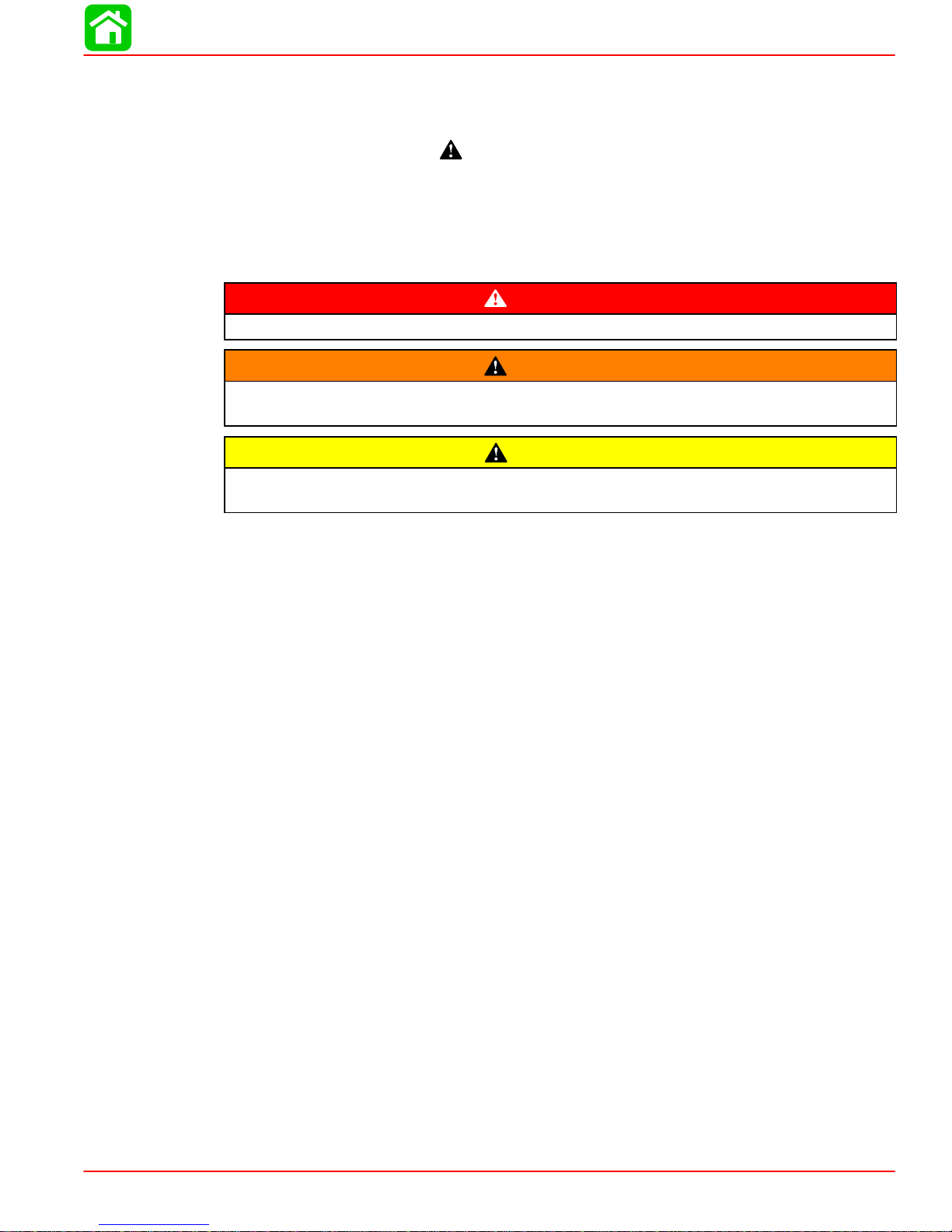
DANGER
DANGER - Immediate hazards which WILL result in severe personal injury or death.
WARNING
WARNING - Hazards or unsafe practices which COULD result in severe personal injury or death.
CAUTION
Hazards or unsafe practices which could result in minor personal injury or product
or property damage.
Notice to Users of This Manual
This service manual has been written and published by the Service Department of Mercury
Marine to aid our dealers’ mechanics and company service personnel when servicing the
products described herein.
It is assumed that these personnel are familiar with the servicing procedures of these products, or like or similar products manufactured and marketed by Mercury Marine, that they
have been trained in the recommended servicing procedures of these products which includes the use of mechanics’ common hand tools and the special Mercury Marine or recommended tools from other suppliers.
We could not possibly know of and advise the service trade of all conceivable procedures
by which a service might be performed and of the possible hazards and/or results of each
method. We have not undertaken any such wide evaluation. Therefore, anyone who uses
a service procedure and/or tool, which is not recommended by the manufacturer, first must
completely satisfy himself that neither his nor the products safety will be endangered by the
service procedure selected.
All information, illustrations and specifications contained in this manual are based on the
latest product information available at the time of publication. As required, revisions to this
manual will be sent to all dealers contracted by us to sell and/or service these products.
It should be kept in mind, while working on the product, that the electrical system and ignition
system are capable of violent and damaging short circuits or severe electrical shocks. When
performing any work where electrical terminals could possibly be grounded or touched by
the mechanic, the battery cables should be disconnected at the battery.
Any time the intake or exhaust openings are exposed during service they should be covered
to protect against accidental entrance of foreign material which could enter the cylinders and
cause extensive internal damage when the engine is started.
90-857138R1 MAY 2000 Page i
It is important to note, during any maintenance procedure replacement fasteners must have
the same measurements and strength as those removed. Numbers on the heads of the metric bolts and on the surfaces of metric nuts indicate their strength. American bolts use radial
lines for this purpose, while most American nuts do not have strength markings. Mismatched or incorrect fasteners can result in damage or malfunction, or possibly personal
injury. Therefore, fasteners removed should be saved for reuse in the same locations whenever possible. Where the fasteners are not satisfactory for re-use, care should be taken to
select a replacement that matches the original.
Cleanliness and Care of Outboard Motor
A marine power product is a combination of many machined, honed, polished and lapped
surfaces with tolerances that are measured in the ten thousands of an inch/mm. When any
product component is serviced, care and cleanliness are important. Throughout this manual, it should be understood that proper cleaning, and protection of machined surfaces and
friction areas is a part of the repair procedure. This is considered standard shop practice
even if not specifically stated.
Whenever components are removed for service, they should be retained in order. At the
time of installation, they should be installed in the same locations and with the same mating
surfaces as when removed.
Personnel should not work on or under an outboard which is suspended. Outboards should
be attached to work stands, or lowered to ground as soon as possible.
We reserve the right to make changes to this manual without prior notification.
Refer to dealer service bulletins for other pertinent information concerning the products de-
scribed in this manual.
Page Numbering
Two number groups appear at the bottom of each page. The example below is self-explanatory.
90-826883 R1 JANUARY 1998
Revision No. 1
EXAMPLE:
Page - 6A-7
Section Number
Month of Printing
Year of Printing
Page ii 90-857138R1 MAY 2000
Part of Section Letter
Page Number
SPECIFICATIONS
IMPORTANT INFORMATION
Section 1A - Specifications
Table of Contents
Specifications 1A-1. . . . . . . . . . . . . . . . . . . . . . . . . . . Propeller Information Charts 1A-8. . . . . . . . . . . . . .
Specifications
Model 4/5/6 (4-Stroke)
HORSEPOWER
(kW)
OUTBOARD
WEIGHT
FUEL
Model 4
Model 5
Model 6
Short Shaft
Long Shaft
RECOMMENDED GASOLINE Automotive Unleaded
with a Minimum Pump Posted
4 hp (2.9 kW)
5 hp (3.7 kW)
6 hp (4.4 kW)
55 lbs. (25.0 kg)
57 lbs. (26.0 kg)
Octane Rating of 87
1
A
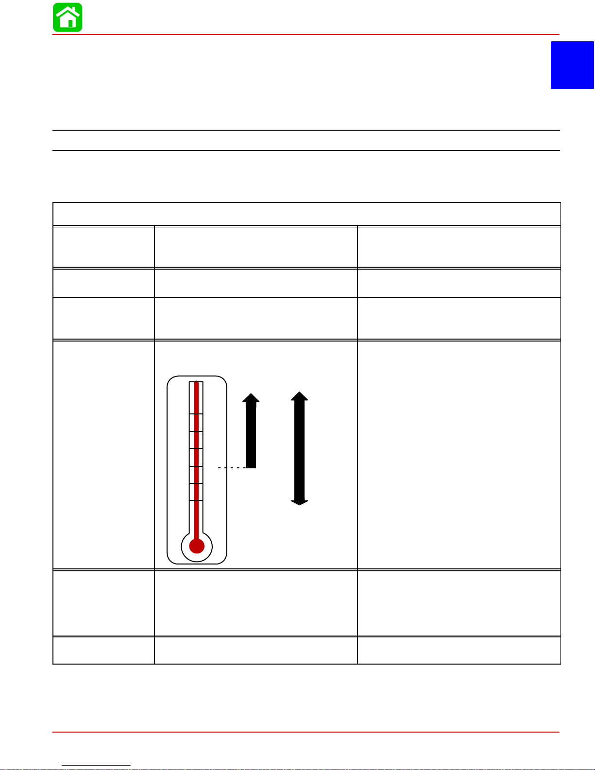
OIL
CHARGING
SYSTEM
Readings taken @
68°F (20°C).
ENGINE OIL CAPACITY
ENGINE OIL
SAE
25W-40
F°
+100
+80
+60
+40
+20
0
Alternator (Optional) Type:
Lighting Coil
Lighting Coil Resistance
Battery Charging Rectifier (Optional)
C°
+38
+27
+16
+4
–7
–18
SAE
10W-30
Either 15 fl oz. or 450 ml.
SAE 10W-30 viscosity oil is recom-
mended for use in all temperatures.
SAE 25W-40 viscosity oil may be used at
temperatures above 40° F (4° C).
Use Quicksilver 4-Cycle Marine Oil with
the proper viscosity for the expected
temperature in your area (see range
thermometer on left). If not available, use
a premium quality 4-cycle engine oil, cer-
tified to meet or exceed anyone of the
following American Petroleum Institute
(API) service classifications SH, SG, SF,
CF-4, CE, CD, CDll.
12 Volt 60 Watt
(Non Regulated Lighting Coil)
0.31 - 0.47 Ω (YEL/RED - YEL/RED)
2 Amperes (Rectified)
STARTING
SYSTEM
90-857138R1 MAY 2000 Page 1A-1
Manual Start Recoil Starter
SPECIFICATIONS
IGNITION
SYSTEM
Readings taken @
68°F (20°C).
CARBURETOR
Type
Spark Plug:
Type
Gap
Hex Size
Torque
Firing Order
Ignition Timing: (Fixed)
Capacitor Charge Coil Resistance
Trigger Coil Resistance
Ignition Coil Resistance:
Primary
Secondary (W/o Boots)
Spark Plug Boot
Engine Speed Limiter
Oil Pressure Switch (Red Light)
Idle rpm (Out Of Gear)
Idle rpm (In Forward Gear)
Wide Open Throttle rpm (WOT)
4/5 (1999 & 2000)
4/5/6 (2001 & Newer)
Pilot (Idle Mixture) Screw
4/5/6 (1999 & 2000)
European Models Only
2001 & Newer
4
5
6
All Other Models Non-Adjustable
Venturi Bore Diameter
4/5
6
Main Jet Size
4/5 (1999 & 2000)
4 (2001 & Newer)
5 (2001 & Newer)
6 (2000 & Newer)
4 (Bodensee)
5 (Bodensee)
6 (Bodensee)
Pilot Jet
4 (1999 & 2000)
5 (1999 & 2000)
4/5 (2001 & Newer)
6 (2000 & Newer)
4/5 (Bodensee)
6 (Bodensee)
Capacitor Discharge Ignition
NGK DCPR6E
0.035 in. (0.9 mm)
5/8 in. (16 mm)
13 lb-ft. (17.5 Nm)
1
25° ± 1° B.T.D.C.
95 - 134 Ω (WHT - BLK/RED)
149 - 243 Ω (RED/WHT - BLK)
0.02 - 0.38 Ω
3000 - 4400 Ω
3500 - 5200 Ω
6300 ± 200 RPM
Continuity Below 3.5 psi ± 0.7 psi
(24.5 ± 5 kPa)
1300 ± 50 rpm
1100 ± 50 rpm
4500 -5500
5000 - 6000
3 ± 1/2 Turns Out
2-1/8 ± 1/2 Turns Out
1-1/2 ± 1/2 Turns Out
2-3/4 ± 1/2 Turns Out
13.5 mm
15 mm
#70
#58
#65
#75
#55
#62
#68
#40
#42
#38
#45
#38
#42
Float Height
Page 1A-2 90-857138R1 MAY 2000
0.35 - 0.39 in. (9 - 10 mm)

SPECIFICATIONS
Fuel Pump Type
External (Plunger/Diaphragm)
Fuel Pump:
FUEL
SYSTEM
CYLINDER
BLOCK
Pressure
Plunger Stroke
Diaphragm Stroke
Fuel Tank Capacity
Type
Displacement
Number of Cylinders
2.5 - 5.0 psi (17 - 35 kPa)
0.059 in. (1.5 mm)
0.059 in. (1.5 mm)
3.2 US Gallons
4 Stroke Cycle – Over Head Valve
7.5 cu. in. (123 cc)
1
STROKE Length 1.77 in. (45 mm)
Diameter
CYLINDER
BORE
PISTON
PISTON
CLEARANCE
Standard
Oversize-0.020 in. (0.50 mm)
Taper/Out of Round Maximum
Bore Type
Piston Type
O.D. at Skirt
Standard
Oversize-0.020 in. (0.50 mm)
Piston to Cylinder Clearance
Piston Clearance Limit
2.323 in. (59.00 mm)
2.343 in. (59.50 mm)
0.003 in. (0.076 mm)
Steel
Aluminum
2.321 in. (58.960 mm)
2.341 in. (59.460 mm)
0.001 - 0.002 in.
(0.020 - 0.055 mm)
0.006 in. (0.15 mm)
RINGS
COMPRESSION
RATIO
PISTON PIN
CONNECTING
ROD
Ring End Gap (Installed)
Top
Middle
Bottom (Oil Ring)
Side Clearance:
Top
Middle
Bottom (Oil Ring)
Compression Ratio
With Decompression
4/5 (1999 & 2000)
4/5 (2001 & Newer)
6 (2000 & Newer)
Outer Diameter
Diameter of Piston Pin Hole
Clearance between Piston Pin and
Piston Pin Hole
Oil Clearance (Big End)
Side Clearance (Big End)
Small End Inside Diameter
0.006 - 0.014 in. (0.15 - 0.35 mm)
0.012 - 0.020 in. (0.30 - 0.50 mm)
0.008 - 0.016 in. (0.20 - 0.40 mm)
0.0015 - 0.003 in. (0.04 - 0.08 mm)
0.0012 - 0.003 in. (0.03 - 0.07 mm)
0.0004 - 0.007 in. (0.01 - 0.18 mm)
8.5:1
42 psi ± 14 psi (0.29 ± 0.1 MPa)
9.5:1
42 psi ± 14 psi (0.29 ± 0.1 MPa)
0.6299 in. (16.00 mm)
0.6300 in. (16.002 mm)
0.0001 - 0.0005 in.
(0.002 mm - 0.012 mm)
0.002 - 0.003 in. (0.053 - 0.079 mm)
0.008 - 0.016 in.
(0.20 - 0.40 mm)
0.6303 in. (16.01 mm)
90-857138R1 MAY 2000 Page 1A-3
SPECIFICATIONS
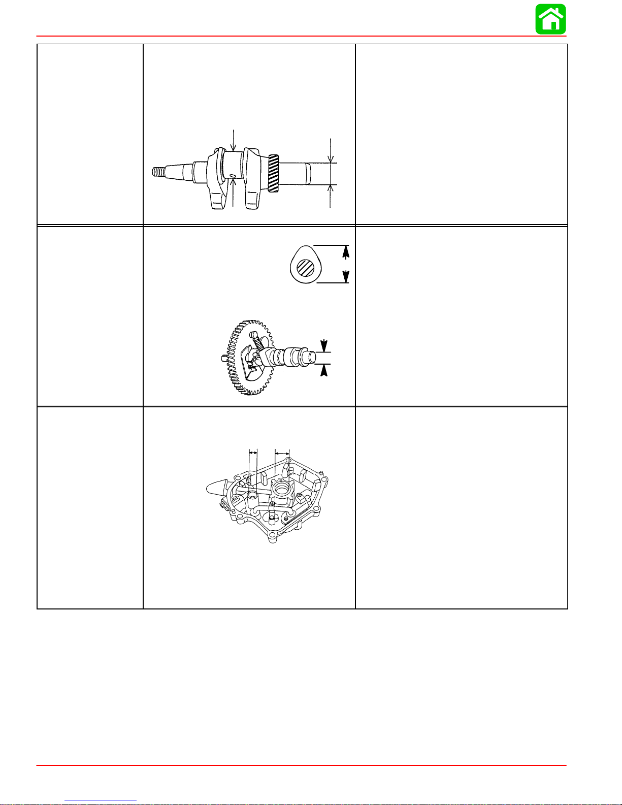
CRANKSHAFT
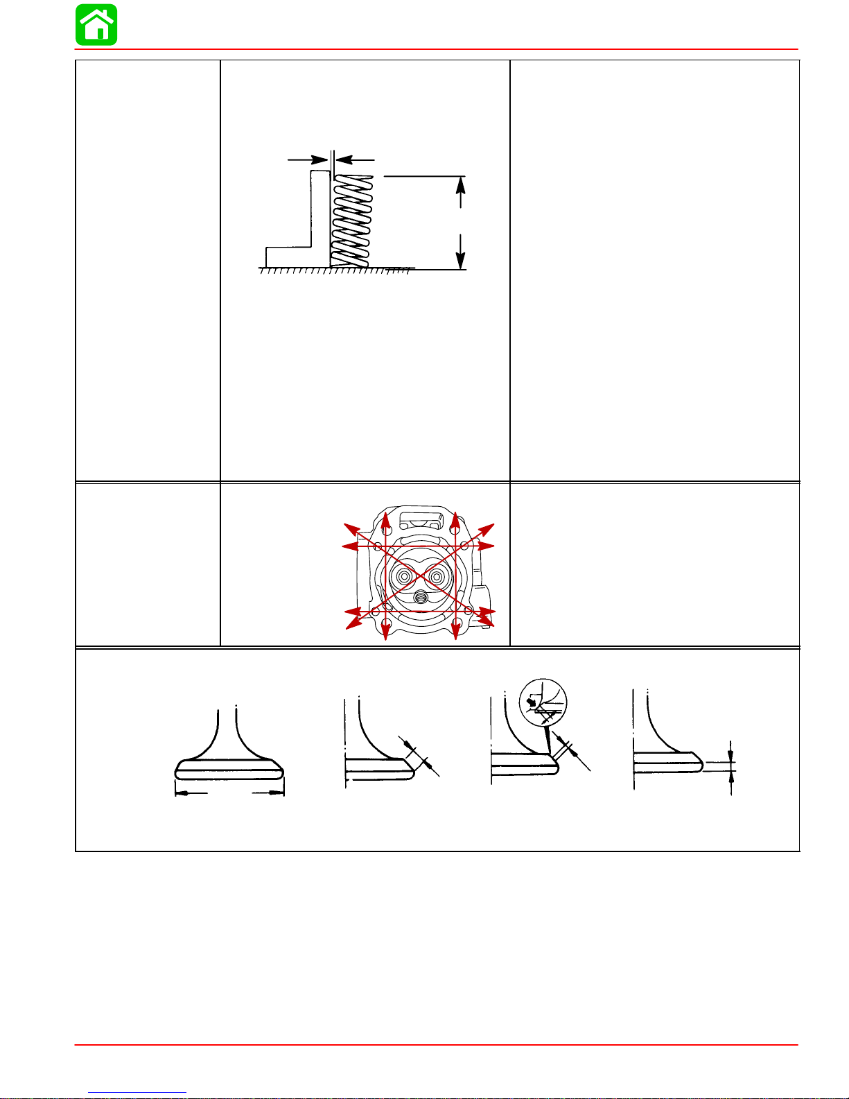
CAMSHAFT
Crankshaft Runout
Diameter of Crank Pin (A)
Outer Diameter of Crankshaft in Oil
Pan Bearing (B)
A
Camshaft Dimensions
Intake/Exhaust “A”
4 (1999 & 2000)
5 (1999 & 2000)
6 (2000)
4/5/6 (2001 & Newer)
Bearing Diameter “B”
B
B
Less than 0.002 in. (0.05 mm)
1.179 - 1.177 in.
(29.94 - 29.91 mm)
0.983 - 0.982 in.
(24.98 - 24.96 mm)
A
0.993 in. (25.24 mm)
1.047 in. (26.59 mm)
1.115 in. (28.33 mm)
1.115 in. (28.33 mm)
0.550 in. (13.98 mm)
OIL PAN
Inside Diameter of Oil Pan Bearing:
Crankshaft “A”
Camshaft “B”
B
A
Crankshaft to Oil Pan Bearing
Clearance
Camshaft to Oil Pan Bearing
Clearance
0.985 in. (25.01 mm)
0.5515 in. (14.01 mm)
0.0006 - 0.0015 in. (0.015 - 0.040 mm)
0.0008 - 0.002 in. (0.02 - 0.05 mm)
Page 1A-4 90-857138R1 MAY 2000
VALVE SPRING
Free Length (Intake/Exhaust) “a”
Tilt Limit “b” (Intake/Exhaust)
4/5 (1999)
4/5/6 (2000 & Newer)
b
a
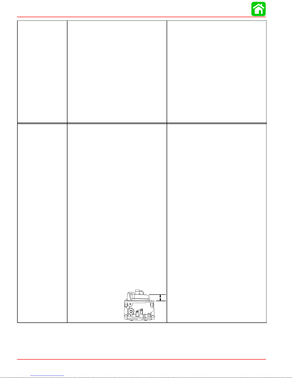
Compressed Pressure (Installed)
Intake/Exhaust:
Closed Height 0.965 in. (24.4 mm)
4/5 (1999 & 2000)
6 (2000)
4/5/6 (2001 & Newer)
Open Height 0.709 in. (17.4 mm)
4/5 (1999 & 2000)
6 (2000)
4/5/6 (2001 & Newer)
Direction of Winding (Intake/Exhaust)
SPECIFICATIONS
a = 1.260 in. (32.0 mm)
b = 0.044 in. (1.12 mm)
a = 1.378 in. (35.0 mm)
b = 0.044 in. (1.12 mm)
17 lbf. (7.7 kgf)
24 lbf. (10.8 kgf)
24 lbf. (10.8 kgf)
31 lbf. (14.0 kgf)
39.4 lbf. (17.9 kgf)
39.4 lbf. (17.9 kgf)
Right Hand
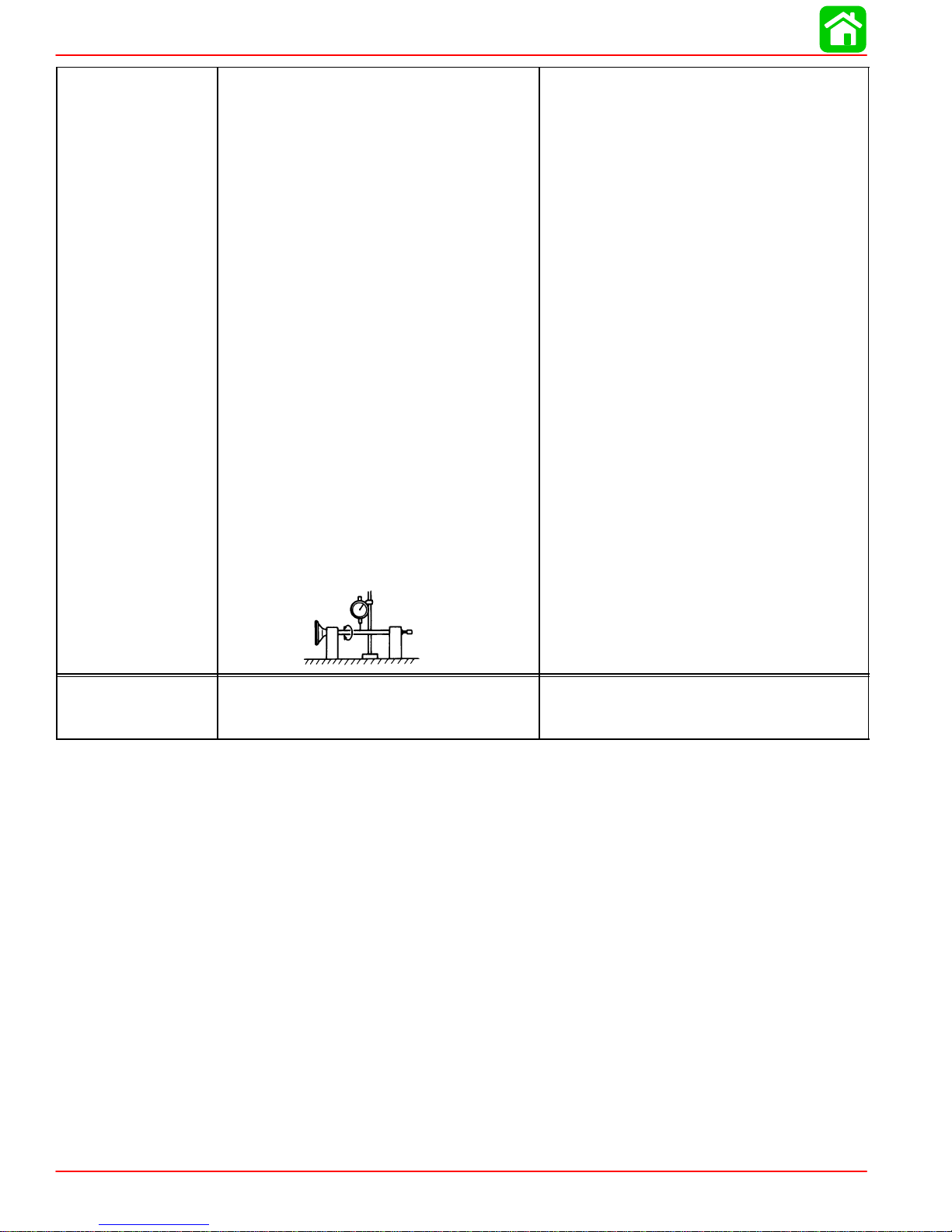
CYLINDER HEAD
Head Diameter Face Width
Warp Limit *
* Lines indicate
straight edge
measurement
“A”
Valve Dimensions
“B”
Seat Width
0.0012 in. (0.03 mm)
“C”
“D”
Margin Thickness
90-857138R1 MAY 2000 Page 1A-5
SPECIFICATIONS
VALVES
Valve/Valve Seat/Valve Guides:
Valve Clearance (cold)
Intake
Exhaust
Valve Dimensions:
“A” Head Diameter
Intake
Exhaust
“B” Face Width
Intake
Exhaust
“C” Seat Width
Intake
Exhaust
“D” Margin Thickness
Intake
Exhaust
Stem Outside Diameter
Intake
Exhaust
Guide Inside Diameter
Intake
Exhaust
Stem To Guide Clearance
Intake
Exhaust
Stem Run-out Limit (max.)
0.002 - 0.005 in. (0.06 - 0.14 mm)
0.004 - 0.007 in. (0.11 - 0.19 mm)
0.980 - 0.988 in. (24.9 - 25.1 mm)
0.941 - 0.949 in. (23.9 - 24.1 mm)
0.102 in. (2.6 mm)
0.102 in. (2.6 mm)
0.031 in. (0.8 mm)
0.031 in. (0.8 mm)
0.028 in. (0.7 mm)
0.047 in. (1.2 mm)
0.216 in. (5.48 mm)
0.214 in. (5.44 mm)
0.2165 in. (5.5 mm)
0.2165 in. (5.5 mm)
0.0008 - 0.0017 in. (0.020 - 0.044 mm)
0.0018 - 0.0028 in. (0.045 - 0.072 mm)
0.0006 in. (0.016 mm)
THERMOSTAT
Valve Opening Temperature
Full Open Temperature
Valve Lift (Minimum)
122°F - 129°F (50°C - 54°C)
145°F - 153°F (63°C - 67°C)
0.12 in. (3 mm)
Page 1A-6 90-857138R1 MAY 2000
SPECIFICATIONS
LUBRICATION
SYSTEM
Pump Type
Engine Oil Pressure* (Warm Engine):
@ 1300 rpm
@ 5000 rpm
Engine Oil Pan Capacity
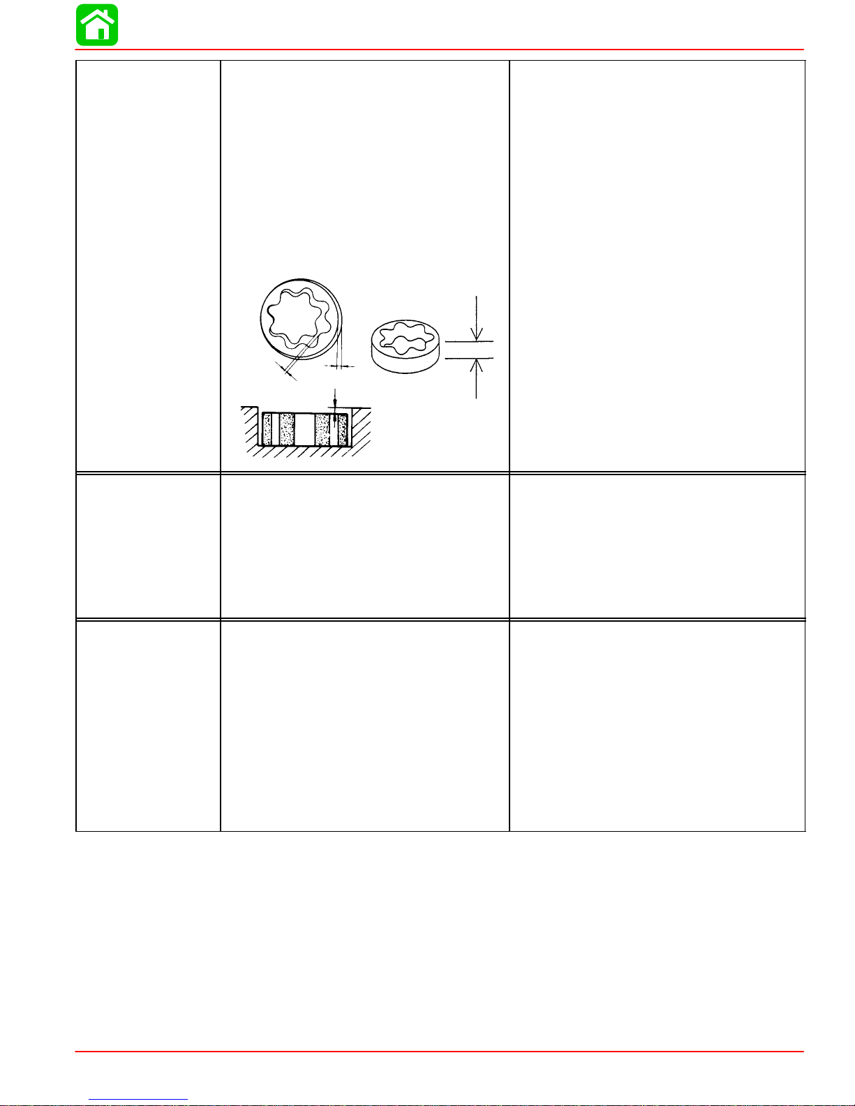
Oil Pump Clearance:
Inner Rotor to Outer Rotor “A”
Outer Rotor to Body “B”
Rotor to Body (Side) “C”
Height of Outer Rotor “D”
Relief Valve Operating Pressure*
D
A
B
C
Trochoid
4.0 psi (0.03 MPa) Minimum
21.0 psi (0.15 MPa) Minimum
0.95 pt (450 ml)
0.006 in. (0.15 mm) or Less
0.005 - 0.008 in. (0.12 - 0.20 mm)
0.0008 - 0.0028 in. (0.02 - 0.07 mm)
0.236 in. (5.99 mm)
31 - 40 psi (2.2 - 2.8 kg/cm
2
)
216 - 275 kPa
Transom Height - Short Shaft
- Long Shaft
Steering Pivot Range
MID-SECTION
Tilt Pin Positions
Total Tilt Angle
Tilt Angle
Shallow Water Tilt Angle
Allowable Transom Thickness
Gear Ratio
Gearcase Capacity
Lubricant Type
Quicksilver Gear Lube-Premium Blend
Forward Gear
Number of Teeth
GEAR HOUSING
(2.15:1)
Pinion Gear
Number of Teeth
Pinion Height
Forward Gear Backlash
Water Pressure:
@ 1300 rpm (Idle) Neutral
@ 5000 rpm
* Oil pressure specifications listed were obtained with oil at 165°F (75°C)
Water pressure readings will vary with thermostat operation.
17 in. (38 cm)
22 in. (51 cm)
78°
6
75°
4° - 24°
32.5°
2.2 in. (55 mm)
2.15:1
6.5 fl oz (195 mL)
28 Spiral/Bevel
13 Spiral/Bevel
Floating
No Adjustment
2.3 - 3.6 psi (16 - 25 kPa)
8 - 15 psi (55 - 103.5 kPa)
90-857138R1 MAY 2000 Page 1A-7

SPECIFICATIONS
Propeller Information Charts
Mercury/Mariner 4 (4-Stroke)
Wide Open Throttle RPM : 5000-6000
Recommended Transom Heights : 15”, 20”
Right Hand Rotation Standard
Gear Reduction : 2.15:1
Approx.
No. of
Diameter
8-3/8” 9” 3 Alum Up to 400 Up to 14’ 12-18 48-812950T1
8-3/8” 8” 3 Alum 300-500 13-15’ 10-16 48-812950
8-3/8” 7” 3 Alum 400-700 14-16’ 8-13 48-812949*
8-3/8” 6” 3 Alum 600+ 15’+ 1-11 48-16144
8-3/8” 6” 3 Alum Sailboat 1-8 48-812951A1
Pitch
Blades
Material
Gross Boat
Wgt. (lbs)
Approx.
Boat
Length
Speed
Range
(mph)
Part Number
Mercury/Mariner 5 (4-Stroke)
Wide Open Throttle RPM : 5000-6000
Recommended Transom Heights : 15”, 20”
Right Hand Rotation Standard
Gear Reduction : 2.15:1
Approx.
No. of
Diameter
8-3/8” 9” 3 Alum Up to 500 Up to 14’ 12-18 48-812950T1
8-3/8” 8” 3 Alum 400-700 13-15’ 10-16 48-812950*
Pitch
Blades
Material
Gross Boat
Wgt. (lbs)
Approx.
Boat
Length
Speed
Range
(mph)
Part Number
Propeller
Propeller
8-3/8” 7” 3 Alum 500-900 14-16’ 8-13 48-812949
8-3/8” 6” 3 Alum 600+ 15’+ 1-11 48-16144
8-3/8” 6” 3 Alum Sailboat 1-8 48-812951A1
Mercury/Mariner 6 (4-Stroke)
Wide Open Throttle RPM : 5000-6000
Recommended Transom Heights : 15”, 20”
Right Hand Rotation Standard
Gear Reduction : 2.15:1
Approx.
No. of
Diameter
8-3/8” 9” 3 Alum Up to 500 Up to 14’ 14-21 48-812950T1
8-3/8” 8” 3 Alum 500-800 13-15’ 12-18 48-812950*
8-3/8” 7” 3 Alum 600-1100 14-16’ 10-14 48-812949
8-3/8” 6” 3 Alum 800+ 15’+ 1-12 48-16144
8-3/8” 6” 3 Alum Sailboat 1-9 48-812951A1
*Standard propeller shipped with outboard.
Pitch
Blades
Material
Gross Boat
Wgt. (lbs)
Approx.
Boat
Length
Speed
Range
(mph)
Part Number
Propeller
Page 1A-8 90-857138R1 MAY 2000
MAINTENANCE
IMPORTANT INFORMATION
Section 1B - Maintenance
Table of Contents
Table of Contents 1B-1. . . . . . . . . . . . . . . . . . . . . . . . . . . . .
Specifications 1B-1. . . . . . . . . . . . . . . . . . . . . . . . . . . . . . . . .
Gear Case Lubricant Capacity 1B-1. . . . . . . . . . . . . . .
Special Tools 1B-1. . . . . . . . . . . . . . . . . . . . . . . . . . . . . .
Quicksilver Lubricant/Sealant 1B-2. . . . . . . . . . . . . . . .
Inspection and Maintenance Schedule 1B-3. . . . . . . . . . .
Before Each Use 1B-3. . . . . . . . . . . . . . . . . . . . . . . . . . .
After Each Use 1B-3. . . . . . . . . . . . . . . . . . . . . . . . . . . . .
Every 100 Hours of Use or Once Yearly,
Whichever Occurs First 1B-3. . . . . . . . . . . . . . . . . . . . .
Flushing The Cooling System 1B-4. . . . . . . . . . . . . . . . . . .
Fuel System 1B-4. . . . . . . . . . . . . . . . . . . . . . . . . . . . . . . . . .
Fuel Line Inspection 1B-4. . . . . . . . . . . . . . . . . . . . . . . .
Engine Fuel Filter 1B-4. . . . . . . . . . . . . . . . . . . . . . . . . .
Corrosion Control Anode 1B-5. . . . . . . . . . . . . . . . . . . . . . .
Spark Plug Inspection 1B-5. . . . . . . . . . . . . . . . . . . . . . . . . .
1
B
Lubrication Points 1B-6. . . . . . . . . . . . . . . . . . . . . . . . . . . . .
Changing Engine Oil 1B-8. . . . . . . . . . . . . . . . . . . . . . . . . . .
Engine Oil Capacity 1B-8. . . . . . . . . . . . . . . . . . . . . . . . .
Oil Changing Procedure 1B-8. . . . . . . . . . . . . . . . . . . . .
Oil Filling 1B-8. . . . . . . . . . . . . . . . . . . . . . . . . . . . . . . . . .
Gear Case Lubrication 1B-9. . . . . . . . . . . . . . . . . . . . . . . . .
Gear Case Lubricant Capacity 1B-9. . . . . . . . . . . . . . .
Draining Gear Case 1B-9. . . . . . . . . . . . . . . . . . . . . . . .
Checking Lubricant Level and Refilling
Gear Case 1B-10. . . . . . . . . . . . . . . . . . . . . . . . . . . . . . .
Storage Preparations 1B-10. . . . . . . . . . . . . . . . . . . . . . . . .
Fuel System 1B-10. . . . . . . . . . . . . . . . . . . . . . . . . . . . . .
Protecting External Engine Components 1B-10. . . . .
Protecting Internal Engine Components 1B-11. . . . . .
Gear Case 1B-11. . . . . . . . . . . . . . . . . . . . . . . . . . . . . . .
Positioning Outboard for Storage 1B-11. . . . . . . . . . . .
Specifications
Gear Case Lubricant Capacity
Gear Case Ratio Capacity
2.15:1 6.6 fl oz. (195.0 ml)
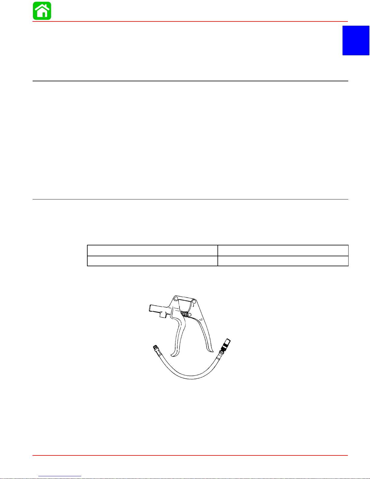
Special Tools
1. Grease Gun 91-37299A1
90-857138R1 MAY 2000 Page 1B-1
MAINTENANCE
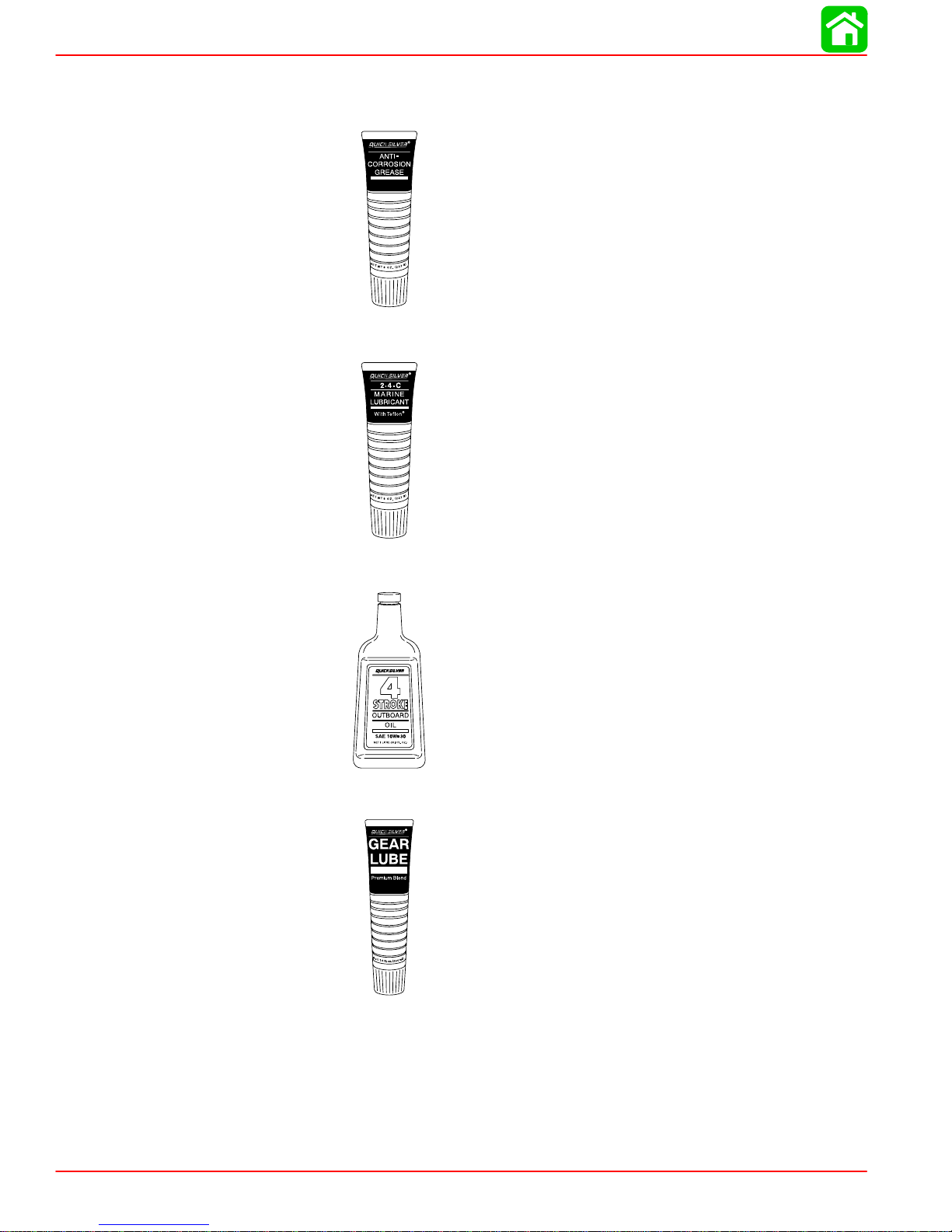
Quicksilver Lubricant/Sealant
1. Quicksilver Anti-Corrosion Grease P/N 92-850735A1
2. 2-4-C Marine Lubricant with Teflon P/N 92-850736A1
3. SAE 10-30W Motor Oil P/N 92-802833A1
4. Quicksilver Gear Lubricant P/N 92-19007A24
Page 1B-2 90-857138R1 MAY 2000

Inspection and Maintenance Schedule
Before Each Use
1. Check engine oil level.
2. Visually inspect the fuel system for deterioration or leaks.
3. Check outboard for tightness on transom.
4. Check propeller blades for damage.
After Each Use
1. Flush out the outboard cooling system if operating in salt or polluted water.
2. Wash off all salt deposits and flush out the exhaust outlet of the propeller and gear case
with fresh water if operating in salt water.
Every 100 Hours of Use or Once Yearly, Whichever Occurs First
1. Lubricate all lubrication points. Lubricate more frequently when used in salt water.
2. Change engine oil. The oil should be changed more often when the engine is operated
under adverse conditions such as extended trolling.
MAINTENANCE
3. Inspect and clean spark plugs.
4. Check fuel line filter for contaminants.
5. Check corrosion control anode. Check more frequently when used in salt water.
6. Drain and replace gear case lubricant.
7. Lubricate splines on the drive shaft.
8. Check tightness of bolts, nuts, and other fasteners.
9. Replace water pump impeller.
These items should be serviced by an authorized dealer.
∗
∗
∗
90-857138R1 MAY 2000 Page 1B-3
MAINTENANCE
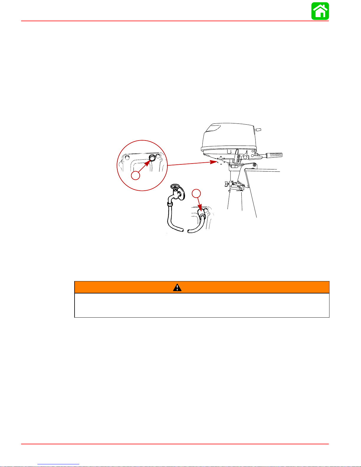
Flushing The Cooling System
Flush the internal water passages of the outboard with fresh water after each use in salt,
polluted, or muddy water. This will help prevent a buildup of deposits from clogging the internal water passages.
NOTE: Do not run the engine while flushing the cooling system.
1. Remove plug and gasket and thread-in hose coupling.
2. Attach a wate r hose to the hose coupling. T urn on the water gently and flush the cooling
system for 3 to 5 minutes.
3. Remove the thread-in hose coupling and reinstall plug and gasket.
a
Fuel System
Avoid serious injury or death from gasoline fire or explosion. Carefully follow all
fuel system service instructions. Always stop the engine and DO NOT smoke or allow open flames or sparks in the area while servicing any part of the fuel system.
Before servicing any part of the fuel system, stop engine and disconnect the battery . Drain
the fuel system completely. Use an approved container to collect and store fuel. Wipe up
any spillage immediately. Material used to contain spillage must be disposed of in an approved receptacle. Any fuel system service must be performed in a well ventilated area. Inspect any completed service work for sign of fuel leakage.
b
a- Plug and Gasket
b- Hose Coupling
WARNING
Fuel Line Inspection
Visually inspect the fuel line and primer bulb for cracks, swelling, leaks, hardness or other
signs of deterioration or damage. If any of these conditions is found, the fuel line or primer
bulb must be replaced.
Engine Fuel Filter
Inspect the fuel line filter. If the filter appears to be contaminated, remove and replace.
Page 1B-4 90-857138R1 MAY 2000
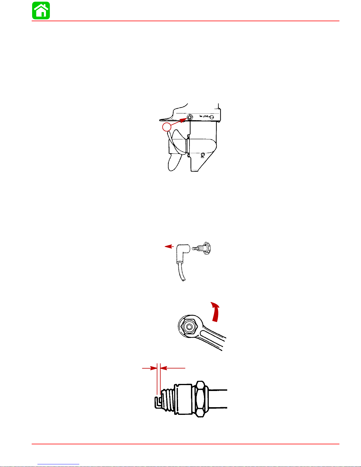
Corrosion Control Anode
Your outboard has a corrosion control anode installed to the gear case. An anode helps protect the outboard against galvanic corrosion by sacrificing its metal to be slowly eroded instead of the outboard metals.
The anode requires periodic inspection especially in salt water which will accelerate the erosion. To m a i ntain this corr o s i o n p r o t e c t i o n , a l ways replace the anode before it is completely
eroded. Never paint or apply a protective coating on the anode as this will reduce effectiveness of the anode.
a- Anode
MAINTENANCE
a
Spark Plug Inspection
Inspect spark plugs at the recommended intervals.
1. Remove the spark plug leads by twisting the rubber boots slightly and pull off.
2. Remove the spark plugs to inspect and clean. Replace spark plug if electrode is worn
or the insulator is rough, cracked, broken, blistered or fouled.
3. Set the spark plug gap. See Specification Chart in General Information Section.
4. Before reinstalling spark plugs, clean away dirt on the spark plug seats. Install plugs fin-
ger tight, and tighten 1/4 turn or torque to 13 lb-ft (17.5 Nm).
90-857138R1 MAY 2000 Page 1B-5
MAINTENANCE
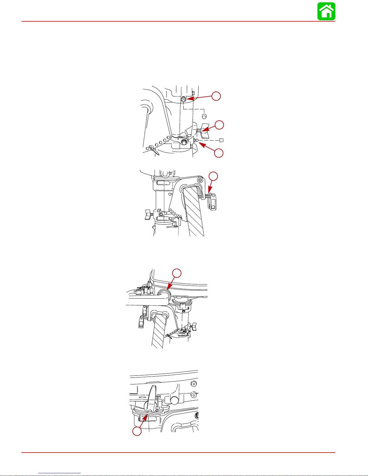
Lubrication Points
Lubricate Points 1 thru 5 with Quicksilver 2-4-C with Teflon Marine Lubricant or Special Lubricant 101.
1. Co-Pilot – Lubricate threads.
2. Swivel Bracket – Lubricate fitting.
3. Transom Clamp Screws – Lubricate threads.
2
1
2
3
NOTE: Lubricating points 4 and 5 require disassembly of the product. These points should
be lubricated at least once a year by an authorized dealer.
4. Tiller Handle Rubber Bushing – Lubricate internal diameter.
4
5. Shift Handle Detent – Lubricate detent.
Page 1B-6 90-857138R1 MAY 2000
5
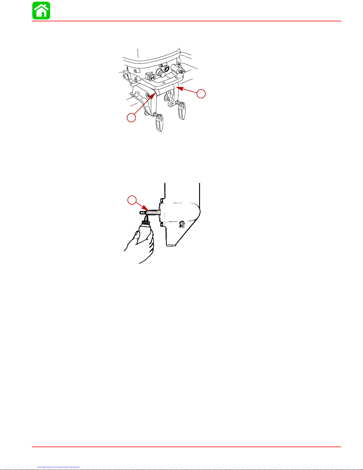
MAINTENANCE
Lubricate Point 6 with Light Weight Oil
6. Tilt Pivot.
6
6
Lubricate Point 7 with Quicksilver Anti-Corrosion Grease or 2-4 - C with Teflon Marine
Lubricant.
7. Propeller Shaft – Refer to Propeller Replacement for removal and installation of the pro-
peller. Coat the entire propeller shaft with lubricant to prevent the propeller hub from corroding to the shaft.
7
90-857138R1 MAY 2000 Page 1B-7
MAINTENANCE
Changing Engine Oil
ENGINE OIL CAPACITY
15 fl oz. (450 mL)
OIL CHANGING PROCEDURE
1. Place outboard in an upright slightly tilted position.
2. Turn the steering on the outboard to gain access to the drain plug. Remove drain plug
and drain engine oil into an appropriate container. Lubricate the seal on the drain plug
with oil and reinstall.
a
OIL FILLING
a- Drain Plug
IMPORT ANT: Inspect oil for signs of contamination. Oil contaminated with water will
have a milky color to it; oil contaminated with fuel will smell strongly of fuel. If contaminated oil is noticed, have the engine checked by your dealer.
IMPORTANT: Do not overfill. Be sure that the outboard is upright (not tilted) when
checking oil.
Remove the oil fill cap and refill with 15 fl oz. (450 mL) of oil. Reinstall the oil fill cap.
Idle engine for five minutes and check for leaks. Stop engine and check oil level on dipstick.
Add oil if necessary.
Page 1B-8 90-857138R1 MAY 2000
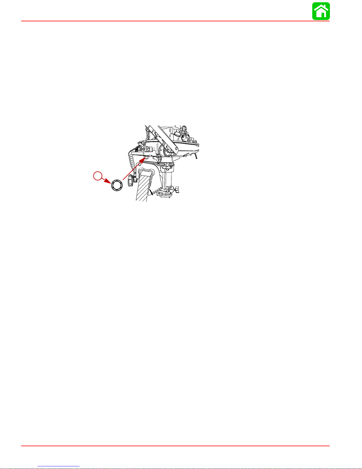
Gear Case Lubrication
Gear Case Lubricant Capacity
Gear Case Ratio Capacity
2.15:1 6.6 fl oz. (195 mL)
When adding or changing gear case lubricant, visually check for the presence of water in
the lubricant. If water is present, it may have settled to the bottom and will drain out prior
to the lubricant, or it may be mixed with the lubricant, giving it a milky colored appearance.
If water is noticed, have the gear case checked by your dealer. Water in the lubricant may
result in premature bearing failure or, in freezing temperatures, will turn to ice and damage
the gear case.
Also examine the gear case lubricant for metal particles. A small amount of metal filings or
fine metal particles indicates normal gear wear. An excessive amount of metal filings or
larger particles (chips) may indicate abnormal gear wear and should be checked by an
authorized dealer.
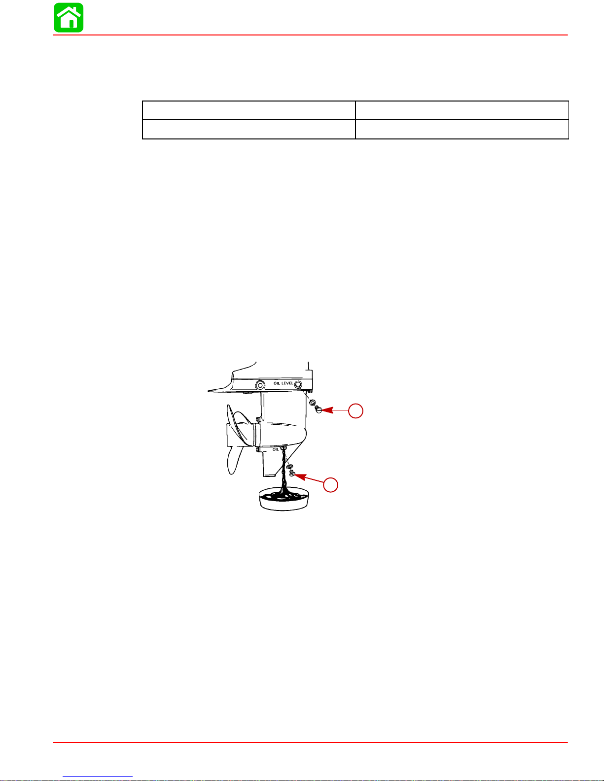
Draining Gear Case
1. Place outboard in a vertical operating position.
MAINTENANCE
2. Place drain pan below outboard.
3. Remove fill/drain plug and vent plug and drain lubricant.
b
a
a- Fill/Drain Plug
b- Vent Plug
90-857138R1 MAY 2000 Page 1B-9
MAINTENANCE
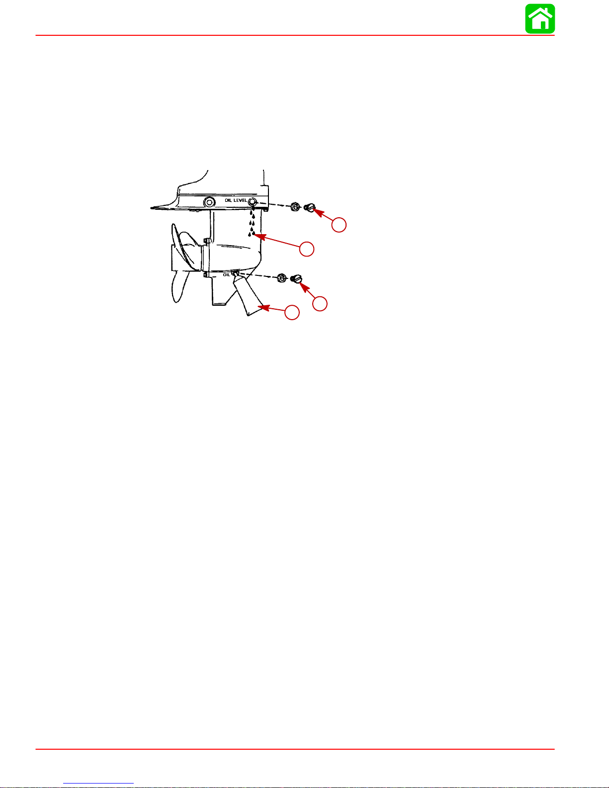
Checking Lubricant Level and Refilling Gear case
1. Place outboard in a vertical operating position.
2. Remove vent plug.
3. Place lubricant tube into the fill hole and add lubricant until it appears at the vent hole.
4. Stop adding lubricant. Install the vent plug and sealing washer before removing the lubricant tube.
5. Remove lubricant tube and reinstall cleaned fill/drain plug and sealing washer.
a
c
d
b
a- Vent Plug/Sealing Washer
b- Lubricant Tube
c- Vent Hole
d- Fill/Drain Plug and Sealing Washer
Storage Preparations
Fuel System
IMPORTANT: Gasoline containing alcohol (ethanol or methanol) can cause a formation of acid during storage and can damage the fuel system. If the gasoline being
used contains alcohol, it is advisable to drain as much of the remaining gasoline as
possible from the fuel tank, remote fuel line, and engine fuel system.
Fill the fuel system (tank, hoses, fuel pumps, and fuel injection systems) with treated (stabilized) fuel to help prevent formation of varnish and gum. Proceed with following instructions.
1. Portable Fuel Tank – Pour the required amount of Quicksilver Gasoline Stabilizer (follow
instructions on container) into fuel tank. T ip fuel tank back and forth to mix stabilizer with
the fuel.
2. Permanently Installed Fuel Tank – Pour the required amount of Quicksilver Gasoline
Stabilizer (follow instructions on container) into a separate container and mix with approximately one quart (one liter) of gasoline. Pour this mixture into fuel tank.
3. Place the outboard in water or connect flushing attachment for circulating cooling water .
Run the engine for ten minutes to allow treated fuel to fill the fuel system.
Protecting External Engine Components
1. Lubricate all outboard components listed in the Inspection and Maintenance Schedule.
2. Touch up any paint nicks.
3. Spray Quicksilver Corrosion Guard on external metal surfaces (except corrosion control
anodes).
Page 1B-10 90-857138R1 MAY 2000
Protecting Internal Engine Components
NOTE: Before performing Steps 1 and 2, make sure the fuel system has been prepared for
storage.
1. Change the engine oil.
2. Place the outboard in water or connect flushing attachment for circulating cooling water .
Start the engine and let it run in neutral to warm up.
3. With engine running at fast idle, stop the fuel flow by disconnecting the remote fuel line.
When engine begins to stall, quickly spray Quicksilver Storage Seal into carburetor until
engine stops from lack of fuel.
4. Remove the spark plugs and inject a five second spray of Quicksilver Storage Seal
around the inside of each cylinder.
5. Rotate the flywheel manually several times to distribute the storage seal in the cylinders.
Reinstall spark plugs.
Gear Case
Drain and refill the gear case lubricant (refer to maintenance procedure).
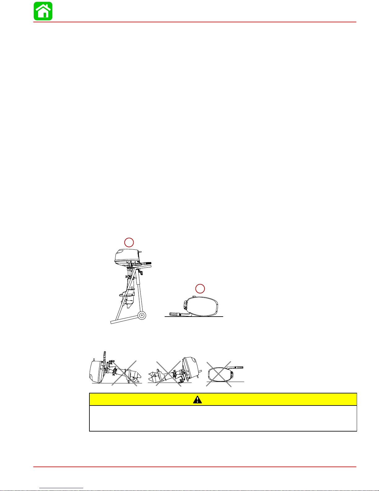
Positioning Outboard for Storage
1. Carry, transport or store the outboard only in these two positions. These positions will
prevent oil from draining out of the crankcase.
MAINTENANCE
a. Upright
b. Tiller Side Down
a
b
2. Never carry, store or transport the outboard in these positions. Engine damage could
result from oil draining out of the crankcase.
If outboard is on a boat and is stored tilted up in freezing temperature, trapped cooling water or rain water that may have entered the propeller exhaust outlet in the gear
case could freeze and cause damage to the outboard.
90-857138R1 MAY 2000 Page 1B-11
CAUTION

GENERAL INFORMATION
IMPORTANT INFORMATION
Section 1C - GENERAL INFORMATION
Table of Contents
Serial Number Location 1C-2. . . . . . . . . . . . . . . . . . . . . . . .
Conditions Affecting Performance 1C-2. . . . . . . . . . . . . . .
Weather 1C-2. . . . . . . . . . . . . . . . . . . . . . . . . . . . . . . . . . .
Boat 1C-3. . . . . . . . . . . . . . . . . . . . . . . . . . . . . . . . . . . . . .
Engine 1C-5. . . . . . . . . . . . . . . . . . . . . . . . . . . . . . . . . . . .
Following Complete Submersion 1C-6. . . . . . . . . . . . . . . .
Submerged While Running 1C-6. . . . . . . . . . . . . . . . . .
Salt Water Submersion 1C-6. . . . . . . . . . . . . . . . . . . . . .
Fresh Water Submersion 1C-6. . . . . . . . . . . . . . . . . . . .
1
C
Propeller Selection 1C-7. . . . . . . . . . . . . . . . . . . . . . . . . . . .
Propeller Removal/Installation 1C-8. . . . . . . . . . . . . . . . . .
Compression Check 1C-10. . . . . . . . . . . . . . . . . . . . . . . . . .
Cylinder Leakage Testing 1C-11. . . . . . . . . . . . . . . . . . . . . .
Analysis 1C-11. . . . . . . . . . . . . . . . . . . . . . . . . . . . . . . . . .
Painting Procedures 1C-12. . . . . . . . . . . . . . . . . . . . . . . . . .
Cleaning & Painting Aluminum Propellers &
Gear Housings 1C-12. . . . . . . . . . . . . . . . . . . . . . . . . . . .
Decal Application 1C-13. . . . . . . . . . . . . . . . . . . . . . . . . . . . .
Decal Removal 1C-13. . . . . . . . . . . . . . . . . . . . . . . . . . . .
Instructions for “Wet” Application 1C-13. . . . . . . . . . . .
90-857138R1 MAY 2000 Page 1C-1
GENERAL INFORMATION
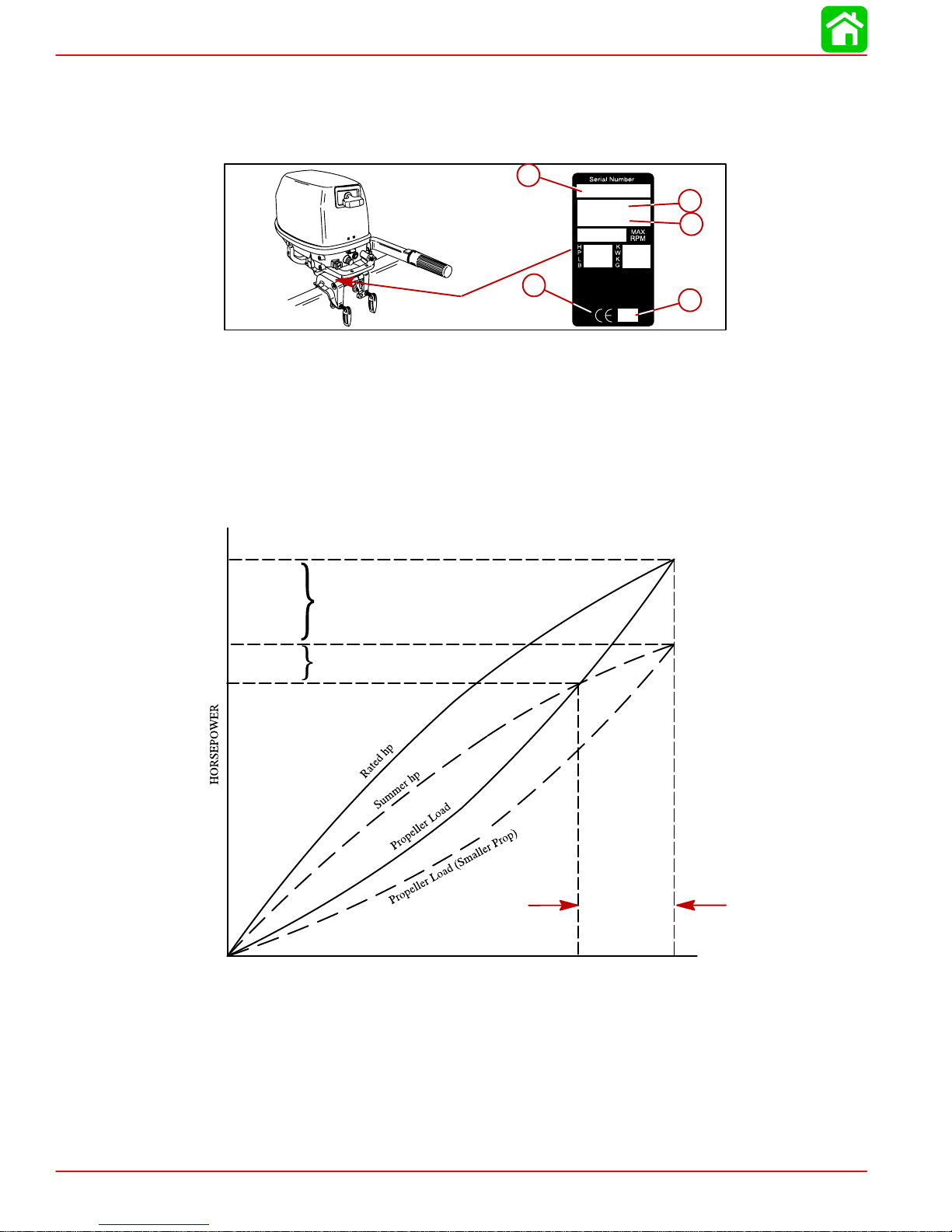
Serial Number Location
The Outboard serial number is located on the lower starboard side of the engine block. A
serial number is also located on the top side of the swivel bracket.
a-Serial Number
b-Model Year
c-Model Description
d-Year Manufactured
e-Certified Europe Insignia
Conditions Affecting Performance
Weather
a
a
e
e
OGXXXXXX
19XX
XXXX
XX
b
b
c
c
d
d
Rated hp
Horsepower Loss
Due to Atmosphere
Summer hp
Conditions
Secondary Loss Due to
Propeller Becoming To
Large for Summer
Horsepower
ENGINE RPM
RPM Drop Due
to Weather
Rated RPM
It is a known fact that weather conditions exert a profound effect on power output of internal
combustion engines. Therefore, established horsepower ratings refer to the power that the
engine will produce at its rated rpm under a specific combination of weather conditions.
Corporations internationally have settled on adoption of I.S.O. (International Standards Organization) engine test standards, as set forth in I.S.O. 3046 standardizing the computation
of horsepower from data obtained on the dynamometer, correcting all values to the power
that the engine will produce at sea level, at 30% relative humidity at 77° F (25°C) temperature and a barometric pressure of 29.61 inches of mercury.
Page 1C-2 90-857138R1 MAY 2000

GENERAL INFORMATION
Summer Conditions of high temperature, low barometric pressure and high humidity all
combine to reduce the engine power. This, in turn, is reflected in decreased boat speeds--as
much as 2 or 3 miles-per-hour (3 or 5 Km per-hour) in some cases. (Refer to previous chart.)
Nothing will regain this speed for the boater, but the coming of cool, dry weather.
In pointing out the practical consequences of weather effects, an engine--running on a hot,
humid summer day--may encounter a loss of as much as 14% of the horsepower it would
produce on a d r y, bris k spring or fall day. The horsepower, that any internal combustion engine produces, depends upon the density of the air that it consumes and, in turn, this density
is dependent upon the temperature of the air, its barometric pressure and water vapor (or
humidity) content.
Accompanying this weather-inspired loss of power is a second but more subtle loss. At rigging time in early spring, the engine was equipped with a propeller that allowed the engine
to turn within its recommended rpm range at full throttle. With the coming of the summer
weather and the consequent drop in available horsepower, this propeller will, in ef fect, become too large. Consequently, the engine operates at less than its recommended rpm.
Due to the horsepower/rpm characteristics of an engine, this will result in further loss of
horsepower at the propeller with another decrease in boat speed. This secondary loss, however, can be regained by switching to a smaller pitch propeller that allows the engine to again
run at recommended rpm.
For boaters to realize optimum engine performance under changing weather conditions, it
is essential that the engine have the proper propeller to allow it to operate at or near the top
end of the recommended maximum rpm range at wide-open-throttle with a normal boat
load.
Not only does this allow the engine to develop full power, but equally important is the fact
that the engine also will be operating in an rpm range that discourages damaging detonation. This, of course, enhances overall reliability and durability of the engine.
Boat
WEIGHT DISTRIBUTION
1. Proper positioning of the weight inside the boat (persons and gear) has a significant ef-
fect on the boat’s performance, for example:
a. Shifting weight to the rear (stern).
b. Shifting weight to the front (bow).
c. Adjusting tilt pin to achieve best performance and handling.
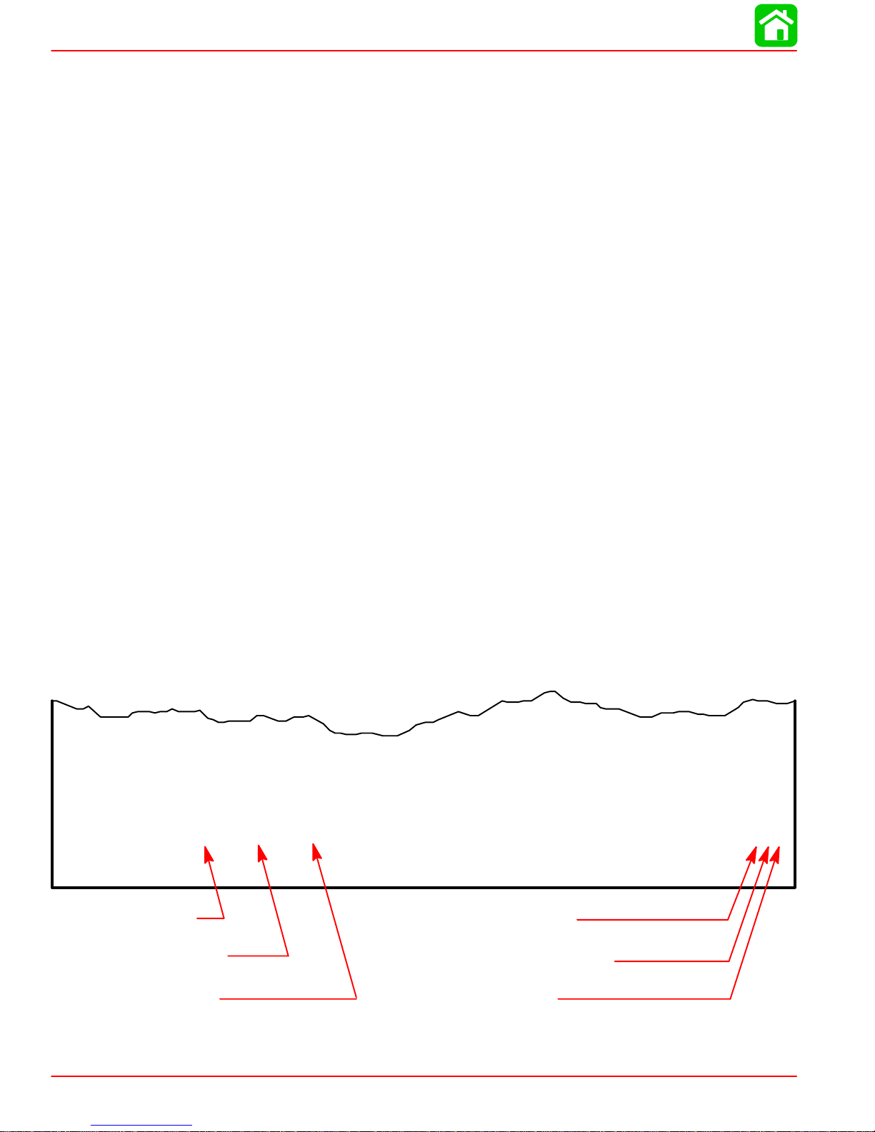
BOTTOM
For maximum speed, a boat bottom should be nearly a flat plane where it contacts the water
and particularly straight and smooth in fore-and-aft direction.
(1.)Generally increases top speed.
(2.)If in excess, can cause the boat to porpoise.
(3.)Can make the bow bounce excessively in choppy water.
(4.)Will increase the danger of the following - wave splashing into the boat when
coming off plane.
(1.)Improves ease of planing off.
(2.)Generally improves rough water ride.
(3.)If excessive, can make the boat veer left and right (bow steer).
90-857138R1 MAY 2000 Page 1C-3

GENERAL INFORMATION
1. Hook: Exists when bottom is concave in fore-and-aft direction when viewed from the
2. Rocker: The reverse of hook and much less common. “Rocker” exists if bottom is con-
3. Surface Roughness: Moss, barnacles, etc., on boat or corrosion of outboard’s gear
WATER ABSORPTION
It is imperative that all through hull fasteners be coated with a quality marine sealer at time
of installation. Water intrusion into the transom core and/or inner hull will result in additional
boat weight (reduced boat performance), hull decay and eventual structural failure.
CAVITATION
Cavitation is caused by water vapor bubbles forming either from a sharp edge or angle on
the gear case, from an irregularity in the propeller blade itself or from improper engine installation (too high). These vapor bubbles flow back and collapse when striking the surface of
the propeller blade resulting in the erosion of the propeller blade surface. If allowed to continue, eventual blade failure (breakage) will occur.
side. When boat is planing, “hook” causes more lift on bottom near transom and allows
bow to drop, thus greatly increasing wetted surface and reducing boat speed. “Hook”
frequently is caused by supporting boat too far ahead of transom while hauling on a
trailer or during storage.
vex in fore-and-aft direction when viewed from the side, and boat has strong tendency
to porpoise.
housing increase skin friction and cause speed loss. Clean surfaces when necessary.
Page 1C-4 90-857138R1 MAY 2000
Engine
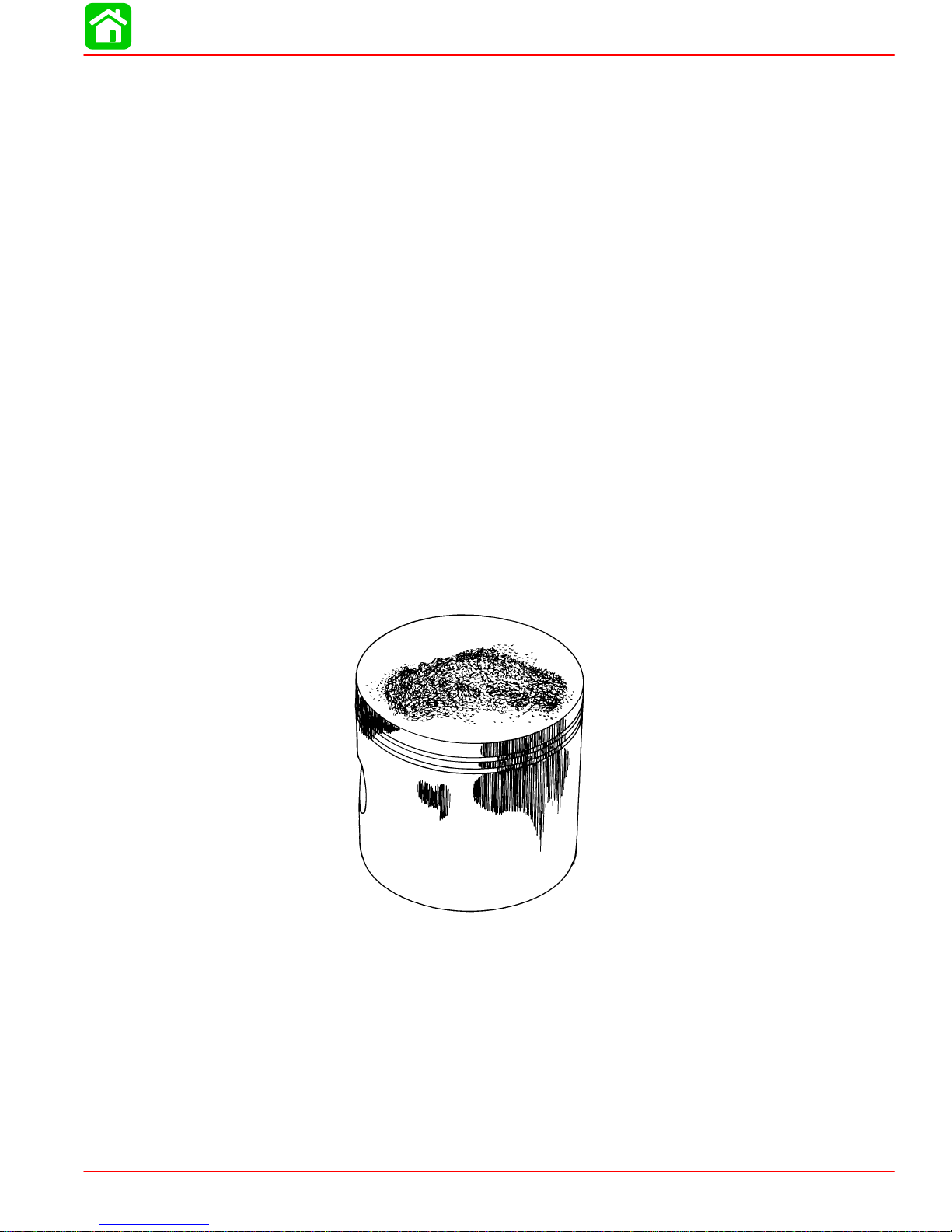
DETONATION
GENERAL INFORMATION
Detonation in a 4-cycle engine resembles the “pinging” heard in an automobile engine. It
can be otherwise described as a tin-like “rattling” or “plinking” sound.
Detonation is an explosion of an unburned portion of the fuel/air charge after the spark plug
has fired. Detonation creates severe shock waves in the engine, and these shock waves
often find or create a weakness: The dome of a piston, cylinder head/gasket, piston rings
or piston ring lands, piston pin and bearings.
A few of the most common causes of detonation in a marine 4-cycle application are as
follows:
• Over-advanced ignition timing.
• Use of low octane gasoline.
• Propeller pitch too high (engine rpm below recommended maximum range).
• Lean fuel mixture at or near wide-open-throttle.
• Spark plugs (heat range too hot - incorrect reach - cross-firing).
• Inadequate engine cooling (deteriorated cooling system).
• Combustion chamber/piston deposits (result in higher compression ratio).
Detonation usually can be prevented if:
1. The engine is correctly set up.
2. Diligent maintenance is applied to combat the detonation causes.
51115
Damaged Piston Resulting from Detonation
90-857138R1 MAY 2000 Page 1C-5

GENERAL INFORMATION
Following Complete Submersion
Submerged While Running (Special Instructions)
When an engine is submerged while running, the possibility of internal engine damage is
greatly increased. If, after engine is recovered and with spark plugs removed, engine fails
to turn over freely when turning flywheel, the possibility of internal damage (bent connecting
rod and/or bent crankshaft) exists. If this is the case, the powerhead must be disassembled.
Salt Water Submersion (Special Instructions)
Due to the corrosive effect of salt water on internal engine components, complete disassembly is necessary before any attempt is made to start the engine.
Fresh Water Submersion (Special Instructions)
1. Recover engine as quickly as possible.
2. Remove cowling.
3. Flush exterior of outboard with fresh water to remove mud, weeds, etc. DO NOT attempt
to start engine if sand has entered powerhead, as powerhead will be severely damaged.
Disassemble powerhead if necessary to clean components.
4. Drain engine oil. Do not refill engine oil at this time.
5. Drain carburetor and clean fuel pump assembly.
6. Remove spark plug and get as much water as possible out of powerhead. Most water
can be eliminated by placing engine in a horizontal position (with spark plug holes down)
and rotating flywheel.
7. Pour alcohol into carburetor throat (alcohol will absorbed water). Again rotate flywheel.
8. Turn engine over and pour alcohol into spark plug opening and rotate flywheel.
9. Turn engine over (place spark plug openings down) and pour engine oil into throat of
carburetor while rotating flywheel to distribute oil throughout crankcase.
10. Again turn engine over and pour approximately one teaspoon of engine oil into spark
plug opening. Again rotate flywheel to distribute oil in cylinder.
11. Dry all wiring and electrical components using compressed air.
12. Reinstall spark plug.
13. Refill engine crankcase with fresh oil.
14. Attempt to start engine, using a fresh fuel source. If engine starts, it should be run for
at least one hour to eliminate any water in engine.
15. If engine fails to start, determine cause (fuel, electrical or mechanical). Engine should
be run within 2 hours after recovery of outboard from water, or serious internal damage
may occur. If unable to start engine in this period, disassemble engine and clean all
parts. Apply oil as soon as possible.
Page 1C-6 90-857138R1 MAY 2000

Propeller Selection
For in-depth information on marine propellers and boat performance - written by marine engineers - see your Authorized Dealer for the illustrated “What You Should Know About
Quicksilver Propellers...and Boat Performance Information” (Part No. 90-86144).
For best all around performance from your outboard/boat combination, select a propeller
that all ows the engine to operate in the upper half of the recommended full throttle rpm range
with the boat normally loaded (refer to Specifications). This rpm range allows for better acceleration while maintaining maximum boat speed.
If changing conditions cause the rpm to drop below the recommended range (such as warmer, more humid weather, operation at higher elevations, increased boat load or a dirty boat
bottom/gear case) a propeller change or cleaning may be required to maintain performance
and ensure the outboard’s durability.
Check full-throttle rpm using an accurate tachometer with the engine trimmed out to a balanced-steering condition (steering effort equal in both directions) without causing the propeller to “break loose”.
Refer to “Quicksilver Accessory Guide” for a complete list of available propellers.
1. Select a propeller that will allow the engine to operate at or near the top of the recom-
mended full throttle rpm range (listed in “Specifications,” preceding) with a normal load.
Maximum engine speed (rpm) for propeller selection exists when boat speed is maximum and trim is minimum for that speed. (High rpm, caused by an excessive trim angle,
should not be used in determining correct propeller.) Normally, there is a 150-350 rpm
change between propeller pitches.
GENERAL INFORMATION
2. If full throttle operation is below the recommended range, the propeller MUST BE
changed to one with a lower pitch to prevent loss of performance and possible engine
damage.
3. After initial propeller installation, the following common conditions may require that the
propeller be changed to a lower pitch:
a. Warmer weather and great humidity will cause an rpm loss.
b. Operating in a higher elevation causes an rpm loss.
c. Operating with a damaged propeller or a dirty boat bottom or gear housing will cause
an rpm loss.
d. Operation with an increased load (additional passengers, equipment, pulling skiers,
etc.).
90-857138R1 MAY 2000 Page 1C-7
 Loading...