

Page 1

9.9 and 15 HP (4-Stroke)
Outboard Installation Manual
NOTICE To INSTALLER
After completing assembly, these
instructions should be placed with the
product for the owner’s future use.
IMPORT ANT: If the boat is to be water tested, the
operator should be familiar with the operation
procedures in the Operation and Maintenance
Manual.
Table of Contents
Boat Horsepower Capacity
U.S. COAST GUARD CAPACITY
MAXIMUM HORSEPOWER XXX
MAXIMUM PERSON
CAPACITY (POUNDS) XXX
MAXIMUM WEIGHT
CAPACITY XXX
Do not overpower or overload the boat. Most boats
will carry a required capacity plate indicating the maximum acceptable power and load as determined by
the manufacturer following certain federal guidelines.
If in doubt, contact your dealer or the boat manufacturer.
Installing Outboard 2. . . . . . . . . . . . . . . . . . . . . . . . . .
Steering Cable 2. . . . . . . . . . . . . . . . . . . . . . . . . . . . . .
Steering Cable Seal 2. . . . . . . . . . . . . . . . . . . . . . . . .
Steering Link Rod 3. . . . . . . . . . . . . . . . . . . . . . . . . . .
Wiring Harness 3. . . . . . . . . . . . . . . . . . . . . . . . . . . . .
Battery Cable Connections 4. . . . . . . . . . . . . . . . . . .
Shift and Throttle Cable 4. . . . . . . . . . . . . . . . . . . . . .
Propeller Installation 6. . . . . . . . . . . . . . . . . . . . . . . . .
WARNING
Using an outboard that exceeds the maximum
horsepower limit of a boat can: 1. cause loss of
boat control 2. place too much weight at the transom, altering the designed flotation characteristics of the boat or 3. cause the boat to break apart,
particularly around the transom area. Overpowering a boat can result in serious injury , death, or
boat damage.
Start in Gear Protection
The remote control connected to the outboard must
be equipped with a start-in-gear protection device.
This prevents the engine from starting in gear.
WARNING
Avoid serious injury or death from a sudden unexpected acceleration when starting your engine.
The design of this outboard requires that the remote control used with it must have a built in
start-in-gear protection device.
Selecting Accessories For
The Outboard
Genuine Quicksilver Parts and Accessories have
been specifically designed and tested for this outboard.
Some accessories not manufactured or sold by
Quicksilver are not designed to be safely used with
this outboard or outboard operating system. Acquire
and read the Installation, Operation, and Maintenance manuals for all selected accessories.
90-10203990 398- 1 -Printed in U.S.A.
Page 2
Installing Outboard
Steering Cable
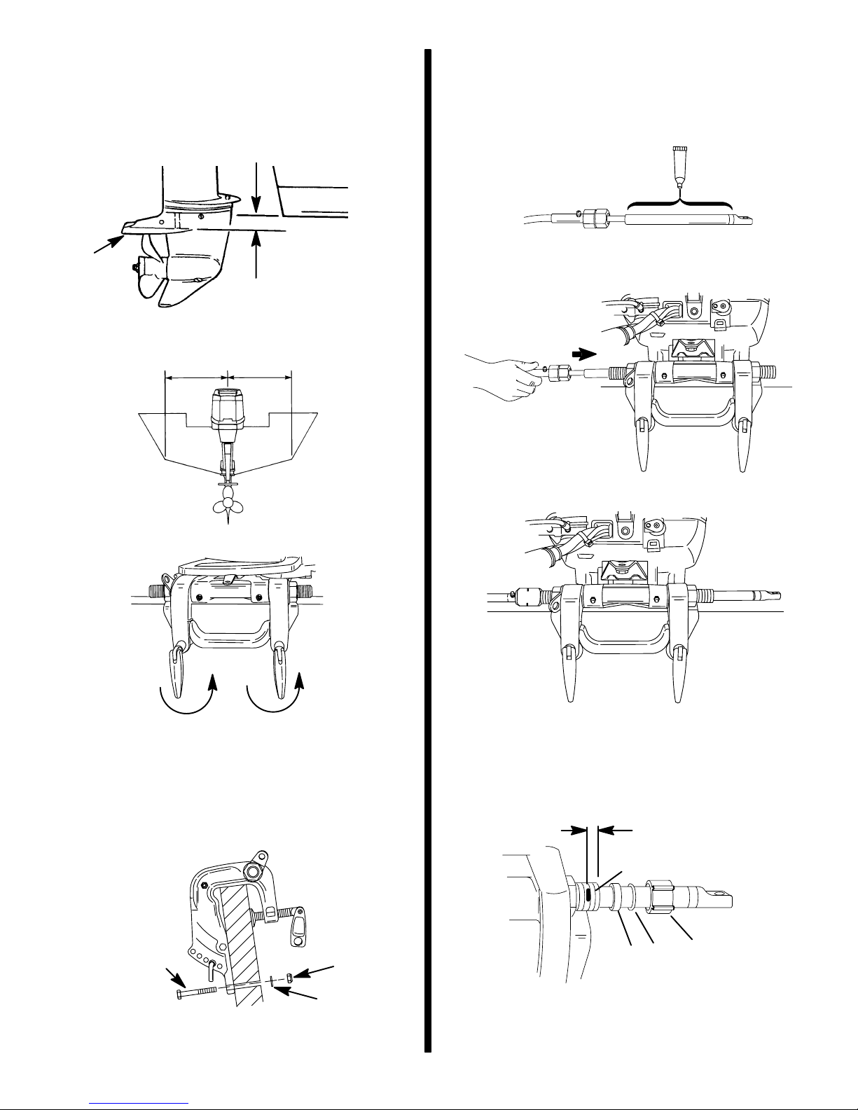
1. Measure the transom height of your boat. The
boat bottom should be aligned or be within 1 in.
(25mm) above the anti-ventilation plate (a) of the
outboard.
a
0-1in.
(0-25mm)
a - Anti-Ventilation Plate
2. Place outboard on center line of transom.
STARBOARD SIDE ROUTED CABLE
1. Lubricate the entire cable end.
a
a - Quicksilver 2-4-C Marine Lubricant with Teflon
2. Insert steering cable into tilt tube.
3. Torque nut to 35 lb. ft. (47.5 N·m).
3. Tighten transom clamp handles.
4. To prevent loss of outboard overboard, fasten
outboard by drilling two 5/16 in. (7.9 mm) holes
through the transom using transom clamp holes
as a template. Fasten with two bolts, flat washers
and locknuts. Use a marine waterproofing sealer
in holes and around bolts to make the installation
water tight.
Steering Cable Seal
1. Mark tilt tube 1/4 in. (6.4 mm) from end. Install
seal components.
1/4 in. (6.4mm)
a
a
a - Bolts (2)
b - Flat Washers (2)
c - Locknuts (2)
c
b
a - 1/4 in. (6.4 mm) Mark
b - Plastic Spacer
c - O-Ring Seal
d - Cap
- 2 -
b
d
c
Page 3

2. Thread cap to the mark.
Wiring Harness
Remote Wiring Harness Connection
to Engine
1. Apply Quicksilver Dielectric Grease inside the
connection.
2. Plug the remote wiring connector into the outboard wiring harness connector.
Steering Link Rod
1. Install steering link rod per illustration.
c
d
b
a
a - Special Bolt (10-90041) Torque to 20 lb. ft.(27.1 N·m)
b - Nylon Insert Locknut (11-34863) Torque to
20 lb. ft.(27.1 N·m)
c - Spacer (12-71970)
d - Flat Washer (2)
e - Nylon Insert Locknut (11-34863) Tighten Locknut Until it
Seats, Then Back Nut Off 1/4 Turn
f - Use Middle Hole
IMPORT ANT: The steering link rod that connects
the steering cable to the engine must be fastened
using special bolt (“a” - Part Number 10-90041)
and self locking nuts (“b”& “c”- Part Number
11-34863). These locknuts must never be replaced with common nuts (non locking) as they
will work loose and vibrate off, freeing the link rod
to disengage.
3. Secure the connection together with retainer, as
shown.
a - Remote Wiring Connector
b - Outboard Wiring Harness Connector
c - Retainer
WARNING
Disengagement of a steering link rod can result in
the boat taking a full, sudden, sharp turn. This potentially violent action can cause occupants to be
thrown overboard exposing them to serious injury or death.
- 3 -
Page 4

Battery Cable Connections
Shift and Throttle Cable
SINGLE OUTBOARD
a
(+)
b
(–)
a - Red Sleeve (Positive)
b - Black Sleeve (Negative)
c - Starting Battery
DUAL OUTBOARD
1. Connect a common ground cable (wire size same
as engine battery cables) between negative (–)
terminals on starting batteries.
c
Install cables into the remote control following the
instructions provided with the remote control.
NOTE: Install the shift cable to the engine first. The
shift cable is the first cable to move when the remote
control handle is moved out of neutral.
Shift Cable Installation
1. Position remote control into Forward gear.
F
2. Remove Cover.
(–)
d
(–)
d - Ground Cable (Same Wire Size As Engine Battery Cable –
Connect Between Negative (–) Terminals
a
a - Cover
3. Shift outboard into forward gear.
a
a - Rotate Shift Arm Forward
- 4 -
Page 5

4. Install cable to the shift lever. Secure with cable
latch.
5. Adjust the cable barrel so that it fits into the anchor
pocket.
b
Throttle Cable Installation
1. Position remote control into neutral.
N
2. Install throttle cable on pin. Lock in place with
cable latch.
3. Adjust cable barrel until the link rod is centered in
slot.
a
a - Cable Latch
b - Cable Barrel
6. Check shift cable adjustment as follows:
a. Shift remote control into forward. The propel-
ler shaft should be locked in gear. If not, adjust
the barrel closer to the cable end.
b. Shift remote control into neutral. The propel-
ler shaft should turn freely without drag. If not,
adjust the barrel away from the cable end. Repeat steps a and b.
c. Shift remote control into reverse while turning
propeller. The propeller shaft should be
locked in gear. If not, adjust the barrel away
from the cable end . Repeat steps a thru c.
d. Shift remote control back to neutral. The pro-
peller shaft should turn freely without drag. If
not, adjust the barrel closer to the cable end.
Repeat steps a thru d.
c
a
a - Shift Cable
b - Cable Barrel
c - Link Rod – Adjust Barrel so Link Rod is Centered in Slot
IMPORTANT: After installation, move the remote
control handle a few times from the neutral position to the wide-open-throttle position in forward
gear. Move handle back to neutral and visually
Check that the link rod is still centered. If necessary, readjust the barrel.
4. Reinstall Cover.
b
a
a - Cover
- 5 -
Page 6

Propeller Installation
Big Foot Gear Case
Standard Gear Case
WARNING
If the propeller shaft is rotated while the engine is
in gear, there is the possibility that the engine will
crank over and start. T o prevent this type of accidental engine starting and possible serious injury caused from being struck by a rotating propeller, always shift outboard to neutral position and
remove spark plug leads when you are servicing
the propeller.
Flo-Torq I Drive Hub Propellers
c
d
a - Forward Thrust Hub
b - Propeller
c - Rear Thrust Hub
d - Propeller Nut – Tighten
a
b
WARNING
If the propeller shaft is rotated while the engine is
in gear, there is the possibility that the engine will
crank over and start. T o prevent this type of accidental engine starting and possible serious injury caused from being struck by a rotating propeller, always shift outboard to neutral position and
remove spark plug leads when you are servicing
the propeller.
Flo-Torq I Drive Hub Propellers
c
a - Forward Thrust Hub
b - Propeller
c - Propeller Nut – Tighten
Flo-Torq II Drive Hub Propellers
e
d
a
b
Flo-Torq II Drive Hub Propellers
d
e
c
a - Forward Thrust Hub
b - Replaceable Drive Sleeve
c - Propeller
d - Rear Thrust Hub
e - Propeller Nut – Tighten
c
a - Forward Thrust Hub
b - Propeller
c - Replaceable Drive Sleeve
d - Rear Thrust Hub
e - Propeller Nut
a
b
a
b
- 6 -
 Loading...