

Page 1

Cleanliness and Care of
Service Manual Outline
Outboard Motor
A marine power product is a combination of many machined, honed, polished and lapped surfaces with tolerances that are measured in the ten thousands of an
inch./mm When any product component is serviced, care
and cleanliness are important. Throughout this manual, it
should be understood that proper cleaning, and protection
of machined surfaces and friction areas is a part of the repair procedure. This is considered standard shop practice
even if not specifically stated.
Whenever components are removed for service, they
should be retained in order. At the time of installation, they
should be installed in the same locations and with the same
mating surfaces as when removed.
Before raising or removing and outboard engine from a
boat, the following precautions should be adhered to:
(1) Check that flywheel is secured to end of crankshaft with
a locknut and lifting eye is threaded into flywheel a minimum of 5 turns.
(2) Connect a hoist of suitable strength to the lifting eye.
In addition, personnel should not work on or under an out-
board which is suspended. Outboards should be attached
to work stands, or lowered to ground as soon as possible.
We reserve the right to make changes to this manual without prior notification.
Refer to dealer service bulletins for other pertinent information concerning the products described in this manual.
Section 1 - General Information & Specifications
Section 2 - Electrical & Ignition
Part A - Ignition System
Part B - Battery, Charging System &
Starting System
Part C - T iming/Synchronizing &
Adjusting
Part D - Wiring Diagrams
Section 3 - Fuel Systems
Part A - Carburetion
Part B - Fuel Pump
Part C - Fuel Enrichment
Part D - Oil Injection
Section 4 - Powerhead
Section 5 - Mid-Section
Part A - Clamp/Swivel Brackets and
Driveshaft Housing
Part B - Power Trim (Design I)
Part C - Power Trim (Design II)
Part D - Power Trim (Design III)
Part E - Power Trim (Design IV)
Part F - Manual Tilt (Design I, II, III)
Part G - Manual Tilt (Design IV)
Section 6 - Lower Unit
Part A - Standard Gear Housing
Part B - 60 Big Foot, 60 SeaPro &
Marathon Gear Housing
Part C - Jet Drive
Section 7 - Outboard Installation/
Attachments
Part A - Ride-Guide Steering -
Throttle/Shift Cables &
Electrical Connections
Part B - Tiller Handle and Co-Pilot
Part C - Rewind Starter
ii
90-817643R1 DECEMBER 1996
Page 2

Notice
Throughout this publication, “Dangers”, “Warnings” and
“Cautions” (accompanied by the International HAZARD
Symbol ) are used to alert the mechanic to special instructions concerning a particular service or operation that
may be hazardous if performed incorrectly or carelessly.
OBSERVE THEM CAREFULLY!
These “Safety Alerts” alone cannot eliminate the hazards
that they signal. Strict compliance to these special instructions when performing the service, plus “Common Sense”
operation, are major accident prevention measures.
! DANGER
DANGER - Immediate hazards which WILL result in severe personal injury or death.
! WARNING
WARNING - Hazards or unsafe practices which COULD
result in severe personal injury or death.
!
Hazards or unsafe practices which could result in minor personal injury or product or property damage.
!
CAUTION
We could not possibly know of and advise the service trade
of all conceivable procedures by which a service might be
performed and of the possible hazards and/or results of
each method. We have not undertaken any such wide evaluation. Therefore, anyone who uses a service procedure
and/or tool, which is not recommended by the manufacturer, first must completely satisfy himself that neither his nor
the products safety will be endangered by the service procedure selected.
All information, illustrations and specifications contained in
this manual are based on the latest product information
available at the time of publication. As required, revisions
to this manual will be sent to all dealers contracted by us
to sell and/or service these products.
It should be kept in mind, while working on the product, that
the electrical system and ignition system are capable of violent and damaging short circuits or severe electrical
shocks. When performing any work where electrical terminals could possibly be grounded or touched by the mechanic, the battery cables should be disconnected at the
battery.
Any time the intake or exhaust openings are exposed during service they should be covered to protect against accidental entrance of foreign material which could enter the
cylinders and cause extensive internal damage when the
engine is started.
Notice to Users of This
Manual
This service manual has been written and published by the
Service Department of Mercury Marine to aid our dealers’
mechanics and company service personnel when servicing the products described herein.
It is assumed that these personnel are familiar with the
servicing procedures of these products, or like or similar
products manufactured and marketed by Mercury Marine,
that they have been trained in the recommended servicing
procedures of these products which includes the use of
mechanics’ common hand tools and the special Mercury
Marine or recommended tools from other suppliers.
It is important to note, during any maintenance procedure
replacement fasteners must have the same measurements and strength as those removed. Numbers on the
heads of the metric bolts and on the surfaces of metric nuts
indicate their strength. American bolts use radial lines for
this purpose, while most American nuts do not have
strength markings. Mismatched or incorrect fasteners can
result in damage or malfunction, or possibly personal injury. Therefore, fasteners removed should be saved for reuse in the same locations whenever possible. Where the
fasteners are not satisfactory for re-use, care should be
taken to select a replacement that matches the original.
90-817643R1 DECEMBER 1996
i
Page 3
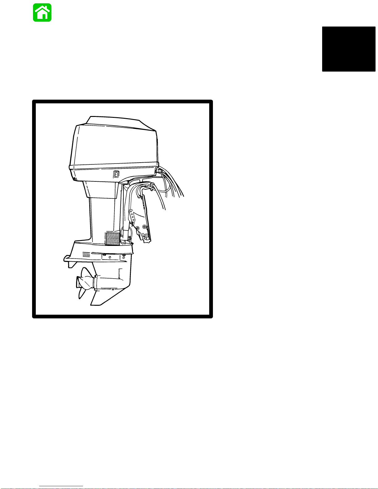
GENERAL INFORMATION
and SPECIFICATIONS
1
50557
Page 4

Table of Contents
Propeller Information 1-1. . . . . . . . . . . . . . . . . . . . . . . . . . .
How To Use This Manual 1-1. . . . . . . . . . . . . . . . . . . . . . . .
Page Numbering 1-1. . . . . . . . . . . . . . . . . . . . . . . . . . . . . . .
Master Specifications 1-2. . . . . . . . . . . . . . . . . . . . . . . . . . .
Powerhead 1-4. . . . . . . . . . . . . . . . . . . . . . . . . . . . . . . . . . . .
Specifications 1-4. . . . . . . . . . . . . . . . . . . . . . . . . . . . . . .
Special Tools 1-4. . . . . . . . . . . . . . . . . . . . . . . . . . . . . . .
Cowl Removal 1-5. . . . . . . . . . . . . . . . . . . . . . . . . . . . . .
Filling Oil Injection System 1-5. . . . . . . . . . . . . . . . . . . .
Propeller Selection 1-6. . . . . . . . . . . . . . . . . . . . . . . . . .
Propeller Installation 1-6. . . . . . . . . . . . . . . . . . . . . . . . .
Trim “In” Angle Adjustment 1-7. . . . . . . . . . . . . . . . . . .
Propeller Information Chart 1-8. . . . . . . . . . . . . . . . . . .
50/55 models 1-8. . . . . . . . . . . . . . . . . . . . . . . . . . . .
60 models 1-8. . . . . . . . . . . . . . . . . . . . . . . . . . . . . . .
Propeller Information Chart 1-9. . . . . . . . . . . . . . . . . . .
60 Big foot, 60 SeaPro/Marathon 1-9. . . . . . . . . . .
50-60 Models 1-9. . . . . . . . . . . . . . . . . . . . . . . . . . . .
Stainless Steel Race Propellers –
Available from Mercury Performance
Products 1-9. . . . . . . . . . . . . . . . . . . . . . . . . . . . . . .
General Information: 1-9. . . . . . . . . . . . . . . . . . . . . .
Power Trim System
(Models with Power Trim) 1-10. . . . . . . . . . . . . . . . . . .
General Information 1-10. . . . . . . . . . . . . . . . . . . . . .
Checking Trim System Fluid Level 1-11. . . . . . . . .
Trimming (Models with Power Trim) 1-11. . . . . . . . . . .
Trimming Outboard “Out” (“Up”) 1-11. . . . . . . . . . .
Trimming Outboard “In” (“Down”) 1-11. . . . . . . . . .
Trim Tab Adjustment 1-12. . . . . . . . . . . . . . . . . . . . . . . .
Boat Performance 1-12. . . . . . . . . . . . . . . . . . . . . . . . . .
Test Instructions 1-12. . . . . . . . . . . . . . . . . . . . . . . .
Page
Page
Lubrication Points 1-14. . . . . . . . . . . . . . . . . . . . . . . . . . . . .
Ride Guide Steering Cable and Pivot
Point Lubrication 1-15. . . . . . . . . . . . . . . . . . . . . . .
Gear Housing Lubrication 1-16. . . . . . . . . . . . . . . . .
Salt Water Corrosion - Gear Housing
Bearing Carrier and Cover Nut 1-16. . . . . . . . . .
Periodic Inspection 1-17. . . . . . . . . . . . . . . . . . . . . . . . .
Flushing Outboard Cooling System 1-17. . . . . . . . . . .
Following Complete Submersion 1-18. . . . . . . . . . . . .
Salt Water Submersion (Special
Instructions) 1-18. . . . . . . . . . . . . . . . . . . . . . . . . . .
Submerged While Running (Special
Instructions) 1-18. . . . . . . . . . . . . . . . . . . . . . . . . . .
Submerged Engine (Fresh Water)
(Plus Special Instructions) 1-18. . . . . . . . . . . . . .
Out-of-Season Outboard Storage 1-19. . . . . . . . . . . . .
Out-of-Season Battery Storage 1-19. . . . . . . . . . . . . . .
How Weather Affects Engine Performance 1-20. . . . .
Conditions Affecting Operation 1-21. . . . . . . . . . . . . . .
Detonation: Causes and Prevention 1-21. . . . . . . . . .
Compression Check 1-21. . . . . . . . . . . . . . . . . . . . . . . .
Water Pressure Check 1-22. . . . . . . . . . . . . . . . . . . . . .
Serial Number Location 1-22. . . . . . . . . . . . . . . . . . . . .
Painting Procedures 1-23. . . . . . . . . . . . . . . . . . . . . . . . . . .
Decal Application 1-24. . . . . . . . . . . . . . . . . . . . . . . . . . . . . .
1-0 - GENERAL INFORMA TION and SPECIFICATIONS 90-817643R1 DECEMBER 1996
Page 5
Propeller Information
For in-depth information on marine propellers and boat
performance – written by marine engineers – see your Authorized Dealer for the illustrated “What Y ou Should Know
About Quicksilver Propellers... and Boat Performance Information” (Part No. 90-86144).
How To Use This Manual
Section Section Heading
1 General Information and Specifications
2 Electrical & Ignition
3 Fuel Systems
4 Powerhead
5 Mid-Section
6 Lower Unit
7 Outboard Installation/Attachments
The manual is divided into SECTIONS (shown, right) which
represents major components and systems.
Some SECTIONS are further divided into PARTS. Each
P ART has a title page. A “T able of Contents” for the particular PART is printed on the back of the title page.
SECTIONS and P AR TS are listed on the “Service Manual
Outline” sheet which immediately follows the cover of this
book.
EXAMPLE:
EXAMPLE:
Page Numbering
Two number groups appear at the bottom of each page.
The example, below, is self-explanatory.
90-817643R2 DECEMBER 1996
Revision No. 2
Month of Printing
Year of Printing
LOWER UNIT - 6A-7
Section Description
Section Number
Part of Section Letter
Page Number
GENERAL INFORMATION and SPECIFICATIONS - 1-190-817643R1 DECEMBER 1996
Page 6

Master Specifications
Model 45 Jet/50/55 Marathon-Seapro/60/60 Marathon-Seapro/60 Bigfoot
HORSEPOWER
(KW)
OUTBOARD
WEIGHT
CYLINDER
BLOCK
STROKE Length 2.520 in. (64.008mm)
CYLINDER
BORE
PISTON Piston Type
REEDS Reed Stand 0pen (Max.)
Model 50
Model 55
Model 60
Model 45 Jet
Electric Start (ELPTO)
(ELO)
Manual Start (ML)
Type
Displacement
Diameter (Std)
Taper/Out of Round Maximum
Bore Type
Standard
0.015 in. (0.381mm) Oversize
0.030 in. (0.762) Oversize
Reed Stop (Max.)
Reed Thickness
– 45 Jet/50/60
– 55
50 (37)
55 (41)
60 (45)
60 (45)
217.0 lbs. (98.4kg)
213.0 lbs. (96.6kg)
213.0 lbs. (96.6kg)
Two-Stoke Cycle – Loop Charged
51.8 cu. in. (849cc)
2.955 in. (75.057mm)
0.003 in. (0.076mm)
Cast Iron
Aluminum
2.950 in. (74.93 mm)
2.965 in. (75.31 mm)
2.980 in. (75.69 mm)
0.020 in. (0.50mm)
Not Adjustable
0.008 in. (0.203mm)
0.010 in. (0.254mm)
GEAR
HOUSING
FUEL
SYSTEM
50/55/60
Gear Ratio
Gearcase Capacity
Forward Gear - No. of Teeth
Pinion Gear - No. of Teeth
Pinion Height
Forward Gear Backlash
Water Pressure
– @ Idle
– @ WOT
60 SeaPro/Marathon, 60 Bigfoot
Gear Ratio
Gearcase Capacity
Forward Gear - No. of Teeth-Type
Pinion Gear - No. of Teeth-Type
Pinion Height
Forward Gear Backlash
Water Pressure @ RPM
Fuel
Recommended Gasoline
Recommended Oil
Gasoline/Oil Ratio
Fuel Pressure – @ Idle
– @ WOT
1.64:1
11.5 fl. oz. (340ml)
23
14
0.025 in. (0.64mm)
0.013 in. – 0.019 in.
(0.33mm – 0.48mm)
1 – 3 PSI
7 – 12 PSI
2.3:1
22.5 fl. oz. (655ml)
30
13
0.025 in. (0.64mm)
0.012 in. to 0.019 in. (0.30mm to 0.48mm)
10 to 15 PSI (69 to 103 kPa) @ 5250 RPM
Pre-Mixed Gasoline and Oil
Unleaded 87 Octane Minimum
Quicksilver TC-W II or TC-W3 2 Cycle
Outboard Oil
50:1 (25:1 Break-In)
3-1/2 PSI
6 PSI
1-2 - GENERAL INFORMA TION and SPECIFICATIONS 90-817643R1 DECEMBER 1996
Page 7

Model 45 Jet/50/55 Marathon-Seapro/60/60 Marathon-Seapro/60 Bigfoot
STARTING
SYSTEM
IGNITION
SYSTEM
CHARGING
SYSTEM
C
A
R
B
U
R
E
T
O
R
Manual Start – All Models
Electric Start – Optional – All Models
Starter Draw (Under Load)
Battery Rating
Type
Spark Plug Type
Spark Plug Gap
Alternator Output
Electric Models
Manual Models (Not Regulated)
Idle RPM
Wide Open Throttle (WOT) RPM
Idle Mixture Screw Adjustment
(Preset - Turns Out)
Model 50
All Other Models
Float Adjustment
Float Level
Recoil Starter
125 Amperes
Min. Reserve Cap. Rating of 100 Min. and
CCA of 350 Amperes
Capacitor Discharge
NGK BP8H-N-10
0.040 in. (1.0mm)
16 Amperes @ 3000 RPM
14 Amperes @ 300 RPM
9 Amperes @ 3000 RPM
675 ± 25
5000 – 5500
1-1/8 ± 1/4
1-1/2 ± 1/4
7/16 in. (11.2mm)
OIL
INJECTION
T
I
M
I
N
G
Main Jet
– Model 50 (WME – 43)
– Model 55/60 Seapro-Marathon
(WME – 44)
– Model 45 Jet/60 (WME – 45)
Vent Jet
– Model 50 (WME – 43)
– Model 55/60 Seapro-Marathon
(WME – 44)
– Model 45 Jet/60 (WME – 45)
Recommended Oil
Oil Tank Capacity/Approx. Time
Reserve Capacity/Approx. Time
Output @ 1500 RPM for 10 Minutes
with Pump @ Full Open
Idle
Maximum BTDC
@ Cranking Speed
– Model 50/60
– Model 55/60 Seapro-Marathon
@ 5000 RPM
– Model 50/60
– Model 55/60 Seapro-Marathon
.048 in.
.060 in.
.062 in.
.090 in.
None
.090 in.
Quicksilver TC-W II or TC-W 3
3.0 qts. (2.8L) 7 hrs.
14.5 fl. oz. (0.43L) 1/2 hr.
10.0cc ± 3cc
2° – 6° ATDC
24° BTDC
18° BTDC
22° BTDC
16° BTDC
GENERAL INFORMATION and SPECIFICATIONS - 1-390-817643R1 DECEMBER 1996
Page 8
Powerhead
Specifications
Block
Type 3 Cylinder, 2 Cycle. . . . . . . . . . . . . . . . . . .
Displacement
50/55/60 Horsepower 51.8 cu in. (849 cc).
Reed Block
Reed Stop Opening (Max.) 0.020 in. . . . . . . .
(0.50 mm)
Crankshaft
Runout (Max.) 0.003 in. (0.08 mm). . . . . . . . . .
Taper (Max.) 0.003 in. (0.08 mm). . . . . . . . . . .
Firing Order 1-3-2. . . . . . . . . . . . . . . . . . . . . . . . . .
Cylinder Bore
Dia. Standard 2.955 in. (75.057 mm). . . . . . . . . . .
Dia. .015 in. Oversize 2.970 in. (75.438 mm). . . .
Dia. .030 in. Oversize 2.985 in. (75.819 mm). . . .
Out of Round (Max.) 0.003 in. (0.076 mm). . . . .
Taper (Max.) 0.003 in. (0.076 mm). . . . . . . . . . . .
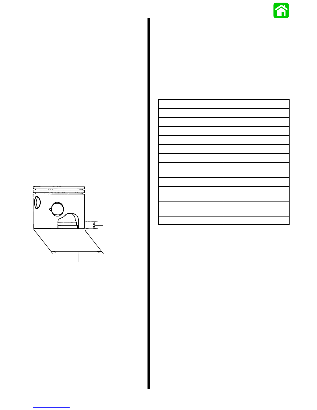
Piston
Dia. Standard 2.950 in. (74.93 mm). . . . . . . . . . .
Dia. .015 in. Oversize 2.965 in. (75.31 mm). . . .
Dia. .030 in. Oversize 2.980 in. (75.69 mm). . . .
IMPORTANT: Measure piston skirt at right angle (90°)
to piston pin center line, 0.50 in. (12.7mm) up from bottom edge of skirt.
0.50 in.
(12.7mm)
Special Tools
Description Part Number
Flywheel Holder 91–52344
Protector Cap 91-24161
Flywheel Puller 91-73687A1
Lifting Eye 91-90455
Piston Ring Expander 91-24697
Piston Pin Tool 91-74607A2
Lock Ring Installation
Tool
Powerhead Stand 91-25821A1
*Torque Wrench (0–200
lb. ft.)
*Torque Wrench (0–150
lb. in.)
Compression Tester 91-29287
*May be Obtained Locally
91-77109A1
91-32610
91-66274
PISTON PISTON SKIRT CYLINDER BORE
SIZE DIAMETER FINISH HONE
Standard 2.950 in. 2.955 in.
Piston (74.93 mm) (75.057mm)
0.015 in. 2.965 in. 2.970 in.
(0.381 mm) (75.31 mm) (75.438 mm)
Oversize
0.030 in. 2.980 in. 2.985 in.
(0.752 mm) (75.69 mm) (75.819 mm)
Oversize
1-4 - GENERAL INFORMA TION and SPECIFICATIONS 90-817643R1 DECEMBER 1996
Page 9
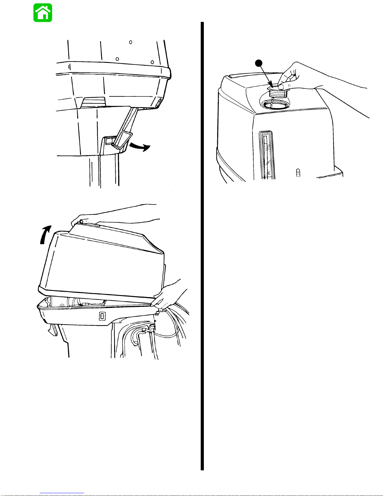
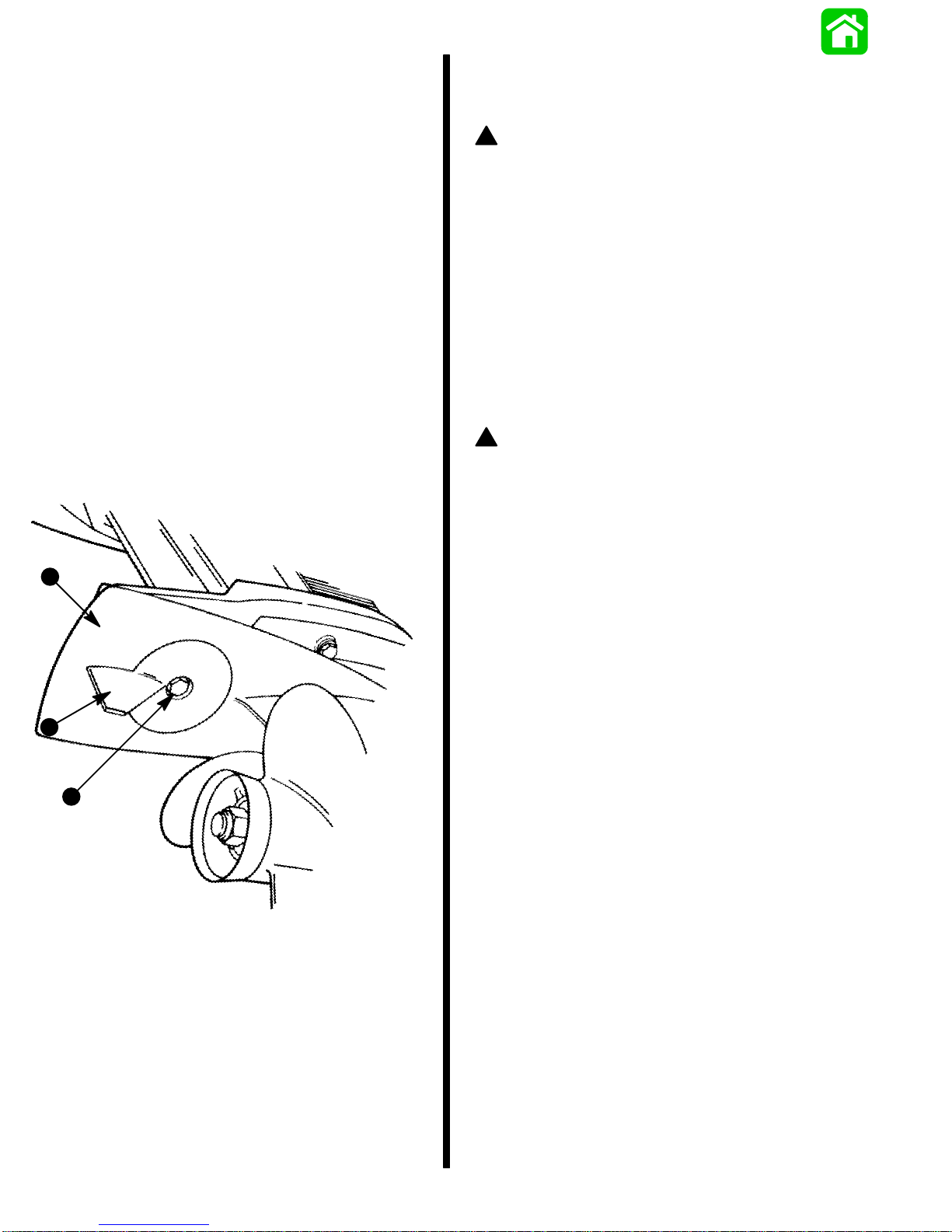
Cowl Removal
Filling Oil Injection System
Remove fill cap (a) from the oil tank and fill tank with oil. Retighten the fill cap.
a
50553
50554
50552
Use Quicksilver NMMA Certified TC-W3 or TC-WII 2-Cycle
Outboard Oil.
• Quicksilver Certified TC-W3 Outboard Oil is a higher
grade oil that provides increased lubrication and extra
resistance to carbon buildup when used with good or varying grades of gasoline.
• Quicksilver Certified TC-WII Outboard Oil is an industry
leading oil that provides superior outboard lubrication
and resistance to carbon buildup when used with good
grades of gasoline.
Periodically consult with your dealer to get the latest gasoline and oil recommendations. If Quicksilver 2-Cycle Outboard Oil is not available, substitute a 2-Cycle outboard
manufacturers oil that is NMMA Certified TC-W3 or TCWII, or another brand of 2-Cycle outboard oil that is NMMA
Certified TC-W3 or TC-WII. The use of an inferior 2-Cycle
outboard oil can reduce engine durability. Damage from
use of inferior oil may not be covered under the limited warranty .
GENERAL INFORMATION and SPECIFICATIONS - 1-590-817643R1 DECEMBER 1996
Page 10
Propeller Selection
Propeller Installation
1. Select a propeller that will allow the engine to operate
at or near the top of the recommended full throttle RPM
range (listed in “Specifications,” preceding) with a normal load. Maximum engine speed (RPM) for propeller
selection exists when boat speed is maximum and trim
is minimum for that speed. (High RPM, caused by an
excessive trim angle, should not be used in determining correct propeller.) Normally, there is a 150-350
RPM change between propeller pitches.
2. If full throttle operation is below the recommended
range, the propeller MUST BE changed to one with a
lower pitch to prevent loss of performance and possible engine damage.
3. For better acceleration, such as is needed in water
skiing, changing to a different pitch to increase the
engine speed to 500 RPM above the recommended
range is advised. Continuous operation above the recommended maximum RPM, however, is not permissible.
4. After initial propeller installation, the following common
conditions may require that the propeller be changed
to a lower pitch:
a. Warmer weather and great humidity will cause an
RPM loss.
b. Operating in a higher elevation causes an RPM
loss.
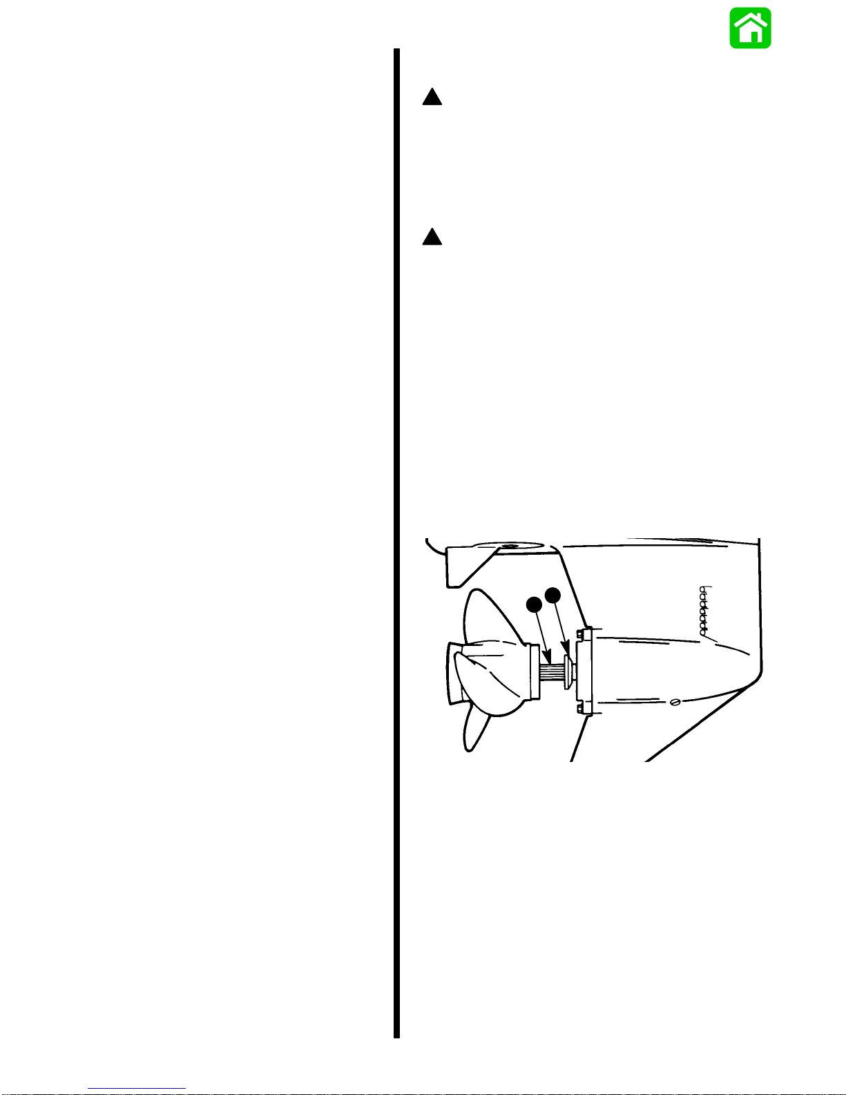
! WARNING
T o avoid accidental starting, which could result in personal injury, remove spark plug leads from spark
plugs before working near propeller. Place a block of
wood between the anti-ventilation plate and propeller
to protect hands from propeller blades while tightening propeller nut.
!
CAUTION
If the propeller moves forward-and-aft on the propeller
shaft (is loose), retighten the propeller nut. Operation
with a loose propeller could cause damage to the
thrust hub and gear housing during acceleration, deceleration or when shifting gears.
IMPORTANT: To assure that the propeller remains secure on the shaft during the season, periodically
check propeller shaft nut for tightness.
1. To aid in future removal of the propeller, liberally coat
the propeller shaft spline with one of the following
Quicksilver lubricants:
– Anti-Corrosion Grease
– 2-4-C Marine Lubricant
– Special Lubricant 101
2. Place forward thrust hub on propeller shaft.
c. Operating with a damaged propeller or a dirty boat
bottom or gear housing will cause an RPM loss.
d. Operation with an increased load (additional pas-
sengers, equipment, pulling skiers, etc.).
a - Thrust Hub
b - Propeller Shaft
a
b
50551
1-6 - GENERAL INFORMA TION and SPECIFICATIONS 90-817643R1 DECEMBER 1996
Page 11
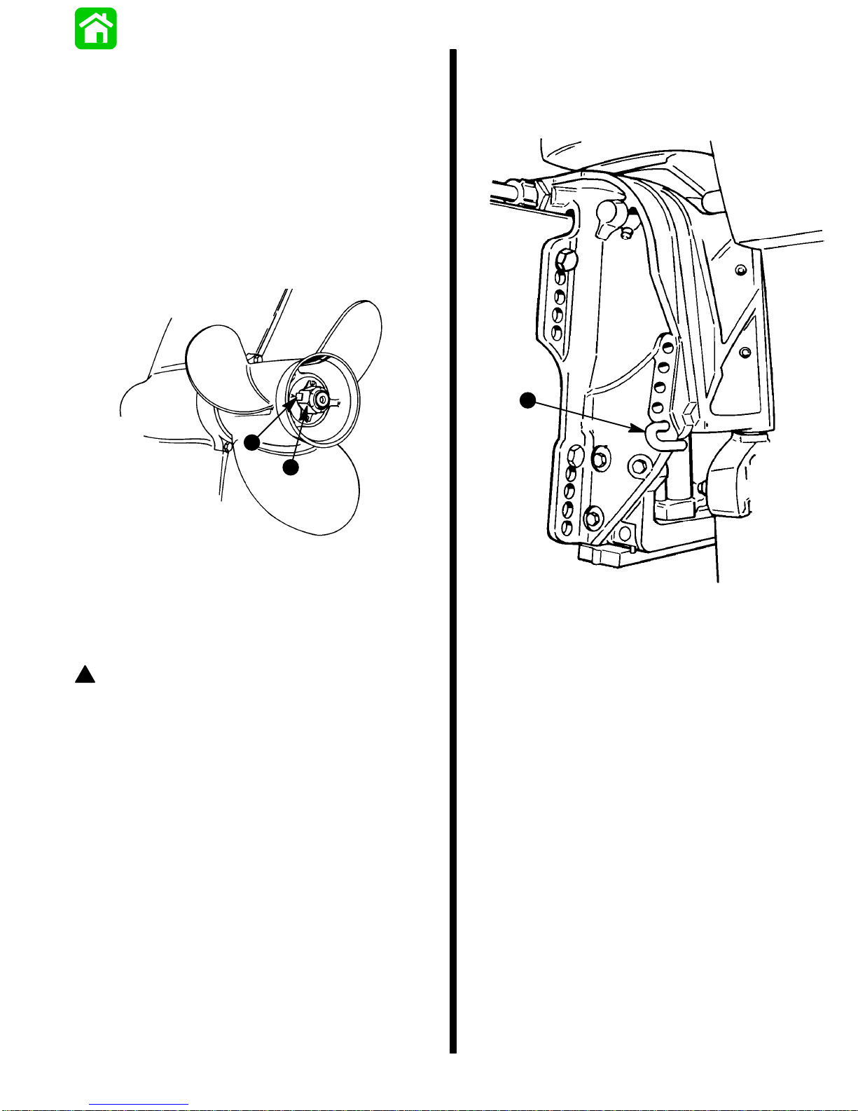
3. While aligning splines, place Quicksilver propeller and
tab washer on propeller shaft in this order.
4. T o prevent propeller from rotating, place a flat block of
wood between the anti-ventilation plate and the
propeller.
5. Thread propeller nut on propeller shaft, tighten securely with wrench [minimum of 55 lb. ft. (74.5 N·m) of
torque] and bend on tab washer to secure propeller
nut.
6. After first use, bend the tab straight, retighten propeller
nut [minimum of 55 lb. ft. (74.5 N⋅m) of torque] and
again bend tab washer to secure nut. Check propeller
periodically for tightness.
c
Water test the boat not using the trim adjustment pin. If undesirable and/or unsafe steering conditions are experienced (boat runs with nose down), install trim adjustment
pin in proper hole to prevent unsafe handling characteristics.
a
d
51119
c - Tab Washer
d - Propeller Nut
Installing and Removing Propeller
Trim “In” Angle Adjustment
! WARNING
Operating some boats with outboard trimmed to the
full “in” trim angle [not using trim adjustment bolt (a)]
at planing speed will cause undesirable and/or unsafe
steering conditions. Each boat must be water tested
for handling characteristics after outboard installation
and after any trim adjustments.
IMPORTANT: Some boat/outboard combinations, that
do not use the trim adjustment pin (a) and are trimmed
to the full “in” trim angle, will not experience any undesirable and/or unsafe steering conditions during planing speed. Thus, not using trim adjustment pin may be
desired. However, some boats with outboard trimmed
to the full “in” trim angle at planing speeds will cause
undesirable and/or unsafe steering conditions. If
these steering conditions are experienced, under no
circumstances should the outboard be operated without the trim adjustment pin and without the pin adjusted in the proper holes to prevent unsafe handling
characteristics.
50157
GENERAL INFORMATION and SPECIFICATIONS - 1-790-817643R1 DECEMBER 1996
Page 12

Propeller Information Chart
50/55 MODELS
Wide Open Throttle RPM: 5000-5500
Recommended Transom Height: Short Shaft 16-1/2 in. (41.9 cm), Long Shaft 21 in. (53.3 cm)
Right Hand Rotation
Gear Reduction: 1.64:1
Thrust Hub: 73345A 1
Approx. Approx. Speed
No. of Gross Boat Boat Range Propeller
Diameter Pitch Blades Material Wgt. (Lbs.) Length (MPH) Part Number
10″ 19″ 3 Alum Up to 700 Up to 14′ 48-55 48-73146A400
10″ 17″ 3 Alum Up to 800 Up to 15′ 44-51 48-73144A400
10″ 16″ 3 Steel 700-900 Up to 15′ 41-48 48-91818A500
10″ 16″ 3 Alum 700-900 Up to 15′ 41-48 48-73142A400
10.13″ 15″ 3 Steel 800-1100 13′ to 15′ 38-45 48-76232A500
10.13″ 15″ 3 Alum 800-1100 13′ to 15′ 38-45 48-73140A400
10.38″ 14″ 3 Alum 900-1300 14′ to 16′ 35-41 48-816706A40
10-1/4″ 14″ 3 Steel 900-1300 14′ to 16′ 35-41 48-76230A500
10.38″ 13″ 3 Steel 1000-1500 14′ to 17′ 32-38 48-76228A500
10-1/2″ 13″ 3 Alum 1000-1500 14′ to 17′ 32-38 48-816704A40
10.63″ 12″ 3 Steel 1100-1700 15′ to 17′ 28-34 48-79792A500
10-3/4″ 12″ 3 Alum 1100-1700 15′ to 17′ 28-34 48-816702A40
10.88″ 11″ 3 Alum 1200-1900 16′ to 18′ 24-30 48-85632A400
12″ 10-1/2″ 3 Alum 1400-2100 16′ + 22-28 48-42740A100
11-1/4″ 10″ 3 Alum 1500-2300 17′ + 20-26 48-73132A400
12-1/4″ 9″ 3 Steel 1800 + 18′ + 14-22 48-97868A500
12-1/4″ 9″ 3 Alum 1800 + 18′ + 14-22 48-87818A100
12-1/2″ 8″ 3 Alum 2100 + 18′ + 01-18 48-42738A100
60 MODELS
Wide Open Throttle RPM: 5000-5500
Recommended Transom Height: Short Shaft 16-1/2 in. (41.9 cm), Long Shaft 20 in. (53.3 cm)
Right Hand Rotation
Gear Reduction: 1.64:1
Thrust Hub: 73345A 1
Approx. Approx. Speed
No. of Gross Boat Boat Range Propeller
Diameter Pitch Blades Material Wgt. (Lbs.) Length (MPH) Part Number
10″ 19″ 3 Alum Up to 8000 Up to 14′ 48-55 48-73146A400
10″ 17″ 3 Alum Up to 1000 Up to 15′ 44-51 48-73144A400
10″ 16″ 3 Steel 700-1100 Up to 15′ 41-48 48-91818A500
10″ 16″ 3 Alum 700-1100 Up to 15′ 41-48 48-73142A400
10.13″ 15″ 3 Steel 800-1200 13′ to 15′ 38-45 48-76232A500
10.13″ 15″ 3 Alum 800-1200 13′ to 15′ 38-45 48-73140A400
10.38″ 14″ 3 Alum 900-1500 14′ to 16′ 35-41 48-816706A40
10-1/4″ 14″ 3 Steel 900-1500 14′ to 16′ 35-41 48-76230A500
10.38″ 13″ 3 Steel 1200-1800 15′ to 17′ 32-38 48-76228A500
10-1/2″ 13″ 3 Alum 1200-1800 15′ to 17′ 32-38 48-816704A40
10.63″ 12″ 3 Steel 1500-2100 16′ to 18′ 28-34 48-79792A500
10-3/4″ 12″ 3 Alum 1500-2100 16′ to 18′ 28-34 48-816702A40
10.88″ 11″ 3 Alum 1800-2400 16′ to 18′ 24-30 48-85632A400
12″ 10-1/2″ 3 Alum 2000-2600 17′ + 22-28 48-42740A100
11-1/4″ 10″ 3 Alum 2100-2600 17′ + 20-26 48-73132A400
12-1/4″ 9″ 3 Steel 2400 + 18′ + 14-22 48-97868A500
12-1/4″ 9″ 3 Alum 2400 + 18′ + 14-22 48-87818A100
12-1/2″ 8″ 3 Alum 2800 + 19′ + 01-18 48-42738A100
1-8 - GENERAL INFORMA TION and SPECIFICATIONS 90-817643R1 DECEMBER 1996
Page 13

Propeller Information Chart
60 BIG FOOT, 60 SEAPRO/MARATHON MODELS
Wide Open Throttle RPM: 5000-5500
Recommended Transom Height: Short Shaft 16-1/2 in. (41.9 cm), Long Shaft 21 in. (53.3 cm),
Extra Long Shaft 23-1/2 in. (59.7cm)
Right Hand Rotation, 4-1/4 in. Gear Case Torpedo
Gear Reduction: 2.3:1
Thrust Hub : 13191A1
Approx. Approx. Speed
No. of Gross Boat Boat Range Propeller
Diameter Pitch Blades Material Wgt. (Lbs.) Length (MPH) Part Number
12-3/4″ 26″ 5 Steel Up to 800 Up to 15′ 48-55 48-815748A400
13-1/2″ 26″ 3 Steel Up to 800 Up to 15′ 48-54 48-16996A40 0
12-3/4″ 24″ 5 Steel Up to 1000 Up to 15′ 46-52 48-815746A400
13-1/2″ 24″ 3 Steel Up to 1000 Up to 15′ 46-52 48-16994A40 0
12-1/2″ 23″ 3 Alum 700-1100 Up to 15′ 45-51 48-77350A4000
12-3/4″ 22″ 5 Steel 700-1100 Up to 15′ 43-49 48-815744A400
13-1/2″ 22″ 3 Steel 700-1100 Up to 16′ 43-49 48-16992A40
12-3/4″ 21″ 3 Alum 800-1200 13′ to 16′ 40-47 48-77348A4000
12-3/4″ 20″ 5 Steel 800-1200 13′ to 16′ 38-45 48-816612A400
13-1/2″ 20″ 3 Steel 800-1200 13′ to 16′ 38-45 48-16990A40
13″ 19″ 3 Alum 1000-1500 14′ to 17′ 35-42 48-77346A40 0
13″ 18″ 3 Steel 1000-1500 14′ to 17′ 33-40 48-16988A 5
13-1/4″ 17″ 3 Alum 1300-1800 15′ to 18′ 31-38 48-77344A40 0
13-1/8″ 16″ 3 Steel 1300-1800 15′ to 18′ 29-36 48-16986A 5 0
13-3/4″ 15″ 3 Alum 1600-2200 16′ to 19′ 26-33 48-77342A40 0
13-3/8″ 14″ 3 Steel 1600-2200 16′ to 19′ 23-31 48-17314A 500
14″ 13″ 3 Alum 2000-2600 17′ + 20-28 48-77340A40 0
14″ 12″ 3 Steel 2000-2600 17′ + 17-26 48-17312A 5 0
14″ 11″ 3 Alum 2400 + 18′ + 1-22 48-77338A40 0
14″ 10″ 3 Steel 2800 + 19′ + 1-20 48-17310A 5
0
50-60 MODELS
Stainless Steel Race Propellers – Available from Mercury Performance Products
No. of Propeller
Diameter Pitch Blades Rotation Part Number
11″ 18″ 3 RH 48-66106
11″ 20″ 3 RH 48-66108
11″ 22″ 3 RH 48-66110
GENERAL INFORMA TION:
Propeller-Drive Hub: 43676
Diffuser Rings: Alum Propellers – 32201
GENERAL INFORMATION and SPECIFICATIONS - 1-990-817643R1 DECEMBER 1996
Page 14
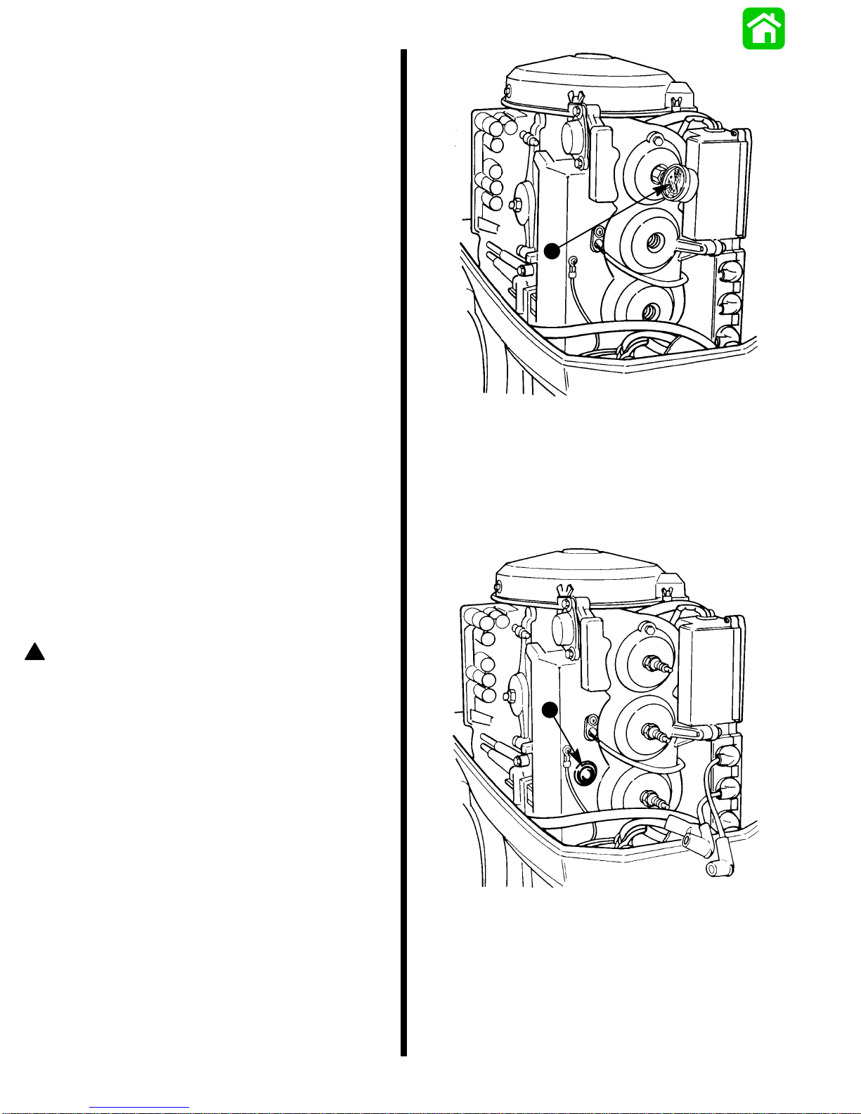
Power Trim System
(Models with Power Trim)
GENERAL INFORMATION
NOTE: 50/60 models are not equipped with Trim System
Design I. See chart below.
Trim System Design II
a
Design I Design II Design IIIModel
40 (4cyl)
50/60
XXX
XX
The power trim system is filled at the manufacturer and is
ready for use.
Trim outboard through entire trailering range several times
to remove any air from the system.
The trim system is pressurized and is not externally vented.
The outboard can be raised or lowered manually by loos-
ening the manual release valve 2 to 3 turns counterclockwise.
The trim “out” angle of this outboard is not adjustable. The
trim system has an internal valve which will automatically
stop the outward trim travel at 20° when engine RPM is approximately 2000 RPM or higher; outboard also has to be
in water and in gear.
The outboard can be operated beyond the 20° trim limit for
operating outboard in shallow water if engine RPM is kept
below approximately 2000 RPM.
b
50158 50146
Trim System Design III
a
52029
a - Fill Screw (System is Pressurized, DO NOT Open Unless Outboard
is Tilted to Full Up Position)
b - Manual Tilt Release Valve Location
a
52028
1-10 - GENERAL INFORMATION and SPECIFICATIONS 90-817643R1 DECEMBER 1996
Page 15
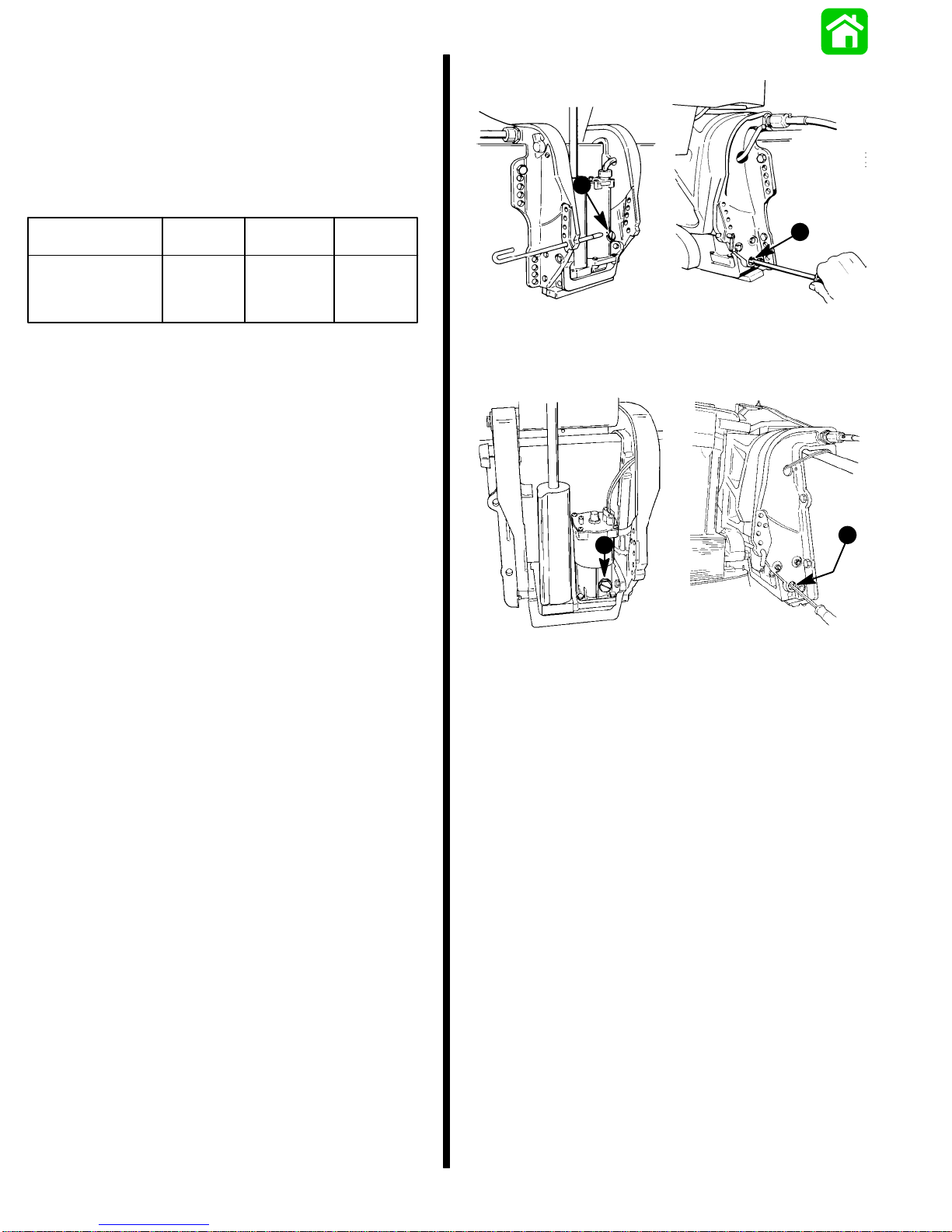
CHECKING TRIM SYSTEM FLUID LEVEL
IMPORT ANT : This trim system is pressurized. Remove
fill screw when outboard is trimmed to the full “up” position. Retighten fill screw securely.
1. Trim outboard to full “up” position. Engage tilt lock lever
(a). Trim system fluid can only be checked when outboard is in this position.
a
TRIMMING OUTBOARD “OUT” (“UP”) CHARACTERISTICS
! WARNING
Excessive trim “out” also may reduce the stability of
some high speed hulls. To correct instability at high
speed, reduce the power GRADUALLY and trim the
outboard “in” slightly before resuming high speed operation. (Rapid reduction in power will cause a sudden
change of steering torque and may cause additional
momentary boat instability.)
1. Will lift bow of boat, generally increasing top speed.
2. Transfers steering torque harder to left on standard or
slightly elevated transom installation (single outboard).
3. Increases clearance over submerged objects.
4. In excess, can cause porpoising and/or ventilation.
5. If trimmed out beyond the water pickup, reduced water
supply can cause serious overheating.
TRIMMING OUTBOARD “IN” (“DOWN”)
CHARACTERISTICS
50157
2. Remove fill screw and check fluid level. Fluid level
should be to bottom of threads in fill hole (b).
3. If necessary, add Quicksilver Power Trim & Steering
Fluid or; Automatic Transmission Fluid (ATF) Type F,
FA or Dexron II fluid to trim system.
4. Reinstall fill screw.
Trimming (Models with Power Trim)
NOTE: Because varying hull designs react differently in
various degrees of rough water, it is recommended to experiment with trim positions to determine whether trimming
up or down will improve the ride in rough water.
When trimming your outboard from a mid-trim position (trim
tab in neutral straight fore-and-aft position), you can expect
the following results:
! WARNING
Excessive speed at minimum trim “in” may cause undesirable and/or unsafe steering conditions. Each
boat should be tested for handling characteristics after any adjustment is made to the trim angle (trim adjustment pin relocation).
1. Will help planing off, particularly with a heavy load.
2. Usually improves ride in choppy water.
3. In excess, can cause boat to veer to the left or right
(bow steer).
4. Transfers steering torque harder to right (or less to the
left) on single outboard installations.
5. Improves planing speed acceleration.
GENERAL INFORMATION and SPECIFICATIONS - 1-1190-817643R1 DECEMBER 1996
Page 16
Trim Tab Adjustment
Boat Performance
1. Check trim tab position as follows:
a. Operate boat at the speed at which it would nor-
mally be operated.
b. If the boat pulls to the right (starboard), the trailing
edge of trim tab must be moved to the right. If the
boat pulls to the left (port), the trailing edge of trim
tab must be moved to the left.
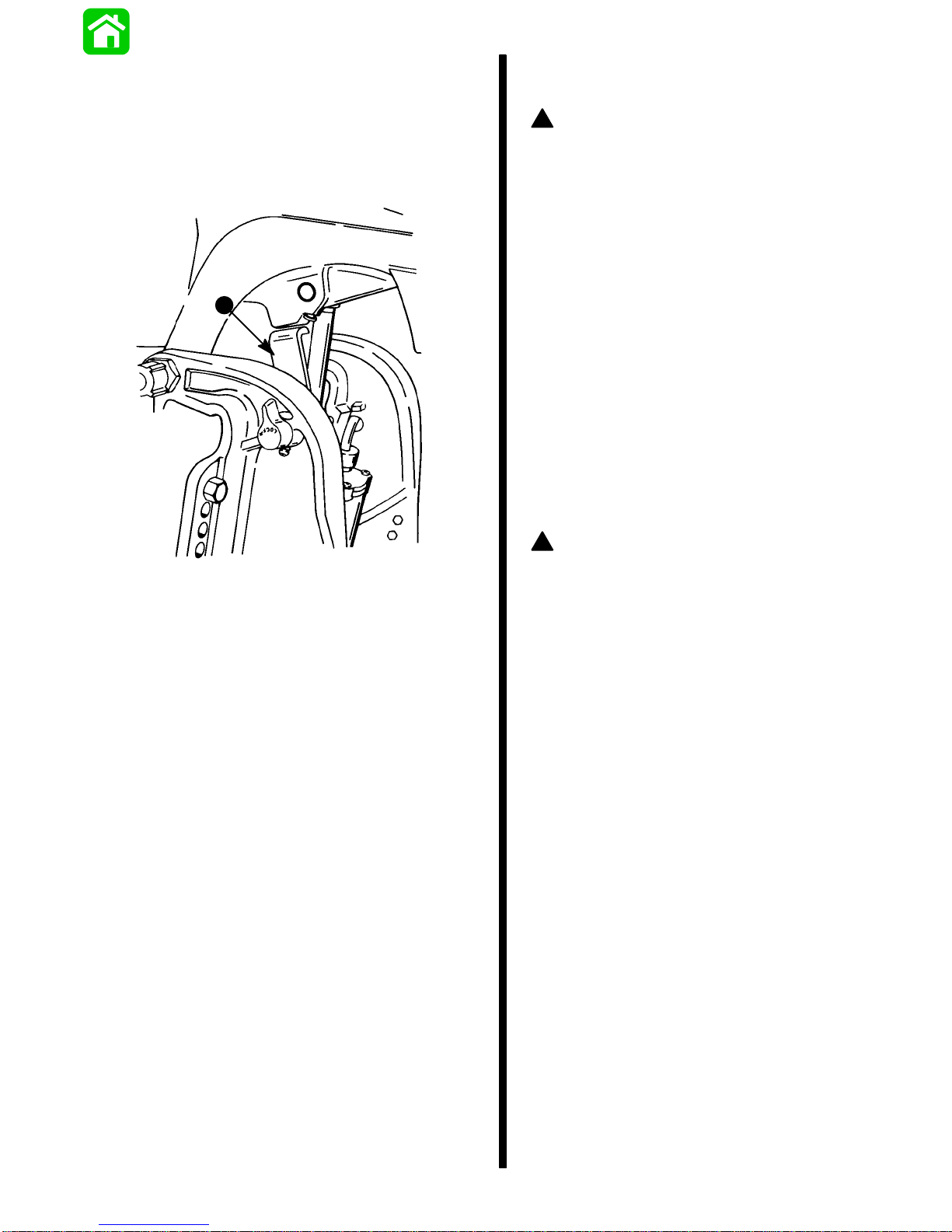
2. If necessary, adjust trim tab as follows:
a. Shift outboard control into neutral and turn ignition
key to “Off” position.
b. Loosen bolt (c) and trim tab (b).
c. If boat pulls to the left, adjust trailing edge of trim
tab to the left. If boat pulls to the right, adjust trailing
edge of trim tab to the right.
d. Tighten trim tab bolt securely.
e. Operate boat per “Check trim tab position as
follows,” to check trim tab setting. If necessary
readjust trim tab.
a
TEST INSTRUCTIONS
! WARNING
A tight grip on the steering wheel/tiller handle is
always advisable and is required when accelerating,
decelerating or when trimming the boat. On models
with Power Trim, upon reaching cruising speed, the
outboard should be trimmed to obtain a balanced
steering condition. While trimming, steering loads will
vary and will pull in one direction until a balanced
condition has been attained. If the outboard is trimmed
past the balanced steering condition, the steering
wheel/tiller handle then will have a tendency to pull in
the opposite direction. Excessive trimming past the
balanced steering position will result in increased
steering loads and, in most boat applications, a
decrease in performance.
!
CAUTION
When trimming boat with dual outboards, both outboards should be at approximately the same tilt angle
and be tilted out (up) simultaneously (to prevent boat
from veering side-to-side) until desired boat attitude is
achieved. Outboards can then be trimmed individually
to precisely adjust boat trim angle and pitch.
1. With boat in water, trim the outboard(s) (trim button in
remote control handle) so that the decal on the side of
cowl is horizontal. This is a typical average setting that
should give reasonable acceleration and top speed.
b
c
a - Anti-Ventilation Plate
b - Adjustable Trim Tab
c - Bolt
50553
2. Go for a short familiarization ride at various throttle and
trim settings BEFORE starting testing.
NOTE: Instruments should be read with eye directly in front
to eliminate any error in reading the instruments.
3. When making either top speed or acceleration runs,
best accuracy will be obtained by running with or
against any wind. Side winds require driving in a constant turn to keep the boat moving straight-ahead. If
winds are 10 MPH (16 km/hr) or greater, it is suggested
that all acceleration runs be made downwind.
4. The top speed WOT (wide-open-throttle) test should
be done with the boat normally loaded (to duplicate
actual running conditions). Operate boat in gear at
WOT and check RPM. Engine RPM must be within the
recommended full throttle RPM range (listed in the
Operation and Maintenance Manual).
NOTE: When performing an acceleration test, it is
recommended that a stop watch be used to improve testing
accuracy. A wrist watch with a second hand may also be
substituted.
1-12 - GENERAL INFORMATION and SPECIFICATIONS 90-817643R1 DECEMBER 1996
Page 17
BOAT TEST CHART (Example)
Propeller
Diameter
and
Pitch
101/8” x
15
1
10
/4” x
WOT
WOT
MPH
RPM
*
5450
57003534
Acceleration
in Seconds
*
Time
7
6
Propeller Break Loose Wind during Run
During
Acceleration
slight
no
During
Turns
no
no
*WOT is wide-open-throttle
5. An acceleration test can also be performed if desired.
Start the test with boat motionless in the water and outboard in neutral. A stop watch should be started as the
throttle is quickly pushed to WOT (wide-open-throttle).
Stop the watch as the speedometer needle sweeps
past 20 MPH (32 km/hr). Several runs should be made
to assure a good average.
6. Prop “break loose” (sudden higher RPM), if not excessive, in some cases can be beneficial during acceleration. If undesirable “break loose” occurs, it can be decreased by trimming the outboard further under. If it
remains excessive with all similar propellers, the outboard must be lowered.
Direction
Air
Temperature
(
°F)
73
73
Comments
MPH
5
5
Water
Condition
3”
chop
7. It is suggested that all applicable data be recorded on
a chart (such as that illustrated, above) and retained
for future reference.
8. After several propellers of different pitch and/or design
have been tried, select one that best serves the general purpose of the boat. The selected propeller should
enable the engine to operate within its recommended
full throttle RPM range, without excessive propeller
“break loose” during acceleration or turns. A second
propeller that would make both a suitable spare or a
special purpose alternate might also be desirable.
NOTE: A higher pitch often gives best top speed, but the
next lower pitch gives adequate top speed with much better
acceleration.
GENERAL INFORMATION and SPECIFICATIONS - 1-1390-817643R1 DECEMBER 1996
Page 18
Lubrication Points
1
1
1
Item
No.
1
2
3
4
5
6
7
8
9
*
Description
Throttle/Shift
Linkage
Pivot Points
Upper
Shift
Shaft
Swivel Pin
Ride Guide
Steering
Cable
Tilt Tube
Steering
Link Rod
Pivot Points
Propeller
Shaft
Starter Motor
Pinion Gear
Gear
Housing
Bearing
Carrier
Type of
Lubricant
Quicksilver
2-4-C w/Te-
flon
Marine
Lubricant
SAE 30W
Motor Oil
Quicksilver
-Anti-Corrosion Grease
SAE 30W
Motor Oil
Quicksilver
2-4-C w/Te-
flon
Marine
Lubricant
Fresh Water
Frequency
Every
60 Days
Every
60 Days
Once in
Season
Once in
Season
Salt Water
Frequency
Every
30 Days
Every
30 Days
Every
60 Days
Every
60 Days
After first 20
Hours, then
once in
season
1
1
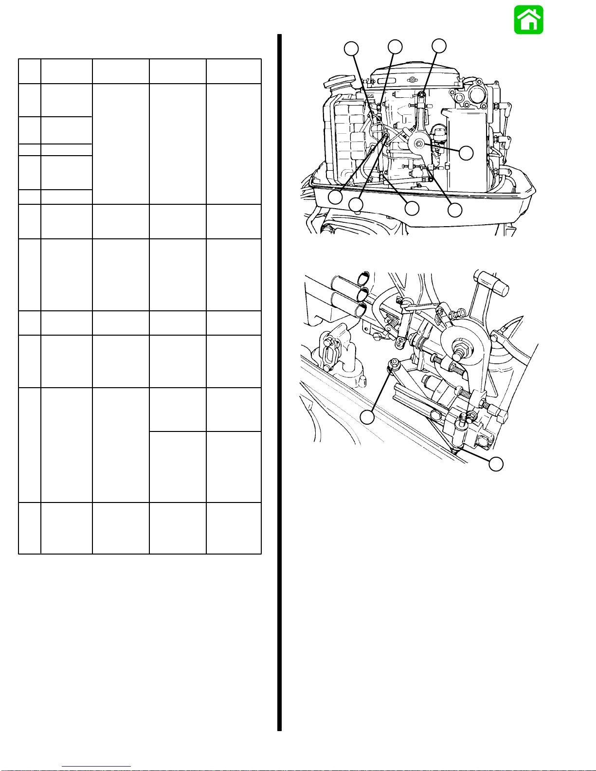
1 - Throttle/Shift Linkage Pivot Point Lubrication
1
1
1
50554
Check and fill
after first 10
days, then
every 30 days
10
Gear
Housing
◊
Engine
Crankshaft
Splines to
∆
Drive Shaft
Splines
* Refer to lubrication instructions outlined in “Salt Water Corrosion -
Gear Housing Bearing Carrier and Cover Nut” of this section (see
“Table of Contents”).
Quicksilver
Gear Lube
Quicksilver
2-4-C w/Te-
flon
Marine
Lubricant
Drain and re-
fill after 1st 25
hours, then
after every
100 hours, or
once a year
before storing
Once in
Season
Check and fill
after first 10
days, then
every 30 days
Drain and re-
fill after 1st 25
hours, then
after every
100 hours, or
once a year
before storing
Once in
Season
◊ Refer to “Gear Housing Lubrication” of this section (see “Table of
Contents”).
∆ Refer to “Gear Housing Removal and Installation” (Section 5).
2
2 - Upper Shift Shaft Lubrication
2
51122
1-14 - GENERAL INFORMATION and SPECIFICATIONS 90-817643R1 DECEMBER 1996
Page 19
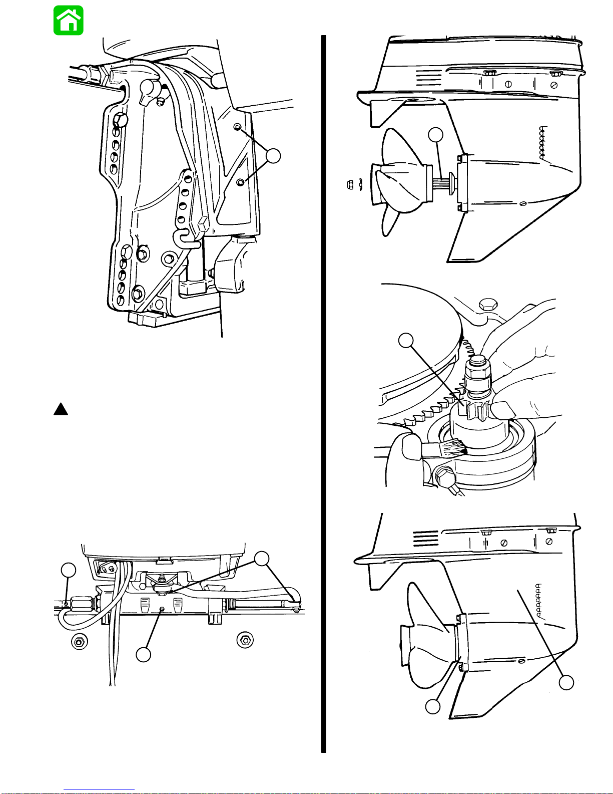
7
3
50551
7 - Propeller Shaft Lubrication (a)
50157
3 - Swivel Pin Grease Fittings
RIDE GUIDE STEERING CABLE and PIVOT POINTS
LUBRICATION
! WARNING
Core of steering cable (transom end) must be fully
retracted into cable housing before lubricating cable.
If cable is lubricated while extended, hydraulic lock of
cable could occur.
With core of Ride Guide Steering cable (transom end) fully
retracted, lubricate transom end of steering cable thru
grease fitting and exposed portion of cable end with Quicksilver 2-4-C Marine Lubricant. Lubricate all pivot points with
SAE 30W engine oil.
6
4
8
51118
8 - Rotate Starter Motor Pinion Gear To Expose Shaft and Lubricate
5
4 - Ride Guide Steering Grease Fitting
5 - Tilt Tube Grease Fitting
6 - Steering Link Rod Pivot Point Lubrication
50334
Gear Housing Lubrication
GENERAL INFORMATION and SPECIFICATIONS - 1-1590-817643R1 DECEMBER 1996
10
9
50558
Page 20
GEAR HOUSING LUBRICATION
NOTE: Refer to “Specifications,” for gear housing lubricant
capacity .
! WARNING
If gear housing is installed on outboard, to avoid accidental starting, disconnect (and isolate) spark plug
leads from spark plugs before working near the propeller.
5. Note color of gear lubricant. White or cream color indicates presence of water in lubricant. Gear lubricant
which has been drained from a gear housing recently
in operation will have a yellowish color due to lubricant
agitation/aeration. This is normal and should not be
confused with the presence of water.
6. Presence of water in gear lubricant indicates the need
for disassembly and inspection of oil seals, seal surfaces, O-rings, water pump gaskets as well as gear
housing components for damage.
!
CAUTION
Do not use automotive grease in the gear housing. Use
only Quicksilver Gear Lube or Quicksilver Super-Duty
Lower Unit Lubricant.
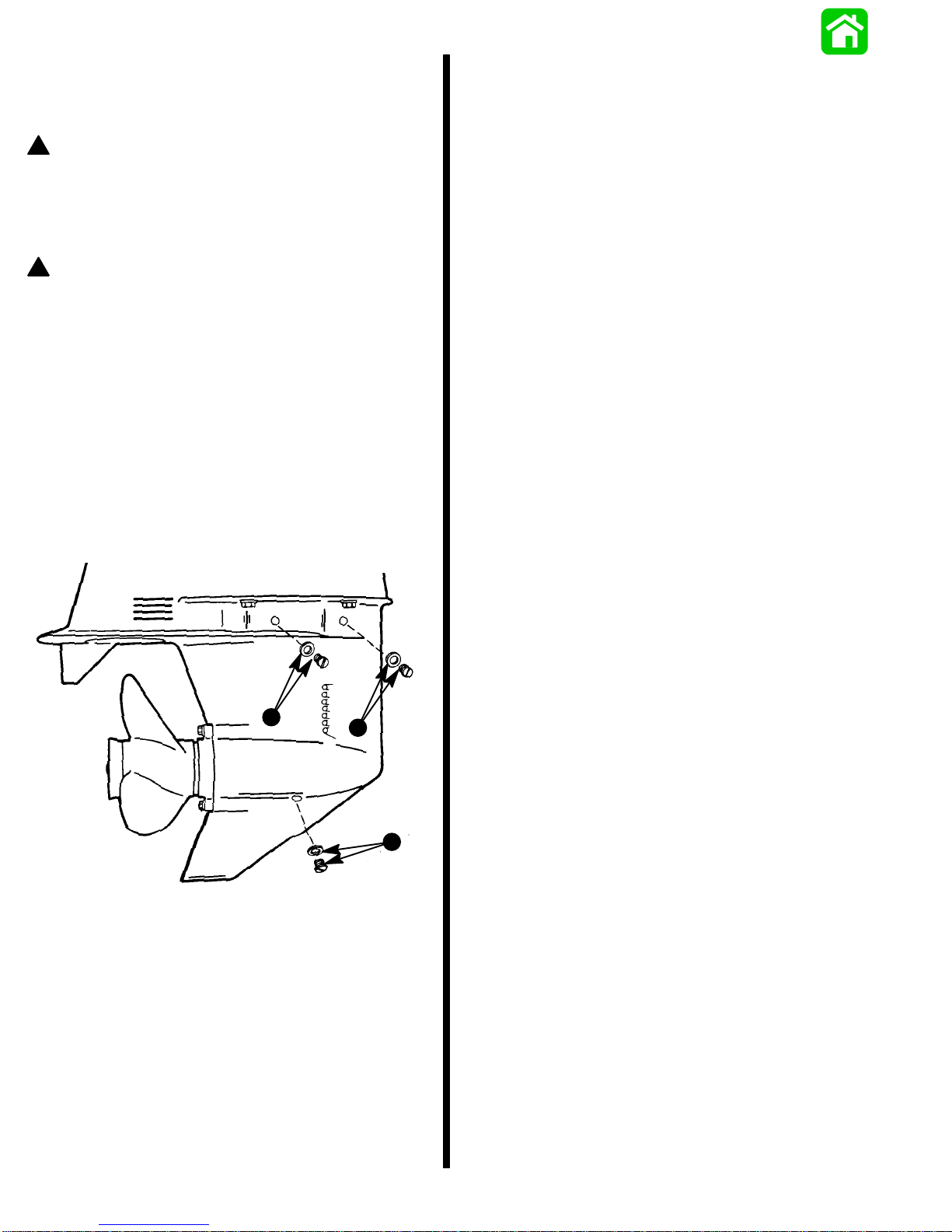
1. Tilt outboard so that lubricant in gear housing will drain
toward front of housing, out fill hole and into clean container.
IMPORT ANT: Inspect FILL and VENT plug washers for
damage. Use new washer as needed.
2. Remove lubricant fill plug and washer. Note amount of
metal particles on magnetic fill plug.
3. Remove VENT plugs and washers (a and c) and allow
all lubricant to drain.
c
a
b
IMPORTANT: Never add lubricant to gear housing
without first removing VENT plugs, as trapped air will
prevent housing from being filled. Fill gear housing
only when outboard is in operating position.
7. With outboard in operating position, insert lubricant
tube into fill hole.
8. Fill gear housing until excess lubricant flows from forward VENT hole.
9. Install VENT plug and washer (a).
10. Continue to fill gear housing until lubricant flows from
VENT hole.
11. Install VENT plug and washer (c).
12. Clean magnet on FILL plug and install FILL plug and
washer (b).
SALT WATER CORROSION - GEAR HOUSING
BEARING CARRIER and COVER NUT
Salt water corrosion buildup can be sufficient to split a gear
housing and destroy an entire lower unit. T o protect against
such damage, therefore, it is recommended that the gear
housing bearing carrier be lubricated on a regular basis, as
follows:
Service first at the 20-hour inspection, then on an annual
basis. Remove the entire bearing carrier to adequately
clean corrosive deposits and dried-up lubricant from both
ends of the bearing carrier, as well as the gear housing.
Apply a liberal amount of 2-4-C w/Teflon Marine Lubricant
to the 2 ends of the bearing carrier, then reassemble and
torque to specifications. Refer to gear housing disassembly and reassembly (Section 6A).
50558
a - Lubricant VENT Plug/Washer
b - Lubricant Fill Plug/Washer
c - Lubricant VENT Plug/Washer
4. Inspect gear lubricant for metal particles (lubricant will
have a “metal flake” appearance). Presence of fine
metal particles (resembling powder) on the FILL plug
bar magnet indicates normal wear. The presence of
metal chips on the drain plug bar magnet indicates the
need for gear housing disassembly and components
inspection.
1-16 - GENERAL INFORMATION and SPECIFICATIONS 90-817643R1 DECEMBER 1996
Page 21
Periodic Inspection
Flushing Outboard Cooling System
Conduct a periodic, systematic inspection to uncover and
correct a failure before it can cause inconvenience or mechanical damage. Inspection interval is based on average
operating conditions in recreation service. Under severe
conditions, the inspection interval should be shortened. Inspection includes:
1. Clean entire unit thoroughly, including all accessible
powerhead parts.
2. Check entire unit for loose, damaged or missing parts.
Tighten or replace as required.
3. Lubricate gear housing.
4. Lubricate other points as indicated, previously.
5. Lubricate starter motor shaft with light film of SAE 10W
motor oil. Do not over-lubricate.
6. Service spark plugs. Inspect spark plug leads and
electrical leads for damage or deterioration, as explained in Section 2 “Electrical and Ignition”.
7. Inspect fuel lines for damage or deterioration and service fuel filters as indicated in Section 3 “Fuel System
and Carburetion.”
8. Remove propeller and inspect. Trim nicks and burrs
with a file, being careful not to remove more metal than
absolutely necessary. Inspect for cracks, damage or
bent condition. If condition is doubtful, refer to authorized Quicksilver Propeller Repair Station facilities.
Before reinstalling propeller, coat propeller shaft with
Quicksilver Special Lubricant 101, Anti-Corrosion
Grease or 2-4-C w/Teflon Marine Lubricant.
9. Inspect the outboard surface finish for damage or
corrosion. Thoroughly clean damaged or corroded
areas and apply matching paint (Quicksilver Spray
Paints).
10. Check trim tab and galvanic corrosion sacrificial anode
for damage or for deterioration from salt water
operation.
11. Check remote controls and steering. Be sure that all
connections and fittings are in good condition, properly
secured and correctly adjusted.
! WARNING
When flushing, be certain that area in vicinity of propeller is clear and that no person is standing nearby –
to avoid possible injury . It is recommended to remove
propeller as a precautionary measure.
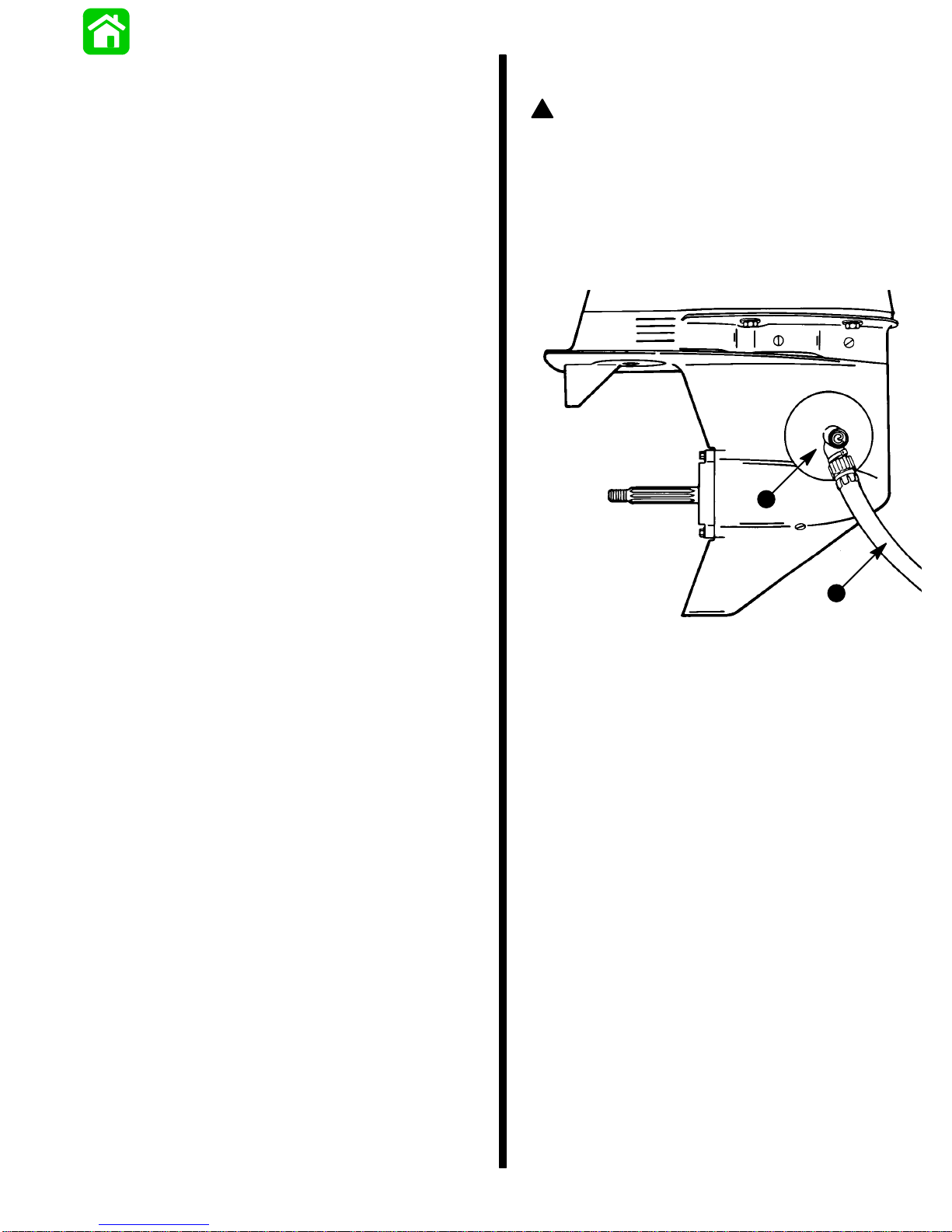
1. Install Quicksilver Flushing Attachment (73971A2) [or
equivalent tool] on the gear housing from the FRONT
side, positioning the rubber cups over the water intake
openings.
b
a
50551
a - Water Hose (1/2 in. [13mm] I.D. or Larger)
b - Flushing Attachment (73971A2)
(Typical Gear Housing)
2. Connect hose (1/2 in. [13mm] I.D. or larger) between
flushing attachment and water tap.
IMPORTANT: To prevent water pump damage, do not
start or run engine unless cooling water is flowing.
3. With the outboard in normal operating position (vertical), partially open water tap (IT MA Y NOT BE NECESSARY to use full water pressure) and adjust water flow
so that there is a significant water loss around the rubber cups.
GENERAL INFORMATION and SPECIFICATIONS - 1-1790-817643R1 DECEMBER 1996
Page 22

4. Start engine and idle in neutral. Then increase engine
speed, not to exceed 2500 RPM.
SUBMERGED ENGINE (FRESH WATER)
(PLUS SPECIAL INSTRUCTIONS)
5. Flush or service engine as required. Be sure adequate
cooling water is provided.
a. Water must be discharged thru “tell-tale outlet.”
IMPORT ANT : Prevent engine overheating. If water flow
is insufficient, stop engine and determine cause before continuing.
b. Flush until discharged water is clear. In saltwater
areas, run outboard 3 to 5 minutes.
c. Stop engine before turning off water.
6. Stop engine, turn water off and remove flushing attachment from gear housing.
IMPORTANT: While and after flushing, keep outboard
in upright position until all water has drained from
drive shaft housing to prevent water from entering the
powerhead via drive shaft housing and exhaust ports.
Following Complete Submersion
Submerged engine treatment is divided into 3 distinct
problem areas. The most critical is submersion in salt
water; the second is submersion while running.
SAL T WATER SUBMERSION (SPECIAL
INSTRUCTIONS)
Due to the corrosive effect of salt water on internal engine
components, complete disassembly is necessary before
any attempt is made to start the engine.
1. Recover engine as quickly as possible.
2. Remove cowling.
3. Flush exterior of outboard with fresh water to remove
mud, weeds, etc. DO NOT attempt to start engine if
sand has entered powerhead, as powerhead will be
severely damaged. Disassemble powerhead if necessary to clean components.
4. Remove spark plugs and get as much water as possible out of powerhead. Most water can be eliminated by
placing engine in a horizontal position (with spark plug
holes down) and rotating flywheel.
5. Pour alcohol into carburetor throat (alcohol will absorb
water). Again rotate flywheel.
6. Turn engine over and pour alcohol into spark plug
openings and again rotate flywheel.
7. Turn engine over (place spark plug openings down)
and pour engine oil into throats of carburetors while
rotating flywheel to distribute oil throughout crankcase.
8. Again turn engine over and pour approximately one
teaspoon of engine oil into each spark plug opening.
Again rotate flywheel to distribute oil in cylinders.
9. Remove and clean carburetors and fuel pump assembly .
10. Reinstall spark plugs, carburetors and fuel pump.
11. Attempt to start engine, using a fresh fuel source. If
engine starts, it should be run for at least one hour to
eliminate any water in engine.
SUBMERGED WHILE RUNNING (SPECIAL
INSTRUCTIONS)
When an engine is submerged while running, the possibility of internal engine damage is greatly increased. If, after
engine is recovered and with spark plugs removed, engine
fails to rotate freely when turning flywheel, the possibility of
internal damage (bent connecting rod and/or bent crankshaft) exists. If this is the case, the powerhead must be
disassembled.
12. If engine fails to start, determine cause (fuel, electrical
or mechanical). Engine should be run within 2 hours
after recovery of outboard from water, as serious internal damage may occur. If unable to start engine in this
period, disassemble engine and clean all parts and
apply oil as soon as possible.
1-18 - GENERAL INFORMATION and SPECIFICATIONS 90-817643R1 DECEMBER 1996
Page 23

Out-of-Season Outboard Storage
! WARNING
As a safety precaution, when boat is in storage,
remove positive (+) battery cable. This will eliminate
possibility of accidental starting of engine and resultant overheating and damage to engine from lack of
water.
In preparing an outboard for out-of-season storage, 2 precautions must be considered: 1) The engine must be protected from physical damage and 2) the engine must be
protected from rust, corrosion and dirt.
1. Remove cowling from engine.
2. Place outboard in water or install Quicksilver Flushing
Attachment over water intake by following instructions
outlined in “Flushing Cooling System” (see “Table of
Contents”).
3. Start engine and allow to warm up. Disconnect fuel
line. When engine starts to stall quickly spray Quicksilver Storage Seal into each carburetor throat. Continue
to spray until engine dies from lack of fuel.
4. Remove spark plugs and inject a 5 second spray of
Quicksilver Storage Seal around the inside of each cylinder. Manually turn engine over several times to distribute Storage Seal throughout cylinders. Reinstall
spark plugs.
5. If engine fuel filter appears to be contaminated, remove and replace. Refer to Section 3 “Fuel System
and Carburetion.”
6. Drain and refill lower unit with Quicksilver Gear Lube,
as explained in “Gear Housing Lubrication” (see “T able
of Contents”).
7. Clean outboard thoroughly, including all accessible
powerhead parts, and spray with Corrosion and Rust
Preventive.
8. Refer to lubrication chart in this section (see “Table of
Contents”) and lubricate all lubrication points.
9. Remove propeller. Apply Quicksilver Special Lubricant
101, Anti-Corrosion Grease or 2-4-C w/Teflon Marine
Lubricant to propeller shaft and reinstall propeller.
Refer to “Propeller Installation” (see “Table of
Contents”).
10. If the water pickup is clogged, the speedometer will be
inoperative. Clean the pickup with a piece of wire or
blow out with compressed air. Before blowing out with
air, disconnect the tubing from the speedometer.
11. To prevent freeze damage, drain the speedometer
system of water completely before storage. Remove
tubing from speedometer fitting and blow thru the
tubing to remove water.
12. Store battery as outlined in “Out-of-Season Battery
Storage,” following.
13. For out-of-season storage information on Autoblend
units, refer to Section 8 in this service manual.
IMPORT ANT: When storing outboard for the winter, be
sure that all water drain holes in gear housing are open
and free so that all water will drain out. If a speedometer is installed in the boat, disconnect the pickup tube
and allow it to drain. Reconnect the tube after draining.
Trapped water may freeze and expand, thus cracking
gear housing and/or water pump housing. Check and
refill gear housing with Quicksilver Gear Lube before
storage to protect against possible water leakage into
gear housing which is caused by loose lubricant vent
plug or loose grease fill plug. Inspect gaskets under
lubricant vent and fill plugs, replacing any damaged
gaskets, before reinstalling plugs.
Out-of-Season Battery Storage
1. Remove battery as soon as possible and remove all
grease, sulfate and dirt from top surface.
2. Cover PLA TES with distilled water, but not over 3/16 in.
(5mm) above perforated baffles.
3. Cover terminal bolts well with grease.
4. Store battery in a COOL, DRY place in a dry carton or
box.
5. Remove battery from storage every 60 days. Check
water level and place on charge for 5 to 6 hours at 6
amperes. DO NOT fast charge.
!
CAUTION
A discharged battery can be damaged by freezing.
GENERAL INFORMATION and SPECIFICATIONS - 1-1990-817643R1 DECEMBER 1996
Page 24
How Weather Affects Engine
Performance
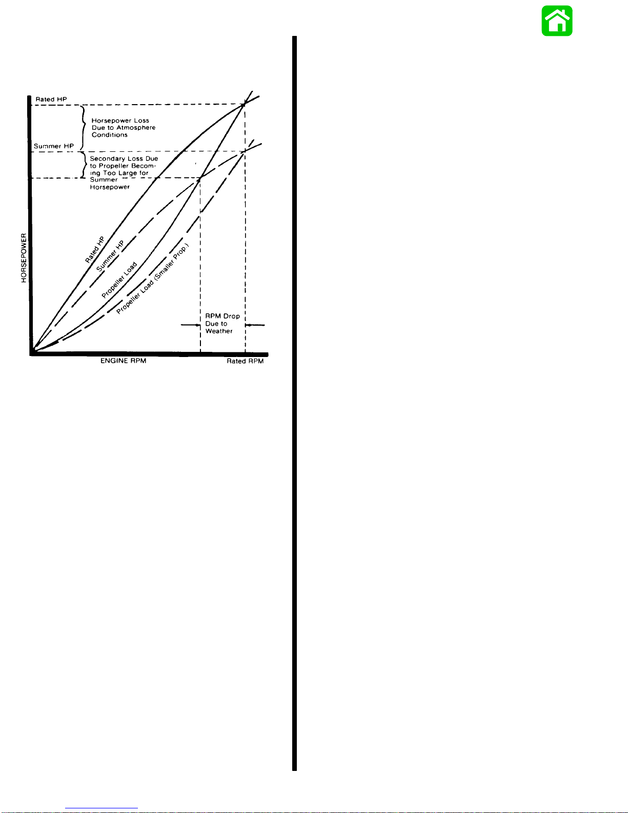
Summer Conditions of high temperature, low barometric
pressure and high humidity all combine to reduce the
engine power. This, in turn, is reflected in decreased boat
speeds--as much as 2 or 3 miles-per-hour (3 or 5 Km
per-hour) in some cases. (Refer to previous chart.) Nothing
will regain this speed for the boater, but the coming of cool,
dry weather.
In pointing out the practical consequences of weather
effects, an engine--running on a hot, humid summer
day--may encounter a loss of as much as 14% of the
horsepower it would produce on a dry, brisk spring or fall
day . The horsepower , that any internal combustion engine
produces, depends upon the density of the air that it
consumes and, in turn, this density is dependent upon the
temperature of the air, its barometric pressure and water
vapor (or humidity) content.
Accompanying this weather-inspired loss of power is a
second but more subtle loss. At rigging time in early spring,
the engine was equipped with a propeller that allowed the
engine to turn within its recommended RPM range at full
throttle. With the coming of the summer weather and the
consequent drop in available horsepower, this propeller
will, in effect, become too large. Consequently , the engine
operates at less than its recommended RPM.
It is a known fact that weather conditions exert a profound
effect on power output of internal combustion engines.
Therefore, established horsepower ratings refer to the
power that the engine will produce at its rated RPM under
a specific combination of weather conditions.
Corporations internationally have settled on adoption of
I.S.O. (International Standards Organization) engine test
standards, as set forth in I.S.O. 3046 standardizing the
computation of horsepower from data obtained on the dynamometer, correcting all values to the power that the engine will produce at sea level, at 30% relative humidity at
77° F (25° C) temperature and a barometric pressure of
29.61 inches of mercury.
Due to the horsepower/RPM characteristics of an engine,
this will result in further loss of horsepower at the propeller
with another decrease in boat speed. This secondary loss,
however, can be regained by switching to a smaller pitch
propeller that allows the engine to again run at recommended RPM.
For boaters to realize optimum engine performance under
changing weather conditions, it is essential that the engine
have the proper propeller to allow it to operate at or near
the top end of the recommended maximum RPM range at
wide-open-throttle with a normal boat load.
Not only does this allow the engine to develop full power,
but equally important is the fact that the engine also will be
operating in an RPM range that discourages damaging
detonation. This, of course, enhances overall reliability and
durability of the engine.
1-20 - GENERAL INFORMATION and SPECIFICATIONS 90-817643R1 DECEMBER 1996
Page 25
Conditions Affecting Operation
1. Proper positioning of the weight inside the boat (persons and gear) has a significant effect on the boat’s
performance, for example:
a. Shifting weight to the rear (stern)
(1) Generally increases top speed.
(2) If in excess, can cause the boat to porpoise.
(3) Can make the bow bounce excessively in
choppy water.
(4) Will increase the danger of the following -
wave splashing into the boat when coming off
plane.
b. Shifting weight to the front (bow)
(1) Improves ease of planing off.
(2) Generally improves rough water ride.
(3) If excessive, can make the boat veer left and
right (bow steer).
2. Boat Bottom: For maximum speed, a boat bottom
should be nearly a flat plane where it contacts the
water and particularly straight and smooth in fore-andaft direction.
a. Hook: Exists when bottom is concave in fore-and-
aft direction when viewed from the side. When
boat is planing, “hook” causes more lift on bottom
near transom and allows bow to drop, thus greatly
increasing wetted surface and reducing boat
speed. “Hook” frequently is caused by supporting
boat too far ahead of transom while hauling on a
trailer or during storage.
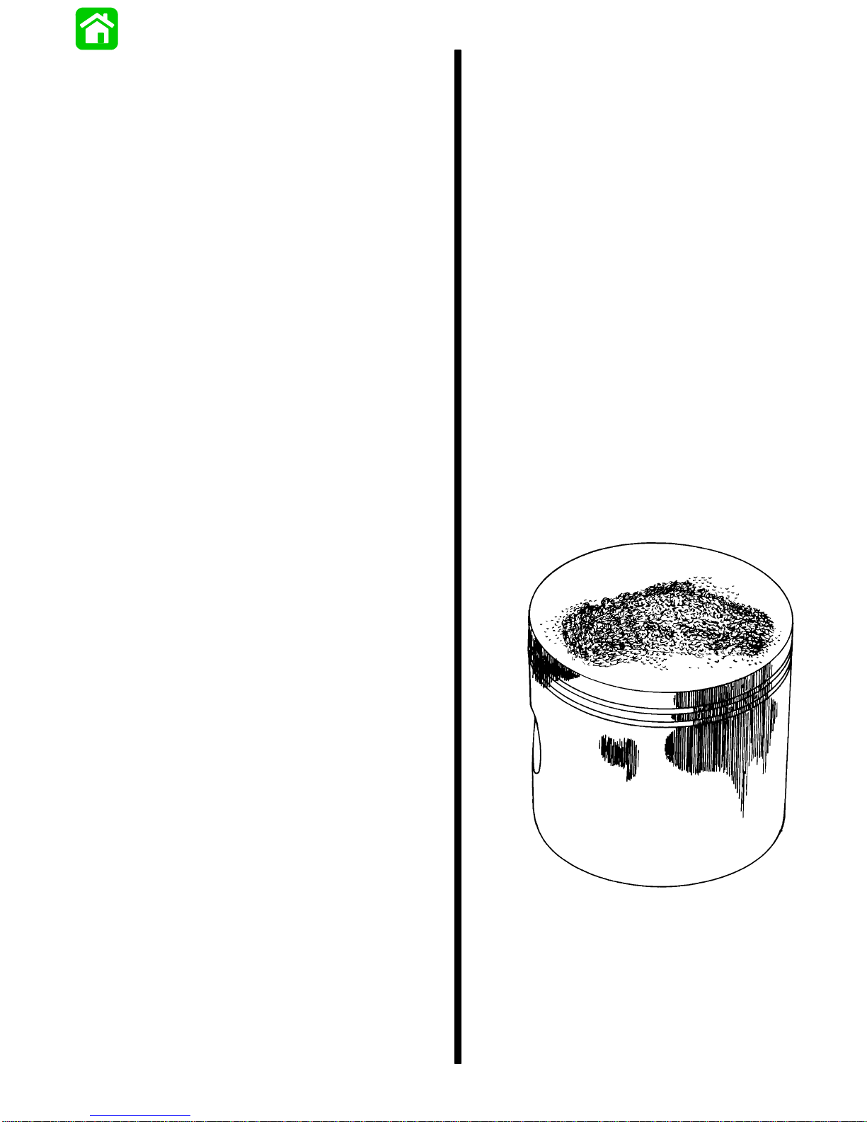
Detonation generally is thought of as spontaneous ignition,
but it is best described as a noisy explosion in an unburned
portion of the fuel/air charge after the spark plug has fired.
Detonation creates severe, untimely, shock waves in the
engine, and these shock waves often find or create a weakness: The dome of a piston, piston rings or piston ring
lands, piston pin and roller bearings.
While there are many causes for detonation in a 2-cycle
engine, emphasis is placed on those causes which are
most common in marine 2-cycle application. A few, which
are not commonly understood, are:
1. Over-advanced ignition timing.
2. Use of low octane gasoline.
3. Propeller pitch too high (engine RPM below recommended maximum range).
4. Lean fuel mixture at or near wide-open-throttle.
5. Spark plugs (heat range too hot - incorrect reach
- cross-firing).
6. Inadequate engine cooling (deteriorated cooling
system).
7. Combustion chamber/piston deposits (result in
higher compression ratio).
Detonation usually can be prevented, provided that 1) the
engine is correctly set up and 2) diligent maintenance is
applied to combat the detonation causes, listed, preceding.
b. Rocker: The reverse of hook and much less com-
mon. “Rocker” exists if bottom is convex in foreand-aft direction when viewed from the side, and
boat has strong tendency to porpoise.
c. Surface Roughness: Moss, barnacles, etc., on
boat or corrosion of outboard’s gear housing increase skin friction and cause speed loss. Clean
surfaces when necessary.
3. Gear Housing: If unit is left in the water , marine vegetation may accumulate over a period of time in certain
types of water. This growth must be removed from unit
before operation, as it may clog the water inlet holes in
the gear housing and cause the engine to overheat.
Detonation: Causes and Prevention
Detonation in a 2-cycle engine somewhat resembles the
“pinging” heard in an automobile engine. It can be otherwise described as a tin-link “rattling” or “pinging” sound.
511 15
Damaged Piston Resulting from Detonation
Compression Check
1. Remove spark plugs.
2. Install compression gauge (a) in spark plug hole.
3. Hold throttle plates at W.O.T.
GENERAL INFORMATION and SPECIFICATIONS - 1-2190-817643R1 DECEMBER 1996
Page 26
4. Crank engine thru at least 4 compression strokes to
obtain highest possible reading.
5. Check and record compression of each cylinder.
Variation of more than 15 psi. (103.5 kPa) between
cylinders indicates that lower compression cylinder is
in some way defective, such as worn or sticking piston
rings and/or scored piston and cylinder.
6. Compression check is important because an engine
with low or uneven compression cannot be tuned
successfully to give peak performance. It is essential,
therefore, that improper compression be corrected
before proceeding with an engine tuneup.
7. Cylinder scoring: If powerhead shows any indication of
overheating, such as discolored or scorched paint,
visually inspect cylinders for scoring or other damage
as outlined in Section 4 “Powerhead.”
Water Pressure Check
NOTE: T o perform these checks, a Water Pressure Gauge
Kit, P/N 91-79250A2 is recommended.
1. Water pressure at idle, in neutral, is 1-3 psi (7-21 kPa).
2. Water pressure should increase, then drop to 4-6 psi
(21-35 kPa) prior to 2500 RPM (due to poppet valve
opening.)
3. At 2500 RPM, water pressure should not exceed 12 psi
(83 kPa). Readings above 12 psi at 2500 RPM may indicate a stuck poppet valve.
a
51046
a - Compression Gauge (P/N 91-29287)
Serial Number Location
The engine serial number is located on the starboard side
of the swivel bracket (as on all Mariner/Mercury models)
and also on the cylinder head (a).
4. Static test (boat stationary - operate in forward gear
with a cut down “ smaller diameter” propeller) at 5000
RPM or above is 7-12 psi (48-83 kPa).
!
CAUTION
A MODIFIED PROPELLER OR LOW PITCH PROPELLER IS REQUIRED TO PERFORM THE ABOVE ST ATIC
TEST. STATIC TEST REQUIRES THE BOAT BE STATIONARY IN THE WATER SECURED TO A DOCK OR
TRAILER AND RUN IN FORW ARD GEAR. DO NOT USE
A FLUSHING DEVICE FOR THIS TEST.
a
51139
1-22 - GENERAL INFORMATION and SPECIFICATIONS 90-817643R1 DECEMBER 1996
Page 27

Painting Procedures
3. Sand blistered area with 3M 180 grit sandpaper
or P180 Gold Film Disc to remove paint blisters
only. Feather edge all broken paint edges.
Cleaning & Painting Aluminum
Propellers & Gear Housings
! WARNING
Avoid serious injury from flying debris. A void serious injury from airborne particles. Use eye and
breathing protection with proper ventilation.
PROPELLERS
1. Sand the entire area to be painted with 3M 120
Regalite Polycut or coarse Scotch-Brite, disc or
belts.
2. Feather edges of all broken paint edges. Try not
to sand through the primer.
3. Clean the surface to be painted using PPG
Industries DX330 Wax and Grease Remover or
equivalent (Xylene or M.E.K.).
4. If bare metal has been exposed, use Quicksilver’s Light Gray Primer.
5. Allow a minimum of 1 hour dry time and no more
than 1 week before applying the finish coat.
6. Apply the finish coat using Quicksilver’s EDP
Propeller Black.
GEAR HOUSINGS
The following procedures should be used in refinishing gear housings. This procedure will provide the
most durable paint system available in the field. The
materials recommended are of high quality and
approximate marine requirements. The following
procedure will provide a repaint job that compares
with a properly applied factory paint finish. It is recommended that the listed materials be purchased
from a local Ditzler Automotive Finish Supply Outlet.
The minimum package quantity of each material
shown following is sufficient to refinish several gear
housings.
Procedure:
4. Clean gear housing thoroughly with (DX-330)
wax and grease remover.
5. Spot repair surfaces where bare metal is exposed with (DX-503) alodine treatment.
IMPORTANT: Do not use any type of aerosol
spray paints as the paint will not properly adhere
to the surface nor will the coating be sufficiently
thick to resist future paint blistering.
6. Mix epoxy chromate primer (DP-40) with equal
part catalyst (DP-401) per manufacturers
instructions, allowing proper induction period for
permeation of the epoxy primer and catalyst.
7. Allow a minimum of one hour drying time and no
more than one week before top coating assemblies.
8. Use Ditzler Urethane DU9000 for Mercury Black,
DU34334 for Mariner Grey, and DU35466 for
Force Charcoal, and DU33414M for Sea Ray
White. Catalyze all three colors with Ditzler DU5
catalyst mixed 1:1 ratio. Reduce with solvents
per Ditzler label.
!
CAUTION
Be sure to comply with instructions on the label
for ventilation and respirators. Using a spray gun,
apply one half to one mil even film thickness. Let
dry, flash off for five minutes and apply another
even coat of one half to one mil film thickness.
This urethane paint will dry to the touch in a matter of hours, but will remain sensitive to scratches
and abrasions for a few days.
9. The type of spray gun used will determine the
proper reduction ratio of the paint.
IMPORT ANT: Do not paint sacrificial zinc trim tab
or zinc anode.
10. Cut out a cardboard “plug” for trim tab pocket to
keep paint off of mating surface to maintain good
continuity circuitry between trim tab and gear
housing.
1. Wash gear housing with a muriatic acid base
cleaner to remove any type of marine growth,
and rinse with water, if necessary.
2. Wash gear housing with soap and water, then
rinse.
GENERAL INFORMATION and SPECIFICATIONS - 1-2390-817643R1 DECEMBER 1996
Page 28

Decal Application
Decal Removal
1. Mark decal location before removal to assure
proper alignment of new decal.
2. Carefully soften decal and decal adhesive with a
heat gun or heat blower while removing old decal.
3. Clean decal contact area with a 1:1 mixture of isopropyl alcohol and water.
4. Thoroughly dry decal contact area and check for
a completely cleaned surface.
DECAL APPLICATION
1
1. Mix
/2 ounce (16 ml) of dish washing liquid in one
gallon (4 l) of cool water to use as wetting solution.
NOTE: Leave protective masking, if present, on the face of
decal until final steps of decal installation. This will ensure
that the vinyl decal keeps it’s shape during installation.
2. Place the decal face down on a clean work surface and remove the paper backing from “adhesive side” of decal.
3. Using a spray bottle, flood the entire “adhesive
side” of the decal with the pre-mixed wetting solution.
4. Flood area where the decal will be positioned with
wetting solution.
Instructions for “Wet” Application
NOTE: The following decal installation instructions are pro-
vided for a “Wet” installation. All decals should be applied
wet.
TOOLS REQUIRED
1. Plastic Squeegee*
2. Stick Pin
3. Dish Washing Liquid/Detergent without am-
monia** “Joy” and “Drift” are known to be compatible for this process.
** Automotive Body Filler Squeegee
** Do not use a soap that contains petroleum based
solvents.
SERVICE TIP: Placement of decals using the
“Wet” application will allow time to position decal. Read entire installation instructions on this
technique before proceeding.
TEMPERATURE
5. Position pre-wetted decal on wetted surface and
slide into position.
6. Starting at the center of the decal, “lightly”
squeegee out the air bubbles and wetting solution
with overlapping strokes to the outer edge of the
decal. Continue going over the decal surface until
all wrinkles are gone and adhesive bonds to the
cowl surface.
7. Wipe decal surface with soft paper towel or cloth.
8. Wait 10 - 15 minutes.
9. Starting at one corner, “carefully and slowly” pull
the masking off the decal surface at a 180° angle.
NOTE: T o remove any remaining bubbles, pierce the decal
at one end of the bubble with stick pin and press out the entrapped air or wetting solution with your thumb (moving toward the puncture).
IMPORTANT: Installation of vinyl decals should
not be attempted while in direct sunlight. Air and
surface temperature should be between 60°F
(15°C) and 100°F (38°C) for best application.
SURFACE PREPARATION
IMPORT ANT: Do not use a soap or any petroleum
based solvents to clean application surface.
Clean entire application surface with mild dish washing liquid and water. Rinse surface thoroughly with
clean water.
1-24 - GENERAL INFORMATION and SPECIFICATIONS 90-817643R1 DECEMBER 1996
Page 29
ELECTRICAL and IGNITION
2
A
IGNITION SYSTEM
51123
Page 30

Table of Contents
Description 2A-1. . . . . . . . . . . . . . . . . . . . . . . . . . . . . . . . . . .
Test Procedures 2A-1. . . . . . . . . . . . . . . . . . . . . . . . . . . . . . .
Direct Voltage Adapter (DVA) Tests 2A-1. . . . . . . . . . .
Test Sequence 2A-2. . . . . . . . . . . . . . . . . . . . . . . . . . . . .
Ignition System Test Chart 2A-3. . . . . . . . . . . . . . . . . . .
Stator Test 2A-4. . . . . . . . . . . . . . . . . . . . . . . . . . . . . .
Ignition Coil Test 2A-5. . . . . . . . . . . . . . . . . . . . . . . . .
Trigger Test 2A-5. . . . . . . . . . . . . . . . . . . . . . . . . . . . .
ADI Ignition using a RED Stator with an
Adapter Module 2A-5. . . . . . . . . . . . . . . . . . . . . . . . . . . . . . .
RED Stator with Adaptor and Ignition Coils 2A-6. . . . . . .
RED Stator DVA Test 2A-6. . . . . . . . . . . . . . . . . . . . . . .
Electric Start Engines 2A-6. . . . . . . . . . . . . . . . . . . . . . .
Manual Start Engines 2A-6. . . . . . . . . . . . . . . . . . . . . . .
Troubleshooting Procedures 2A-6. . . . . . . . . . . . . . . . .
Ignition (Key) Switch Test 2A-7. . . . . . . . . . . . . . . . . . . . . . .
Page
Page
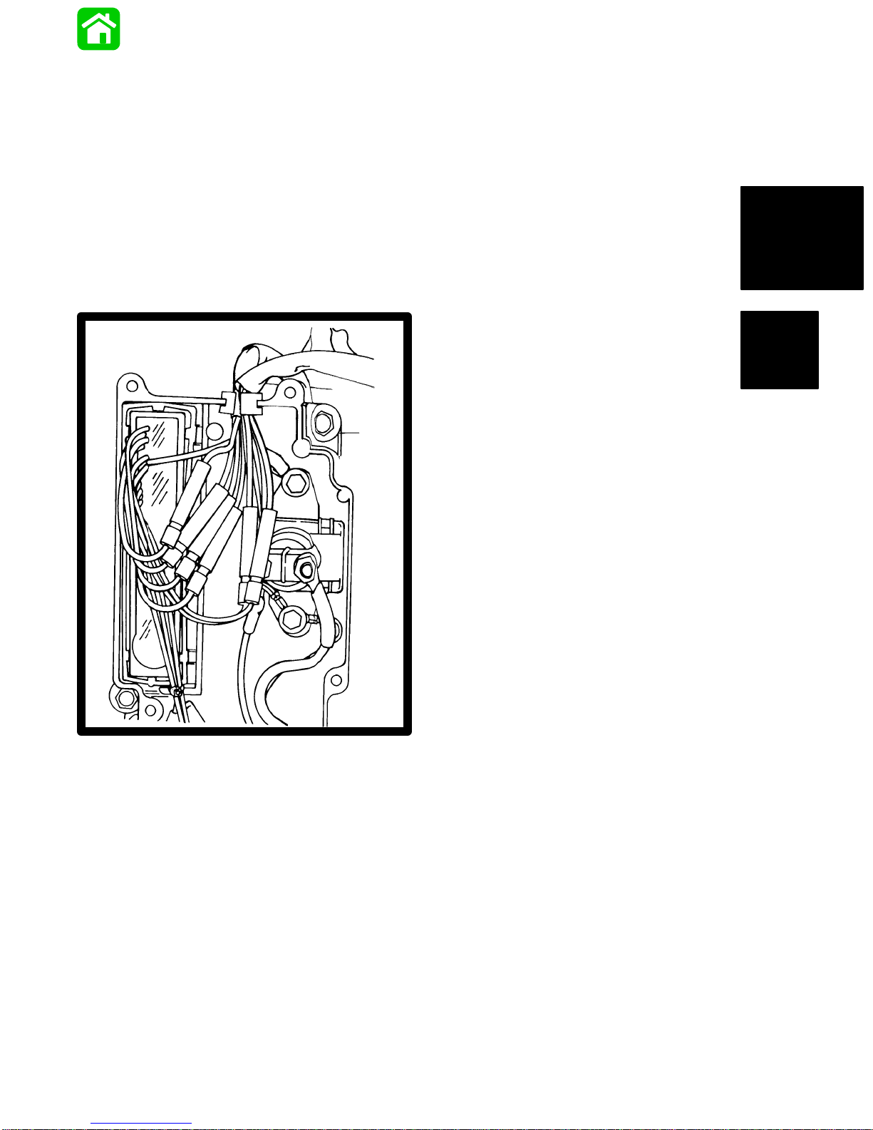
Ignition Components
Removal and Installation 2A-7. . . . . . . . . . . . . . . . . . . . . . .
Flywheel 2A-7. . . . . . . . . . . . . . . . . . . . . . . . . . . . . . . . . .
Removal 2A-7. . . . . . . . . . . . . . . . . . . . . . . . . . . . . . .
Installation 2A-8. . . . . . . . . . . . . . . . . . . . . . . . . . . . . .
BLACK and RED Stator 2A-8. . . . . . . . . . . . . . . . . . . . .
Removal 2A-8. . . . . . . . . . . . . . . . . . . . . . . . . . . . . . .
BLACK Stator Installation 2A-9. . . . . . . . . . . . . . . . .
RED Stator Installation 2A-9. . . . . . . . . . . . . . . . . . .
Trigger 2A-10. . . . . . . . . . . . . . . . . . . . . . . . . . . . . . . . . . .
Removal 2A-10. . . . . . . . . . . . . . . . . . . . . . . . . . . . . .
Installation 2A-10. . . . . . . . . . . . . . . . . . . . . . . . . . . . .
Ignition Coils 2A-11. . . . . . . . . . . . . . . . . . . . . . . . . . . . . .
Switch Box 2A-11. . . . . . . . . . . . . . . . . . . . . . . . . . . . . . .
2A-0 - ELECTRICAL and IGNITION 90-817643R1 DECEMBER 1996
Page 31

Description
Test Procedures
The outboard ignition system is alternator-driven with distributor-less capacitor discharge. Major components of the
ignition system are the flywheel, stator, trigger , switch box,
ignition coils and spark plugs.
The stator assembly is mounted stationary below the flywheel and has 2 capacitor charging coils. The flywheel is
fitted with permanent magnets inside the outer rim. As the
flywheel rotates the permanent magnets pass the capacitor charging coils. This causes the capacitor charging coils
to produce AC voltage. The AC voltage then is conducted
to the switch box where it is rectified and stored in a capacitor.
The trigger assembly (also mounted under the flywheel)
has 3 coils. The flywheel has a second set of permanent
magnets (located around the center hub). As the flywheel
rotates the second set of magnets pass the trigger coils.
This causes the trigger coils to produce an AC voltage that
is conducted to an electric Silicon Controlled Rectifier
(SCR) in the switch box.
The switch discharges the capacitor voltage into the ignition coil at the correct time and firing order sequence.
Capacitor voltage is conducted to the primary side of the
ignition coil. The ignition coil multiplies this voltage high
enough to jump the gap at the spark plug.
The preceding sequence occurs once-per-engine-revolution for each cylinder.
Spark timing is changed (advanced/retarded) by rotating
the trigger assembly which changes each trigger coil position in relation to the permanent magnets on the flywheel
center hub.
IMPORT ANT : If the engine misfires, runs rough or does
not start, the ignition system should be checked using
a Multi-Meter/DVA Tester (91-99750), or a voltmeter
(capable of measuring 400 volts DC, or higher) and Direct Voltage Adaptor (91-89045).
Direct Voltage Adapter (DVA) Tests
! WARNING
DANGER – HIGH VOLTAGE/SHOCK HAZARD! Do not
touch ignition components and/or metal test probes
while engine is running and/or being “cranked”. ST AY
CLEAR OF SP ARK PLUG LEADS. To assure personal
safety, each individual spark plug lead should be
grounded to engine.
!
CAUTION
To protect against meter and/or component damage,
observe the following precautions:
– 400 VDC* test position (or higher) MUST BE used for
all tests.
– INSURE the Positive (+) lead/terminal of DV A is con-
nected to the Positive (+) receptacle of meter
– DO NOT CHANGE meter selector switch position
while engine is running and/or being ”cranked”.
– Switch box MUST BE GROUNDED during tests.
Running or ”cranking” engine with switch box ungrounded may damage switch box.
*If using a meter with a built–in DVA, the DVA/400 VDC test
position should be used.
NOTE: T est leads are not supplied with the DV A. Use test
leads supplied with meter.
T est procedures and specifications are provided for check-
ing primary ignition voltage while the engine is running
and/or being ”cranked”.
TROUBLESHOOTING TIPS:
1. Intermittent, weak, or no spark output at two spark
plugs usually indicates a bad TRIGGER.
2. Intermittent, weak, or no spark output at all three spark
plugs usually indicates a bad STATOR or SWITCH
BOX.
3. Intermittent, weak, or no spark at any one spark plug
usually indicates a bad SPARK PLUG, COIL, or
SWITCH BOX.
ELECTRICAL and IGNITION - 2A-190-817643R1 DECEMBER 1996
Page 32

Test Sequence
1-A) Check primary input voltage to coils (See Test
Chart)
1. If voltage readings to coil(s) are BELOW specification,
proceed with Step 2-A.
2. If voltage readings to coil(s) are WITHIN specifications, proceed with Step 1-B.
1-B) Check coils for spark. [Connect Spark Gap T ester
(91–63998A1) between coil high voltage tower and
spark plug.]
1. No spark or weak spark. COIL is bad.
2. Spark is OK, proceed with Step 1-C.
1-C) If Step 1-A and 1-B check OK, replace spark plugs.
If problem exists after replacing spark plugs, proceed with
Step 1-D.
1-D) If Steps 1-A, 1-B, and 1-C check OK, check igni-
tion timing.
1. If ignition timing does not check to specification (or a
sudden or unexplained timing change occurs) check
trigger advance linkage for loose and/or broken parts
and check trigger magnet ring (on flywheel hub) for
looseness and/or a shift in position.
2. If ignition checks to specification and engine does not
run or runs poorly , trouble exists with fuel system or
engine mechanical.
2-B) Check ignition switch/wiring, as follows:
!
CAUTION
To prevent engine from starting, remove spark plug
leads from ALL spark plugs and ground leads to en-
gine.
1. Disconnect ignition switch and stop switch leads
from switch box and isolate the leads.
2. Repeat check in Step 2-A.
a. If reading is still BELOW specification, proceed
with Step 3-A.
b. If reading is WITHIN specification, either the igni-
tion switch, stop switch, or wiring is bad.
3-A) Check stator low speed and high speed input to
switch box. (see Test Chart).
1. If either the low speed or high speed reading to switch
box is BELOW specification, Stator or Switch Box is
bad (test stator as outlined in this service manual section; if stator checks to specification replace switch box
and repeat check).
2. If both the low speed and high speed reading are
WITHIN specification, replace switch box and repeat
test.
2-A) Check switch box ”stop” circuit. (See T est Chart).
1. If reading is BELOW specifications, proceed with Step
2-B.
2. If reading is ABOVE specifications, the Trigger or
Switch Box is bad (test trigger as outlined in this ser-
vice manual section; if trigger checks OK, replace
switch box and repeat check).
3. If reading is WITHIN specifications, proceed with Step
3-A.
2A-2 - ELECTRICAL and IGNITION 90-817643R1 DECEMBER 1996
Page 33

Ignition System Test Chart
(1)
S
Positi
@300-1000 RPM
@1000-4000 RPM
S
Positi
@300 RPM
@1000 RPM
@4000 RPM
IMPORTANT: BEFORE attempting the ignition system checks, following, thoroughly read the preceding pages of
these instructions to become familiar with the proper Automatic Distributorless Ignition (ADI) test sequence and procedures (particularly any “Safety Warnings” and “Cautions”). ALL tests are performed with lead wires connected –
terminals exposed. SWITCH BOX MUST BE GROUNDED (CASE TO ENGINE BLOCK) FOR ALL TESTS – IF NOT,
SWITCH BOXES MAY BE DAMAGED.
55/60 MARATHON/SEAPRO – (398-9873A-5 printed on the stator)
USA S/N 0G277479 and BELOW
BELGIUM S/N (Not Available at Time of Printing)
45 JET, 50/60 ELECTRIC – (398-9710A22, 398-9710A23, or 398-9710A34 printed on the stator)
USA S/N 0G277605 and BELOW
BELGIUM S/N (Not Available at Time of Printing)
NOTE: When servicing a unit prior to the listed serial number and below, it is recommended that the flywheel be removed and
the stator part number verified to determine proper testing applications.
ADI Test
eq.
1–A Coil Primary 400 VDC* Coil (+)
2–A Switch Box -
3–A
4–A
3–A
4–A
5–A Switch Box -
(1)
Using meter only, REVERSE LEAD POLARITY, connect leads as specified.
Test Selector Sw.
400VDC* Black/Yellow(3)
Stop Circuit
Stator -
400VDC* Blue Sw. Box
Low Speed
Stator -
400VDC* Red Sw. Box Ter-
High Speed
20 VDC or
Bias
on
40 VDC
DVA Leads
Red Black
Terminal
Sw. Box Terminal
Terminal
minal
Ground
(1)
Voltage
Coil (–)
Terminal
Ground 200–360 200–360
Ground 200–300 200–330
Ground 20–90 130–300
White/Black Sw.
Box Terminal
(1)
(*) If using a meter with built-in DVA, place selector switch in the DVA/400 VDC position.
55/60 MARATHON/SEAPRO – (398-9873A21 printed on the stator)
USA S/N 0G277480 and ABOVE
BELGIUM S/N (Not Available at Time of Printing)
45 JET, 50/60 ELECTRIC – (398-9873A24 printed on the stator)
USA S/N 0G277606 and ABOVE
BELGIUM S/N (Not Available at Time of Printing)
Voltage
150–250 180–280
2–10 10–30
ADI Test
Test Selector Sw.
eq.
1–A Coil Primary 400 VDC* Coil (+)
2–A Switch Box -
400VDC* Black/Yellow(3)
Stop Circuit
3–A
4–A
3–A
4–A
5–A Switch Box -
(1)
Using meter only, REVERSE LEAD POLARITY, connect leads as specified.
Stator Low Speed
Stator High Speed
Bias
400VDC* Blue Sw. Box
400VDC* Red Sw. Box
20 VDC or
40 VDC
(*) If using a meter with built-in DVA, place selector switch in the DVA/400 VDC position.
on
DVA Leads
Red Black
Terminal
Sw. Box Termi-
nal
Terminal
Terminal
Ground
(1)
Coil (–)
Voltage
145–175 210–250 200–240
Voltage
Terminal
Ground 215–265 280–340 260–320
Ground 215–265 280–340 260–320
Ground 10–15 45–55 205–255
White/Black Sw.
Box Terminal
(1)
2–10 10–30 10–30
ELECTRICAL and IGNITION - 2A-390-817643R1 DECEMBER 1996
Voltage
Page 34

! WARNING
When testing or servicing the ignition system, high
voltage is present, be extremely cautious! DO NOT
TOUCH OR DISCONNECT any ignition parts while engine is running, while key switch is on, or while battery
cables are connected.
!
CAUTION
Failure to comply with the following items may result
in damage to the ignition system.
1. DO NOT reverse battery cable connections. The
battery negative cable is (-) ground.
2. DO NOT “spark” battery terminals with battery
cable connections to check polarity.
3. DO NOT disconnect battery cables while engine is
running.
4. DO NOT crank engine when switch box is not
grounded to engine.
A process of elimination must be used when checking the
ignition system without a Multi-Meter/DVA Tester
(91-99750) or a voltmeter (capable of measuring 400 volts
DC, or higher) and Direct Voltage Adaptor (91-89045), as
the switch box and ignition coils cannot be thoroughly
checked with conventional test equipment.
55/60 MARATHON/SEAPRO – (398-9873A-5 printed
on the stator)
USA S/N 0G277479 and BELOW
BELGIUM S/N (Not Available at Time of Printing)
45 JET, 50/60 ELECTRIC – (398-9710A22,
398-9710A23, or 398-9710A34 printed on the stator)
USA S/N 0G277605 and BELOW
BELGIUM S/N (Not Available at Time of Printing)
NOTE: When servicing a unit listed “Serial Number and
Below”, it is recommended that the flywheel be removed
and the stator part number verified to determine proper
testing applications.
Test Leads Resistance
(OHMS)
Between Blue
Stator Lead and
Red Stator Lead
(Low Speed)
Between Red
Stator Lead and
Engine Ground*
(Hi-Speed)
*If stator is mounted on engine, black stator lead must be
grounded to powerhead when testing. Connect test lead to
black stator lead if stator is removed from engine.
3600 – 4200
(90 – 140)
90 – 140 90 – 140
Scale Reading
(x_______)
3.6 – 4.2
(R x 1000)
(R x 1)
All other components can be tested with an ohmmeter. Before troubleshooting the ignition system, check the following:
1. Make sure that electrical harness and ignition switch
are not the source of the problem.
2. Check that plug-in connectors are fully engaged and
terminals are free of corrosion.
3. Make sure that wire connections are tight and free of
corrosion.
4. Check all electrical components, that are grounded directly to engine, and all ground wires to see that they
are grounded to engine.
5. Check for disconnected wires, and short and open circuits.
STATOR TEST
NOTE: Stator can be tested without removing from engine.
1. Disconnect stator leads from switch box.
2. Use an ohmmeter and perform the following tests.
IMPORT ANT : If stator is mounted on engine, black stator lead must be grounded to powerhead when testing.
Connect test lead to black stator lead if stator is removed from engine.
55/60 MARATHON/SEAPRO – (398-9873A21 printed
on the stator)
USA S/N 0G277480 and ABOVE
BELGIUM S/N (Not Available at Time of Printing)
45 JET, 50/60 ELECTRIC – (398-9873A24 printed on
the stator)
USA S/N 0G277606 and ABOVE
BELGIUM S/N (Not Available at Time of Printing)
Test Leads
Between Blue
Stator Lead and
Red Stator Lead
(Low Speed)
Between Red
Stator Lead and
Engine Ground*
(Hi-Speed)
*If stator is mounted on engine, black stator lead must be
grounded to powerhead when testing. Connect test lead to
black stator lead if stator is removed from engine.
Resistance
(OHMS)
1100 – 1600 1.1 – 1.6
30 – 35 30 – 35
Scale Reading
(x_______)
(R x 1000)
(R x 1)
NOTE: Readings are for a cold engine (room temperature).
Resistance will increase slightly, if engine is warm.
3. If meter readings are other than specified, replace stator assembly.
2A-4 - ELECTRICAL and IGNITION 90-817643R1 DECEMBER 1996
Page 35

IGNITION COIL TEST
IMPORTANT: Ohmmeter tests can only detect certain
faults in the ignition coil. Replace ignition coil, if ohmmeter readings (listed in chart, following) are not as
specified. If coil tests OK, and coil is still suspected of
being faulty , use Multi-Meter/DVA Tester (91-99750) or
a voltmeter (capable of measuring 400 volts DC, or
higher) and Direct V oltage Adaptor (91-89045) to thoroughly check coil.
1. Disconnect wires from coil terminals.
2. Pull spark plug lead out of coil tower.
3. Use an ohmmeter and perform the following tests.
ADI Ignition using a RED
Stator with an Adapter
Module
Red stators require an adapter module that is connected between the stator and switch box. Without the
adapter module, the voltage supplied by the stator
would exceed the voltage capability of the switch box.
Test Leads
Between (+) and (-) Coil
Terminals
Between Coil Tower and (-)
Coil Terminal
* The primary DC resistance of these coils generally is less than one
(1) OHM. If a reading resembling a short is obtained, this would be
acceptable.
** Copper wire is an excellent conductor, but it will have a noticeable
difference in resistance from cold to hot temperatures. Reasonable
variations from these readings are acceptable.
Resistance
(OHMS)
.02-.04*
800-1 100**
Scale Reading
(x_________)
.02-.04*
(R x 1)
8-11**
(R x 100)
4. If meter readings are not as specified, replace ignition
coil.
TRIGGER TEST
1. Disconnect all trigger leads from switch box.
2. Use an Ohmmeter and perform the following tests.
Test Leads
Between Brown Trigger Lead
and White/Black Trigger Lead
Resistance
(OHMS)
1100-1400
Scale Reading
(x_________)
11-14
(R x 100)
Between White Trigger Lead
and White/Black Trigger Lead
Between Violet Trigger Lead
and White/Black Trigger Lead
1100-1400
1100-1400
NOTE: Above readings are for a cold engine (room temperature). Resistance will increase slightly, if engine is
warm.
3. If meter readings are not as specified, replace trigger .
11-14
(R x 100)
11-14
(R x 100)
ELECTRICAL and IGNITION - 2A-590-817643R1 DECEMBER 1996
Page 36

RED Stator with Adaptor and
Scal
Scal
Ignition Coils
RED Stator DVA Test
NOTE: If using a meter with a built -in DVA, place selector
switch in the DVA/400 VDC position.
NOTE:
Red stators require an adapter module that is
connected between the stator and switch box. Without the adapter module, the voltage supplied by the
stator would exceed the voltage capability of the
switch box.
Test Selector
Switch Posi-
tion
Coil Primary 400 VDC* Coil (+) Termi-
Stop Circuit 400 VDC* Black/Yellow
Blue Sw. Box
Terminal
Blue/White Sw.
Box Terminal
NOTE: The stator for manual start engines have a BLUE/
WHITE and a BLACK wire which provide power for the overheat horn and overspeed limiter module.
400 VDC* Blue Sw. Box
400 VDC* Blue/White Sw.
RED DV A
Lead
nal
Sw. Box Termi-
nal
Terminal
Box Terminal
BLACK DV A
Coil (–) Termi-
Electric Start Engines
Red Stator Resistance Test
(all wires disconnected)
Positive Meter
Lead (+)
Connect to
White/Green
stator lead
Connect to Yellow stator lead
Negative
Meter Lead (–)
Connect to
Green/White
stator lead
Connect to Yellow stator lead
R x 1 Ohms
e
660 – 710
0.165 – 0.181
Voltage @ 300
Lead
nal
Ground 190 Volts Mini-
Ground 190 Volts Mini-
Ground 190 Volts Mini-
NOTE: Resistance varies greatly with temperature. Measurements should be made within an ambient range of 65 to
85 degrees F
RPM
130 Volts Mini-
mum
mum
mum
mum
°
Troubleshooting Procedures
If the DV A reading is HIGH (particularly @ 1000 RPM)
the ADAPTER MODULE is defective.
If the DV A reading is LOW , the stator , adapter module
or switch box may be defective. Refer to the particular
engine model procedure, following, to isolate the problem.
• Disconnect the BLUE adapter lead from the
switch box.
• Connect the DVA meter between the BLUE
adapter lead and ground.
Voltage @
1000 RPM
195 to 275 195 to 275
275 to 320 260 to 320
275 to 320 260 to 320
275 to 320 260 to 320
Voltage @
4000 RPM
• Crank the engine (manual or electric).
Manual Start Engines
Red Stator Resistance Test
(all wires disconnected)
Positive Meter
Lead (+)
Connect to
White/Green
stator lead
Connect to
Blue/White
Connect to Yellow stator lead
Negative
Meter Lead (–)
Connect to
Green/White
stator lead
Connect to
Black
Connect to Yellow stator lead
R x 1 Ohms
e
660 – 710
130 – 145
0.17 – 0.19
• If the DVA is normal (190 to 260 volts), the switch
box is defective.
• If the DVA reading is still low, either the stator or
the adapter is defective.
• Disconnect the GREEN/WHITE and WHITE/
GREEN stator leads from the adapter.
• Measure the resistance between the GREEN/
WHITE and WHITE/GREEN stator leads.
• If the resistance is normal (660 to 710 ohms), the
adapter is defective.
• If the resistance is incorrect, the stator is defec-
tive.
2A-6 - ELECTRICAL and IGNITION 90-817643R1 DECEMBER 1996
Page 37

Ignition (Key) Switch Test
Ignition Components
1. Disconnect remote control wiring harness and instrument panel connector.
NOTE: Wiring diagram for control boxes is located in SECTION 2D.
2. Set ohmmeter on R x 1 scale for the following tests:
COMMANDER 2000 KEY SWITCH
23894
COMMANDER KEY SWITCH
(PUR)
A
(BLK)
(BLK/YEL)
M
M
Removal and Installation
Flywheel
REMOVAL
1. Remove flywheel cover from engine.
! WARNING
Engine could possibly start when turning flywheel
during removal and installation; therefore, disconnect
(and isolate) spark plug leads from spark plugs to prevent engine from starting.
2. Disconnect spark plug leads from spark plugs.
3. While holding flywheel with Flywheel Holder (a)
(91-52344), remove flywheel nut and washer.
(RED)
B
C
(YEL/BLK)
CONTINUITY SHOULD BE INDICATED
KEY
POSITION
OFF
RUN
START
CHOKE*
*Key switch must be positioned to “RUN” or “START” and key pushed
in to actuate choke, for this continuity test.
•BLACK
BLK
•PURPLE
PUR
RED
•RED
•YELLOW
YEL
3. If meter readings are other than specified in the preceding test, verify that switch and not wiring is faulty.
If wiring checks OK, replace switch.
AT THE FOLLOWING POINTS:
BLK BLK/YEL RED YEL/RED PUR
•
•
••
•
••
•
•
(YEL/RED)
S
•
•
YEL/BLK
•
•
•
• •
a
51123
4. Install Crankshaft Protector Cap (91-24161) on the
end of crankshaft, then install Flywheel Puller (a)
(91-73687A1) into flywheel (b).
5. Remove flywheel.
NOTE: Neither heat or hammer should be used on flywheel
to aid in removal as damage to flywheel or electrical components under flywheel may result.
a
b
51124
ELECTRICAL and IGNITION - 2A-790-817643R1 DECEMBER 1996
Page 38

INST ALLATION
BLACK and RED Stator
! WARNING
Engine could possibly start when turning flywheel
during installation; therefore, disconnect (and isolate)
spark plug leads from spark plugs to prevent engine
from starting.
1. Disconnect spark plug leads from spark plugs.
2. Place flywheel key (a) into slot in crankshaft.
a
REMOVAL
1. Remove flywheel; refer to “Flywheel Removal”.
2. Remove screws (a).
a
51123
3. Disconnect stator leads as shown and remove stator.
51123
3. Align slot in flywheel center bore with flywheel key and
install flywheel onto crankshaft.
4. Install washer and locknut.
5. Hold flywheel with Flywheel Holder (a) (91-52344);
torque locknut to 100 lb. ft. (136 N·m).
a
51123
6. Install flywheel cover.
a
c
b
a - Stator Leads to Switch Box (2)
b - Yellow Leads to Rectifier (2)
c - Ground Lead (1)
2A-8 - ELECTRICAL and IGNITION 90-817643R1 DECEMBER 1996
51124
Page 39

BLACK STATOR INSTALLATION
RED STATOR INSTALLATION
1. Install stator as shown.
a
b
51124
a - Screws; apply Loctite 271 on Threads (unless Patch Screw
used) and torque to 60 lbs. in. (7.0 N·m)
b - Stator
2. Connect stator leads; refer to wiring diagrams in Section 2D.
IMPORTANT: The stator must be oriented as
shown to obtain correct system voltage.
1. Position red stator so appropriate arrow on decal
points aft.
2. Secure stator with four (4) attaching screws retained from disassembly. Apply Loctite 222 to
threads and torque to 60 lb. in. (7.0 N·m).
FORWARD
b
b
b
b
a
c
a
c
a - Orient Appropriate Arrow of Decal Aft
b - Apply Loctite 222 (obtain locally) To Screws (4) and Torque
to 60 lb. in. (7.0 N·m)
c - Stator Harness
AFT
54067
3. Route stator harness thru top of electrical plate
b
grommet as shown. Secure to powerhead with
sta-strap.
4. Position stator adaptor in cavity of electrical plate
with blue lead toward top of engine.
5. Refer to electrical diagram and make electrical
connections as shown.
6. Bundle and secure stator adaptor, harnesses and
connections with sta-straps as shown.
a - Stator Leads to Switch Box (2)
b - Yellow Leads to Rectifier (2)
c - Ground Lead (1)
51124
ELECTRICAL and IGNITION - 2A-990-817643R1 DECEMBER 1996
Page 40

f
a
b
c
3. Disconnect trigger leads (a) from switch box (b) and remove trigger.
f
f
e
f
a - Electrical Plate Grommet
b - Blue Lead of Stator Adaptor
c - Stator Harness
d - Black Ground Lead of Stator Adaptor
e - Stator Adaptor
f - Sta-Straps
a
b
d
54981
51123
INSTALLATION
1. Install trigger (a) and connect link arm (b).
T rigger
REMOVAL
1. Remove flywheel and stator; refer to “Flywheel” and
“Stator” removal, preceding.
2. Disconnect link arm (a) and remove trigger(b).
b
a
a
b
19459
19459
2A-10 - ELECTRICAL and IGNITION 90-817643R1 DECEMBER 1996
Page 41

2. Connect trigger leads (a) to switch box (b); refer to wiring diagrams in Section 2D.
a
b
51123
3. Install stator; refer to “Stator Installation”, preceding.
4. Install flywheel; refer to “Flywheel Installation”, preceding.
Switch Box
1. Refer to wiring diagrams in Section 2D when connecting wires.
g
h
d
c
f
Ignition Coils
1. Refer to wiring diagrams in Section 2D when connecting wires.
a
b
d
e
c
c
e
a
c
b
d
a
e
b
51123
a - White/Black
b - Purple
c - Brown
d - White
e - Red
f - Blue
g - Black
h - Grommet
e
a
a - Coils
b - Cover
c - Hex Nuts; coat with Quicksilver Liquid Neoprene
d - Bolts; torque to 20 lb. in. (2.5 N·m)
e - Coil Tower Boots; form a water tight seal between coil tower and
spark plug lead using Quicksilver Insulating Compound
b
51124
ELECTRICAL and IGNITION - 2A-1190-817643R1 DECEMBER 1996
Page 42

ELECTRICAL
2
B
BATTERY, CHARGING SYSTEM and
STARTING SYSTEM
11669
Page 43

Table of Contents
Battery 2B-1. . . . . . . . . . . . . . . . . . . . . . . . . . . . . . . . . . . . . . .
Precautions 2B-1. . . . . . . . . . . . . . . . . . . . . . . . . . . . . . . .
Recommended Battery 2B-1. . . . . . . . . . . . . . . . . . . . . .
Operating Engine Without Battery 2B-1. . . . . . . . . . . .
Specific Gravity Readings 2B-1. . . . . . . . . . . . . . . . . . .
Specific Gravity Cell Comparison Test 2B-2. . . . . .
Electrolyte Level 2B-2. . . . . . . . . . . . . . . . . . . . . . . . . . .
Charging A Discharged Battery 2B-2. . . . . . . . . . . . . . .
Winter Storage of Batteries 2B-3. . . . . . . . . . . . . . . . . .
Battery Charging System 2B-3. . . . . . . . . . . . . . . . . . . . . . .
Description 2B-3. . . . . . . . . . . . . . . . . . . . . . . . . . . . . . . .
Battery Charging System Troubleshooting 2B-4. . . . .
Stator Ohms Test (Alternator Coils Only) 2B-4. . . . . .
Alternator System Test 2B-5. . . . . . . . . . . . . . . . . . . . . .
Unregulated Systems 2B-5. . . . . . . . . . . . . . . . . . . .
Regulated Systems 2B-5. . . . . . . . . . . . . . . . . . . . . .
9 Ampere Battery Charging Wiring Diagram
(Rectifier Models) 2B-7. . . . . . . . . . . . . . . . . . . . . . . .
9 Ampere Battery Charging Wiring Diagram
(Regulator Models) 2B-8. . . . . . . . . . . . . . . . . . . . . .
9 Ampere Battery Charging Diagram
with Battery Isolator (Rectifier Models) 2B-9. . . . .
15/16 Ampere Battery Charging Diagram
with Battery Isolator 2B-10. . . . . . . . . . . . . . . . . . . .
Rectifier Test 2B-11. . . . . . . . . . . . . . . . . . . . . . . . . . . . . .
Page
Page
Starting System 2B-12. . . . . . . . . . . . . . . . . . . . . . . . . . . . . .
Starting System Components 2B-12. . . . . . . . . . . . . . .
Description 2B-12. . . . . . . . . . . . . . . . . . . . . . . . . . . . . . .
Troubleshooting the Starting Circuit 2B-12. . . . . . . . . .
Starter Motor 2B-15. . . . . . . . . . . . . . . . . . . . . . . . . . . . . . . .
Removal 2B-15. . . . . . . . . . . . . . . . . . . . . . . . . . . . . . . . .
Disassembly 2B-15. . . . . . . . . . . . . . . . . . . . . . . . . . . . . .
Cleaning and Inspection 2B-16. . . . . . . . . . . . . . . . . . . .
T esting 2B-16. . . . . . . . . . . . . . . . . . . . . . . . . . . . . . . . . . .
Armature Test for Shorts 2B-16. . . . . . . . . . . . . . . . .
Armature Test For Ground 2B-17. . . . . . . . . . . . . . .
Checking Positive Brushes and Terminals 2B-17.
Testing Negative Brushes For Ground 2B-17. . . . .
Starter Solenoid Test 2B-18. . . . . . . . . . . . . . . . . . . .
Brush Replacement 2B-18. . . . . . . . . . . . . . . . . . . . . . . .
Reassembly 2B-18. . . . . . . . . . . . . . . . . . . . . . . . . . . . . .
Installation 2B-20. . . . . . . . . . . . . . . . . . . . . . . . . . . . . . . .
2B-0 - ELECTRICAL and IGNITION 90-817643R1 DECEMBER 1996
Page 44

Battery
Precautions
When charging batteries, an explosive gas mixture forms
in each cell. A portion of this gas escapes thru holes in vent
plugs and may form an explosive atmosphere around battery if ventilation is poor. This explosive gas may remain in
or around battery for several hours after it has been
charged. Sparks or flames can ignite this gas and cause an
internal explosion which may shatter the battery.
Specific Gravity Readings
Use a hydrometer (a) to measure specific gravity of electrolyte in each cell.
The following precautions should be observed to prevent
an explosion.
1. DO NOT smoke near batteries being charged or which
have been charged very recently.
2. DO NOT break live circuits at terminals of batteries because a spark usually occurs at the point where a live
circuit is broken. Always be careful when connecting or
disconnecting cable clamps on chargers. Poor connections are a common cause of electrical arcs which
cause explosions.
3. DO NOT reverse polarity of battery cables on battery
terminals.
!
CAUTION
If battery acid comes into contact with skin or eyes,
wash skin immediately with a mild soap. Flush eyes
with water immediately and see a doctor.
Recommended Battery
The 2-cycle Outboard type engine requires a 12 volt battery with a “Cold Cranking Amperage” rating for cranking
and a “Reserve Capacity” rating. The minimum should be
a “Cold Cranking Amperage” of 350 amperes and a “Reserve Capacity” of 100 minutes for engines outlined in this
manual.
Operating Engine Without Battery
If desired (or in an emergency), engines equipped with an
alternator can be started and operated without a battery
(either disconnected or removed) if “Warning”, below , is followed.
! WARNING
Before operating engine with battery leads disconnected from battery, disconnect stator leads (yellow)
from rectifier. Insulate (tape) stator lead ring terminals.
a
22532
Hydrometer measures percentage of sulfuric acid in battery electrolyte in terms of specific gravity. As a battery
drops from a charged to a discharged condition, acid
leaves the solution and chemically combines with the
plates, causing a decrease in specific gravity of electrolyte.
An indication of concentration of electrolyte is obtained
with a hydrometer.
When using a hydrometer, observe the following points:
1. Hydrometer must be clean (inside and out) to insure an
accurate reading.
2. Never take hydrometer readings immediately after water has been added. Water must be thoroughly mixed
with electrolyte by charging for at least 15 minutes at
a rate high enough to cause vigorous gassing.
3. If hydrometer has built-in thermometer, draw liquid in
several times to ensure correct temperature before
taking reading.
4. Hold hydrometer vertically and draw in just enough liquid from battery cell so that float is free-floating. Hold
hydrometer at eye level so that float is vertical and free
of outer tube, then take reading at surface of liquid. Disregard curvature where liquid rises against float stem
due to capillary action.
5. Avoid dropping electrolyte on boat or clothing, as it is
extremely corrosive. Wash off immediately with baking
soda solution.
ELECTRICAL and IGNITION - 2B-190-817643R1 DECEMBER 1996
Page 45

Specific gravity of electrolyte varies not only with percentage of acid in liquid but also with temperature.As temperature drops, electrolyte contracts, so that specific gravity increases. Unless these variations in specific gravity are
taken into account, specific gravity obtained by hydrometer
may not give a true indication of concentration of acid in
electrolyte.
A fully charged battery will have a specific gravity reading
of approximately 1.270 at an electrolyte temperature of 80°
F (27° C). If electrolyte temperature is above or below 80°
F , additions or subtractions must be made in order to obtain
a hydrometer reading corrected to 80° F standard. For every 10° F (3.3° C) above 80° F , add 4 specific gravity points
(.004) to hydrometer reading. Example: A hydrometer
reading of 1.260 at 1 10° F (43° C) would be 1.272 corrected
to 80° F, indicating a fully charged battery.
For every 10° below 80° F , subtract 4 points (.004) from the
reading. Example: A hydrometer reading of 1.272 at 0° F
(-18° C) would be 1.240 corrected to 80° F , indicating a partially charged battery.
SPECIFIC GRAVITY CELL COMPARISON TEST
This test may be used when an instrumental tester is not
available. To perform this test, measure specific gravity of
each cell, regardless of state of charge, and interpret results as follows: If specific gravity readings show a difference between highest and lowest cell of .050 (50 points) or
more, battery is defective and should be replaced.
Electrolyte Level
Charging A Discharged Battery
The following basic rules apply to any battery charging situation:
1. Any battery may be charged at any rate (in amperes)
as long as spilling of electrolyte (from violent gassing)
does not occur and as long as electrolyte temperature
does not exceed 125° F (52° C). If spewing of electrolyte occurs, or if electrolyte temperature exceeds 125°
F , charging rate (in amperes) must be reduced or temporarily halted to avoid damage to the battery.
2. Battery is fully charged when, over a 2-hour period at
a low charging rate (in amperes), all cells are gassing
freely (not spewing liquid electrolyte), and no change
in specific gravity occurs. Full charge specific gravity
is 1.260-1.275, corrected for electrolyte temperature
with electrolyte level at 3/16” (4.8mm) over plate. For
most satisfactory charging, lower charging rates in amperes are recommended.
3. If, after prolonged charging, specific gravity of at least
1.230 on all cells cannot be reached, battery is not in
optimum condition and will not provide optimum performance; however, it may continue to provide additional service, if it has performed satisfactorily in the
past.
4. To check battery voltage while cranking engine with
electric starter motor, place red (+) lead of tester on
positive (+) battery terminal and black (-) lead of tester
on negative (-) battery terminal. If the voltage drops below 9-1/2 volts while cranking, the battery is weak and
should be recharged or replaced.
Check electrolyte level in battery regularly . A battery in use
in hot weather should be checked more frequently because
of more rapid loss of water. If electrolyte level is found to be
low, then distilled water should be added to each cell until
liquid level rises approximately 3/16” (4.8mm) over plate.
DO NOT OVERFILL, because this will cause loss of electrolyte and result in poor performance, short life and excessive corrosion.
!
CAUTION
During service, only distilled water should be added to
the battery, not electrolyte.
2B-2 - ELECTRICAL and IGNITION 90-817643R1 DECEMBER 1996
Page 46

Winter Storage of Batteries
Battery companies are not responsible for battery damage,
either in winter storage or in dealer stock, if the following
instructions are not observed:
1. Remove battery from its installation as soon as possible and remove all grease, sulfate and dirt from top surface by running water over top of battery . Be sure, however, that vent caps are tight beforehand, and blow of f
all excess water thoroughly with compressed air.
Check water level, making sure that plates are covered.
2. When adding distilled water to battery, be extremely
careful not to fill more than 3/16” (4.8mm) over plate inside battery. Battery solution or electrolyte expands
from heat caused by charging. Overfilling battery will
cause electrolyte to overflow (if filled beyond 3/16”
over plate).
3. Grease terminal bolts well with Quicksilver 2-4-C Marine Lubricant, and store battery in COOL-DRY place.
Remove battery from storage every 30-45 days, check
water level (add water if necessary), and put on charge
for 5 or 6 hours at 6 amperes. DO NOT FAST
CHARGE.
4. If specific gravity drops below 1.240, check battery for
reason, and then recharge. When gravity reaches
1.260, discontinue charging. T o check specific gravity,
use a hydrometer, which can be purchased locally.
5. Repeat preceding charging procedure every 30-45
days, as long as battery is in storage. When ready to
place battery back in service, remove excess grease
from terminals (a small amount is desirable on terminals at all times), recharge again as necessary and reinstall battery.
Some models are equipped with either a voltage regulator
or a voltage regulator/rectifier. The voltage regulator
senses battery voltage and allows the correct amount of direct current to charge the battery.
Models Equipped With Rectifier
a
b
c
a - Stator
b - Rectifier
c - Battery
Models Equipped With Regulator/Rectifier
a
b
! WARNING
Hydrogen and oxygen gases are produced during normal battery operation or charging. Sparks or flame can
cause this mixture to ignite and explode, if they are
brought near the battery. Sulfuric acid in battery can
cause serious burns, if spilled on skin or in eyes. Flush
or wash away immediately with clear water.
Battery Charging System
Description
The battery charging system components are the stator,
rectifier or voltage regulator/rectifier and the battery . Alternating current is generated in the stator alternator coils and
flows to the rectifier. The rectifier changes the alternating
current to direct current for charging the battery.
c
a - Stator
b - Regulator/Rectifier
c - Battery
The charging system may be damaged by: 1) reversed battery cables, 2) running the engine with battery cables disconnected and stator leads connected to rectifier, and 3)
and open circuit, such as a broken wire or loose connection.
ELECTRICAL and IGNITION - 2B-390-817643R1 DECEMBER 1996
Page 47

Battery Charging System
Troubleshooting
Stator Ohms Test
(Alternator Coils Only)
A fault in the battery charging system usually will cause the
battery to become undercharged. Check battery electrolyte level, and charge battery . See “Electrolyte Level”, and
“Charging a Discharged Battery”.
If battery will NOT accept a satisfactory charge, replace
battery.
If battery accepts a satisfactory charge, determine the
cause of the charging system problem as follows.
1. Check for correct battery polarity [red cable to positive
(+) battery terminal]. If polarity was incorrect, check for
damaged rectifier. See “Rectifier Test”.
2. Check for loose or corroded battery connections.
3. Visually inspect wiring between stator and battery for
cuts, chafing; and disconnected, loose or corroded
connection.
4. Excessive electrical load (from too many accessories)
will cause battery to run down.
If visual inspection determines that battery connections
and wiring are OK, perform the following stator and rectifier
tests.
NOTE: Stator can be tested without removing from engine.
1. Disconnect both yellow (stator leads) from voltage regulator/rectifier, or terminal block.
2. Use an ohmmeter and perform the following test.
IMPORT ANT : If stator is mounted on engine, black stator lead (if provided) must be grounded to powerhead
when testing.
3. Replace stator if readings are outside ranges shown.
NOTE: When servicing a unit listed “Serial Number and
Below”, it is recommended that the flywheel be removed
and the stator part number verified to determine proper
testing applications.
55/60 MARATHON/SEAPRO – (398-9873A-5 or
398-9873A21 printed on the stator)
LIGHTING COIL STATOR - 7 AMPERE (96 WATTS)
Test Leads Resistance
(OHMS)
Between Yellow
Stator Leads
Between Either
Yellow Stator
Lead and Engine
Ground**
Between Blue/
White and Black
Stator Leads
.12 – .23* .12 – .23*
No Continuity No Continuity
100 – 140 10 – 14
Scale Reading
(x_______)
(R x 1)
(R x 1000)
(R x 10)
* DC Resistance of these windings generally is less than 1.5 OHMS.
If a reading (resembling a short) is obtained, this would be acceptable.
** If stator is removed from engine, connect test lead to black stator
lead, if provided.
45 JET, 50/60 ELECTRIC – (398-9710A22,
398-9710A23, or 398-9710A34 printed on the stator)
USA S/N 0G277605 and BELOW
BELGIUM S/N (Not Available at Time of Printing)
9 AMPERE ST ATOR
Test Leads Resistance
(OHMS)
Between Yellow
Stator Leads
Between Either
Yellow Stator
Lead and Engine
Ground**
.6 – 1.1* .6 – 1.1*
No Continuity No Continuity
Scale Reading
(x_______)
(R x 1)
(R x 1000)
2B-4 - ELECTRICAL and IGNITION 90-817643R1 DECEMBER 1996
Page 48

16 AMPERE ST ATOR
REGULA TED SYSTEMS
Test Leads
Between Yellow
Stator Leads
Resistance
(OHMS)
.17 – .19* .17 – .19*
Scale Reading
(x_______)
(R x 1)
Between Either
Yellow Stator
Lead and Engine
No Continuity No Continuity
(R x 1000)
Ground**
* DC Resistance of these windings generally is less than 1.5 OHMS.
If a reading (resembling a short) is obtained, this would be acceptable.
** If stator is removed from engine, connect test lead to black stator
lead, if provided.
45 JET, 50/60 ELECTRIC – (398-9873A24 printed on
the stator)
USA S/N 0G277606 and ABOVE
BELGIUM S/N (Not Available at Time of Printing)
15 AMPERE ST ATOR
Test Leads
Between Yellow
Stator Leads
Resistance
(OHMS)
Scale Reading
(x_______)
.20 – .25* .20 – .25*
(R x 1)
Between Either
Yellow Stator
Lead and Engine
No Continuity No Continuity
(R x 1000)
Ground**
* DC Resistance of these windings generally is less than 1.5 OHMS.
If a reading (resembling a short) is obtained, this would be acceptable.
** If stator is removed from engine, connect test lead to black stator
lead, if provided.
Alternator System Test
UNREGULATED SYSTEMS
IMPORTANT: Rectifier must be functioning properly
for accurate test results to be obtained.
1. If engine is equipped with a voltage regulator, disconnect voltage regulator leads at rectifier; re-install hex
nut on rectifier terminal that has yellow stator lead.
1. Check battery voltage at battery with engine running.
2. If battery voltage is above 14.5 volts, replace voltage
regulator/rectifier. Check condition of battery as overcharging may have damaged battery.
3. If battery voltage is below 14.5 volts, charge battery;
refer to “Charging a Discharged Battery”. If battery can
NOT be satisfactorily charged, replace battery.
4. If battery accepts a satisfactory charge, check battery
voltage while cranking engine; refer to “Charging a
Discharged Battery”. If cranking voltage is not acceptable, replace battery.
5. If cranking voltage is acceptable, disconnect larger diameter RED harness wire from starter solenoid terminal.
6. Remove smaller diameter RED wire (sense lead) from
starter solenoid terminal and connect to the positive (+)
terminal of a 9 volt transistor battery . Ground the negative (–) terminal of the 9 volt battery to the engine.
7. Connect RED (+) ammeter lead to larger diameter
RED harness wire, and BLACK (–) ammeter lead to
positive terminal on starter solenoid.
8. Secure starter wires away from flywheel.
9. With engine running at the indicated RPM’s, the ammeter should indicate the following appropriate amperes:
9 AMP
RPM AMPERES
Idle 1
1000 4
2000 8
3000 9
16 AMP
RPM AMPERES
Idle 2
1000 10
2000 16
3000 18
2. Remove red wire from (+) terminal of rectifier.
3. Connect red (+) ammeter lead to rectifier (+) terminal
and black (-) ammeter lead to red rectifier wire.
4. Run engine at 3000 RPM.
5. Meter should read 7-9 amperes; if not, replace stator.
15 AMP
RPM AMPERES
Idle 3.5
1000 8
2000 13
3000 14
ELECTRICAL and IGNITION - 2B-590-817643R1 DECEMBER 1996
Page 49

10. A reading of 18 amperes (16 amp system) or 9 amperes (9 amp system) at 3000 RPM indicates the
charging system is functioning properly and the battery
being discharging current due to the amperage draw
on the system is greater than the amperage output of
the engine charging system.
1 1. If ammeter reads less than required amperes @ 3000
RPM, test the stator; refer to “Stator Ohm T est (Alternator Coils Only)”. If stator tests OK, replace voltage regulator.
d
a
c
b
a - Voltage Regulator/Rectifier
b - Red Lead (2)
c - Yellow Lead (2)
d - Grey Lead
51000
2B-6 - ELECTRICAL and IGNITION 90-817643R1 DECEMBER 1996
Page 50

9 Ampere Battery Charging Wiring
Diagram
(RECTIFIER MODELS)
a
BLK • Black
BLU • Blue
GRY • Gray
RED • Red
YEL • Yellow
b
d
e
f
RED SLEEVE
c
51249
a - Stator/Alternator Assembly
b - Rectifier
c - 20 Ampere Fuse (Remote Control Harness)
d - Starter Solenoid
e - GRAY Wire to Tachometer
f - To Battery (+) Positive Terminal
IMPORTANT: After electrical connections are made,
coat all terminal connections using Quicksilver Liquid
Neoprene (92-25711), to avoid corrosion.
ELECTRICAL and IGNITION - 2B-790-817643R1 DECEMBER 1996
Page 51

9 Ampere Battery Charging Wiring Diagram
IMPORTANT: After electrical connections are made,
coat all terminal connections using Quicksilver Liquid
Neoprene (92-25711), to avoid corrosion.
(REGULATOR MODELS)
a
BLK • Black
BLU • Blue
GRY • Gray
RED • Red
YEL • Yellow
b
e
c
a - Stator/Alternator Assembly
b - Regulator
c - 20 Amp Fuse (Remote Control Harness)
d - Starter Solenoid
e - Gray Wire to Tachometer
f - To Battery (+) Positive Terminal
d
RED SLEEVE
f
51249
2B-8 - ELECTRICAL and IGNITION 90-817643R1 DECEMBER 1996
Page 52

9 Ampere Battery Charging Diagram
with Battery Isolator
(RECTIFIER MODELS)
a
BLK • Black
BLU • Blue
GRY • Gray
RED • Red
YEL • Yellow
b
IMPORTANT: After electrical connections are made,
coat all terminal connections using Quicksilver Liquid
Neoprene (92-25711), to avoid corrosion.
d
e
RED SLEEVE
c
f
a - Stator/Alternator Assembly
b - Rectifier
c - 20 Amp Fuse
d - Starter Solenoid
e - Gray Wire to Tachometer
f - Battery Isolation
51251
ELECTRICAL and IGNITION - 2B-990-817643R1 DECEMBER 1996
Page 53

15/16 Ampere Battery Charging
Diagram with Battery Isolator
a
BLK • Black
BLU • Blue
GRY • Gray
RED • Red
YEL • Yellow
b
IMPORTANT: After electrical connections are made,
coat all terminal connections using Quicksilver Liquid
Neoprene (92-25711), to avoid corrosion.
d
e
c
RED SLEEVE
f
a - Stator/Alternator Assembly
b - Voltage Regulator
c - 20 Amp Fuse
d - Starter Solenoid
e - Gray Wire to Tachometer
f - Battery Isolation
2B-10 - ELECTRICAL and IGNITION 90-817643R1 DECEMBER 1996
51250
Page 54

Rectifier Test
! WARNING
Disconnect battery leads from battery before testing
rectifier.
NOTE: Rectifier can be tested without removing from en-
gine.
1. Disconnect all wires from terminals on rectifier.
a
d
c
b
f
2. Use an ohmmeter (R x 1000 scale) and perform the following test. Refer to drawing for rectifier terminal identification.
NOTE: Due to differences in the manufacture of ohm meters, the internal battery polarity may vary from manufacturer to manufacturer. As a result, the test readings may be
a direct reversal of those listed. If so, reverse meter leads
and reperform test.
Rectifier Test (continued)
Connect red meter lead to ground, black lead alternately
to terminals “a” and “c”.
Continuity Indicated No Continuity Indicated
Connect black meter lead to ground, red lead
alternately to terminals “a” and “c”.
e
07300
a - Terminal
b - Terminal
c - Terminal
d - Stator Terminals
e - Positive Terminal
f - Ground
Connect black meter lead to ground, red lead
alternately to terminals “a” and “c”.
No Continuity Indicated
Connect black meter lead to terminal “b”, red
lead alternately to terminals “a” and “c”.
Connect red meter lead to terminal “b”,
black lead alternately to terminals “a”
and “c”.
No Continuity Indicated.
Continuity Indicated
Continuity Indicated.
Rectifier tests O.K.
No Continuity Indicated.
Replace Rectifier.
Replace Rectifier.
Continuity Indicated.
Replace Rectifier.
No Continuity Indicated.
Replace Rectifier.
Continuity Indicated.
Replace Rectifier.
No Continuity Indicated.
Replace Rectifier.
Connect black meter lead to terminal “b”, red
Continuity Indicated
lead alternately to terminals “a” and “c”.
No Continuity Indicated
Connect red meter lead to terminal “b”,
black lead alternately to terminals “a”
and “c”.
Continuity Indicated.
Rectifier Tests O.K.
ELECTRICAL and IGNITION - 2B-1190-817643R1 DECEMBER 1996
Page 55

Starting System
Starting System Components
The starting system consists of the following components.
1. Battery
2. Starter Solenoid
3. Neutral Start Switch
4. Starter Motor
The neutral start switch opens the start circuit when the
shift control lever is not in neutral. This prevents accidental
starting when engine is in gear.
!
CAUTION
The starter motor may be damaged if operated continuously . DO NOT operate continuously for more than 30
seconds. Allow a 2 minute cooling period between
starting attempts.
5. Ignition Switch
Description
The function of the starting system is to crank the engine.
The battery supplies electrical energy to crank the starter
motor. When the ignition switch is turned to “Start” position,
the starter solenoid is activated and completes the starting
circuit between the battery and starter.
Troubleshooting the Starting Circuit
Before beginning the starting circuit troubleshooting flow
chart, following, check first for the following conditions:
1. Make sure that battery is fully charged.
2. Check that control lever is in “neutral” position.
3. Check terminals for corrosion and loose connections.
4. Check cables and wiring for frayed and worn insulation.
5. Check in-line fuse in red wire; see diagram.
2B-12 - ELECTRICAL and IGNITION 90-817643R1 DECEMBER 1996
Page 56

The following “Starting Circuit Troubleshooting Flow Chart” is designed as an aid to troubleshooting the starting circuit. This
flow chart will accurately locate any existing malfunction. Location of “Test Points” (called out in the chart) are numbered in
diagram below.
RED SLEEVE
7
RED SLEEVE
1
2
4
Starting Circuit Troubleshooting
Flow Chart
Starter Motor Does Not Turn
SAFETY WARNING: Disconnect black (starter motor) cable
from starter solenoid test point 1 BEFORE making tests
1-thru-7 to prevent unexpected engine cranking.
TEST 1
Use an ohmmeter (R x 1 scale) and connect meter leads between negative (-) battery post and common powerhead
ground.
5
3
6
NEUTRAL START SWITCH
(LOCATED IN CONTROL
HOUSING IF ENGINE IS
EQUIPPED WITH REMOTE
CONTROL)
51208
No continuity indicated; there is an open circuit in the black negative (-) battery cable between the negative (-) battery post and
the powerhead.
• Check cable for loose or corroded connections.
• Check cable for open.
Continuity Indicated
Proceed to TEST 2, on next page.
ELECTRICAL and IGNITION - 2B-1390-817643R1 DECEMBER 1996
Page 57

No voltage reading;
proceed to TEST 3.
TEST 2
a. Disconnect black ground wire(s) from Test Point 2.
b. Connect voltmeter between common engine ground and Test Point 2.
c. Turn ignition key to “Start” position.
* Battery Voltage
TEST 3
a. Reconnect black ground wire(s).
b. Connect voltmeter between common engine ground and Test Point 3.
c. Turn ignition key to “Start” position.
No voltage reading;
proceed to TEST 4.
12 Volt Reading
Defective starter solenoid.
TEST 4
a. Connect voltmeter between common
No voltage reading;
proceed to TEST 5.
engine ground and Test Point 4.
b. T urn ignition key to “Start” position.
TEST 5
No voltage reading;
proceed to TEST 6.
Connect voltmeter between common
engine ground and Test Point 5.
TEST 6
Connect voltmeter between common engine ground and Test Point 6.
12 Volt Reading*
Check black ground wire for poor connection or
open circuit. Reconnect ground wire to starter
solenoid; proceed to TEST 7.
12 Volt Reading*
Neutral start switch is open, or yellow/red wire
is open between Test Points 4 and 3.
12 Volt Reading*
Defective ignition switch.
No voltage reading; check red wire between
battery (+) positive terminal and Test Point 6.
TEST 7
a. Connect voltmeter between common engine ground and Test Point 1.
b. Turn ignition key to “Start” position.
No voltage reading; Defective starter solenoid.
TEST 8
a. Reconnect black (starter motor) cable to starter solenoid Test Point 1.
b. Connect voltmeter between common engine ground and Test Point 7
c. Turn ignition key to “Start” position.
No voltage reading; check black cable
for poor connection or open circuit.
12 Volt Reading*
Check fuse in red wire between test points 5 and 6.
Check for open red wire between test points 5 and 6.
12 Volt Reading*
Should hear solenoid click; proceed to TEST 8.
12 Volt Reading*
Check black ground cable at starter for loose
or corroded connection, or open circuit. If
cable is O.K., check starter motor.
2B-14 - ELECTRICAL and IGNITION 90-817643R1 DECEMBER 1996
Page 58

Starter Motor
Removal
Disassembly
1. Remove 2 thru bolts and commutator end cap, taking
care not to lose brush springs.
!
CAUTION
Disconnect battery leads from battery before removing starter.
1. Disconnect battery leads from battery.
2. Disconnect black cable.
3. Remove bolts and remove starter clamp.
4. Remove starter.
5. Remove black cable.
b
b
c
a
a
a - Thru Bolts
b - Commutator End Cap
c - Brush Springs
2. Pull armature from starter frame.
3. Remove locknut.
c
b
c
11646
b
d
a - Black Cable
b - Bolts (2)
c - Starter Clamp
d - Black Cable
6. Remove 2 rubber collars and 2 rubber bumpers
a
b
a - Rubber Collars
b - Rubber Bumpers
51209
a
11645
a
11659
a - Armature
b - Locknut
ELECTRICAL and IGNITION - 2B-1590-817643R1 DECEMBER 1996
Page 59

4. Remove components from armature.
b. Clean the commutator slots after undercutting.
a
a - Spacer
b - Spring
c - Drive Assembly
d - Drive End Cap
e - Armature Shaft
f - Washer
d
e
f
c
b
11658
c. De-burr the commutator lightly with No. 00 sand-
paper, then clean the commutator.
d. Check the armature on a growler for shorts. See
“Testing”, following.
9. Open-circuited armatures often can be saved where
and open circuit is obvious and repairable. The most
likely place for an open circuit is at the commutator
bars. Long cranking periods overheat the starter motor
so that solder in the connections melts. The poor connections cause arcing and burning of the commutator
bars.
10. Repair bars, that are not too badly burned, by re-soldering the leads in bars (using rosin flux solder) and
turning down the commutator in a lathe to remove
burned material, then undercut the mica.
1 1. Clean out the copper or brush dust from slots between
the commutator bars.
12. Check the armature for shorts and ground. See “Testing”.
T esting
Cleaning and Inspection
1. Clean all motor parts.
2. Check pinion teeth for chips, cracks or excessive wear.
3. Replace the drive clutch spring and/or collar, if tension
is not adequate, or if wear is excessive.
4. Check that the brush holder is not damaged or is not
holding the brushes against the commutator.
5. Replace brushes that are pitted or worn to less than
1/4” (6.4mm) in length. Refer to “Brush Replacement”,
following.
6. Replace a damaged or excessively worn bushing in
the end cap.
7. Check the armature conductor (commutator bar junction) for a firm connection. A poor connection usually
results in a burned commutator bar.
8. Re-surface and undercut a rough commutator, as follows:
!
CAUTION
Do not turn down the commutator excessively.
ARMATURE TEST FOR SHORTS
Check armature for short circuits by placing on growler and
holding hack saw blade over armature core while armature
is rotated. If saw blade vibrates, armature is shorted. Recheck after cleaning between commutator bars. If saw
blade still vibrates, replace armature.
11669
a. Re-surface the commutator and undercut the in-
sulation between the commutator bars 1/32″
(0.8mm) to the full width of the insulation, make
sure that the undercut is flat.
2B-16 - ELECTRICAL and IGNITION 90-817643R1 DECEMBER 1996
Page 60

ARMATURE TEST FOR GROUND
TESTING NEGATIVE BRUSHES FOR GROUND
1. Set ohmmeter to (R x 1 scale). Place one lead of ohmmeter on armature core (or shaft) and other lead on
commutator, as shown.
2. If meter indicates continuity , armature is grounded and
must be replaced.
11675
CHECKING POSITIVE BRUSHES AND TERMINALS
1. Connect ohmmeter (R x 1 scale) leads between positive brushes.
Set ohmmeter to (R x 1 scale). Place one lead of ohmmeter
on the negative brush and the other lead on the end cap
(bare metal). If the meter indicates NO continuity, replace
the negative brush. Repeat this procedure on the other
negative brush.
a
a - Negative (-) Brushes
b - End Cap
b
11674
2. Ohmmeter must indicate full continuity (zero resistance). If resistance is indicated, check lead to positive
terminal solder connection. If connection cannot be repaired, brushes must be replaced. Refer to “Brush Replacement”.
a
a - Positive Brushes
11673
ELECTRICAL and IGNITION - 2B-1790-817643R1 DECEMBER 1996
Page 61

STARTER SOLENOID TEST
Test starter solenoid as follows:
1. Disconnect all leads from solenoid terminals.
2. Use an ohmmeter, set to (R x 1 scale) and connect between solenoid terminals 1 and 2.
3. Connect a 12-volt supply between solenoid terminals
3 and 4. Solenoid should click and meter should read
zero ohms.
4. If meter does not read zero ohms (full continuity), replace solenoid.
d
e
b
f
g
a - Positive (+) Terminal
b - Long Brush Lead
c - Push Lead Into Slot
d - Insulating Washer
e - Flat Washer
f - Lock Washer
g - Nut
2. Install components.
c
a
11660
4
a
3
a - 12-Volt Supply
b - Ohmmeter Leads
1
b
2
14354
Brush Replacement
IMPORTANT: Replace brushes that are pitted or worn
to less than 1/4” (6.4mm) in length.
1. Install positive brushes into commutator end cap.
a
c
d
b
a - Positive (+) Brushes
b - Negative (-) Brushes
c - Brush Holder
d - Bolts (Fasten Negative Brushes and Holder)
Reassembly
b
d
a
11656
1. Lubricate helix threads and drive end cap bushing with
SAE 10W oil.
2. Install components onto armature shaft.
2B-18 - ELECTRICAL and IGNITION 90-817643R1 DECEMBER 1996
Page 62

a - Washer
b - Helix Threads
c - Armature Shaft
d - Drive End Cap
e - Drive Assembly
f - Spring
g - Spacer
3. Install locknut (a).
d
c
b
a
4. Construct a brush retainer tool as shown.
e
g
f
11658
a
11659
Brush Retainer Tool Layout (Full Size)
18-Gauge Sheet Metal
METRIC
SCALE
3”
2”
1-3/4”
1-1 1/16”
3/4”
1/2”
= 76.2mm
= 50.8mm
= 44.5mm
= 42.9mm
= 19.1mm
= 12.7mm
Brush Retainer Tool Side View (Full Size)
ELECTRICAL and IGNITION - 2B-1990-817643R1 DECEMBER 1996
Page 63

5. Place springs and brushes into brush holder and hold
in place with brush retainer tool.
6. Lubricate bushing with one drop of SAE 10W oil. DO
NOT over-lubricate.
a
Installation
1. Install 2 rubber collars and 2 rubber bumpers.
a
a
b
11661
a - Brush Retainer Tool
b - Bushing
7. Position armature into starter frame so that commutator end of armature is at end of starter frame where permanent magnets are recessed 1” (25.4mm). Align
marks (a) as shown.
8. Install commutator end cap onto starter frame; align
marks (b) as shown, and remove brush retainer tool.
9. Install thru bolts (c) and torque to 70 lbs. in. (8 N·m).
b
11645
a - Rubber Collars
b - Rubber Bumpers
2. Install components as shown.
3. Connect battery leads to battery.
c
c
b
a
d
c
c
e
a
a - Starter
b - Clamp
c - Bolts (2)
d - Black Cable (from Battery)
e - Black Cable (from Solenoid)
b
11648
2B-20 - ELECTRICAL and IGNITION 90-817643R1 DECEMBER 1996
51209
Page 64

ELECTRICAL and IGNITION
2
C
TIMING/SYNCHRONIZING/ADJUSTING
51046
Page 65

Table of Contents
Timing/Synchronizing/Adjusting 2C-1. . . . . . . . . . . . . . . . .
Specifications 2C-1. . . . . . . . . . . . . . . . . . . . . . . . . . . . . .
Special Tools 2C-1. . . . . . . . . . . . . . . . . . . . . . . . . . . . . .
Timing Pointer Adjustment 2C-1. . . . . . . . . . . . . . . . . . .
Carburetor Synchronization 2C-2. . . . . . . . . . . . . . . . . .
(Models With One Piece Throttle Link
Rod) 2C-2. . . . . . . . . . . . . . . . . . . . . . . . . . . . . . . . .
(Models With Adjustable Length
Throttle Link Rod) 2C-2. . . . . . . . . . . . . . . . . . . . . .
(Both One Piece and Adjustable Link
Rod) 2C-2. . . . . . . . . . . . . . . . . . . . . . . . . . . . . . . . .
Timing Adjustments 2C-3. . . . . . . . . . . . . . . . . . . . . . . . .
Idle Timing Adjustment 2C-3. . . . . . . . . . . . . . . . . . .
Maximum Timing 2C-3. . . . . . . . . . . . . . . . . . . . . . . .
Idle Adjustment 2C-4. . . . . . . . . . . . . . . . . . . . . . . . . . . .
Throttle Cable Installation 2C-4. . . . . . . . . . . . . . . . . . .
Page
2C-0 - ELECTRICAL and IGNITION 90-817643R1 DECEMBER 1996
Page 66

Timing/Synchronizing/
Adjusting
Specifications
FULL THROTTLE RPM
IDLE TIMING
IDLE RPM IN
(FORWARD GEAR)
MAXIMUM TIMING
@ 5000RPM
(@ Cranking Speed)
SPARK PLUG TYPE
50/55/60
FIRING ORDER 1 - 3 - 2
50/60-22
50/60-24° BTDC 55-18° BTDC
5000 - 5500 RPM
2 - 6
° ATDC
650 - 750 RPM
° BTDC 55-16° BTDC
NGK BP8H-N-10 *
NGK BPZ8H-N-10**
* 50/55/60 Models, Serial No. D000750 to D181999, came
standard with NGK BU8H spark plugs. NGK BP8H-N-10
can be used in these models.
** Suppressor (Resistor) Spark Plug.
Special Tools
Part Number Description
*91-58222A1 Dial Indicator Gauge Kit
*91-59339 Service Tachometer
*91-99379 Timing Light
91-63998A1 Spark Gap Tool
*May be obtained locally.
91-58222A1
51046
51128
3. Turn flywheel clockwise until No. 1 (TOP) piston is at
top dead center (TDC). Set dial indicator to “0” (zero).
4. Turn flywheel counterclockwise until dial indicator
needle reads .550 in. (14.0 mm) BTDC, then turn flywheel clockwise until needle reads .459 in. (11.7 mm)
BTDC exactly.
5. Flywheel cover timing pointer (a) should align exactly
with .459 (14.0 mm) timing mark (b) on flywheel. If not,
loosen two (2) timing pointer attaching screws (c) and
adjust pointer. After adjusting pointer , torque attaching
screws to 20 lb. in. (2.26 N·m).
Timing Pointer Adjustment
IMPORT ANT: Models equipped with adjustable timing
pointer or .459 mark on flywheel require the following
procedure before timing engine.
! WARNING
Remove all spark plugs from engine to prevent engine
from starting.
1. Remove three (3) spark plugs.
2. Install dial indicator into No. 1 (TOP) cylinder.
c c
b
a
51046
6. Remove dial indicator from No. 1 (TOP) cylinder.
ELECTRICAL and IGNITION - 2C-190-817643R1 DECEMBER 1996
Page 67

Carburetor Synchronization
(MODELS WITH ONE PIECE THROTTLE LINK ROD)
a. Remove four (4) attaching screws from sound box
cover and remove cover.
d. Look into throats of carburetors and verify all
throttle shutters are completely closed. Tighten
four (4) synchronizing screws (b).
b. Loosen screw (a) of cam follower.
c. Loosen two (2) synchronizing screws (b) located
on throttle levers of top and bottom carburetors.
d. Look into throats of carburetors and verify all
throttle shutters are completely closed. Tighten
synchronizing screws.
b
a
b
b
a
b
51045
(BOTH ONE PIECE AND ADJUST ABLE LINK ROD)
1. Recheck throttle shutters and make any necessary adjustments.
2. Hold throttle arm (c) so that idle stop screw (d) is
against stop.
3. Place roller (e) of cam follower against throttle cam (f)
and adjust idle stop screw (d) to align raised mark (g)
of throttle cam with center of cam follower roller. T ighten locknut (h).
51045
7.
(MODELS WITH 4 ADJUSTABLE LENGTH THROTTLE
LINK ROD)
a. Remove four (4) attaching screws from sound box
cover and remove cover.
b. Loosen screw (a) of cam follower.
c. Loosen four (4) synchronizing screws (b) located
on link rod.
f
e
h
g
c
d
51045
2C-2 - ELECTRICAL and IGNITION 90-817643R1 DECEMBER 1996
Page 68

4. Hold throttle arm at idle position. Adjust cam follower
so that a clearance of .005 in.-.040 in.(0.13 mm-1.02
mm) exists between roller (e) of cam follower and
throttle cam (f). Tighten screw (a) securing cam follower.
Timing Adjustments
!
CAUTION
Engine may be timed while cranking engine with starter motor. To prevent engine from starting when being
cranked, all spark plugs must be removed.
f
.005 in.
.040 in.
(0.13 mm
1.02 mm)
e
a
51069
5. Hold throttle arm (a) against full throttle stop screw (b).
Adjust full throttle stop screw to allow throttle shutters
to open fully while providing approximately .015 in. (.38
mm) freeplay in throttle linkage to prevent carburetor
throttle shutters from acting as throttle stops at wide
open throttle. Tighten locknut (c) on stop screw (b).
1. Insert Spark Gap Tool (91-63998A1) into each spark
plug boot and attach alligator clips to good engine
ground.
2. Disconnect remote fuel line from engine.
3. Connect remote control electric harness to engine wiring harness.
4. Remove throttle cable barrel from barrel retainer.
IDLE TIMING ADJUSTMENT
1. Connect timing light to No. 1 (TOP) spark plug lead.
! WARNING
While cranking engine, keep clear of propeller as it
may rotate.
2. Shift engine to neutral.
IMPORT ANT: T o time engine at cranking speed, a fully
charged battery must be used.
3. Hold throttle arm at idle position, crank engine with
starter motor and adjust idle timing screw (a) to align
2 degrees ATDC
pointer. Tighten locknut (b).
NOTE: Timing will be 2° - 6° A TDC after adjusting idle RPM.
timing mark of flywheel with timing
6. Reinstall sound box cover.
51045
2° ATDC
10
010
20442
a
b
51045
ELECTRICAL and IGNITION - 2C-390-817643R1 DECEMBER 1996
Page 69

MAXIMUM TIMING
1. Hold control arm (a) so that maximum spark advance
screw (b) is against stop. Crank engine with starter motor and adjust maximum spark advance screw to align
the specified BTDC timing mark on flywheel with timing
pointer. Tighten locknut (c).
b
3. Hold throttle arm at idle position (throttle cable barrel
removed from barrel retainer). Adjust idle timing screw
(a) to attain an engine idle RPM of 650-750 RPM in
“FORWARD” gear. Tighten locknut (b) and turn off engine.
a
c
a
51045
NOTE: All timing adjustments made to engine under cranking speed conditions should be verified with engine running
and adjustments made if necessary . This is due to advance
characteristics of individual ignition systems.
Idle Adjustment
1. With engine is water, connect electrical harness and
fuel line to engine. Start engine and allow to warm up.
2. Properly adjust carburetor low speed mixture screws.
Initial setting is 1-1/4 turns off seat.
b
51045
Throttle Cable Installation
1. With end of throttle cable connected to throttle lever,
hold throttle lever against idle stop. Adjust throttle
cable barrel to slip into barrel retainer on cable anchor
bracket with a very light preload of throttle lever against
idle stop. Lock barrel in place.
IMPORTANT: Excessive preload on throttle cable will
cause difficulty when shifting from forward to neutral.
(Re-adjust throttle cable barrel, if necessary.)
2. Check preload on throttle cable by placing a thin piece
of paper between idle stop screw and idle stop. Preload is correct when paper can be removed without
tearing but has some drag on it. Re-adjust throttle
cable barrel, if necessary.
2C-4 - ELECTRICAL and IGNITION 90-817643R1 DECEMBER 1996
Page 70

ELECTRICAL AND IGNITION
D
2
WIRING DIAGRAMS
51127
Page 71

Table of Contents
Model 45 Jet Electric Start
Wiring Diagram 2D-1. . . . . . . . . . . . . . . . . . . . . . . . . . . . . . .
Model 50/60 Electric Start
Wiring Diagram
(Rectifier Models) 2D-2. . . . . . . . . . . . . . . . . . . . . . . .
Model 50/60 Electric Start
Wiring Diagram
(Regulator Models) 2D-3. . . . . . . . . . . . . . . . . . . . . .
Model 50/60 Electric Start Tiller Handle
Wiring Diagram 2D-4. . . . . . . . . . . . . . . . . . . . . . . . . . . . . . .
Model 55 Manual Start
Wiring Diagram 2D-5. . . . . . . . . . . . . . . . . . . . . . . . . . . . . . .
Model 50/60 Power Trim
Wiring Diagram 2D-6. . . . . . . . . . . . . . . . . . . . . . . . . . . . . . .
Model 50/60 Manual Start with RED Stator
Wiring Diagram 2D-7. . . . . . . . . . . . . . . . . . . . . . . . . . . . . . .
Model 50/60 Electric Start with RED Stator
Wiring Diagram 2D-8. . . . . . . . . . . . . . . . . . . . . . . . . . . . . . .
Page
Page
Key/Choke Switch Continuity Test
(COMMANDER 2000 Side Mount Remote Control)
Wiring Diagram 2D-9. . . . . . . . . . . . . . . . . . . . . . . . . . . . . . .
COMMANDER 2000 Side Mount Remote Control
(Power Trim/Tilt Electric Start with Warning Horn)
Wiring Diagram 2D-10. . . . . . . . . . . . . . . . . . . . . . . . . . . . . .
COMMANDER Side Mount Remote Control
(Power Tilt Electric Start with Warning Horn)
Wiring Diagram 2D-11. . . . . . . . . . . . . . . . . . . . . . . . . . . . . .
COMMANDER 2000 Side Mount Remote Control
(Electric Start with Warning Horn)
Wiring Diagram 2D-12. . . . . . . . . . . . . . . . . . . . . . . . . . . . . .
90-817643R1 DECEMBER 19962D-0 - ELECTRICAL and IGNITION
Page 72

Model 45 Jet Electric Start
Wiring Diagram
BLK • BLACK
BLU • BLUE
BRN • BROWN
GRY • GREY
GRN • GREEN
PUR • PURPLE
RED • RED
TAN • TAN
WHT • WHITE
YEL • YELLOW
LIT • LIGHT
18
17
1
2
5
3
6
4
(+)
(–)
7
13
1 - Stator
2 - Trigger
3 - Switch Box
4 - Voltage Regulator/Rectifier
5 - Starter
6 - Starter Solenoid
7 - Battery
8 - Engine Harness
9 - RPM Limiter
10- W arning Module
11- Temperature Switch
12- Enrichment Valve
13- 20 Ampere Fuse
14- Low Oil Sensor
15- To Power Trim Motor
16- Ignition Coil #3 Cylinder
17- Ignition Coil #2 Cylinder
18- Ignition Coil #1 Cylinder
16
12
14
11
15
8
10
4
5
3
2
53471
6
1
7
8
9
90-817643R1 DECEMBER 1996 ELECTRICAL and IGNITION - 2D-1
Page 73

Model 50/60 Electric Start
Wiring Diagram
(RECTIFIER MODELS)
a - Stator
b - Trigger
c - Switch Box
d - Ignition Coil Cylinder No. 1
e - Ignition Coil Cylinder No. 2
f - Ignition Coil Cylinder No. 3
g - Starter Motor
h - Starter Solenoid
i - Rectifier
j - Fuse Holder (20 Amp Fuse)
k - Battery
l - Wiring Harness Connector
m- Enrichment Valve
n - Temperature Switch
o - Low Oil Warning Module
p - Low Oil Sensor
d
a
g
b
c
i
h
e
f
BLK • BLACK
BLU • BLUE
BRN • BROWN
GRY • GREY
GRN • GREEN
PUR • PURPLE
RED • RED
TAN • TAN
WHT • WHITE
YEL • YELLOW
LIT • LIGHT
k
J
m
n
p
l
o
90-817643R1 DECEMBER 19962D-2 - ELECTRICAL and IGNITION
Page 74

Model 50/60 Electric Start
Wiring Diagram
(REGULATOR MODELS)
a - Stator
b - Trigger
c - Switch Box
d - Ignition Coil Cylinder No. 1
e - Ignition Coil Cylinder No. 2
f - Ignition Coil Cylinder No. 3
g - Starter Motor
h - Starter Solenoid
i - Regulator
j - Fuse Holder (20 Amp Fuse)
k - Battery
l - Wiring Harness Connector
m- Enrichment Valve
n - Temperature Switch
o - Low Oil Warning Module
p - Low Oil Sensor
d
a
g
b
c
i
h
e
f
BLK • BLACK
BLU • BLUE
BRN • BROWN
GRY • GREY
GRN • GREEN
PUR • PURPLE
RED • RED
TAN • TAN
WHT • WHITE
YEL • YELLOW
LIT • LIGHT
J
m
p
n
k
l
o
90-817643R1 DECEMBER 1996 ELECTRICAL and IGNITION - 2D-3
Page 75

Model 50/60 Electric
a
Start Tiller Handle
Wiring Diagram
d
e
f
g
b
c
i
h
(+)
BLK • BLACK
BLU • BLUE
BRN • BROWN
GRY • GREY
GRN • GREEN
PUR • PURPLE
RED • RED
TAN • TAN
WHT • WHITE
YEL • YELLOW
LIT • LIGHT
(–)
J
k
m
a - Stator
b - Trigger
c - Switch Box
d - Ignition Coil Cylinder No. 1
e - Ignition Coil Cylinder No. 2
f - Ignition Coil Cylinder No. 3
g - Starter Motor
h - Starter Solenoid
i - Regulator
j - Fuse Holder (20 Amp Fuse)
k - Battery
l - Engine Wiring Harness Connector
m- Enrichment Valve
n - Temperature Switch
o - Low Oil Warning Module
p - Low Oil Sensor
q - RPM Limiter
r - Stop Button
s - Lanyard Stop Switch
t - Key Switch
u - Neutral Start Switch
v - Warning Horn
w - Tiller Handle Wiring Harness Connector
p
n
4
5
3
2
l
6
1
7
8
o
4
3
w
5
6
2
7
1
8
q
r
t
s
v
u
90-817643R1 DECEMBER 19962D-4 - ELECTRICAL and IGNITION
Page 76

Model 55 Manual Start
Wiring Diagram
a - Stator
b - Trigger
c - Switch Box
d - Ignition Coil Cylinder No. 1
e - Ignition Coil Cylinder No. 2
f - Ignition Coil Cylinder No. 3
g - Temperature Switch
h - Overheat Warning Module
i - Warning Horn
j - Stop Button
k - Lanyard Stop Switch
a
b
BLK • BLACK
BLU • BLUE
BRN • BROWN
GRY • GREY
GRN • GREEN
PUR • PURPLE
RED • RED
TAN • TAN
WHT • WHITE
YEL • YELLOW
LIT • LIGHT
c
d
h
e
f
90-817643R1 DECEMBER 1996 ELECTRICAL and IGNITION - 2D-5
g
i
J
51126
k
Page 77

55/60 Manual Start with RED
Stator Wiring Diagram
a - Stator
b - Terminal Block
c - Adaptor
d - Ground
e - Switch Box
f - RPM Limiter
g - Audio Horn
h - Insulate Unused Red Lead and Secure with
Sta-Strap
BLK = Black
BLU = Blue
BRN = Brown
GRY = Gray
GRN = Green
ORN = Orange
PNK = Pink
PUR = Purple
RED = Red
TAN = Tan
WHT = White
YEL = Yellow
LT = Light
DRK = Dark
a
d
b
e
c
f
h
g
54488
90-817643R1 DECEMBER 19962D-6 - ELECTRICAL and IGNITION
Page 78

50/60 Electric Start with RED
Stator Wiring Diagram
a - 16 Amp Red Stator
b - Switch Box
c - Stator Adaptor
d - Ground Connection
e - Voltage Regulator
f - Insulate Unused Red Lead
a
b
c
d
f
e
(+)
(–)
BLK = Black
BLU = Blue
BRN = Brown
GRY = Gray
GRN = Green
ORN = Orange
PNK = Pink
PUR = Purple
RED = Red
TAN = Tan
WHT = White
YEL = Yellow
LT = Light
DRK = Dark
90-817643R1 DECEMBER 1996 ELECTRICAL and IGNITION - 2D-7
4
5
3
2
1
6
7
8
54982
Page 79

Model 50/60 Power Trim
Wiring Diagram
a - Power Trim
b - Power Trim Relay
c - Engine Starter Motor Solenoid
d - Rectifier
e - Cowl Mounted Trim Switch
f - Red (+) Battery Cable
g - Fuse Holder (20 Amp Fuse)
h - Engine Wiring Harness Connector
i - Remote Control Wiring Harness Connector
BLK • BLACK
BLU • BLUE
BRN • BROWN
GRY • GREY
GRN • GREEN
PUR • PURPLE
RED • RED
TAN • TAN
WHT • WHITE
YEL • YELLOW
LIT • LIGHT
a
i
h
b
e
g
c
d
f
51125
90-817643R1 DECEMBER 19962D-8 - ELECTRICAL and IGNITION
Page 80

Key/Choke Switch Continuity
Test
(COMMANDER 2000 Side
Mount Remote Control)
“OFF” BLK/YEL - BLK
“RUN” RED - PUR
“START” RED - PUR - YEL/RED
PUSH (CHOKE)* RED - YEL/BLK
*Key switch must be positioned to “RUN” or “ST ART”
and key pushed in to actuate choke, for this continuity
test.
23894
90-817643R1 DECEMBER 1996 ELECTRICAL and IGNITION - 2D-9
Page 81

COMMANDER 2000 Side
Mount Remote Control
(Power Trim/Tilt Electric Start
with Warning Horn)
Wiring Diagram
a - Ignition/Choke Switch
b - Emergency Stop Switch
c - Neutral Start Switch
d - Tachometer/Accessories Harness Connector
e - Wiring Harness Connector
f - Warning Horn
g - Trim/Tilt Switch
g
BLK • BLACK
BLU • BLUE
BRN • BROWN
GRY • GRAY
GRN • GREEN
PUR • PURPLE
RED • RED
TAN • TAN
WHT • WHITE
YEL • YELLOW
d
e
a
f
b
c
23891
90-817643R1 DECEMBER 19962D-10 - ELECTRICAL and IGNITION
Page 82

COMMANDER Side Mount
Remote Control (Power Tilt
Electric Start with Warning
Horn) Wiring Diagram
a - Ignition/Choke Switch
b - Emergency Stop Switch
c - Neutral Start Switch
d - Tachometer/Accessories Harness
e - Wiring Harness Connector
f - Warning Horn
g - Trim/Tilt Switch
h - Wire Retainer
i – Control Handle
j - Trim Harness Bushing
k - Trim Harness Connector
l - Lead to Trim Indicator Gauge
g
h
BLK • BLACK
BLU • BLUE
BRN • BROWN
GRY • GREY
GRN • GREEN
PUR • PURPLE
RED • RED
TAN • TAN
WHT • WHITE
YEL • YELLOW
LIT • LIGHT
i
f
J
a
d
90-817643R1 DECEMBER 1996 ELECTRICAL and IGNITION - 2D-11
e
b
k
c
l
24072
Page 83

COMMANDER 2000 Side
Mount Remote Control (Electric Start with Warning Horn)
Wiring Diagram
d
e
a
f
a - Ignition/Choke Switch
b - Emergency Stop Switch
c - Neutral Start Switch
d - Tachometer/Accessories Harness Connector
e - Wiring Harness Connector
f - Warning Horn
BLK • BLACK
BLU • BLUE
BRN • BROWN
GRY • GREY
GRN • GREEN
PUR • PURPLE
RED • RED
TAN • TAN
WHT • WHITE
YEL • YELLOW
LIT • LIGHT
b
c
90-817643R1 DECEMBER 19962D-12 - ELECTRICAL and IGNITION
Page 84

FUEL SYSTEMS
3
A
CARBURETION
51046
Page 85

Table of Contents
Specifications 3A-1. . . . . . . . . . . . . . . . . . . . . . . . . . . . . . . . .
Special Tools 3A-1. . . . . . . . . . . . . . . . . . . . . . . . . . . . . . . . .
Attenuator Plate 3A-2. . . . . . . . . . . . . . . . . . . . . . . . . . . . . . .
WME Carburetor Specifications 3A-4. . . . . . . . . . . . . . . . .
Reed Valve Specifications 3A-4. . . . . . . . . . . . . . . .
Notes: 3A-5. . . . . . . . . . . . . . . . . . . . . . . . . . . . . . . . . . . . . . .
Carburetor 3A-6. . . . . . . . . . . . . . . . . . . . . . . . . . . . . . . . . . .
Carburetion 3A-8. . . . . . . . . . . . . . . . . . . . . . . . . . . . . . . . . . .
Fuel System Troubleshooting 3A-8. . . . . . . . . . . . . . . .
Troubleshooting Charts 3A-8. . . . . . . . . . . . . . . . . . . . .
Carburetor Adjustments 3A-11. . . . . . . . . . . . . . . . . . . .
Initial Starting Adjustment 3A-11. . . . . . . . . . . . . . . .
idle Speed Adjustment 3A-11. . . . . . . . . . . . . . . . . .
Idle Mixture Screw Adjustment 3A-11. . . . . . . . . . .
Carburetor Float Adjustment 3A-11. . . . . . . . . . . . .
Main (High Speed) Jet Adjustment 3A-11. . . . . . . .
WME Carburetor Specifications 3A-12. . . . . . . . . . . . . . . .
Rejetting Carburetors For High Altitude
Operation 3A-12. . . . . . . . . . . . . . . . . . . . . . . . . . . . .
Jet Orifice Size/Part Number Chart 3A-12. . . . . . .
Carburetor Removal 3A-13. . . . . . . . . . . . . . . . . . . . . . .
Carburetor Disassembly 3A-13. . . . . . . . . . . . . . . . . . . .
Cleaning and Inspection 3A-15. . . . . . . . . . . . . . . . . . . .
Carburetor Reassembly 3A-15. . . . . . . . . . . . . . . . . . . .
Carburetor Installation 3A-17. . . . . . . . . . . . . . . . . . . . .
Page
3A-0 - FUEL SYSTEMS 90-817643R1 DECEMBER 1996
Page 86

Specifications
Special Tools
Idle RPM 650-700
(in “Forward” Gear)
Float Level 9/16 in. (14.3mm)
Fuel Pump Pressure
(@ W.O.T.) 4-7 PSI (28-43 kPa)
Part No. Description
91-36392 Carburetor Scale
FUEL SYSTEMS - 3A-190-817643R1 DECEMBER 1996
Page 87

Attenuator Plate
12
7
10
11
14
12
8
9
13
11
12
5
4
6
2
1
3
3A-2 - FUEL SYSTEMS 90-817643R1 DECEMBER 1996
Page 88

Attenuator Plate
REF
.
QTY. DESCRIPTION lb. in. lb. ft. N·m
NO.
1 1 SOUND ATTENUATOR
2 4 SCREW Drive Tight
3
4 3 SEAL
5 2 SOUND ATTENUATOR PLATE
6 6 SCREW 100 135.5
7 1 ARM
8 1 ROLLER
9 1 SCREW Drive Tight
10 1 WASHER
11 2 TUBING (4-1/4 IN.)
12
13 3 GASKET
14 1 THROTTLE LINK
1
AR
CAP PLUG
STA-STRAP
TORQUE
FUEL SYSTEMS - 3A-390-817643R1 DECEMBER 1996
Page 89

WME Carburetor Specifications
Carburetor Number Stamped at TOP of Carburetor Mounting Flange
Carburetor Number Location Model H.P. Main Jet Bowl Vent Jet
WME 43-1 Top Carburetor
WME 43-2 Center Carburetor 50 .048 .090
WME 43-3 Bottom Carburetor
WME 45-1 Top Carburetor
WME 45-2 Center Carburetor 60 .062 .090
WME 45-3 Bottom Carburetor
WME 44-1 Top Carburetor
WME 44-2 Center Carburetor 55/60 .060 None
WME 44-3 Bottom Carburetor
REED V ALVE SPECIFICA TIONS
Reed Valve Opening (Maximum)
.020 in. (0.5 mm)
.020
3A-4 - FUEL SYSTEMS 90-817643R1 DECEMBER 1996
Page 90

Notes:
FUEL SYSTEMS - 3A-590-817643R1 DECEMBER 1996
Page 91

Carburetor
2
4
11
10
12
13
14
15
16
17
18
92
7
21
19
7
8
9
6
3
5
1
20
22
25
26
27
23
24
7
92
3A-6 - FUEL SYSTEMS 90-817643R1 DECEMBER 1996
Loctite 271 (92-809820)
Loctite 7649 Primer (92-809824)
Page 92

Carburetor
REF
.
QTY. DESCRIPTION lb. in. lb. ft. N·m
NO.
1 1 CARBURETOR (TOP)
1 1 CARBURETOR (CENTER) 50 - WME-43
1 1 CARBURETOR (BOTTOM)
1 1 CARBURETOR (TOP) 55/60 SeaPro/Marathon
1 1 CARBURETOR (CENTER)
1 1 CARBURETOR (BOTTOM) WME-44
1 1 CARBURETOR (TOP) 60 - WME-45
1 1 CARBURETOR (CENTER) BEACHING/PONTOON/BIG FOOT
1
2 2 SCREW–throttle adjustment (UPPER/BOTTOM)
3 1 THROTTLE SHAFT (UPPER)
4 1 THROTTLE SHAFT (CENTER) 50/60
4 1 THROTTLE SHAFT (BOTTOM)
3 2 THROTTLE SHAFT (UPPER/BOTTOM)
4 1 THROTTLE SHAFT (CENTER) WME-44
5
6
7 3 IDLE NEEDLE
8
9
10 3 COVER PLATE
11 6 SCREW–cover plate 18 2.0
12
13 1 LEVER–oil pump (WME43/45 - Bottom)
14 1 SCREW–oil pump lever (WME43/45 - Bottom)
15 6 SCREW–throttle valve 6 0.7
16 3 THROTTLE VALVE
17 3 RETAINING RING
18
19 3 GASKET–nozzle well
20
21 3 INLET NEEDLE VALVE
22
23 12 SCREW–fuel bowl 18 2.0
24 1 FUEL BOWL (UPPER)
24 2 FUEL BOWL (CENTER/BOTTOM)
25
26 3 SEAL–bowl drain
27 3 MAIN FUEL JET (.048 - 50) 14 1.5
27 3 MAIN JET (.060-55/60 SeaPro/Marathon/Pontoon) 14 1.5
27 3 MAIN FUEL JET (.062 - 60) 14 1.5
CARBURETOR (BOTTOM) FORMULA/MAGNUM III
1
3
3
3
3
3
3
3
3
3
SPRING–throttle return
VENT JET (.090 - 50/60)
SPRING–idle needle
GASKET–cover plate
GASKET–flange
FLOAT SHAFT
GASKET–fuel bowl
FLOAT
PLUG KIT 25 3.0
TORQUE
FUEL SYSTEMS - 3A-790-817643R1 DECEMBER 1996
Page 93

Carburetion
Troubleshooting Charts
Fuel System Troubleshooting
Troubles, that are caused by items 1-thru-5, listed below,
may give the impression that a problem exists in the fuel
system:
1. Spark plugs
2. Ignition spark voltage
3. Cylinder compression
4. Reed valves
5. Ignition timing
PROBLEM 1: ENGINE TURNS OVER BUT WILL
NOT START OR STARTS HARD
WHEN COLD
Possible Cause Corrective Action
Improper starting proce-
dure
Fuel tank empty; improp-
erly mixed fuel; contaminants (water, dirt,
etc.) in fuel.
Fuel tank air vent closed
or restricted.
A pinched or restricted
fuel line.
Dirty or restricted fuel fil-
ter
Enrichener V alve not op-
erating.
Check procedure, as out-
lined in “Operation and
Maintenance Manual.”
Check fuel in fuel tank
and replace or add.
Air vent must be open
and free from contaminants.
Check, and replace as
needed.
Check, replace or clean.
Check enrichener sys-
tem. (Refer to “Enrichener System”
following.)
An inlet needle (in carbu-
retor) that is stuck
open or closed. (A
needle stuck open, will
cause a flooding condition. A needle stuck
closed, will prevent
fuel from entering carburetor.)
Anti-Siphon valve re-
stricting fuel flow.
See “Checking for Restricted Fuel Flow caused
by Anti-Siphon Valves, page 3A-13.
Remove, clean, or re-
place.
Refer to “Checking for
Restricted Fuel Flow
caused by Anti-Siphon
Valves”, following.
3A-8 - FUEL SYSTEMS 90-817643R1 DECEMBER 1996
Page 94

PROBLEM: ENGINE FLOODS
Possible Cause Corrective Action
Dirt or foreign particles
are preventing inlet
Flush out inlet seat and
clean inlet needle.
needle from seating.
Worn inlet needle. Replace.
Punctured float. Replace.
Incorrect float setting. Reset float.
PROBLEM: ENGINE RUNS TOO LEAN
Possible Cause Corrective Action
PROBLEM 1: ENGINE IDLES ROUGH AND
STALLS
PROBLEM 2: ENGINE RUNS UNEVEN OR
SURGES
PROBLEM 3: ENGINE WILL NOT ACCELERA TE
Possible Cause Corrective Action
Fuel tank air vent closed
or restricted.
Check - Air vent must be
open all-the-way and
free from restrictions.
A pinched, cut or re-
stricted fuel line; also
loose fuel line connection.
Check all fuel lines and
replace as needed.
Check and tighten all
fuel line connections.
Carburetor is loose. Air
leaks past mixing
chamber cover.
Tighten bolts securely.
Tighten cover or replace gasket.
Fuel level too low. Reset float level.
Clogged high speed jet. Check and clean.
Restricted fuel flow to
carburetor.
Check fuel lines and fil-
ter(s) for restricted
flow.
Incorrect high speed jet. Refer to main jet chart
and replace with proper jet.
Idle mixture set too lean. Adjust to run richer.
Air leakage into fuel sys-
tem.
Check fuel line connec-
tions, hose clamps,
fuel pump, and fuel
outlet tube (located in
fuel tank) for loose fittings.
Anti-Siphon valve re-
stricting fuel flow.
Refer to “Checking for re-
stricted fuel flow
caused by Anti-Siphon
valves.”
A dirty or restricted fuel
filter.
Restricted filter in fuel
tank.
Check, replace, or clean
all fuel filters.
Clean by rinsing in clean
lead-free gasoline or
kerosene.
Improperly mixed fuel;
contaminants (water,
Check fuel and replace,
if necessary.
dirt, etc,) in fuel.
An inlet needle (in carbu-
retor) that is either
Remove and replace
with new inlet needle.
stuck open or closed.
(A needle, that is stuck
open, will cause a
flooding condition. A
needle, that is stuck
closed, will prevent
fuel from entering carburetor.)
Incorrect idle mixture ad-
Re-adjust.
justment.
Damaged fuel pump dia-
Replace.
phragm.
Carburetor is loose. Tighten bolts securely.
PROBLEM: ENGINE RUNS TOO RICH
Possible Cause Corrective Action
Fuel level too high. Reset float to correct
level.
Carburetor floods. See preceding “Engine
Floods”
Idle nozzle air
holes plugged.
Blow out with com-
pressed air.
Restricted air flow. Check cowl air inlet and
carburetor for obstructions.
Main Fuel Jet loose. Retighten Jet.
Chamber cover leaking
air.
Tighten or replace gas-
ket.
Off idle holes plugged. Blow out with com-
pressed air.
Main nozzle or idle
nozzle air bleed holes
Blow out with com-
pressed air.
plugged.
Improper main jet or re-
stricted jet.
Clean or replace with
proper jet (refer to
“Main Jet Chart”).
Damaged reed(s). Inspect reeds as outlined
in Section 4A.
A crack in the fuel pick-
Replace.
up outlet tube (located
in fuel tank).
FUEL SYSTEMS - 3A-990-817643R1 DECEMBER 1996
Page 95

PROBLEM 1: ENGINE IDLES ROUGH AND
STALLS
PROBLEM 2: ENGINE RUNS ENEVEN OR
SURGES
PROBLEM 3: ENGINE WILL NOT ACCELERA TE.
Possible Cause Corrective Action
A crack in the fuel outlet
Replace.
tube (located in fuel
tank.)
Anti-Siphon valve re-
stricting fuel flow.
Refer to “Checking for
Restricted Fuel Flow
Caused by Anti-Siphon Valves,” following.
PROBLEM : FUEL BLOW-BACK OUT OF CAR-
BURETOR
Possible Cause Corrective Action
Chipped/Broken (reed-
Replace Reeds.
block) Reeds
PROBLEM : ROUGH IDLE
If related to reed-block,
Replace Reeds.
indicates excessive
preload in reeds.
CHECKING FOR RESTRICTED FUEL FLOW CAUSED
BY ANTI-SIPHON V ALVES
While anti-siphon valves are helpful from a safety standpoint, they clog, they may be too small, or they may have
too heavy a spring. The pressure drop across these valves
can, create operational problems and/or powerhead damage by restricting fuel. Some symptoms of restricted (lean)
fuel flow, are:
1- Loss of fuel pump pressure
2- Loss of power
3- High speed surging
4- Preignition/detonation (piston dome erosion)
5- Outboard cuts out or hesitates upon acceleration
6- Outboard runs rough
7- Outboard quits and cannot be restarted
8- Outboard will not start
9- Vapor lock
Any type of anti-siphon device must be located between
the outboard fuel inlet and fuel tank outlet. A method of
checking [if such a device (or bad fuel) is a problem source]
is to operate the outboard with a separate fuel supply which
is know to be good.
If, it is found that the anti-siphon valve is the cause of the
problem, either 1) replace the anti-siphon valve or 2) replace it with a solenoid-operated fuel shutoff valve.
PROBLEM : CAN’T REDUCE ENGINE RPM TO
SLOW IDLE
Multiple chipped reeds Replace Reeds.
3A-10 - FUEL SYSTEMS 90-817643R1 DECEMBER 1996
Page 96

Carburetor Adjustments
INITIAL STARTING ADJUSTMENT
Turn idle mixture screw in (clockwise) until it seats LIGHTLY--then back-off (each carburetor) 1-1/4 turns.
IDLE SEED ADJUSTMENT
1. Adjust engine idle RPM as outlined in Section 2C
“Timing/Synchronizing/Adjusting.”
CARBURETOR FLOAT ADJUSTMENT
1. Remove carburetor as outlined in “Carburetor Removal,” following.
2. Remove fuel bowl and gasket and check float level using a carburetor scale.
3. If necessary , adjust float level by bending metal tab (on
float) to which inlet needle is clipped.
9/16″ (14.3mm)
IDLE MIXTURE SCREW ADJUSTMENT
1. Start engine and allow to warm-up. Throttle back engine to idle for about one minute.
2. With engine running at idle speed in “Forward” gear -turn idle mixture screw IN (clockwise) until engine
starts to “bog” down and misfire. Back out 1/4 turn or
more.
a
a
b
51046
a - Metal Tab
b - Inlet Needle
MAIN (HIGH SPEED) JET ADJUSTMENT
The carburetor has a fixed high speed jet. Extreme
changes in weather (temperature and humidity) and/or elevation may result in a too lean or rich fuel mixture at wideopen-throttle, which may require a change in the high
speed jet. A smaller size main jet will lean the fuel mixture,
and a larger size jet will enrich the fuel mixture.
d
a - Idle Mixture Screw (on each carburetor)
3. Check for too lean mixture on acceleration.
4. DO NOT adjust leaner than necessary to attain reasonably smooth idling. When in doubt, stay on the
slightly rich side of the adjustment.
50555
a - High Speed Jet
b - Bowl Drain Plug
c - Bowl V ent Jet
d - Idle Mixture Screw
c
a
b
FUEL SYSTEMS - 3A-1190-817643R1 DECEMBER 1996
51118
Page 97

WME Carburetor
Specifications
Carburetor Number Stamped at TOP of carburetor mounting flange.
Carburetor Number H.P. Main Jet Bowl Vent Jet
Model
WME-23 50 .052 .092
WME-26 50 .048 .090
WME-27 55 .060 None
WME-22 A or B 60 .070 .090
WME-35 60 .068 None
WME-28 60 .062 .090
WME-43 50 .048 .090
WME-44 55/60 .060 None
WME-45 45/60 .062 .090
REJETTING CARBURETORS FOR HIGH ALTITUDE
OPERATION
The carburetor jet installed at the manufacturer is for engine operation at sea level through an elevation of 2500
feet (762m) above sea level. If the engine is to be operated
at an altitude higher than 2500 feet above sea level, it will
be necessary to rejet (remove the carburetor jets and install jets with a different orifice size) the carburetors. Each
time the engine is to be operated at a different elevation
from the previous time, refer to the “Carburetor Jet Charts”
following, and rejet the carburetors for elevation engine will
be operated at.
HIGH ALTITUDE JET CHART
Engine Operation
Elevation High Speed Jet Size
(Above Sea Level)
2500’-5000’ .002” smaller (than standard jet)
(750-1500m)
5000’-7500’ .004” smaller (than standard jet)
(1500-2250m)
7500’ and Up .006” smaller (than standard jet)
(2250m and Up)
*Standard Jets listed are for operation of engine from 0 ft. – 2500 ft.
(0–762 M) of elevation.
JET ORIFICE SIZE/P ART NUMBER CHART
NOTE: Thread size for jets is 10-32.
JET ORIFICE SIZE/P ART NUMBER CHART
Jet Jet
Orifice Part Orifice Part
Size Number Size Number
(inch) (inch)
.040 19266040 .058 1395-7831
.042 1399-5315 .060 1395-6487
.044 1395-7394 .062 1399-4217
.046 1399-5317 .064 1399-4216
.048 1395-6246 .066 1399-4215
.050 1395-6028 .068 1395-6029
.052 1395-6359 .070 1395-6030
.054 1399-5225 .072 1395-6207
.056 1399-5213 .074 1399-3794
.076 1399-3796 .094 1395-8423
.078 1395-6680 .096 1399-6249
.080 1395-6201 .098 1395-7335
.082 1399-3518
.084 1399-3517
.086 1395-5815
.088 1395-6202
.090 1395-6247
.092 1395-5733
3A-12 - FUEL SYSTEMS 90-817643R1 DECEMBER 1996
Page 98

Carburetor Removal
Carburetor Disassembly
• Remove four screws and lift off attenuator.
• Remove six screws and remove carburetors.
Disconnect linkages and fuel and primer lines.
a
• Remove fuel bowl.
a
b
a - Fuel Bowl
• Remove float pin and remove float.
• Remove fuel bowl gasket.
51119
b
a - Attenuator Screw (4)
b - Carburetor Screw (6)
50527
a
c
51115
a - Float Pin
b - Float
c - Gasket
FUEL SYSTEMS - 3A-1390-817643R1 DECEMBER 1996
Page 99

• Remove fuel inlet needle.
• Remove main jet plug and gasket.
• Remove stem gasket.
b
a - Fuel Inlet Needle
b - Stem Gasket
• Remove mixing chamber cover and gasket.
• Remove idle mixture screw.
• Remove bowl vent jet
a
• Remove main jet.
a
b
a
51116
a - Main Jet Plug and Gasket
b - Main Jet
NOTE: It is not necessary to disassemble carburetor beyond this point for cleaning. Examine throttle shaft for wear
and inspect for damaged throttle shutter plate.
If removal of throttle shaft and/or throttle shutter plate is
necessary , remove 2 screws, which secure throttle shutter
plate to throttle shaft. Remove retaining clip from end of
throttle shaft, then pull shaft out of carburetor.
51116
b
c
a - Mixing Chamber Cover and Gasket
b - Idle Mixture Screw
c - Bowl V ent Jet
51116
a
c
a - Throttle Shaft
b - Screw (2)
c - Throttle Shaft Spring
b
51117
3A-14 - FUEL SYSTEMS 90-817643R1 DECEMBER 1996
Page 100

Cleaning and Inspection
1. Carefully inspect carburetor body and fuel bowl for
cracks, stripped threads, plugged or restricted passages and passage plugs that show signs of leakage.
2. Thoroughly clean all carburetor parts with a mild cleaning solution (that will not damage rubber or plastic) to
remove dirt, and varnish that may have accumulated.
3. After washing parts, blow parts dry with compressed
air. Be sure to blow air thru all passages, orifices and
nozzles.
• Spring tension on stud.
c
4. Check float hinge in the float pin area for wear and
check float for leaks. Replace parts as necessary.
5. Examine inlet needle for wear. If worn, replace with
new inlet needle.
Carburetor Reassembly
• If removed, install throttle shaft, throttle shutter plate, 2
screws (use Loctite Grade ‘A ’), and throttle shaft spring
as shown. Install retaining clip on other end of shaft.
a
c
b
d
c - Spring
d - Stud
• Install mixing chamber cover and gasket as shown.
• Install idle mixture screw.
• Install bowl vent jet
d
a
d
b
c
51259
a - Throttle Shaft
b - Screws (2) (Torque 6 lb. in. (0.7 N·m)
c - Throttle Shaft Spring
51117
51116
a - Mixing Chamber Cover and Gasket
b - Idle Mixture Screw
c - Bowl V ent Jet
d - Screw (2) Torque 18 lb. in. (2.1 N·m)
FUEL SYSTEMS - 3A-1590-817643R1 DECEMBER 1996
 Loading...