

Page 1

Operation
Maintenance
and
Installation
Manual
© 2017 Mercury Marine
40/50 TwoStroke
8M0133466 617 eng
Page 2

eng
Page 3
Welcome
You have selected one of the finest marine power packages available. It
incorporates numerous design features to ensure operating ease and durability.
With proper care and maintenance, you will enjoy using this product for many
boating seasons. To ensure maximum performance and carefree use, we ask
that you thoroughly read this manual.
The Operation and Maintenance Manual contains specific instructions for using
and maintaining your product. We suggest that this manual remain with the
product for ready reference whenever you are on the water.
Thank you for purchasing one of our products. We sincerely hope your boating
will be pleasant!
Mercury Marine, Fond du Lac, Wisconsin, U.S.A.
Name / function:
John Pfeifer, President,
Mercury Marine
Read This Manual Thoroughly
IMPORTANT: If you do not understand any portion of this manual, contact your
dealer. Your dealer can also provide a demonstration of actual starting and
operating procedures.
Notice
Throughout this publication, and on your power package, warnings, cautions,
and notices, accompanied by the International Hazard Symbol
!
, may be
used to alert the installer and user to special instructions concerning a
particular service or operation that may be hazardous if performed incorrectly
or carelessly. Observe them carefully.
These safety alerts alone cannot eliminate the hazards that they signal. Strict
compliance with these special instructions while performing the service, plus
common sense operation, are major accident prevention measures.
!
WARNING
Indicates a hazardous situation which, if not avoided, could result in death or
serious injury.
!
CAUTION
Indicates a hazardous situation which, if not avoided, could result in minor or
moderate injury.
eng i
Page 4

NOTICE
Indicates a situation which, if not avoided, could result in engine or major
component failure.
IMPORTANT: Identifies information essential to the successful completion of
the task.
NOTE: Indicates information that helps in the understanding of a particular step
or action.
IMPORTANT: The operator (driver) is responsible for the correct and safe
operation of the boat, the equipment aboard, and the safety of all occupants
aboard. We strongly recommend that the operator read this Operation and
Maintenance Manual and thoroughly understand the operational instructions for
the power package and all related accessories before the boat is used.
!
WARNING
The engine exhaust from this product contains chemicals known to the state
of California to cause cancer, birth defects or other reproductive harm.
The serial numbers are the manufacturer’s keys to numerous engineering
details that apply to your Mercury Marine power package. When contacting
Mercury Marine about service, always specify model and serial numbers.
Descriptions and specifications contained herein were in effect at the time this
was approved for printing. Mercury Marine, whose policies are based on
continuous improvement, reserves the right to discontinue models at any time
or to change specifications or designs without notice and without incurring
obligation.
Warranty Message
The product you have purchased comes with a limited warranty from Mercury
Marine; the terms of the warranty are set forth in the Warranty Manual included
with the product. The Warranty Manual contains a description of what is
covered, what is not covered, the duration of coverage, how to best obtain
warranty coverage, important disclaimers and limitations of damages, and
other related information. Please review this important information.
Mercury Marine products are designed and manufactured to comply with our
own high quality standards, applicable industry standards and regulations, as
well as certain emissions regulations. At Mercury Marine every engine is
operated and tested before it is boxed for shipment to make sure that the
product is ready for use. In addition, certain Mercury Marine products are
tested in a controlled and monitored environment, for up to 10 hours of engine
run time, in order to verify and make a record of compliance with applicable
standards and regulations. All Mercury Marine product, sold as new, receives
the applicable limited warranty coverage, whether the engine participated in
one of the test programs described above or not.
ii eng
Page 5

Copyright and Trademark Information
© MERCURY MARINE. All rights reserved. Reproduction in whole or in
part without permission is prohibited.
Alpha, Axius, Bravo One, Bravo Two, Bravo Three, GO BOLDLY., Circle M with
Waves Logo, K‑planes, Mariner, MerCathode, MerCruiser, Mercury, Mercury
with Waves Logo, Mercury Marine, Mercury Precision Parts, Mercury
Propellers, Mercury Racing, MotorGuide, OptiMax, Quicksilver, SeaCore,
Skyhook, SmartCraft, Sport‑Jet, Verado, VesselView, Zero Effort, Zeus, #1 On
the Water and We're Driven to Win are registered trademarks of Brunswick
Corporation. Pro XS is a trademark of Brunswick Corporation. Mercury Product
Protection is a registered service mark of Brunswick Corporation.
Identification Records
Please record the following applicable information:
Outboard
Engine Model and Horsepower
Engine Serial Number
Gear Ratio
Propeller Number Pitch Diameter
Hull Identification Number (HIN) Purchase Date
Boat Manufacturer Boat Model Length
Exhaust Gas Emissions Certification Number (Europe Only)
eng iii
Page 6

eng iv
Page 7

General Information
Boater's Responsibilities..................................................................................... 1
Before Operating Your Outboard........................................................................ 1
Boat Horsepower Capacity................................................................................. 1
High‑Speed and High‑Performance Boat Operation.......................................... 2
Outboard Remote Control Models...................................................................... 2
Remote Steering Notice......................................................................................3
Lanyard Stop Switch........................................................................................... 4
Protecting People in the Water........................................................................... 6
Passenger Safety Message ‑ Pontoon Boats and Deck Boats...........................7
Wave and Wake Jumping................................................................................... 8
Impact with Underwater Hazards........................................................................9
Exhaust Emissions........................................................................................... 11
Selecting Accessories for Your Outboard......................................................... 13
Safe Boating Recommendations...................................................................... 13
Recording Serial Number................................................................................. 15
Model Year Production Code............................................................................16
40/50 Specifications (Include English Units).....................................................17
Transporting
Removing the Motor......................................................................................... 32
Carrying the Motor............................................................................................ 32
Trailering Boat/Outboard.................................................................................. 33
Mooring with the Engine Tilted Up.................................................................... 33
Storing the Motor.............................................................................................. 37
Transporting Portable Fuel Tanks.................................................................... 38
Fuel and Oil
Fuel Requirements........................................................................................... 39
Oil Recommendation........................................................................................ 40
Non‑Oil Injected Models: MH, EH..................................................................... 40
Oil Injected Models: EHO, EHPTO, EO, EPTO................................................ 41
eng v
Page 8

Features and Controls
Remote Control Features................................................................................. 43
Tilting Outboard................................................................................................ 43
Shallow Water Operation.................................................................................. 43
Trim Adjustment................................................................................................45
Steering Friction Adjustment.............................................................................48
Throttle Grip Turning Friction Adjustment......................................................... 49
Trim Tab Adjustment........................................................................................ 49
Operation
Prestarting Check List.......................................................................................51
Operating in Freezing Temperatures................................................................ 51
Operating in Saltwater or Polluted Water......................................................... 51
Operating at High Elevations............................................................................ 52
Engine Break‑in Procedure...............................................................................52
Starting the Engine........................................................................................... 52
Gear Shifting..................................................................................................... 60
Emergency Starting.......................................................................................... 63
Stopping the Engine......................................................................................... 67
Maintenance
Cleaning Care Recommendations.................................................................... 70
Inspection and Maintenance Schedule ............................................................ 71
Flushing the Cooling System............................................................................ 72
Top Cowl Removal and Installation.................................................................. 74
Battery Inspection ............................................................................................ 75
Fuel System...................................................................................................... 75
Fuse Replacement ‑ Electric Start Remote Control Models............................. 77
Corrosion Control Anode.................................................................................. 78
Propeller Replacement..................................................................................... 78
Spark Plug Inspection and Replacement..........................................................81
Lubrication Points............................................................................................. 83
Gearcase Lubricant.......................................................................................... 83
Submerged Outboard....................................................................................... 85
vi eng
Page 9

Storage
Storage Preparation..........................................................................................87
Protecting External Outboard Components...................................................... 87
Protecting Internal Engine Components........................................................... 88
Gearcase.......................................................................................................... 88
Positioning Outboard for Storage..................................................................... 88
Battery Storage................................................................................................. 88
Pre‑Season Check............................................................................................88
Troubleshooting
Starter Motor Will Not Crank the Engine (Electric Start Models)...................... 90
Engine Will Not Start.........................................................................................90
Engine Runs Erratically.................................................................................... 90
Performance Loss.............................................................................................91
Battery Will Not Hold Charge............................................................................ 91
Installation
Mercury Marine Validated Engine Mounting Hardware.................................... 92
Accessories Mounted to the Transom Clamp Bracket...................................... 92
Boat Horsepower Capacity............................................................................... 96
Fastening the Outboard to the Transom........................................................... 96
Installing Outboard..........................................................................................101
Installing the Remote Control Box.................................................................. 106
Installation of the Remote Control Cables (Box Side).................................... 106
Installation of the Remote Control Box on your Boat...................................... 106
Connecting the Remote Control Cable to the Engine..................................... 107
Connecting Electrical Harnesses.................................................................... 110
Wire Color Code Abbreviations...................................................................... 114
Attaching the Steering Link Rod..................................................................... 114
Battery Installation ......................................................................................... 115
Propeller Selection..........................................................................................116
Associated Parts
Associated Parts............................................................................................. 118
Propeller Selection..........................................................................................118
eng vii
Page 10

Accessories
Optional Accessories...................................................................................... 120
Owner Service Assistance
Service Assistance......................................................................................... 124
Ordering Literature..........................................................................................126
Maintenance Log
Maintenance Log............................................................................................ 128
viii eng
Page 11

Boater's Responsibilities
The operator (driver) is responsible for the correct and safe operation of the
boat and the safety of its occupants and general public. It is strongly
recommended that each operator read and understand this entire manual
before operating the outboard.
Be sure that at least one additional person onboard is instructed in the basics
of starting and operating the outboard and boat handling in case the driver is
unable to operate the boat.
Before Operating Your Outboard
Read this manual carefully. Learn how to operate your outboard properly. If you
have any questions, contact your dealer.
Safety and operating information that is practiced, along with using good
common sense, can help prevent personal injury and product damage.
This manual as well as safety labels posted on the outboard use the following
safety alerts to draw your attention to special safety instructions that should be
followed.
!
WARNING
Indicates a hazardous situation which, if not avoided, could result in death or
serious injury.
!
CAUTION
Indicates a hazardous situation which, if not avoided, could result in minor or
moderate injury.
NOTICE
Indicates a situation which, if not avoided, could result in engine or major
component failure.
Boat Horsepower Capacity
!
WARNING
Exceeding the boat's maximum horsepower rating can cause serious injury
or death. Overpowering the boat can affect boat control and flotation
characteristics or break the transom. Do not install an engine that exceeds
the boat's maximum power rating.
GENERAL INFORMATION
eng 1
Page 12

Do not overpower or overload your boat. Most boats will carry a required
capacity plate indicating the maximum acceptable power and load as
determined by the manufacturer following certain federal guidelines. If in doubt,
contact your dealer or the boat manufacturer.
U.S. COAST GUARD CAP ACITY
MAXIMUM HORSEPOWER XXX
MAXIMUM PERSON
CAPACITY (POUNDS)
XXX
MAXIMUM WEIGHT
CAPACITY
XXX
26777
High‑Speed and High‑Performance Boat Operation
If your outboard is to be used on a high‑speed or high‑performance boat with
which you are unfamiliar, we recommend that you do not operate it at its high
speed capability without first requesting an initial orientation and familiarization
demonstration ride with your dealer or an operator experienced with your boat/
outboard combination. For additional information, obtain a copy of our
Hi‑Performance Boat Operation booklet from your dealer, distributor, or
Mercury Marine.
Outboard Remote Control Models
The remote control connected to your outboard must be equipped with a start
in neutral only protection device. This prevents the engine from starting when
the shift is actuated in any position other than neutral.
GENERAL INFORMATION
2 eng
Page 13
!
WARNING
Starting the engine with the drive in gear can cause serious injury or death.
Never operate a boat that does not have a neutral‑safety‑protection device.
37882
Remote Steering Notice
!
WARNING
Improper fasteners or improper installation procedures can result in
loosening or disengagement of the steering link rod. This can cause a
sudden, unexpected loss of boat control, resulting in serious injury or death
due to occupants being thrown within or out of the boat. Always use required
components and follow instructions and torque procedures.
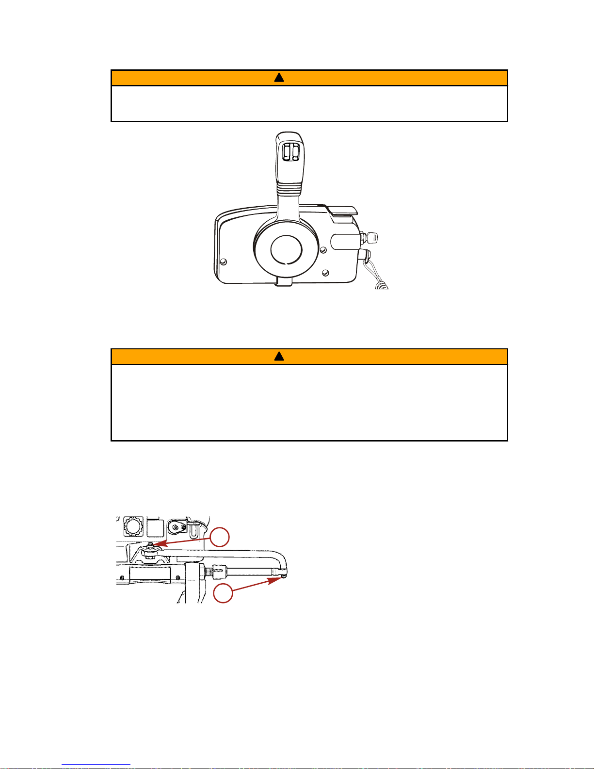
The steering link rod that connects the steering cable to the engine must be
fastened utilizing self‑locking nuts. These self‑locking nuts must never be
replaced with common nuts (nonlocking) as they will work loose and vibrate off,
freeing the link rod to disengage.
a - Self‑locking nuts
a
a
28984
GENERAL INFORMATION
eng 3
Page 14
Lanyard Stop Switch
The purpose of a lanyard stop switch is to turn off the engine when the operator
moves far enough away from the operator's position (as in accidental ejection
from the operator's position) to activate the switch. Tiller handle outboards and
some remote control units are equipped with a lanyard stop switch. A lanyard
stop switch can be installed as an accessory ‑ generally on the dashboard or
side adjacent to the operator's position.
A decal near the lanyard stop switch is a visual reminder for the operator to
attach the lanyard to their personal flotation device (PFD) or wrist.
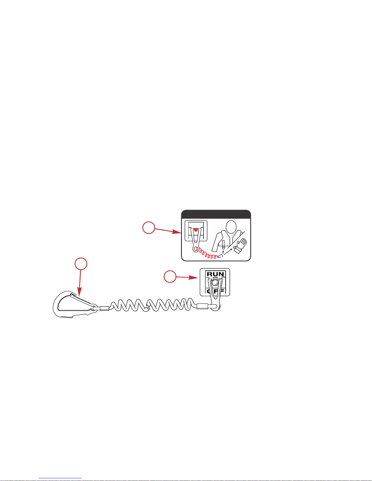
The lanyard cord is usually 122–152 cm (4–5 feet) in length when stretched out,
with an element on one end made to be inserted into the switch and a clip on
the other end for attaching to the operator's PFD or wrist. The lanyard is coiled
to make its at‑rest condition as short as possible to minimize the likelihood of
lanyard entanglement with nearby objects. Its stretched‑out length is made to
minimize the likelihood of accidental activation should the operator choose to
move around in an area close to the normal operator's position. If it is desired
to have a shorter lanyard, wrap the lanyard around the operator's wrist or leg,
or tie a knot in the lanyard.
a - Lanyard cord clip
b - Lanyard decal
c - Lanyard stop switch
Read the following Safety Information before proceeding.
c
a
b
53910
OFF
RUN
ATTACH LANYARD
GENERAL INFORMATION
4 eng
Page 15
Important Safety Information: The purpose of a lanyard stop switch is to stop
the engine when the operator moves far enough away from the operator's
position to activate the switch. This would occur if the operator accidentally falls
overboard or moves within the boat a sufficient distance from the operator's
position. Falling overboard and accidental ejections are more likely to occur in
certain types of boats such as low sided inflatables, bass boats, high
performance boats, and light, sensitive handling fishing boats operated by a
hand tiller. Falling overboard and accidental ejections are also likely to occur as
a result of poor operating practices such as sitting on the back of the seat or
gunwale at planing speeds, standing at planing speeds, sitting on elevated
fishing boat decks, operating at planing speeds in shallow or obstacle infested
waters, releasing your grip on a steering wheel or tiller handle that is pulling in
one direction, drinking alcohol or consuming drugs, or daring high speed boat
maneuvers.
While activation of the lanyard stop switch will stop the engine immediately, a
boat will continue to coast for some distance depending upon the velocity and
degree of any turn at shut down. However, the boat will not complete a full
circle. While the boat is coasting, it can cause injury to anyone in the boat's
path as seriously as the boat would when under power.
We strongly recommend that other occupants be instructed on proper starting
and operating procedures should they be required to operate the engine in an
emergency (if the operator is accidentally ejected).
!
WARNING
If the operator falls out of the boat, stop the engine immediately to reduce the
possibility of serious injury or death from being struck by the boat. Always
properly connect the operator to the stop switch using a lanyard.
!
WARNING
Avoid serious injury or death from deceleration forces resulting from
accidental or unintended stop switch activation. The boat operator should
never leave the operator's station without first disconnecting the stop switch
lanyard from the operator.
Accidental or unintended activation of the switch during normal operation is
also a possibility. This could cause any, or all, of the following potentially
hazardous situations:
• Occupants could be thrown forward due to unexpected loss of forward
motion ‑ a particular concern for passengers in the front of the boat who
could be ejected over the bow and possibly struck by the gearcase or
propeller.
• Loss of power and directional control in heavy seas, strong current, or
high winds.
• Loss of control when docking.
GENERAL INFORMATION
eng 5
Page 16
KEEP THE LANYARD STOP SWITCH AND LANYARD CORD IN GOOD
OPERATING CONDITION
Before each use, check to ensure the lanyard stop switch works properly. Start
the engine and stop it by pulling the lanyard cord. If the engine does not stop,
have the switch repaired before operating the boat.
Before each use, visually inspect the lanyard cord to ensure it is in good
working condition and that there are no breaks, cuts, or wear to the cord.
Check that the clips on the ends of the cord are in good condition. Replace any
damaged or worn lanyard cords.
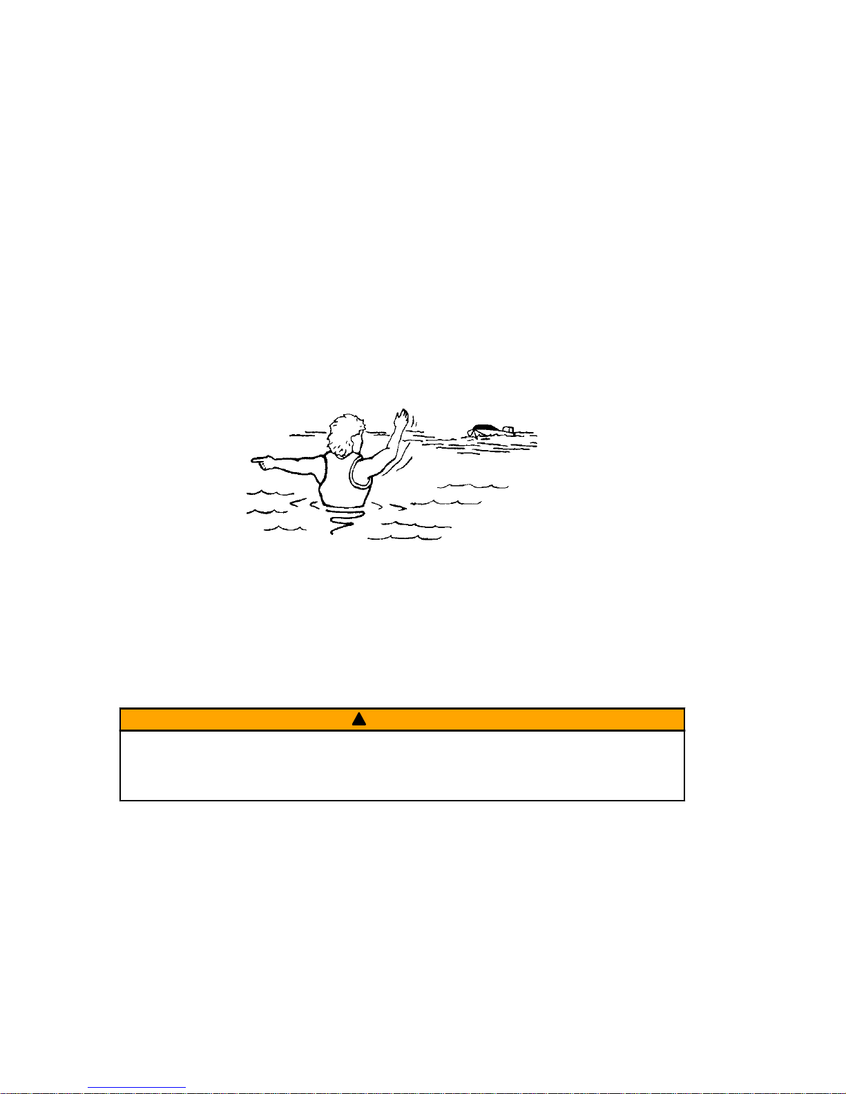
Protecting People in the Water
WHILE YOU ARE CRUISING
It is very difficult for a person standing or floating in the water to take quick
action to avoid a boat heading in his/her direction, even at slow speed.
21604
Always slow down and exercise extreme caution any time you are boating in an
area where there might be people in the water.
Whenever a boat is moving (coasting) and the outboard gear shift is in neutral
position, there is sufficient force by the water on the propeller to cause the
propeller to rotate. This neutral propeller rotation can cause serious injury.
WHILE THE BOAT IS STATIONARY
!
WARNING
A spinning propeller, a moving boat, or any solid device attached to the boat
can cause serious injury or death to swimmers. Stop the engine immediately
whenever anyone in the water is near your boat.
Shift the outboard into neutral and shut off the engine before allowing people to
swim or be in the water near your boat.
GENERAL INFORMATION
6 eng
Page 17

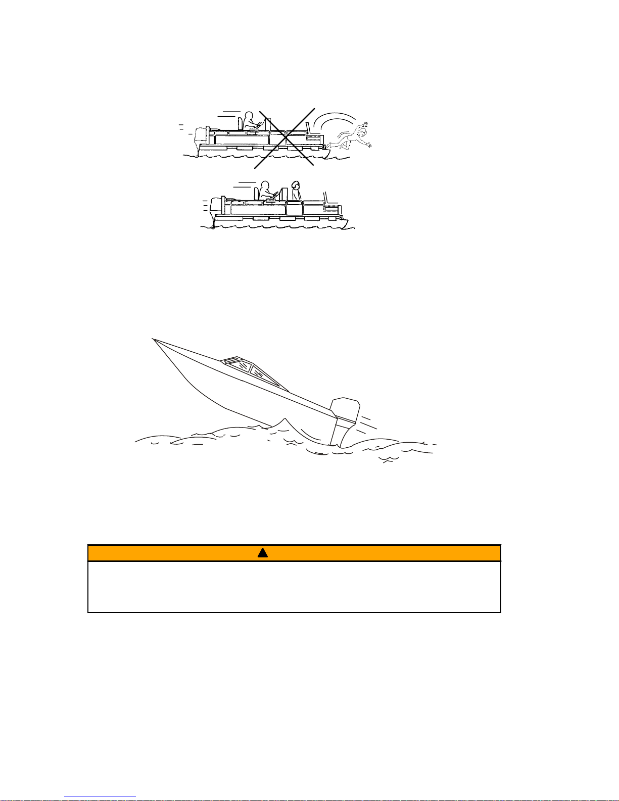
Passenger Safety Message ‑ Pontoon Boats and Deck Boats
Whenever the boat is in motion, observe the location of all passengers. Do not
allow any passengers to stand or use seats other than those designated for
traveling faster than idle speed. A sudden reduction in boat speed, such as
plunging into a large wave or wake, a sudden throttle reduction, or a sharp
change of boat direction, could throw them over the front of the boat. Falling
over the front of the boat between the two pontoons will position them to be run
over by the outboard.
BOATS HAVING AN OPEN FRONT DECK
No one should ever be on the deck in front of the fence while the boat is in
motion. Keep all passengers behind the front fence or enclosure.
Persons on the front deck could easily be thrown overboard or persons
dangling their feet over the front edge could get their legs caught by a wave
and pulled into the water.
26782
!
WARNING
Sitting or standing in an area of the boat not designed for passengers at
speeds above idle can cause serious injury or death. Stay back from the front
end of deck boats or raised platforms and remain seated while the boat is in
motion.
BOATS WITH FRONT MOUNTED, RAISED PEDESTAL FISHING SEATS
Elevated fishing seats are not intended for use when the boat is traveling faster
than idle or trolling speed. Sit only in seats designated for traveling at faster
speeds.
GENERAL INFORMATION
eng 7
Page 18
Any unexpected, sudden reduction in boat speed could result in the elevated
passenger falling over the front of the boat.
26783
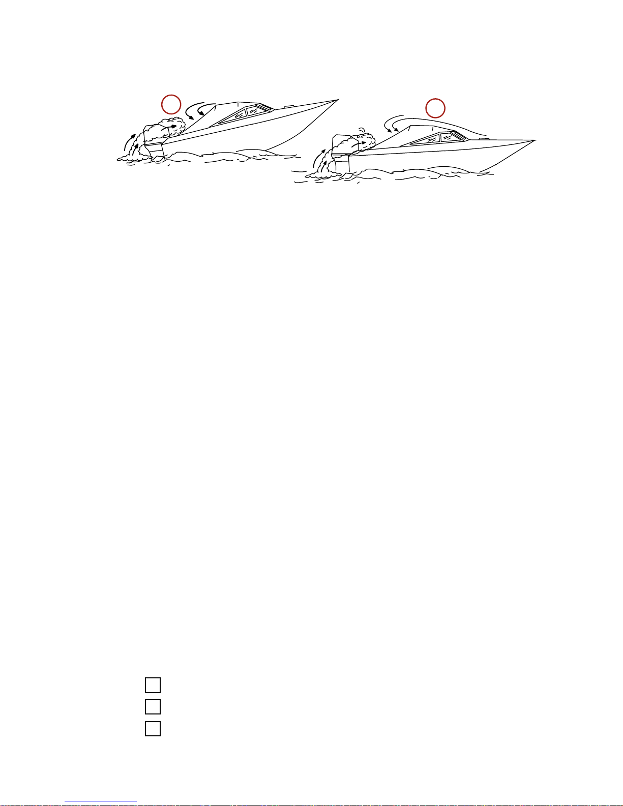
Wave and Wake Jumping
Operating recreational boats over waves and wake is a natural part of boating.
However, when this activity is done with sufficient speed to force the boat hull
partially or completely out of the water, certain hazards arise, particularly when
the boat enters the water.
26784
The primary concern is the boat changing direction while in the midst of the
jump. In such case, the landing may cause the boat to veer violently in a new
direction. Such a sharp change in direction can cause occupants to be thrown
out of their seats, or out of the boat.
!
WARNING
Wave or wake jumping can cause serious injury or death from occupants
being thrown within or out of the boat. Avoid wave or wake jumping whenever
possible.
There is another less common hazardous result from allowing your boat to
launch off a wave or wake. If the bow of your boat pitches down far enough
while airborne, upon water contact it may penetrate under the water surface
and submarine for an instant. This will bring the boat to a nearly instantaneous
stop and can send the occupants flying forward. The boat may also steer
sharply to one side.
GENERAL INFORMATION
8 eng
Page 19

Impact with Underwater Hazards
Your outboard may be equipped with a hydraulic trim and tilt system that also
contains a shock absorbing feature. This feature helps the outboard withstand
damage in the case of impact with an underwater object at low to moderate
speeds. At higher speeds, the force of the impact may exceed the system’s
ability to absorb the energy of the impact and cause serious product damage.
No impact protection exists while in reverse. Use extreme caution when
operating in reverse to avoid striking underwater objects.
Reduce speed and proceed with caution whenever you drive a boat in shallow
water areas or in areas where you suspect underwater obstacles may exist that
could be struck by the outboard or the boat bottom. The most significant
action you can take to help reduce injury or impact damage from striking
a floating or underwater object is to control the boat speed. Under these
conditions, boat speed should be kept to the minimum planing speed,
typically 24 to 40 km/h (15 to 25 mph).
26785
!
WARNING
Avoid serious injury or death from all or part of an outboard or drive unit
coming into the boat after striking a floating or underwater object. When
operating in waters where objects may be at the surface or just under the
surface of the water, reduce your speed and keep a vigilant lookout.
Examples of objects that can cause engine damage are dredging pipes,
bridge supports, wing dams, trees, stumps, and rocks.
Striking a floating or underwater object could result in any of an infinite number
of situations. Some of these situations could yield the following:
• Part of the outboard or the entire outboard could break loose and fly into
the boat.
• The boat could move suddenly in a new direction. A sharp change in
direction can cause occupants to be thrown out of their seats or out of the
boat.
• The boat's speed could rapidly reduce. This will cause occupants to be
thrown forward or even out of the boat.
GENERAL INFORMATION
eng 9
Page 20

• The outboard or boat could sustain impact damage.
After striking a submerged object, stop the engine as soon as possible and
inspect it for any broken or loose parts. If damage is present or suspected, the
outboard should be taken to an authorized dealer for a thorough inspection and
necessary repair.
The boat should also be checked for any hull fractures, transom fractures, or
water leaks. If water leaks are discovered after an impact, immediately activate
the bilge pump.
Operating a damaged outboard could cause additional damage to other parts
of the outboard or could affect control of the boat. If continued running is
necessary, do so at greatly reduced speeds.
!
WARNING
Operating a boat or engine with impact damage can result in product
damage, serious injury, or death. If the vessel experiences any form of
impact, have an authorized Mercury Marine dealer inspect and repair the
vessel or power package.
SAFETY INSTRUCTIONS FOR HAND-TILLED OUTBOARDS
No person or cargo should occupy the area directly in front of the outboard
while the boat is in motion. If an underwater obstacle is struck, the outboard will
tilt up and could seriously injure anyone occupying this area.
Models with Clamp Screws:
Some outboards come with transom bracket clamp screws. The use of clamp
bracket screws alone is insufficient to properly and safely secure the outboard
to the transom. Proper installation of the outboard includes bolting the engine to
the boat through the transom. Refer to Engine Installation ‑ Installing
Outboard for more complete installation information.
!
WARNING
Failure to correctly fasten the outboard could result in the outboard propelling
off the boat transom resulting in property damage, serious injury, or death.
Before operation, the outboard must be correctly installed with the required
mounting hardware.
GENERAL INFORMATION
10 eng
Page 21
This product must be secured to the transom with the required mounting
hardware. If the outboard strikes an underwater object, the required mounting
hardware prevents the outboard from propelling off the transom. A decal on the
swivel bracket reminds the installer of the potential hazard.
Avoid serious injury
or death. Secure
engine to transom
with bolts.
WARNING
37-896853-007
52375
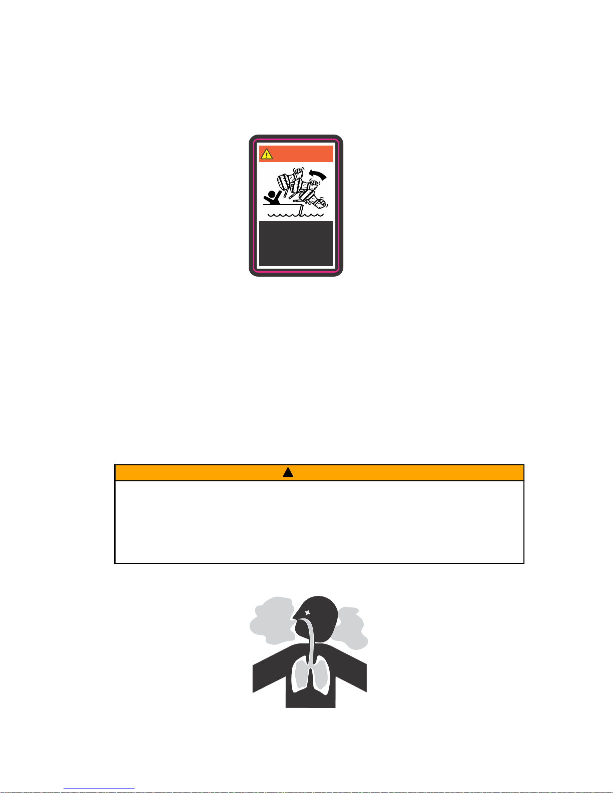
Exhaust Emissions
BE ALERT TO CARBON MONOXIDE POISONING
Carbon monoxide (CO) is a deadly gas that is present in the exhaust fumes of
all internal combustion engines, including the engines that propel boats, and
the generators that power boat accessories. By itself, CO is odorless, colorless,
and tasteless, but if you can smell or taste engine exhaust, you are inhaling
CO.
Early symptoms of carbon monoxide poisoning, which are similar to the
symptoms of seasickness and intoxication, include headache, dizziness,
drowsiness, and nausea.
!
WARNING
Inhaling engine exhaust gases can result in carbon monoxide poisoning,
which can lead to unconsciousness, brain damage, or death. Avoid exposure
to carbon monoxide.
Stay clear from exhaust areas when engine is running. Keep the boat
well‑ventilated while at rest or underway.
STAY CLEAR OF EXHAUST AREAS
41127
co
co
co
co
co
co
co
co
co
co
co
co
co
co
co
co
co
co
co
co
GENERAL INFORMATION
eng 11
Page 22
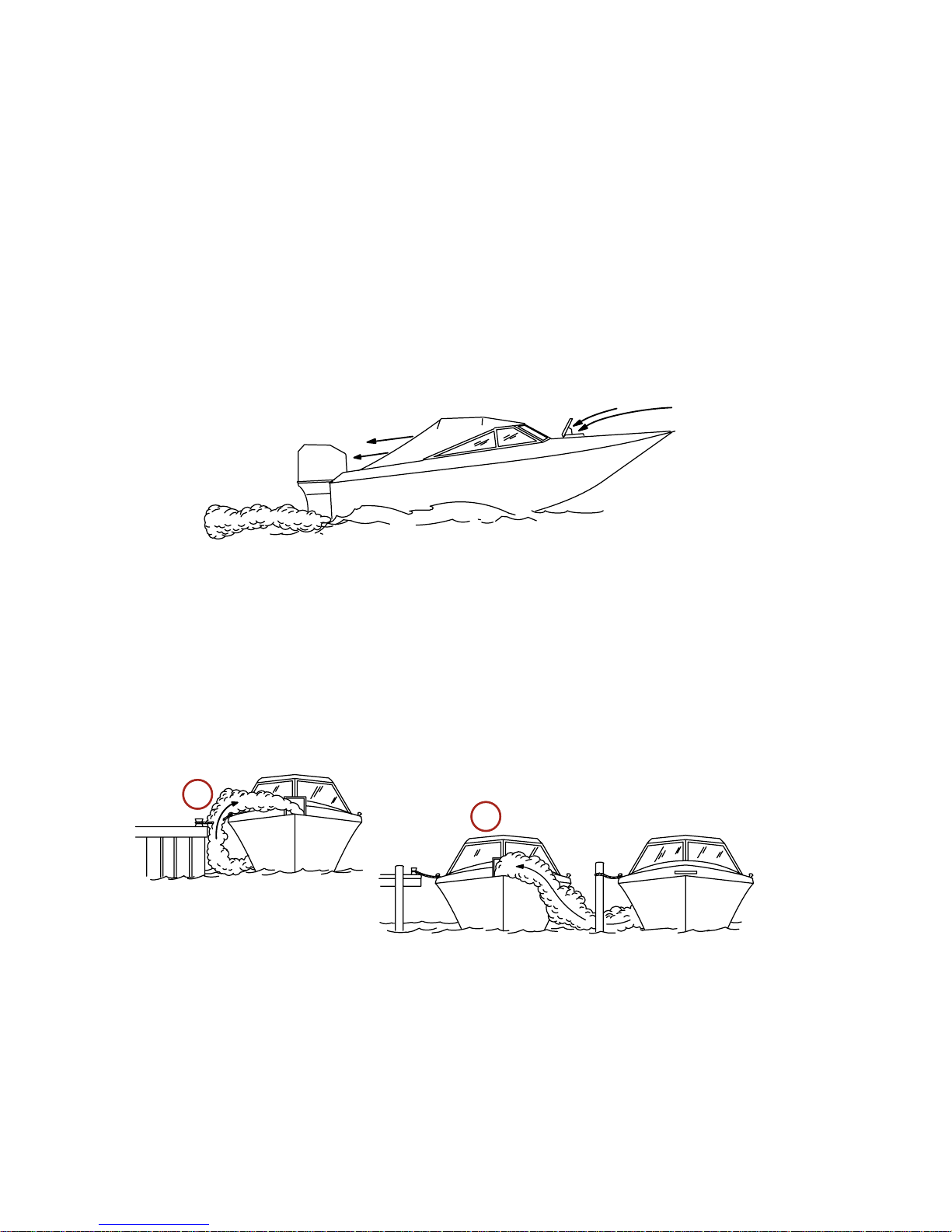
Engine exhaust gases contain harmful carbon monoxide. Avoid areas of
concentrated engine exhaust gases. When engines are running, keep
swimmers away from the boat, and do not sit, lie, or stand on swim platforms or
boarding ladders. While underway, do not allow passengers to be positioned
immediately behind the boat (platform dragging, teak/body surfing). This
dangerous practice not only places a person in an area of high engine exhaust
concentration, but also subjects them to the possibility of injury from the boat
propeller.
GOOD VENTILATION
Ventilate the passenger area, open side curtains or forward hatches to remove
fumes.
Example of desired air flow through the boat:
21622
POOR VENTILATION
Under certain running and/or wind conditions, permanently enclosed or canvas
enclosed cabins or cockpits with insufficient ventilation may draw in carbon
monoxide. Install one or more carbon monoxide detectors in your boat.
Although the occurrence is rare, on a very calm day, swimmers and
passengers in an open area of a stationary boat that contains, or is near, a
running engine may be exposed to a hazardous level of carbon monoxide.
1. Examples of poor ventilation while the boat is stationary:
a - Operating the engine when the boat is moored in a confined space
b - Mooring close to another boat that has its engine operating
21626
a
b
GENERAL INFORMATION
12 eng
Page 23
2. Examples of poor ventilation while the boat is moving:
a - Operating the boat with the trim angle of the bow too high
b - Operating the boat with no forward hatches open (station wagon effect)
Selecting Accessories for Your Outboard
Genuine Mercury Precision or Quicksilver Accessories have been specifically
designed and tested for your outboard. These accessories are available from
Mercury Marine dealers.
IMPORTANT: Check with your dealer before installing accessories. The misuse
of approved accessories or the use of nonapproved accessories can damage
the product.
Some accessories not manufactured or sold by Mercury Marine are not
designed to be safely used with your outboard or outboard operating system.
Acquire and read the installation, operation and maintenance manuals for all
your selected accessories.
Safe Boating Recommendations
To safely enjoy the waterways, familiarize yourself with local and all other
governmental boating regulations and restrictions and consider the following
suggestions.
Know and obey all nautical rules and laws of the waterways.
• We recommend that all powerboat operators complete a boating safety
course. In the U.S., the U.S. Coast Guard Auxiliary, the Power Squadron,
the Red Cross, and your state or provincial boating law enforcement
agency provide courses. For more information in the U.S., call the Boat
U.S. Foundation at 1‑800‑336‑BOAT (2628).
Perform safety checks and required maintenance.
• Follow a regular schedule and ensure that all repairs are properly made.
Check safety equipment onboard.
• Here are some suggestions of the types of safety equipment to carry
when boating:
Approved fire extinguishers
Signal devices: flashlight, rockets or flares, flag, and whistle or horn
Tools necessary for minor repairs
a
b
21628
GENERAL INFORMATION
eng 13
Page 24

Anchor and extra anchor line
Manual bilge pump and extra drain plugs
Drinking water
Radio
Paddle or oar
Spare propeller, thrust hubs, and an appropriate wrench
First aid kit and instructions
Waterproof storage containers
Spare operating equipment, batteries, bulbs, and fuses
Compass and map or chart of the area
Personal flotation device (one per person onboard)
Watch for signs of weather change and avoid foul weather and rough‑sea
boating.
Tell someone where you are going and when you expect to return.
Passenger boarding.
• Stop the engine whenever passengers are boarding, unloading, or are
near the back (stern) of the boat. Shifting the drive unit into neutral is not
sufficient.
Use personal flotation devices.
• Federal law requires that there be a U.S. Coast Guard‑approved life
jacket (personal flotation device), correctly sized and readily accessible
for every person onboard, plus a throwable cushion or ring. We strongly
advise that everyone wear a life jacket at all times while in the boat.
Prepare other boat operators.
• Instruct at least one person onboard in the basics of starting and
operating the engine and boat handling in case the driver becomes
disabled or falls overboard.
Do not overload your boat.
• Most boats are rated and certified for maximum load (weight) capacities
(refer to your boat's capacity plate). Know your boat's operating and
loading limitations. Know if your boat will float if it is full of water. When in
doubt, contact your authorized Mercury Marine dealer or the boat
manufacturer.
Ensure that everyone in the boat is properly seated.
GENERAL INFORMATION
14 eng
Page 25

• Do not allow anyone to sit or ride on any part of the boat that was not
intended for such use. This includes the backs of seats, gunwales,
transom, bow, decks, raised fishing seats, and any rotating fishing seat.
Passengers should not sit or ride anywhere that sudden unexpected
acceleration, sudden stopping, unexpected loss of boat control, or sudden
boat movement could cause a person to be thrown overboard or into the
boat. Ensure that all passengers have a proper seat and are in it before
any boat movement.
Never operate a boat while under the influence of alcohol or drugs. It is
the law.
• Alcohol or drugs can impair your judgment and greatly reduce your ability
to react quickly.
Know your boating area and avoid hazardous locations.
Be alert.
• The operator of the boat is responsible by law to maintain a proper
lookout by sight and hearing. The operator must have an unobstructed
view particularly to the front. No passengers, load, or fishing seats should
block the operator's view when the boat is above idle or planing transition
speed. Watch out for others, the water, and your wake.
Never drive your boat directly behind a water‑skier.
• Your boat traveling at 40 km/h (25 mph) will overtake a fallen skier who is
61 m (200 ft) in front of you in five seconds.
Watch fallen skiers.
• When using your boat for waterskiing or similar activities, always keep a
fallen or down skier on the operator's side of the boat while returning to
attend to the skier. The operator should always have the down skier in
sight and never back up to the skier or anyone in the water.
Report accidents.
• Boat operators are required by law to file a boating accident report with
their state boating law enforcement agency when their boat is involved in
certain boating accidents. A boating accident must be reported if 1) there
is loss of life or probable loss of life, 2) there is personal injury requiring
medical treatment beyond first aid, 3) there is damage to boats or other
property where the damage value exceeds $500.00, or 4) there is
complete loss of the boat. Seek further assistance from local law
enforcement.
Recording Serial Number
It is important to record the serial number and other important information for
future reference.
Please record the serial number of the engine as indicated (on the lower engine
cover and the cylinder block) in the space below. This number will come in
handy in the event of theft and it can help you to quickly identify the product
type.
GENERAL INFORMATION
eng 15
Page 26
Serial number:
Model year:
Model designation:
Year manufactured:
Certified Europe Insignia (as applicable):
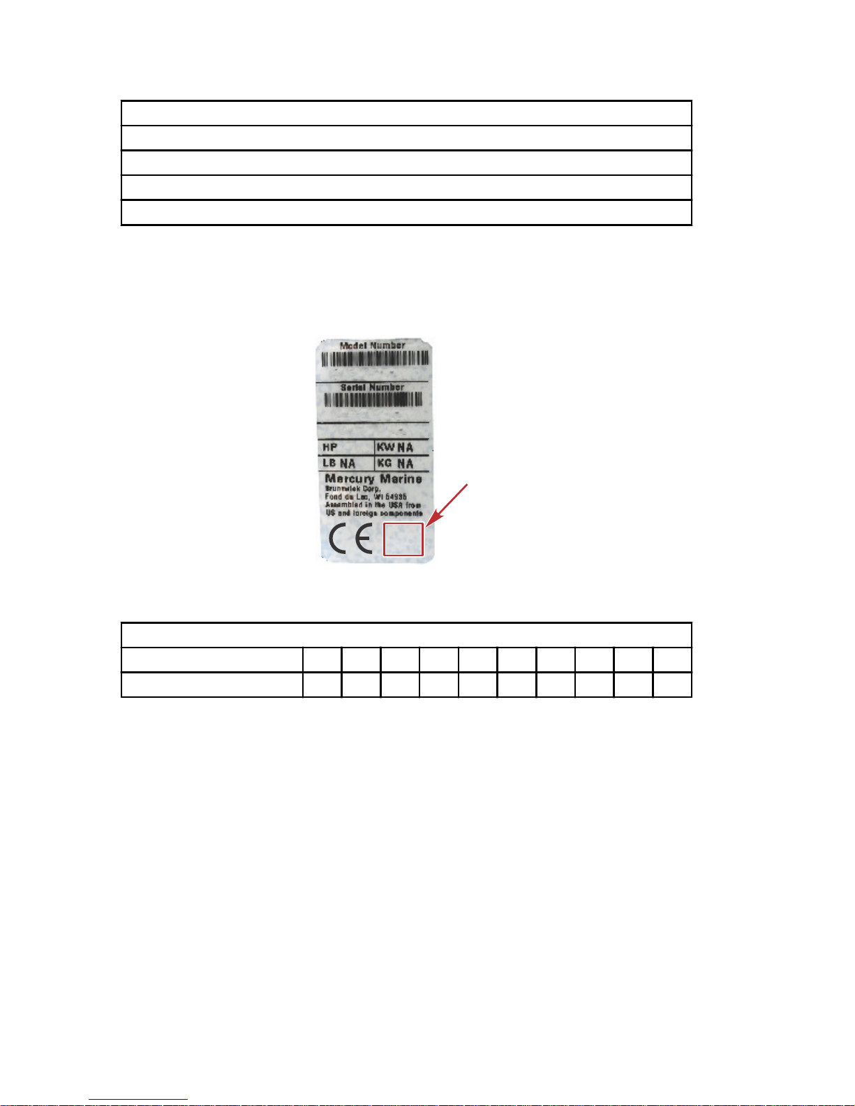
Model Year Production Code
The serial number decal lists the year of manufacture as an alpha code. This
code can be deciphered into a corresponding number utilizing the following
table.
XXXXXXXXX
XXXXXXXX
XXXX
AG
62972
Serial number decal alpha code
Model Year Manufactured Code
Alpha Production Code A B C D E F G H K X
Corresponding Number 1 2 3 4 5 6 7 8 9 0
Examples:
• XX = 2000
• HK = 2089
• AG = 2017
GENERAL INFORMATION
16 eng
Page 27

40/50 Specifications (Include English Units)
Model 40/50MH 40/50EH 40/50EHO
Overall length 1,143 mm
Overall width 384 mm
Overall height S = 1,225 mm, L = 1,352 mm, UL = 1,479 mm
Transom height S = 403 mm, L = 530 mm, UL = 657 mm
Weight
S = 72.0, L = 73.5,
UL = 75.0 kg
L = 78.5 kg
L = 80.0, UL = 81.5
kg
Maximum output 40 = 29.4 kW, 50 = 37.0 kW
Full throttle RPM 40 = 5000–5700, 50 = 5150–5850
Number of
cylinders
3
Displacement 697 mL
Bore and stroke 68 x 64 mm
Exhaust system Through hub exhaust
Lubrication Premixed fuel Oil injection
Fuel mixing ratio 50:1 120:1–50:1
Cooling system Thermostat controlled
Starting system Manual Electric (with manual backup)
Ignition CDI
Spark plugs
40: NGK B7HS‑10/BR7HS‑10 or Champion L‑82C/
RL‑82C (1.0 mm gap), 50: NGK B8HS‑10/BR8HS‑10 or
Champion L‑78C/RL‑78C (1.0 mm gap)
Alternator 12 V,130 W (12 V, 11 A)
Trim system Manual, 6 position
Engine oil Mercury or Quicksilver oil or recommended oil (TC‑W3)
Gear oil
Mercury or Quicksilver gear oil or API GL5, SAE #80 to
#90, approximately 500 mL
Fuel tank capacity 25 L (6.6 US gal)
Engine oil capacity –
Approximately 2.0 L
(0.53 US gal)
Gear reduction ratio 13:24
Fuel
Unleaded regular gasoline pump posted 87 octane
(research octane rating of 91)
GENERAL INFORMATION
eng 17
Page 28

Model 40/50EHPTO 40/50EO 40/50EPTO
Overall length 1,143 mm 630 mm
Overall width 384 mm 340 mm 355 mm
Overall height
S = 1,225,
L = 1,352,
UL = 1,479 mm
S = 1,212, L = 1,339, UL = 1,466
mm
Transom height S = 403, L = 530, UL = 657
Weight
S = 87.5, L =
89.0,
UL = 90.5 kg
S = 74.5,
L = 76.0 kg
S = 83.5, L =
85.0,
UL = 86.5 kg
Maximum output 40 = 29.4 kW, 50 = 37.0 kW
Full throttle RPM 40 = 5000–5700, 50 = 5150–5850
Number of cylinders 3
Displacement 697 mL
Bore and stroke 68 x 64 mm
Exhaust system Through hub exhaust
Lubrication Oil injection
Fuel mixing ratio 120:1–50:1
Cooling system Thermostat controlled
Starting system
Electric (manual
backup)
Electric
Ignition CDI
Spark plugs
40: NGK B7HS‑10/BR7HS‑10 or Champion L‑82C/
RL‑82C (1.0 mm gap), 50: NGK B8HS‑10/BR8HS‑10
or Champion L‑78C/RL‑78C (1.0 mm gap)
Alternator 12 V,130 W (12 V, 11 A)
Trim system Power trim
Manual, 6
position
Power trim
Engine oil
Mercury or Quicksilver motor oil or recommended oil
(TC‑W3)
Gear oil
Mercury or Quicksilver gear oil or API GL5, SAE #80 to
#90, approximately 500 mL
Fuel tank capacity 25 L (6.6 US gal)
Engine oil capacity Approximately 2.0 L (0.53 US gal)
Gear reduction ratio 13:24
Fuel
Unleaded regular gasoline pump posted 87 octane
(research octane rating of 91)
GENERAL INFORMATION
18 eng
Page 29

Model W50MH W50EHPT W50EO
Overall length 1,145 mm 630 mm
Overall width 384 mm 355 mm 340 mm
Overall height L = 1,413 mm L = 1,410 mm
Transom height 550 mm
Weight L = 79.0 kg L = 84.0 kg L = 81.5 kg
Maximum output 37.0 kW
Full throttle RPM 5150–5850
Number of
cylinders
3
Displacement 697 mL
Bore and stroke 68 x 64 mm
Exhaust system Through hub exhaust
Lubrication Premixed fuel Oil injection
Fuel mixing ratio 50:1 120:1 ‑ 50:1
Cooling system Thermostat controlled
Starting system Manual
Electric (w/
manual backup)
Electric
Ignition CDI
Spark plugs
NGK B8HS‑10/BR8HS‑10 or Champion L‑78C/RL‑78C
(1.0 mm gap)
Alternator 12 V,130 W (12 V, 11 A)
Trim system
Manual, 6
position
Power trim Manual, 6 position
Engine oil
Mercury or Quicksilver motor oil or recommended oil
(TC‑W3)
Gear oil
Mercury or Quicksilver gear oil or API GL5, SAE #80 to
#90, approximately 700 mL
Fuel tank capacity 25 L (6.6 US gal)
Engine oil
capacity
–
Approximately 2.0 L
(0.53 US gal)
Gear reduction
ratio
12:23
Fuel
Unleaded regular gasoline pump posted 87 octane
(research octane rating of 91)
GENERAL INFORMATION
eng 19
Page 30
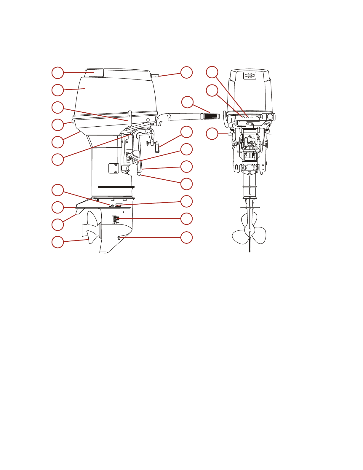
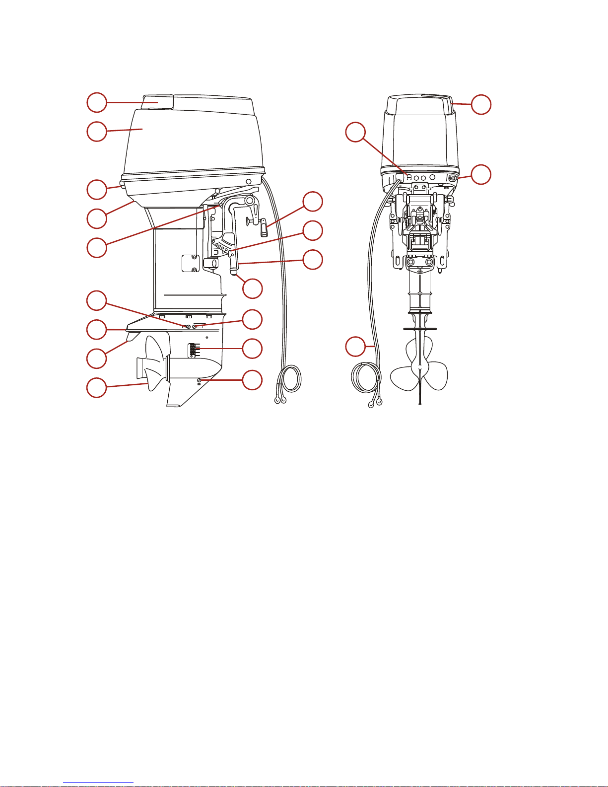
COMPONENT IDENTIFICATION
40MH/W50MH
a - Tilt handle
b - Top cowl
c - Shift lever
d - Cowl latch
e - Water pump indicator hole
f - Reverse lock lever
g - Water plug
h - Anti‑ventilation plate
i - Trim tab
j - Propeller
k - Manual start handle
l - Throttle grip
m - Clamp screw
n - Trim position pin
o - Transom bracket
p - Anode
q - Oil drain plug (upper)
r - Water intake
38270
a
b
c
d
e
f
g
h
i
j
k
l
m
n
o
p
q
r
s
t
u
f
GENERAL INFORMATION
20 eng
Page 31

s - Oil drain plug (lower)
t - Stop switch
u - Choke knob
GENERAL INFORMATION
eng 21
Page 32

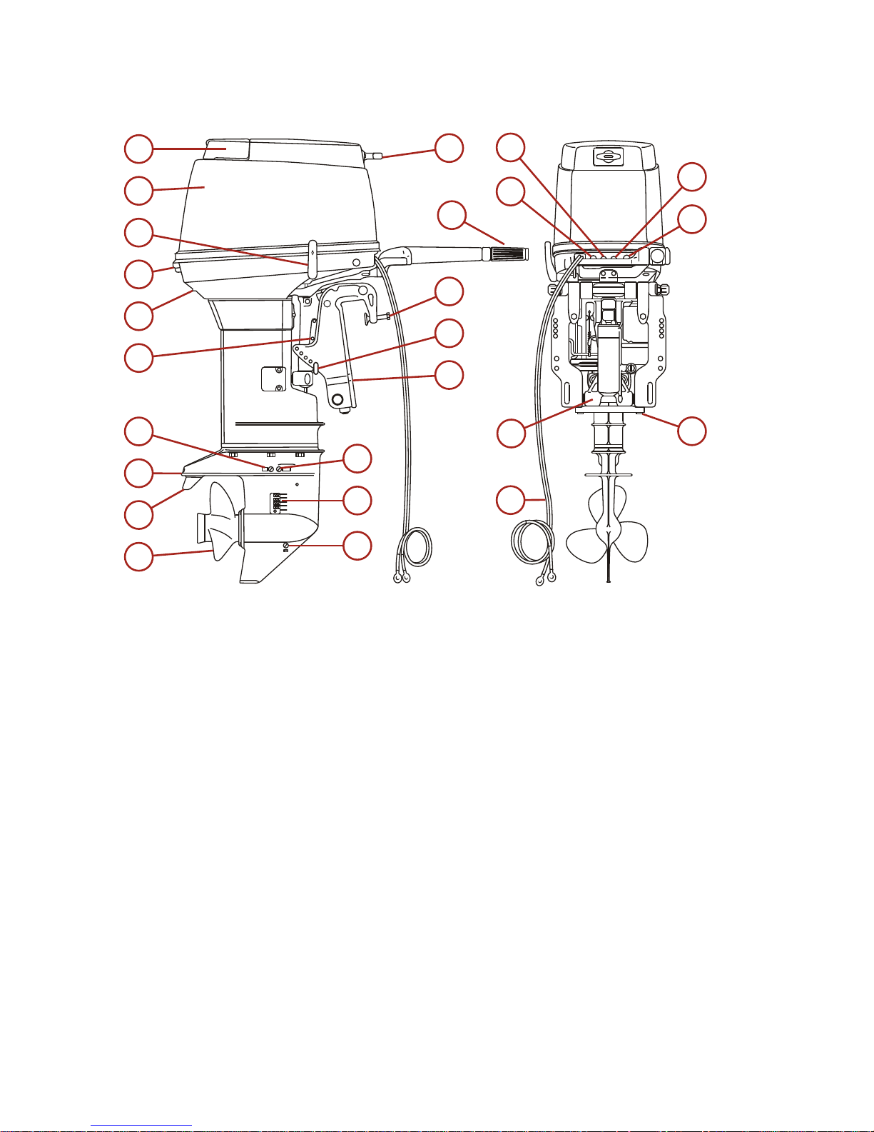
40EH/50EH
a - Tilt handle
b - Top cowl
c - Shift lever
d - Cowl latch
e - Water pump indicator hole
f - Reverse lock lever
g - Water plug
h - Anti‑ventilation plate
i - Trim tab
j - Propeller
k - Manual start handle
l - Throttle grip
m - Clamp screw
n - Trim position pin
o - Transom bracket
p - Anode
q - Oil drain plug (upper)
r - Water intake
s - Oil drain plug (lower)
38271
a
b
c
d
e
f
g
h
i
j
k
l
m
n
o
p
q
r
s
t
u
f
w
v
GENERAL INFORMATION
22 eng
Page 33

t - Stop switch
u - Choke knob
v - Battery cables
w - Start button
GENERAL INFORMATION
eng 23
Page 34

40EHO/50EHO
a - Tilt handle
b - Top cowl
c - Shift lever
d - Cowl latch
e - Water pump indicator hole
f - Reverse lock lever
g - Water plug
h - Anti‑ventilation plate
i - Trim tab
j - Propeller
k - Manual start handle
l - Throttle grip
m - Clamp screw
n - Trim position pin
o - Transom bracket
p - Anode
q - Oil drain plug (upper)
r - Water intake
s - Oil drain plug (lower)
38272
a
b
c
d
e
f
g
h
i
j
k
l
m
n
o
p
q
r
s
t
u
f
x
v
w
GENERAL INFORMATION
24 eng
Page 35

t - Stop switch
u - Choke knob
v - Battery cables
w - Low oil light
x - Start button
GENERAL INFORMATION
eng 25
Page 36
40EHPTO/50EHPTO
a - Tilt handle
b - Top cowl
c - Shift lever
d - Cowl latch
e - Water pump indicator hole
f - Tilt stopper
g - Water plug
h - Anti‑ventilation plate
i - Trim tab
j - Propeller
k - Manual start handle
l - Throttle grip
m - Clamp screw
n - Trim position pin
o - Transom bracket
p - Oil drain plug (upper)
q - Water intake
r - Oil drain plug (lower)
s - Stop switch
38273
a
b
c
d
e
f
g
h
i
j
k
l
m
n
o
p
q
r
s
t
u
y
v
w
x
GENERAL INFORMATION
26 eng
Page 37

t - Choke knob
u - Power trim and tilt
v - Battery cables
w - Low oil light
x - Start button
y - Anode
GENERAL INFORMATION
eng 27
Page 38
40EO/50EO
a - Tilt handle
b - Top cowl
c - Cowl latch
d - Water pump indicator hole
e - Reverse lock lever
f - Water plug
g - Anti‑ventilation plate
h - Trim tab
i - Propeller
j - Clamp screw
k - Trim position pin
l - Transom bracket
m - Anode
n - Oil drain plug (upper)
o - Water intake
p - Oil drain plug (lower)
q - Choke knob
r - Battery cables
s - Oil fill door
38274
a
b
c
d
e
f
g
h
i
j
k
l
m
n
o
p
s
q
r
t
GENERAL INFORMATION
28 eng
Page 39

t - Fuel connector
GENERAL INFORMATION
eng 29
Page 40

40EPTO/50EPTO
a - Tilt handle
b - Top cowl
c - Cowl latch
d - Water pump indicaor hole
e - Tilt stopper
f - Water plug
g - Anti‑ventilation plate
h - Trim tab
i - Propeller
j - Clamp screw
k - Trim position pin
l - Transom bracket
m - Oil drain plug (upper)
n - Water intake
o - Oil drain plug (lower)
p - Choke knob
q - Power trim and tilt
r - Battery cables
s - Oil fill door
38275
a
b
c
d
e
f
g
h
i
j
k
l
m
n
o
s
p
q
v
r
t
u
GENERAL INFORMATION
30 eng
Page 41

t - Power trim and tilt switch
u - Fuel connector
v - Anode
GENERAL INFORMATION
eng 31
Page 42

Removing the Motor
1. Verify the engine has cooling water supplied.
2. Disconnect the fuel connector and run the engine out of fuel. Pull the
choke out when the engine begins to stall. This will help evacuate the
remaining fuel out of the carburetors.
3. After the engine has stalled, the remote control cable, the battery cables,
and the bracket fixing bolts and nuts from the motor.
4. Remove the motor from the hull and completely drain the water from the
outboard. Be sure to keep the engine higher than the propeller whenever
you carry the motor.
Carrying the Motor
Be sure to keep the engine vertical whenever you carry the motor.
39893
When carrying or putting the engine up for storage, make sure the side with the
electric pump or the power trim and tilt is down, otherwise air will enter the
power trim and tilt pump system.
38384
TRANSPORTING
32 eng
Page 43

Trailering Boat/Outboard
The boat should be trailered with the outboard in the vertical (normal running),
fully down position.
NOTE: Trailering in the tilted position may cause damage to the motor, boat,
etc. If trailering with the engine fully down is not acceptable (the gearcase skeg
is too close to the road in a vertical position), fix the motor securely using a
device (like a transom saver bar) in the tilted position.
39895
Shift the outboard to the forward gear. This prevents the propeller from
spinning freely.
If additional ground clearance is required, the outboard should be tilted up
using an accessory outboard support device. Refer to your local dealer for
recommendations. Additional clearance may be required for railroad crossings,
driveways, and trailer bouncing.
IMPORTANT: The tilt lock and shallow water drive feature (tiller handle models)
on the outboard are not intended to support the outboard in the tilted position
when trailering.
Mooring with the Engine Tilted Up
When the engine has been stopped and it will not be used for a long time, or
when mooring in shallow water, tilt the engine up to prevent damage to the
propeller and gearcase.
MH, EH, EHO, EO
TRANSPORTING
eng 33
Page 44

1. Disconnect the fuel connector from the engine.
38345
2. Set the reverse lock lever on the starboard side to release by turning it
downward.
38366
IMPORTANT: When tilting up or down, be sure your finger, or hand, is not
placed in‑between the swivel bracket and transom bracket. Be sure to tilt down
the outboard slowly.
3. Tilt the engine up entirely. The outboard will lock in the raised position.
38367
TRANSPORTING
34 eng
Page 45

4. To tilt the outboard down. Turn the reverse lock lever upward (toward
release). Tilt the engine up slightly and then tilt the engine down. The
reverse lock will release automatically.
39890
EHPTO, EPTO
1. Disconnect the fuel connector from the engine.
38345
2. Operate the power trim and tilt switch on the remote control lever and tilt
the engine up.
a - UP
b - Down (DN)
c - Off
d - On
38378
b
a
c
d
TRANSPORTING
eng 35
Page 46

3. The engine can also be tilted up using the switch provided under the
bottom cowl.
a - Power trim and tilt switch
4. Lock the tilt with the tilt stopper after the engine has been tilted up.
a - Tilt stopper
38379
a
38381
a
TRANSPORTING
36 eng
Page 47
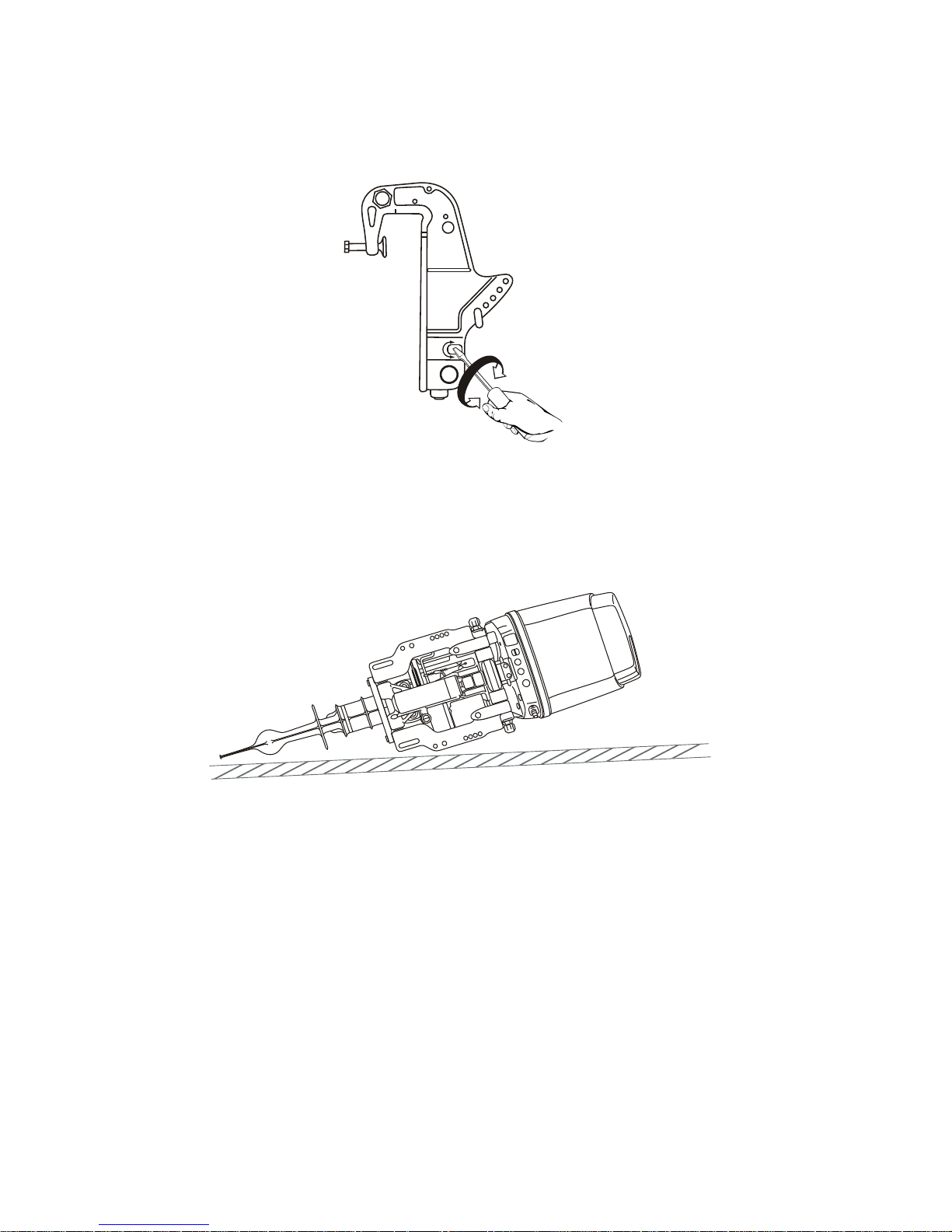
5. Manual tilting: If the engine cannot be trimmed up electrically, turn the
manual valve a few turns counterclockwise. This will allow manual tilting
of the engine.
38382
Storing the Motor
Keep the motor in a vertical position when you store it.
NOTE: If you store the motor in a horizontal position, lay the motor as shown in
the figure.
38384
EH, EHO, EO
IMPORTANT: When removing the motor from the package or removing the
motor from the boat, never release the reverse lock lever. If the reverse lock
lever is released, it will be very easy for the transom bracket to spring up to the
tilting direction because it is not secured.
1. Secure the transom bracket to the outboard with a rope.
TRANSPORTING
eng 37
Page 48

2. Pay attention to the tilting direction so as not to be injured by the transom
bracket.
a - Reverse lock lever
b - Lock
c - Transom bracket
d - Tilting direction
e - Rope
Transporting Portable Fuel Tanks
!
WARNING
Avoid serious injury or death from a gasoline fire or explosion. Follow the
transporting instructions supplied with the portable fuel tank. Transport the
fuel tank in a well ventilated area away from open flame or sparks.
MANUAL VENTING TYPE FUEL TANK
Close the fuel tank air vent when transporting tank. This will prevent escape of
fuel or vapors from tank.
26793
AUTO-VENTING TYPE FUEL TANK
1. Disconnect the remote fuel line from tank. This will close the air vent and
prevent escape of fuel or vapors from tank.
2. Install tether cap over the fuel line connector stem. This will protect the
connector stem from being accidentally pushed‑in, allowing fuel or vapor
to escape.
a - Connector stem
b - Tether cap
39894
a
b
c
d
e
F
a
b
26794
TRANSPORTING
38 eng
Page 49

Fuel Requirements
IMPORTANT: Use of improper gasoline can damage your engine. Engine
damage resulting from the use of improper gasoline is considered misuse
of the engine and will not be covered under the limited warranty.
FUEL RATINGS
Mercury outboard engines will operate satisfactorily with any major brand of
unleaded gasoline that meets the following specifications:
USA and Canada ‑ A posted pump octane rating of 87 (R+M)/2, minimum, for
most models. Premium gasoline 91 (R+M)/2 octane is also acceptable for most
models. Do not use leaded gasoline.
Outside USA and Canada ‑ A posted pump octane rating of 91 RON,
minimum, for most models. Premium gasoline (95 RON) is also acceptable for
all models. Do not use leaded gasoline.
USING REFORMULATED (OXYGENATED) GASOLINE (USA ONLY)
Reformulated gasoline is required in certain areas of the USA and is
acceptable for use in your Mercury Marine engine. The only oxygenate
currently in use in the USA is alcohol (ethanol, methanol, or butanol).
GASOLINE CONTAINING ALCOHOL
Bu16 Butanol Fuel Blends
Fuel blends of up to 16.1% butanol (Bu16) that meet the published Mercury
Marine fuel rating requirements are an acceptable substitute for unleaded
gasoline. Contact your boat manufacturer for specific recommendations on
your boat's fuel system components (fuel tanks, fuel lines, and fittings).
Methanol and Ethanol Fuel Blends
IMPORTANT: The fuel system components on your Mercury Marine engine will
withstand up to 10% alcohol (methanol or ethanol) content in the gasoline. Your
boat's fuel system may not be capable of withstanding the same percentage of
alcohol. Contact your boat manufacturer for specific recommendations on your
boat's fuel system components (fuel tanks, fuel lines, and fittings).
Be aware that gasoline containing methanol or ethanol may cause increased:
• Corrosion of metal parts
• Deterioration of rubber or plastic parts
• Fuel permeation through the rubber fuel lines
• Likelihood of phase separation (water and alcohol separating from the
gasoline in the fuel tank)
FUEL AND OIL
eng 39
Page 50

!
WARNING
Fuel leakage is a fire or explosion hazard, which can cause serious injury or
death. Periodically inspect all fuel system components for leaks, softening,
hardening, swelling, or corrosion, particularly after storage. Any sign of
leakage or deterioration requires replacement before further engine
operation.
IMPORTANT: If you use gasoline that contains or might contain methanol or
ethanol, you must increase the frequency of inspection for leaks and
abnormalities.
IMPORTANT: When operating a Mercury Marine engine on gasoline containing
methanol or ethanol, do not store the gasoline in the fuel tank for long periods.
Cars normally consume these blended fuels before they can absorb enough
moisture to cause trouble; boats often sit idle long enough for phase separation
to take place. Internal corrosion may occur during storage if alcohol has
washed protective oil films from internal components.
Oil Recommendation
Recommended Oil
Mercury or Quicksilver Premium 2‑Cycle TC‑W3
Outboard Oil
IMPORTANT: Oil must be NMMA certified TC‑W3 2‑Cycle oil.
Mercury or Quicksilver Premium TC‑W3 2‑Cycle oil is recommended for this
engine. For added protection and lubrication, Mercury or Quicksilver Premium
Plus TC‑W3 2‑Cycle oil is recommended. If Mercury or Quicksilver outboard oil
is not available, substitute another brand of 2‑cycle outboard oil that is NMMA
Certified TC‑W3. Severe engine damage may result from use of an inferior oil.
Non‑Oil Injected Models: MH, EH
Add engine oil into the fuel tank. The mixing ratio with gasoline is 50:1 (50 parts
gasoline and one part oil). Mix well by hand. The mixing ratio during break‑in
running is 25:1.
Mixing ratio
Gasoline
Engine Oil
During break‑in 25 1
After break‑in 50 1
Pour oil into the fuel tank.
Pour gasoline into the fuel tank.
ENGINE BREAK-IN
Engine Break‑in Fuel Mixture
Use a 25:1 gasoline/oil mixture in the first tank of fuel.
FUEL AND OIL
40 eng
Page 51
Engine Break‑in Procedure
Refer to Operation ‑ Engine Break‑In Procedure for correct break‑in
procedure.
Oil Injected Models: EHO, EHPTO, EO, EPTO
The required amount of engine oil is automatically supplied from the oil pump
according to the engine running conditions.
IMPORTANT: During engine break‑in, engine oil must be added to the gasoline
in addition to the oil, which is automatically supplied from the oil tank.
Mixing ratio (during break‑in on oil injected models)
Gasoline Engine Oil
During break‑in 50 1
After break‑in Automatic: Fill up engine oil tank regularly
Pour oil into the fuel tank.
Pour gasoline into the fuel tank. Shake well to mix oil and fuel.
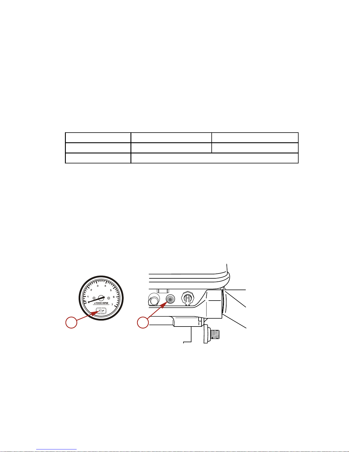
Alarm for low engine oil level
If the level in the oil tank falls below 0.4 L (0.105 US gal), the low engine oil
alarm will be triggered. The engine oil tank capacity is 2 L (0.53 US gal).
EO, EPTO: The low oil light in the tachometer lights and the buzzer in the
remote control box sounds if the engine oil level falls below 0.4 L
(0.105 US gal).
EHO, EHPTO: The low oil light is on the front portion of the bottom cowl. The
light will come on if the engine oil level falls below 0.4 L (0.105 US gal).
a - Low oil light in tachometer
b - Low oil light on lower engine cover
Resetting the low oil level alarm:
1. Reduce engine speed to trolling RPM and steer towards a safe area with
calm water. Set the remote control lever to Neutral (buzzer will stop).
38322
b
a
FUEL AND OIL
eng 41
Page 52

2. Turn off the ignition switch, and fill up the oil tank with recommended
engine oil.
3. Start the engine, and shift into gear carefully.
4. Confirm that the indicator lamp goes out and the buzzer does not sound.
Replenishing the oil in the engine oil tank:
1. Open the oil fill door on the top cowl.
2. Remove the oil tank cap.
3. Fill up the tank with genuine engine oil or recommended oil.
a - Recommended engine
oil
b - Oil fill door
c - Oil tank cap
IMPORTANT: Please follow the instructions below.
1. In the unlikely event that gasoline is filled into the oil tank by mistake,
drain the oil tank completely, and consult an authorized service shop for
advice.
2. Check the amount of oil in the oil tank visually before starting the engine.
Oil pump air vent
Visually check whether there is air in the oil through the oil line connecting the
oil tank with the oil pump. If present, purge the air as follows:
Loosen the air vent screw on the oil pump to purge the air, and tighten it when
all air, as seen through the oil line to the oil pump has been purged.
a - Air vent screw
b - To check valve
c - Oil line
d - Oil line
e - From oil filter
NOTE: Wipe off any spilled oil with a rag, and dispose of it.
38323
a
b
c
38335
a
b
c
d
e
FUEL AND OIL
42 eng
Page 53
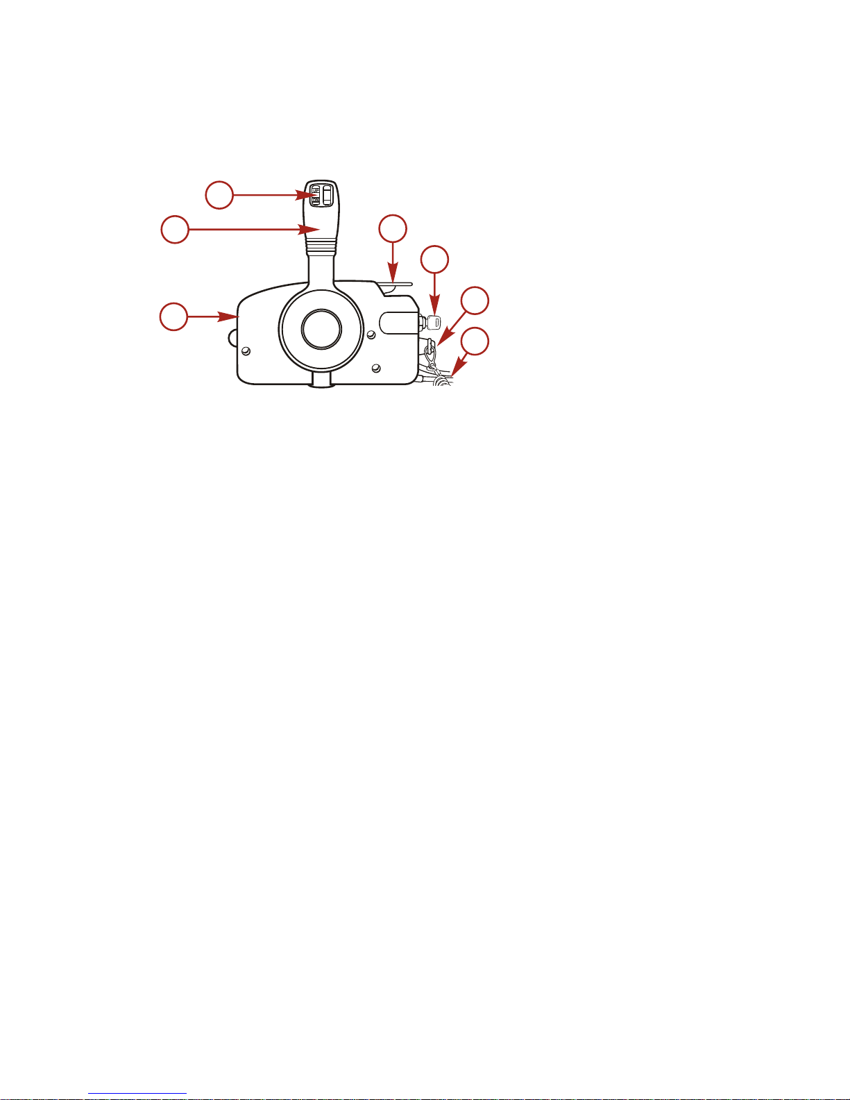
Remote Control Features
Your boat may be equipped with the remote control shown. If not, consult your
dealer for a description of the functions and operations of the remote control.
a - Remote control box
b - Remote control handle
c - Power trim and tilt switch
d - Neutral warm‑up lever
e - Ignition key switch
f - Lanyard stop switch
g - Lanyard cord
Tilting Outboard
BASIC TILTING OPERATION
The tilt feature allows the operator to tilt the outboard to a higher tilt angle for
operation in shallow water, or tilt the outboard to the full up position.
When running the outboard, keep the tilt lever in the release position. This
allows the outboard to return to the running position if the outboard should hit
an underwater obstacle and be lifted up.
Moving the tilt lever to the tilt position will allow the outboard to lock into the
shallow water drive position or the full up position.
Shallow Water Operation
The outboard is equipped with a shallow water tilt feature that allows you to tilt
the outboard to a higher tilt angle to prevent hitting bottom.
IMPORTANT: Before tilting the outboard into the shallow water drive position,
reduce engine speed to idle and shift engine into neutral gear.
39924
a
b
c
d
e
f
g
FEATURES AND CONTROLS
eng 43
Page 54

NOTE: Please follow the instructions below:
• When running in shallow water, take care the water in take is submerged
at all times and that water is continuously running out of the water pump
indicator hole.
• Be sure to run slowly when using the shallow water drive. Running at
higher speeds will result in lack of control and may cause damage to the
gearcase.
• Ensure that the motor does not strike the bottom, especially when running
in Reverse (R). If the motor strikes the bottom while in reverse the impact
is transmitted to the transom, risking damage to both the motor and the
boat.
SHALLOW WATER RUNNING POSITION
MH, EH, EHO, EO
1. Set the reverse lock lever provided on the starboard side to Release by
turning it downward.
38366
2. Tilt the engine up approximately 45° and lower it. The engine will now be
set to the shallow water setting.
38367
FEATURES AND CONTROLS
44 eng
Page 55

3. Releasing the shallow water setting:
a. Turn the reverse lock lever upward to set them in the lock position.
b. Tilt up the engine slightly and let it go down. The shallow water setting
is released.
c. The engine is released from shallow water setting, and locked at
normal running position.
EHPTO, EPTO
Tilt up the engine using the power trim and tilt system.
Trim Adjustment
Trim of the motor can be adjusted to suit the transom angle and loading
conditions of your boat. Be sure to maintain the anti‑ventilation plate parallel to
the water level during cruising.
The following instructions explain how to set the best angle of the boat. Proper
adjustment allows the boat to run stable, achieve optimum performance, and
minimize steering effort.
MH, EH, EHO, EO
The trim angle is adjusted by setting the trim position pin in the correct trim
position. Arrange passengers and load in the boat so the weight is distributed
evenly.
•
Correct trim: The trim angle is optimum when the boat is parallel to the
water surface while running.
39891
FEATURES AND CONTROLS
eng 45
Page 56

•
Trim down: If the trim angle is excessive, the bow will rise out of the
water and the speed will decrease.
a - Select a lower hole
•
Trim up: If the trim angle is low, the bow will dip into the water, the speed
will decrease, and water may enter the boat. In this case, the trim angle
should be increased by setting the trim position pin in a higher hole.
a - Select a higher hole
EHPTO, EPTO
The provided power trim and tilt can be adjusted to set the desired trim angle of
the engine in relation to the transom shape, planing speeds, and load. It is
imperative that the trim angle is adjusted correctly. Incorrect adjustment will
cause the boat to sway, deteriorate engine performance, and may cause
unsafe steering conditions.
IMPORTANT: The power trim and tilt can be set to trim angle, however, avoid
cruising with the engine tilted in the tilt range. Operating the boat in this
manner, the engine may suck air into the water cooling system resulting in
engine overheating.
38372
a
38374
a
FEATURES AND CONTROLS
46 eng
Page 57

How to use the trim gauge: When the trim angle is set as desired, take a
reading off the trim gauge, and record it for future reference.
a - Trim angle adjustable
range
b - 74°
c - 8°
d - 28°
•
Correct trim: The trim angle is optimum when the boat is parallel to the
water surface while running.
•
Trim down: If the trim angle is excessive, the bow will rise out of the
water and the speed will decrease. If this occurs, press the switch on the
remote control level to down (DN).
a - Remote control lever: Down (DN)
38375
a
b
d
c
38376
a
FEATURES AND CONTROLS
eng 47
Page 58

•
Trim up: If the trim angle is low, the bow will dip into the water and the
speed will decrease. Water may also enter the boat. In this case, the trim
angle should be increased by pressing the switch on the remote control
lever to UP.
a - Remote control lever: UP
Steering Friction Adjustment
Steering friction can be adjusted according to your preference with the steering
co‑pilot.
!
WARNING
Insufficient friction adjustment can cause serious injury or death due to loss
of boat control. When setting the friction adjustment, maintain sufficient
steering friction to prevent the outboard from steering into a full turn if the
tiller handle or steering wheel is released.
Adjust the steering co‑pilot to achieve desired steering friction.
• Turn clockwise for more friction.
• Turn counterclockwise for less friction.
MH, EH, EHO, EO
a - Tight
b - Loose
c - Copilot
37377
a
38386
c
a
b
FEATURES AND CONTROLS
48 eng
Page 59

EHPTO, EPTO
a - Tight
b - Loose
c - Copilot
Throttle Grip Turning Friction Adjustment
Turn the screw clockwise to tighten friction and turn the screw counterclockwise
to loosen friction.
a - Loosen friction
b - Tighten friction
Trim Tab Adjustment
Propeller steering torque will cause the boat to pull in one direction. This
steering torque is a normal result from the outboard not trimmed with the
propeller shaft parallel to the water surface. The trim tab can help compensate
for this steering torque in many cases and can be adjusted within limits to
reduce any unequal steering effort.
• Operate the boat at normal cruising speed with the outboard set at the
desired operating angle position. Turn the boat left and right and note the
direction the boat turns more easily.
• If an adjustment is necessary, loosen the trim tab bolt and make small
adjustments at a time.
• After the adjustment, securely tighten the trim tab bolt.
NOTE: Inspect the tightness of the bolt and the trim tab at regular intervals.
Due to corrosion, the trim tab will wear down over time.
38387
a
b
c
38388
a
b
FEATURES AND CONTROLS
eng 49
Page 60

IMPORTANT: The trim tab also acts as an anode to prevent galvanic corrosion.
Do not apply any paint, grease, or other material to the surface of the trim tab.
NOTE: Trim tab adjustment will have little effect reducing steering torque if the
outboard is installed with the anti‑ventilation plate approximately 50 mm (2 in.)
or more above the boat bottom.
The trim tab is located under the anti‑ventilation plate.
• If the boat steers toward the left, set the trim tab in the direction of B.
• If the boat steers toward the right, set the trim tab in the direction of C.
a - Trim tab
b - Steers toward the left, set the trim tab in the direction of B
c - Steers toward the right, set the trim tab in the direction of C
d - Turning left
e - Turning right
REMOTE CONTROL LEVER FRICTION
EO, EPTO
(Throttle friction adjustment screw)
To adjust the load of the remote control lever, turn the throttle friction
adjustment screw on the front of the remote control box. Turn clockwise to
increase the friction and counter‑clockwise to decrease it.
a - Turn counterclockwise to
decrease the friction
b - Turn clockwise to increase the
friction
c - Throttle friction adjustment
screw
37494
a
b
c
d
e
38385
a
b
c
FEATURES AND CONTROLS
50 eng
Page 61

Prestarting Check List
• Operator knows safe navigation, boating, and operating procedures.
• An approved personal flotation device of suitable size for each person
aboard and readily accessible (it is the law).
• A ring type life buoy or buoyant cushion designed to be thrown to a
person in the water.
• Know your boats' maximum load capacity. Look at the boat capacity plate.
• Fuel supply OK.
• Arrange passengers and load in the boat so the weight is distributed
evenly and everyone is seated in a proper seat.
• Tell someone where you are going and when you expect to return.
• It is illegal to operate a boat while under the influence of alcohol or drugs.
• Know the waters and area you will be boating; tides, currents, sand bars,
rocks, and other hazards.
•
Make inspection checks listed in Maintenance ‑ Inspection and
Maintenance Schedule.
Operating in Freezing Temperatures
When using your outboard or having your outboard moored in freezing or near
freezing temperatures, keep the outboard tilted down at all times so the
gearcase is submerged. This prevents the trapped water in the gearcase from
freezing and causing possible damage to the water pump and other
components.
If there is a chance of ice forming on the water, the outboard should be
removed and drained completely of water. If ice should form at the water level
inside the outboard driveshaft housing, it will block water flow to the engine
causing possible damage.
Operating in Saltwater or Polluted Water
We recommend that you flush the internal water passages of your outboard
with fresh water after each use in salt or polluted water. This will prevent a
buildup of deposits from clogging the water passages. Refer to Maintenance ‑
Flushing the Cooling System.
If you keep your boat moored in the water, always tilt the outboard so the
gearcase is completely out of water (except in freezing temperatures) when not
in use.
Wash the outboard exterior and flush out the exhaust outlet of the propeller and
gearcase with fresh water after each use. Each month, spray Mercury Precision
or Quicksilver Corrosion Guard on external metal surfaces. Do not spray on
corrosion control anodes as this will reduce the effectiveness of the anodes.
OPERATION
eng 51
Page 62

Operating at High Elevations
IMPORTANT: To prevent serious damage to the engine caused by a lean fuel
mixture, do not operate your outboard (if the jets were changed for high
elevation) at a lower elevation unless the jets are changed again to correspond
to the new elevation.
Operating your outboard at an elevation higher than 750 m (2500 ft) above sea
level may require a carburetor jet change and/or different pitch propeller.
Consult your dealer. This will reduce the normal performance loss experienced
as a result of reduced oxygen in the air causing an overly rich fuel mixture.
Engine Break‑in Procedure
IMPORTANT: Failure to follow the engine break‑in procedures can result in
poor performance throughout the life of the engine and can cause engine
damage. Always follow break‑in procedures.
Break‑in running time: 10 hours
Time
0 min.~ 10 min.~ 1 hr.~ 2 hrs.~ 10 hrs.~
Method of
break‑in
Trolling or
idling
Throttle
opening
<1/2
about
3,000
RPM
Throttle
opening <3/4
about 4,000
RPM
Throttle
opening 3/4
about 4,000
RPM
Normal
running
Running
conditions
Cruising at
minimum
speed
—
Full‑throttle
run is allowed
for 1 min. in 10
min.
Full‑throttle
run is allowed
for a short
time.
—
ENGINE BREAK-IN FUEL MIXTURE
Use a 25:1 gasoline/oil mixture in the first tank of fuel.
The use of poor quality fuel will shorten the life of a motor and cause trouble,
including starting failure. It is recommended to use a high quality gasoline and
genuine or recommended engine oil. (Refer to Fuel and Oil section.)
Starting the Engine
IMPORTANT: Never fill up portable fuel tanks on board to avoid fire or
explosion resulting from spilled gasoline. If gasoline is ever spilled on board,
wipe it off thoroughly. Fuel tanks must always be filled up on land.
IMPORTANT: Before starting, read the Prestarting Check List, special
operating instructions, and Engine Break‑in Procedure in the Operation section.
OPERATION
52 eng
Page 63

PREPARATIONS
1. Loosen the air vent screw on the fuel tank cap. For tanks with a fuel tank
auto air vent (optional): There is no need to loosen the air vent screw. An
air vent opens automatically when the connector is attached to the tank.
a - Air vent screw
2. Connect the fuel connector to the engine.
38345
3. Squeeze the primer bulb until firm.
a - To fuel tank
b - To engine
c - Fuel flow direction
IMPORTANT: To prevent the engine from flooding, do not squeeze the primer
bulb after the engine has warmed up.
38342
a
37714
a
c
b
OPERATION
eng 53
Page 64

4. Install the lanyard cord.
a - Lanyard cord
b - Lanyard switch
c - Lanyard switch
d - Lanyard cord
e - Hook
IMPORTANT: Be sure to connect the lanyard stop switch to your body. The
engine is shut down if the stop switch is disconnected.
STARTING (MANUAL START)
IMPORTANT: Before starting, read the Prestarting Check List, special
operating instructions, and Engine Break‑in Procedure in the Operation section.
NOTE: Be sure the shift is at Neutral (N) when starting the engine. This model
is provided with start in gear protection.
NOTICE
Without sufficient cooling water, the engine, the water pump, and other
components will overheat and suffer damage. Provide a sufficient supply of
water to the water inlets during operation.
MH: Tiller Handle Model
1. Set the shift lever to Neutral (N).
38347
38346
a
b
e
c
d
OPERATION
54 eng
Page 65

NOTE: If the engine starts in gear, do not use the engine. Contact your dealer.
2. Turn the throttle grip so the indicator line meets the START mark.
38348
3. Pull the choke knob out.
38349
NOTE:
Operation of the choke knob is not required if the engine is warm.
4. Pull the starter rope slowly until you feel the starter engage, then pull
rapidly to crank the engine. Allow the rope to return slowly.
a - Pull slowly
b - Pull rapidly
5. Carefully turn the throttle grip to SLOW.
STARTING (ELECTRIC START)
NOTE: Be sure the shift is at Neutral (N) when starting the engine. This model
is provided with start in gear protection.
IMPORTANT: Before starting, read the Prestarting Check List, special
operating instructions, and Engine Break‑in Procedure in the Operation section.
37523
a
b
OPERATION
eng 55
Page 66

NOTICE
Without sufficient cooling water, the engine, the water pump, and other
components will overheat and suffer damage. Provide a sufficient supply of
water to the water inlets during operation.
EH, EHO, EHPTO: Tiller Handle Model
1. Set the shift lever to Neutral (N).
38347
NOTE: If the engine starts in gear, do not use the engine. Contact your dealer.
2. Turn the throttle grip so the indicator line meet the START mark.
38348
3. Pull the choke knob out.
38349
NOTE: Operation of the choke knob is not required if the engine is warm.
OPERATION
56 eng
Page 67

4. Turn the key switch to ON. Continue turning the key switch clockwise to
start the motor.
a - Off
b - On
c - Start
5. Release the key switch as soon as the engine starts. The key will return to
the ON position automatically.
6. Push back the choke knob slowly.
38351
7. Carefully turn the throttle grip to SLOW.
38352
IMPORTANT: Please follow the instructions below:
•
Extended operation of the starter motor will run the battery down.
Operate the starter motor for a maximum of five seconds. If the
engine does not start, wait for 10 seconds before operating the
starter motor again.
•
Never operate the starter motor once the engine has started.
•
If the starter motor won't turn over, ensure that the battery
terminal connections are tight and the battery is fully charged.
38350
a
b
c
OPERATION
eng 57
Page 68

STARTING (REMOTE CONTROL MODEL)
IMPORTANT: Before starting, read the Prestarting Check List, special
operating instructions, and Engine Break‑in Procedure in the Operation section.
EO, EPTO
1. Insert the key into the ignition.
2. Set the remote control lever to Neutral (N), and move the neutral warm‑up
lever up.
a - Fully opened position
b - Fully closed position
c - Neutral warm‑up lever
d - Ignition key switch
e - Lanyard stop switch
3. Turn the key switch to the ON position and push ON for choke operation.
The key does not need to be pushed if the engine is warm.
a - Off
b - On
c - Push to choke
NOTE: The neutral warm‑up lever is inoperative unless the remote control
lever is set to Neutral (N).
37715
N
c
e
d
a
b
37466
a
b
c
OPERATION
58 eng
Page 69

4. While keeping the key pressed in, turn it to START.
a - Off
b - On
c - Start
d - Push to choke
NOTE: If the engine is warm, there is no need to press the key for choking
when turning it to START.
5. When the engine starts, release the key and allow it to return to ON.
a - Off
b - On
c - Push to choke
IMPORTANT: Please follow the instructions below:
•
Extended operation of the starter motor will run the battery down.
Operate the starter motor for a maximum of five seconds. If the
engine does not start, wait for 10 seconds before operating the
starter motor again or starter will be damaged.
•
Never operate the starter motor once the engine has started.
•
If the starter motor won't turn over, ensure the battery terminal
connections are tight and the battery is fully charged.
NOTICE
Without sufficient cooling water, the engine, the water pump, and other
components will overheat and suffer damage. Provide a sufficient supply of
water to the water inlets during operation.
38354
a
b
c
d
37466
a
b
c
OPERATION
eng 59
Page 70

Gear Shifting
IMPORTANT: Observe the following:
•
Never shift the outboard into or out of gear unless the engine speed
is at idle. Shifting at higher than engine idle speed could cause
damage to the gearcase.
•
Do not shift the outboard into reverse when the forward motion of
the boat is greater than a no wake speed. Shifting into reverse at
higher boat speeds could cause the engine to stall, and in some
situations, this could cause water to be drawn into the cylinders,
resulting in severe engine damage.
•
Do not shift the outboard into reverse when the engine is not
running. Damage to the shift linkage could occur.
• The outboard has three gear shift positions: Forward (F), Neutral (N), and
Reverse (R).
• Remote control models—always stop at the neutral position to allow the
engine idle speed to stabilize before shifting into another gear.
• Tiller handle models—reduce the engine speed to idle before shifting into
another gear.
• Always shift the outboard into gear with a quick motion.
• After shifting the outboard into gear, advance the remote control handle or
rotate the throttle grip (tiller handle) to increase the engine speed.
MH, EH, EHO, EHPTO
Tiller handle models: Turn the throttle grip to the SLOW position and move the
shift lever to Forward (F) or Reverse (R) position swiftly when the engine speed
drops to its lowest level.
36363
1. The engine must be at idling speed when the shift lever is moved from
Forward (F) to Reverse (R).
OPERATION
60 eng
Page 71

2. Before moving the shift lever to Reverse (R), ensure the reverse lock is
engaged in the UP position.
39890
MH, EH, EHO, EHPTO
3. The shift lever cannot be moved from Neutral (N) to Reverse (R) unless
the throttle grip is placed in the SLOW position.
EO, EPTO
1. Remote control models: While pressing the lock button on the remote
control lever upward, swiftly move the lever to Forward (F) or Reverse (R)
to the detent (approximately 32° forward or backward from Neutral).
OPERATION
eng 61
Page 72

2. If the shift/throttle handle is moved pass the gear detent position, the
throttle will begin to open.
a - Full throttle position
b - Idle position
c - Throttle range
d - Shift range (32°)
e - Neutral (N)
f - Forward (F)
g - Reverse (R)
h - Neutral warm‑up lever
3. The engine must be at idle speed when the shift lever is moved from
Forward (F) to Reverse (R).
4. Before moving the shift lever to Reverse (R), ensure the reverse lock is
engaged in the UP position.
39890
EO, EPTO
NOTE: The remote control lever becomes inoperative when the neutral
warm‑up lever is not in the fully closed position.
37531
a
b
c
d
e
f
g
a
b
c
d
h
OPERATION
62 eng
Page 73

Emergency Starting
If the starter system fails, use the spare starter rope (provided) and follow the
procedure.
IMPORTANT: To prevent getting an electrical shock, do not touch any ignition
component, wiring, or spark plug wire when starting or running the engine.
1. Set the shift lever or the remote control lever to Neutral (N).
N
37521
2. MH, EH, EHO, EHPTO: Remove the top cowl. Take off the starter
assembly/flywheel cover.
39941
3. EO, EPTO: Remove the top cowl. Take off the flywheel cover.
38355
OPERATION
eng 63
Page 74

4. Pull the choke knob.
38349
5. MH, EH, EHO, EHPTO: Turn the throttle grip so the indicator line meets
the "START" mark.
38348
6. EO, EPTO: Lift up the neutral warm‑up lever 1/3 to 1/2 of its stroke.
38356
OPERATION
64 eng
Page 75
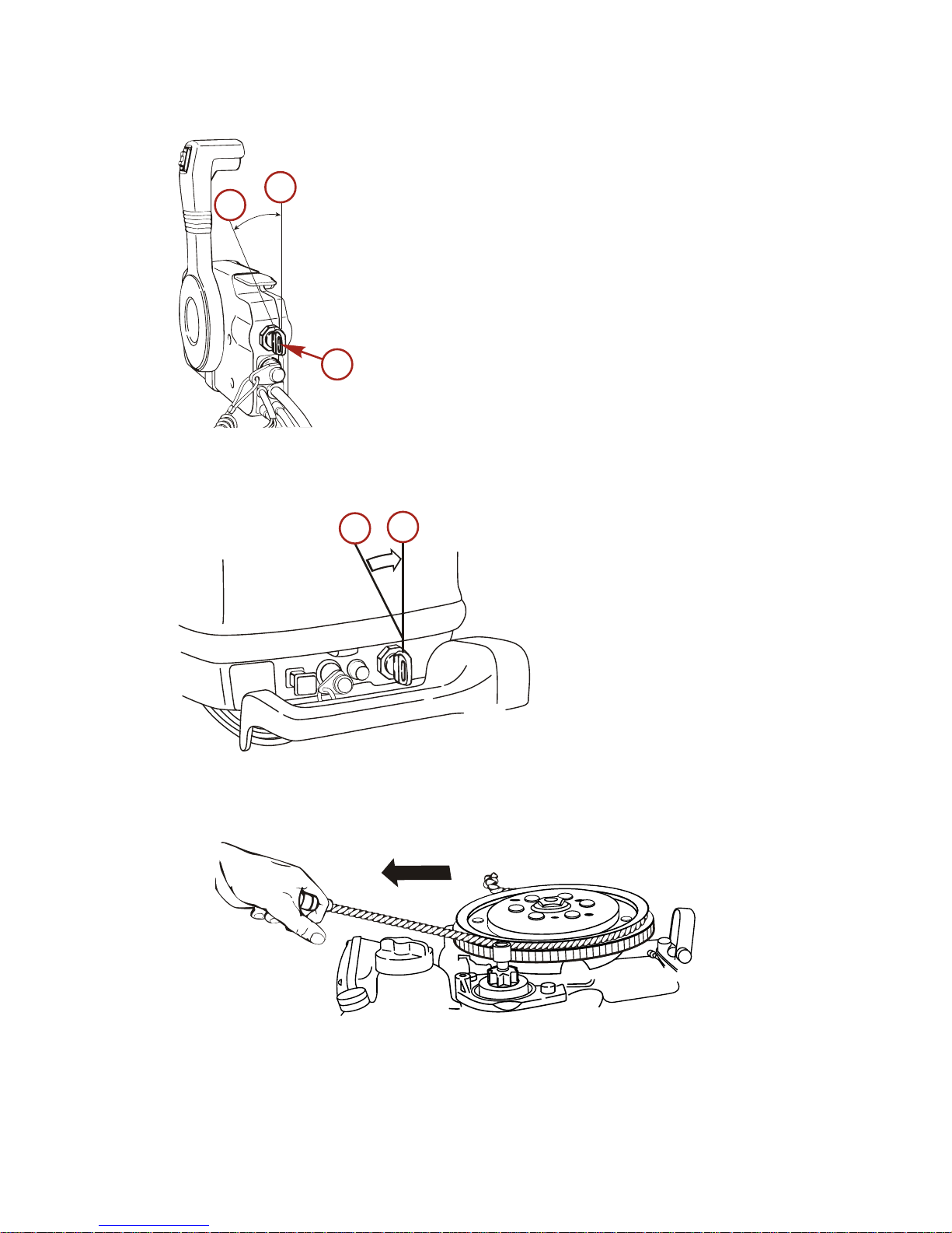
7. EO, EPTO: Turn the key switch to ON.
a - Off
b - On
c - Key switch
8. EH, EHO, EHPTO: Turn the key switch to ON.
a - Off
b - On
9. Wind the starter rope around the flywheel a few turns clockwise. Give it a
sharp tug to start the engine. Use a socket wrench to get a firm grip on
the end of the rope.
38361
10. Remote control models: Ensure the key switch is in the "ON" position.
NOTE: Confirm that the shift lever is in the Neutral (N) position.
37881
a
b
c
38359
a
b
OPERATION
eng 65
Page 76

WARM-UP
Before driving the boat, let the engine run at low speed for approximately three
minutes to let it warm‑up. If the engine is not warmed up beforehand, the
engine life will shorten greatly. During the warm‑up operation, confirm that
cooling water is discharged from the water pump indicator hole and idle port.
IMPORTANT: If cooling water is not discharged and engine operation is
continued, the engine may overheat and damage may occur.
a - Cooling water discharge
port
b - Idle port
Engine speed:
Proper idle speed after warm‑up operation
In‑gear
Neutral
750 RPM 900 RPM
Do not exceed the full‑throttle engine speed
Full throttle engine speed
40 50
5000–5700 RPM 5150–5850 RPM
OVERHEAT ALARM AND SENSOR (OPTIONAL ON SOME MODELS)
EH, EHO, EHPTO, EO, EPTO
• The overheat alarm will sound if the engine temperature exceeds the
preset level.
• If the alarm sounds indicating overheating, immediately move the remote
control lever to Neutral (N). Confirm that cooling water is discharged from
the water pump indicator hole, and then stop the engine. Turn the key
switch to "OFF" position.
• Remove dirt or other foreign matter clogging the water inlets on the
gearcase.
NOTE: If the alarm sounds frequently after restarting the engine, contact your
service dealer.
38362
a
b
OPERATION
66 eng
Page 77

NOTE: Check for a steady stream flowing out of the water pump indicator hole.
If no water is coming out of the water pump indicator hole or flow is intermittent,
stop the engine and check cooling water intake holes for obstruction. If no
obstruction is found, this may indicate a blockage in the cooling system or a
water pump problem. Have the outboard checked by your dealer. Operating the
engine while overheated may cause engine damage.
NOTE: Should overheating occur and you are stranded, stop the engine and
sllow it to cool down. This will usually allow some additional low speed (idle)
running time before the engine starts to overheat again. Operating an
overheated engine may cause engine damage.
NOTICE
Without sufficient cooling water, the engine, the water pump, and other
components will overheat and suffer damage. Provide a sufficient supply of
water to the water inlets during operation.
IMPORTANT: If a steady flow of water is coming out of the water pump
indicator hole and the engine continues to overheat, consult your dealer.
Stopping the Engine
IMPORTANT: Never stop the engine immediately after a full throttle run. Keep
it running for two or three minutes at idling speed (Neutral) to allow the engine
to cool down.
MH
1. Reduce the engine speed to idle RPM.
2. Pressing on the stop switch or pull the lanyard. The engine will then stop.
38368
EH, EHO, EHPTO
1. Reduce the engine speed to idle RPM.
OPERATION
eng 67
Page 78

2. Turn the main switch to OFF, press the stop switch or pull the lanyard.
The engine will then stop.
a - Lanyard/stop switch
EO, EPTO
1. Move the remote control lever to Neutral (N) and let the engine idle for
two or three minutes to allow it to cool down.
a - Neutral (N)
38369
a
39942
a
OPERATION
68 eng
Page 79

2. Turn the key switch counterclockwise to the OFF position or pull the
lanyard. The engine will then stop. The engine can also be stopped by
pressing on the lanyard switch.
a - Off
b - On
c - Stop switch lock plate
NOTE: Please follow the instructions below:
• Disconnect the fuel connector from the engine.
• After the engine has stopped, close the air vent screw on the fuel tank
cap.
• Disconnect the battery cables from the battery if the engine will not be
used for an extended period of time.
3. Disconnect the fuel connector from the engine.
38345
4. Close the air vent screw on the fuel tank cap.
a - Air vent screw
39943
a
b
c
38342
a
OPERATION
eng 69
Page 80

Cleaning Care Recommendations
OUTBOARD CARE
To keep your outboard in the best operating condition, it is important that your
outboard receive the periodic inspections and maintenance listed in the
Inspection and Maintenance Schedule. We urge you to keep it maintained
properly to ensure the safety of you and your passengers, and retain its
dependability.
Record maintenance performed in the Maintenance Log at the back of this
book. Save all maintenance work orders and receipts.
Selecting Replacement Parts For Your Outboard
We recommend using original Mercury Precision or Quicksilver replacement
parts and Genuine Lubricants.
DO NOT USE CAUSTIC CLEANING CHEMICALS
IMPORTANT: Do not use caustic cleaning chemicals on the outboard power
package. Some cleaning products contain strong caustic agents such as hull
cleaners with hydrochloric acid. These cleaners can degrade some of the
components they come in contact with including critical steering fasteners.
Damage to steering fasteners may not be obvious during visual inspection and
this damage may lead to catastrophic failure. Some caustic cleaning chemicals
may cause or accelerate corrosion. Exercise caution when using cleaning
chemicals around the engine and follow the recommendations on the
packaging of the cleaning product.
CLEANING GAUGES
IMPORTANT: Never use high‑pressure water to clean gauges.
Routine cleaning of the gauges is recommended to prevent a buildup of salt
and other environmental debris. Crystalized salt can scratch the gauge display
lens when using a dry or damp cloth. Ensure that the cloth has a sufficient
amount of fresh water to dissolve and remove salt or mineral deposits. Do not
apply aggressive pressure on the display lens while cleaning.
When water marks cannot be removed with a damp cloth, mix a 50/50 solution
of warm water and isopropyl alcohol to clean the display lens. Do not use
acetone, mineral spirits, turpentine type solvents, or ammonia based cleaning
products. The use of strong solvents or detergents may damage the coating,
the plastics, or the rubber keys on the gauges. If the gauge has a sun cover
available, it is recommended that the cover be installed when the unit is not in
use to prevent UV damage to the plastic bezels and rubber keys.
CLEANING REMOTE CONTROLS
IMPORTANT: Never use high‑pressure water to clean remote controls.
MAINTENANCE
70 eng
Page 81

Routine cleaning of the remote control external surfaces is recommended to
prevent a buildup of salt and other environmental debris. Use a cloth towel
which has a sufficient amount of fresh water to dissolve and remove salt or
mineral deposits.
When water marks cannot be removed with a damp cloth, mix a 50/50 solution
of warm water and isopropyl alcohol to clean the remote control. Do not use
acetone, mineral spirits, turpentine type solvents, or ammonia based cleaning
products. The use of strong solvents or detergents may damage the coating,
the plastics, or the rubber components on the remote control.
CLEANING CARE FOR TOP AND BOTTOM COWLS
IMPORTANT: Dry wiping (wiping the plastic surface when it is dry) will result in
minor surface scratches. Always wet the surface before cleaning. Do not use
detergents containing hydrochloric acid. Follow the cleaning and waxing
procedure.
Cleaning and Waxing Procedure
1. Before washing, rinse the cowls with clean water to remove dirt and dust
that may scratch the surface.
2. Wash the cowls with clean water and a mild nonabrasive soap. Use a soft
clean cloth when washing.
3. Dry thoroughly with a soft clean cloth.
4. Wax the surface using a nonabrasive automotive polish (polish designed
for clear coat finishes). Remove the applied wax by hand using a clean
soft cloth.
5. To remove minor scratches, use Mercury Marine Cowl Finishing
Compound (92‑859026K 1).
Inspection and Maintenance Schedule
DAILY CHECKS
• Check the engine oil level
• Check the lanyard stop switch
• Inspect the fuel system for leaks
• Inspect the engine tightness on the transom
• Check the steering system for binding
• Check the propeller for damage
• Inspect the hydraulic steering fittings and hoses for leaks or signs of
damage, if equipped
• Check the hydraulic steering fluid level, if equipped
AFTER EACH USE
• Wash the power package exterior with fresh water
• Flush the outboard cooling system, saltwater or brackish water only
MAINTENANCE
eng 71
Page 82

ANNUALLY OR 100 HOURS
• Grease the engine, if applicable
• Change the engine oil and filter, if equipped
• Inspect the thermostat, saltwater or brackish water only
• Add Quickleen to the fuel tank, once per year, per engine
• Apply antiseize to the spark plug threads
• Replace the gear lubricant
• Inspect the corrosion control anodes
• Lubricate the propeller shaft splines
• Replace all filters on the suction side of the fuel system—dealer item
• Lubricate the driveshaft splines—dealer item
• Check the tightness on all the fasteners—dealer item
• Check the torque of the outboard mounting hardware—dealer item
• Check the battery condition and tightness of the battery cable connection,
if equipped—dealer item
THREE YEARS OR 300 HOURS
• Replace the spark plugs
• Replace the water pump impeller—dealer item
• Inspect the carbon fiber reeds, if equipped—dealer item
• Inspect the wire harness connectors—dealer item
• Check the remote control cable adjustment, if equipped—dealer item
• Replace the high‑pressure fuel filter, if equipped—dealer item
• Replace the accessory drive belt, if equipped—dealer item
• Check the power trim fluid level, if equipped—dealer item
• Inspect the engine motor mounts—dealer item
Flushing the Cooling System
Flush the internal water passages of the outboard with fresh water after each
use in salt, polluted, or muddy water. This will help prevent a buildup of
deposits from clogging the internal water passages.
Use a Mercury Precision or Quicksilver accessory (or equivalent) flushing
attachment.
IMPORTANT: The engine must be run during flushing in order to open the
thermostat and circulate water through the water passages.
MAINTENANCE
72 eng
Page 83

!
WARNING
Rotating propellers can cause serious injury or death. Never operate the boat
out of the water with a propeller installed. Before installing or removing a
propeller, place the drive unit in neutral and engage the lanyard stop switch
to prevent the engine from starting. Place a block of wood between the
propeller blade and the anti‑ventilation plate.
1.
Remove the propeller. Refer to Propeller Replacement. Install the
flushing attachment so the rubber cups fit tightly over the cooling water
intake.
27256
Flushing Device 91‑44357Q 2
9192
Attaches to the water intakes; provides
a fresh water connection when flushing
the cooling system or operating the
engine.
2. Attach a water hose to the flushing attachment. Turn on the water and
adjust the flow so water is leaking around the rubber cups to ensure the
engine receives an adequate supply of cooling water.
27259
3. Start the engine and run it at idle speed in neutral shift position.
IMPORTANT: Do not run the engine above idle when flushing.
MAINTENANCE
eng 73
Page 84
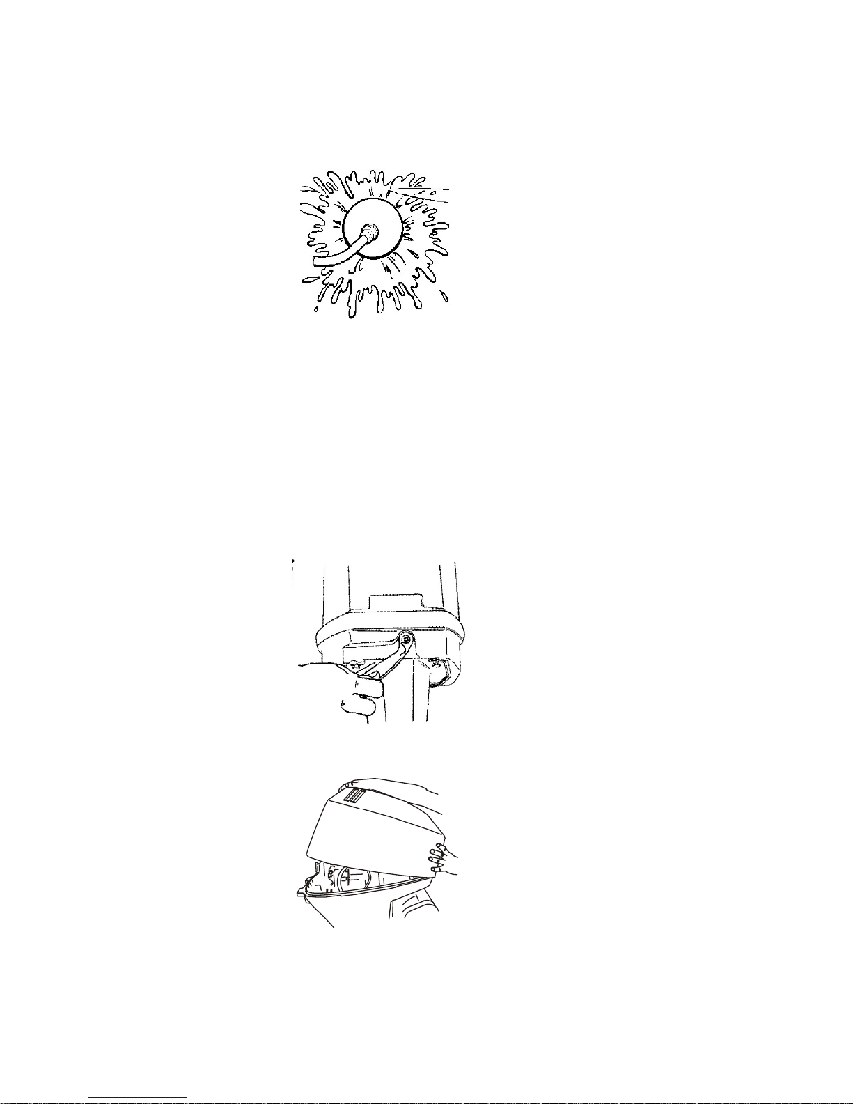
4. Adjust the water flow (if necessary) so excess water continues leaking out
from around the rubber cups to ensure the engine is receiving an
adequate supply of cooling water.
27260
5. Check for a steady stream of water flowing out of the water pump
indicator hole. Continue flushing the outboard for 3 to 5 minutes, carefully
monitoring water supply at all times.
6. Stop the engine, turn off the water, and remove the flushing attachment.
Install the propeller.
Top Cowl Removal and Installation
REMOVAL
1. Unlock the rear latch by pushing lever down.
29054
2. Lift rear of cowl and disengage front hook.
26851
INSTALLATION
1. Engage the front hook and push cowl back over the cowl seal.
MAINTENANCE
74 eng
Page 85

2. Push cowl down and move the rear latch lever up to lock.
Battery Inspection
The battery should be inspected at periodic intervals to ensure proper engine
starting capability.
IMPORTANT: Read the safety and maintenance instructions which accompany
your battery.
1. Turn off the engine before servicing the battery.
2. Ensure the battery is secure against movement.
3. Battery cable terminals should be clean, tight, and correctly installed.
Positive to positive and negative to negative.
4. Ensure the battery is equipped with a nonconductive shield to prevent
accidental shorting of battery terminals.
Fuel System
!
WARNING
Fuel is flammable and explosive. Ensure that the key switch is off and the
lanyard is positioned so that the engine cannot start. Do not smoke or allow
sources of spark or open flame in the area while servicing. Keep the work
area well ventilated and avoid prolonged exposure to vapors. Always check
for leaks before attempting to start the engine, and wipe up any spilled fuel
immediately.
Before servicing any part of the fuel system, stop the engine and disconnect
the battery. Drain the fuel system completely. Use an approved container to
collect and store fuel. Wipe up any spillage immediately. Material used to
contain spillage must be disposed of in an approved receptacle. Any fuel
system service must be performed in a well‑ventilated area. Inspect any
completed service work for sign of fuel leakage.
FUEL LINE INSPECTION
Visually inspect the fuel line and primer bulb for cracks, swelling, leaks,
hardness, or other signs of deterioration or damage. If any of these conditions
are found, the fuel line or primer bulb must be replaced.
ENGINE FUEL FILTER
Inspect the sight bowl for water accumulation and inspect the filter element for
sediment. Clean the tank and filters as follows.
CHECKING AND REFILLING OIL IN THE POWER TRIM AND TILT
1. Check the oil level of the reservoir tank, as shown, while the engine is
kept in a vertical position.
MAINTENANCE
eng 75
Page 86
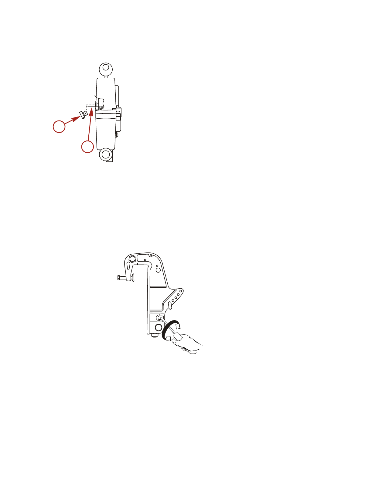
2. Remove the oil plug by turning counterclockwise, then check if the oil
level reaches the bottom line of the plug hole.
a - Oil cap
b - Oil level
NOTE: Do not fully unscrew the oil plug with the engine tilted down.
Pressurized oil in the oil tank may spurt out.
3. Recommended oil: Add Mercury or Quicksilver Power Trim and Steering
Fluid. If not available, use automotive automatic transmission fluid (ATF).
4. Air purging from the power trim and tilt unit: Entrapped air in the power
trim and tilt unit will cause poor tilting movement. With the engine
mounted on the boat, set the manual release valve to the manual side,
and tilt the engine manually up/down 5–6 times while checking the oil
level. When done, close the valve by turning towards the power side.
38382
CLEANING FUEL TANKS AND FILTERS
1. Water or dirt in the fuel tank may cause engine trouble.
2. Clean the tank at specified times or after a long storage period (over three
months).
Fuel filters are provided inside the fuel tank and at the engine.
38395
a
b
MAINTENANCE
76 eng
Page 87

1. Loosen a fuel pickup elbow and remove it. Then clean the fuel filter.
a - Fuel pickup elbow
b - Filter
2. Clean the fuel filter on the engine after removing the fuel filter cases.
a - Oil filter
b - Fuel filter
3. Oil filter and oil tank: Check the oil tank and/or filter for entrapped water
and dust.
a. Disconnect all hoses between the oil tank and oil pump.
b. Clean out all the foreign debris.
c. Refit the hoses to the oil tank and pumps, and fill up with new engine
oil.
d.
For air purging, refer to Fuel and Oil ‑ Oil pump air vent.
Fuse Replacement ‑ Electric Start Remote Control Models
IMPORTANT: Always carry spare SFE 20 amp fuses.
The electric starting circuit is protected from overload by an SFE 20 amp fuse.
If the fuse is blown, the electric starter motor will not operate. Try to locate and
correct the cause of the overload. If the cause is not found, the fuse may blow
again. Replace fuse with a fuse of the same rating.
39900
a
b
38393
a
b
MAINTENANCE
eng 77
Page 88

Corrosion Control Anode
Your outboard has a corrosion control anode installed on the gearcase and in
the cylinder. An anode helps protect the outboard against galvanic corrosion by
sacrificing its metal to be slowly corroded instead of the outboard metals.
The anode requires periodic inspection, especially in saltwater which will
accelerate the erosion. To maintain this corrosion protection, always replace
the anode before it is completely eroded. Never paint or apply a protective
coating on the anode, as this will reduce effectiveness of the anode.
a - Anode (trim tab)
Important:
•
Before replacing the anode, remove the spark plug cap to make sure
the engine will not start, then check and replace the anode.
•
If the anode is worn out or no anode is fitted on the outboard motor,
aluminum parts will corrode more rapidly which can cause paint to
peel off and damage the surface.
Propeller Replacement
!
WARNING
Rotating propellers can cause serious injury or death. Never operate the boat
out of the water with a propeller installed. Before installing or removing a
propeller, place the drive unit in neutral and engage the lanyard stop switch
to prevent the engine from starting. Place a block of wood between the
propeller blade and the anti‑ventilation plate.
REMOVING PROPELLER
1. Remote control model: Shift outboard to Neutral (N) position.
37879
a
MAINTENANCE
78 eng
Page 89

2. Tiller handle model: Move shift lever to Neutral (N) position.
38347
3. Remove the spark plug leads to prevent the engine from starting.
26899
4. Place a block of wood between the gearcase and propeller to hold the
propeller.
27296
MAINTENANCE
eng 79
Page 90
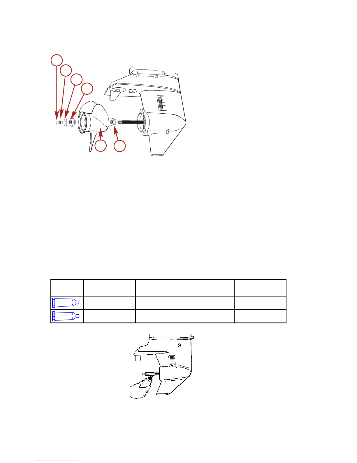
5. Remove the cotter pin, propeller nut, stopper, and washer.
a - Cotter pin
b - Nut
c - Washer
d - Stopper
e - Propeller
f - Propeller thrust holder
6. Pull propeller straight off the propeller shaft. If the propeller is seized to
the propeller shaft and cannot be removed, have the propeller removed
by an authorized dealer.
7. Coat the propeller shaft with Quicksilver or Mercury Precision Lubricants
Extreme Grease or 2‑4‑C with PTFE.
Tube Ref
No.
Description Where Used Part No.
Extreme Grease Propeller shaft 8M0071842
95
2-4-C with PTFE Propeller shaft 92-802859A 1
27344
38390
a
c
e
b
d
f
MAINTENANCE
80 eng
Page 91

IMPORTANT: To prevent the propeller hub from corroding and seizing to the
propeller shaft (especially in saltwater), always apply a coat of the
recommended lubricant to the entire propeller shaft at the recommended
maintenance intervals, and also each time the propeller is removed.
INSTALLING PROPELLER
1. Install the propeller thrust holder, propeller, washer, nut, stopper, and
cotter pin onto the propeller shaft.
a - Cotter pin
b - Nut
c - Washer
d - Stopper
e - Propeller
f - Propeller thrust holder
2. Place the propeller nut retainer over the pins. Place a block of wood
between the gearcase and propeller. Tighten the propeller nut to the
specified torque.
Description
Nm lb‑in. lb‑ft
Propeller nut 75 – 55
3. Install the spark plug leads.
Spark Plug Inspection and Replacement
!
WARNING
Damaged spark plug boots may emit sparks that can ignite fuel vapors under
the engine cowl, resulting in serious injury or death from a fire or explosion.
To avoid damaging the spark plug boots, do not use any sharp object or
metal tool to remove the spark plug boots.
38390
a
c
e
b
d
f
MAINTENANCE
eng 81
Page 92

1. Remove the spark plug boots. Twist the rubber boots slightly and pull off.
26899
2. Remove the spark plugs to inspect. Replace spark plug if electrode is
worn or the insulator is rough, cracked, broken, blistered, or fouled.
26946
3. Set the spark plug gap (0.9–1.0 mm).
26947
4. Before installing the spark plugs, clean off any dirt on the spark plug
seats. Install the plugs finger‑tight, and then tighten 1/4 turn or torque to
specifications.
Description
Nm lb‑in. lb‑ft
Spark plug 27 – 20
IMPORTANT: Please follow the instructions below:
• Do not touch the high tension cables running from the ignition coil to the
spark plugs while the engine is running or it is turned by the electric
starter motor, not even for testing the high tension cables or the spark
plugs.
• The high tension cables and the spark plugs generate very high electric
voltage, which can cause a serious electric shock if touched.
MAINTENANCE
82 eng
Page 93

Lubrication Points
It is important to inspect and maintain your outboard motor regularly.
Maintenance intervals should be determined according to the number of hours
or number of months, whichever comes first. For periodic servicing and
maintenance guidelines, please contact your local Mercury dealer.
Item
Every 50 hours or 3
months
Every 100 hours or
6 months
Action
Sliding and
rotating parts
Yes Yes
Apply and pump
in grease
Grease
fittings
Yes Yes
Apply and pump
in grease
Gearcase Lubricant
GEARCASE LUBRICATION
When adding or changing gearcase lubricant, visually check for the presence of
water in the lubricant. If water is present, it may have settled to the bottom and
will drain out prior to the lubricant, or it may be mixed with the lubricant, giving it
a milky colored appearance. If water is noticed, have the gearcase checked by
your dealer. Water in the lubricant may result in premature bearing failure or, in
freezing temperatures, will turn to ice and damage the gearcase.
Remove the fill/drain plug and examine the magnetic end for metal particles. A
small amount of metal filings or fine metal particles indicates normal gear wear.
An excessive amount of metal filings or larger particles (chips) may indicate
abnormal gear wear and should be checked by an authorized dealer.
CHANGING GEAR OIL
1. Place the outboard in a vertical operating position.
2. Place a drain pan below the outboard.
3. Remove the oil plugs (upper and lower) and drain the gear oil completely.
40/50
a - Vent plug
b - Fill plug
38391
a
b
MAINTENANCE
eng 83
Page 94

W50
a - Vent plug
b - Fill plug
4. Place the lubricant tube nozzle into the fill/drain hole and add the lubricant
until it appears at the upper oil plug hole.
40/50
a - Vent plug
b - Fill plug
c - Lubricant tube nozzle
W50
a - Vent plug
b - Fill plug
39897
b
a
38392
a
b
c
39898
b
a
MAINTENANCE
84 eng
Page 95

5. Install the vent plug. Then remove the lubricant tube nozzle and install the
fill plug.
40/50
a - Vent plug
b - Fill plug
W50
a - Vent plug
b - Fill plug
NOTE: Use only genuine or recommended gear oil. If not available, use an API
(American Petroleum Institute) oil grade of GL5 SAE #80–SAE #90.
Required volume
40/50 Approximation 500 mL 17 fl oz
W50 Approximation 700 mL 24 fl oz
GEARCASE LUBRICANT RECOMMENDATION
Mercury or Quicksilver Premium or High Performance Gear Lubricant.
Submerged Outboard
A submerged outboard will require service within a few hours by an authorized
dealer once the outboard is recovered from the water. This immediate attention
by a servicing dealer is necessary once the engine is exposed to the
atmosphere to minimize internal corrosion damage to the engine.
Following are the emergency measures to be taken on the submerged
outboard.
38391
a
b
39897
b
a
MAINTENANCE
eng 85
Page 96

1. Immediately take it out of the water and wash it with fresh water to
remove salt or dirt.
2. Remove the spark plugs and completely drain the water from the engine
by pulling the rewind starter several times.
3. Sufficiently inject genuine engine oil through the spark plug hole and into
the crankcase from the carburetor side. Pull the rewind starter several
times to circulate the oil throughout the motor.
MAINTENANCE
86 eng
Page 97

Storage Preparation
The major consideration in preparing your outboard for storage is to protect it
from rust, corrosion, and damage caused by freezing of trapped water.
The following storage procedures should be followed to prepare your outboard
for out of season storage or prolonged storage (two months or longer).
NOTICE
Without sufficient cooling water, the engine, the water pump, and other
components will overheat and suffer damage. Provide a sufficient supply of
water to the water inlets during operation.
FUEL SYSTEM
IMPORTANT: Gasoline containing alcohol (ethanol or methanol) can cause a
formation of acid during storage and can damage the fuel system. If the
gasoline being used contains alcohol, it is advisable to drain as much of the
remaining gasoline as possible from the fuel tank, remote fuel line, and engine
fuel system.
Fill the fuel tank and engine fuel system with treated (stabilized) fuel to help
prevent formation of varnish and gum. Proceed with the following instructions.
• Portable fuel tank ‑ Pour the required amount of gasoline stabilizer (follow
instructions on container) into the fuel tank. Tip fuel tank back and forth to
mix stabilizer with the fuel.
• Permanently installed fuel tank ‑ Pour the required amount of gasoline
stabilizer (follow instructions on container) into a separate container and
mix with approximately 1 liter (1 US qt) of gasoline. Pour this mixture into
the fuel tank.
• Remove the fuel filter sight bowl and empty contents in a suitable
container. Refer to Maintenance ‑ Fuel System for removal and
installation of filter. Add 3 cc (1/2 tsp) of gasoline stabilizer into the fuel
filter sight bowl and install.
• Place the outboard in water or connect flushing attachment for circulating
cooling water. Run the engine for 15 minutes at idle RPM to fill the engine
fuel system with stabilized fuel.
Protecting External Outboard Components
•
Lubricate all outboard components listed in Maintenance ‑ Inspection
and Maintenance Schedule.
• Touch up any paint nicks. See your dealer for touch‑up paint.
• Spray Quicksilver or Mercury Precision Lubricants Corrosion Guard on
external metal surfaces (except corrosion control anodes).
STORAGE
eng 87
Page 98

Tube Ref
No.
Description Where Used Part No.
120
Corrosion Guard External metal surfaces 92-802878 55
Protecting Internal Engine Components
NOTE: Make sure the fuel system has been prepared for storage. Refer to
Fuel
System
, preceding.
IMPORTANT: Refer to Maintenance ‑ Spark Plug Inspection and Replacement
for correct procedure for removing spark plug boots.
• Place the outboard in water or connect flushing attachment for circulating
cooling water. Start the engine and let it run in neutral to warm up.
• With engine running at fast idle, stop the fuel flow by disconnecting the
remote fuel line. When engine begins to stall, quickly spray Quicksilver or
Mercury Precision Lubricants Storage Seal into carburetor until engine
stops from lack of fuel.
• Remove the spark plugs and inject a five second spray of storage seal
around the inside of the cylinder.
• Rotate the flywheel manually several times to distribute the storage seal
in the cylinder. Reinstall spark plug.
Gearcase
•
Drain and refill the gearcase lubricant (refer to Gearcase Lubricant).
Positioning Outboard for Storage
Store outboard in an upright (vertical) position to allow water to drain out of the
outboard.
NOTICE
Storing the outboard in a tilted position can damage the outboard. Water
trapped in the cooling passages or rain water collected in the propeller
exhaust outlet in the gearcase can freeze. Store the outboard in the full down
position.
Battery Storage
• Follow the battery manufacturer's instructions for storage and charging.
• Remove the battery from the boat and check water level. Charge if
necessary.
• Store the battery in a cool, dry place.
• Periodically check the water level and charge the battery during storage.
Pre‑Season Check
Have your dealer check the engine before the season starts, or if you prefer, be
sure to check the following items yourself:
STORAGE
88 eng
Page 99

• Check the electrolyte level, and measure the voltage and specific gravity
of the battery.
Specific Gravity at 20 °C Terminal Voltage (V) Charge Condition
1.120 10.5 Fully discharged
1.160 11.1 1/4 charged
1.210 11.7 1/2 charged
1.250 12.0 3/4 charged
1.280 13.2 Fully charged
• Check that the battery is secure and the battery cables are installed
properly.
• Clean the engine oil filter.
• Purge air in the oil line connecting the oil tank to the oil pump.
• Check the shift and throttle function properly. Be sure to turn the propeller
shaft when checking the shift function or else the shift linkage may be
damaged.
STORAGE
eng 89
Page 100

Starter Motor Will Not Crank the Engine (Electric Start Models)
POSSIBLE CAUSES
• Remote control models ‑ Blown 20 amp fuse in the starting circuit. Refer
to Maintenance section.
• Outboard is not shifted to neutral position.
• Weak battery or battery connections are loose or corroded.
• Ignition key switch failure.
• Wiring or electrical connection faulty.
• Starter motor or starter solenoid failure.
Engine Will Not Start
POSSIBLE CAUSES
• Lanyard stop switch not in "RUN" position.
•
Incorrect starting procedure. Refer to Operation section.
• Old or contaminated gasoline.
•
Engine flooded. Refer to Operation section.
• Fuel is not reaching the engine.
a. Fuel tank is empty.
b. Fuel tank vent not open or restricted.
c. Fuel line is disconnected or kinked.
d. Primer bulb not squeezed.
e. Primer bulb check valve is faulty.
f.
Fuel filter is obstructed. Refer to Maintenance section.
g. Fuel pump failure.
h. Fuel tank filter obstructed.
• Ignition system component failure.
•
Spark plugs fouled or defective. Refer to Maintenance section.
Engine Runs Erratically
POSSIBLE CAUSES
•
Spark plugs fouled or defective. Refer to Maintenance section.
• Incorrect setup and adjustments.
• Fuel is being restricted to the engine.
•
Engine fuel filter is obstructed. Refer to Maintenance section.
• Fuel tank filter obstructed.
• Stuck anti‑siphon valve on built in fuel tank.
• Fuel line is kinked or pinched.
• Fuel pump failure.
TROUBLESHOOTING
90 eng
 Loading...