

Page 1

3.0 MPI ECT
and 3.0 TKS
Sterndrive Models
OPERATION &
MAINTENANCE
MANUAL
Page 2

Page 3
Welcome
You have selected one of the finest marine power packages available. It incorporates numerous design features to
ensure operating ease and durability.
With proper care and maintenance, you will enjoy using this product for many boating seasons. To ensure maximum
performance and carefree use, we ask that you thoroughly read this manual.
The Operation and Maintenance Manual contains specific instructions for using and maintaining your product. We
suggest that this manual remain with the product for ready reference whenever you are on the water.
Thank you for purchasing one of our products. We sincerely hope your boating will be pleasant!
Mercury Marine, Fond du Lac, Wisconsin, U.S.A.
Name / function:
John Pfeifer, President,
Mercury Marine
Read This Manual Thoroughly
IMPORTANT: If you do not understand any portion of this manual, contact your dealer. Your dealer can also provide a
demonstration of actual starting and operating procedures.
Notice
Throughout this publication, and on your power package, warnings, cautions, and notices, accompanied by the
8M0113856 1215 eng
International Hazard Symbol !, may be used to alert the installer and user to special instructions concerning a
particular service or operation that may be hazardous if performed incorrectly or carelessly. Observe them carefully.
These safety alerts alone cannot eliminate the hazards that they signal. Strict compliance with these special instructions
while performing the service, plus common sense operation, are major accident prevention measures.
WARNING
!
Indicates a hazardous situation which, if not avoided, could result in death or serious injury.
!
CAUTION
Indicates a hazardous situation which, if not avoided, could result in minor or moderate injury.
NOTICE
Indicates a situation which, if not avoided, could result in engine or major component failure.
IMPORTANT: Identifies information essential to the successful completion of the task.
NOTE: Indicates information that helps in the understanding of a particular step or action.
IMPORTANT: The operator (driver) is responsible for the correct and safe operation of the boat, the equipment aboard,
and the safety of all occupants aboard. We strongly recommend that the operator read this Operation and Maintenance
Manual and thoroughly understand the operational instructions for the power package and all related accessories before
the boat is used.
WARNING
!
The engine exhaust from this product contains chemicals known to the state of California to cause cancer, birth
defects or other reproductive harm.
3.0 MPI ECT and 3.0 TKS Sterndrive Models
The serial numbers are the manufacturer’s keys to numerous engineering details that apply to your Mercury Marine
power package. When contacting Mercury Marine about service, always specify model and serial numbers.
Descriptions and specifications contained herein were in effect at the time this was approved for printing. Mercury
Marine, whose policies are based on continuous improvement, reserves the right to discontinue models at any time or to
change specifications or designs without notice and without incurring obligation.
© 2015 Mercury Marine
Page 4

Warranty Message
The product you have purchased comes with a limited warranty from Mercury Marine; the terms of the warranty are set forth
in the Warranty Manual included with the product. The Warranty Manual contains a description of what is covered, what is not
covered, the duration of coverage, how to best obtain warranty coverage, important disclaimers and limitations of
damages, and other related information. Please review this important information.
Copyright and Trademark Information
© MERCURY MARINE. All rights reserved. Reproduction in whole or in part without permission is prohibited.
Alpha, Axius, Bravo One, Bravo Two, Bravo Three, Circle M with Waves Logo, K‑planes, Mariner, MerCathode, MerCruiser,
Mercury, Mercury with Waves Logo, Mercury Marine, Mercury Precision Parts, Mercury Propellers, Mercury Racing,
MotorGuide, OptiMax, Quicksilver, SeaCore, Skyhook, SmartCraft, Sport‑Jet, Verado, VesselView, Zero Effort, Zeus, #1 On the
Water and We're Driven to Win are registered trademarks of Brunswick Corporation. Pro XS is a trademark of Brunswick
Corporation. Mercury Product Protection is a registered service mark of Brunswick Corporation.
Identification Records
Please record the following applicable information:
MerCruiser
Engine Model and Horsepower Engine Serial Number
Transom Assembly Serial Number (Sterndrive) Gear Ratio Sterndrive Unit Serial Number
Transmission Model (Inboard) Gear Ratio Transmission Serial Number
Propeller Number Pitch Diameter
Hull Identification Number (HIN) Purchase Date
Boat Manufacturer Boat Model Length
Exhaust Gas Emissions Certification Number (Europe Only)
Page 5

TABLE OF CONTENTS
Section 1 - Getting to Know Your Power Package
Identification Information............................................................ 2
Identification........................................................................ 2
Engine Serial Number Decal.............................................. 2
Alpha Sterndrive Serial Number......................................... 3
Alpha Transom Serial Number........................................... 3
Lanyard Stop Switch.................................................................. 4
Keep the Lanyard Stop Switch and Lanyard Cord in Good
Operating Condition............................................................. 5
Instrumentation.......................................................................... 5
VesselView........................................................................... 5
SmartCraft Digital Instruments............................................. 5
System Link Digital Instruments........................................... 6
Remote Controls........................................................................ 6
Panel Mount Features.......................................................... 7
Console Mount Features...................................................... 7
Section 2 - On the Water
Safe Boating Recommendations............................................. 18
Carbon Monoxide Exposure.................................................... 19
Be Alert To Carbon Monoxide Poisoning........................... 19
Stay Clear of Exhaust Areas.............................................. 19
Good Ventilation ................................................................ 19
Poor Ventilation ................................................................. 20
Launching and Boat Operation................................................ 20
Operation Chart.................................................................. 20
Starting and Stopping the Engine—3.0 MPI ECT.................... 21
Starting and Stopping the Engine..................................... 21
Starting the Engine....................................................... 21
Stopping the Engine..................................................... 21
Starting the Engine After Stopped While in Gear............. 21
Starting and Stopping the Engine—3.0 TKS............................ 21
Starting and Stopping the Engine..................................... 21
Starting the Engine....................................................... 21
Stopping the Engine..................................................... 22
Starting the Engine After It Has Been Stopped While In
Gear.................................................................................. 22
Throttle Only Operation............................................................ 22
Trailering the Boat.................................................................... 22
Freezing Temperature Operation............................................. 22
Drain Plug and Bilge Pump...................................................... 22
Protecting People in the Water................................................ 23
While You Are Cruising...................................................... 23
Power Trim................................................................................. 8
Single Engine Trim/Trailer.................................................... 9
Dual Engine Trim/Trailer...................................................... 9
Electrical System Overload Protection—3.0 MPI ECT.............. 9
Electrical System Overload Protection—3.0 TKS.................... 12
Visual and Audio Warning Systems (ECT).............................. 15
Service Engine Light and OBD‑M MIL Kit......................... 15
Testing the OBD‑M Malfunction Indicator Lamp (MIL). 15
Audio Warning System..................................................... 15
Caution......................................................................... 15
Critical...........................................................................15
Testing the Audio Warning System.............................. 15
Guardian Strategy............................................................. 16
Audio Warning System—3.0 TKS............................................ 16
Testing The Audio Warning System................................... 16
While Boat Is Stationary..................................................... 23
High‑Speed and High‑Performance Operation........................ 23
Passenger Safety in Pontoon Boats and Deck Boats.............. 23
Boats Having an Open Front Deck.....................................23
Boats With Front‑Mounted, Raised Pedestal Fishing Seats
........................................................................................... 23
Wave and Wake Jumping........................................................ 24
Impact with Underwater Hazards............................................. 24
Drive Unit Impact Protection...............................................25
Conditions Affecting Operation................................................ 25
Weight Distribution (Passengers and Gear) Inside the
Boat.................................................................................. 25
The Bottom of the Boat..................................................... 25
Cavitation.......................................................................... 25
Ventilation......................................................................... 25
Elevation and Climate....................................................... 26
Propeller Selection............................................................ 26
Getting Started—3.0 MPI ECT................................................. 26
20‑Hour Break‑In Period................................................... 26
After Break‑In Period........................................................ 26
End of First Season Checkup........................................... 27
Getting Started—3.0 TKS........................................................ 27
20‑Hour Break‑In Period................................................... 27
After Break‑In Period........................................................ 27
End of First Season Checkup........................................... 27
Section 3 - Specifications
Specifications—3.0 MPI ECT................................................... 30
Engine Specifications—3.0 MPI ECT............................... 30
Fuel Requirements........................................................... 30
Fuel Ratings................................................................. 30
Using Reformulated (Oxygenated) Gasoline (USA
Only)............................................................................. 30
Gasoline Containing Alcohol........................................ 31
90-8M0113856 eng DECEMBER 2015 Page i
Specifications—3.0 TKS.......................................................... 32
Bu16 Butanol Fuel Blends......................................... 31
Methanol and Ethanol Fuel Blends............................ 31
Engine Oil......................................................................... 31
Fluid Specifications........................................................... 32
Sterndrives................................................................... 32
Engine.......................................................................... 32
Page 6

Engine Specifications—3.0 TKS..................................... 32
Fuel Requirements.......................................................... 33
Fuel Ratings................................................................ 33
Using Reformulated (Oxygenated) Gasolines (USA
Only)............................................................................33
Section 4 - Maintenance
Gasolines Containing Alcohol..................................... 33
Engine Oil........................................................................ 34
Fluid Specifications......................................................... 34
Sterndrives.................................................................. 34
Engine......................................................................... 34
General Information................................................................ 38
Owner/Operator Responsibilities..................................... 38
Dealer Responsibilities.................................................... 38
Maintenance.................................................................... 38
Do‑It‑Yourself Maintenance Suggestions........................ 38
Inspection........................................................................ 39
Sealed Carburetor Mixture Screw................................... 39
Maintenance Schedules—3.0 MPI ECT................................. 39
Routine Maintenance...................................................... 39
Scheduled Maintenance.................................................. 40
Scheduled Maintenance Procedures Specifically for 3.0 MPI
ECT........................................................................................ 41
Cleaning the Flame Arrestor........................................... 41
Cleaning the IAC Muffler................................................. 41
Inspecting the Fuel Pump Sight Tube............................. 42
Drive Belts....................................................................... 43
Checking..................................................................... 43
Replacing Belts on Front Mount Models..................... 43
Power Steering Pump Drive Belt.............................. 43
Alternator Belt.......................................................... 43
Replacing Belts on Side Mount Models...................... 44
Power Steering Pump Drive Belt.............................. 44
Alternator Belt.......................................................... 44
Maintenance Schedules—3.0 TKS......................................... 44
Routine Maintenance...................................................... 44
Scheduled Maintenance.................................................. 45
Scheduled Maintenance Procedures Specifically for 3.0
TKS......................................................................................... 46
Cleaning the Flame Arrestor........................................... 46
Positive Crankcase Ventilation Valve (PCV)............... 47
Changing.................................................................. 47
Fuel Pump Sight Tube Inspection................................... 47
Drive Belts....................................................................... 48
Checking..................................................................... 48
Replacing ‑ Front Mount Models................................. 48
Power Steering Pump Drive Belt, if equipped.......... 48
Alternator Belt.......................................................... 48
Replacing ‑ Side Mount Models.................................. 49
Power Steering Pump Drive Belt, if equipped.......... 49
Alternator Belt.......................................................... 49
Changing the Water‑Separating Fuel Filter............................ 49
Engine Oil—3.0 MPI ECT....................................................... 50
Checking and Filling........................................................ 50
Changing the Oil and Filter.............................................. 51
Engine Oil—3.0 TKS.............................................................. 52
Checking and Filling........................................................ 52
Changing the Oil and Filter.............................................. 52
Power‑Assisted Steering Fluid—3.0 MPI ECT....................... 53
Checking......................................................................... 53
Filling............................................................................... 53
Changing......................................................................... 54
Power‑Assisted Steering Fluid—3.0 TKS............................... 54
Checking........................................................................... 54
Filling................................................................................ 54
Changing.......................................................................... 54
Engine Coolant—3.0 MPI ECT............................................... 55
Checking......................................................................... 55
Filling............................................................................... 56
Changing ........................................................................ 56
Engine Coolant—3.0 TKS...................................................... 56
Checking........................................................................... 56
Filling................................................................................ 57
Changing ......................................................................... 57
Alpha Sterndrive Gear Lube................................................... 57
Checking........................................................................... 57
Filling................................................................................ 58
Changing.......................................................................... 59
Power Trim Fluid.................................................................... 60
Checking........................................................................... 60
Filling................................................................................ 60
Changing.......................................................................... 61
Lubrication.............................................................................. 61
Steering System.............................................................. 61
Throttle Cable—3.0 MPI ECT.......................................... 62
Throttle Cable—3.0 TKS................................................. 63
Shift Plate Control Cable Lubrication.............................. 63
Driveshaft U‑joint Splines and O‑Rings (Sterndrive Unit
Removed)........................................................................ 64
Engine Coupler................................................................ 64
Driveshaft Extension Models........................................... 64
Propellers............................................................................... 65
Propeller Repair.............................................................. 65
Alpha Propeller Removal................................................. 65
Alpha Propeller Installation.............................................. 65
Flushing the Power Package.................................................. 66
Flushing Attachments....................................................... 66
Sterndrive Water Pickups................................................. 67
Battery.................................................................................... 68
Corrosion Protection............................................................... 68
Painting Your Power Package.......................................... 72
Section 5 - Storage
Cold Weather or Extended Storage........................................ 74
Reformulated (Oxygenated) Gasolines (U.S.A. Only)..... 74
Fuel Containing Alcohol.................................................. 74
Preparing Power Package for Storage—MPI Models..... 74
Special Fuel Mix.......................................................... 75
Page ii 90-8M0113856 eng DECEMBER 2015
Engine and Fuel System Preparation......................... 75
Preparing Power Package for Storage—Carburetor
Models............................................................................. 76
Engine and Fuel System Preparation......................... 76
Draining the Seawater System............................................... 77
Page 7

Draining the 3.0 MPI ECT Seawater System........................... 77
Single‑Point Drain System................................................ 77
Draining the Seawater Section of Models with Closed
Cooling.............................................................................. 78
Draining the 3.0 TKS Seawater System.................................. 80
Single Point Drain System................................................ 80
Section 6 - Troubleshooting
Draining the Seawater Section of Models With Closed
Cooling.............................................................................. 81
Clearing Clogged Blue Drain Hoses........................................ 83
Draining the Sterndrive............................................................ 85
Battery Storage........................................................................ 85
Recommissioning the Power Package.................................... 85
Troubleshooting Information and Charts Specifically for 3.0 MPI
ECT.......................................................................................... 88
Diagnosing EFI Problems................................................. 88
Engine Guardian System.................................................. 88
Starter Motor Will Not Crank Engine, or Cranks Slowly.... 88
Engine Will Not Start or Is Hard to Start........................... 88
Engine Runs Rough, Misses, or Backfires....................... 89
Poor Performance............................................................. 89
Troubleshooting Charts Specifically for 3.0 TKS..................... 89
Starter Motor Will Not Crank Engine, or Cranks Slow...... 89
Engine Will Not Start or Is Hard to Start........................... 89
Engine Runs Rough, Misses, or Backfires....................... 90
Poor Performance............................................................. 90
Section 7 - Customer Assistance Information
Owner Service Assistance....................................................... 94
Local Repair Service.......................................................... 94
Service Away From Home..................................................94
Stolen Power Package....................................................... 94
Attention Required After Submersion................................. 94
Replacement Service Parts................................................ 94
Parts and Accessories Inquiries................................... 94
Resolving a Problem.......................................................... 94
Troubleshooting Charts for 3.0 MPI ECT and 3.0 TKS............ 90
Excessive Engine Temperature........................................ 90
Insufficient Engine Temperature....................................... 91
Low Engine Oil Pressure.................................................. 91
Battery Will Not Recharge................................................ 91
Remote Control Is Difficult to Move, Has Excessive Play, or
Makes Unusual Sounds.................................................... 91
Steering Wheel Jerks or Is Difficult to Turn...................... 91
Power Trim Does Not Operate (Motor Does Not
Operate)............................................................................ 91
Power Trim Does Not Operate (Motor Operates but
Sterndrive Unit Does Not Move)....................................... 92
Contact Information for Mercury Marine Customer Service
........................................................................................... 95
Customer Service Literature.................................................... 95
English Language.............................................................. 95
Other Languages................................................................96
Ordering Literature................................................................... 96
United States and Canada................................................. 96
Outside the United States and Canada.............................. 96
Section 8 - Checklists
Predelivery Inspection (PDI).................................................... 98 Customer Delivery Inspection (CDI)........................................ 99
Section 9 - Maintenance Log
Scheduled Maintenance Log................................................. 102 Vessel Maintenance Notes.................................................... 103
90-8M0113856 eng DECEMBER 2015 Page iii
Page 8

Page iv 90-8M0113856 eng DECEMBER 2015
Page 9

Section 1 - Getting to Know Your Power Package
Section 1 - Getting to Know Your Power Package
Table of Contents
Identification Information........................................................ 2
Identification.....................................................................2
Engine Serial Number Decal........................................... 2
Alpha Sterndrive Serial Number...................................... 3
Alpha Transom Serial Number........................................ 3
Lanyard Stop Switch............................................................... 4
Keep the Lanyard Stop Switch and Lanyard Cord in
Good Operating Condition .............................................. 5
Instrumentation....................................................................... 5
VesselView ..................................................................... 5
SmartCraft Digital Instruments ....................................... 5
System Link Digital Instruments ..................................... 6
Remote Controls..................................................................... 6
Panel Mount Features .................................................... 7
Console Mount Features ................................................ 7
Power Trim............................................................................. 8
1
Single Engine Trim/Trailer .............................................. 9
Dual Engine Trim/Trailer ................................................. 9
Electrical System Overload Protection—3.0 MPI ECT........... 9
Electrical System Overload Protection—3.0 TKS................. 12
Visual and Audio Warning Systems (ECT)........................... 15
Service Engine Light and OBD‑M MIL Kit......................15
Testing the OBD‑M Malfunction Indicator Lamp (MIL)
.............................................................................. 15
Audio Warning System.................................................. 15
Caution .................................................................. 15
Critical ................................................................... 15
Testing the Audio Warning System ....................... 15
Guardian Strategy..........................................................16
Audio Warning System—3.0 TKS........................................ 16
Testing The Audio Warning System ............................. 16
90-8M0113856 eng DECEMBER 2015 Page 1
Page 10
Section 1 - Getting to Know Your Power Package
32121
a
b
c
32636
Identification Information
Identification
The serial numbers are the manufacturer's keys to numerous engineering details which apply to your MerCruiser power
package. When contacting MerCruiser about service, always specify model and serial numbers.
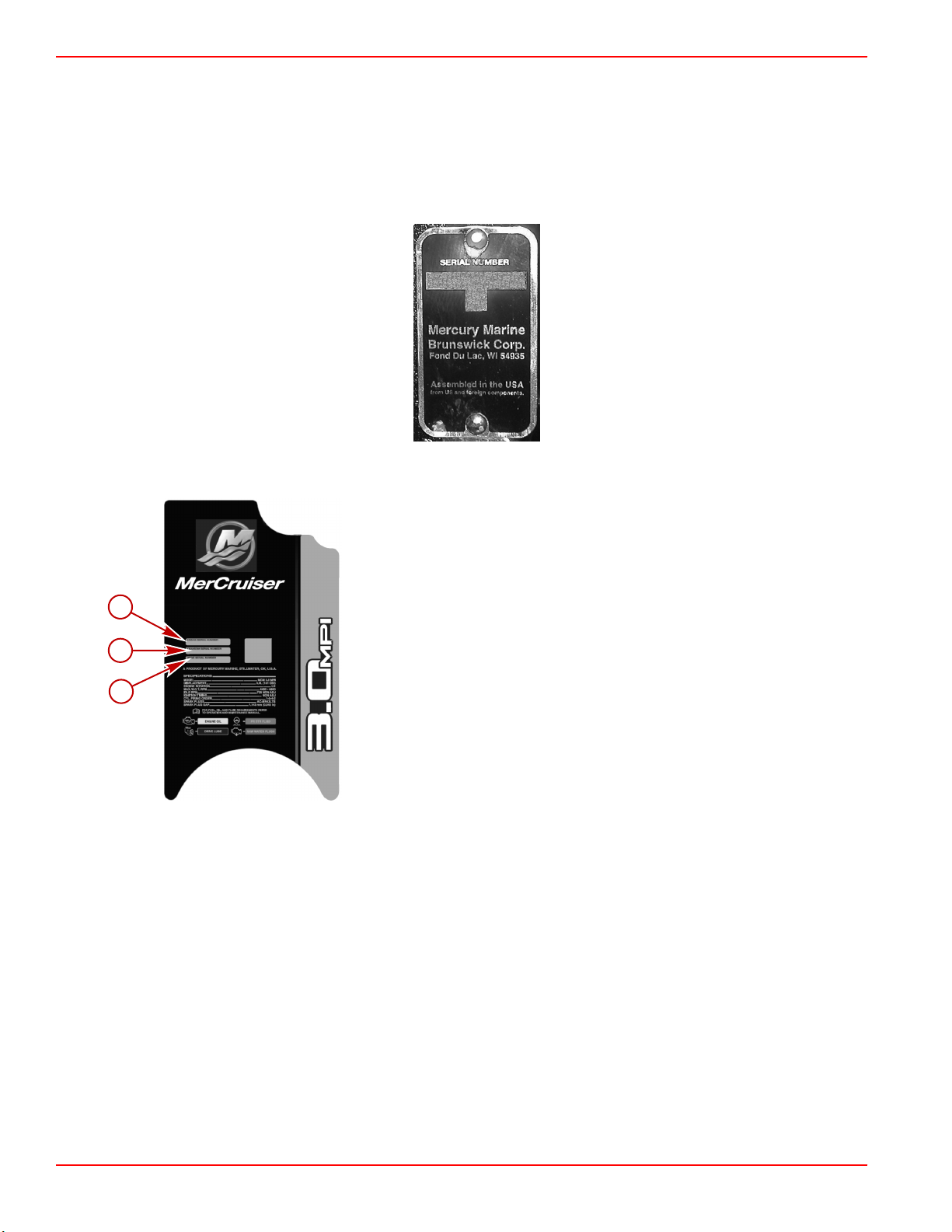
Engine Serial Number Decal
The serial number decal is located on the aft portion of the starboard side of the block, near the starter motor.
The engine, transom, and drive serial numbers are also located on the engine identification plate.
a - Engine serial number
b - Transom serial number
c - Drive serial number
Page 2 90-8M0113856 eng DECEMBER 2015
Page 11
Section 1 - Getting to Know Your Power Package
54406
Transom Serial No.
53651
44425
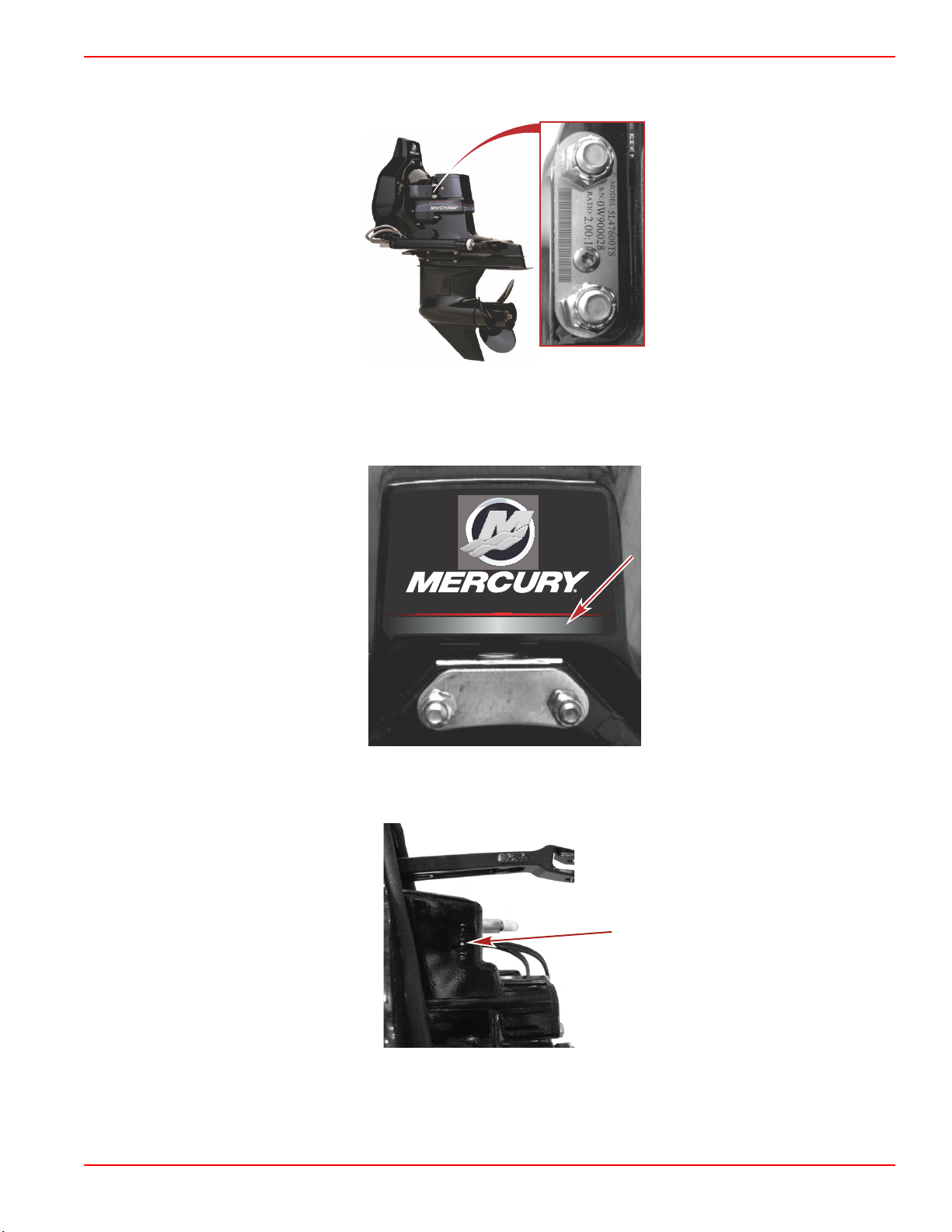
Alpha Sterndrive Serial Number
The drive serial number and the drive ratio are located on the port side of the sterndrive.
Alpha sterndrive
Alpha Transom Serial Number
The Alpha transom serial number is stamped in the transom assembly decal.
The serial number is also stamped on the gimbal housing. This is used as a permanent reference for authorized MerCruiser
dealers.
Serial number location on gimbal housing
90-8M0113856 eng DECEMBER 2015 Page 3
Page 12
Section 1 - Getting to Know Your Power Package
c
a
b
53910
OFF
RUN
ATTACH LANYARD
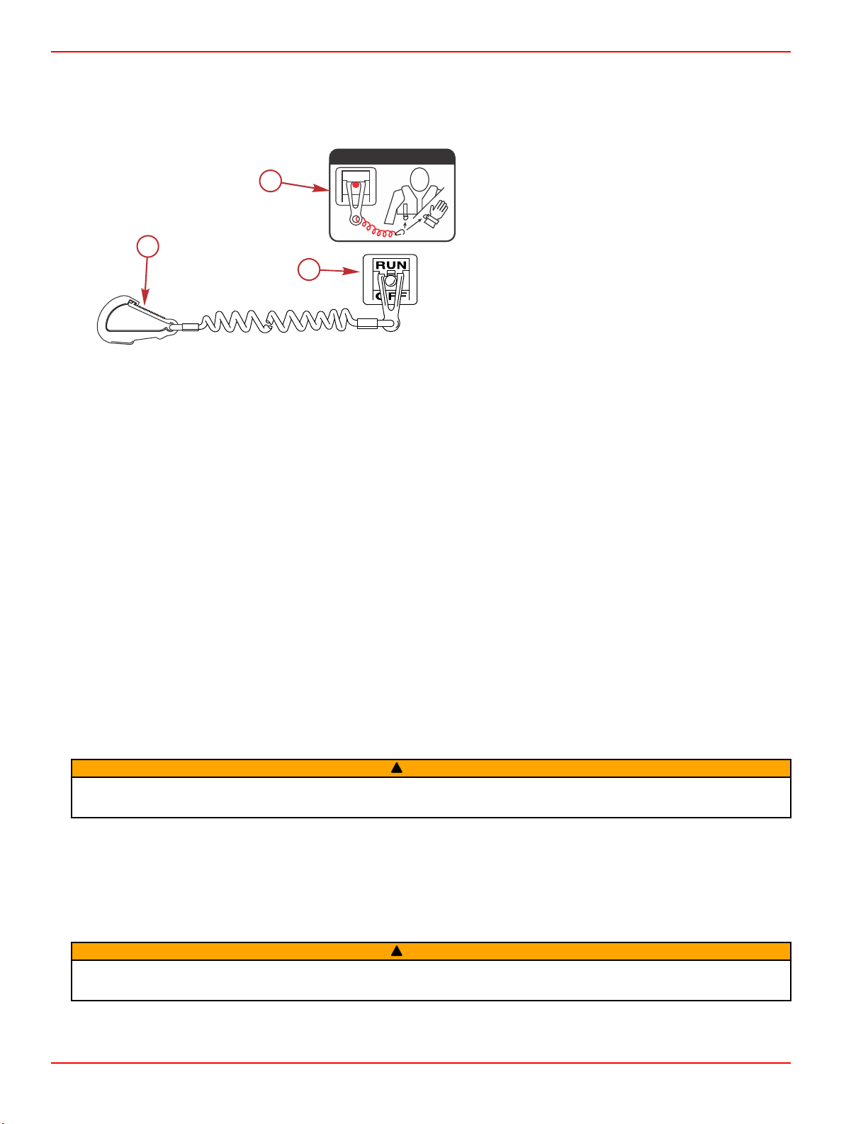
Lanyard Stop Switch
A lanyard switch is designed to shut down the engine in the event the operator unexpectedly moves away from the helm, as
may happen in an accidental ejection. The lanyard is connected to the operator's personal flotation device or wrist.
A decal near the lanyard stop switch reminds the operator to attach the lanyard to his or her personal flotation device or wrist.
a - Lanyard cord clip
b - Lanyard decal
c - Lanyard stop switch
Accidental ejections, such as falling overboard, are more likely to occur in:
• Low‑sided sport boats
• Bass boats
• High‑performance boats
Accidental ejections can also occur from:
• Poor operating practices
• Sitting on the seat or gunwale at planing speeds
• Standing at planing speeds
• Operating at planing speeds in shallow or obstacle‑infested waters
• Releasing your grip on the steering wheel
• Carelessness caused by consuming alcohol or drugs
• High‑speed boating maneuvers
The lanyard is a cord usually between 122 and 152 cm (4 and 5 ft) long when stretched out, with an element on one end made
to be inserted into the switch, and a snap on the other end for attaching to the operator. The lanyard is coiled to make its at‑rest
condition as short as possible to minimize the likelihood of lanyard entanglement with nearby objects. Its stretched‑out length is
made to minimize the likelihood of accidental activation should the operator choose to move around in an area close to the
operator's normal position. The operator can shorten the lanyard by wrapping the lanyard around his wrist, or by tying a knot in
the lanyard.
Activation of the lanyard stop switch will stop the engine immediately, but the boat will continue to coast for some distance,
depending upon its velocity. While the boat is coasting, it can cause injury to anyone in the boat's path as it would under power.
Instruct all passengers on the proper starting and operating procedures should they be required to operate the boat in an
emergency.
WARNING
!
If the operator falls out of the boat, stop the engine immediately to reduce the possibility of serious injury or death from being
struck by the boat. Always properly connect the operator to the stop switch using a lanyard.
Accidental or unintended activation of the switch during normal operation is also a possibility. This could cause any, or all, of
the following potentially hazardous situations:
• Occupants could be thrown forward due to unexpected loss of forward motion, a particular concern for passengers in the
front of the boat who could be ejected over the bow and possibly struck by the propulsion or steering components.
• Loss of power and directional control in heavy seas, strong current, or high winds.
• Loss of control when docking.
Avoid serious injury or death from deceleration forces resulting from accidental or unintended stop switch activation. The boat
operator should never leave the operator's station without first disconnecting the stop switch lanyard from the operator.
WARNING
!
Page 4 90-8M0113856 eng DECEMBER 2015
Page 13
Section 1 - Getting to Know Your Power Package
56038
Keep the Lanyard Stop Switch and Lanyard Cord in Good Operating Condition
Before each use, ensure that the lanyard stop switch works properly. Start the engine, and then stop it by pulling the lanyard
cord. If the engine does not stop, have the switch repaired before operating the boat.
Before each use, inspect the lanyard cord to ensure that it is in good working condition and that there are no breaks, cuts, or
wear to the cord. Check that the clips on the ends of the cord are in good condition. Replace any damaged or worn lanyard
cords.
Instrumentation
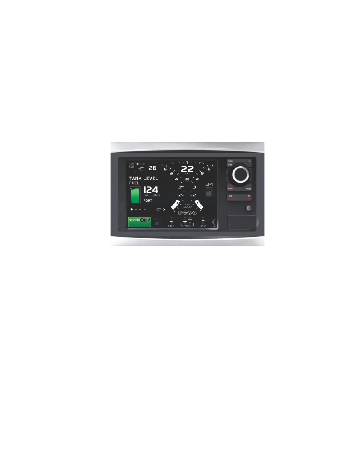
VesselView
There are several VesselView products available. VesselView will display all engine information, fault codes, vessel
information, basic navigation data, and system information. When an operating system error or failure occurs, VesselView
displays an alarm message.
VesselView may also be connected to other vessel systems such as GPS, generators, and chartplotters. This vessel
integration allows the operator to monitor and control a wide range of vessel systems from a single display.
Refer to the VesselView operator's manual for more information.
VesselView 7
SmartCraft Digital Instruments
The SmartCraft instrument package augments the VesselView display. The instrument package may include:
• Tachometer
• Speedometer
• Engine coolant temperature
• Engine oil pressure
• Battery voltage
• Fuel consumption
90-8M0113856 eng DECEMBER 2015 Page 5
Page 14
Section 1 - Getting to Know Your Power Package
abc
d
37925
a
b
c
c
50400
• Engine operating hours
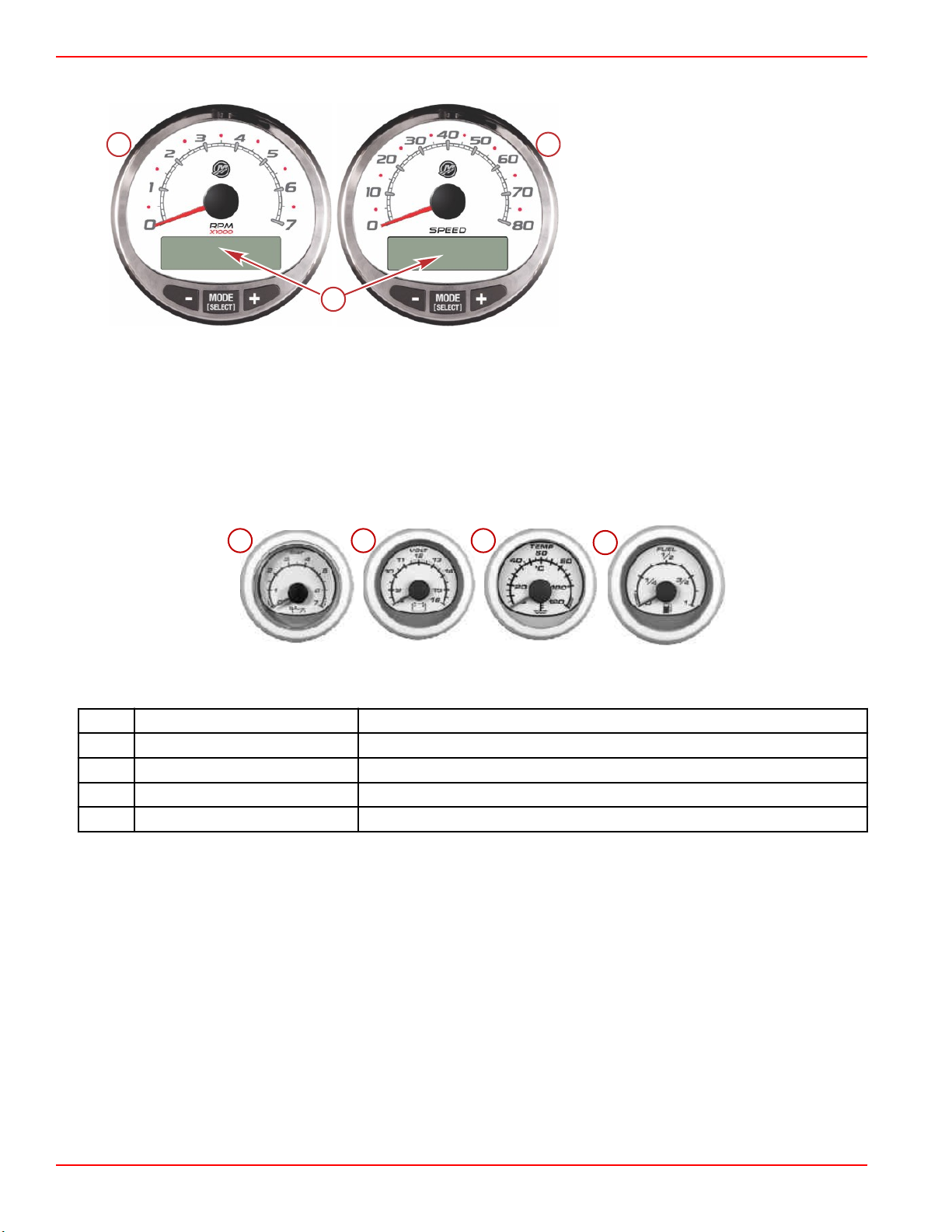
SmartCraft tachometer and speedometer
a - Tachometer
b - Speedometer
c - LCD display
The SmartCraft instrument package also aids in identifying fault codes associated with the engine audio warning system. The
SmartCraft instrument package displays critical engine alarm data and other potential problems on its LCD display.
For basic operation information on the SmartCraft instrument package and for details on the warning functions monitored by the
system, refer to the manual provided with your gauge package.
System Link Digital Instruments
Some instrumentation packages include system link gauges that augment the information provided by VesselView or a
SmartCraft system tachometer and speedometer. The owner and operator should be familiar with all the instruments and their
functions on the boat. Have your boat dealer explain the gauges and normal readings that appear on your boat.
The following digital instruments may be included with your power package.
System Link digital gauges
Item Gauge Indicates
a Oil pressure gauge Engine oil pressure
b Voltmeter Battery voltage
c Water temperature gauge Engine operating temperature
d Fuel gauge Quantity of fuel in tank
Remote Controls
Your boat may be equipped with Mercury Precision Parts or Quicksilver remote controls. All controls may not have all features
shown. Consult your dealer for a description and/or demonstration of your remote control.
Page 6 90-8M0113856 eng DECEMBER 2015
Page 15
Panel Mount Features
Section 1 - Getting to Know Your Power Package
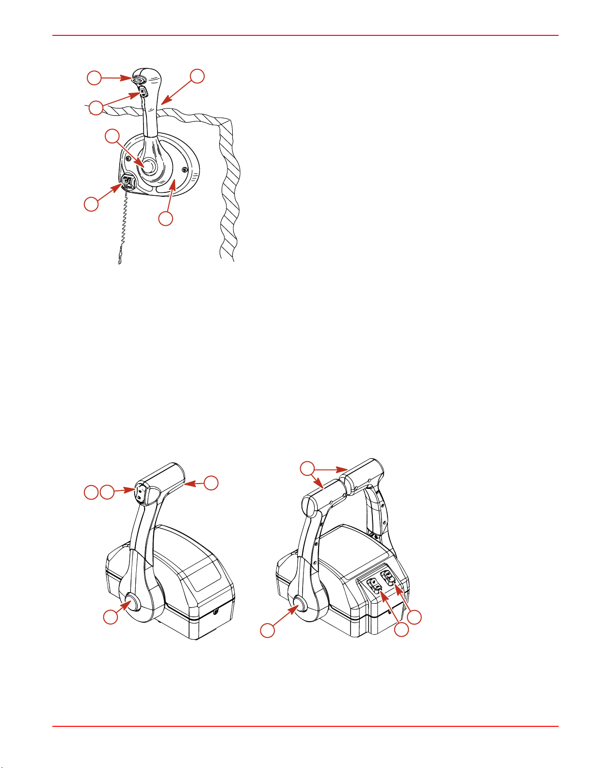
a
f
b
e
a - Neutral lock button
b - Throttle only button
c - Lanyard stop switch
d - Control handle tension adjustment screw
e - Control handle
f - Trim/tilt button
c
d
mc77019-1
Neutral lock button ‑ Prevents accidental shift and throttle engagement. Neutral lock button must be pushed into move the
control handle out of neutral.
Throttle only button ‑ Allows engine throttle advancement without shifting the engine. This is done by disengaging the shift
mechanism from the control handle. The throttle only button can be depressed only when the remote control handle is in the
neutral position, and should only be used to assist in starting the engine.
Lanyard stop switch ‑ Turns the ignition off whenever the operator (when attached to the lanyard) moves far enough away
from the operator's position to activate the switch. Refer to Lanyard Stop Switch for information on the use of this switch.
Control handle ‑ Operation of the shift and throttle are controlled by the movement of the control handle. Push the control
handle forward from neutral with a quick firm motion to the first detent for forward gear. Continue pushing forward to increase
speed. Pull the control handle back from neutral with a quick firm motion to the first detent for reverse gear and continue
pushing back to increase speed.
Control handle tension adjustment screw (not visible) ‑ This screw is used to adjust the effort required to move the remote
control handle. Refer to instructions provided with remote control for complete adjustment instructions.
Trim/tilt button ‑ Refer to Power Trim.
Console Mount Features
b
b
c
d
a
a
Throttle only button ‑ Allows engine throttle advancement without shifting the engine. This is done by disengaging the shift
mechanism from the control handle. The throttle only button can be depressed only when the remote control handle is in the
neutral position.
c
d
mc79503-1
a - Throttle only button
b - Control handle
c - Power trim switch
d - Trailer switch
90-8M0113856 eng DECEMBER 2015 Page 7
Page 16
Section 1 - Getting to Know Your Power Package
Control handles ‑ Operation of the shift and throttle are controlled by the movement of the control handle. Push the control
handle forward from neutral with a quick firm motion to the first detent for forward gear and continue pushing forward to
increase speed. Pull the control handle back from neutral with a quick firm motion to the first detent for reverse gear and
continue pushing back to increase speed.
Control handle tension adjustment screw (not visible) ‑ This screw is used to adjust the effort required to move the remote
control handle. Refer to instructions provided with remote control for complete adjustment instructions.
Power trim switch ‑ See Power Trim section for detailed power trim operating procedures.
Trailer switch ‑ Used to raise drive unit for trailering, launching, beaching or shallow water operation. See Power Trim for
detailed trailer switch operation.
Power Trim
Power trim allows the operator to adjust the sterndrive angle while underway, to provide the ideal boat angle for varying load
and water conditions. Also, the trailering feature allows the operator to raise and lower the sterndrive unit for trailering,
beaching, launching, low speed (below 1200 RPM engine speed), and shallow water operation.
WARNING
!
Excessive trim can cause serious injury or death at high speeds. Use caution when trimming the sterndrive, and never trim
out beyond the gimbal ring support flanges while the boat is underway or at engine speeds above 1200 RPM.
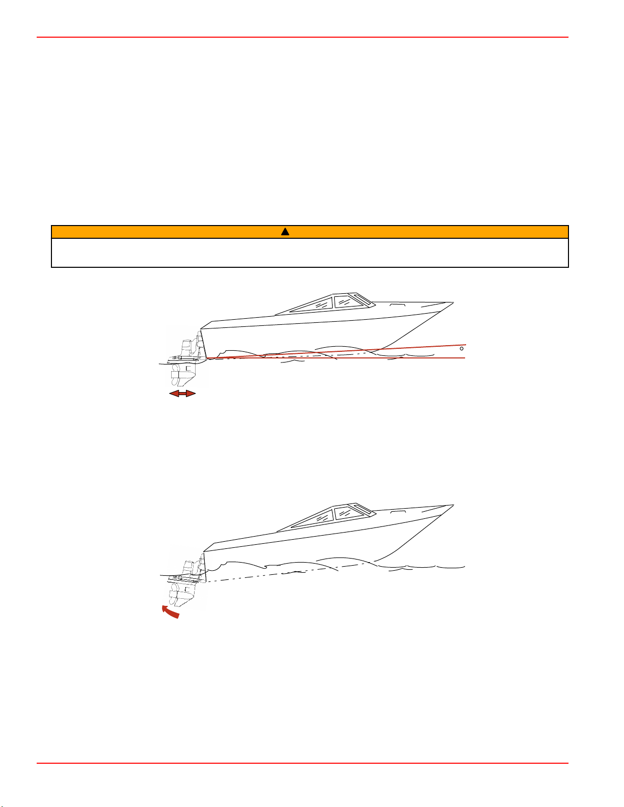
For best performance trim the sterndrive unit so that the boat bottom is at a 3–5° angle to the water.
3 - 5
mc79528
Trimming sterndrive unit up/out can:
• Generally increase top speed
• Increase clearance over submerged objects or a shallow bottom
• Cause boat to accelerate and plane off slower
• In excess, cause boat porpoising (bouncing) or propeller ventilation
• Cause engine overheating if trimmed up/out to a point where any cooling water intake holes are above the waterline
mc78529
Trimming sterndrive unit down/in can:
• Help the boat accelerate and plane off quicker
• Generally improve the ride in choppy water
• In most cases, reduce boat speed
Page 8 90-8M0113856 eng DECEMBER 2015
Page 17
Section 1 - Getting to Know Your Power Package
51185
• If in excess, lower the bow of some boats to a point at which they begin to plow with their bow in the water while on plane.
This can result in an unexpected turn in either direction called bow steering or over steering if any turn is attempted or if a
significant wave is encountered.
mc79530
Single Engine Trim/Trailer
Single engine applications will have a button that can be pressed to trim the sterndrive unit up or down.
To raise the sterndrive unit for trailering, beaching, launching, low speed (below 1200 RPM), and shallow water operation push
the trim button to raise the sterndrive unit to the full up/out position.
Some controls also have a trailer button that trims the sterndrive to a position suitable for trailer purposes only.
Dual Engine Trim/Trailer
NOTICE
If using external tie bars, raising or lowering the drives independently of each other can damage the drive and steering
systems. If using an external tie bar, raise and lower all drives together as a unit.
Dual engine applications may have a single integral button to operate both sterndrive units simultaneously or may have
separate buttons for each sterndrive unit.
Some controls also have a trailer button that trims the sterndrives to a position suitable for trailer purposes only.
Electrical System Overload Protection—3.0 MPI ECT
An electrical overload will either open a fuse or open a circuit breaker. You must find and repair the source of the overload
before replacing the fuse or resetting the circuit breaker.
NOTE: In an emergency, when you must operate the engine but cannot isolate the cause for the high current draw, turn off or
disconnect all accessories connected to the engine and instrumentation wiring. Reset the circuit breaker. If the breaker remains
open, you have not eliminated the electrical overload and the electrical system requires further checks. Contact your authorized
Mercury MerCruiser dealer as soon as possible.
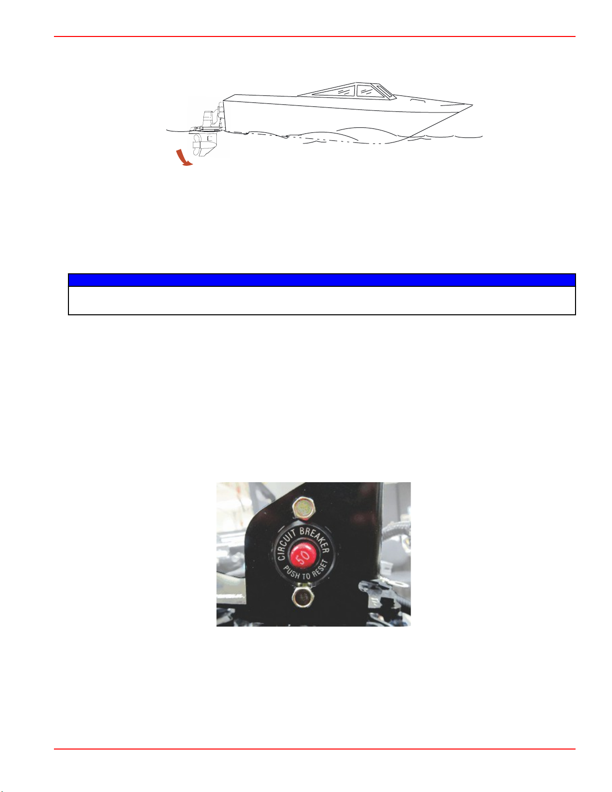
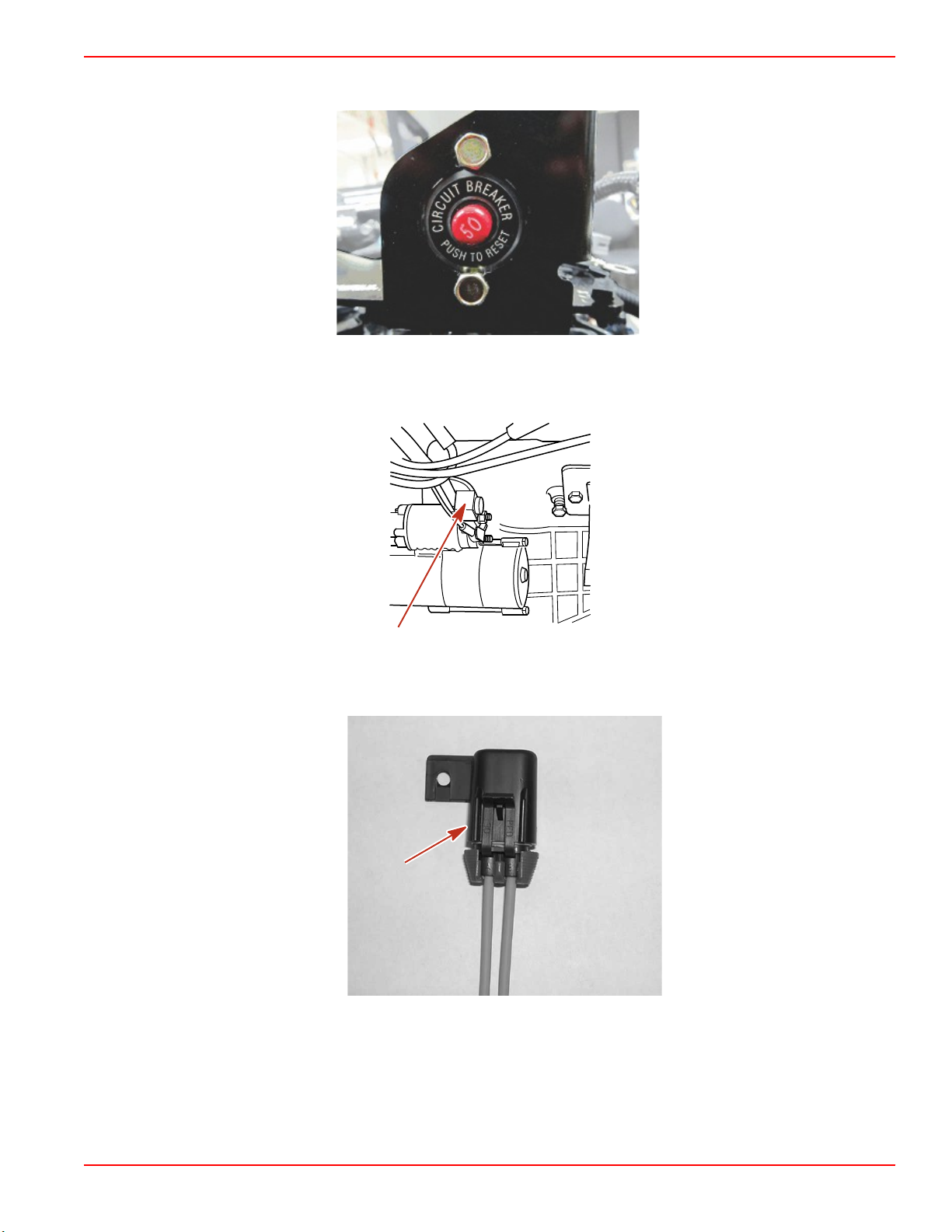
A circuit breaker protects the engine wiring harness and the instrumentation power lead. Reset the breaker by pushing the red
button.
Engine wiring harness and instrumentation circuit breaker
90-8M0113856 eng DECEMBER 2015 Page 9
Page 18
Section 1 - Getting to Know Your Power Package
a
b
32638
a
b
c
d
e
f
g
57136
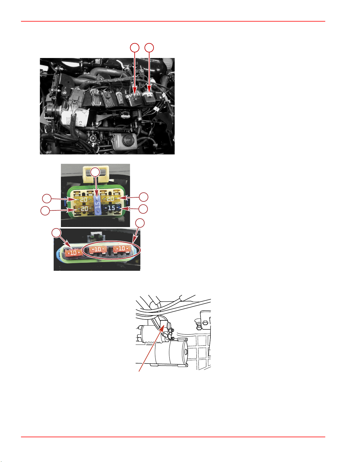
Four fuses protect the main power, fuel pump, ignition, and accessory circuits. Two 10‑amp fuses protect the O2 sensors.
These fuses are located on the top of the engine, underneath the engine information plate.
Fuse locations
a - O2 sensor fuses
b - Main power, fuel pump, ignition, and accessory fuses
a - Fuel pump relay, IAC, ignition coil (20 amp)
b - Fuel injectors, distributor (20 amp)
c - Spare (15 amp)
d - Main power relay, alternator (20 amp)
e - Helm power (15 amp)
f - O2 sensor (10 amp)
g - Spare (10 amp)
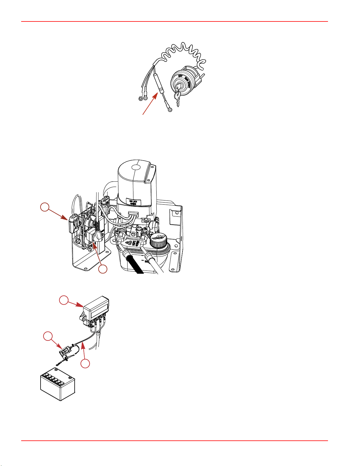
A 90‑amp fuse, located on the large post of the starter solenoid, protects the engine wiring harness if an electrical overload
occurs.
mc74907-1
Engine wiring harness fuse
Page 10 90-8M0113856 eng DECEMBER 2015
Page 19
Section 1 - Getting to Know Your Power Package
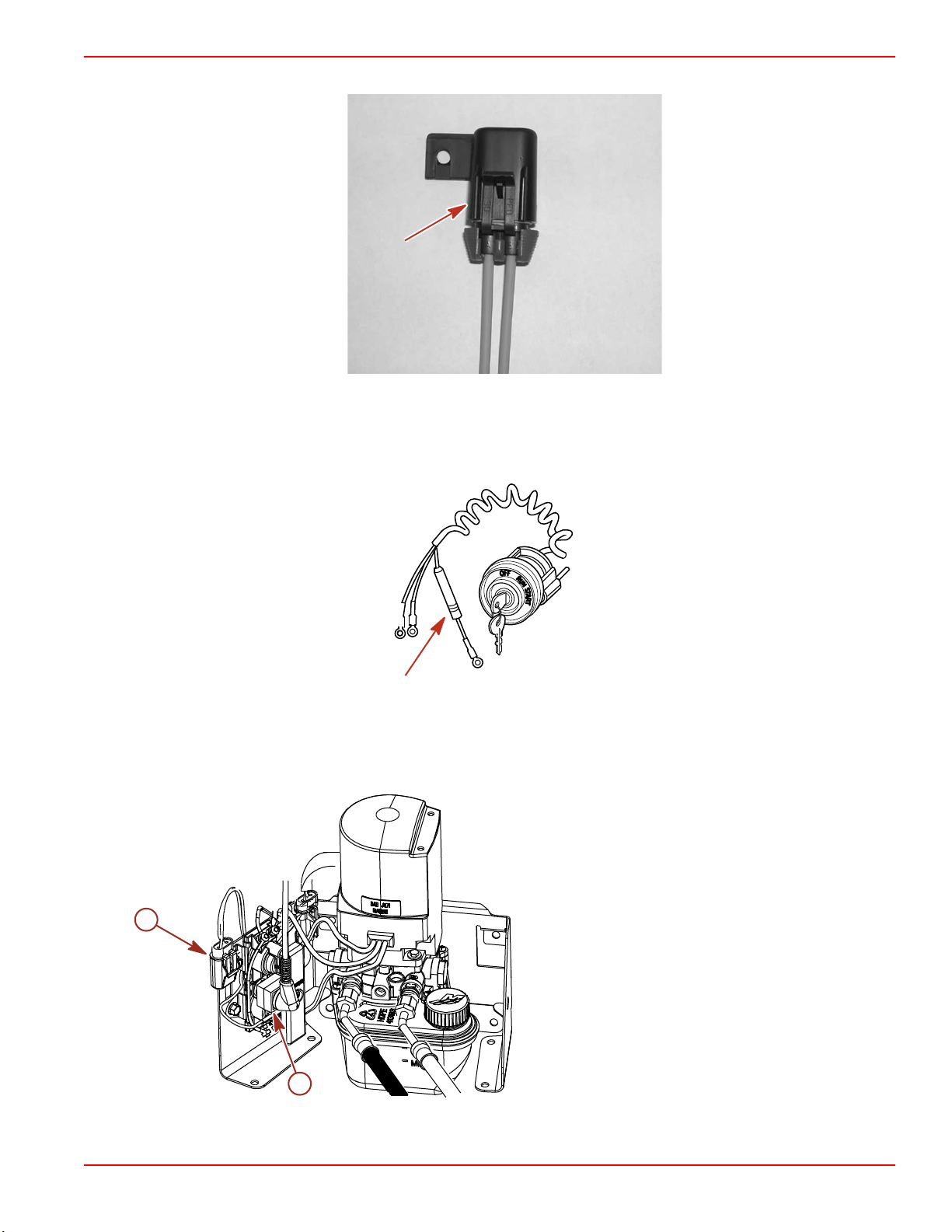
A 15‑amp accessory fuse is located on the rear of the engine. This fuse protects the accessory circuits.
7524
Accessory fuse
In the ignition switch "I" terminal lead, there may be a 20‑amp fuse that protects the electrical system. Check for an open fuse
or open circuit breaker if you turn the ignition key to the start position and nothing happens.
mc70525-1
Ignition switch fuse—typical
The power trim system is protected from overload by a 110‑amp fuse and a 20‑amp spade fuse on the power trim pump. The
trim pump may also have an in‑line circuit protection device in the power trim positive lead near the battery switch or battery
connection.
Power trim fuses
a - 20‑amp spade fuse
b - 110‑amp fuse
a
b
9208
90-8M0113856 eng DECEMBER 2015 Page 11
Page 20
Section 1 - Getting to Know Your Power Package
43608
a
b
c
a
c
50534
b
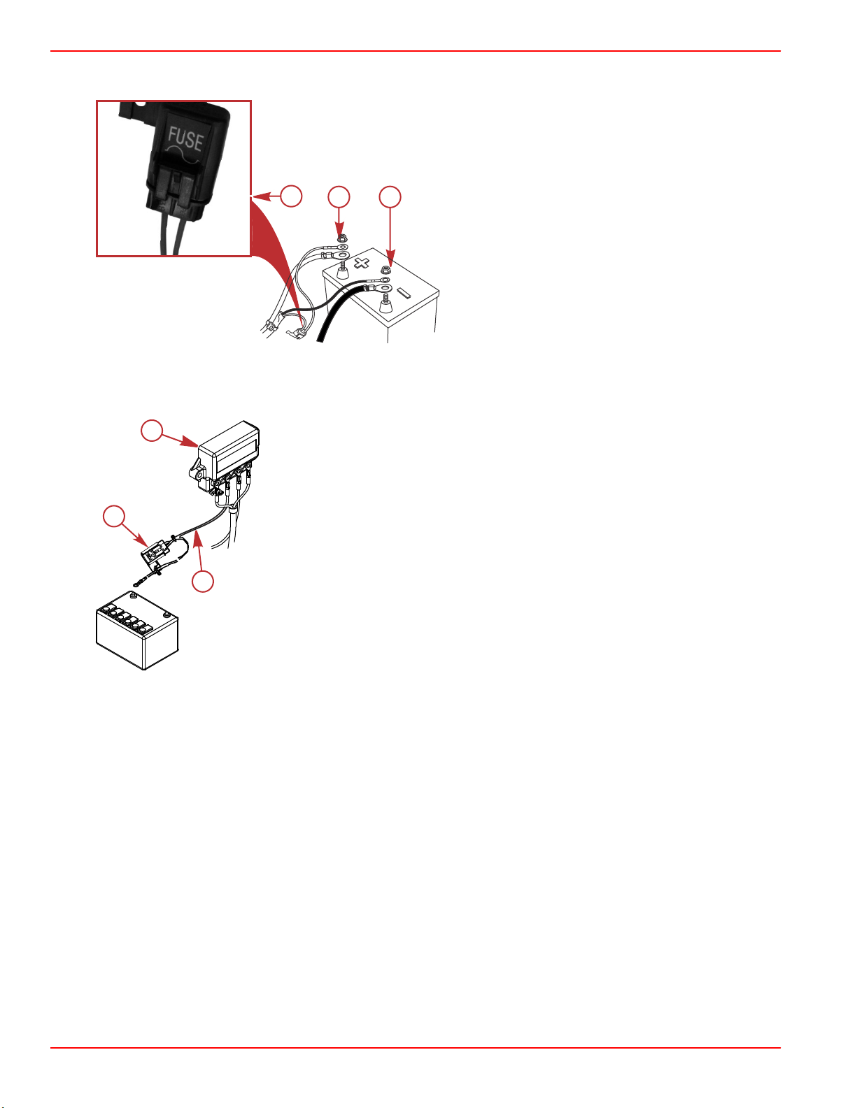
A dedicated power harness supplies continuous power to the PCM, to ensure uninterrupted operation. This harness is
protected by a 5‑amp fuse, located at the engine's battery.
a - 5‑amp fuse
b - Positive battery terminal (harness lead with fuse)
c - Negative battery terminal
The MerCathode system has a 5‑amp fuse, which connects to the positive (+) terminal on the controller. If the fuse is open, the
system will not operate, resulting in a loss of corrosion protection.
a - MerCathode
b - Red/purple wire
c - 5‑amp fuse
Electrical System Overload Protection—3.0 TKS
An electrical overload will either open a fuse or open a circuit breaker. You must find and repair the source of the overload
before replacing the fuse or resetting the circuit breaker.
NOTE: In an emergency, when the engine must be operated and the cause for the high current draw cannot be located and
corrected, turn off or disconnect all accessories connected to the engine and instrumentation wiring. Reset the circuit breaker. If
the breaker remains open, the electrical overload has not been eliminated. Further checks must be made on the electrical
system. Contact your authorized Mercury MerCruiser dealer as soon as possible.
Page 12 90-8M0113856 eng DECEMBER 2015
Page 21
Section 1 - Getting to Know Your Power Package
51185
A circuit breaker protects the engine wiring harness and the instrumentation power lead. Reset the breaker by pushing the red
button.
Engine wiring harness and instrumentation circuit breaker
A 90‑amp fuse, located on the large post of the starter solenoid, protects the engine wiring harness if an electrical overload
occurs.
mc74907-1
Engine wiring harness fuse
A 15‑amp accessory fuse is located on the rear of the engine. This fuse protects the accessory circuits. A 20‑amp fuse is
located on the top of the engine to protect the TKS circuit.
7524
Accessory fuse
90-8M0113856 eng DECEMBER 2015 Page 13
Page 22
Section 1 - Getting to Know Your Power Package
a
c
50534
b
A 20‑amp fuse may be located in the ignition switch "I" terminal lead to protect the electrical system. Check for an open fuse or
open circuit breaker if the ignition key is turned to the start position and nothing happens.
mc70525-1
Ignition switch fuse—typical
The power trim system is protected from overload by a 110‑amp fuse and a 20‑amp spade fuse on the power trim pump. The
trim pump may also have an in‑line circuit protection device in the power trim positive lead near the battery switch or battery
connection.
Power trim fuses
a - 20‑amp spade fuse
b - 110‑amp fuse
a
b
The MerCathode system has a 5‑amp fuse which connects to the positive (+) terminal on the controller. If the fuse is open, the
system will not operate, resulting in a loss of corrosion protection.
a - MerCathode
b - Red/purple wire
c - 5‑amp fuse
9208
Page 14 90-8M0113856 eng DECEMBER 2015
Page 23
Section 1 - Getting to Know Your Power Package
47594
ON ON
OFF
ON
OFF
ON
OFF
ON
OFF
ON
OFF
1
1
1
1
1
1
1
1
1
1
1
OFF
33402
a
b
53403
a
b
ON
6
OFF
Visual and Audio Warning Systems (ECT)
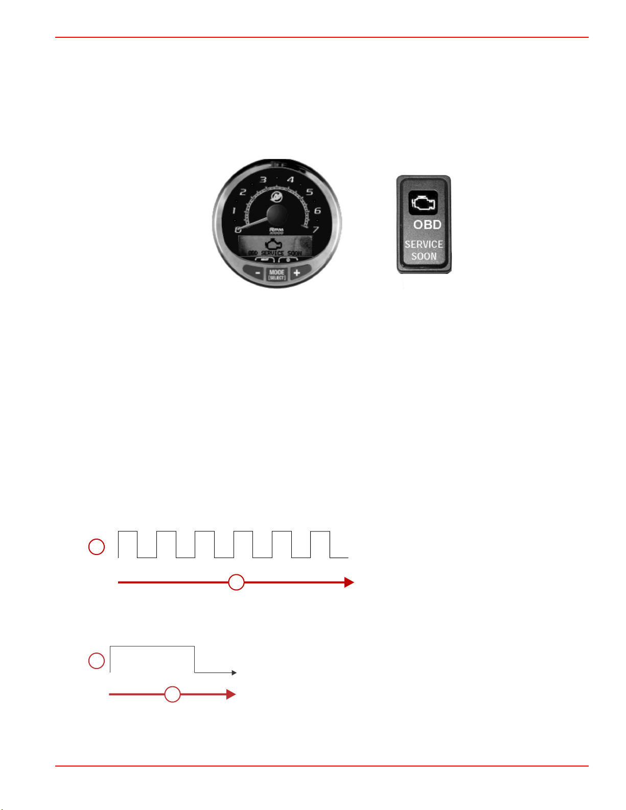
Service Engine Light and OBD‑M MIL Kit
Boats powered by emissions control technology (ECT) catalyzed engines must be equipped with a SmartCraft‑enabled gauge
capable of displaying the service engine icon, or a dash‑mounted service engine light. Malfunction indicator lamp (MIL) kits
containing a dash‑mounted service engine light and a special harness that connects to the engine harness may be purchased
separately.
The service engine icon or MIL will provide a visual indication of a malfunction with the engine's emission control system and
will remain illuminated while the OBD‑M fault is active.
SC 1000 gauge and service engine light
Testing the OBD-M Malfunction Indicator Lamp (MIL)
1. Turn the ignition switch to the on position without cranking the engine.
2. The service engine icon and MIL will remain illuminated for four seconds if the visual indication system is functioning
correctly.
Audio Warning System
IMPORTANT: The audio warning system alerts the operator that a problem has occurred. It does not protect the engine from
damage.
Most faults cause the warning horn circuit to activate. How the warning horn activates depends on the severity of the problem.
There are two warning horn states:
• Caution
• Critical
There is also an alarm that sounds if the helm has not been properly configured using the G3 service tool.
Caution
If a caution state is detected, the audio warning system will sound for six one‑second intervals.
a - Horn (on or off)
b - Time (in seconds)
Critical
If a critical state is detected, the audio warning system sounds for six seconds and then turns off.
Horn (on or off)
a b - Time (in seconds)
Testing the Audio Warning System
1. Turn the key switch to the on position without cranking the engine.
90-8M0113856 eng DECEMBER 2015 Page 15
Page 24

Section 1 - Getting to Know Your Power Package
2. Listen for the audio alarm. The alarm will sound if the system is functioning correctly.
Guardian Strategy
The MerCruiser Engine Guardian system reduces the potential for engine damage by restricting engine power when the PCM
detects a potential problem. Below are some examples of what Engine Guardian monitors:
• Oil pressure
• Engine overspeed
• Exhaust manifold temperature
IMPORTANT: Engine Guardian can reduce power anywhere from 100% to idle, depending on the severity of the problem. If
forced to idle, boat speed might not respond to throttle operation.
The PCM stores the fault for diagnostics. For example, if the water inlet becomes partially blocked, Engine Guardian reduces
the available power level of the engine to help prevent damage from decreased water flow to the engine. If the debris passes
through, and full water flow is restored, Engine Guardian restores engine power to normal.
Audio Warning System—3.0 TKS
Your Mercury MerCruiser power package may be equipped with an Audio Warning System. The audio warning system will not
protect the engine from damage. It is designed to warn the operator that a problem has occurred.
The audio warning system will sound with a continuous horn if one of the following occurs:
• Engine oil pressure too low
• Engine temperature too hot
• Sterndrive oil level too low
NOTICE
A continuous horn indicates a critical fault. Operating the engine during a critical fault can damage components. If the
warning horn emits a continuous beep, do not operate the engine unless avoiding a hazardous situation.
If the alarm sounds, stop the engine immediately. Investigate cause and correct it, if possible. If the cause cannot be
determined, contact your authorized Mercury MerCruiser dealer.
Testing The Audio Warning System
1. Turn the ignition switch to the "ON" position without cranking the engine.
2. Listen for the audio alarm. The alarm will sound if the system is functioning correctly.
Page 16 90-8M0113856 eng DECEMBER 2015
Page 25

Table of Contents
Section 2 - On the Water
Section 2 - On the Water
Safe Boating Recommendations.......................................... 18
Carbon Monoxide Exposure................................................. 19
Be Alert To Carbon Monoxide Poisoning ..................... 19
Stay Clear of Exhaust Areas ........................................ 19
Good Ventilation .......................................................... 19
Poor Ventilation ........................................................... 20
Launching and Boat Operation............................................. 20
Operation Chart ............................................................ 20
Starting and Stopping the Engine—3.0 MPI ECT................. 21
Starting and Stopping the Engine.................................. 21
Starting the Engine ................................................ 21
Stopping the Engine .............................................. 21
Starting the Engine After Stopped While in Gear.......... 21
Starting and Stopping the Engine—3.0 TKS........................ 21
Starting and Stopping the Engine.................................. 21
Starting the Engine ................................................ 21
Stopping the Engine .............................................. 22
Starting the Engine After It Has Been Stopped While In
Gear............................................................................... 22
Throttle Only Operation........................................................ 22
Trailering the Boat................................................................ 22
Freezing Temperature Operation......................................... 22
Drain Plug and Bilge Pump.................................................. 22
Protecting People in the Water............................................. 23
While You Are Cruising ................................................ 23
While Boat Is Stationary ............................................... 23
High‑Speed and High‑Performance Operation..................... 23
Passenger Safety in Pontoon Boats and Deck Boats.......... 23
Boats Having an Open Front Deck ............................... 23
Boats With Front‑Mounted, Raised Pedestal Fishing
Seats ............................................................................ 23
Wave and Wake Jumping..................................................... 24
Impact with Underwater Hazards......................................... 24
Drive Unit Impact Protection ......................................... 25
Conditions Affecting Operation............................................. 25
Weight Distribution (Passengers and Gear) Inside the
Boat............................................................................... 25
The Bottom of the Boat.................................................. 25
Cavitation....................................................................... 25
Ventilation...................................................................... 25
Elevation and Climate.................................................... 26
Propeller Selection.........................................................26
Getting Started—3.0 MPI ECT............................................. 26
20‑Hour Break‑In Period................................................ 26
After Break‑In Period..................................................... 26
End of First Season Checkup........................................ 27
Getting Started—3.0 TKS..................................................... 27
20‑Hour Break‑In Period................................................ 27
After Break‑In Period..................................................... 27
End of First Season Checkup........................................ 27
2
90-8M0113856 eng DECEMBER 2015 Page 17
Page 26

Section 2 - On the Water
Safe Boating Recommendations
To safely enjoy the waterways, familiarize yourself with local and all other governmental boating regulations and restrictions
and consider the following suggestions.
Know and obey all nautical rules and laws of the waterways.
• We recommend that all powerboat operators complete a boating safety course. In the U.S., the U.S. Coast Guard Auxiliary,
the Power Squadron, the Red Cross, and your state or provincial boating law enforcement agency provide courses. For
more information in the U.S., call the Boat U.S. Foundation at 1‑800‑336‑BOAT (2628).
Perform safety checks and required maintenance.
• Follow a regular schedule and ensure that all repairs are properly made.
Check safety equipment onboard.
• Here are some suggestions of the types of safety equipment to carry when boating:
Approved fire extinguishers
Signal devices: flashlight, rockets or flares, flag, and whistle or horn
Tools necessary for minor repairs
Anchor and extra anchor line
Manual bilge pump and extra drain plugs
Drinking water
Radio
Paddle or oar
Spare propeller, thrust hubs, and an appropriate wrench
First aid kit and instructions
Waterproof storage containers
Spare operating equipment, batteries, bulbs, and fuses
Compass and map or chart of the area
Personal flotation device (one per person onboard)
Watch for signs of weather change and avoid foul weather and rough‑sea boating.
Tell someone where you are going and when you expect to return.
Passenger boarding.
• Stop the engine whenever passengers are boarding, unloading, or are near the back (stern) of the boat. Shifting the drive
unit into neutral is not sufficient.
Use personal flotation devices.
• Federal law requires that there be a U.S. Coast Guard‑approved life jacket (personal flotation device), correctly sized and
readily accessible for every person onboard, plus a throwable cushion or ring. We strongly advise that everyone wear a life
jacket at all times while in the boat.
Prepare other boat operators.
• Instruct at least one person onboard in the basics of starting and operating the engine and boat handling in case the driver
becomes disabled or falls overboard.
Do not overload your boat.
• Most boats are rated and certified for maximum load (weight) capacities (refer to your boat's capacity plate). Know your
boat's operating and loading limitations. Know if your boat will float if it is full of water. When in doubt, contact your
authorized Mercury Marine dealer or the boat manufacturer.
Ensure that everyone in the boat is properly seated.
• Do not allow anyone to sit or ride on any part of the boat that was not intended for such use. This includes the backs of
seats, gunwales, transom, bow, decks, raised fishing seats, and any rotating fishing seat. Passengers should not sit or ride
anywhere that sudden unexpected acceleration, sudden stopping, unexpected loss of boat control, or sudden boat
movement could cause a person to be thrown overboard or into the boat. Ensure that all passengers have a proper seat
and are in it before any boat movement.
Never operate a boat while under the influence of alcohol or drugs. It is the law.
• Alcohol or drugs can impair your judgment and greatly reduce your ability to react quickly.
Know your boating area and avoid hazardous locations.
Page 18 90-8M0113856 eng DECEMBER 2015
Page 27
Section 2 - On the Water
43367
Be alert.
• The operator of the boat is responsible by law to maintain a proper lookout by sight and hearing. The operator must have
an unobstructed view particularly to the front. No passengers, load, or fishing seats should block the operator's view when
the boat is above idle or planing transition speed. Watch out for others, the water, and your wake.
Never drive your boat directly behind a water skier.
• Your boat traveling at 40 km/h (25 mph) will overtake a fallen skier who is 61 m (200 ft) in front of you in five seconds.
Watch fallen skiers.
• When using your boat for waterskiing or similar activities, always keep a fallen or down skier on the operator's side of the
boat while returning to attend to the skier. The operator should always have the down skier in sight and never back up to
the skier or anyone in the water.
Report accidents.
• Boat operators are required by law to file a boating accident report with their state boating law enforcement agency when
their boat is involved in certain boating accidents. A boating accident must be reported if 1) there is loss of life or probable
loss of life, 2) there is personal injury requiring medical treatment beyond first aid, 3) there is damage to boats or other
property where the damage value exceeds $500.00, or 4) there is complete loss of the boat. Seek further assistance from
local law enforcement.
Carbon Monoxide Exposure
Be Alert To Carbon Monoxide Poisoning
Carbon monoxide (CO) is a deadly gas that is present in the exhaust fumes of all internal combustion engines, including the
engines that propel boats, and the generators that power boat accessories. By itself, CO is odorless, colorless, and tasteless,
but if you can smell or taste engine exhaust, you are inhaling CO.
Early symptoms of carbon monoxide poisoning, which are similar to the symptoms of seasickness and intoxication, include
headache, dizziness, drowsiness, and nausea.
WARNING
!
Inhaling engine exhaust gases can result in carbon monoxide poisoning, which can lead to unconsciousness, brain damage,
or death. Avoid exposure to carbon monoxide.
Stay clear from exhaust areas when engine is running. Keep the boat well‑ventilated while at rest or underway.
Stay Clear of Exhaust Areas
Engine exhaust gases contain harmful carbon monoxide. Avoid areas of concentrated engine exhaust gases. When engines
are running, keep swimmers away from the boat, and do not sit, lie, or stand on swim platforms or boarding ladders. While
underway, do not allow passengers to be positioned immediately behind the boat (platform dragging, teak/body surfing). This
dangerous practice not only places a person in an area of high engine exhaust concentration, but also subjects them to the
possibility of injury from the boat propeller.
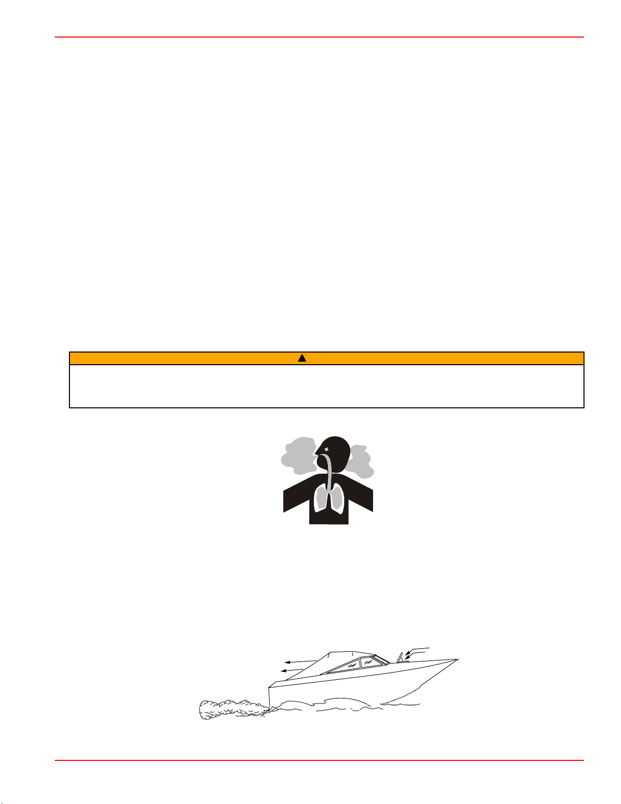
Good Ventilation
Ventilate the passenger area, open side curtains or forward hatches to remove fumes.
Example of desired air flow through the boat:
90-8M0113856 eng DECEMBER 2015 Page 19
Page 28
Section 2 - On the Water
21626
a
b
a
b
43368
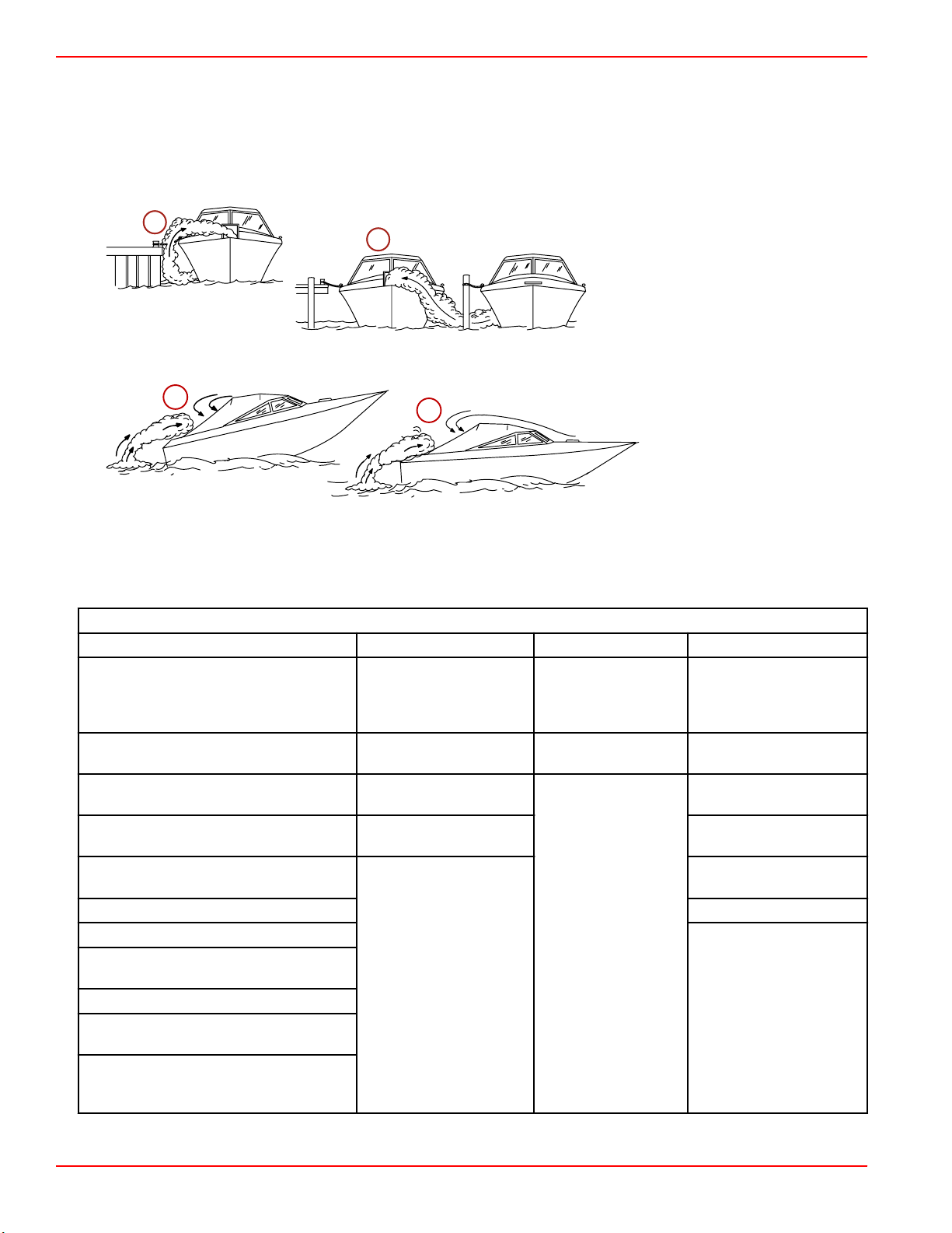
Poor Ventilation
Under certain running or wind conditions, permanently enclosed or canvas enclosed cabins or cockpits with insufficient
ventilation may draw in carbon monoxide. Install one or more carbon monoxide detectors in your boat.
Although the occurrence is rare, on a very calm day, swimmers and passengers in an open area of a stationary boat that
contains or is near a running engine may be exposed to a hazardous level of carbon monoxide.
1. Examples of poor ventilation while the boat is stationary:
a - Operating the engine when the boat
is moored in a confined space
b - Mooring close to another boat that
has its engine operating
2. Examples of poor ventilation while the boat is moving:
a - Operating the boat with the
trim angle of the bow too
high
b - Operating the boat with no
forward hatches open
(station wagon effect)
Launching and Boat Operation
IMPORTANT: Install bilge drain plug prior to launching boat.
Operation Chart
Operation Chart
BEFORE STARTING AFTER STARTING WHILE UNDERWAY AFTER STOPPING
Observe all gauges to
Install bilge drain plug.
Open engine hatch.
Turn battery switch on.
Operate bilge blowers. Check steering operation.
Open fuel shut off valve.
Open seacock, if equipped. Drain bilge.
Close the drain system.
Place sterndrive unit in full down/in
position.
Check the engine oil.
Perform all other checks specified by your
dealer and/or boatbuilder.
Listen for the audio warning alarm to
sound when the ignition switch is in the
"ON" position.
check condition of engine.
If not normal, stop engine.
Check for fuel, oil, water,
fluid, and exhaust leaks.
Check shift and throttle
control operation.
Observe all gauges to
check condition of
engine. If not normal,
stop engine.
Listen for the audio
alarm.
Turn ignition key to the
"OFF" position.
Turn battery switch to the
"OFF" position.
Close fuel shut off valve.
Close seacock, if
equipped.
Flush cooling system if in
saltwater.
Page 20 90-8M0113856 eng DECEMBER 2015
Page 29
Section 2 - On the Water
Starting and Stopping the Engine—3.0 MPI ECT
Starting and Stopping the Engine
NOTE: Only perform those functions applicable to your power package.
Starting the Engine
1.
Check all items listed in the Operation Chart.
2. Place the remote control handle in neutral.
NOTICE
Without sufficient cooling water, the engine, the water pump, and other components will overheat and suffer damage. Provide
a sufficient supply of water to the water inlets during operation.
WARNING
!
Explosive fumes contained in the engine compartment can cause serious injury or death from fire or explosion. Before
starting the engine, operate the bilge blower or vent the engine compartment for at least five minutes.
3. Turn ignition key to "START." Release key when engine starts and allow switch to return to "ON" position. Allow engine to
warm up (6–10 minutes on first start of the day).
4. If engine does not start after three attempts:
a.
Push the throttle only button and position the remote control handle/throttle lever to the 1/4 throttle position.
b. Turn ignition key to "START." Release key when engine starts and allow switch to return to "ON" position.
5. If engine does not start after step 4:
a. Move the remote control handle/throttle lever to full throttle position, then return to 1/4 throttle.
b. Turn ignition key to "START." Release key when engine starts and allow switch to return to "ON" position.
6. Inspect the power package for fuel, oil, water, and exhaust leaks.
7. Move control handle with a firm, quick motion forward to shift to forward gear, or backward to shift to reverse. After shifting,
advance throttle to desired setting.
NOTICE
Shifting into gear at engine speeds above idle will damage the drive system. Shift the drive into gear only when the engine is
operating at idle.
Stopping the Engine
1. Move the remote control handle to neutral/idle and allow the engine to slow to idle speed. If engine has been operated at
high speed for a long period of time, allow the engine to cool at idle speed for 3–5 minutes.
2. Turn ignition key to the "OFF" position.
Starting the Engine After Stopped While in Gear
IMPORTANT: Avoid stopping the engine if the sterndrive is in gear.
If you stopped the engine while in gear, return the shift control to neutral and resume normal starting procedures.
Starting and Stopping the Engine—3.0 TKS
Starting and Stopping the Engine
NOTE: Only perform those functions applicable to your power package.
Starting the Engine
1.
Check all items listed in the Operation Chart.
2. Place the remote control handle in neutral.
NOTICE
Without sufficient cooling water, the engine, the water pump, and other components will overheat and suffer damage. Provide
a sufficient supply of water to the water inlets during operation.
WARNING
!
Explosive fumes contained in the engine compartment can cause serious injury or death from fire or explosion. Before
starting the engine, operate the bilge blower or vent the engine compartment for at least five minutes.
90-8M0113856 eng DECEMBER 2015 Page 21
Page 30

Section 2 - On the Water
3. Turn ignition key to "START." Release key when engine starts and allow switch to return to "ON" position. Allow the engine
to warm up 6–10 minutes on the first start of the day.
NOTE: If the engine has not run for a long period it may require a couple of attempts.
4. If engine does not start after three attempts:
a.
Push the throttle only button and position the remote control handle/throttle lever to the 1/4 throttle position.
b. Turn ignition key to "START." Release key when engine starts and allow switch to return to "ON" position.
5. If engine does not start after step 4:
a. Move the remote control handle/throttle lever to full throttle position, then return to 1/4 throttle.
b. Turn ignition key to "START." Release key when engine starts and allow switch to return to "ON" position.
6. Inspect the power package for fuel, oil, water, and exhaust leaks.
7. Move control handle with a firm, quick motion forward to shift to forward gear, or backward to shift to reverse. After shifting,
advance throttle to the desired setting.
NOTICE
Shifting into gear at engine speeds above idle will damage the gearcase. Shifting into gear when the engine is not running
can misalign the clutch, preventing proper shifting. Always shift the gearcase into gear when the engine is operating at idle. If
you must shift while the engine is not operating, rotate the propeller shaft in the appropriate direction during shifting.
Stopping the Engine
1. Move the remote control handle to neutral/idle and allow the engine to slow to idle speed. If engine has been operated at
high speed for a long period of time, allow the engine to cool at idle speed for 3 to 5 minutes.
2. Turn ignition key to the "OFF" position.
Starting the Engine After It Has Been Stopped While In Gear
IMPORTANT: Avoid stopping the engine if the sterndrive unit is in gear. If the engine does stop, refer to the following
procedure:
1. Push and pull repeatedly on the remote control handle until handle returns to the neutral/idle position. This may take
several tries if the power package was operating above idle RPM when the engine stopped.
2. After the handle returns to the neutral/idle position, resume normal starting procedures.
Throttle Only Operation
1.
Refer to Remote Controls section for remote control features.
2. Move the control lever to the idle/neutral position.
3. Depress and hold the throttle only button, and move the control lever to the idle/forward or idle/reverse position.
4. Advancing the control lever beyond the idle/forward or idle/reverse position will cause engine speed to increase.
IMPORTANT: Moving the control lever back to the idle/neutral position will disengage the throttle only button and allow the
engine to shift into gear.
5. Throttle only mode is deactivated by moving the control lever to the idle/neutral position. Moving the control lever from the
idle/neutral position to the idle/forward or idle/reverse position without pressing the throttle only button will shift the unit into
the chosen gear.
Trailering the Boat
Your boat can be trailered with the sterndrive unit in the up or down position. Adequate clearance is required between the road
and sterndrive when transporting.
If adequate road clearance is a problem, place the sterndrive unit in full trailer position and support it with an optional trailer kit
which is available from your authorized Mercury MerCruiser dealer.
Freezing Temperature Operation
IMPORTANT: If the boat is operated during periods of freezing temperature, precautions must be taken to prevent freeze
damage to the power package. Damage caused by freezing is not covered by Mercury MerCruiser Limited Warranty.
Drain Plug and Bilge Pump
The engine compartment in your boat is a natural place for water to collect. For this reason, boats are normally equipped with a
drain plug and/or a bilge pump. It is very important to check these items on a regular basis to ensure that the water level does
not come into contact with your power package. Components on your engine will be damaged if submerged. Damage caused
by submersion is not covered by the Mercury MerCruiser Limited Warranty.
Page 22 90-8M0113856 eng DECEMBER 2015
Page 31

Section 2 - On the Water
21604
Protecting People in the Water
While You Are Cruising
It is very difficult for a person in the water to take quick action to avoid a boat heading in their direction, even at slow speeds.
Always slow down and exercise extreme caution any time you are boating in an area where there might be people in the water.
Whenever a boat is moving (even coasting) and the gear shift is in neutral, there is sufficient force by the water on the propeller
to cause the propeller to rotate. This neutral propeller rotation can cause serious injury.
While Boat Is Stationary
WARNING
!
A spinning propeller, a moving boat, or any solid device attached to the boat can cause serious injury or death to swimmers.
Stop the engine immediately whenever anyone in the water is near your boat.
Shift into neutral and shut off the engine before allowing people to swim or be in the water near your boat.
High‑Speed and High‑Performance Operation
If your boat is considered a high‑speed or high‑performance boat and you are unfamiliar with its operation, we recommend that
you never operate it at its high speed capability without first requesting an initial orientation and demonstration ride with your
dealer or an operator experienced with your boat. For additional information, refer to Hi‑Performance Boat Operation booklet
(90‑849250R03) from your dealer, distributor, or Mercury Marine.
Passenger Safety in Pontoon Boats and Deck Boats
Whenever the boat is in motion, observe the location of all passengers. Do not allow any passengers to stand or use seats
other than those designated for traveling faster than idle speed. A sudden reduction in boat speed, such as plunging into a
large wave or wake, a sudden throttle reduction, or a sharp change of boat direction, could throw them over the front of the
boat. Falling over the front of the boat between the two pontoons will position them to be run over.
Boats Having an Open Front Deck
No one should ever be on the deck in front of the fence while the boat is in motion. Keep all passengers behind the front fence
or enclosure.
Persons on the front deck could easily be thrown overboard or persons dangling their feet over the front edge could get their
legs caught by a wave and pulled into the water.
mc79555-1
WARNING
!
Sitting or standing in an area of the boat not designed for passengers at speeds above idle can cause serious injury or death.
Stay back from the front end of deck boats or raised platforms and remain seated while the boat is in motion.
Boats With Front‑Mounted, Raised Pedestal Fishing Seats
Elevated fishing seats are not intended for use when the boat is traveling faster than idle or trolling speed. Sit only in seats
designated for traveling at faster speeds.
90-8M0113856 eng DECEMBER 2015 Page 23
Page 32

Section 2 - On the Water
Any unexpected, sudden reduction in boat speed could result in the elevated passenger falling over the front of the boat.
mc79557-1
Wave and Wake Jumping
WARNING
!
Wave or wake jumping can cause serious injury or death from occupants being thrown within or out of the boat. Avoid wave
or wake jumping whenever possible.
mc79680-1
Operating recreational boats over waves and wakes is a natural part of boating. However, when this activity is done with
enough speed to force the boat hull partially or completely out of the water, certain hazards arise, particularly when the boat
reenters the water.
The primary concern is the boat changing direction while in the midst of the jump. In such cases the landing may cause the
boat to violently veer in a new direction. Such a sharp change in direction or turn can cause occupants to be thrown out of their
seats or out of the boat.
There is another less common hazardous result from allowing your boat to launch off of a wave or wake. If the bow of your boat
pitches down far enough while airborne, upon water contact it may penetrate under the water surface and submarine for an
instant. This will bring the boat nearly to a stop in an instant and can send the occupants flying forward. The boat may also veer
sharply to one side.
Impact with Underwater Hazards
Reduce speed and proceed with caution whenever you're driving a boat in shallow water or in areas where the waters are
suspected of having underwater obstacles that could be struck by the underwater drive components, rudder, or the boat
bottom.
mc79679-1
IMPORTANT: The most important thing you can do to help reduce injury or impact damage from striking a floating or
underwater object is control the boat speed. Under these conditions, boat speed should be kept to a maximum speed of
24–40 km/h (15–25 mph).
Striking a floating/underwater object may result in an infinite number of situations. Some of these situations could result in the
following:
• The boat could move suddenly in a new direction. Such a sharp change in direction or turn can cause occupants to be
thrown out of their seats or out of the boat.
• A rapid reduction in speed. This will cause occupants to be thrown forward, even out of the boat.
• Impact damage to the underwater drive components, rudder, and/or boat.
Page 24 90-8M0113856 eng DECEMBER 2015
Page 33

Section 2 - On the Water
Keep in mind, one of the most important things you can do to help reduce injury or impact damage in these situations is control
the boat speed. Boat speed should be kept to a minimum planing speed when driving in waters known to have underwater
obstacles.
After striking a submerged object, stop the engine as soon as possible and inspect the drive system for any broken or loose
parts. If damage is present or suspected, the power package should be taken to an authorized Mercury MerCruiser dealer for a
thorough inspection and necessary repair.
The boat should be checked for hull fractures, transom fractures, and water leaks.
Operating with damaged underwater drive components, rudder, or boat bottom could cause additional damage to other parts of
the power package, or could affect control of the boat. If continued operation is necessary, do so at greatly reduced speeds.
WARNING
!
Operating a boat or engine with impact damage can result in product damage, serious injury, or death. If the vessel
experiences any form of impact, have an authorized Mercury Marine dealer inspect and repair the vessel or power package.
Drive Unit Impact Protection
The power trim hydraulic system is designed to provide impact protection for the sterndrive unit. If a submerged object is struck
while the boat is moving forward, the hydraulic system will cushion the kickup of the sterndrive unit as it clears the object,
reducing damage to the unit. After the sterndrive unit has cleared the object, the hydraulic system allows the sterndrive unit to
return to its original operating position, preventing loss of steering control and engine overspeed.
Use extreme caution when operating in shallow water or where underwater objects are known to be present. No impact
protection is provided in reverse; use extreme care to prevent striking submerged objects while operating in reverse.
IMPORTANT: Impact protection system cannot be designed to ensure total protection from impact damage under all
conditions.
Conditions Affecting Operation
Weight Distribution (Passengers and Gear) Inside the Boat
Shifting weight to rear (stern):
• Generally increases speed and engine RPM
• Causes bow to bounce in choppy water
• Increases danger of following wave splashing into the boat when coming off plane
• At extremes, can cause the boat to porpoise
Shifting weight to front (bow):
• Improves ease of planing
• Improves rough water ride
• At extremes, can cause the boat to veer back and forth (bow steer)
The Bottom of the Boat
To maintain maximum speed, the boat bottom should be:
• Clean, free of barnacles and marine growth
• Free of distortion; nearly flat where it contacts the water
• Straight and smooth, fore and aft
Marine vegetation may accumulate when the boat is docked. This growth must be removed before operation; it may clog the
water inlets and cause the engine to overheat.
Cavitation
Cavitation occurs when water flow cannot follow the contour of a fast‑moving underwater object, such as a gear housing or a
propeller. Cavitation increases propeller speed while reducing boat speed. Cavitation can seriously erode the surface of the
gear housing or the propeller. Common causes of cavitation are:
• Weeds or other debris snagged on the propeller
• Bent propeller blade
• Raised burrs or sharp edges on the propeller
Ventilation
Ventilation is caused by surface air or exhaust gases that are introduced around the propeller resulting in propeller speed‑up
and a reduction in boat speed. Air bubbles strike the propeller blade and cause erosion of the blade surface. If allowed to
continue, eventual blade failure (breakage) will occur. Excessive ventilation is usually caused by:
90-8M0113856 eng DECEMBER 2015 Page 25
Page 34

Section 2 - On the Water
• Drive unit trimmed out too far
• A missing propeller diffuser ring
• A damaged propeller or gear housing, which allows exhaust gases to escape between propeller and gear housing
• Drive unit installed too high on transom
Elevation and Climate
Elevation and climate changes will affect the performance of your power package. Loss of performance can be caused by:
• Higher elevations
• Higher temperatures
• Low barometric pressures
• High humidity
For you to have optimum engine performance under changing weather conditions, it is essential that the engine be propped to
allow the engine to operate at or near the top end of the specified maximum RPM range with a normal boat load during your
normal boating weather conditions.
In most cases, recommended RPM can be achieved by changing to a lower pitch propeller.
Propeller Selection
IMPORTANT: The engines covered in this manual are equipped with an RPM rev‑limiter that is set to an upper RPM limit. This
limit, which is slightly above the normal operating range of the engine, helps prevent damage from excessive engine RPM.
Once the RPM returns to the recommended operating RPM range, normal engine operation resumes.
The boat manufacturer and the selling dealer are responsible for equipping the power package with the correct propeller. Refer
to Mercury Marine's web page https://www.mercurymarine.com/en/us/propellers/selector/#/step‑one
Select a propeller that will allow the engine power package to operate at or near the top end of the recommended WOT
operating RPM range with a normal load.
If full‑throttle operation is below the recommended range, the propeller must be changed to prevent loss of performance and
possible engine damage. On the other hand, operating an engine above the recommended operating RPM range will cause
higher than normal wear and damage.
After initial propeller selection, the following common problems may require that the propeller be changed to a lower pitch.
• Warmer weather and greater humidity cause a loss of RPM.
• Operating in a higher elevation causes a loss of RPM.
• Operating with a dirty boat bottom causes a loss of RPM.
• Operating with increased load (additional passengers, pulling skiers) causes a loss of RPM.
For better acceleration, such as is needed for waterskiing, use the next lower pitch propeller. When not pulling skiers, do not
operate at full throttle when using the lower pitch propeller.
.
Getting Started—3.0 MPI ECT
20‑Hour Break‑In Period
IMPORTANT: The first 20 hours of operation is the engine break‑in period. Correct break‑in is essential to obtain minimum oil
consumption and maximum engine performance. During this break‑in period, the following rules must be observed:
• Do not operate below 1500 RPM for extended periods of time for the first 10 hours. Shift into gear as soon as possible after
starting and advance the throttle above 1500 RPM if conditions permit safe operation.
• Do not operate at one speed consistently for extended periods.
• Do not exceed 3/4 throttle during the first 10 hours. During the next 10 hours, occasional operation at full throttle is
permissible (five minutes at a time maximum).
• Avoid full throttle acceleration from idle speed.
• Do not operate at full throttle until the engine reaches normal operating temperature.
• Frequently check engine oil level. Add oil as needed. It is normal for oil consumption to be high during the break‑in period.
After Break‑In Period
To help extend the life of your Mercury MerCruiser power package, the following recommendations should be considered;
• Ensure that propeller allows the engine to operate at or near the top of the specified WOT RPM range (Refer to
Specifications and Maintenance) when at full throttle with a normal boat load.
• Operation at 3/4 throttle setting or lower is recommended. Refrain from prolonged operation at WOT RPM.
•
Change the engine oil and oil filter. Refer to Maintenance.
Page 26 90-8M0113856 eng DECEMBER 2015
Page 35

Section 2 - On the Water
End of First Season Checkup
At the end of the first season of operation, contact an authorized Mercury MerCruiser dealer to discuss and/or perform
scheduled maintenance items. If you are in an area where the product is operated continuously, year‑round, you should contact
your dealer at the end of the first 100 hours of operation or once yearly, whichever occurs first.
Getting Started—3.0 TKS
20‑Hour Break‑In Period
IMPORTANT: The first 20 hours of operation is the engine break‑in period. Correct break‑in is essential to obtain minimum oil
consumption and maximum engine performance. During this break‑in period, the following rules must be observed:
• Do not operate below 1500 RPM for extended periods of time for the first 10 hours. Shift into gear as soon as possible after
starting and advance the throttle above 1500 RPM if conditions permit safe operation.
• Do not operate at one speed consistently for extended periods.
• Do not exceed 3/4 throttle during the first 10 hours. During the next 10 hours, occasional operation at full throttle is
permissible (five minutes at a time maximum).
• Avoid full throttle acceleration from idle speed.
• Do not operate at full throttle until the engine reaches normal operating temperature.
• Frequently check engine oil level. Add oil as needed. It is normal for oil consumption to be high during the break‑in period.
After Break‑In Period
To help extend the life of your Mercury MerCruiser power package, follow these recommendations:
• Ensure that the propeller allows the engine to operate at or near the top of the specified WOT RPM range. Refer to
Specifications and Maintenance.
• Operate the engine at 3/4 throttle or lower. Refrain from prolonged operation at wide‑open throttle RPM.
•
Change the engine oil and oil filter. Refer to Maintenance.
NOTE: If the boat is equipped with a gauge that displays scheduled oil changes, do not reset the gauge after this oil
change.
•
Change the transmission oil and filter. Refer to Maintenance (ZF transmission models).
1.
End of First Season Checkup
At the end of the first season of operation, contact an authorized Mercury MerCruiser dealer to discuss and/or perform
scheduled maintenance items. If you are in an area where the product is operated continuously, year‑round, you should contact
your dealer at the end of the first 100 hours of operation or once yearly, whichever occurs first.
1. Require fluid and filter change after the first 25 hours and then every 100 hours.
90-8M0113856 eng DECEMBER 2015 Page 27
Page 36

Section 2 - On the Water
Notes:
Page 28 90-8M0113856 eng DECEMBER 2015
Page 37

Table of Contents
Section 3 - Specifications
Section 3 - Specifications
Specifications—3.0 MPI ECT............................................... 30
Engine Specifications—3.0 MPI ECT............................ 30
Fuel Requirements........................................................ 30
Fuel Ratings .......................................................... 30
Using Reformulated (Oxygenated) Gasoline (USA
Only) ...................................................................... 30
Gasoline Containing Alcohol ................................. 31
Bu16 Butanol Fuel Blends .............................. 31
Methanol and Ethanol Fuel Blends ................ 31
Engine Oil...................................................................... 31
Fluid Specifications........................................................ 32
Sterndrives ............................................................ 32
Engine ................................................................... 32
Specifications—3.0 TKS....................................................... 32
Engine Specifications—3.0 TKS.................................... 32
Fuel Requirements........................................................ 33
Fuel Ratings .......................................................... 33
Using Reformulated (Oxygenated) Gasolines (USA
Only) ...................................................................... 33
Gasolines Containing Alcohol ............................... 33
Engine Oil...................................................................... 34
Fluid Specifications........................................................ 34
Sterndrives ............................................................ 34
Engine ................................................................... 34
3
90-8M0113856 eng DECEMBER 2015 Page 29
Page 38

Section 3 - Specifications
Specifications—3.0 MPI ECT
Engine Specifications—3.0 MPI ECT
NOTE: Performance specifications are obtained and corrected in accordance with SAE J1228/ISO 8665 Crankshaft Power.
All measurements are taken with the engine at normal operating temperature.
RPM range is measured using an accurate service tachometer with the engine at normal operating temperatures.
Oil pressure must be checked with the engine at normal operating temperature.
NOTE: Oil pressure specifications are for reference and may vary.
Propshaft power
Displacement
Alternator amperage
RPM
Minimum oil pressure
Thermostat
Timing at idle
Firing order
Minimum battery rating
Spark plug type
Spark plug gap
Emission control system
101 kW (135 hp)
3.0 L (181 cid)
Hot 72 A
Cold 65 A
WOT 4400–4800
Rev limiter 4950
Idle in neutral 700
At 2000 RPM 207 kPa (30 psi)
At idle 28 kPa (4 psi)
Seawater‑cooled models
Models with Closed Cooling
375 CCA, 475 MCA, 90 Ah
Electronic control (EC), heated oxygen sensor
71° C (160° F)
Not Adjustable
1‑3‑4‑2
AC MR43LTS
Champion RS12YC
NGK BPR6EFS
0.9 mm (0.045 in.)
(HO2S), catalyst
Fuel Requirements
NOTICE
Running out of fuel can damage catalyst components. Do not allow the fuel tanks to become empty during operation.
IMPORTANT: Use of improper gasoline can damage your engine. Engine damage resulting from the use of improper
gasoline is considered misuse of the engine and will not be covered under the limited warranty.
Fuel Ratings
Mercury MerCruiser engines will operate satisfactorily with any major brand of unleaded gasoline that meets the following
specifications:
USA and Canada ‑ A posted pump octane rating of 87 (R+M)/2, minimum, for all models. Premium gasoline 91 (R+M)/2
octane is also acceptable for all models. Do not use leaded gasoline.
Outside USA and Canada ‑ A posted pump octane rating of 91 RON, minimum, for all models. Premium gasoline (95 RON) is
also acceptable for all models. Do not use leaded gasoline.
Using Reformulated (Oxygenated) Gasoline (USA Only)
Reformulated gasoline is required in certain areas of the USA and is acceptable for use in your Mercury Marine engine. The
only oxygenate currently in use in the USA is alcohol (ethanol, methanol, or butanol).
Page 30 90-8M0113856 eng DECEMBER 2015
Page 39

Section 3 - Specifications
Gasoline Containing Alcohol
Bu16 Butanol Fuel Blends
Fuel blends of up to 16.1% butanol (Bu16) that meet the published Mercury Marine fuel rating requirements are an acceptable
substitute for unleaded gasoline. Contact your boat manufacturer for specific recommendations on your boat's fuel system
components (fuel tanks, fuel lines, and fittings).
Methanol and Ethanol Fuel Blends
IMPORTANT: The fuel system components on your Mercury Marine engine will withstand up to 10% alcohol (methanol or
ethanol) content in the gasoline. Your boat's fuel system may not be capable of withstanding the same percentage of alcohol.
Contact your boat manufacturer for specific recommendations on your boat's fuel system components (fuel tanks, fuel lines,
and fittings).
Be aware that gasoline containing methanol or ethanol may cause increased:
• Corrosion of metal parts
• Deterioration of rubber or plastic parts
• Fuel permeation through the rubber fuel lines
• Likelihood of phase separation (water and alcohol separating from the gasoline in the fuel tank)
WARNING
!
Fuel leakage is a fire or explosion hazard, which can cause serious injury or death. Periodically inspect all fuel system
components for leaks, softening, hardening, swelling, or corrosion, particularly after storage. Any sign of leakage or
deterioration requires replacement before further engine operation.
IMPORTANT: If you use gasoline that contains or might contain methanol or ethanol, you must increase the frequency of
inspection for leaks and abnormalities.
IMPORTANT: When operating a Mercury Marine engine on gasoline containing methanol or ethanol, do not store the gasoline
in the fuel tank for long periods. Cars normally consume these blended fuels before they can absorb enough moisture to cause
trouble; boats often sit idle long enough for phase separation to take place. Internal corrosion may occur during storage if
alcohol has washed protective oil films from internal components.
Engine Oil
For optimum engine performance and maximum protection, use the following oil:
Application
All MerCruiser engines Mercury/Quicksilver 25W‑40 Synthetic Blend Engine Oil, NMMA FC‑W Catalyst Compatible rated
IMPORTANT: Lubrication requirements for catalyzed engines differ from the requirements for noncatalyzed engines. Some
marine‑grade lubricants contain high levels of phosphorus. Although these high‑phosphorus lubricants may allow acceptable
engine performance, exposure over time will damage the catalyst. Catalysts damaged by lubricants containing high levels of
phosphorus may not be covered by the MerCruiser Limited Warranty.
If Mercury/Quicksilver 25W‑40 Synthetic Blend Engine Oil is unavailable, use the following lubricants, listed in order of
recommendation.
1. Mercury/Quicksilver 25W‑40 Mineral NMMA FC‑W Catalyst Compatible.
IMPORTANT: If you are servicing a catalyst engine, use the following oils for short periods of time only.
2. Other recognized brands of NMMA FC‑W Catalyst Compatible rated 4‑cycle oil.
3. Other recognized brands of NMMA FC‑W rated 4‑cycle oils.
4. A good‑grade, straight‑weight detergent automotive oil according to the last row of the operating chart below.
NOTE: We do not recommend nondetergent oils, multi‑viscosity oils (other than as specified), non‑FC‑W rated synthetic oils,
low‑quality oils, or oils that contain solid additives.
Recommended Oil
90-8M0113856 eng DECEMBER 2015 Page 31
Page 40

Section 3 - Specifications
Mercury/Quicksilver 25W-40 Synthetic Blend, NMMA FC-W Catalyst Compatible rated 4-cycle oil
Other recognized brands of NMMA FC-W Catalyst Compatible rated 4-cycle oil
SAE 20W
SAE30W
SAE40W
AIR TEMPERATURE
ORDER OF PREFERENCE
(32° F)
0° C
(50° F)
10° C
Mercury/Quicksilver 25W-40 Mineral NMMA FC-W Catalyst Compatible rated 4-cycle oil
53574
Other recognized brands of NMMA FC-W rated 4-cycle oil
Use the following information for selecting the type of oil according to the order of preference.
Fluid Specifications
Sterndrives
NOTE: Oil capacity includes the drive lube monitor.
Model
Alpha One 1892 mL (64 oz) High Performance Gear Lubricant
Engine
IMPORTANT: All capacities are approximate fluid measures.
3.0 TKS
Engine oil (with filter) 3.8 L (4 US qt)
Seawater cooling system 9 L (8.5 US qt) Propylene glycol and purified water
Closed cooling system 9 L (8.5 US qt)
Specifications—3.0 TKS
Engine Specifications—3.0 TKS
NOTE: Performance specifications are obtained and corrected in accordance with SAE J1228/ISO 8665 Crankshaft Power.
All measurements are taken with the engine at normal operating temperature.
RPM range is measured using an accurate service tachometer with the engine at normal operating temperatures.
Oil pressure must be checked with the engine at normal operating temperature.
NOTE: Oil pressure specifications are for reference and may vary.
Propshaft power
Displacement
Alternator amperage
RPM
Capacity Fluid Type
Capacity Fluid Type
Mercury/Quicksilver 25W‑40 Synthetic Blend Engine Oil, NMMA FC‑W Catalyst
Compatible rated
Mercury Extended Life Coolant Antifreeze or extended life ethylene glycol 5/100
antifreeze mixed 50/50 with purified water
Hot 72 A
Cold 65 A
WOT 4400–4800
Rev limiter 4950
Idle in neutral 700
101 kW (135 hp)
3.0 L (181 cid)
Page 32 90-8M0113856 eng DECEMBER 2015
Page 41

Section 3 - Specifications
Minimum oil pressure
Thermostat
Timing at idle
Firing order
Minimum battery rating
Spark plug type
Spark plug gap
Emission control system
At 2000 RPM 207 kPa (30 psi)
At idle 28 kPa (4 psi)
Seawater‑cooled models
Models with closed cooling
71° C (160° F)
2° ATDC
1‑3‑4‑2
375 CCA, 475 MCA, 90 Ah
AC MR43LTS
Champion RS12YC
NGK BPR6EFS
0.9 mm (0.045 in.)
Engine modification (EM)
Fuel Requirements
IMPORTANT: Use of improper gasoline can damage your engine. Engine damage resulting from the use of improper
gasoline is considered misuse of the engine and any resulting damage will not be covered under the limited warranty.
Fuel Ratings
Mercury MerCruiser engines will operate satisfactorily when using a major brand of unleaded gasoline meeting the following
specifications:
USA and Canada—having a posted pump octane rating of 87 (R+M)/2 minimum. Premium gasoline 92 (R+M)/2 octane is also
acceptable. Do not use leaded gasoline.
Outside USA and Canada—having a posted pump octane rating of 91 RON minimum. Premium gasoline (98 RON) is also
acceptable. If unleaded gasoline is not available, use a major brand of leaded gasoline.
Using Reformulated (Oxygenated) Gasolines (USA Only)
This type of gasoline is required in certain areas of the USA. The two types of oxygenates used in these fuels is alcohol
(ethanol) or ether (MTBE or ETBE). If ethanol is the oxygenate that is used in the gasoline in your area, refer to Gasolines
Containing Alcohol.
These reformulated gasolines are acceptable for use in your Mercury MerCruiser engine.
Gasolines Containing Alcohol
If the gasoline in your area contains either methanol (methyl alcohol) or ethanol (ethyl alcohol), you should be aware of certain
adverse effects that can occur. These adverse effects are more severe with methanol. Increasing the percentage of alcohol in
the fuel can also worsen these adverse effects.
Some of these adverse effects are caused because the alcohol in the gasoline can absorb moisture from the air, resulting in a
separation of the water‑alcohol mixture from the gasoline in the fuel tank.
The fuel system components on your Mercury MerCruiser engine will withstand up to 10% alcohol content in the gasoline. We
do not know what percentage your boat's fuel system will withstand. Contact your boat manufacturer for specific
recommendations on the boat's fuel system components (fuel tanks, fuel lines, and fittings). Be aware that gasolines containing
alcohol may increase:
• Corrosion of metal parts
• Deterioration of rubber or plastic parts
• Fuel permeation through the rubber fuel lines
• Difficulty starting and operating the engine
WARNING
!
Fuel leakage is a fire or explosion hazard, which can cause serious injury or death. Periodically inspect all fuel system
components for leaks, softening, hardening, swelling, or corrosion, particularly after storage. Any sign of leakage or
deterioration requires replacement before further engine operation.
Because of the possible adverse effects of alcohol in gasoline, we recommend only alcohol‑free gasoline when possible. If the
only fuel available contains alcohol or if you do not know whether the fuel contains alcohol, inspect for leaks and abnormalities
more frequently.
90-8M0113856 eng DECEMBER 2015 Page 33
Page 42

Section 3 - Specifications
Mercury/Quicksilver 25W-40 Synthetic Blend, NMMA FC-W Catalyst Compatible rated 4-cycle oil
Other recognized brands of NMMA FC-W Catalyst Compatible rated 4-cycle oil
SAE 20W
SAE30W
SAE40W
AIR TEMPERATURE
ORDER OF PREFERENCE
(32° F)
0° C
(50° F)
10° C
Mercury/Quicksilver 25W-40 Mineral NMMA FC-W Catalyst Compatible rated 4-cycle oil
53574
Other recognized brands of NMMA FC-W rated 4-cycle oil
IMPORTANT: When operating a Mercury MerCruiser engine on gasoline containing alcohol, do not store the gasoline in the
fuel tank for long periods. Cars normally consume alcohol‑blend fuels before they can absorb enough moisture to cause
trouble, boats often sit idle long enough for phase separation to take place. Internal corrosion may take place during storage if
alcohol has washed protective oil films from internal components.
Engine Oil
For optimum engine performance and maximum protection, use the following oil:
Application Recommended Oil
All MerCruiser engines Mercury/Quicksilver 25W‑40 Synthetic Blend Engine Oil, NMMA FC‑W Catalyst Compatible rated
IMPORTANT: Lubrication requirements for catalyzed engines differ from the requirements for noncatalyzed engines. Some
marine‑grade lubricants contain high levels of phosphorus. Although these high‑phosphorus lubricants may allow acceptable
engine performance, exposure over time will damage the catalyst. Catalysts damaged by lubricants containing high levels of
phosphorus may not be covered by the MerCruiser Limited Warranty.
If Mercury/Quicksilver 25W‑40 Synthetic Blend Engine Oil is unavailable, use the following lubricants, listed in order of
recommendation.
1. Mercury/Quicksilver 25W‑40 Mineral NMMA FC‑W Catalyst Compatible.
IMPORTANT: If you are servicing a catalyst engine, use the following oils for short periods of time only.
2. Other recognized brands of NMMA FC‑W Catalyst Compatible rated 4‑cycle oil.
3. Other recognized brands of NMMA FC‑W rated 4‑cycle oils.
4. A good‑grade, straight‑weight detergent automotive oil according to the last row of the operating chart below.
NOTE: We do not recommend nondetergent oils, multi‑viscosity oils (other than as specified), non‑FC‑W rated synthetic oils,
low‑quality oils, or oils that contain solid additives.
Use the following information for selecting the type of oil according to the order of preference.
Fluid Specifications
Sterndrives
NOTE: Oil capacity includes the drive lube monitor.
Model
Alpha One 1892 mL (64 oz) High Performance Gear Lubricant
Engine
IMPORTANT: All capacities are approximate fluid measures.
Capacity Fluid Type
Page 34 90-8M0113856 eng DECEMBER 2015
Page 43

Section 3 - Specifications
3.0 TKS Capacity Fluid Type
Engine oil (with filter) 3.8 L (4 US qt)
Seawater cooling system 9 L (8.5 US qt) Propylene glycol and purified water
Closed cooling system 9 L (8.5 US qt)
Mercury/Quicksilver 25W‑40 Synthetic Blend Engine Oil, NMMA FC‑W Catalyst
Compatible rated
Mercury Extended Life Coolant Antifreeze or extended life ethylene glycol 5/100
antifreeze mixed 50/50 with purified water
90-8M0113856 eng DECEMBER 2015 Page 35
Page 44

Section 3 - Specifications
Notes:
Page 36 90-8M0113856 eng DECEMBER 2015
Page 45

Table of Contents
Section 4 - Maintenance
Section 4 - Maintenance
General Information.............................................................. 38
Owner/Operator Responsibilities................................... 38
Dealer Responsibilities.................................................. 38
Maintenance.................................................................. 38
Do‑It‑Yourself Maintenance Suggestions...................... 38
Inspection...................................................................... 39
Sealed Carburetor Mixture Screw..................................39
Maintenance Schedules—3.0 MPI ECT............................... 39
Routine Maintenance..................................................... 39
Scheduled Maintenance................................................ 40
Scheduled Maintenance Procedures Specifically for 3.0 MPI
ECT...................................................................................... 41
Cleaning the Flame Arrestor.......................................... 41
Cleaning the IAC Muffler................................................41
Inspecting the Fuel Pump Sight Tube............................42
Drive Belts..................................................................... 43
Checking ............................................................... 43
Replacing Belts on Front Mount Models ............... 43
Power Steering Pump Drive Belt .................... 43
Alternator Belt ................................................ 43
Replacing Belts on Side Mount Models ................. 44
Power Steering Pump Drive Belt .................... 44
Alternator Belt ................................................ 44
Maintenance Schedules—3.0 TKS....................................... 44
Routine Maintenance..................................................... 44
Scheduled Maintenance................................................ 45
Scheduled Maintenance Procedures Specifically for 3.0 TKS
.............................................................................................. 46
Cleaning the Flame Arrestor.......................................... 46
Positive Crankcase Ventilation Valve (PCV) ......... 47
Changing ........................................................ 47
Fuel Pump Sight Tube Inspection..................................47
Drive Belts..................................................................... 48
Checking ............................................................... 48
Replacing ‑ Front Mount Models ........................... 48
Power Steering Pump Drive Belt, if equipped 48
Alternator Belt ................................................ 48
Replacing ‑ Side Mount Models ............................ 49
Power Steering Pump Drive Belt, if equipped 49
Alternator Belt ................................................ 49
Changing the Water‑Separating Fuel Filter.......................... 49
Engine Oil—3.0 MPI ECT..................................................... 50
Checking and Filling...................................................... 50
Changing the Oil and Filter............................................ 51
Engine Oil—3.0 TKS............................................................ 52
Checking and Filling...................................................... 52
Changing the Oil and Filter............................................ 52
Power‑Assisted Steering Fluid—3.0 MPI ECT..................... 53
Checking........................................................................ 53
Filling............................................................................. 53
Changing....................................................................... 54
Power‑Assisted Steering Fluid—3.0 TKS............................. 54
Checking ....................................................................... 54
Filling ............................................................................ 54
Changing ...................................................................... 54
Engine Coolant—3.0 MPI ECT............................................. 55
Checking........................................................................ 55
Filling............................................................................. 56
Changing ...................................................................... 56
Engine Coolant—3.0 TKS.................................................... 56
Checking ....................................................................... 56
Filling ............................................................................ 57
Changing ..................................................................... 57
Alpha Sterndrive Gear Lube................................................. 57
Checking ....................................................................... 57
Filling ............................................................................ 58
Changing ...................................................................... 59
Power Trim Fluid.................................................................. 60
Checking ....................................................................... 60
Filling ............................................................................ 60
Changing ...................................................................... 61
Lubrication............................................................................ 61
Steering System............................................................ 61
Throttle Cable—3.0 MPI ECT........................................ 62
Throttle Cable—3.0 TKS................................................63
Shift Plate Control Cable Lubrication............................. 63
Driveshaft U‑joint Splines and O‑Rings (Sterndrive Unit
Removed)...................................................................... 64
Engine Coupler.............................................................. 64
Driveshaft Extension Models......................................... 64
Propellers............................................................................. 65
Propeller Repair............................................................. 65
Alpha Propeller Removal............................................... 65
Alpha Propeller Installation............................................ 65
Flushing the Power Package................................................ 66
Flushing Attachments ................................................... 66
Sterndrive Water Pickups ............................................. 67
Battery.................................................................................. 68
Corrosion Protection............................................................. 68
Painting Your Power Package ...................................... 72
4
90-8M0113856 eng DECEMBER 2015 Page 37
Page 46

Section 4 - Maintenance
General Information
Owner/Operator Responsibilities
It is the operator's responsibility to perform all safety checks, to ensure that all lubrication and maintenance instructions are
complied with for safe operation and to return the unit to an authorized Mercury MerCruiser dealer for a periodic checkup.
Normal maintenance service and replacement parts are the responsibility of the owner/operator and as such, are not
considered defects in workmanship or material within the terms of the warranty. Individual operating habits and usage
contribute to the need for maintenance service.
Proper maintenance and care of your power package will ensure optimum performance and dependability and will keep your
overall operating expenses at a minimum. See your authorized Mercury MerCruiser dealer for service aids.
Dealer Responsibilities
In general, a dealer's responsibilities to the customer include predelivery inspection and preparation such as:
• Ensure that the boat is properly equipped.
• Prior to delivery, make certain that the Mercury MerCruiser power package and other equipment are in proper operating
condition.
• Make all necessary adjustments for maximum efficiency.
• Familiarize the customer with the onboard equipment.
• Explain and demonstrate the operation of the power package and boat.
• Provide you with a copy of a Predelivery Inspection Checklist.
• Your selling dealer should fill out the Warranty Registration Card completely and mail it to the factory immediately upon
sale of the new product.
Maintenance
WARNING
!
Performing service or maintenance without first disconnecting the battery can cause product damage, personal injury, or
death due to fire, explosion, electrical shock, or unexpected engine starting. Always disconnect the battery cables from the
battery before maintaining, servicing, installing, or removing engine or drive components.
WARNING
!
Fuel vapors trapped in the engine compartment may be an irritant, cause difficulty breathing, or may ignite resulting in a fire
or explosion. Always ventilate the engine compartment before servicing the power package.
IMPORTANT: Refer to the maintenance schedule for the complete listing of all scheduled maintenance to be performed. A
repair shop or person of the owner's choosing may maintain, replace, or repair emission control devices and systems. Certain
other items should be performed only by an authorized Mercury MerCruiser dealer. Before attempting maintenance or repair
procedures not covered in this manual, we recommend that you purchase a Mercury MerCruiser service manual and read it
thoroughly.
NOTE: Maintenance points are color‑coded for ease of identification.
Maintenance Point Color Codes
Yellow Engine oil
Black Drive lube
Brown Power steering fluid
Blue Drain or flush
Do‑It‑Yourself Maintenance Suggestions
Present day marine equipment, such as your Mercury MerCruiser power package, are highly technical pieces of machinery.
Electronic ignition and special fuel delivery systems provide greater fuel economies, but also are more complex for the
untrained mechanic.
If you are one of those persons who likes to do it yourself, here are some suggestions for you.
• Do not attempt any repairs unless you are aware of the Cautions, Warnings, and procedures required. Your safety is our
concern.
• If you attempt to service the product yourself, we suggest you order the service manual for that model. The service manual
outlines the correct procedures to follow. It is written for the trained mechanic, so there may be procedures you don't
understand. Do not attempt repairs if you do not understand the procedures.
Page 38 90-8M0113856 eng DECEMBER 2015
Page 47

Section 4 - Maintenance
• There are special tools and equipment that are required to perform some repairs. Do not attempt these repairs unless you
have these special tools and/or equipment. You can cause damage to the product in excess of the cost a dealer would
charge you.
• Also, if you partially disassemble an engine or drive assembly and are unable to repair it, the dealer's mechanic must
reassemble the components and test to determine the problem. This will cost you more than taking it to the dealer
immediately upon having a problem. It may be a very simple adjustment to correct the problem.
• Do not telephone the dealer, service office, or the factory to attempt for them to diagnose a problem or to request the repair
procedure. It is difficult for them to diagnose a problem over the telephone.
Your authorized dealer is there to service your power package. They have qualified factory trained mechanics.
It is recommended you have the dealer do periodic maintenance checks on your power package. Have them winterize it in the
fall and service it before the boating season. This will reduce the possibility of any problems occurring during your boating
season when you want trouble free boating pleasure.
Inspection
Inspect your power package often, and at regular intervals, to help maintain its top operating performance and correct potential
problems before they occur. The entire power package should be checked carefully, including all accessible engine parts.
• Check for loose, damaged or missing parts, hoses and clamps; tighten or replace as necessary.
• Check plug leads and electrical leads for damage.
• Remove and inspect the propeller. If badly nicked, bent, or cracked, contact your authorized Mercury MerCruiser dealer.
• Repair nicks and corrosion damage on power package exterior finish. Contact your authorized Mercury MerCruiser dealer.
Sealed Carburetor Mixture Screw
IMPORTANT: Changing the mixture setting on this engine can affect the exhaust emissions level and void the emissions
certification. Do not adjust or remove the mixture settings or remove the mixture screw seals. See your authorized Mercury
dealer or emissions testing agency.
Maintenance Schedules—3.0 MPI ECT
Routine Maintenance
NOTE: Only perform maintenance that applies to your particular power package.
New sterndrive installations may require as much as 470 mL (16 fl oz) of gear lube added to the monitor bottle during the
break‑in period (20 hours of running time). It is important to monitor and maintain the gear lube level during the break‑in period.
During the initial drive installation, air may be trapped in the top of the driveshaft housing. This void is filled from the gear lube
monitor during the sterndrive break‑in period. As the air is purged from the sterndrive through the monitor bottle, the lube level
in the bottle will drop.
Task Interval
Each day start
Each day end
Weekly
• Check the engine oil level. (You can extend this interval based on experience with the
product.)
• Check the sterndrive gear lube level.
• Check the trim pump oil level.
• Check the power‑assisted steering pump or the compact hydraulic steering fluid level,
depending on the steering system of your model.
• If operating in saltwater, brackish water, or polluted water, flush the seawater section of the
cooling system after each use.
• Check the water inlets for debris or marine growth.
• Check and clean the seawater strainer, if equipped.
• Check the coolant level.
• Inspect the sterndrive anodes and replace if eroded 50% or more.
Maintenance to Be Performed
90-8M0113856 eng DECEMBER 2015 Page 39
Page 48

Section 4 - Maintenance
Task Interval Maintenance to Be Performed
• Remove the propeller and lubricate the propeller shaft and torque the nut. (If operating only in
freshwater, you can extend the interval to every four months.)
• If operating in saltwater, brackish water, or polluted water, apply Corrosion Guard to the
Every two months or 50
hours of operation
power package.
• Check the battery connections and the fluid level.
• Ensure that the gauges and the wiring connections are secure. Clean the gauges. (If
operating in saltwater, reduce this interval to every 25 hours or 30 days, whichever occurs
first.)
Scheduled Maintenance
NOTE: Only perform maintenance which applies to your particular power package.
Task Interval
After the initial 20‑hour
break‑in period
Every 100 hours or
annually
(whichever occurs first)
Every 300 hours or 3
years
Maintenance to Be Performed
Change the engine oil and filter.
• Touch‑up the paint on the power package.
• Change the engine oil and filter.
• Change the sterndrive gear lube.
• If the condition of the spark plugs, spark plug wires, and the distributor cap and rotor was
satisfactory at the initial inspection (as listed in Every 300 hours or 3 years), inspect the
condition of these components. Replace as necessary.
• On models with closed cooling, check the coolant level and antifreeze concentration for
adequate freeze protection. Correct if necessary. Refer to the Specifications section.
• Tighten the connection of the gimbal ring to the steering shaft to specifications.
• Replace the water‑separating fuel filter.
• Check the steering system and the remote control for loose, missing, or damaged parts.
Lubricate the cables and the linkages.
• Check the continuity circuit for loose or damaged connections. Test the MerCathode unit
output if equipped.
• Clean the flame arrestor, IAC muffler, and the crankcase ventilation hoses. Inspect the PCV
valve, if equipped.
• Inspect the condition and the tension of the belts.
• Driveshaft extension models: Lubricate the driveshaft U‑joints, and tailstock input and output
bearings.
• Check the engine mounts for tightness and torque if necessary.
• Check the electrical system for loose, damaged, or corroded fasteners.
• Inspect the condition of the spark plugs, spark plug wires, and the distributor cap and rotor, if
equipped. Replace as necessary. If the condition of these components is satisfactory at
inspection, repeat inspection every 100 hours or once a year, whichever occurs first.
• Check the cooling system and the exhaust system hose clamps for tightness. Inspect both
systems for damage or leaks.
• Disassemble and inspect the seawater pump and replace worn components.
• On models with closed cooling, clean the seawater section of the closed cooling system.
Clean, inspect, and test the pressure cap.
• Inspect the exhaust system components. If the package was equipped with water shutters
(flapper valves), verify that they are not missing or worn.
• Check the engine alignment.
• Inspect the U‑joints, the splines, the bellows, and check the clamps.
• Lubricate the U‑joint splines and cross bearing, if equipped with a grease fitting.
• Inspect the gimbal bearing for roughness. Replace if necessary. See your certified Mercury
MerCruiser dealer.
• Lubricate the engine coupler.
Page 40 90-8M0113856 eng DECEMBER 2015
Page 49

Section 4 - Maintenance
32554
a
b
Task Interval Maintenance to Be Performed
Every 5 years
• Replace the coolant/antifreeze. Replace every two years if not using extended‑life coolant/
antifreeze.
Scheduled Maintenance Procedures Specifically for 3.0 MPI ECT
Cleaning the Flame Arrestor
WARNING
!
Fuel is flammable and explosive. Ensure that the key switch is off and the lanyard is positioned so that the engine cannot
start. Do not smoke or allow sources of spark or open flame in the area while servicing. Keep the work area well ventilated
and avoid prolonged exposure to vapors. Always check for leaks before attempting to start the engine, and wipe up any
spilled fuel immediately.
1. Loosen the flame arrestor clamp.
2. Remove the flame arrestor.
a - Flame arrestor
b - Clamp
IMPORTANT: Do not use an acid‑based cleaner as it can deteriorate portions of the flame arrestor.
3. Clean the flame arrestor with warm, soapy water.
4. Inspect the flame arrestor for holes, cracks, or deterioration. Replace if necessary.
5. Allow the flame arrestor to air dry completely before use.
6. Install the flame arrestor. Tighten the flame arrestor clamp to specifications.
Description
Flame arrestor clamp 3 26 –
Nm lb‑in. lb‑ft
Cleaning the IAC Muffler
WARNING
!
Fuel is flammable and explosive. Ensure that the key switch is off and the lanyard is positioned so that the engine cannot
start. Do not smoke or allow sources of spark or open flame in the area while servicing. Keep the work area well ventilated
and avoid prolonged exposure to vapors. Always check for leaks before attempting to start the engine, and wipe up any
spilled fuel immediately.
1. Locate the idle air control valve (IAC) on the rear of the engine's port side.
90-8M0113856 eng DECEMBER 2015 Page 41
Page 50

Section 4 - Maintenance
32555
a
b
a
32180
2. Remove the IAC muffler from the slot in the air valve plate using needle‑nosed pliers.
a - IAC
b - IAC muffler location
3. Inspect the muffler for holes, cracks, or deterioration. Replace if damaged.
IMPORTANT: Do not use a cleaner that contains methyl ethyl ketone on the IAC or on electrical connections.
4. Clean the muffler with warm water and mild detergent. Replace if necessary.
5. Allow the IAC muffler to dry completely before use.
6. Install the IAC muffler.
Inspecting the Fuel Pump Sight Tube
The engine fuel pump sight tube gives you visual evidence of a fuel leak in the fuel pump diaphram. If fuel is ever visible in the
tube, see your authorized Mercury MerCruiser dealer to replace the fuel pump.
Fuel pump sight tube
Page 42 90-8M0113856 eng DECEMBER 2015
Page 51

Section 4 - Maintenance
32557
a
b
c
d
e
Drive Belts
WARNING
!
Inspecting the belts with the engine running may cause serious injury or death. Turn off the engine and remove the ignition
key before adjusting tension or inspecting belts.
a
b
a - Power steering pump pulley
b - Water circulating pump pulley
c - Crankshaft pulley
d
d - Alternator pulley
c
7170
Checking
1. Check the drive belt for excessive wear, fraying, glazed surfaces, or cracks.
NOTE: Minor, transverse cracks (across the belt width) may be acceptable. Longitudinal cracks (in the direction of belt
length) that join transverse cracks are not acceptable.
2. Inspect the drive belt for a proper tension of 6 mm (0.25 in.) deflection. Check the belt tension by applying moderate thumb
pressure on the belt at the longest distance between the two pulleys.
Replacing Belts on Front Mount Models
a - Power steering belt
b - Alternator belt
c - Alternator
d - Spacer block
e - Crankshaft position sensor
Power Steering Pump Drive Belt
1. Loosen the power steering pump attaching bolts and mounting bolts.
2. Pivot the power steering pump toward the engine, as required, until the belt can be removed.
3. Install the new drive belt on the pulleys. Adjust the tension.
Alternator Belt
1. Remove the power steering pump drive belt, if equipped.
2. Remove the two screws and washers from the front engine mount bracket assembly on the port side.
3. Remove the spacer block between the bracket assembly and the engine block. You may need to tap gently on the spacer.
4. Loosen the alternator. Remove and replace the alternator belt.
5. Replace the spacer block between the bracket assembly and the engine block. Install the two screws using the washers
removed previously.
6. Adjust the crankshaft position sensor so the gap between the sensor and the flywheel meets the following specification.
90-8M0113856 eng DECEMBER 2015 Page 43
Page 52

Section 4 - Maintenance
Description Specification
Crankshaft position sensor air gap 0.64–1.02 mm (0.024–0.040 in.)
7. Tighten the two spacer block bolts. If necessary, you can loosen the crankshaft position sensor bolts to move the sensor
into position. Tighten all bolts to the specified torque.
Description Nm lb‑in. lb‑ft
Spacer block bolts 68 – 50
Crankshaft position sensor bolts 2 17.7 –
8. Install power steering belt, if equipped. Adjust the tension of both drive belts.
Description
Deflection 6 mm (0.25 in.)
Replacing Belts on Side Mount Models
Power Steering Pump Drive Belt
1. Loosen the power steering pump attaching bolts and mounting bolts.
2. Pivot the power steering pump toward the engine until you can remove the belt.
3. Install the new drive belt. Adjust the tension to the following specification.
Description
Deflection 6 mm (0.25 in.)
Alternator Belt
1. Remove the power steering pump drive belt, if equipped.
2. Loosen the alternator.
3. Remove and replace the alternator belt.
4. Install the power steering belt, if equipped. Move the power steering brace to its original position and adjust the tension of
both drive belts.
Description
Deflection 6 mm (0.25 in.)
Maintenance Schedules—3.0 TKS
Routine Maintenance
NOTE: Only perform maintenance that applies to your particular power package.
New sterndrive installations may require as much as 470 mL (16 fl oz) of gear lube added to the monitor bottle during the
break‑in period (20 hours of running time). It is important to monitor and maintain the gear lube level during the break‑in period.
During the initial drive installation, air may be trapped in the top of the driveshaft housing. This void is filled from the gear lube
monitor during the sterndrive break‑in period. As the air is purged from the sterndrive through the monitor bottle, the lube level
in the bottle will drop.
Task Interval
Each day start
Each day end
• Check the engine oil level. (You can extend this interval based on experience with the
product.)
• Check the sterndrive gear lube level.
• Check the trim pump oil level.
• Check the power‑assisted steering pump or the compact hydraulic steering fluid level,
depending on the steering system of your model.
• If operating in saltwater, brackish water, or polluted water, flush the seawater section of the
cooling system after each use.
Maintenance to Be Performed
Page 44 90-8M0113856 eng DECEMBER 2015
Page 53

Task Interval Maintenance to Be Performed
• Check the water inlets for debris or marine growth.
Weekly
Every two months or 50
hours of operation
• Check and clean the seawater strainer, if equipped.
• Check the coolant level.
• Inspect the sterndrive anodes and replace if eroded 50% or more.
• Remove the propeller and lubricate the propeller shaft and torque the nut. (If operating only in
freshwater, you can extend the interval to every four months.)
• If operating in saltwater, brackish water, or polluted water, apply Corrosion Guard to the
power package.
• Check the battery connections and the fluid level.
• Ensure that the gauges and the wiring connections are secure. Clean the gauges. (If
operating in saltwater, reduce this interval to every 25 hours or 30 days, whichever occurs
first.)
Scheduled Maintenance
NOTE: Only perform maintenance which applies to your particular power package.
Section 4 - Maintenance
Task Interval
After the initial 20‑hour
break‑in period
Every 100 hours or
annually
(whichever occurs first)
Maintenance to Be Performed
Change the engine oil and filter.
• Touch‑up the paint on the power package.
• Change the engine oil and filter.
• Change the sterndrive gear lube.
• If the condition of the spark plugs, spark plug wires, and the distributor cap and rotor was
satisfactory at the initial inspection (as listed in Every 300 hours or 3 years), inspect the
condition of these components. Replace as necessary.
• On models with closed cooling, check the coolant level and antifreeze concentration for
adequate freeze protection. Correct if necessary. Refer to the Specifications section.
• Tighten the connection of the gimbal ring to the steering shaft to specifications.
• Replace the water‑separating fuel filter.
• Check the steering system and the remote control for loose, missing, or damaged parts.
Lubricate the cables and the linkages.
• Check the continuity circuit for loose or damaged connections. Test the MerCathode unit
output if equipped.
• Clean the flame arrestor, IAC muffler, and the crankcase ventilation hoses. Inspect the PCV
valve, if equipped.
• Inspect the condition and the tension of the belts.
• Driveshaft extension models: Lubricate the driveshaft U‑joints, and tailstock input and output
bearings.
90-8M0113856 eng DECEMBER 2015 Page 45
Page 54

Section 4 - Maintenance
Task Interval Maintenance to Be Performed
Every 300 hours or 3
years
Every 5 years
• Check the engine mounts for tightness and torque if necessary.
• Check the electrical system for loose, damaged, or corroded fasteners.
• Inspect the condition of the spark plugs, spark plug wires, and the distributor cap and rotor, if
equipped. Replace as necessary. If the condition of these components is satisfactory at
inspection, repeat inspection every 100 hours or once a year, whichever occurs first.
• Check the cooling system and the exhaust system hose clamps for tightness. Inspect both
systems for damage or leaks.
• Disassemble and inspect the seawater pump and replace worn components.
• On models with closed cooling, clean the seawater section of the closed cooling system.
Clean, inspect, and test the pressure cap.
• Inspect the exhaust system components. If the package was equipped with water shutters
(flapper valves), verify that they are not missing or worn.
• Check the engine alignment.
• Inspect the U‑joints, the splines, the bellows, and check the clamps.
• Lubricate the U‑joint splines and cross bearing, if equipped with a grease fitting.
• Inspect the gimbal bearing for roughness. Replace if necessary. See your certified Mercury
MerCruiser dealer.
• Lubricate the engine coupler.
• Replace the coolant/antifreeze. Replace every two years if not using extended‑life coolant/
antifreeze.
Scheduled Maintenance Procedures Specifically for 3.0 TKS
Cleaning the Flame Arrestor
WARNING
!
Fuel is flammable and explosive. Ensure that the key switch is off and the lanyard is positioned so that the engine cannot
start. Do not smoke or allow sources of spark or open flame in the area while servicing. Keep the work area well ventilated
and avoid prolonged exposure to vapors. Always check for leaks before attempting to start the engine, and wipe up any
spilled fuel immediately.
1. Disconnect and remove the crankcase ventilation hose from the fitting on the flame arrestor and valve cover.
2. Remove the flame arrestor.
a - Flame arrestor
b
a
b - Flame arrestor nut and
washer
c - Crankcase ventilation hose
c
7164
3. Clean the flame arrestor with warm water and a mild detergent.
4. Inspect the flame arrestor for holes, cracks, or deterioration. Replace if necessary.
5. Allow the flame arrestor to air dry completely before use.
Page 46 90-8M0113856 eng DECEMBER 2015
Page 55

Section 4 - Maintenance
a
b
17290
6. Clean the crankcase ventilation hose with warm water and a mild detergent. Dry with compressed air or allow to air dry
completely.
7. Inspect the crankcase ventilation hose for cracks or deterioration. Replace if necessary.
8. Install the flame arrestor, sealing washer, and locknut. Torque the flame arrestor locknut to specification.
Description Nm lb‑in. lb‑ft
Flame arrestor nut 12 106
9. Connect the crankcase ventilation hose to the fitting on the flame arrestor and valve cover.
Positive Crankcase Ventilation Valve (PCV)
Changing
NOTE: We recommend the use of Mercury MerCruiser replacement parts to ensure compliance with emission regulations.
NOTE: On V6 models, the PCV valve is non‑serviceable and is an internal component of the valve cover.
1. Remove the PCV valve.
2. Disconnect the PCV valve from the hose and discard the valve.
a - PCV valve
b - Hose
3. Install a new PCV valve in the valve cover and reconnect the hose.
4. Ensure that the PCV valve is tightly seated in the valve cover.
Fuel Pump Sight Tube Inspection
1. The engine fuel pump is equipped with a sight tube which gives visible evidence of a ruptured fuel pump diaphram.
IMPORTANT: If fuel is visible in tube, the fuel pump should be replaced by your Authorized Mercury MerCruiser Dealer
immediately.
a - Sight tube
a
7162
90-8M0113856 eng DECEMBER 2015 Page 47
Page 56

Section 4 - Maintenance
Drive Belts
WARNING
!
Inspecting the belts with the engine running may cause serious injury or death. Turn off the engine and remove the ignition
key before adjusting tension or inspecting belts.
a
b
c
7170
Checking
1. Inspect the drive belt for proper tension and for the following:
• Excessive wear
• Cracks
NOTE: Minor, transverse cracks (across the belt width) may be acceptable. Longitudinal cracks (in the direction of
belt length) that join transverse cracks are NOT acceptable.
• Fraying
• Glazed surfaces
• Proper tension ‑ 6 mm (1/4 in.) deflection, with moderate thumb pressure, on the belt at the location that has the
longest distance between two pulleys.
Replacing - Front Mount Models
Power Steering Pump Drive Belt, if equipped
1. Loosen power steering pump attaching bolts and mounting bolts.
2. Pivot power steering pump toward engine, as required, until belt can be removed.
3. Install new drive belt on pulleys. Adjust tension.
a - Power steering pump pulley
b - Water circulating pump pulley
c - Crankshaft pulley
d
d - Alternator pulley
a - Power steering belt
d
a
b - Spacer block
c - Alternator
d - Alternator belt
c
b
7172
Description
Deflection 6 mm ( 1/4 inches)
Alternator Belt
1. Remove the power steering belt, if equipped.
2. Remove the two port side, front engine mount bracket assembly screws and washers.
Page 48 90-8M0113856 eng DECEMBER 2015
Page 57

Section 4 - Maintenance
a
b
c
17296
3. Remove the spacer block between the bracket assembly and the engine block. It may be necessary to tape gently on the
spacer to allow removal.
4. Loosen the alternator. Remove and replace the alternator belt.
5. Replace the spacer block between the bracket assembly and the engine block. Install the two screws using the flat and
lockwashers removed previously. Torque the two spacer block screws.
Description Nm lb. in. lb. ft.
Spacer block screws 28 21
6. Install power steering belt, if equipped. Adjust tension of both drive belts.
Description
Deflection 6 mm ( 1/4 inches)
Replacing - Side Mount Models
Power Steering Pump Drive Belt, if equipped
1. Loosen power steering pump attaching bolts and mounting bolts.
2. Pivot power steering pump toward engine, as required, until belt can be removed.
3. Install new drive belt on pulleys. Adjust the tension to the specification following.
a - Power steering belt
b - Alternator belt
c - Alternator
Description
Deflection 6 mm ( 1/4 inches)
Alternator Belt
1. Remove power steering pump drive belt, if equipped.
2. Loosen the alternator. Remove and replace the alternator belt.
3. Install power steering belt, if equipped. Move the power steering brace to its original position and adjust tension of both
drive belts.
Description
Deflection 6 mm ( 1/4 inches)
Changing the Water‑Separating Fuel Filter
WARNING
!
Fuel is flammable and explosive. Ensure that the key switch is off and the lanyard is positioned so that the engine cannot
start. Do not smoke or allow sources of spark or open flame in the area while servicing. Keep the work area well ventilated
and avoid prolonged exposure to vapors. Always check for leaks before attempting to start the engine, and wipe up any
spilled fuel immediately.
1. Shut off the engine and allow to cool for 12 hours.
2. Close the fuel supply valve, if equipped.
3. Wrap the water separating fuel filter with a cloth to help catch any fuel spills or spray.
4. Remove and discard the water separating fuel filter and sealing ring from the mounting bracket.
90-8M0113856 eng DECEMBER 2015 Page 49
Page 58

Section 4 - Maintenance
32550
5. Coat the sealing ring on the new filter with engine oil.
6. Thread the filter onto the bracket and tighten securely by hand. Do not use a filter wrench.
a
a - Fuel filter base
b - Sealing ring
c - Fuel filter
b
c
6527
7. Open the fuel supply valve, if equipped.
8. Ensure that the engine compartment is properly ventilated.
9. Supply cooling water to the engine.
10. Start the engine and check for leaks around the fuel filter assembly. If leaks exist, stop the engine immediately, check the
filter installation, clean spilled fuel, and properly ventilate the engine compartment. If leaks continue, stop the engine
immediately and contact your authorized Mercury MerCruiser dealer.
Engine Oil—3.0 MPI ECT
Checking and Filling
NOTICE
Discharge of oil, coolant, or other engine/drive fluids into the environment is restricted by law. Use caution not to spill oil,
coolant, or other fluids into the environment when using or servicing your boat. Be aware of the local restrictions governing
the disposal or recycling of waste, and contain and dispose of fluids as required.
IMPORTANT: Always use the dipstick to determine the exact quantity of oil or fluid required.
1. Stop the engine and allow the oil to drain into the oil pan for approximately five minutes with the boat at rest in the water.
2. Remove the dipstick, wipe it clean, and install into the dipstick tube. Wait 60 seconds to allow trapped air to vent.
NOTE: Install the dipstick with the oil level indication marks facing the rear of the engine.
3. Remove the dipstick and observe the oil level.
4. If the level is below the add mark, remove the oil fill cap and add the specified oil to bring the level up to the OK range on
the dipstick. Check the oil level as you fill the system.
Page 50 90-8M0113856 eng DECEMBER 2015
Page 59

IMPORTANT: Do not overfill the engine with oil.
32610
11591
Oil fill cap
Engine Model Capacity Fluid Type
3.0 MPI 3.8 L (4 US qt)
Mercury/Quicksilver 25W‑40 Synthetic Blend Engine Oil, NMMA FC‑W Catalyst
Compatible rated
5. Replace the fill cap.
Section 4 - Maintenance
Changing the Oil and Filter
IMPORTANT: Change the engine oil when the engine is warm from operation. Warm oil flows more freely, carrying away more
impurities. Use only the recommended engine oil.
IMPORTANT: Always use the dipstick to determine exactly how much oil is required.
1. Loosen the oil filter to vent the system.
2. Remove the dipstick.
3. Install the crankcase oil pump onto the dipstick tube.
Crankcase Oil Pump
Aids in the removal of engine oil without draining the crankcase.
4. Insert the hose end of the crankcase oil pump onto an appropriate container and use the handle to pump until the
crankcase is empty.
5. Remove the pump.
6. Install the dipstick.
7. Remove and discard the oil filter.
8. Apply engine oil to the sealing ring on the new oil filter.
9. Install the oil filter following the filter manufacturer's instructions. Do not overtighten.
10. With the boat at rest in the water, remove the oil fill cap and add the specified oil to bring the level up to the OK range on
the dipstick. Check the oil level as you fill the system.
IMPORTANT: Do not overfill the engine with oil.
NOTE: Adding 0.95 L (1 US qt) of engine oil will increase the level from the add mark to the top of the OK range.
802889A1
Engine Model
3.0 MPI 3.8 L (4 US qt)
Capacity Fluid Type
Mercury/Quicksilver 25W‑40 Synthetic Blend Engine Oil, NMMA FC‑W Catalyst
Compatible rated
90-8M0113856 eng DECEMBER 2015 Page 51
Page 60

Section 4 - Maintenance
11. Start and operate the engine for three minutes, checking for leaks.
12. Stop the engine and allow the oil to drain into the oil pan for approximately five minutes with the boat at rest in the water.
13. Check the oil level and add more if necessary.
Engine Oil—3.0 TKS
Checking and Filling
1. Stop the engine. Allow approximately five minutes for the oil to drain into the oil pan. The boat must be at rest in the water.
IMPORTANT: Always use the dipstick to determine the exact quantity of oil or fluid required.
2. Remove the dipstick, wipe it clean, and install into the dipstick tube. Wait 60 seconds to allow trapped air to vent.
NOTE: Install the dipstick with the oil level indication marks facing the rear of the engine (flywheel end).
a - Dipstick tube
a
7150
3. Remove the dipstick and observe the oil level.
4. If the level is below the add mark, remove the oil fill cap and add the specified oil to bring the level up to the OK range on
the dipstick. Check the oil level as you fill the system.
IMPORTANT: Do not overfill the engine with oil.
a - Oil fill cap
a
7519
Engine Model Capacity Fluid Type
3.0 TKS 3.8 L (4 US qt)
5. Install the dipstick into the dipstick tube.
6. Install the oil fill cap.
Mercury/Quicksilver 25W‑40 Synthetic Blend Engine Oil, NMMA FC‑W Catalyst
Compatible rated
Changing the Oil and Filter
IMPORTANT: Change the engine oil when the engine is warm from operation. Warm oil flows more freely, carrying away more
impurities. Use only the recommended engine oil.
IMPORTANT: Always use the dipstick to determine exactly how much oil is required.
1. Loosen the oil filter to vent the system.
2. Remove the dipstick.
Page 52 90-8M0113856 eng DECEMBER 2015
Page 61

Section 4 - Maintenance
11591
32553
a
b
c
3. Install the crankcase oil pump onto the dipstick tube.
Crankcase Oil Pump 802889A1
Aids in the removal of engine oil without draining the crankcase.
4. Insert the hose end of the crankcase oil pump onto an appropriate container and use the handle to pump until the
crankcase is empty.
5. Remove the pump.
6. Install the dipstick.
7. Remove and discard the oil filter.
8. Apply engine oil to the sealing ring on the new oil filter.
9. Install the oil filter following the filter manufacturer's instructions. Do not overtighten.
10. With the boat at rest in the water, remove the oil fill cap and add the specified oil to bring the level up to the OK range on
the dipstick. Check the oil level as you fill the system.
IMPORTANT: Do not overfill the engine with oil.
NOTE: Adding 0.95 L (1 US qt) of engine oil will increase the level from the add mark to the top of the OK range.
Engine Model
3.0 MPI 3.8 L (4 US qt)
11. Start and operate the engine for three minutes, checking for leaks.
12. Stop the engine and allow the oil to drain into the oil pan for approximately five minutes with the boat at rest in the water.
13. Check the oil level and add more if necessary.
Capacity Fluid Type
Mercury/Quicksilver 25W‑40 Synthetic Blend Engine Oil, NMMA FC‑W Catalyst
Compatible rated
Power‑Assisted Steering Fluid—3.0 MPI ECT
Checking
1. Stop the engine and center the sterndrive unit.
2. Remove the fill cap from the power steering pump reservoir and observe the level. The oil level must be at the lower mark
when the engine is cold and at the upper mark when the engine is warm.
a - Power steering pump reservoir cap
b - Warm full mark
c - Cold full mark
3.
Add the specified fluid if required. Refer to Filling.
IMPORTANT: If fluid is not visible in pump, contact your authorized Mercury MerCruiser dealer.
Filling
1. Remove the fill cap and dipstick and observe the fluid level.
90-8M0113856 eng DECEMBER 2015 Page 53
Page 62

Section 4 - Maintenance
2. Add the specified fluid to bring the fluid level up to the proper level.
Tube Ref No. Description Where Used Part No.
114
28
3. Install the fill cap and dipstick.
Power Trim and Steering Fluid Power-assisted steering system 92-858074K01
Dexron III Automatic
Transmission Fluid
Power-assisted steering system Obtain Locally
Changing
Power‑assisted steering fluid does not require changing unless it becomes contaminated with water or debris. Contact your
authorized Mercury MerCruiser dealer.
Power‑Assisted Steering Fluid—3.0 TKS
Checking
1. Stop the engine and center the sterndrive unit.
2. Remove the fill cap/dipstick and observe the level.
a. Proper fluid level with engine at normal operating temperature should be within the warm range.
b. Proper fluid level with engine cold should be within the cold range.
a - Power steering pump fill cap/
dipstick
a
b
b - Cold range
c - Warm range
c
7158
3. Fill to full line with specified fluid.
IMPORTANT: If fluid is not visible in pump, contact your authorized Mercury MerCruiser dealer.
Filling
1. Remove the fill cap/dipstick and observe the level.
2. Add Quicksilver Power Trim and Steering Fluid or Dexron III Automatic Transmission Fluid (ATF) to bring the fluid level up
to the proper level.
Tube Ref No.
114
3. Reinstall the fill cap/dipstick.
Power Trim and Steering Fluid Power steering system 92-858074K01
Description Where Used Part No.
Changing
Power steering fluid does not require changing unless it becomes contaminated with water or debris. Contact your authorized
Mercury MerCruiser dealer.
Page 54 90-8M0113856 eng DECEMBER 2015
Page 63

Section 4 - Maintenance
32637
Engine Coolant—3.0 MPI ECT
Checking
!
CAUTION
A sudden loss of pressure can cause hot coolant to boil and discharge violently resulting in serious injury from burns. Allow
the engine to cool down before removing the coolant pressure cap.
1. Remove the cap from the thermostat housing and observe the fluid level.
2. The coolant level in the thermostat housing should be at the bottom of the filler neck. If the coolant level is low, contact
your authorized Mercury MerCruiser dealer.
3.
Check the antifreeze concentration for adequate freeze protection and correct if necessary. Refer to the Specifications
section.
4. Install the cap onto the thermostat housing.
IMPORTANT: Always tighten the pressure cap until it seats on the filler neck.
5. With the engine at normal operating temperature, check that the coolant level in the coolant recovery bottle is between the
"ADD" and "FULL" marks.
6102
6. Add the specified fluid as necessary.
Tube Ref No.
122
Extended Life Antifreeze/Coolant Closed Cooling System 92-877770K1
Description Where Used Part No.
90-8M0113856 eng DECEMBER 2015 Page 55
Page 64

Section 4 - Maintenance
a
17291
Filling
NOTICE
Using propylene glycol antifreeze in the closed cooling system can damage the cooling system or the engine. Fill the closed
cooling system with an ethylene glycol antifreeze solution suitable to the lowest temperature to which the engine will be
exposed.
NOTICE
Without sufficient cooling water, the engine, the water pump, and other components will overheat and suffer damage. Provide
a sufficient supply of water to the water inlets during operation.
NOTICE
Air trapped in the closed cooling system can cause the engine to overheat, resulting in engine damage. Minimize the
possibility of trapping air when initially filling the closed cooling system by positioning the boat so that the front of the engine
is higher than the rear of the engine.
NOTE: Add coolant only when the engine is at normal operating temperature.
1. Remove the fill cap from the coolant recovery bottle. Inspect the gasket and replace if necessary.
IMPORTANT: Coolant flows at a high rate of speed in this closed cooling system. Higher idle speeds can trap air in the
system and make purge procedures more difficult. Operate at idle when filling the system or purging air.
2. Fill to the full mark with the specified coolant.
Tube Ref No. Description Where Used Part No.
122
Extended Life Antifreeze/Coolant Closed cooling system 92-877770K1
3.
Check the antifreeze concentration for adequate freeze protection and correct if necessary. Refer to the Specifications
section.
4. Install the fill cap to the coolant recovery bottle.
Changing
Contact your authorized Mercury MerCruiser dealer.
Engine Coolant—3.0 TKS
Checking
!
CAUTION
A sudden loss of pressure can cause hot coolant to boil and discharge violently resulting in serious injury from burns. Allow
the engine to cool down before removing the coolant pressure cap.
1. Remove the cap from the thermostat housing and observe the fluid level.
a - Thermostat housing cap
2. The coolant level in the thermostat housing should be at the bottom of the filler neck. If the coolant level is low, contact
your authorized Mercury MerCruiser dealer.
3. Install the cap onto the thermostat housing.
IMPORTANT: When reinstalling the pressure cap, be sure to tighten it until it seats on the filler neck.
4. With the engine at normal operating temperature, check the coolant level in the coolant recovery bottle.
Page 56 90-8M0113856 eng DECEMBER 2015
Page 65

Section 4 - Maintenance
5. The coolant level should be between the "ADD" and "FULL" marks.
6102
6. Add the specified fluid as necessary.
Tube Ref No. Description Where Used Part No.
122
Extended Life Antifreeze/Coolant Closed Cooling System 92-877770K1
Filling
NOTICE
Using propylene glycol antifreeze in the closed cooling system can damage the cooling system or the engine. Fill the closed
cooling system with an ethylene glycol antifreeze solution suitable to the lowest temperature to which the engine will be
exposed.
NOTICE
Without sufficient cooling water, the engine, the water pump, and other components will overheat and suffer damage. Provide
a sufficient supply of water to the water inlets during operation.
NOTICE
Air trapped in the closed cooling system can cause the engine to overheat, resulting in engine damage. Minimize the
possibility of trapping air when initially filling the closed cooling system by positioning the boat so that the front of the engine
is higher than the rear of the engine.
NOTE: Add coolant only when engine is at normal operating temperature.
1. Remove the fill cap from the coolant recovery bottle.
2. Fill to the "FULL" line with the specified coolant.
Tube Ref No.
122
3. Install the fill cap onto the coolant recovery bottle.
Extended Life Antifreeze/Coolant Closed Cooling System 92-877770K1
Description Where Used Part No.
Changing
Contact your authorized Mercury MerCruiser dealer.
Alpha Sterndrive Gear Lube
NOTICE
Discharge of oil, coolant, or other engine/drive fluids into the environment is restricted by law. Use caution not to spill oil,
coolant, or other fluids into the environment when using or servicing your boat. Be aware of the local restrictions governing
the disposal or recycling of waste, and contain and dispose of fluids as required.
Checking
IMPORTANT: The gear lube level fluctuates during operation. Check before starting, when the engine is cold.
90-8M0113856 eng DECEMBER 2015 Page 57
Page 66

Section 4 - Maintenance
a
b
47638
1. Check the gear lube level in the monitor bottle.
Gear lube monitor bottle location
a - Typical 3.0 TKS
b - Typical 3.0 MPI ECT
2. Keep the gear lube level within the recommended operating range. If the gear lube level is below or near the "ADD" mark,
refer to Filling.
c
a - Gear lube level at "ADD" mark
b - Gear lube level at "OPERATING RANGE" mark
b
a
19947
3. Inspect the gear lube condition. If any water is visible in the bottom of the gear lube monitor, if water appears at the fill and
drain plug hole, or if the gear lube appears discolored, these conditions can indicate a water leak in the sterndrive. Contact
your authorized Mercury MerCruiser dealer.
Filling
IMPORTANT: If more than 59 ml (2 fl. oz.) of gear lubricant is required to fill the monitor, a seal may be leaking. Damage to the
sterndrive unit may occur due to lack of lubrication. Contact your authorized Mercury MerCruiser dealer.
1. Remove the gear lube monitor cap.
2. Fill the monitor with the specified fluid so that the gear lube level is in the operating range. Do not overfill.
a - "ADD" mark
b - "OPERATING RANGE" mark
b
a
Page 58 90-8M0113856 eng DECEMBER 2015
19948
Page 67

Section 4 - Maintenance
Tube Ref No. Description Where Used Part No.
87
3. Ensure that the rubber gasket is inside the cap and install. Do not over tighten.
NOTE: When filling the entire sterndrive unit refer to
High Performance Gear Lubricant Gear lube monitor 92-858064K01
Changing
.
Changing
1. Remove the gear lube monitor from the bracket.
2. Remove the gear lube monitor cap and empty the contents into a suitable container.
3. Install the gear lube monitor in the bracket.
4. Place the sterndrive unit in full trim out position, remove the oil fill and drain screw and sealing washer and drain the oil.
a - Oil fill and drain screw
b - Sealing washer
b
a
7160
5. Remove the oil vent screw and sealing washer. Allow the oil to drain completely.
a - Oil vent screw
b - Sealing washer
b
a
7161
IMPORTANT: If any water drained from the oil fill/drain hole, or if the oil appears milky, the sterndrive unit is leaking and
should be checked immediately by your authorized Mercury MerCruiser dealer.
6. Lower the sterndrive unit so that the propeller shaft is level. Fill the sterndrive unit through the oil fill and drain hole with the
specified gear lubricant until an air‑free stream of lubricant flows from oil vent hole.
Tube Ref No.
87
IMPORTANT: Use only Mercury/Quicksilver High Performance Gear Lubricant in sterndrive unit.
7. Install the oil vent screw and sealing washer.
8. Continue to pump gear lubricant into the drive through the oil fill and drain plug hole until gear lubricant appears in the gear
lube monitor.
9. Fill the monitor so that the gear lube level is in the operating range. Do not overfill.
90-8M0113856 eng DECEMBER 2015 Page 59
High Performance Gear Lubricant Sterndrive unit 92-858064K01
Description Where Used Part No.
Page 68

Section 4 - Maintenance
10. Ensure that the rubber gasket is inside the cap and install. Do not over tighten.
a - "ADD" mark
b - "OPERATING RANGE" mark
b
a
19948
NOTE: Oil capacity includes the gear lube monitor.
Model
Alpha One 1892 ml (64 oz)
11. Remove the pump from the oil fill and drain hole. Quickly install the sealing washer and oil fill and drain screw. Tighten
securely.
12. Recheck the oil level after the first use.
IMPORTANT: The gear lube level fluctuates during operation. Check when the engine is cold.
Capacity Fluid Type
High Performance Gear
Lubricant
Power Trim Fluid
Checking
IMPORTANT: Check the oil level with the sterndrive unit in the full down/in position only.
1. Place the sterndrive unit in full down/in position.
2. Remove the fill cap from the reservoir.
a - Fill cap
a
b - Reservoir fill neck
c - "MIN" and "MAX" lines
b
c
5573
3. Observe the oil level. Level must be between the "MIN" and "MAX" lines on the reservoir.
NOTE: Fill cap is vented.
4. Fill as necessary with the specified fluid.
Tube Ref No.
114
Power Trim and Steering Fluid Power trim pump 92-858074K01
Description Where Used Part No.
Filling
1. Remove the fill cap from the reservoir.
2. Add lubricant to bring level to the bottom of the filler neck.
Page 60 90-8M0113856 eng DECEMBER 2015
Page 69

Section 4 - Maintenance
Tube Ref No. Description Where Used Part No.
114
3. Install the cap.
Power Trim and Steering Fluid Power trim pump 92-858074K01
Changing
Power trim fluid does not require changing unless it becomes contaminated with water or debris. Contact your authorized
Mercury MerCruiser dealer.
Lubrication
Steering System
WARNING
!
Incorrect cable lubrication can cause hydraulic lock, leading to serious injury or death from loss of boat control. Completely
retract the end of the steering cable before applying lubricant.
NOTE: If the steering cable does not have a grease fitting, the inner wire of the cable cannot be greased.
1.
If the steering cable has grease fittings: Turn the steering wheel until the steering cable is fully retracted into the cable
housing. Apply approximately three pumps of grease from a typical hand‑operated grease gun.
a - Steering cable grease fitting
a
6221
Tube Ref No. Description Where Used Part No.
Extreme Grease Steering cable grease fitting 8M0071842
2. Turn the steering wheel until the steering cable is fully extended. Lightly lubricate the exposed part of the cable.
a - Extended steering cable
a
6222
Tube Ref No. Description Where Used Part No.
Extreme Grease Steering cable 8M0071842
90-8M0113856 eng DECEMBER 2015 Page 61
Page 70

Section 4 - Maintenance
32586
a
a
b
3. Lubricate the steering pin.
a - Steering pin
a
mc71904-1
Tube Ref No. Description Where Used Part No.
139
Mercury 25W-40 Synthetic Blend
4-Stroke Engine Oil
4. On dual engine boats: Lubricate the tie bar pivot points.
Tube Ref No. Description Where Used Part No.
139
Mercury 25W-40 Synthetic Blend
4-Stroke Engine Oil
5. After starting the engine, turn the steering wheel several times to port and starboard to ensure that the steering system
operates properly before getting underway.
Steering pin 92-8M0078629
Tie bar pivot points 92-8M0078629
Throttle Cable—3.0 MPI ECT
1. Lubricate the pivot points and the guide contact surfaces with oil.
a - Pivot points
b - Guide contact surfaces
Page 62 90-8M0113856 eng DECEMBER 2015
Page 71

Throttle Cable—3.0 TKS
abc
57220
1. Lubricate the pivot points and the guide contact surfaces.
a
Tube Ref. No. Description Where Used Part No.
Synthetic Blend MerCruiser Engine Oil
SAE25W‑40
Section 4 - Maintenance
a - Pivot points
7169
Throttle cable pivot points &
guide contact surfaces
92‑883725K01
Shift Plate Control Cable Lubrication
Lubricate the points shown in the following illustration with oil at least once a year, more often if the product is operated in
saltwater.
Alpha shift plate shown,
Bravo shift plate similar
a - Remote control shift
cable
b - Shift assist assembly
c - Intermediate shift cable
90-8M0113856 eng DECEMBER 2015 Page 63
Page 72

Section 4 - Maintenance
Driveshaft U‑joint Splines and O‑Rings (Sterndrive Unit Removed)
1. Apply grease to the driveshaft U‑joint splines and O‑rings.
b
a - Driveshaft U‑joint splines
b - O‑rings (3)
a
8591
Tube Ref No. Description Where Used Part No.
Extreme Grease Driveshaft U-joint splines and O-rings 8M0071842
2.
For propeller shaft lubrication, refer to Propellers.
Engine Coupler
Lubricate the engine coupler splines through the grease fittings on the coupler by applying approximately 8–10 pumps of
grease from a typical hand‑operated grease gun.
NOTE: If the boat is operated at idle for prolonged periods of time, the coupler should be lubricated every 50 hours.
a - Grease fitting
a
Tube Ref No. Description Where Used Part No.
Extreme Grease Coupler 8M0071842
6213
NOTE: Your power package is equipped with a sealed engine coupler and Perm‑a‑Lube U‑joints. The sealed coupler and shaft
splines can be lubricated without removing the sterndrive unit. The Perm‑a‑Lube U‑joints do not require lubrication.
Driveshaft Extension Models
1. Lubricate the transom end grease fitting and engine end grease fitting by applying approximately 10–12 pumps of grease
from a typical hand‑operated grease gun.
Page 64 90-8M0113856 eng DECEMBER 2015
Page 73

Section 4 - Maintenance
a
b
a
c
17014
2. Lubricate the driveshaft grease fittings by applying approximately 3–4 pumps of grease from a typical hand‑operated
grease gun.
a - Driveshaft grease fittings
b - Transom end grease fitting
c - Engine end grease fitting
Tube Ref No. Description Where Used Part No.
Extreme Grease
Transom end grease fitting, engine end grease fitting, driveshaft grease
fittings
8M0071842
Propellers
Propeller Repair
Some damaged propellers can be repaired. Contact your authorized Mercury MerCruiser dealer.
Alpha Propeller Removal
WARNING
!
Rotating propellers can cause serious injury or death. Never operate the boat out of the water with a propeller installed.
Before installing or removing a propeller, place the drive unit in neutral and engage the lanyard stop switch to prevent the
engine from starting. Place a block of wood between the propeller blade and the anti‑ventilation plate.
1. Place a wood block between the propeller blade and the anti‑ventilation plate to prevent rotation. Straighten bent tabs on
tab washer.
2. Turn the propeller shaft nut counterclockwise to remove the nut.
3. Slide the tab washer, drive sleeve, propeller, and thrust hub off the propeller shaft.
Alpha Propeller Installation
NOTICE
Operating the engine with a loose propeller can damage the propeller, the drive, or drive components. Always tighten the
propeller nut or nuts to specification and check for tightness periodically and at the required maintenance interval.
90-8M0113856 eng DECEMBER 2015 Page 65
Page 74

Section 4 - Maintenance
9192
IMPORTANT: If reusing the tab washer, carefully inspect tabs for cracks or other damage. Replace the tab washer if condition
is questionable.
a - Propeller shaft
d
e
f
b - Thrust hub
c - Flo‑Torq II drive hub
d - Propeller
e - Drive sleeve
f - Locking tab washer
g - Propeller nut
a
b
c
6215
g
1. Apply a liberal coat of one of the following lubricants to the propeller shaft.
Tube Ref No. Description Where Used Part No.
95
2-4-C with PTFE Propeller shaft 92-802859A 1
Extreme Grease Propeller shaft 8M0071842
2. Slide the thrust hub onto the propeller shaft, with the stepped side toward the propeller hub.
3. Install the Flo‑Torq II drive hub into the propeller.
NOTE: The drive sleeve is tapered and will slide fully into the propeller as the nut is tightened and properly torqued.
4. Align the splines and place the propeller on the propeller shaft.
5. Install the drive sleeve and locking tab washer.
6. Install and tighten the propeller nut to the specified torque.
Description
Propeller nut (minimum) 136 – 100
7. Bend three tabs on the tab washer down into the grooves in the spline washer. After the first use, bend the three tabs
straight and retorque the propeller nut. Bend tabs back down into the spline washer. Check the propeller every 20 hours of
operation. Do not operate with a loose propeller.
Nm lb‑in. lb‑ft
Flushing the Power Package
Your boat comes equipped with through the sterndrive water pickups. See Sterndrive Water Pickups (following) for the
flushing procedure. Consult your authorized Mercury MerCruiser dealer for further explanation.
IMPORTANT: Alpha engines with the sterndrive water inlet blocked off at the gimbal housing, and using a through the hull
water inlet, need a supply of cooling water available to both the sterndrive and to the engine during operation
Flushing Attachments
Flushing Device
91‑44357Q 2
Attaches to the water intakes; provides a fresh water connection when flushing the cooling system or
operating the engine.
Page 66 90-8M0113856 eng DECEMBER 2015
Page 75

Section 4 - Maintenance
Sterndrive Water Pickups
This Mercury MerCruiser sterndrive is equipped with side water pickups. Side pickups require the flushing attachment (44357Q
2).
5773
Side Pickup
NOTE: Flushing is needed only for salty, brackish, mineral‑laden, or polluted water applications. Flushing is recommended after
each outing for best results.
NOTICE
Flushing the engine with the boat in the water can cause seawater to flow into the engine, resulting in engine damage. Close
the seacock before flushing the engine. Keep the seacock closed until starting the engine.
NOTE: Closed cooled models are equipped with a heat exchanger on the side of the engine.
1. If flushing the cooling system with the boat in the water:
a. Raise the sterndrive to trailer position.
b. Install the appropriate flushing attachment over the water inlet holes in the gear housing.
c. Lower sterndrive to full down/in position.
2. If flushing the cooling system with the boat out of the water:
a. Lower sterndrive to full down/in position.
WARNING
!
Rotating propellers can cause serious injury or death. Never operate the boat out of the water with a propeller installed.
Before installing or removing a propeller, place the drive unit in neutral and engage the lanyard stop switch to prevent the
engine from starting. Place a block of wood between the propeller blade and the anti‑ventilation plate.
b. Remove propeller.
c. Install the appropriate flushing attachment over the water inlet holes in the gear housing.
3. Connect hose between flushing attachment and water source.
4. With sterndrive in normal operating position, open the water source completely.
5. Place the remote control in the neutral idle speed position and start engine.
NOTICE
Operating the engine out of the water at high speeds creates suction, which can collapse the water supply hose and overheat
the engine. Do not operate the engine above 1400 RPM out of the water and without sufficient cooling water supply.
6. Depress the throttle only button and slowly advance the throttle until the engine reaches 1300 RPM (± 100 RPM).
7. Observe the water temperature gauge to ensure that the engine is operating in the normal range.
8. Operate engine with sterndrive in neutral for about 10 minutes or until discharge water is clear.
9. Slowly return throttle to idle speed position.
10. Stop engine.
11. Shut off water and remove flushing attachment.
90-8M0113856 eng DECEMBER 2015 Page 67
Page 76

Section 4 - Maintenance
6211
c
b
a
12. This step is only required if the boat is to be stored in the water. After the flush procedure is completed, remove the
seawater inlet hose from the thermostat housing and plug the hose to prevent water from siphoning into the boat. This
prevents seawater from contaminating the engine flush.
13. Tag the ignition switch with an appropriate tag requiring the seawater inlet hose to be reconnected prior to operating
engine.
Battery
Refer to specific instructions and warnings accompanying your battery. If this information is not available, observe the following
precautions when handling a battery.
WARNING
!
Recharging a weak battery in the boat, or using jumper cables and a booster battery to start the engine, can cause serious
injury or product damage from fire or explosion. Remove the battery from the boat and recharge in a ventilated area away
from sparks or flames.
WARNING
!
An operating or charging battery produces gas that can ignite and explode, spraying out sulfuric acid, which can cause
severe burns. Ventilate the area around the battery and wear protective equipment when handling or servicing batteries.
Corrosion Protection
NOTICE
Washing the MerCathode assembly can damage components and lead to rapid corrosion. Do not use any cleaning
equipment such as brushes or high‑pressure washers to clean the MerCathode assembly.
a - MerCathode reference electrode
b - Do not paint
c - Do not pressure wash
Whenever two or more dissimilar metals (like those found on the sterndrive) are submerged in a conductive solution, such as
saltwater, polluted water or water with a high mineral content, a chemical reaction takes place causing electrical current to flow
between metals. The electrical current flow causes the metal that is most chemically active, or anodic, to erode. This is known
as galvanic corrosion and, if not controlled, it will in time cause the need for replacement of power package components
exposed to water. Refer to the Marine Corrosion Protection Guide (90‑88181301).
Page 68 90-8M0113856 eng DECEMBER 2015
Page 77

Section 4 - Maintenance
5
6
1
7
8
2
4
3
1
2
3
4
5
6
7
8
17276
Mercury MerCruiser power packages are equipped with anodes to help protect them from galvanic corrosion under moderate
conditions. However, for severe conditions (i.e. when using a stainless steel propeller, docking/mooring in areas with rapid
water flow, etc.), it is recommended that a Quicksilver Anti‑Corrosion Anode Kit and/or a MerCathode System be installed
(some models have a MerCathode System as standard equipment).
1 - Gearcase anodic plate
2 - Ventilation plate anode
3 - Gimbal mounted anodic block
4 - MerCathode System
5 - Anode kit
6 - Trim cylinder anodes
7 - Bearing carrier anodes (Alpha only)
8 - Propshaft Anode (Bravo III standard)
IMPORTANT: Replace sacrificial anodes if eroded 50 percent or more.
The following sacrificial anodes are installed at different locations on your power package. These anodes help protect against
galvanic corrosion by sacrificing its metal to be slowly eroded instead of the metal components on the power package.
90-8M0113856 eng DECEMBER 2015 Page 69
Page 78

Section 4 - Maintenance
Gearcase Anodic Plate ‑ Mounted on the underside of the lower gearcase.
a - Anode
a
10952
Ventilation Plate Anode ‑ Mounted on the front of the gearcase.
a - Anode
a
6122
Drive Mounted Anodic Block (if equipped) ‑ Mounted to underside of gimbal housing.
5640
MerCathode System ‑ Electrode assembly replaces Anodic block. System should be tested to ensure adequate output. The
test should be performed where boat is moored, using Quicksilver Reference Electrode and Test Meter. Contact your
authorized Mercury MerCruiser dealer.
Page 70 90-8M0113856 eng DECEMBER 2015
Page 79

Section 4 - Maintenance
IMPORTANT: To ensure that the MerCathode reference electrode is not damaged, do not paint or pressure wash.
a
b
6206
Anode Kit (if equipped) ‑ Mounted to the boat transom.
Trim Cylinder Anodes ‑ Mounted on each trim cylinder.
a - MerCathode controller
b - MerCathode assembly
5642
a - Trim cylinder anodes
a
7460
Bearing Carrier Anode (Alpha) ‑ Located in front of the propeller, between the front side of the propeller and the gear
housing.
a - Bearing carrier anode
b - Screws
b
a
7461
90-8M0113856 eng DECEMBER 2015 Page 71
Page 80

Section 4 - Maintenance
In addition to the corrosion protection devices, the following steps should be taken to inhibit corrosion:
1.
Paint your power package, refer to Painting Your Power Package.
2. Spray power package components on inside of boat annually with Corrosion Guard to protect finish from dulling and
corrosion. External power package components may also be sprayed.
3. All lubrication points, especially steering system, shift and throttle linkages, should be kept well lubricated.
4. Flush cooling system periodically, preferably after each use.
Painting Your Power Package
IMPORTANT: Corrosion damage that results from the improper application of anti‑fouling paint will not be covered by the
limited warranty.
1.
Painting Boat Hull or Boat Transom: Anti‑fouling paint may be applied to boat hull and boat transom but you must
observe the following:
IMPORTANT: Do NOT paint anodes or MerCathode System reference electrode and anode, as this will render them
ineffective as galvanic corrosion inhibitors.
IMPORTANT: If anti‑fouling protection is required for boat hull or boat transom, copper or tin base paints, if not prohibited
by law, can be used. If using copper or tin based anti‑fouling paints, observe the following:
• Avoid any electrical interconnection between the Mercury MerCruiser Product, Anodic Blocks, or MerCathode System
and the paint by allowing a minimum of 40 mm (1‑1/2 in.) unpainted area on transom of the boat around these items.
a - Painted boat transom
b - Unpainted Area on Transom
a
b
5578
2.
Painting Sterndrive Unit or Transom Assembly: Sterndrive unit and transom assembly should be painted with a good
quality marine paint or an anti‑fouling paint that does not contain copper, tin, or any other material that could conduct
electrical current. Do not paint drain holes, anodes, MerCathode system, and items specified by boat manufacturer.
Page 72 90-8M0113856 eng DECEMBER 2015
Page 81

Table of Contents
Section 5 - Storage
Section 5 - Storage
Cold Weather or Extended Storage...................................... 74
Reformulated (Oxygenated) Gasolines (U.S.A. Only)... 74
Fuel Containing Alcohol................................................. 74
Preparing Power Package for Storage—MPI Models....74
Special Fuel Mix .................................................... 75
Engine and Fuel System Preparation .................... 75
Preparing Power Package for Storage—Carburetor
Models........................................................................... 76
Engine and Fuel System Preparation .................... 76
Draining the Seawater System............................................. 77
Draining the 3.0 MPI ECT Seawater System....................... 77
Single‑Point Drain System............................................. 77
Draining the Seawater Section of Models with Closed
Cooling...........................................................................78
Draining the 3.0 TKS Seawater System............................... 80
Single Point Drain System............................................. 80
Draining the Seawater Section of Models With Closed
Cooling...........................................................................81
Clearing Clogged Blue Drain Hoses..................................... 83
Draining the Sterndrive......................................................... 85
Battery Storage..................................................................... 85
Recommissioning the Power Package................................. 85
5
90-8M0113856 eng DECEMBER 2015 Page 73
Page 82

Section 5 - Storage
Cold Weather or Extended Storage
Reformulated (Oxygenated) Gasolines (U.S.A. Only)
This type of gasoline is required throughout most of the U.S.A. There are two types of oxygenates used in fuels: alcohol
(ethanol) or ether (MTBE or ETBE). Gasoline containing ethanol is especially subject to absorbing atmospheric moisture,
forming gums or solids, or it may separate into a layer of fuel floating on top of a layer of water and alcohol. To reduce the
potential for separation, storage should be in containers that prevent oxidation or water vapors mixing. If ethanol is used in the
gasoline in your area, refer to Fuel Containing Alcohol.
Fuels for your Mercury Marine engine may contain up to 10% of ethanol or ether.
Fuel Containing Alcohol
Fuels containing either methanol (methyl alcohol) or ethanol (ethyl alcohol) may cause certain adverse effects. These adverse
effects are more severe with methanol. Increasing the percentage of alcohol in the fuel can also worsen these adverse effects.
Some of these adverse effects are caused because the alcohol in the gasoline can absorb moisture from the air, resulting in a
separation (phase) of the water/alcohol from the gasoline in the fuel tank.
The fuel system components on your Mercury Marine engine will withstand up to 10% alcohol content in the gasoline. We do
not know what percentage your boat's fuel system will withstand. Contact your boat manufacturer for specific recommendations
on the boat's fuel system components (fuel tanks, fuel lines, and fittings). Be aware that gasolines containing alcohol may
cause increased:
• Corrosion of metal parts
• Deterioration of rubber or plastic parts
• Fuel permeation through rubber fuel lines
• Starting and operating difficulties
WARNING
!
Fuel leakage is a fire or explosion hazard, which can cause serious injury or death. Periodically inspect all fuel system
components for leaks, softening, hardening, swelling, or corrosion, particularly after storage. Any sign of leakage or
deterioration requires replacement before further engine operation.
Because of possible adverse effects of alcohol in gasoline, only alcohol‑free gasoline should be used. If only fuel containing
alcohol is available, or if the presence of alcohol is unknown, increased inspection frequency for leaks and abnormalities is
required.
IMPORTANT: When operating a Mercury Marine engine on gasoline containing alcohol, storage of gasoline in the fuel tank for
long periods should be avoided. Long periods of storage, common to boats, create unique problems. In cars, alcohol‑blend
fuels normally are consumed before they can absorb enough moisture to cause problems. Conversely, boats may not be used
for days, weeks, or months, long enough for phase separation to take place. In addition, internal corrosion may take place
during storage if alcohol has washed protective oil films from internal components.
IMPORTANT: Mercury MerCruiser strongly recommends that this service should be performed by an authorized Mercury
MerCruiser dealer. Damage caused by freezing temperatures is not covered by the Mercury MerCruiser Limited Warranty.
NOTICE
Water trapped in the seawater section of the cooling system can cause corrosion or freeze damage. Drain the seawater
section of the cooling system immediately after operation or before any length of storage in freezing temperatures. If the boat
is in the water, keep the seacock closed until restarting the engine to prevent water from flowing back into the cooling system.
If the boat is not fitted with a seacock, leave the water inlet hose disconnected and plugged.
NOTE: As a precautionary measure, attach a tag to the key switch or steering wheel of the boat reminding the operator to open
the seacock or unplug and reconnect the water inlet hose before starting the engine.
IMPORTANT: Mercury MerCruiser requires that propylene glycol antifreeze, mixed to the manufacturer's instructions, be used
in the seawater section of the cooling system for freezing temperatures or extended storage. Ensure that the propylene glycol
antifreeze contains a rust inhibitor and is recommended for use in marine engines. Be certain to follow the propylene glycol
manufacturer's recommendations.
Preparing Power Package for Storage—MPI Models
Multipoint fuel injection (MPI) systems must have a special mix of fuel, stabilizer, and lubricant, completely fill the fuel delivery
system. This fuel mix stabilizes the fuel and lubricates the fuel pumps, fuel pressure regulator, fuel injectors and, reduces
internal oxidation of the fuel system metal components.
IMPORTANT: This special fuel mix can be used on Mercury Marine catalyzed gasoline engines.
Page 74 90-8M0113856 eng DECEMBER 2015
Page 83

Section 5 - Storage
Special Fuel Mix
WARNING
!
Fuel is flammable and explosive. Ensure that the key switch is off and the lanyard is positioned so that the engine cannot
start. Do not smoke or allow sources of spark or open flame in the area while servicing. Keep the work area well ventilated
and avoid prolonged exposure to vapors. Always check for leaks before attempting to start the engine, and wipe up any
spilled fuel immediately.
WARNING
!
Fuel vapors trapped in the engine compartment may be an irritant, cause difficulty breathing, or may ignite resulting in a fire
or explosion. Always ventilate the engine compartment before servicing the power package.
1. Fill a 23 liter (6 US gal) remote fuel tank with 19 L (5 US gal) regular unleaded 87 octane (90 RON) gasoline.
2. Pour into the remote fuel tank 1.89 L (2 US qt) of Premium Plus 2‑Cycle TC‑W3 Outboard Oil and 29.5 ml (1 oz) of
Mercury Quickstor Fuel Stabilizer.
Tube Ref No. Description Where Used Part No.
115
124
Premium Plus 2-Cycle TC-W3
Outboard Oil
Quickstor Fuel Stabilizer Fuel system 92-8M0047932
Fuel system 92-858026K01
3. Install the remote fuel tank cap and ensure the added ingredients are thoroughly mixed with the fuel.
Engine and Fuel System Preparation
WARNING
!
Fuel is flammable and explosive. Ensure that the key switch is off and the lanyard is positioned so that the engine cannot
start. Do not smoke or allow sources of spark or open flame in the area while servicing. Keep the work area well ventilated
and avoid prolonged exposure to vapors. Always check for leaks before attempting to start the engine, and wipe up any
spilled fuel immediately.
WARNING
!
Fuel vapors trapped in the engine compartment may be an irritant, cause difficulty breathing, or may ignite resulting in a fire
or explosion. Always ventilate the engine compartment before servicing the power package.
NOTICE
Running out of fuel can damage catalyst components. Do not allow the fuel tanks to become empty during operation.
1.
Check the antifreeze concentration where applicable. Refer to the Specifications section.
2. Before adding Mercury Quickstor Fuel Stabilizer to the fuel in the tank, determine the type of fuel that is in the fuel tanks
and proceed with the following:
a. Vessels using fuel without alcohol—fill the vessel fuel tanks with fresh gasoline that does not contain alcohol and add
a sufficient amount of Mercury Quickstor Fuel Stabilizer to treat the gasoline. Follow the instructions on the container.
b. Vessels using fuel containing alcohol—drain the fuel tanks as low as possible and add a sufficient amount of Mercury
Quickstor Fuel Stabilizer to treat the remaining gasoline. Follow the instructions on the container.
3.
Flush the cooling system. Refer to the Maintenance section.
4.
Supply cooling water to the engine. Refer to the Maintenance section.
5. Close the fuel shut off valve, if equipped, or disconnect and plug the boat fuel tank hose.
6. Connect the remote fuel tank with the special fuel mix to the fuel inlet fitting.
7. Start the engine and run the engine at 1300 RPM for five minutes. This is usually enough time for the special fuel mix to
circulate through the fuel system. Check to ensure there are no oil leaks. Shut the engine off.
IMPORTANT: Do not allow the engine to run out of fuel.
8. Disconnect the special fuel mix hose from the inlet fitting. Connect the boat fuel tank hose to the inlet fitting. Open the fuel
shut off valve, if equipped.
9. Change the oil and oil filter.
10. Replace the water separating fuel filter element where applicable.
11.
Drain the engine seawater cooling system. Refer to Draining the Seawater System.
90-8M0113856 eng DECEMBER 2015 Page 75
Page 84

Section 5 - Storage
NOTICE
Water trapped in the seawater section of the cooling system can cause corrosion or freeze damage. Drain the seawater
section of the cooling system immediately after operation or before any length of storage in freezing temperatures. If the boat
is in the water, keep the seacock closed until restarting the engine to prevent water from flowing back into the cooling system.
If the boat is not fitted with a seacock, leave the water inlet hose disconnected and plugged.
12. Fill the seawater cooling system with propylene glycol mixed to the manufacturer's recommendation to protect the engine
to the lowest temperature to which it will be exposed during freezing temperatures or extended storage. This will also
prevent the formation of exfoliating rust in the cooling system passages.
13. Store the battery according to the manufacturer's instructions.
Preparing Power Package for Storage—Carburetor Models
Engine and Fuel System Preparation
WARNING
!
Fuel is flammable and explosive. Ensure that the key switch is off and the lanyard is positioned so that the engine cannot
start. Do not smoke or allow sources of spark or open flame in the area while servicing. Keep the work area well ventilated
and avoid prolonged exposure to vapors. Always check for leaks before attempting to start the engine, and wipe up any
spilled fuel immediately.
WARNING
!
Fuel vapors trapped in the engine compartment may be an irritant, cause difficulty breathing, or may ignite resulting in a fire
or explosion. Always ventilate the engine compartment before servicing the power package.
1.
Check the antifreeze concentration where applicable. Refer to the Specifications section.
2. Before adding Mercury Quickstor Fuel Stabilizer to the fuel in the tank, determine the type of fuel that is in the fuel tanks
and proceed with the following:
a. Vessels using fuel without alcohol—fill the vessel fuel tanks with fresh gasoline that does not contain alcohol and add
a sufficient amount of Mercury Quickstor Fuel Stabilizer to treat the gasoline. Follow the instructions on the container.
b. Vessels using fuel containing alcohol—drain the fuel tanks as low as possible and add a sufficient amount of Mercury
Quickstor Fuel Stabilizer to treat the remaining gasoline. Follow the instructions on the container.
3. Remove the hardware securing the flame arrestor assembly. Do not remove the flame arrestor until after the engine is
running. This will prevent the exposure of backfire flames.
4.
Flush the cooling system. Refer to the Maintenance section.
5.
Supply cooling water to the engine. Refer to the Maintenance section.
6. Start the engine.
7. Run the engine at 1300 RPM for five minutes. This is usually enough time for the engine to reach a normal operating
temperature and for the treated gasoline to circulate through the fuel system.
8. Close the fuel shut off valve, if equipped, or disconnect and plug the boat fuel tank hose.
9. While running the engine at 1300 RPM, fog the induction system and combustion chambers by spraying approximately
227 g (8 oz) of Mercury/Quicksilver Storage Seal Rust Inhibitor into carburetor bores.
10. Spray the remaining 57 g (2 oz) of Storage Seal Rust Inhibitor rapidly into the carburetor as the engine begins to stall from
lack of fuel. Allow the engine to stop. Turn the ignition off.
Tube Ref No.
119
Storage Seal Rust Inhibitor Carburetor 92-858081K03
Description Where Used Part No.
11. Install the flame arrestor assembly.
12. Change the oil and oil filter.
13. Replace the water separating fuel filter element where applicable.
14. Connect the fuel hose if disconnected and open the fuel shut off valve, if equipped.
15.
Drain the engine seawater cooling system. Refer to Draining the Seawater System.
Page 76 90-8M0113856 eng DECEMBER 2015
Page 85

Section 5 - Storage
32559
b
c
d
e
a
NOTICE
Water trapped in the seawater section of the cooling system can cause corrosion or freeze damage. Drain the seawater
section of the cooling system immediately after operation or before any length of storage in freezing temperatures. If the boat
is in the water, keep the seacock closed until restarting the engine to prevent water from flowing back into the cooling system.
If the boat is not fitted with a seacock, leave the water inlet hose disconnected and plugged.
16. Fill the seawater cooling system with propylene glycol mixed to the manufacturer's recommendation to protect the engine
to the lowest temperature to which it will be exposed during freezing temperatures or extended storage. This will also
prevent the formation of exfoliating rust in the cooling system passages.
17. Store the battery according to the manufacturer's instructions.
Draining the Seawater System
!
CAUTION
Water can enter the bilge when the drain system is open, damaging the engine or causing the boat to sink. Remove the boat
from the water or close the seacock, disconnect and plug the seawater inlet hose, and ensure the bilge pump is operational
before draining. Do not operate the engine with the drain system open.
IMPORTANT: Only drain the seawater section of the closed cooling system.
IMPORTANT: The boat must be as level as possible to ensure complete draining of the cooling system.
IMPORTANT: The engine must not be operating at any point during the draining procedure.
Draining the 3.0 MPI ECT Seawater System
Single‑Point Drain System
!
CAUTION
Disconnecting the blue drain hoses can cause serious burns due to hot water. Check all hose connections before operating
the engine and never disconnect the hoses until the engine has had suffient time to cool.
NOTICE
If the boat is at rest in the water with the engine off, an open seacock or water inlet hose could introduce water into the
engine's cooling system or the boat. Keep the seacock or water inlet hose plugged until ready to start the engine. Attach a
tag to the ignition switch or steering wheel to inform others of the water inlet connection.
IMPORTANT: Do not start or operate the engine at any point in this procedure.
1. If draining with the boat in the water, close the seacock '(if equipped) or remove and plug the water inlet hose. If draining
with the boat out of the water, place it on a level surface to drain completely.
2. Turn on the bilge pump.
3. Push the quick connect fitting release buttons and remove the blue drain hoses from the bracket.
a - Release button (to engine block)
b - T‑handle
c - Release button (to exhaust manifold)
d - Blue drain hoses
e - Hose guide
4. Pull the T‑handle until the hose guide is in contact with the quick connect fittings.
5. Push down on the T‑handle to force the blue drain hoses below their connection points on the block.
6.
If water does not drain from all blue drain hoses, refer to Clearing Clogged Drain Hoses.
90-8M0113856 eng DECEMBER 2015 Page 77
Page 86

Section 5 - Storage
7184
a
7. Leave the blue drain hoses disconnected until all water drains from the engine.
8. Pull the T‑handle until the quick connect fittings on the blue drain hoses are within reach.
9. Install the quick connect fittings on the bracket. Pull on the blue drain hoses to ensure they are firmly connected.
10. Push down on the T‑handle until seated.
11. Turn off the bilge pump.
12. If the boat was drained in the water, open the seacock, if equipped, or unplug and reconnect the water inlet hose prior to
operating the engine.
IMPORTANT: The next time you start the engine, check the blue drain hoses for leaks.
Draining the Seawater Section of Models with Closed Cooling
NOTICE
Water trapped in the seawater section of the cooling system can cause corrosion or freeze damage. Drain the seawater
section of the cooling system immediately after operation or before any length of storage in freezing temperatures. If the boat
is in the water, keep the seacock closed until restarting the engine to prevent water from flowing back into the cooling system.
If the boat is not fitted with a seacock, leave the water inlet hose disconnected and plugged.
NOTE: As a precautionary measure, attach a tag to the key switch or steering wheel of the boat reminding the operator to open
the seacock or unplug and reconnect the water inlet hose before starting the engine.
1. If draining with the boat in the water, close the seacock (if equipped) or remove and plug the water inlet hose. If draining
with the boat out of the water, place the boat on a level surface to ensure complete draining of the system.
2. Remove the drain plug from the aft drain plug from the heat exchanger.
a - Aft heat exchanger drain plug
3. Clean out the drain hole with a stiff piece of wire until the entire system is drained.
NOTE: It may be necessary to lift or bend hoses to allow water to drain completely.
Page 78 90-8M0113856 eng DECEMBER 2015
Page 87

Section 5 - Storage
32651
a
b
4. Remove and lower the hose connecting the water inlet to the power steering cooler, or the water inlet to the heat
exchanger.
a - Power steering cooler
b - Water inlet to heat exchanger hose
5. Ensure that the speedometer pitot hole, gear housing water vent and drain holes, and trim tab cavity vent and drain holes
are open and unobstructed.
a
a - Gear housing vent holes
b - Trim tab cavity drain holes
c - Gear housing drain hole
d - Speedometer pitot hole
c
b
d
7329
90-8M0113856 eng DECEMBER 2015 Page 79
Page 88

Section 5 - Storage
7184
a
a
b
17217
6. Crank the engine over slightly with the starter motor to purge any water trapped in seawater pickup pump. Do not allow the
engine to start.
7. After the cooling system has drained completely, apply sealant to the aft heat exchanger plug.
a - Aft heat exchanger drain plug
Tube Ref No. Description Where Used Part No.
19
8. Prior to launching the boat or starting the engine, install the drain plug, reconnect the hoses, and tighten all hose clamps
securely.
9. If the boat was drained in the water, open the seacock (if equipped) or unplug and reconnect the water inlet hose prior to
operating the engine.
Perfect Seal Aft heat exchanger plug 92-34227Q02
Draining the 3.0 TKS Seawater System
Single Point Drain System
!
CAUTION
Disconnecting the blue drain hoses can cause serious burns due to hot water. Check all hose connections before operating
the engine and never disconnect the hoses until the engine has had suffient time to cool.
NOTICE
If the boat is at rest in the water with the engine off, an open seacock or water inlet hose could introduce water into the
engine's cooling system or the boat. Keep the seacock or water inlet hose plugged until ready to start the engine. Attach a
tag to the ignition switch or steering wheel to inform others of the water inlet connection.
IMPORTANT: Do not start or operate engine at any point in this procedure.
1. If draining with the boat in the water, close the seacock (if equipped) or remove and plug the water inlet hose. If draining
with the boat out of the water, place the boat on a level surface to ensure complete draining of the system.
2. Turn on the bilge pump.
3. Push the quick connect fitting release buttons and remove the blue drain hoses from the bracket.
a - Release button
b - Blue drain hoses
Page 80 90-8M0113856 eng DECEMBER 2015
Page 89

Section 5 - Storage
a
b
7183
7184
a
4. Pull the T‑handle until the hose guide is in contact with the quick connect fittings.
a - T‑handle
b - Hose guide
5. Push down on the T‑handle to force the blue drain hoses below their connection points on the block.
6.
Ensure water is draining from blue drain hoses. If water is not draining from all blue drain hoses, refer to Clearing Clogged
Drain Hoses.
7. Leave the blue drain hoses disconnected until all water has drained from the engine.
8. Pull the T‑handle until the quick connect fittings on the blue drain hoses are within reach.
9. Install the quick connect fittings on the bracket. Pull on the blue drain hoses to ensure they are firmly connected.
10. Push down on the T‑handle until seated.
11. Turn off the bilge pump.
12. If the boat was drained in the water, prior to operating the engine open the seacock (if equipped) or unplug and reconnect
the water inlet hose.
IMPORTANT: The next time the engine is started, visually inspect that the blue drain hoses are connected and not leaking.
Draining the Seawater Section of Models With Closed Cooling
NOTICE
Water trapped in the seawater section of the cooling system can cause corrosion or freeze damage. Drain the seawater
section of the cooling system immediately after operation or before any length of storage in freezing temperatures. If the boat
is in the water, keep the seacock closed until restarting the engine to prevent water from flowing back into the cooling system.
If the boat is not fitted with a seacock, leave the water inlet hose disconnected and plugged.
NOTE:
As a precautionary measure, attach a tag to the key switch or steering wheel of the boat reminding the operator to open
the seacock or unplug and reconnect the water inlet hose before starting the engine.
1. If draining with the boat in the water, close the seacock (if equipped) or remove and plug the water inlet hose. If draining
with the boat out of the water, place the boat on a level surface to ensure complete draining of the system.
2. Remove the drain plug from the following locations:
a. Aft (rear) drain plug from the heat exchanger.
a - Heat exchanger drain plug
90-8M0113856 eng DECEMBER 2015 Page 81
Page 90

Section 5 - Storage
7186
a
a
48856
b
b. Bottom of exhaust manifold.
a - Exhaust manifold drain plug
3. Clean out the drain holes with a stiff piece of wire until the entire system is drained.
NOTE: It may be necessary to lift or bend hoses to allow water to drain completely.
4. Remove and lower the hose from the water inlet to the power steering cooler (if equipped), or the water inlet to the heat
exchanger.
a - Power steering cooler, if equipped
b - Water inlet to heat exchanger hose
Page 82 90-8M0113856 eng DECEMBER 2015
Page 91

Section 5 - Storage
7184
a
5. Ensure the gear housing water vent and drain holes, speedometer pitot hole, and trim tab cavity vent and drain holes are
open and unobstructed.
a
a - Gear housing vent holes
b - Trim tab cavity drain holes
c - Gear housing drain hole
d - Speedometer pitot hole
c
b
d
7329
6. Crank the engine over slightly with the starter motor to purge any water trapped in seawater pickup pump. Do not allow the
engine to start.
7. After the cooling system has been drained completely, apply sealant to the aft heat exchanger plug.
a - Heat exchanger drain plug
Tube Ref No. Description Where Used Part No.
19
8. Prior to launching the boat or starting the engine, install the drain plugs, reconnect the hoses, and tighten all hose clamps
securely.
9. If the boat was drained in the water, open the seacock (if equipped) or unplug and reconnect the water inlet hose prior to
operating the engine.
Perfect Seal Aft heat exchanger plug 92-34227Q02
Clearing Clogged Blue Drain Hoses
!
CAUTION
Disconnecting the blue drain hoses can cause serious burns due to hot water. Check all hose connections before operating
the engine and never disconnect the hoses until the engine has had suffient time to cool.
1. If the engine can be started proceed to Step 2. If the engine cannot be started, proceed to Step 8.
2. If one hose is flowing freely, reconnect it to the bracket.
3. Ensure the clogged blue drain hose is in the correct position below its connection point on the block.
90-8M0113856 eng DECEMBER 2015 Page 83
Page 92

Section 5 - Storage
9192
4. Turn on the bilge pump and supply water to the water inlets. If the boat is out of the water, install the flushing attachment
and open the water source fully to provide maximum water flow.
a - Flushing attachment
a
7358
Flushing Device 91‑44357Q 2
Attaches to the water intakes; provides a fresh water connection when flushing the cooling system
or operating the engine.
5. Start the engine and allow it to operate at idle until the obstruction is cleared from the hose or for approximately 1 minute,
whichever occurs first.
6. Check for water draining from the blue drain hose. If after 1 minute of idling, the blue drain hose is still clogged, proceed to
Step 7. If water is draining, shut off the engine and continue with Step 3 of Single Point Drain System.
7. Shut off the engine. Disconnect the water source if connected to a flush device.
8. Attach the female end of the water hose adapter fitting to a water supply.
7252
Hose Adapter Fitting (22-863840)
9. Attach the clogged blue drain hose to the male end of the water hose adapter fitting.
10. Fully open the water supply and allow it to run for 1 minute.
11. Turn off the water supply. Disconnect the water hose adapter from the blue drain hose and the water hose.
12. Push down on the T‑handle to force the blue drain hoses down below their connection points on the block.
13. Check for water draining from the blue drain hose. If the blue drain hose is still clogged, shut off the bilge pump and
reattach the blue drain hoses following the steps below. The unit will need to be serviced by an authorized Mercury
MerCruiser dealer.
a. Pull the T‑handle until the quick connect fittings on the blue drain hoses are within reach.
b. Install the quick connect fittings on the bracket. Pull on the blue drain hoses to ensure they are firmly connected.
c. Push down on the T‑handle until seated.
Page 84 90-8M0113856 eng DECEMBER 2015
Page 93

Section 5 - Storage
14.
If water is draining from the blue drain hose, continue with Step 4 of Single Point Drain System.
Draining the Sterndrive
NOTE: This procedure is needed only for salty, brackish, mineral‑laden, or polluted water applications; and for freezing
temperatures or extended storage.
1. Insert a small wire repeatedly to make sure that vent holes, water drain holes, and passages are unobstructed and open.
e
b
d
a
f
c
6146
Sterndrive water drain holes
a - Speedometer pitot tube
b - Trim tab cavity vent hole
c - Trim tab cavity drain passage
d - Gear housing water drain hole (one each at port and starboard)
e - Gear housing cavity vent hole
f - Gear housing cavity drain hole
NOTICE
The universal joint bellows may develop a set when stored in a raised or up position, causing the bellows to fail when
returned to service and allowing water to enter the boat. Store the sterndrive in the full down position.
2. Lower the sterndrive to the full down/in position.
3. For additional assurance against freezing and rust, after draining, fill the cooling system with propylene glycol mixed to the
manufacturer's recommendation to protect the engine to the lowest temperature to which it will be exposed during freezing
temperatures or extended storage
Battery Storage
Whenever the battery will be stored for an extended period of time, be sure the cells are full of water and the battery is fully
charged and in good operating condition. It should be clean and free of leaks. Follow the battery manufacturer's instructions for
storage.
Recommissioning the Power Package
1. Ensure that all cooling system hoses are connected properly and hose clamps are tight.
!
CAUTION
Disconnecting or connecting the battery cables in the incorrect order can cause injury from electrical shock or can damage
the electrical system. Always disconnect the negative (‑) battery cable first and connect it last.
2. Install a fully charged battery. Clean the battery cable clamps and terminals and reconnect the cables. Tighten each cable
clamp securely when connecting.
3. Coat the terminal connections with a battery terminal anticorrosion agent.
4.
Perform all the checks in the Operation Chart.
NOTICE
Without sufficient cooling water, the engine, the water pump, and other components will overheat and suffer damage. Provide
a sufficient supply of water to the water inlets during operation.
90-8M0113856 eng DECEMBER 2015 Page 85
Page 94

Section 5 - Storage
5. Start the engine and closely observe instrumentation to ensure that all systems are functioning correctly.
6. Carefully inspect the engine for fuel, oil, fluid, water, and exhaust leaks.
7. Inspect the steering system, shift and throttle control for proper operation.
Page 86 90-8M0113856 eng DECEMBER 2015
Page 95

Table of Contents
Section 6 - Troubleshooting
Section 6 - Troubleshooting
Troubleshooting Information and Charts Specifically for 3.0
MPI ECT............................................................................... 88
Diagnosing EFI Problems.............................................. 88
Engine Guardian System............................................... 88
Starter Motor Will Not Crank Engine, or Cranks Slowly.88
Engine Will Not Start or Is Hard to Start........................ 88
Engine Runs Rough, Misses, or Backfires.................... 89
Poor Performance..........................................................89
Troubleshooting Charts Specifically for 3.0 TKS.................. 89
Starter Motor Will Not Crank Engine, or Cranks Slow... 89
Engine Will Not Start or Is Hard to Start........................ 89
Engine Runs Rough, Misses, or Backfires.................... 90
Poor Performance..........................................................90
Troubleshooting Charts for 3.0 MPI ECT and 3.0 TKS........ 90
Excessive Engine Temperature..................................... 90
Insufficient Engine Temperature.................................... 91
Low Engine Oil Pressure............................................... 91
Battery Will Not Recharge............................................. 91
Remote Control Is Difficult to Move, Has Excessive Play,
or Makes Unusual Sounds.............................................91
Steering Wheel Jerks or Is Difficult to Turn................... 91
Power Trim Does Not Operate (Motor Does Not Operate)
....................................................................................... 91
Power Trim Does Not Operate (Motor Operates but
Sterndrive Unit Does Not Move).................................... 92
6
90-8M0113856 eng DECEMBER 2015 Page 87
Page 96

Section 6 - Troubleshooting
Troubleshooting Information and Charts Specifically for 3.0 MPI ECT
Diagnosing EFI Problems
Your authorized Mercury MerCruiser dealer has the proper service tools for diagnosing problems on electronic fuel injection
(EFI) systems. The engine control module (ECM) on these engines has the ability to detect some problems with the system
when they occur, and store a Trouble Code in the ECMs memory. This code can then be read later by a service technician
using a special diagnostic tool.
Engine Guardian System
The Engine Guardian System monitors the critical sensors on the engine for any early indications of problems. The system will
respond to a problem by emitting a continuous beep and/or reducing engine power in order to provide engine protection.
If Guardian System has been activated, reduce throttle speed. The horn will turn off when throttle speed is within the allowable
limit. Consult an authorized Mercury MerCruiser dealer for assistance.
Starter Motor Will Not Crank Engine, or Cranks Slowly
Possible Cause
Battery switch turned off. Turn the switch on.
Remote control not in neutral position. Position the control lever in neutral.
Check and reset the main power circuit breaker or replace the fuse. Check the
Open circuit breaker or fuse.
Loose or dirty electrical connections or
damaged wiring.
Bad battery or low battery voltage. Test the battery and charge if necessary; replace if bad.
Lanyard stop switch activated. Check the lanyard stop switch.
5‑amp fuse on the power harness connected to the battery, and replace if
necessary.
Check all electrical connections and wires (especially battery cables). Clean
and tighten all faulty connections.
Remedy
Engine Will Not Start or Is Hard to Start
Possible Cause
Lanyard stop switch activated. Check the lanyard stop switch.
Improper starting procedure. Read the starting procedure.
Insufficient fuel supply. Fill fuel tank or open valve.
Faulty ignition system component. Service the ignition system.
Clogged fuel filter. Replace fuel filter.
Stale or contaminated fuel. Drain fuel tank. Fill with fresh fuel.
Fuel line or tank vent line kinked or clogged.
Faulty wire connections. Check wire connections.
EFI system fault. Have EFI system checked by an authorized Mercury MerCruiser dealer.
Replace kinked lines or blow out lines with compressed air to remove
obstruction.
Remedy
Page 88 90-8M0113856 eng DECEMBER 2015
Page 97

Section 6 - Troubleshooting
Engine Runs Rough, Misses, or Backfires
Possible Cause Remedy
Clogged fuel filter. Replace filter.
Stale or contaminated fuel. Drain fuel tank. Fill with fresh fuel.
Kinked or clogged fuel line or fuel tank vent line.
Flame arrestor dirty. Clean the flame arrestor.
Faulty ignition system component. Service ignition system.
Idle speed too low. Have EFI system checked by an authorized Mercury MerCruiser dealer.
EFI system fault. Have EFI system checked by an authorized Mercury MerCruiser dealer.
Replace kinked lines or blow out lines with compressed air to remove
obstruction.
Poor Performance
Possible Cause
Throttle not fully open. Inspect the throttle cable and linkages for proper operation.
Damaged or improper propeller. Replace the propeller.
Excessive bilge water. Drain and check for cause of entry.
Boat overloaded or load improperly distributed. Reduce load or redistribute load more evenly.
Flame arrestor dirty. Clean the flame arrestor.
Boat bottom fouled or damaged. Clean or repair as necessary.
Ignition problem.
Engine overheating.
EFI system fault. Have EFI system checked by an authorized Mercury MerCruiser dealer.
See Engine Runs Rough, Misses, or Backfires.
See Excessive Engine Temperature.
Remedy
Troubleshooting Charts Specifically for 3.0 TKS
Starter Motor Will Not Crank Engine, or Cranks Slow
Possible Cause
Battery switch turned off. Turn the switch on.
Remote control not in the neutral position. Position the control lever in neutral.
Open circuit breaker or blown fuse. Check and reset the circuit breaker or replace fuse.
Loose or dirty electrical connections or damaged
wiring.
Bad battery or low battery voltage. Test the battery and charge if necessary; replace if bad.
Lanyard stop switch activated. Check the lanyard stop switch.
Check all electrical connections and wires (especially battery cables).
Clean and tighten all faulty connections.
Remedy
Engine Will Not Start or Is Hard to Start
Possible Cause
Lanyard stop switch activated. Check the lanyard stop switch.
Improper starting procedure. Read the starting procedure.
Insufficient fuel supply. Fill fuel tank or open valve.
Turn the key switch off and wait five minutes. Push the throttle only button,
Engine flooded.
Faulty ignition system component. Service the ignition system.
Clogged fuel filter. Replace fuel filter.
90-8M0113856 eng DECEMBER 2015 Page 89
push the remote control handle/throttle lever to the 1/4 throttle position, and
attempt to restart.
Remedy
Page 98

Section 6 - Troubleshooting
Possible Cause Remedy
Stale or contaminated fuel. Drain fuel tank. Fill with fresh fuel.
Fuel line or tank vent line kinked or clogged.
Faulty wire connections. Check wire connections.
TKS fuse blown. Check TKS fuse. Replace the fuse if blown.
Replace kinked lines or blow out lines with compressed air to remove
obstruction.
Engine Runs Rough, Misses, or Backfires
Possible Cause Remedy
Clogged fuel filter. Replace filter.
Stale or contaminated fuel. Drain fuel tank. Fill with fresh fuel.
Kinked or clogged fuel line or fuel tank vent line.
Flame arrestor dirty. Clean flame arrestor.
Faulty ignition system component. Service ignition system.
Replace kinked lines or blow out lines with compressed air to remove
obstruction.
Poor Performance
Possible Cause
Throttle not fully open. Inspect the throttle cable and linkages for proper operation.
Damaged or improper propeller. Replace the propeller.
Excessive bilge water. Drain and check for cause of entry.
Boat overloaded or load improperly distributed. Reduce load or redistribute load more evenly.
Flame arrestor dirty. Clean the flame arrestor.
Boat bottom fouled or damaged. Clean or repair as necessary.
Ignition problem.
Engine overheating.
Running rich. Have authorized Mercury MerCruiser dealer check and repair.
See Engine Runs Rough, Misses, or Backfires.
See Excessive Engine Temperature.
Remedy
Troubleshooting Charts for 3.0 MPI ECT and 3.0 TKS
Excessive Engine Temperature
Possible Cause
Water inlet or seacock closed. Open.
Drive belt loose or in poor condition. Replace or adjust belt.
Seawater pickups or sea strainer obstructed. Remove obstruction.
Faulty thermostat. Replace.
Coolant level (if equipped) low in closed cooling section.
Heat exchanger or fluid cooler plugged with foreign material.
Loss of pressure in closed cooling section. Check for leaks. Clean, inspect, and test pressure cap.
Faulty seawater pickup pump. Repair.
Seawater discharge restricted or plugged. Clean exhaust elbows.
Check for cause of low coolant level and repair. Fill system
with proper coolant solution.
Clean heat exchanger, engine oil cooler, and transmission oil
cooler (if equipped).
Remedy
Page 90 90-8M0113856 eng DECEMBER 2015
Page 99

Insufficient Engine Temperature
Possible Cause Remedy
Faulty thermostat. Replace.
Low Engine Oil Pressure
Possible Cause Remedy
Insufficient oil in crankcase. Check and add oil.
Excessive oil in crankcase (causing it to
become aerated).
Diluted or improper viscosity oil.
Check and remove required amount of oil. Check for cause of excessive oil
(improper filling).
Change oil and oil filter, using correct grade and viscosity oil. Determine
cause for dilution (excessive idling).
Battery Will Not Recharge
Section 6 - Troubleshooting
Possible Cause
Excessive current draw from battery. Turn off nonessential accessories.
Alternator drive belt loose or in poor condition. Replace and/or adjust.
Unacceptable battery condition. Test battery, replace if necessary.
Loose or dirty electrical connections or damaged
wiring.
Faulty alternator. Test alternator output, replace if necessary.
Check all associated electrical connections and wires (especially
battery cables). Clean and tighten faulty connections. Repair or
replace damaged wiring.
Remedy
Remote Control Is Difficult to Move, Has Excessive Play, or Makes Unusual Sounds
Possible Cause
Insufficient lubrication on shift and throttle linkage
fasteners.
Obstruction in shift or throttle linkages. Remove obstruction.
Loose or missing shift and throttle linkages.
Shift or throttle cable kinked.
Lubricate.
Check all linkages. If any are loose or missing, see authorized
Mercury MerCruiser dealer immediately.
Straighten cable or have authorized Mercury MerCruiser dealer
replace cable if damaged beyond repair.
Remedy
Steering Wheel Jerks or Is Difficult to Turn
Possible Cause
Low power steering pump fluid level. Check for leak. Refill system with fluid.
Drive belt loose or in poor condition. Replace and/or adjust.
Insufficient lubrication on steering components. Lubricate.
Loose or missing steering fasteners or parts.
Contaminated power steering fluid. See authorized Mercury MerCruiser dealer.
Check all parts and fasteners. If any are loose or missing, see authorized
Mercury MerCruiser dealer immediately.
Remedy
Power Trim Does Not Operate (Motor Does Not Operate)
Possible Cause
Blown fuse.
90-8M0113856 eng DECEMBER 2015 Page 91
Replace fuse. Fuses may be located near the dash trim switch, at the trim pump, in the
positive (red) power trim battery lead near the battery switch, or a combination of these.
Remedy
Page 100

Section 6 - Troubleshooting
Possible Cause Remedy
Loose or dirty electrical
connections or damaged
wiring.
Check all associated electrical connections and wires (especially battery cables). Clean and
tighten faulty connection. Repair or replace wiring.
Power Trim Does Not Operate (Motor Operates but Sterndrive Unit Does Not Move)
Possible Cause Remedy
Trim pump oil level low. Fill pump with oil.
Drive unit binding in gimbal ring. Check for obstruction.
Page 92 90-8M0113856 eng DECEMBER 2015
 Loading...