

Page 1

SERVICE
MANUAL
MODELS
225 • 225 EFI • 250 EFI • 3.0 Litre
Marathon • 3.0 Litre SeaPro
With Serial Numbers
United States 0D280813 and Above. . .
1997, Mercury Marine
90-822900R3 DECEMBER 1997Printed in U.S.A.
Page 2
Notice
Throughout this publication, “Dangers”, “Warnings”
and “Cautions” (accompanied by the International
HAZARD Symbol
to special instructions concerning a particular service
or operation that may be hazardous if performed incorrectly or carelessly.
FULLY!
These “Safety Alerts” alone cannot eliminate the hazards that they signal. Strict compliance to these special instructions when performing the service, plus
“Common Sense” operation, are major accident prevention measures.
DANGER - Immediate hazards which WILL result
in severe personal injury or death.
) are used to alert the mechanic
OBSERVE THEM CARE-
DANGER
who uses a service procedure and/or tool, which is
not recommended by the manufacturer, first must
completely satisfy himself that neither his nor the
products safety will be endangered by the service
procedure selected.
All information, illustrations and specifications contained in this manual are based on the latest product
information available at the time of publication. As required, revisions to this manual will be sent to all dealers contracted by us to sell and/or service these products.
It should be kept in mind, while working on the product, that the electrical system and ignition system are
capable of violent and damaging short circuits or severe electrical shocks. When performing any work
where electrical terminals could possibly be
grounded or touched by the mechanic, the battery
cables should be disconnected at the battery.
WARNING
WARNING - Hazards or unsafe practices which
COULD result in severe personal injury or death.
CAUTION
Hazards or unsafe practices which could result
in minor personal injury or product or property
damage.
Notice to Users of This
Manual
This service manual has been written and published
by the Service Department of Mercury Marine to aid
our dealers’ mechanics and company service personnel when servicing the products described herein.
It is assumed that these personnel are familiar with
the servicing procedures of these products, or like or
similar products manufactured and marketed by
Mercury Marine, that they have been trained in the
recommended servicing procedures of these products which includes the use of mechanics’ common
hand tools and the special Mercury Marine or recommended tools from other suppliers.
Any time the intake or exhaust openings are exposed
during service they should be covered to protect
against accidental entrance of foreign material which
could enter the cylinders and cause extensive internal damage when the engine is started.
It is important to note, during any maintenance procedure replacement fasteners must have the same
measurements and strength as those removed.
Numbers on the heads of the metric bolts and on the
surfaces of metric nuts indicate their strength. American bolts use radial lines for this purpose, while most
American nuts do not have strength markings. Mismatched or incorrect fasteners can result in damage
or malfunction, or possibly personal injury. Therefore, fasteners removed should be saved for reuse in
the same locations whenever possible. Where the
fasteners are not satisfactory for re-use, care should
be taken to select a replacement that matches the
original.
We could not possibly know of and advise the service
trade of all conceivable procedures by which a service might be performed and of the possible hazards
and/or results of each method. We have not undertaken any such wide evaluation. Therefore, anyone
i90-822900R3 DECEMBER 1997
Page 3
Cleanliness and Care of
Outboard Motor
A marine power product is a combination of many
machined, honed, polished and lapped surfaces with
tolerances that are measured in the ten thousands of
an inch./mm. When any product component is serviced, care and cleanliness are important. Throughout
this manual, it should be understood that proper
cleaning, and protection of machined surfaces and
friction areas is a part of the repair procedure. This is
considered standard shop practice even if not specifically stated.
Whenever components are removed for service,
they should be retained in order. At the time of installation, they should be installed in the same locations
and with the same mating surfaces as when removed.
Before raising or removing and outboard engine from
a boat, the following precautions should be adhered
to:
1. Check that flywheel is secured to end of crankshaft with a locknut and lifting eye is threaded into
flywheel a minimum of 5 turns.
In addition, personnel should not work on or under an
outboard which is suspended. Outboards should be
attached to work stands, or lowered to ground as
soon as possible.
We reserve the right to make changes to this manual
without prior notification.
Refer to dealer service bulletins for other pertinent information concerning the products described in this
manual.
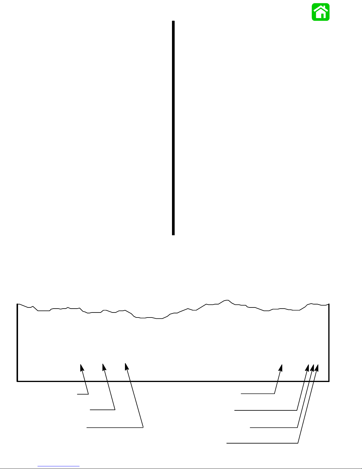
Page Numbering
Two number groups appear at the bottom of each
page. The example below is self-explanatory.
2. Connect a hoist of suitable strength to the lifting
eye.
EXAMPLE:
90-826148 R1 JANUARY 1993
LOWER UNIT - 6A-7
Revision No. 1
Month of Printing
Year of Printing
Section Description
Section Number
Part of Section Letter
Page Number
ii 90-822900R3 DECEMBER 1997
Page 4

Service Manual Outline
Section 1 - Important Information
A - Specifications
B - Maintenance
C - General Information
D - Outboard Installation
Section 2 - Electrical
A - Ignition
B - Charging & Starting System
C - Timing, Synchronizing & Adjusting
D - Wiring Diagrams
Section 3 - Fuel System
A - Fuel Pump
B - Carburetor
C - Fuel Injection
D - Oil Injection
E - Emissions
Section 4 - Powerhead
Section 5 - Mid-Section
A - Clamp/Swivel Brackets & Drive Shaft Housing
B - Power Trim
Section 6 - Lower Unit
A - Right Hand Rotation
B - Left Hand Rotation
Section 7 - Attachments/Control Linkage
Important
Information
1
Electrical
2
Fuel System
3
Powerhead
4
Mid-Section
5
Lower Unit
6
Attachments/
Control Linkage
7
90-822900R3 DECEMBER 1997
iii
Page 5

IMPORTANT
INFORMATION
1
A
SPECIFICATIONS
Page 6

Table of Contents
Master Specifications 1A-1. . . . . . . . . . . . . . . . . . . . . . . .
Page
90-822900R3 DECEMBER 19971A-0 - IMPORTANT INFORMATION
Page 7

Master Specifications
Model 3 Litre Work/225 Carb/225 EFI/250EFI
HORSEPOWER
(KW)
OUTBOARD
WEIGHT
CYLINDER
BLOCK
STROKE Length (All Models) 3.00 in. (76.2mm)
CYLINDER
BORE
PISTON Piston Type
Model 3 Litre
Model 225 Carb
Model 225 EFI
Model 250 EFI
3 Litre/225 Carb
– 20 in. (50.8cm) Shaft
– 25 in. (63.5cm) Shaft
– 30 in. (76.2cm) Shaft
225 EFI/250 EFI
– 20 in. (50.8cm) Shaft
– 25 in. (63.5cm) Shaft
– 30 in. (76.2cm) Shaft
Type
Displacement
Diameter (Std)
Taper/Out of Round/Wear Maximum
Bore Type
Standard
225 (167.8)
225 (167.8)
225 (167.8)
250 (186.5)
440.0 lbs. (199.8kg)
445.0 lbs. (202.0kg)
461.0 lbs. (209.3kg)
450.0 lbs. (204.1kg)
455.0 lbs. (206.4kg)
471.0 lbs. (213.6kg)
V–6 Cylinder, Two Cycle, Loop Charged
185.9 cu. in. (3047cc)
3.6265 in. (92.1131mm)
0.003 in. (0.076mm)
Cast Iron
Aluminum
3.621 in. ± .0005 in. (91.973mm ±
0.0127mm)
COMPRESSION All Models – Using a fully charged
battery, throttle shutters wide open
and cylinder block warm
REEDS Reed Stand 0pen (Max.) 0.020 in. (0.50mm)
MID
SECTION
Power Trim (Total Tilt Range)
Power Trim (Tilt Range)
Steering Pivot Range
Tilt Pin Adjustment Positions
Allowable Transom Thickness
Variance between cylinders should not
exceed 15 psi (102.7 kPa)
2-3/8 in. (6.03cm) Maximum
90 – 110 psi
(616.3 – 753.5 kPa)
75°
20°
60°
5
90-822900R3 DECEMBER 1997 IMPORTANT INFORMATION - 1A-1
Page 8

Model 3 Litre Work/225 Carb/225 EFI/250EFI
GEAR
HOUSING
Gear Ratio
1994 Standard Ratio All Models
1995/1996 Gear Ratios All Models
Optional High Altitude Ratio
(Right Hand Rotation)
3 Litre Work (All Shaft Lengths)
225 Carb (20 in. Shaft Length)
225 Carb (25 in./30 in. Length)
225 EFI (All Shaft Lengths)
250 EFI (All Shaft Lengths)
Gearcase Capacity
Pinion Height
Forward Gear Backlash
– 1.75:1/1.87:1
Reverse Gear Backlash
– Standard Rotation
– Counter Rotation
Water Pressure @ RPM
– @ Idle
– @ 5000 RPM
1.64:1 17/28 Teeth
Service Replacement Ratio for 1.64:1 is
1.62:1 13/21 Teeth
1.87:1 15/28 Teeth
1.75:1 12/21 Teeth
1.75:1
1.75:1
1.75:1
1.75:1
28.0 fl. oz. (828.0ml)
0.025 in. (0.64mm)
.
0.017 in. – 0.028 in. (0.43mm – 0.71mm)
0.028 in. to 0.052 in. (0.71mm to
1.32mm)
0.040 in. – 0.060 in. (1.0mm – 1.52mm)
1-1/2 – 4-1/2 psi (10.3 – 30.8kPa)
8 – 10 psi (54.8 – 68.5kPa) Minimum
FUEL
SYSTEM
STARTING
SYSTEM
IGNITION
SYSTEM
Fuel
Recommended Gasoline
Recommended Oil
Gasoline/Oil Ratio
Fuel Pressure – @ Idle
– @ WOT
Manual Start – All Models
Electric Start – All Models
Starter Draw (Under Load)
Starter Load (No Load)
Minimum Brush Length
Battery Rating
Type
Spark Plug Type
1994 – 1996 S/N 0D280813 0G437999 3 Litre Work/225 Carb
1997 S/N 0G438000 and UP
3 Litre Work/225 Carb
1994/95/96/97 225 EFI/250EFI
Spark Plug Gap
NGK BPZ8H-N-10
Champion QL77CC
Gasoline w/Oil Injection
Unleaded 87 Octane Minimum
Quicksilver TC-W3 2 Cycle Outboard Oil
50:1
2 psi (13.7kPa)
8 psi (54.8kPa)
Emergency Start Rope
165 Amperes
25 Amperes
0.25 in. (65.4mm)
630 Marine Cranking Amps (MCA)
or 490 Cold Cranking Amps (CCA)
Capacitor Discharge
NGK BPZ8H-N-10
Champion QL77CC
Champion QL77CC
0.040 in. (1.0mm)
0.035 in. (0.89mm)
CHARGING
Alternator Output (Regulated)
SYSTEM
Brush Length
30 Amperes @ 750 RPM
60 Amperes @ 2000 RPM
Std. Exposed Length: 0.413 in. (10.5mm)
Min. Exposed Length: 0.059 in. (1.5mm)
90-822900R3 DECEMBER 19971A-2 - IMPORTANT INFORMATION
Page 9

Model 3 Litre Work/225 Carb/225 EFI/250EFI
F
U
E
L
I
N
J
E
C
T
I
O
N
OIL
INJECTION
Idle RPM
– Model 225 EFI/250 EFI
Wide Open Throttle (WOT) RPM
– Model 225 EFI
– Model 250 EFI
Float Adjustment (Vapor Separator)
Float Level
Injectors
– All Models (Quantity)
– Fuel ECU Receives Signal from:
– #2 Primary Ignition Circuit
– #4 Primary Ignition Circuit
– #6 Primary Ignition Circuit
Line Pressure @ Injectors
Recommended Oil
Oil Tank Capacity (in boat)
Approx. Time
– Model 225/250
Reserve Capacity/Approx. Time
Output @ 1500 RPM for 3 Minutes
with Pump @ Full Open
650 ± 50
5000 – 5800
5000 – 5800
Preset @ Factory
6
#1 and #2 Injectors (WHITE Lead)
#3 and #4 Injectors (DARK BLUE Lead)
#5 and #6 Injectors (YELLOW Lead)
34 psi – 36 psi (234kPa – 248kPa)
Quicksilver TC-W3
3 gal. (11.4Liter)
6.0 hrs. Approx.
1.5 qt. (1.45 Liter) 30 – 35 min.
31.5cc @ 1500 RPM
90-822900R3 DECEMBER 1997 IMPORTANT INFORMATION - 1A-3
Page 10

Model 3 Litre Work/225 Carb/225 EFI/250EFI
C
A
R
B
U
R
E
T
O
R
Model 3 Litre Work
Idle RPM
Wide Open Throttle (WOT) RPM
Idle Mixture Screw Adjustment
Float Adjustment
WMV 6
– Cylinder #1
– Main Jet
– Idle Jet
– Vent Jet
650 ± 50
5000 – 5500
1-1/2±1/4
Float is Level with top of Bowl w/Bowl In-
verted
.078
.042
.080
– Cylinder #2
– Main Jet
– Idle Jet
– Vent Jet
.078
.042
.080
– Cylinder #3
– Main Jet
– Idle Jet
– Vent Jet
.080
.056
.080
– Cylinder #4
– Main Jet
– Idle Jet
– Vent Jet
.078
.018
.080
– Cylinder #5
– Main Jet
– Idle Jet
– Vent Jet
– Cylinder #6
– Main Jet
– Idle Jet
– Vent Jet
.088
.056
.080
.078
.018
.080
90-822900R3 DECEMBER 19971A-4 - IMPORTANT INFORMATION
Page 11

Model 3 Litre Work/225 Carb/225 EFI/250EFI
C
A
R
B
U
R
E
T
O
R
Model 3 Litre Work
Idle RPM
Wide Open Throttle (WOT) RPM
Idle Mixture Screw Adjustment
Float Adjustment
WMV 11
– Cylinder #1
– Main Jet
– Idle Jet
– Vent Jet
650 ± 50
5000 – 5500
1-1/2±1/4
Float is Level with top of Bowl w/Bowl In-
verted
.082
.040
.080
– Cylinder #2
– Main Jet
– Idle Jet
– Vent Jet
.082
.046
.080
– Cylinder #3
– Main Jet
– Idle Jet
– Vent Jet
.082
.058
.080
– Cylinder #4
– Main Jet
– Idle Jet
– Vent Jet
.086
.048
.080
– Cylinder #5
– Main Jet
– Idle Jet
– Vent Jet
– Cylinder #6
– Main Jet
– Idle Jet
– Vent Jet
.082
.054
.080
.082
.048
.080
90-822900R3 DECEMBER 1997 IMPORTANT INFORMATION - 1A-5
Page 12

Model 3 Litre Work/225 Carb/225 EFI/250EFI
C
A
R
B
U
R
E
T
O
R
Model 225
Idle RPM
Wide Open Throttle (WOT) RPM
Idle Mixture Screw Adjustment
Float Adjustment
WMV 7
– Cylinder #1
– Main Jet
– Idle Jet
– Vent Jet
650 ± 50
5000 – 5500
1-1/2±1/4
Float is Level with top of Bowl w/Bowl In-
verted
.086
.038
.080
– Cylinder #2
– Main Jet
– Idle Jet
– Vent Jet
.086
.038
.080
– Cylinder #3
– Main Jet
– Idle Jet
– Vent Jet
.088
.070
.080
– Cylinder #4
– Main Jet
– Idle Jet
– Vent Jet
.088
.020
.080
– Cylinder #5
– Main Jet
– Idle Jet
– Vent Jet
.088
.070
.080
– Cylinder #6
– Main Jet
– Idle Jet
– Vent Jet
.088
.032
.080
90-822900R3 DECEMBER 19971A-6 - IMPORTANT INFORMATION
Page 13

Model 3 Litre Work/225 Carb/225 EFI/250EFI
C
A
R
B
U
R
E
O
R
Model 225
Idle RPM
Wide Open Throttle (WOT) RPM
Idle Mixture Screw Adjustment
Float Adjustment
Float is Level with top of Bowl w/Bowl In-
650 ± 50
5000 – 5500
1-1/2±1/4
verted
WMV 13
T
– Cylinder #1
– Main Jet
– Idle Jet
– Vent Jet
.084
.046
.082
– Cylinder #2
– Main Jet
– Idle Jet
– Vent Jet
.082
.060
.082
– Cylinder #3
– Main Jet
– Idle Jet
– Vent Jet
.084
.054
.086
– Cylinder #4
– Main Jet
– Idle Jet
– Vent Jet
.086
.052
.086
– Cylinder #5
– Main Jet
– Idle Jet
– Vent Jet
.084
.058
.082
– Cylinder #6
T
M
– Main Jet
– Idle Jet
– Vent Jet
Idle Timing
I
Maximum BTDC
@ W.O.T (5000 RPM or Above)
.082
.052
.082
4° – 8° ATDC
I
N
G
MODEL 3 LITRE WORK/225 CARB
MODEL 225 EFI
MODEL 250 EFI
19° BTDC @ 5000 RPM
24° BTDC @ 5500 RPM
24° BTDC @ 5000 RPM
24° BTDC @ 5800 RPM
24° BTDC @ 5000 RPM
28° BTDC @ 5800 RPM
NOTE: Timing specifications listed are for 1998 model year engines. Refer to timing decal on engine for previous
model year timing specifications.
90-822900R3 DECEMBER 1997 IMPORTANT INFORMATION - 1A-7
 Loading...