

Page 1

30 - 60 HP Outboard
Installation Manual
NOTICE to INSTALLER
After completing assembly, these
instructions should be placed with the
product for the owner’s future use.
IMPORTANT: If the boat is to be water tested, the
operator should be familiar with the operation
procedures in the Operation and Maintenance
Manual.
Table of Contents
Boat Horsepower Capacity
U.S. COAST GUARD CAPACITY
MAXIMUM HORSEPOWER XXX
MAXIMUM PERSON
CAPACITY (POUNDS) XXX
MAXIMUM WEIGHT
CAPACITY XXX
Do not overpower or overload the boat. Most boats
will carry a required capacity plate indicating the maximum acceptable power and load as determined by
the manufacturer following certain federal guidelines.
If in doubt, contact your dealer or the boat manufacturer.
Electric Fuel Pump 1. . . . . . . . . . . . . . . . . . . . . . . . . .
Boat Horsepower Capacity 1. . . . . . . . . . . . . . . . . . .
Outboard Remote Control 1. . . . . . . . . . . . . . . . . . . .
Selecting Accessories For The Outboard 1. . . . . . .
Installation Specifications 2. . . . . . . . . . . . . . . . . . . . .
Lifting Outboard 2. . . . . . . . . . . . . . . . . . . . . . . . . . . . .
Steering Cable 3. . . . . . . . . . . . . . . . . . . . . . . . . . . . . .
Steering Cable Seal 3. . . . . . . . . . . . . . . . . . . . . . . . .
Steering Link Rod 3. . . . . . . . . . . . . . . . . . . . . . . . . . .
Installing Outboard Non Thumb Screw Models 4. .
Installing Outboard Thumb Screws Models 5. . . . .
Wiring Harness 6. . . . . . . . . . . . . . . . . . . . . . . . . . . . .
Battery Cable Connections 7. . . . . . . . . . . . . . . . . . .
Shift and Throttle Cable 30-40 Hp (2-Cyl.) 8. . . . . .
Shift and Throttle Cable 40-50 Hp (3-Cyl.) 10. . . . .
Shift and Throttle Cable 60 Hp 12. . . . . . . . . . . . . . .
Oil Injection Set Up 14. . . . . . . . . . . . . . . . . . . . . . . . .
Installing Remote Oil Tank (If Equipped) 14. . . . . . .
WARNING
Using an outboard that exceeds the maximum
horsepower limit of a boat can: 1. cause loss of
boat control 2. place too much weight at the transom altering the designed flotation characteristics of the boat or 3. cause the boat to break apart,
particularly around the transom area. Overpowering a boat can result in serious injury , death, or
boat damage.
Start in Gear Protection
The remote control connected to the outboard must
be equipped with a start-in-gear protection device.
This prevents the engine from starting in gear.
WARNING
Avoid serious injury or death from a sudden unexpected acceleration when starting your engine.
The design of this outboard requires that the remote control used with it must have a built in
start-in-gear protection device.
Propeller Installation 15. . . . . . . . . . . . . . . . . . . . . . . .
Trim-In Stop Adjustment – Power Trim Models 16.
Trim Tab Adjustment 16. . . . . . . . . . . . . . . . . . . . . . . .
Electric Fuel Pump
If an electric fuel pump is used, the fuel pressure must
not exceed 4 psig at the engine. If necessary, install
a pressure regulator to regulate the pressure.
Selecting Accessories For
The Outboard
Genuine Quicksilver Parts and Accessories have
been specifically designed and tested for this outboard.
Some accessories not manufactured or sold by
Quicksilver are not designed to be safely used with
this outboard or outboard operating system. Acquire
and read the installation, operation, and maintenance
manuals for all selected accessories.
90-10175010 100- 1 -Printed in U.S.A.
Page 2
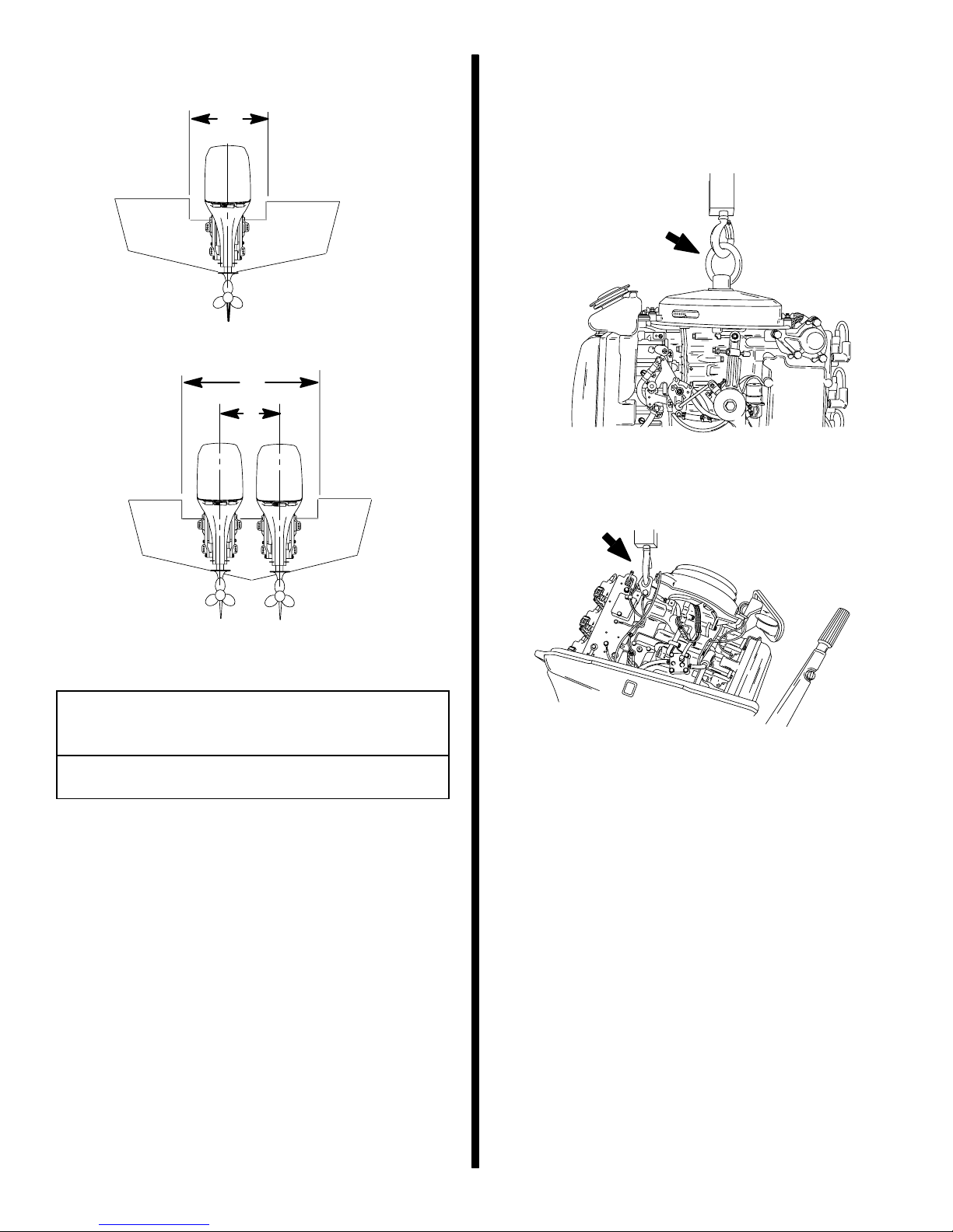
Installation Specifications
a
a
b
Lifting Outboard
Electric Start Models – Remove plastic cap from fly-
wheel hub. Thread lifting ring into flywheel a minimum
of 5 turns. Replace plastic cap after installation.
Manual Start Models – Use lifting eye.
a – Transom Opening – Minimum
Single Engine – 19 in. (483 mm)
Dual Engines – 40 in. (1016 mm)
b – Engine Center Line For Dual Engine
22-1/2 in. (572 mm) Minimum
- 2 -
Page 3
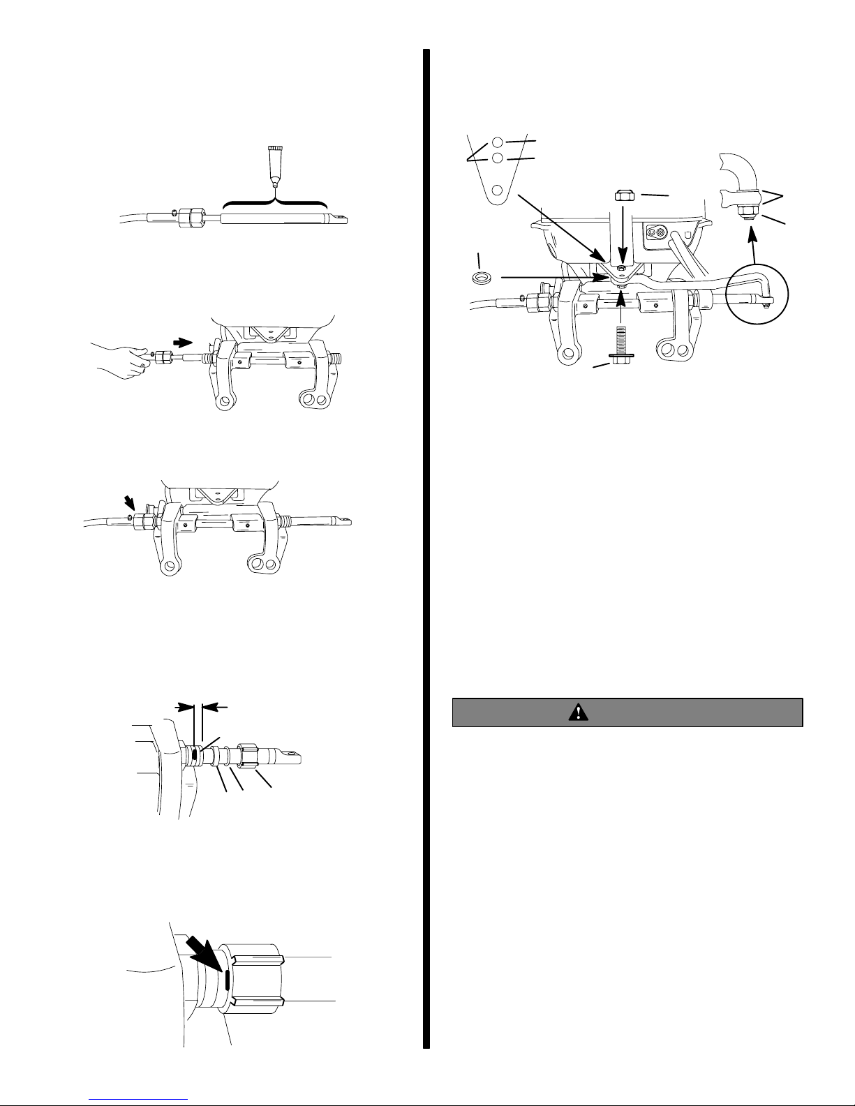
Steering Cable
Steering Link Rod
STARBOARD SIDE ROUTED CABLE
1. Lubricate the entire cable end.
a
a - Quicksilver 2-4-C Marine Lubricant with Teflon
2. Insert steering cable into tilt tube.
3. Torque nut to 35 lb. ft. (47.5 N·m).
1. Install steering link rod per illustration.
60 Hp
f
30-40-50 Hp
b
c
a
a - Special Bolt (10-90041) Torque to 20 lb. ft.(27.1 N·m)
b - Nylon Insert Locknut (11-34863) Torque to
20 lb. ft.(27.1 N·m)
c - Spacer (12-71970)
d - Flat Washer (2)
e - Nylon Insert Locknut (11-34863) Tighten Locknut Until it
Seats, Then Back Nut Off 1/4 Turn
f - Use Correct Hole
d
e
Steering Cable Seal
1. Mark tilt tube 1/4 in. (6.4 mm) from end. Install
seal components.
1/4 in. (6.4mm)
a
d
c
b
a - 1/4 In. (6.4 mm) Mark
b - Plastic Spacer
c - O-Ring Seal
d - Cap
2. Thread cap to the mark.
IMPORTANT: The steering link rod that connects
the steering cable to the engine must be fastened
using special bolt (“a” - Part Number 10-90041)
and self locking nuts (“b” & “c” - Part Number
11-34863). These locknuts must never be replaced with common nuts (non locking) as they
will work loose and vibrate off, freeing the link rod
to disengage.
WARNING
Disengagement of a steering link rod can result in
the boat taking a full, sudden, sharp turn. This potentially violent action can cause occupants to be
thrown overboard exposing them to serious injury or death.
- 3 -
Page 4
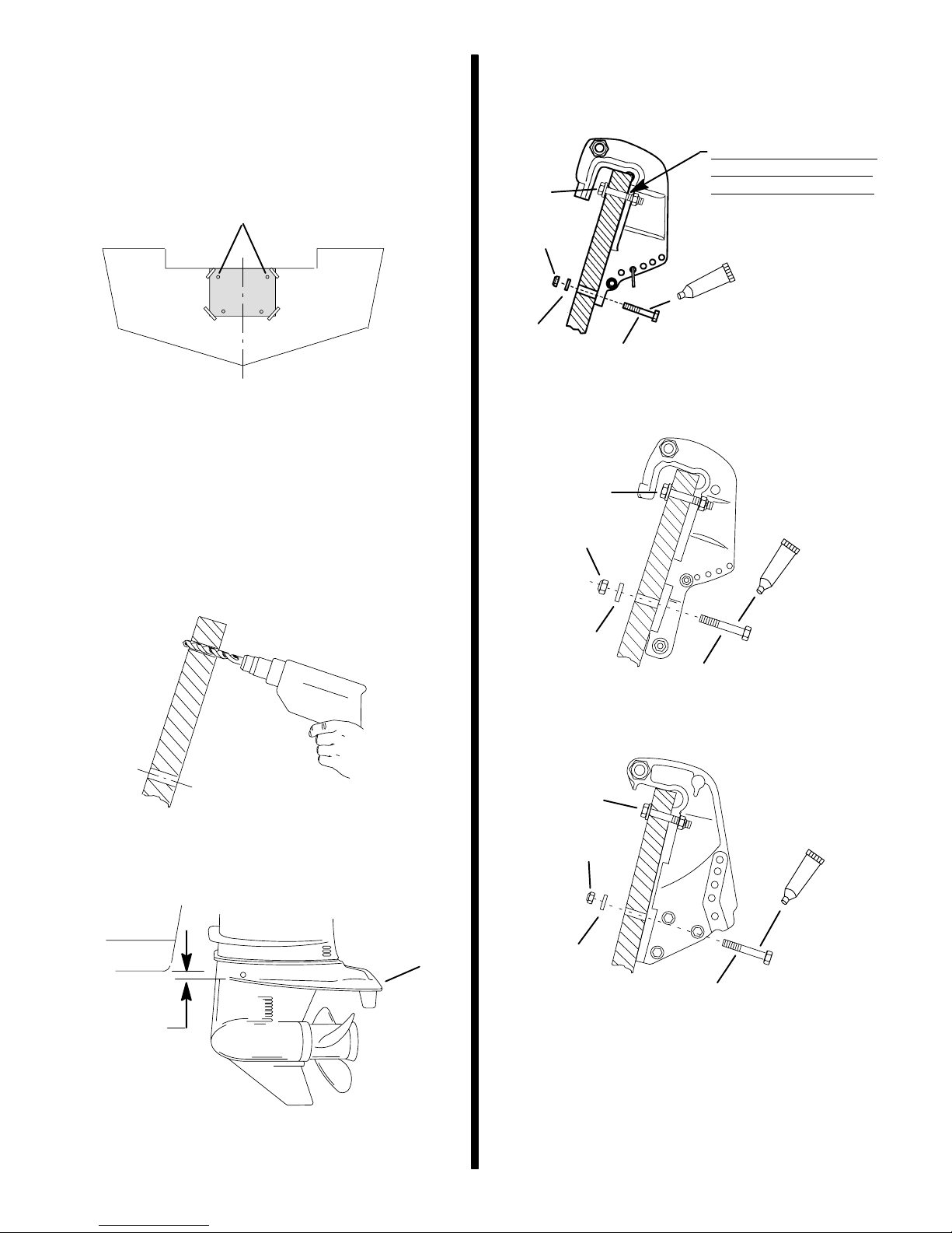
Installing Outboard – Non
Thumb Screw Models
1. Attach (tape) engine mounting template (located
in center on this manual) to boat transom.
NOTE: Drill only the top holes for Type 1
Brackets
6. Fasten outboard with provided mounting hardware shown.
Type 1 Bracket
DRILL Only the Upper
Holes Using Template
a
d
On This Type Bracket.
Mark and drill lower holes
after outboard height is
set.
e
c
b
2. T ype 1 Bracket – 30-40 Hp (2 Cyl.) Short Shaft
Versions – Mark the two upper holes and drill
17/32 in. (13.5mm) holes. Set Outboard height
(Step 5) and Drill two 3/8 in. (9.5mm) lower
mounting holes
3. Type 2 Bracket – 30-40-50 Hp – Mark and drill
four 17/32 in. (13.5mm) mounting holes.
4. Type 3 Bracket – 60 Hp – Mark and drill four
17/32 in. (13.5mm) mounting holes.
5. Install the outboard so that the anti-ventilation
plate is in-line or within 1 in. (25 mm) below the
bottom of the boat.
Type 2 Bracket
a
d
e
c
a
Type 3 Bracket
a
d
e
0 - 1 in.
(0 - 25mm)
a - Anti Ventilation Plate
a
c
a
a - 1/2 In. Diameter Bolts (2)
b - 3/8 In. Diameter Bolts (2)
c - Flat Washers (4)
d - Locknuts (4)
e - Marine Sealer - Apply to Shanks of Bolts, Not Threads
- 4 -
Page 5
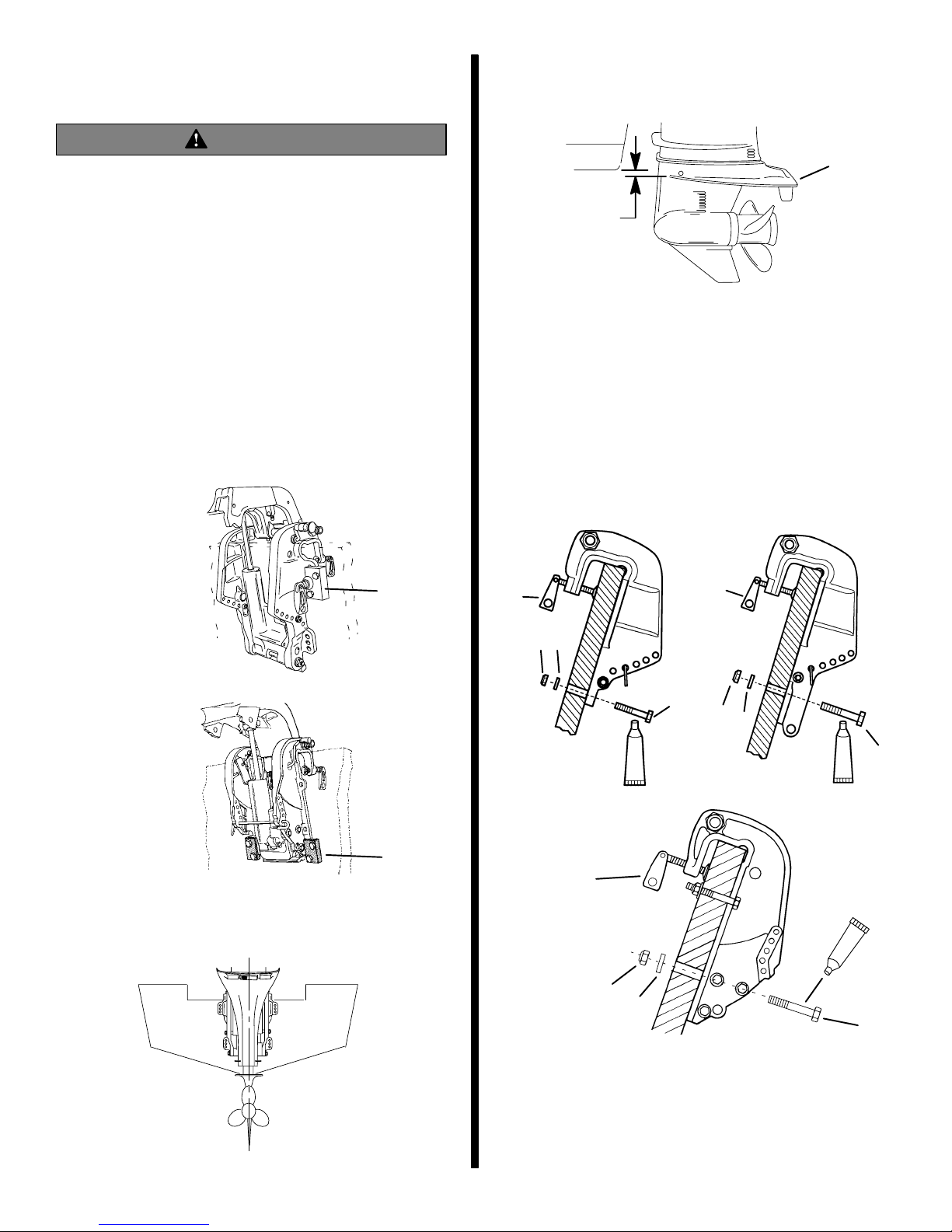
Installing Outboard – Thumb
Screw Models
WARNING
Outboard must be fastened to boat transom one
of two ways: 1. permanently fastened to transom
with thumb screws, and mounting bolts (provided), or 2. secured to the transom using the optional outboard mounting kit (shown below).
Should the outboard strike an underwater object
or be steered into a sharp turn, failure to fasten
outboard correctly to the boat transom with
mounting bolts or optional mounting kit could result in outboard ejecting suddenly off boat transom causing serious injury, death, boat damage,
or loss of outboard.
1. Optional Outboard Mounting kits shown, must be
used if outboard will not be permanently fastened
to the transom with mounting bolts.
30-40-50 Hp
3. Install the outboard so that the anti-ventilation
plate is in-line or within 1 in. (25 mm) below the
bottom of the boat.
a
0 - 1 in
(0 - 25mm)
a - Anti Ventilation Plate
4. Type 1 Bracket – 30-40 Hp – Mark and drill two
3/8 in. (9.5mm) lower mounting holes.
5. Type 2 Bracket – 30-50 Hp – Mark and drill two
17/32 in. (13.5mm) lower mounting holes.
6. Type 3 Bracket – 55-60 Hp – Mark and drill four
17/32 in. (13.5mm) mounting holes.
7. Fasten outboard with provided mounting hardware shown.
Type 1 Bracket
Type 2 Bracket
55-60 Hp
a - Outboard Mounting Kit Part No. 812432A4
b - Outboard Mounting Kit Part No. 812432A5
2. Center outboard on the transom.
a
g
e
d
g
b
e
d
a
f
Type 3 Bracket
f
b
g
f
e
d
c
a - 1/2 In. Diameter Bolts (2)
b - 3/8 In. Diameter Bolts (2)
c - 1/2 In. Diameter Bolts (4)
d - Flat Washers
e - Locknuts
f - Marine Sealer - Apply to Shanks of Bolts Not Threads
g - Thumb Screws - Tighten Securely
- 5 -
Page 6

Wiring Harness
IMPORTANT: Warning Horn Requirement – The
remote control or key switch assembly must be
wired with a warning horn. This warning horn is
used with the engine warning system.
1. Route wiring harness into bottom cowl.
30-40 Hp (2 Cyl.)
2. Connect wiring. Place harness into the holder.
30-40 Hp (2 Cyl.)
40-50 Hp (3 Cyl.)
60 Hp
BLU/WHT
GRN/WHT
TAN
BRN/WHT
40-50-60 Hp (3 Cyl.)
BLU/WHT
GRN/WHT
a
a - Power Trim Connections
- 6 -
BLU/WHT
GRN/WHT
TAN
BRN/WHT
BLU/WHT
GRN/WHT
a
Page 7

30-40 HP (2 CYL.) MANUAL START MODELS
USING QUICKSILVER 2000 SERIES SIDE
MOUNT REMOTE CONTROL
1. Route the remote control harness (a) around the
back of the engine block as shown. Position the
harness so that the harness will not interfere with
shift and throttle operation.
Battery Cable Connections
SINGLE OUTBOARD
a
(+)
b
a
2. Connect the black wire (a) to engine ground and
the black/yellow wire (b) to the black/yellow engine wire.
a
ENGINE GROUND
a
BLK/YEL
b
BLK/YEL
(–)
a - Red Sleeve (Positive)
b - Black Sleeve (Negative)
c - Starting Battery
c
DUAL OUTBOARD
1. Connect a common ground cable (wire size same
as engine battery cables) between negative (–)
terminals on starting batteries.
(–)
d
(–)
d - Ground Cable (Same Wire Size As Engine Battery Cable –
Connect Between Negative (–) Terminals
- 7 -
Page 8

Shift and Throttle Cable
30 and 40 Hp (2 Cyl.) Models
3. Push-in on the cable end until resistance is felt.
Adjust the cable ba r re l ( b) t o at t ai n t he measured
distance “a” taken in Step 2.
Install cables into the remote control following the
instructions provided with the remote control.
NOTE: Install the shift cable to the engine first. The
shift cable is the first cable to move when the remote
control handle is moved out of neutral.
30-40 Hp (2 Cyl.) – Shift Cable
Installation
1. Position remote control and outboard into neutral.
N
2. Measure distance “a” between mounting pin and
middle of the barrel holder.
4. Place cable barrel into the bottom hole in the barrel holder. Fasten cable to pin with retainer.
a
b
a
c
b
a - Distance Between Pin And Middle Of Barrel Holder
b - Mounting Pin
c - Barrel Holder
c
a - Move Cable Barrel To Attain The Measured Distance
Taken In Step 2
b - Cable Barrel
c - Barrel Holder – Place Barrel Into Bottom Hole
d - Retainer
5. Check shift cable adjustments as follows:
a. Shift remote control into forward. The propel-
ler shaft should be locked in gear. If not, adjust
the barrel closer to the cable end.
b. Shift remote control into neutral. The propel-
ler shaft should turn freely without drag. If not,
adjust the b arre l away from the cable end. Repeat steps a and b.
c. Shift remote control into reverse while turning
propeller. The propeller shaft should be
locked in gear. If not, adjust the barrel away
from the cable end. Repeat steps a thru c.
d. Shift remote control back to neutral. The pro-
peller shaft should turn freely without drag. If
not, adjust the barrel closer to the cable end.
Repeat steps a thru d.
d
- 8 -
Page 9

30-40 Hp (2 Cyl.) – Throttle Cable
Installation
1. Position remote control into neutral.
4. Check throttle cable adjustment as follows:
a. Shift outboard into gear a few times to activate
the throttle linkage. Make sure to rotate the
propeller shaft while shifting into reverse.
N
2. Install cable to the throttle lever. Secure with retainer.
b
a
a - Throttle Cable
b - Retainer
3. Adjust the cable barrel so that the installed throttle
cable will hold the throttle arm against the stop.
F
b. Return remote control to neutral. Place a thin
piece of paper between throttle arm and idle
stop. Adjustment is correct when the paper
can be removed without tearing, but has
some drag on it. Readjust cable barrel if necessary.
N
R
b
a
a
c
b
a - Cable Barrel – Adjust To Hold Throttle Arm Against Stop
b - Throttle Arm
c - Barrel Holder – Place barrel Into Top Hole
a - Throttle Arm
b - Idle Stop
5. Lock the barrel holder in place with the cable
latch.
- 9 -
Page 10

Shift and Throttle Cable
40 and 50 Hp (3 Cyl.) Models
3. Push-in on the cable end until resistance is felt.
Adjust the cable ba r re l ( b) t o at t ai n t he measured
distance “a” taken in Step 2.
Install cables into the remote control following the
instructions provided with the remote control.
NOTE: Install the shift cable to the engine first. The
shift cable is the first cable to move when the remote
control handle is moved out of neutral.
40-50 Hp (3 Cyl.) – Shift Cable
Installation
1. Position remote control and outboard into neutral.
N
2. Measure distance “a” between mounting pin and
middle of the barrel holder.
4. Place cable barrel into the bottom hole in the barrel holder. Fasten cable to pin with retainer.
a
b
a
c
b
a - Distance Between Pin And Middle Of Barrel Holder
b - Mounting Pin
c - Barrel Holder
c
a - Move Cable Barrel To Attain The Measured Distance
Taken In Step 2
b - Cable Barrel
c - Barrel Holder – Place Barrel Into Bottom Hole
d - Retainer
5. Check shift cable adjustments as follows:
a. Shift remote control into forward. The propel-
ler shaft should be locked in gear. If not, adjust
the barrel closer to the cable end.
b. Shift remote control into neutral. The propel-
ler shaft should turn freely without drag. If not,
adjust the b arre l away from the cable end. Repeat steps a and b.
c. Shift remote control into reverse while turning
propeller. The propeller shaft should be
locked in gear. If not, adjust the barrel away
from the cable end. Repeat steps a thru c.
d. Shift remote control back to neutral. The pro-
peller shaft should turn freely without drag. If
not, adjust the barrel closer to the cable end.
Repeat steps a thru d.
d
- 10 -
Page 11

40-50 Hp (3 Cyl.) – Throttle Cable
Installation
1. Position remote control into neutral.
4. Check throttle cable adjustment as follows:
a. Shift outboard into gear a few times to activate
the throttle linkage. Make sure to rotate the
propeller shaft while shifting into reverse.
N
2. Install cable to the throttle lever. Tighten locknut,
then back-off the locknut 1/4 turn.
a
b
c
a - Throttle Cable
b - Nylon Washer
c - Locknut – Tighten Locknut, Then Back-Off The Locknut 1/4
Turn
F
N
R
b. Return remote control to neutral. Place a thin
piece of paper between idle adjustment screw
and idle stop. Adjustment is correct when the
paper can be removed without tearing, but
has some drag on it. Readjust cable barrel if
necessary.
b
a
3. Adjust the cable barrel so that the installed throttle
cable will hold the idle adjustment screw against
the stop.
a
c
b
a - Idle Adjustment Screw
b - Idle Stop
5. Lock the barrel holder in place with the cable
latch.
a - Cable Barrel – Adjust To Hold Idle Adjustment Screw
Against Stop
b - Idle Adjustment Screw
c - Barrel Holder – Place barrel Into Top Hole
- 11 -
Page 12

Shift and Throttle Cable
60 Hp Models
3. Push-in on the cable end until resistance is felt.
Adjust the cable ba r re l ( b) t o at t ai n t he measured
distance “a” taken in Step 2.
Install cables into the remote control following the
instructions provided with the remote control.
NOTE: Install the shift cable to the engine first. The
shift cable is the first cable to move when the remote
control handle is moved out of neutral.
60 Hp – Shift Cable Installation
1. Position remote control and outboard into neutral.
N
2. Measure distance “a” between mounting pin and
middle of the barrel holder.
4. Place cable barrel into the bottom hole in the barrel holder. Fasten cable to pin with locknut.
a
b
d
a
c
a - Distance Between Pin And Middle Of Barrel Holder
b - Mounting Pin
c - Barrel Holder
e
c
a - Move Cable Barrel To Attain The Measured Distance
Taken In Step 2
b
b - Cable Barrel
c - Barrel Holder – Place Barrel Into Bottom Hole
d - Nylon Washer
e - Locknut – Tighten Locknut, Then Back-Off The Locknut 1/4
Turn
5. Check shift cable adjustments as follows:
a. Shift remote control into forward. The propel-
ler shaft should be locked in gear. If not, adjust
the barrel closer to the cable end.
b. Shift remote control into neutral. The propel-
ler shaft should turn freely without drag. If not,
adjust the b arre l away from the cable end. Repeat steps a and b.
c. Shift remote control into reverse while turning
propeller. The propeller shaft should be
locked in gear. If not, adjust the barrel away
from the cable end. Repeat steps a thru c.
d. Shift remote control back to neutral. The pro-
peller shaft should turn freely without drag. If
not, adjust the barrel closer to the cable end.
Repeat steps a thru d.
- 12 -
Page 13

60 Hp – Throttle Cable Installation
1. Position remote control into neutral.
N
4. Check throttle cable adjustment as follows:
a. Shift outboard into gear a few times to activate
the throttle linkage. Make sure to rotate the
propeller shaft while shifting into reverse.
2. Install cable to the throttle lever. Tighten locknut,
then back-off the locknut 1/4 turn.
a
b
c
a - Throttle Cable
b - Nylon Washer
c - Locknut – Tighten Locknut, Then Back-Off The Locknut 1/4
Turn
3. Adjust the cable barrel so that the installed throttle
cable will hold the idle adjustment screw against
the stop.
F
N
R
b. Return remote control to neutral. Place a thin
piece of paper between idle adjustment screw
and idle stop. Adjustment is correct when the
paper can be removed without tearing, but
has some drag on it. Readjust cable barrel if
necessary.
b
a
b
a
c
a - Cable Barrel – Adjust To Hold Idle Adjustment Screw
Against Stop
b - Idle Adjustment Screw
c - Barrel Holder – Place Barrel Into Top Hole
a - Idle Adjustment Screw
b - Idle Stop
5. Lock the barrel holder in place with the cable
latch.
- 13 -
Page 14

Oil Injection Set Up
Installing Remote Oil Tank
1.Fill engine oil tank with oil.
2.Inspect the oil pump inlet hose (a) for air bubbles.
If air exists, place a shop towel below the oil pump
and loosen bleed screw (c) four turns. Allow oil to
flow out of the bleed hole until air is removed from
the hose.
3.Inspect the oil pump outlet oil hose (b) for air
bubbles. If air exists, disconnect link rod from oil
pump. Start engine and run at 1000 to 1500 RPM.
Rotate (and hold) the pump arm full clockwise until the air is purged out of the hose.
b
a
(If Equipped)
MOUNTING OIL TANK
1.Mount the remote oil tank in the boat. The tank
should be restrained from moving. Use the oil
tank hold down kit provided.
2.Arrange the hoses so they will not get pinched,
kinked, or stretched during operation.
NOTE: A Quicksilver Accessory oil hose extension kit
(41729A3) is available.
c
e
a-Inlet Hose
b-Outlet Hose
c-Bleed Screw – Torque to 15 lb. in. (N·m
d-Link Rod
e-Pump Arm
4.Reconnect the link rod. Set carburetor linkage at
idle position. Alignment marks should line-up. If
necessary, adjust link rod.
)
d
CONNECTING REMOTE OIL TANK HOSES
3.Remove shipping caps from oil hose fittings and
connect hoses as shown. Fasten hose with stastrap.
Oil Hoses From Engine
Black
Black with
Blue Stripe
Black with
Blue Stripe
Oil Hoses From Remote Oil Tank
Black
a
a-Sta-Strap – Secure Hose Connections
4.Remove the filler cap and fill remote tank with oil. Oil
tank capacity is 3 gallons (11.5 liters). Reinstall filler
cap and tighten securely.
IMPORTANT: Always make sure the oil tank caps
are threaded on tight. An air leak will prevent oil
flow to the engine.
- 14 -
Page 15

Propeller Installation
Propeller Installation (Cont.)
3-1/4 in. (83mm) Diameter Gear Case
WARNING
If the propeller shaft is rotated while the engine is
in gear, there is the possibility that the engine will
crank over and start. To prevent this type of accidental engine starting and possible serious injury caused from being struck by a rotating propeller, always shift outboard to neutral position and
remove spark plug leads when you are servicing
the propeller.
Flo-Torq I Drive Hub Propellers
cb
a - Forward Thrust Hub
b - Propeller Nut Retainer
c - Propeller Nut
Flo-Torq II Drive Hub Propellers
c
d
e
a
4-1/4 in. (108 mm) Diameter Gear
Case
WARNING
If the propeller shaft is rotated while the engine is
in gear, there is the possibility that the engine will
crank over and start. To prevent this type of accidental engine starting and possible serious injury caused from being struck by a rotating propeller, always shift outboard to neutral position and
remove spark plug leads when you are servicing
the propeller.
Flo-Torq I Drive Hub Propellers
b
e
a - Forward Thrust Hub
b - Continuity Washer
c - Thrust Hub
d - Propeller Nut Retainer
e - Propeller Nut
Flo-Torq II Drive Hub Propellers
d
c
a
b
a - Forward Thrust Hub
b - Replaceable Drive Sleeve
c - Rear Thrust Hub
d - Propeller Nut Retainer
e - Propeller Nut
5. Tighten propeller nut to 55 lb.ft. (75 N·m). Bend
tabs against nut.
a
b
a - Propeller Nut - Torque To 55 lb. ft. (75 N·m)
b - Bend Tabs Against Nut
a
e
a - Forward Thrust Hub
b - Replaceable Drive Sleeve
c - Rear Thrust Hub
d - Propeller Nut Retainer
e - Propeller Nut
6. Tighten propeller nut to 55 lb.ft. (75 N·m). Bend
tabs into grooves.
c
d
b
a
a
b
b
a - Propeller Nut - Torque To 55 lb. ft. (75 N·m)
b - Bend Tabs Into Grooves
- 15 -
Page 16

Trim-In Stop Adjustment –
Trim Tab Adjustment
Power Trim Models
40-50 Hp
If an adjustment is required to the the trim-in stop, reposition the tilt stop pins as follows:
1. Lock the outboard in the full tilt position.
2. Remove bottom pivot pin.
3. Swing the power trim system outward to gain access to the tilt stop pins. Reposition the tilt stop
pins in the desired holes.
4. Reinstall the bottom pivot pin. Torque pivot pin
nuts to 18 lb. ft. (24.4 N·m).
a
a
The trim tab can be adjusted within limits to help to
compensate for steering torque.
Adjust trim tab as follows:
1. If boat tends to pull to the right, move the rear
edge of the trim tab to the right.
2. If boat tends to pull to the left, move the rear edge
of the trim tab to the left.
NOTE: Trim tab adjustment will have little effect reducing steering torque if the the anti-ventilation plate
is raised 2 inches (50mm) or more above the boat bottom.
b
28216
a Tilt Stop Pins
b - Bottom Pivot Pin
60 Hp
If an adjustment is required, purchase a stainless
steel tilt pin (P/N 17-49930A1) and insert it through
whatever pin hole is desired. The non-stainless steel
shipping bolt should not be used in this application
other than on a temporary basis.
a
a - Tilt Pin
28216
- 16 -
 Loading...