

Page 1

for your purchase of one of the finest outboards available.
You have made a sound investment in boating pleasure.
Your outboard has been manufactured by Mercury Racing, a unit of Mercury Marine, the world leader in marine
technology and outboard manufacturing since 1939.
These years of experience have been committed to the
goal of producing the finest quality products. This has led
to Mercury Racing’s reputation for strict quality control,
excellence, durability, lasting performance and being the
best at providing after-the-sale support.
Please read this manual carefully before operating your
outboard. This manual has been prepared to assist you
in the operation, safe use and care of your outboard.
All of us at Mercury Racing took pride in building your outboard and wish you many years of happy and safe boating.
Again, thank you for your confidence in Mercury Marine.
300 - PRO MAX 3.0L
Mercury Racing
N7480 County Road “UU”
Fond du Lac, WI 54935-9585
1999 Mercury Marine 90Ć849233000 499
Page 2

0
Page 3

oa
TABLE OF CONTENTS
General Information
Boater ’s Responsibilities 4. . . . . . . . . . . . . . . . . . . . . . . . . . . . . .
Before Operating Your Outboard 4. . . . . . . . . . . . . . . . . . . . . . .
Boat Horsepower Capacity 5. . . . . . . . . . . . . . . . . . . . . . . . . . . .
High-Speed And High-Performance Boat Operation 5. . . . . .
Lanyard Stop Switch 6. . . . . . . . . . . . . . . . . . . . . . . . . . . . . . . . . .
Protecting People In The Water 8. . . . . . . . . . . . . . . . . . . . . . . .
Carbon Monoxide Risk 9. . . . . . . . . . . . . . . . . . . . . . . . . . . . . . . .
Wave And Wake Jumping 11. . . . . . . . . . . . . . . . . . . . . . . . . . . . .
Impact With Underwater Hazards 12. . . . . . . . . . . . . . . . . . . . . .
Selecting Accessories For Your Outboard 14. . . . . . . . . . . . . . .
Safe Boating Suggestions 14. . . . . . . . . . . . . . . . . . . . . . . . . . . . .
Recording Serial Number 16. . . . . . . . . . . . . . . . . . . . . . . . . . . . .
Specifications 17. . . . . . . . . . . . . . . . . . . . . . . . . . . . . . . . . . . . . . . .
Component Identification 18. . . . . . . . . . . . . . . . . . . . . . . . . . . . . .
Propeller Selection 19. . . . . . . . . . . . . . . . . . . . . . . . . . . . . . . . . . .
Transporting
Trailering Boat/Outboard 20. . . . . . . . . . . . . . . . . . . . . . . . . . . . . .
Fuel & Oil
Gasoline Recommendations 21. . . . . . . . . . . . . . . . . . . . . . . . . . .
Oil Recommendation 22. . . . . . . . . . . . . . . . . . . . . . . . . . . . . . . . .
Filling Fuel Tank 23. . . . . . . . . . . . . . . . . . . . . . . . . . . . . . . . . . . . . .
Filling Remote Oil Tank 24. . . . . . . . . . . . . . . . . . . . . . . . . . . . . . .
Filling Engine Mounted Oil Reservoir Tank 24. . . . . . . . . . . . . . .
1
Page 4

oa
TABLE OF CONTENTS
Features & Controls
Remote Control Features 25. . . . . . . . . . . . . . . . . . . . . . . . . . . . .
Warning Horn System 26. . . . . . . . . . . . . . . . . . . . . . . . . . . . . . . .
Power Trim And Tilt 30. . . . . . . . . . . . . . . . . . . . . . . . . . . . . . . . . . .
Power Trim Operation 31. . . . . . . . . . . . . . . . . . . . . . . . . . . . . . . .
Tilting Operation 33. . . . . . . . . . . . . . . . . . . . . . . . . . . . . . . . . . . . .
Manual Tilting 35. . . . . . . . . . . . . . . . . . . . . . . . . . . . . . . . . . . . . . .
Operation
Engine Break-in 37. . . . . . . . . . . . . . . . . . . . . . . . . . . . . . . . . . . . .
Pre-Starting Check List 39. . . . . . . . . . . . . . . . . . . . . . . . . . . . . . .
Operating In Freezing Temperatures 40. . . . . . . . . . . . . . . . . . . .
Operating In Salt Water Or Polluted Water 40. . . . . . . . . . . . . . .
Operating At High Elevations 40. . . . . . . . . . . . . . . . . . . . . . . . . .
Setting Trim Angle While Running Engine at Idle Speed 41. . .
Operating in Shallow Water 41. . . . . . . . . . . . . . . . . . . . . . . . . . . .
Starting The Engine 42. . . . . . . . . . . . . . . . . . . . . . . . . . . . . . . . . .
Gear Shifting 44. . . . . . . . . . . . . . . . . . . . . . . . . . . . . . . . . . . . . . . .
Stopping The Engine 44. . . . . . . . . . . . . . . . . . . . . . . . . . . . . . . . .
Emergency Starting 45. . . . . . . . . . . . . . . . . . . . . . . . . . . . . . . . . .
Maintenance
Outboard Care 47. . . . . . . . . . . . . . . . . . . . . . . . . . . . . . . . . . . . . . .
Submerged Outboard 47. . . . . . . . . . . . . . . . . . . . . . . . . . . . . . . . .
Selecting Replacement Parts For Your Outboard 47. . . . . . . . .
EPA Emissions Regulations 47. . . . . . . . . . . . . . . . . . . . . . . . . . .
Inspection And Maintenance Schedule 48. . . . . . . . . . . . . . . . . .
Flushing the Cooling System 50. . . . . . . . . . . . . . . . . . . . . . . . . .
Top Cowl Removal and Installation 52. . . . . . . . . . . . . . . . . . . . .
Flywheel Cover Removal and Installation 53. . . . . . . . . . . . . . . .
Fuel System 53. . . . . . . . . . . . . . . . . . . . . . . . . . . . . . . . . . . . . . . . .
(continued on next page)
2
Page 5

oa
TABLE OF CONTENTS
Maintenance (con’t.)
Steering Link Rod Fasteners 55. . . . . . . . . . . . . . . . . . . . . . . . . .
Fuse Replacement 56. . . . . . . . . . . . . . . . . . . . . . . . . . . . . . . . . . .
Corrosion Control Anodes 56. . . . . . . . . . . . . . . . . . . . . . . . . . . . .
Propeller Replacement 57. . . . . . . . . . . . . . . . . . . . . . . . . . . . . . . .
Spark Plug Inspection 59. . . . . . . . . . . . . . . . . . . . . . . . . . . . . . . .
Battery Inspection 59. . . . . . . . . . . . . . . . . . . . . . . . . . . . . . . . . . . .
Alternator Drive Belt Tension Adjustment 60. . . . . . . . . . . . . . . .
Lubrication Points 61. . . . . . . . . . . . . . . . . . . . . . . . . . . . . . . . . . . .
Checking Power Trim Fluid 63. . . . . . . . . . . . . . . . . . . . . . . . . . . .
Gear Case Lubricant 65. . . . . . . . . . . . . . . . . . . . . . . . . . . . . . . . .
Storage
Storage Preparation 67. . . . . . . . . . . . . . . . . . . . . . . . . . . . . . . . . .
Troubleshooting
Troubleshooting 70. . . . . . . . . . . . . . . . . . . . . . . . . . . . . . . . . . . . . .
Engine Wiring Diagram
Engine Wiring Diagram 74. . . . . . . . . . . . . . . . . . . . . . . . . . . . . . .
Maintenance Lo g
Maintenance Log 76. . . . . . . . . . . . . . . . . . . . . . . . . . . . . . . . . . . . .
The description and specifications contained herein were in effect
at the time this manual was approved for printing. Mercury Racing,
whose policy is one of continued improvement, reserves the right to
discontinue models at any time, to change specifications, designs,
methods, or procedures without notice and without incurring obligation.
Mercury Marine, Fond du Lac, Wisconsin U.S.A. Litho in U.S.A.
1999, Mercury Marine
The following are registered trademarks of Brunswick Corporation:
AutoBlend, Force, Jet-Prop, Mariner, Merc, Mercathode, MerCruiser, Mercury, Mercury Marine, Mercury Racing, Quicksilver, RideGuide and Thruster
3
Page 6
ob
GENERAL INFORMATION
oba1
Boater’s Responsibilities
The boat driver is responsible for correct and safe operation of the
boat and safety of its occupants and general public. It is strongly recommended that each operator (driver) read and understand this entire manual before operating the outboard.
Be sure at least one additional person on board is instructed in the
basics of starting and operating the outboard and boat handling in
case the driver is unable to operate the boat.
obb1
Before Operating Your Outboard
Read this manual carefully. Safety and operating information that is
practiced along with using good common sense can help prevent
personal injury and product damage. If you have any questions,
contact your dealer.
This manual as well as safety labels posted on the outboard use
safety alerts to draw your attention to special safety instructions that
must be followed.
WARNING
W ARNING – Hazards or unsafe practices which COULD result
in severe personal injury or death.
CAUTION
CAUTION – Hazards or unsafe practices which could result in
minor injury or product or property damage.
4
Page 7
ob
GENERAL INFORMATION
gob12
U.S. COAST GUARD CAPACITY
MAXIMUM HORSEPOWER XXX
MAXIMUM PERSON
CAPACITY (POUNDS)
MAXIMUM WEIGHT
CAPACITY XXX
XXX
1
obc1
2
Boat Horsepower Capacity
1
Do not overpower or overload your boat. Most boats will carry a
required capacity plate indicating the maximum acceptable
power and load as determined by the manufacturer following
certain federal guidelines. If in doubt, contact your dealer or the
boat manufacturer.
WARNING
Overpowering a Boat Can Cause:
• Serious injury, death, or boat damage.
• Loss of Boat Control.
• Flotation Characteristics of Boat to be Altered from Placing
Too Much Weight on Transom.
• Boat to Break Apart, Particularly Around the Transom
Area.
obd2
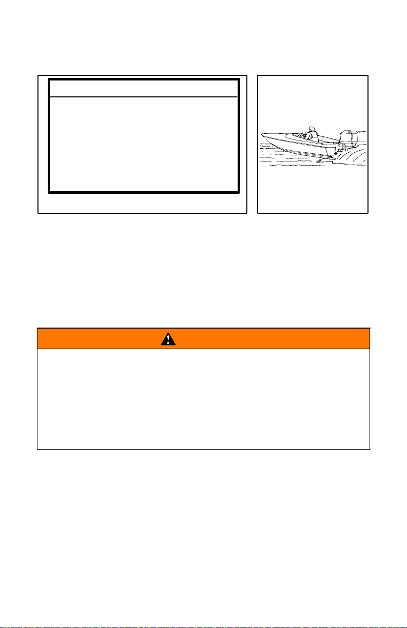
High-Speed And High-Performance Boat Operation
2 If you are not familiar with high-performance boat operation we
recommend that you first request an orientation/demonstration
ride with your dealer or an operator experienced with your boat/
outboard combination. Refer to the “Guide to Hi-Performance
Boat Operation” booklet (Part Number 90-849250) included in
your literature packet.
5
Page 8
ob
GENERAL INFORMATION
gob8
obg6
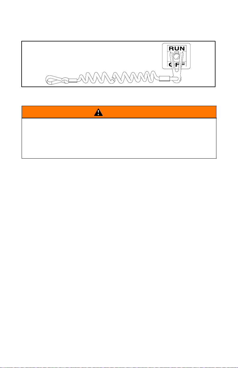
Lanyard Stop Switch
WARNING
Should the operator fall out of the boat, the possibility of serious injury or death from being run over by the boat can be
greatly reduced by stopping the engine immediately. Always
properly connect both ends of the stop switch lanyard – to the
stop switch and the operator.
1. The purpose of a lanyard stop switch is to turn off the engine
when the operator moves far enough away from the operator ’s
position (as in accidental ejection from the operator’s position)
to activate the switch. A lanyard stop switch can be installed as
an accessory – generally on the dashboard or side adjacent to
the operator’s position.
2. While activation of the lanyard stop switch will stop the engine
immediately, a boat will continue to coast for some distance depending upon the velocity and degree of any turn at shut-down.
However, the boat will not complete a full circle. While the boat
is coasting, it can cause injury to anyone in the boat’s path as
seriously as the boat would when under power.
6
Page 9

ob
GENERAL INFORMATION
Lanyard Stop Switch (Continued)
WARNING
Avoid serious injury or death from deceleration forces resulting from in accidental stop switch activation. The boat operator should never leave the operator’s station without first disconnecting the stop switch lanyard cord from themself.
Accidental or unintended activation of the Lanyard Stop Switch during normal operation is a possibility and could cause any, or all, of
the following potentially hazardous situations:
1. Occupants could be thrown forward due to unexpected loss of
forward motion – a particular concern for passengers in the front
of the boat who could be ejected over the bow and possibly
struck by the gear case or propeller.
2. Loss of power and directional control in heavy seas, strong current or high winds.
3. Loss of control when docking.
7
Page 10

ob
GENERAL INFORMATION
gob3
Protecting People In The Water
WHILE YOU ARE CRUISING
It is very difficult for a person in the water to take quick action to avoid
a boat heading in their direction even at slow speed.
Always slow down and exercise extreme caution any time you are
boating in an area where there might be people in the water.
Whenever a boat is moving (even coasting) even with the outboard
in neutral position, there is sufficient force by the water to rotate the
propeller. This neutral propeller rotation can cause serious injury.
WHILE BOAT IS STATIONARY
Shift outboard into neutral and shut off the engine before allowing
people to swim or be in the water near your boat.
WARNING
Stop your engine immediately whenever anyone in the water
is near your boat. Serious injury to the person in the water is
likely if contacted by a rotating propeller, a moving boat, a
moving gear case, or any solid device rigidly attached to a
moving boat or gear case.
8
Page 11

gob4
GENERAL INFORMATION
a
1
Courtesy of ABYC
Carbon Monoxide Risk
WARNING
Avoid the combination of a running engine and poor ventilation. Prolonged exposure to carbon monoxide in sufficient
concentration can lead to unconsciousness, brain damage,
or death.
Carbon monoxide is a deadly gas that is odorless, colorless and
tasteless and is present in the exhaust fumes of all internal combustion engines.
Early symptoms of carbon monoxide poisoning which should not be
confused with seasickness or intoxication, include headache, dizziness, drowsiness, and nausea.
SUFFICIENT FRESH AIR FLOW
1 Example of desired air flow through the boat;
a. Ventilate passenger area, open side curtains, or forward
hatches to remove carbon monoxide fumes.
9
Page 12
ob
gob39
2
GENERAL INFORMATION
ba
a
3
obi3
b
Courtesy of ABYC
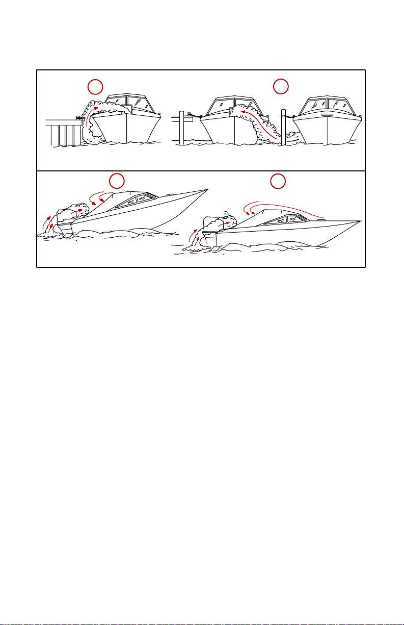
Carbon Monoxide Risk (Continued)
INSUFFICIENT FRESH AIR FLOW
Under certain conditions, enclosed or canvas enclosed cabins or
cockpits with insufficient ventilation may draw in carbon monoxide.
Install one or more carbon monoxide detectors in your boat.
Although rare, on a very calm day, swimmers and passengers in an
open stationary boat with a running engine, or near a running engine
may be exposed to a hazardous level of carbon monoxide.
Insufficient Air Flow Could Occur If:
2 While boat is stationary:
a. Boat moored in a confined space with the engine running.
b. Boat is moored close to another boat with its engine running.
3 While boat is moving:
a. Running the boat with the trim angle of the bow too high.
b. Running the boat with no forward hatches open (station
wagon effect).
10
Page 13
ob
GENERAL INFORMATION
gob4
obu1
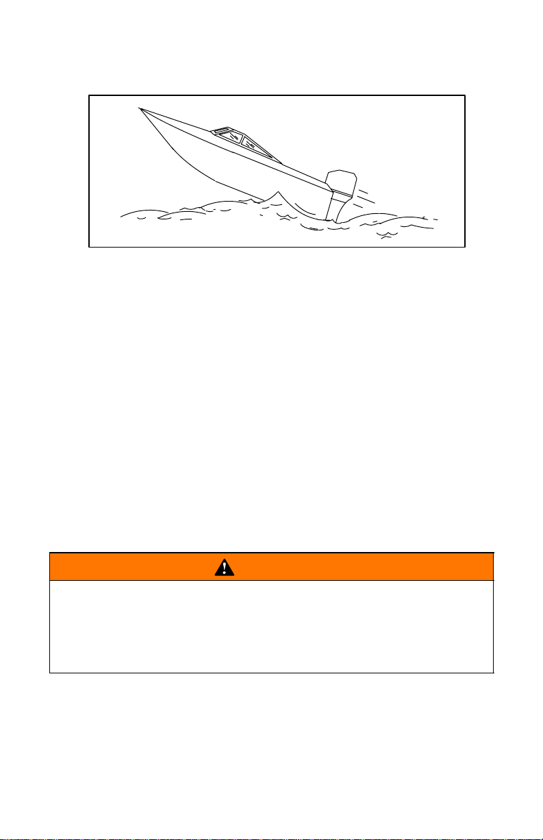
Wave And Wake Jumping
Operating recreational boats over waves and wakes is a natural part
of boating, However, when this activity is done with speed to force
the boat hull partially or completely out of the water, certain hazards
arise, particularly when the boat re-enters the water.
The primary concern is the boat changing direction while in the midst
of the jump. In such case the landing may cause the boat to violently
veer in a new direction. Such a sharp change in direction or turn can
cause occupants to be thrown out of their seats or out of the boat.
There is another less common hazardous result from allowing your
boat to launch off a wave or wake. If the bow of your boat pitches
down far enough while airborne, upon water contact it may penetrate under the water surface and “submarine” for an instant. This
will bring the boat nearly to a stop in an instant and can send the occupants flying forward. The boat may also steer sharply to one side.
WARNING
Avoid serious injury or death from being thrown within or out
of a boat when it lands after jumping a wave or wake. Avoid
wave or wake jumping whenever possible. Instruct all occupants that if a wake or wave jump occurs, get low and hang
on to any boat hand hold.
11
Page 14
ob
GENERAL INFORMATION
gob4
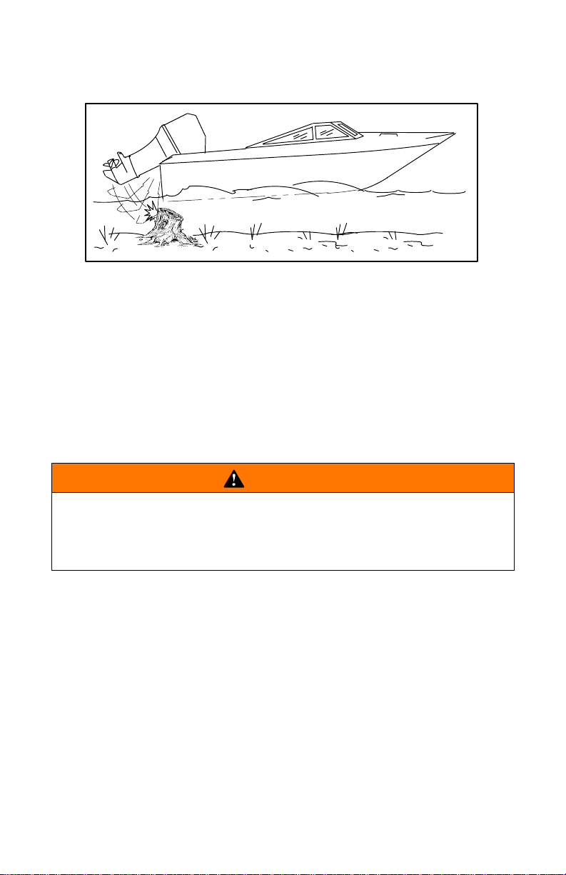
obt1
Impact With Underwater Hazards
Reduce speed and proceed with caution whenever you’re driving a
boat in shallow water areas or in areas where the waters are suspected of having underwater obstacles that could be struck by the
outboard or the boat bottom. The most important thing you can
do to help reduce injury or impact damage from striking a floating or underwater object is control the boat speed. Under these
conditions, boat speed should be kept to a minimum planing
speed (15 to 25 MPH).
WARNING
To avoid serious injury or death from all or part of an outboard
coming into the boat after striking a floating or underwater obstacle maintain a top speed no greater than minimum planing
speed.
Striking a floating or underwater object could result in an infinite
number of situations. Some of these situations could result in the following:
• Part of the outboard or the entire outboard could break loose and
fly into the boat.
• The boat could move suddenly in a new direction. Such a sharp
change in direction or turn can cause occupants to be thrown out
of their seats or out of the boat.
• A rapid reduction in speed. This will cause occupants to be
thrown forward, even out of the boat.
• Impact damage to the outboard and/or boat.
(continued on next page)
12
Page 15
GENERAL INFORMATION
obn2
Impact W ith Underwater Hazards (Continued)
Keep in mind, one of the most important things you can do to help
reduce injury or impact damage in these situations is control the
boat speed. Boat speed should be kept to a minimum planing speed
when driving in waters known to have underwater obstacles.
After striking a submerged object, stop the engine as soon as possible and inspect the outboard for any broken or loose parts. If damage is present or suspected, the outboard should be taken to an authorized dealer for a thorough inspection and necessary repair.
The boat should also be checked for any hull fractures, transom
fractures, water leaks.
Operating a damaged outboard could cause additional damage to
other parts of the outboard, or could affect control of the boat. If continued running is necessary, do so at greatly reduced speeds.
WARNING
Avoid serious injury or death from from loss of boat control.
Continued boating with major impact damage can result in
sudden outboard component failure with or without subsequent impacts, Have the outboard thoroughly inspected and
any necessary repairs made.
13
Page 16

GENERAL INFORMATION
obj1
Selecting Accessories For Your Outboard
Genuine Mercury Marine Accessories have been specifically designed and tested for your outboard.
Mercury Marine accessories are available from Mercury Marine
dealers.
Some accessories not manufactured or sold by Mercury Marine are
not designed to be safely used with your outboard or outboard operating system. Acquire and read the installation, operation, and
maintenance manuals for all your selected accessories.
WARNING
Check with your dealer before installing accessories. Misuse
of acceptable accessories or the use of unacceptable accessories can result in serious injury, death, or product failure.
Safe Boating Suggestions
In order to safely enjoy the waterways, familiarize yourself with local
and other governmental boating regulations and restrictions, and
consider the following suggestions.
Use Life Jackets. Have an approved life jacket of suitable size for
each person aboard and have it readily accessible (it is the law).
However we strongly recommend that everyone aboard wear their
life jacket.
Do not overload your boat. Most boats are rated and certified for
maximum load (weight) capacities (refer to your boat capacity
plate). If in doubt, contact your dealer or the boats manufacturer.
Perform safety checks and required maintenance. Follow a regular schedule and ensure that all repairs are properly made.
Know and obey all nautical rules and laws of the waterways.
Boat operators should complete a boating safety course. Courses
are offered in the U.S.A. by (1) The U.S. Coast Guard Auxiliary, (2)
The Power Squadron, (3) The Red Cross and (4) your state boating
law enforcement agency. Inquiries may be made to the Boating Hotline, 1-800-368-5647 or the Boat U.S. Foundation information number 1-800-336-BOAT.
(continued on next page)
14
Page 17

GENERAL INFORMATION
Safe Boating Suggestions (Continued)
Make sure everyone in the boat is properly seated. Don’t allow
anyone to sit or ride on any part of the boat that was not intended
for such use. This includes backs of seats, gunwales, transom, bow,
decks, raised fishing seats, any rotating fishing seat; anywhere that
sudden unexpected acceleration, sudden stopping, unexpected
loss of boat control or sudden boat movement could cause a person
to be thrown overboard or into the boat.
Never be under the influence of alcohol or drugs while boating
(it is the law). They impair your judgment and greatly reduce your
ability to react quickly.
Prepare other boat operators. Instruct at least one person on
board in the basics of starting and operating the outboard and boat
handling in case the driver becomes disabled or falls overboard.
Passenger boarding. Stop the engine whenever passengers are
boarding, unloading or are near the back (stern) of the boat. Just
shifting the outboard into neutral is not sufficient.
Be alert. The operator of the boat is responsible by law to “maintain
a proper lookout by sight (and hearing).” The operator must have an
unobstructed view particularly to the front. No passengers, load, or
fishing seats should block the operators view when operating the
boat above idle speed.
Never drive your boat directly behind a water skier in case the
skier falls. As an example, your boat traveling at 25 miles per hour
(40 km/hr) in 5 seconds will overtake a fallen skier who was 200 feet
(61m) in front of you.
Boat operators are required by law to file a Boating Accident
Report with their state boating law enforcement agency when their
boat is involved in certain boating accidents. A boating accident
must be reported if: 1. there is loss of life or probable loss of life, 2.
there is personal injury requiring medical treatment beyond first aid,
3. there is damage to boats or other property where the damage val-
ue exceeds $500.00 or 4. there is complete loss of the boat. Seek
further assistance from local law enforcement.
(continued on next page)
15
Page 18
obl2
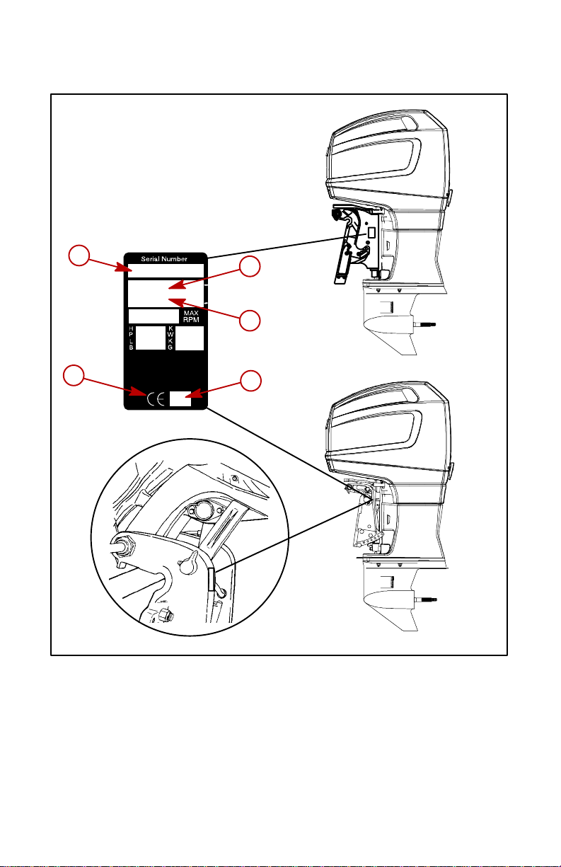
Recording Serial Number
a
OGXXXXXX
19XX
XXXX
b
c
e
XX
d
Record the following numbers from your engine as shown for future
reference.
a-Serial Number
b-Model Year
c-Model Designation
d-Year Manufactured
e-Certified Europe Insignia
16
Page 19

ob
GENERAL INFORMATION
Specifications
Models 300 - Pro Max 3.0L
Propshaft Horsepower 300
Propshaft Kilowatts 224
ECU Box Rev Limit 6200
Idle RPM (In or Out of Gear) 650 RPM
Weight
Piston Displacement 185 cu. in. (3044cc)
Bore 3.626 in. (92.1mm)
Stroke 3.00 in (76.2 mm)
Recommended Spark Plug Champion QL77CC (.035” Gap)
Firing Order 1-2-3-4-5-6
Idle Speed Pickup Timing Non Adjustable
Fuel Pressure 38-40 psi. (262-276 kPa)
Min. Water Pres.
@ 7500 -5500 RPM
Fleetmaster
Gear Ratio Torquemaster
Sportmaster
Recommended Gasoline Refer to Fuel Section
Recommended Oil Refer to Fuel Section
Recommended Gear Case
Oil
Gear Case Lubricant Cap. 27 fl. oz. (798 ml)
Mercury Precision Hi-Performance
Gear Lube (92-802854A1)
465 lbs.
(211 kg)
12 psi. Minimum
1.75:1
1.75:1
1.62:1 or 1.75:1
Battery Rating
Charging System Output 60 amps Max. (847Watts)
Minimum reserve capacity rating
of 100 minutes and CCA of 350
17
Page 20
GENERAL INFORMATION
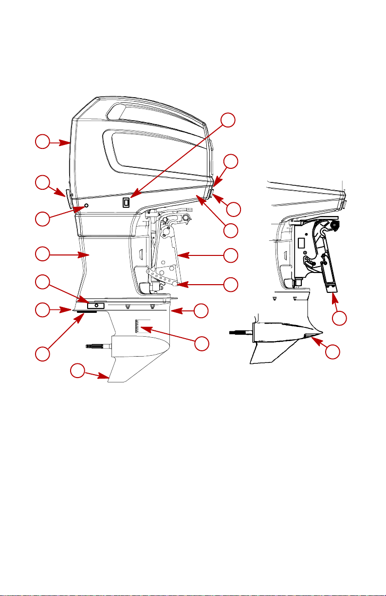
Component Identification
1
3
9
10
4
6
8
7
8
15
1. Top Cowl
2. Cowl Latch (Front)
3. Cowl Latch (Rear)
4. Water Pump Indicator Hose
(Tell-Tail)
5. Bottom Cowl
6. Drive Shaft Housing
7. Anti-Ventilation Plate
8. Corrosion Anode(s)
2
5
11
12
13
8
14
14
9. Cowl Mount Trim Switch
10. Wiring Harness, Fuel line and
Control Cables (Install thru bottom cowl)
11. Transom Brackets
12. Trim Adjustment Bolt
13. Gear Case
14. Cooling Water Intake Holes
15. Skeg
18
Page 21
GENERAL INFORMATION
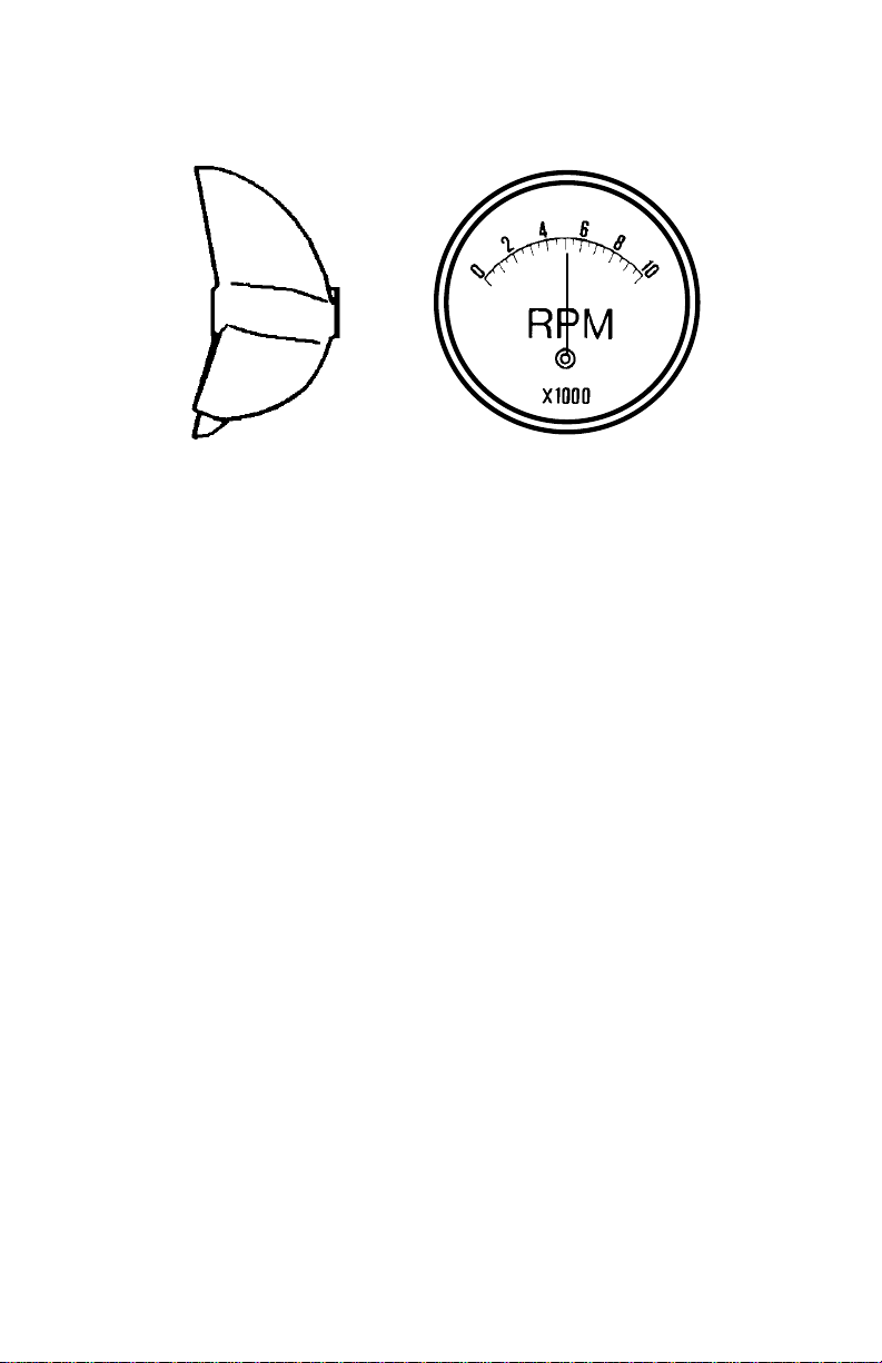
Propeller Selection
Select a propeller that allows the engine to operate in the upper half
of the recommended full throttle RPM range with the boat normally
loaded (refer to Specifications).
If changing conditions (such as warmer, more humid weather, operation at higher elevations, increased boat load, or a dirty boat bottom/gear case) cause the RPM to drop below the recommended
range a propeller change or boat cleaning may be required.
Check full-throttle RPM using an accurate tachometer with the engine trimmed out to a balanced-steering condition (steering effort
equal in both directions) without causing the propeller to “break
loose.”
19
Page 22
TRANSPORTING
1
2
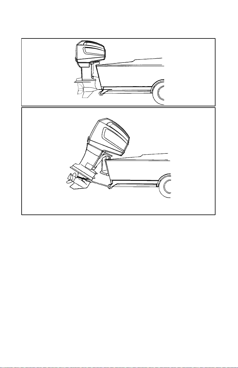
Trailering Boat/Outboard
1 Trailer your boat with the outboard tilted down when ever pos-
sible (vertical operating position).
2 If additional ground clearance is required for, railroad crossings,
driveways or trailer bouncing, support the outboard using a support device. Contact your local dealer for recommendations.
IMPORTANT: Do not rely on the power trim/tilt system or tilt
support lever to maintain proper ground clearance for trailering. The outboard tilt support lever is not intended to support
the outboard for trailering.
To prevent the propeller from spinning freely shift into forward gear.
20
Page 23

oe
FUEL & OIL
Gasoline Recommendations
USA AND CANADA
Use a major brand of automotive unleaded gasoline with a minimum
posted octane rating (R + M
contain fuel injector cleaner are recommended for added internal
engine cleanliness.
INTERNATIONAL
Use a major brand of automotive unleaded gasoline with a minimum
posted octane rating of 98RON. Automotive gasolines that contain
fuel injector cleaner are preferred for added internal engine cleanliness. Leaded gasoline is acceptable in areas where unleaded gasoline is not available. However, exhaust passageway corrosion may
occur due to the accumulation of exhausted lead particles.
GENERAL RECOMMENDATIONS
During periods of extended non use, a fuel stabilizer is highly recommended (See Storage Section).
Leaded Gasoline is acceptable to use in areas where unleaded is
not available. However, exhaust passageway corrosion may occur
due to the accumulation of exhausted lead particles.
ALCOHOL IN GASOLINE
÷ 2) of 92. Automotive gasolines that
We do not recommend gasoline containing alcohol due to the possible adverse effect the alcohol may have on the fuel system. If only
gasoline containing alcohol is available, it must not contain more
than 10% ethanol or 5% methanol, and the addition of a Mercury
Marine Water Separating Fuel Filter is recommended.
If gasoline containing alcohol is used or if you suspect the presence
of alcohol in your gasoline, increase your inspection of the fuel system, visually checking for fuel leaks or abnormalities.
Gasoline containing alcohol may cause the following problems to
your outboard and fuel system:
• Corrosion of metal parts.
• Deterioration of elastomers and plastic parts.
• Fuel penetrating through flexible fuel lines.
• Wear and damage of internal engine parts.
(continued on next page)
21
Page 24

oe
FUEL & OIL
ALCOHOL IN GASOLINE (CONTINUED)
• Starting and operating difficulties.
• Vapor lock or fuel starvation.
The tendency of gasoline containing alcohol to absorb moisture
from the air , results in a phase of water and alcohol which separates
from the gasoline in the fuel tank.
The adverse effects of alcohol are more severe with methanol and
are worse with increasing content of alcohol.
Oil Recommendation
Use Mercury Precision Premium Plus 2-Cycle TC-W3 Outboard Oil.
Emergency Use Only: If Mercury Precision Premium Plus 2-Cycle
TC-W3 Outboard Oil is not available, NMMA Certified 2-Cycle
TC-W3 Oil may be substituted.
Periodically consult with your dealer to get the latest gasoline and
oil recommendations. If Mercury Precision Premium 2-Cycle
TC-W3 Outboard Oil is not available, substitute a 2-Cycle outboard
manufacturers oil that is NMMA Certified TC-W3, or another brand
of 2-Cycle outboard oil that is NMMA Certified TC-W3. The use of
an inferior 2-Cycle outboard oil can reduce engine durability. Dam-
age from use of inferior oil may not be covered under the limited warranty.
22
Page 25

oe
FUEL & OIL
Filling Fuel Tank
WARNING
Avoid serious injury or death from a gasoline fire or explosion. Always stop the engine and DO NOT smoke or allow
open flames or sparks in the area while filling fuel tanks. To
help prevent a static charge during filling, portable fuel tanks
must be removed from the boat and placed directly on the
ground for filling.
1. Fill fuel tanks outdoors away from heat, sparks, and open
flames.
2. Remove portable fuel tanks from boat to refill them.
3. Always stop engine before refilling tanks.
4. Do not completely fill the fuel tanks. Leave approximately 10%
of the tank volume unfilled. Fuel will expand in volume as its temperature rises and can leak under pressure if the tank is completely filled.
23
Page 26

oe
FUEL & OIL
goe9
21
oeo1
Filling Remote Oil Tank
1
Remove filler cap and fill with the specified oil. Oil tank capacity
is 3 gallons (11.5 liters). Replace filler cap and tighten securely.
IMPORTANT: Always make sure the oil tank caps are threaded
on tight. An air leak will prevent oil flow to the engine.
NOTE: Prior to running the engine, mark the oil level in the remote
oil supply tank for later reference. At the end of the break-in period,
visually check to see if the oil level in the remote oil supply tank has
dropped. Oil usage indicates the oil injection system is functioning
correctly.
Filling Engine Mounted Oil Reservoir Tank
NOTE: Filling this tank is only necessary if the oil level should ever
drop and the low oil warning system is activated.
2 Remove top cowl. Loosen engine mounted oil reservoir tank fill-
er cap and fill the remote oil tank with the specified oil. Run engine until the oil reservoir tank is filled by the remote tank. Tighten the oil reservoir tank cap securely. Stop the engine and
replace the top cowl.
24
Page 27

og
FEATURES & CONTROLS
gog142
Side Mount Console
f
a
c
b
h
Panel
a
c
i
b
c
a
g
i
b
d
e
1
oge5
d
f
g
e
Remote Control Features
1
Your boat may be equipped with one of the Mercury Precision
remote controls shown. If not, consult your dealer for operation
of your remote control.
a-Control Shift/Throttle Handle
b-Neutral Release Lever
c-Trim/Tilt Switch
d-Lanyard Stop Switch – Read the Lanyard Stop Switch safety
explanation and Warning in the General Information Section.
e-Lanyard – Read the lanyard stop switch safety explanation
and warning in the General Information Section.
f-Throttle Friction Adjustment
g-Ignition Key Switch, Choke
h-Fast Idle Lever – Raising lever will increase engine idle
speed in neutral.
i-Throttle Only Button – Pushing the button in will enable ad-
vancing the control handle and increase engine idle speed
without shifting outboard into gear.
f
25
Page 28

FEATURES & CONTROLS
b
1
a
2
Warning Horn System
1
A warning horn may be located inside the remote control (a) or
under the dash (b) connected to the ignition key switch. The
warning horn sounds when one of the following outboard warning systems is activated.
• Low oil level in oil injection system (see explanation following).
• Engine over-speed protection system is activated (see explana-
tion following).
• An electrical sensor not functioning (see explanation following).
• Engine overheat (see explanation following).
• Water in fuel filter reaches full level (see explanation following).
2 When the ignition key is initially turned on, the warning horn will
sound for a moment as a test to tell you the system is working.
Failure of this test indicates a problem. Have the outboard
checked by your dealer.
NOTE: If you are in a stranded situation, stopping the engine and
allowing it to cool down will usually allow some additional low speed
(idle) running time before the engine starts to overheat again.
IMPORTANT: The overheat problem must be corrected before
you can resume normal operation.
(continued on next page)
26
Page 29

og
FEATURES & CONTROLS
Warning Horn System (Continued)
LOW OIL LEVEL
The low oil level warning is activated when the remaining oil in the
engine mounted oil reservoir tank drops below 50 fl. oz. (1.5 liters)
You still have an oil reserve remaining for 50 minutes of full speed
operation.
IMPORTANT: The engine mounted oil reservoir tank (located
beneath the top cowl) along with the remote oil tank will have
to be refilled (refer to Fuel & Oil Section).
The low oil level warning system works as follows:
3 The warning horn will begin a series of four beeps. If you contin-
ue to operate the outboard, the horn will beep every two minutes.The engine has to be shut off to reset the warning system.
CAUTION
To avoid engine damage caused by running out of oil, it is best
to refill the oil injection system as soon as the low oil warning
is activated.
27
(continued on next page)
Page 30

og
FEATURES & CONTROLS
a
b
5
Warning Horn System (Continued)
ENGINE OVERHEAT
The engine overheat warning is activated when the engine temperature is too hot.
The engine overheat warning system works as follows:
4 The warning horn sounds continuously. The warning system will
automatically limit the engine speed to 3000 RPM.
5 If the engine overheats, immediately reduce throttle speed to
idle. Shift outboard into neutral and check for a steady stream
of water coming out of the water pump indicator hole (a).
CAUTION
Operating the engine while overheated will cause engine
damage. The overheat problem must be corrected before you
can resume normal operation.
a. If no water is coming out of the water pump indicator
hole (a) or flow is intermittent:
• Stop engine and check cooling water intake holes for obstruction.
• If no obstruction is found, this may indicate a blockage in the cool-
ing system or a water pump problem.
• Have the outboard checked by your dealer.
b. If a steady stream of water is coming out of the water
pump indicator hole (a) and warning horn continues:
• There may be insufficient cooling water or an engine problem.
• Stop engine and have it checked by your dealer.
(continued on next page)
28
Page 31

og
FEATURES & CONTROLS
ogb18
Warning System (Continued)
ENGINE OVER-SPEED PROTECTION SYSTEM
The engine over-speed protection system is activated when the engine speed exceeds the maximum allowable RPM.
The engine over-speed protection system works as follows:
6 Anytime the engine over-speed system is activated, the warning
horn begins beeping. In addition, the system will automatically
reduce the engine speed to within the allowable limit by retarding the ignition timing.
NOTE: Your engine speed should never reach the maximum limit
to activate the system unless the propeller is ventilating, an incorrect
propeller is being used, or the propeller is faulty. If engine overspeed continues, have the outboard checked by your dealer.
ELECTRICAL SENSOR NOT FUNCTIONING
The warning system is activated if an electrical engine sensor is not
functioning, or is out of its operating range.
The warning system works as follows:
7 The warning horn begins beeping. Have the outboard checked
by your dealer.
WATER SEPARATING FUEL FILTER IS FULL OF WATER ON
ENGINES WITH ELECTRONIC FUEL INJECTION (EFI)
The water level detection warning is activated when water in the
water separating fuel filter reaches the full level. The water can be
removed from the filter. Refer to Maintenance Section for filter
removal.
8 The warning horn will begin a series of four beeps. If you contin-
ue to operate the outboard, the horn will beep every two minutes.
29
Page 32

og
FEATURES & CONTROLS
gog70
a
b
Power Trim And Tilt
Outboard position can be adjusted by pressing trim switch (a).
This range is used while operating your boat on plane.
• Pressing (DN): Moves the outboard in closer to the boat tran-
som, called trimming “in” or “down.”
• Pressing (UP): Moves the outboard further away from the boat
transom, called trimming “out” or “up.”
The term “trim”:
• Generally refers to the adjustment of the outboard within the first
° range of travel (b).
20
The term “tilt”:
• Generally refers to adjusting the outboard further up out of the
water.
With the engine turned off, the outboard can be tilted out of the water. At low idle speed, the outboard can also be tilted up past the trim
range to permit, for example, shallow water operation.
(continued on next page)
30
Page 33

FEATURES & CONTROLS
osf1
Power Trim Operation
With most boats, operating around the middle of the “trim” range will
give satisfactory results. Trimming your outboard all the way in or out
may improve performance but cause some potential control hazards.
WARNING
Avoid possible serious injury or death. When the outboard is
trimmed in or out beyond a neutral steering condition, a pull
on the steering wheel in either direction may result. Failure to
keep a continuous firm grip on the steering wheel when this
condition exists can result in loss of boat control as the outboard can turn freely. The boat can now “spin out” or go into
a very tight maximum turn which, if unexpected, can result in
occupants being thrown within the boat or out of the boat.
Consider the following lists carefully.
Trimming In or Down Can:
• Lower the bow of the boat.
• Result in quicker planing off.
• Generally improve the ride in choppy water.
• Increase steering torque or pull to the right (with the normal right
hand rotation propeller).
• In excess, lower the bow to a point at which the boat begins to
plow with the bow in the water while on plane. This can result in
an unexpected turn in either direction called “bow steering” or
“over steering” if any turn is attempted, or if a significant wave is
encountered.
(continued on next page)
31
Page 34

FEATURES & CONTROLS
a
1
Power Trim Operation (continued)
WARNING
Avoid possible serious injury or death. Adjust outboard to an
intermediate trim position as soon as boat is on plane to avoid
possible ejection due to boat spin-out. Do not attempt to turn
boat when on plane if outboard is trimmed extremely in or
down and there is a pull on the steering wheel.
1 The trim in limit may be set by inserting the tilt pin (a) into the de-
sired transom bracket hole.
Trimming Out or Up can:
• Lift the bow higher out of the water.
• Generally increase top speed.
• Gain clearance over submerged objects or a shallow bottom.
• Increase steering torque or pull to the left at a normal installation
height (with the normal right hand rotation propeller).
• In excess, cause boat “porpoising” (bouncing) or propeller venti-
lation.
• Cause engine overheating if any cooling water intake holes are
above the water line.
32
Page 35

og
FEATURES & CONTROLS
gog62
c
a
b
1-3 4
Tilting Operation (Fleet Master & Torque Master Gear Cases)
To tilt outboard, shut off the engine and press the trim/tilt switch or
auxiliary tilt switch to the up position. The outboard will tilt up until
the switch is released or it reaches its maximum tilt position.
1 Engage the tilt support lever (a), by pushing in and rotating knob
(b) to bring support lever upward.
2 Lower outboard to rest on the tilt support lever.
3 Disengage the tilt support lever, by raising the outboard off the
support lever and rotating the lever down. Lower the outboard.
osc1
Auxiliary Tilt Switch
4
This switch (c) can be used to tilt the outboard up or down using
the power trim system.
(continued on next page)
33
Page 36

FEATURES & CONTROLS
1
2–3
c
4
Tilting Operation (Sport Master Gear Case)
To tilt outboard, shut off the engine and press the trim/tilt switch to
the up position. The outboard will tilt up until the switch is released
or it reaches its maximum tilt position.
1 Push in on the tilt support release knob.
2 Move tilt support lever into locking position and lower outboard
to rest on the tilt support lever.
3 Disengage the tilt support lever by raising the outboard off the
support lever and rotating the lever up until it locks. Lower the
outboard.
osc1
Auxiliary Tilt Switch
This switch (c) can be used to tilt the outboard up or down using
4
the power trim system.
34
Page 37

og
FEATURES & CONTROLS
og71
1
Manual Tilting (Fleet Master & Torque Master Models Only)
If the outboard cannot be tilted using the power trim/tilt switch, the
outboard can be manually tilted.
1 Turn out the manual tilt release valve 3 turns (counterclockwise).
This allows manual tilting of the outboard. Tilt the outboard to the
desired position and tighten the manual tilt release valve.
NOTE: The manual tilt release valve must be tightened before operating the outboard to prevent the outboard from tilting up during
reverse operation.
35
Page 38

og
FEATURES & CONTROLS
1
2
Manual Tilting (Sportmaster Models)
If the outboard cannot be tilted using the power trim/tilt switch, the
outboard can be manually tilted by the following procedures.
CAUTION
The engine must be supported during lowering in the following steps or the engine may drop rapidly and personal injury
as well as damage to the engine could occur.
NOTE: Place a suitable container below the connection and wrap
the connection with a cloth to collect any fluid which may be dispelled during the following operations.
1 TILTING (DOWN / IN):
• Loosen the (starboard-right, facing engine from front) hydraulic
connection at the front of the swivel bracket.
• Slowly lower the engine to the desired position, and reconnect
the hydraulic connection.
2 TILTING (UP /OUT):
• Loosen the (port-left, facing engine from front) hydraulic connec-
tion at the front of the swivel bracket.
• Slowly lift the engine and engage the tilt lock lever . Reconnect the
hydraulic connection.
IMPORTANT: If the hydraulic lines are disconnected and fluid
is lost, the power trim pump must be refilled and the lines
purged of air.
36
Page 39

of
OPERATION
Engine Break-in
CAUTION
Severe damage to the engine can result by not complying
with the Engine Break-in Procedure.
BREAK-IN PROCEDURE
For the first 30 gals. (114 L) of fuel mixture, mix oil in the fuel
tank at 25:1 (4%). This is in addition to the oil supplied to the
engine by the oil injection system. (See following chart)
Always vary throttle settings during Break-in
1st HOUR
• Allow engine to warm-up for 30 - 60 seconds.
• Do not idle for more than 10 minutes
• Run the engine the majority of time between 3000 - 4500 RPM
(approximately three quarter throttle).
• Short bursts of full throttle for periods up to 10 seconds are
acceptable.
• Vary engine speed. Change engine speed approximately
every two (2) minutes.
• Avoid trimming the outboard out (up) beyond a vertical trim
position during operation.
• Avoid using hydraulic jack plate (if equipped) to raise engine
during break-in cycle.
NEXT 3 HOURS: Change engine speed every 10 minutes.
CAUTION
It is the boat operators responsibility to always drive in a safe
manner. Improper trim angle of the outboard when driving at
speed can be difficult and dangerous. Trim angle is specified
to help guide the operator in determining how to put the
proper load on the engine during the break-in period. These
guidelines do not suggest or require unsafe boat operation.
37
Page 40

of
OPERATION
Engine Break-in (con’t)
oeh2
GASOLINE/OIL MIXTURE (FIRST 30 GALS [114L] OF FUEL)
Gas/Oil
Ratio
25:1 (4 %) 5 fl. oz
GASOLINE RECOMMENDATION
Use a major brand of automotive unleaded gasoline with a minimum
posted octane rating (R + M
OIL RECOMMENDATION
Use Mercury Precision Premium Plus 2-Cycle TC-W3 Outboard Oil.
1 US Gal.
Gas
(3.8 L)
(148 ml)
Oil
3 Gallons
Gas
(11.5 L)
15 fl. oz.
(444 ml)
Oil
÷ 2) of 92.
6 Gallons
Gas
(23 L)
31 fl. oz.
(917 ml)
Oil
30 US Gal.
Gas
(114 L)
4.75 US qt
(4.5 L)
Oil
38
Page 41

of
OPERATION
Pre-Starting Check List
j Operator knows safe navigation, boating/operating procedures.
j An approved personal flotation device of suitable size for each
person aboard and readily accessible (it is the law).
j A ring type life buoy or buoyant cushion designed to be thrown
to a person in the water.
j Know your boats maximum load capacity. Look at the boat ca-
pacity plate.
j Arrange passengers and load in the boat so the weight is distrib-
uted evenly and everyone is seated in a proper seat.
j Tell someone where you are going and when you expect to
return.
j It is illegal to operate a boat while under the influence of alcohol
or drugs.
j Know the waters and area you will be boating; tides, currents,
sand bars, rocks, and other hazards.
j Engine lowered to run position with all water intake holes sub-
merged.
j Fuel tank vent cap open or fuel petcock “On”.
j Fuel supply OK.
j Oil supply (oil injection) OK.
j Lanyard stop switch in “Run” position and cord connected.
j Remote control in “Neutral”.
j Top cowl latches secure.
j Make inspection checks listed in the Inspection and Maintenance
Schedule. Refer to Maintenance Section.
39
Page 42

of
OPERATION
onf2
Operating In Freezing Temperatures
When using your outboard or having your outboard moored in freezing or near freezing temperature, keep the outboard tilted down at
all times so the gear case is submerged. This prevents trapped water in gear case from freezing and causing possible damage to the
water pump and other components.
If there is a chance of ice forming on the water, the outboard should
be removed and drained completely of water. If ice should form at
the water level inside the outboard drive shaft housing, it will block
water flow to the engine causing possible damage.
one1
Operating In Salt Water Or Polluted Water
We recommend flushing the internal water passages of your outboard with fresh water after each use in salt or polluted water to prevent a buildup of deposits from clogging the water passages. Refer
to “Flushing The Cooling System” procedure in the Maintenance
Section.
If you keep your boat moored in the water, always tilt the outboard
so the gear case is completely out of water (except in freezing temperature) when not in use.
Wash down the outboard exterior and flush out the exhaust outlet
of the propeller and gear case with fresh water after each use. Each
month, spray Mercury Precision Corrosion Guard (92-802878-55)
on external metal surfaces (do not spray on corrosion control
anodes as this will reduce the effectiveness of the anodes).
Operating At High Elevations
Your engine automatically compensates for high elevation changes.
A different pitch propeller may help reduce some normal performance loss resulting from reduced oxygen in the air. Consult your
dealer.
40
Page 43

of
OPERATION
b
a
1
onn2
2
Setting Trim Angle While Running Engine at Idle Speed
1
Submerging the exhaust relief hole (a) on the outboard can happen on some boats if you trim “full-in” while running at idle speed,
resulting in, exhaust restriction, rough idle, excessive smoke,
and fouled spark plugs. If this condition exists, trim outboard up
until exhaust relief hole is out of the water (b).
onk2
Operating in Shallow Water
2 When operating in shallow water, you can tilt the outboard be-
yond the maximum trim range to prevent hitting bottom.
a. Operate the engine at slow speed only. Do Not exceed 1200
RPM with the outboard trimmed beyond the side supports of
the swivel bracket.
b. Tilt outboard up. Make sure all the cooling water intake holes
stay submerged at all times.
41
Page 44

of
OPERATION
12
3
N
4
5
Starting The Engine
Before starting, read the Pre-Starting Check List, Special Operating
Instructions, in the Operation Section.
CAUTION
Never start or run your outboard (even momentarily) without
water circulating through all the cooling water intake holes in
the gear case to prevent damage to the water pump (running
dry) or overheating of the engine.
1 Lower the outboard to the run position. Make sure all the cooling
water intake holes are submerged.
2 Open fuel tank filler cap vent screw (manual venting fuel tanks).
3 Squeeze the fuel line primer bulb several times until it feels firm.
4 Set the lanyard stop switch to RUN position. Read the Lanyard
Stop Switch safety explanation and Warning in the General Information Section.
5 Shift outboard to neutral (N) position.
(continued on next page)
42
Page 45

of
gof82
OPERATION
6
ofe16
7
Starting The Engine (Continued)
NOTE: It is not necessary to use the neutral fast idle speed feature
on the remote control to increase engine speed for starting and
warm up. The electronic starting system will automatically increase
idle speed for starting and will reduce it as the engine warms up.The
engine does not require you to actuate the primer (choke) for starting. The electronic starting system will automatically prime the engine.
6 Turn the ignition key to START position. Release the key when
engine starts. If engine fails to start in 10 seconds, return the key
to ON position, wait 30 seconds and try again.
NOTE: Starting Flooded Engine – Advance the neutral high idle
speed feature on the remote control to the full high speed position.
Crank engine for 10 seconds, wait 30 seconds and repeat until engine starts.
7 Check for a steady stream of water flowing out of the water pump
indicator hole (allow approximately 10-15 seconds for the water
flow to start).
IMPORTANT: If no water is coming out of the water pump indicator hole, stop engine and check cooling water intake holes
for obstruction. No obstruction may indicate a water pump failure or blockage in the cooling system. These conditions will
cause the engine to overheat. Have the outboard checked by
your dealer. Operating the engine while overheated will cause
engine damage.
43
(continued on next page)
Page 46

of
OPERATION
gof78
F
ofe15
Starting The Engine (Continued)
Gear Shifting
IMPORTANT: Observe the following:
• Never shift outboard into gear unless engine is at idle.
• Never shift outboard into Reverse without the engine run-
ning.
1 Your outboard has three gear shift positions to provide opera-
tion. Forward (F), Neutral (out of gear) and Reverse (R).
N
R
41-3
2 When shifting, always stop at neutral position and allow the en-
gine speed to return to idle.
3 Always shift outboard into gear with a quick motion. Stopping The Engine
4
Reduce engine speed and shift outboard to neutral position.
Turn ignition key to OFF position.
44
Page 47

of
OPERATION
gof84
a
123
ofp14
Emergency Starting
If the starter system fails, use a spare starter rope (not provided) and
follow procedure.
IMPORTANT: Electronic Fuel Injected (EFI) models – If the battery voltage drops below 8 volts, the electric fuel pump will not
operate. With this low battery voltage condition, the engine
cannot be manually started.
1 Remove flywheel cover (a). Refer to Maintenance Section.
2 Shift outboard to neutral (N) position.
N
WARNING
When using emergency starter rope to start engine, the startin-gear protection provided by the remote control is inoperative. Make sure to set the outboard gear shift into neutral to
prevent outboard from starting in gear. Sudden unexpected
acceleration could result in serious injury or death.
3 Turn the ignition key to ON position.
(continued on next page)
45
Page 48

of
OPERATION
4 6
Emergency Starting (Continued)
WARNING
To prevent getting an electrical shock, DO NOT touch any ignition component, wiring or spark plug wire when starting or
running the engine.
WARNING
The exposed moving flywheel can cause serious injury. Keep
your hands, hair , clothing, tools, and other objects away from
engine when starting or running the engine. Do not attempt to
reinstall the flywheel cover or top cowl when engine is running.
4 Place the rope knot into the flywheel notch and wind the rope
clockwise around the flywheel under the alternator belt.
5 Pull the starter rope to start the engine.
6 After engine has started, do not reinstall the flywheel cover or
top cowl until the engine has been stopped.
46
Page 49

oh
MAINTENANCE
Outboard Care
To ensure safety and retain dependability keep your outboard in the
best operating condition by performing the periodic inspections and
maintenance listed in the Inspection and Maintenance Schedule.
Record maintenance performed in Maintenance Log at the back of
this book. Save all maintenance work orders and receipts.
ohr1
WARNING
Neglected outboard inspection and maintenance or performing maintenance or repairs you are not familiar with, could result in personal injury, death or product failure.
Submerged Outboard
A submerged outboard will require service within a few hours by an
authorized dealer once the outboard is recovered. This immediate
attention is necessary once the engine is exposed to the atmosphere to minimize internal corrosion damage to the engine.
Selecting Replacement Parts For Your Outboard
We recommend using original Mercury Precision replacement parts
and Lubricants.
WARNING
Using a replacement part that is inferior to the original part
could result in personal injury, death, or product failure.
oti1
EP A Emissions Regulations
All new outboards manufactured by Mercury Marine are certified to
the United States Environmental Protection Agency as conforming
to the requirements of the regulations for the control of air pollution
from new outboard motors. This certification is contingent on certain
adjustments being set to factory standards. For this reason, the factory procedure for servicing the product must be strictly followed
and, wherever practicable, returned to the original intent of the design. Maintenance, replacement, or repair of the emission con-
trol devices and systems may be performed by any marine SI
engine repair establishment or individual.
47
Page 50

oh
MAINTENANCE
Inspection And Maintenance Schedule
BEFORE EACH USE
1. Check that lanyard stop switch stops the engine.
2. Visually inspect the fuel system for deterioration or leaks.
3. Check outboard for tightness on transom.
4. Check steering system for binding or loose components.
5. Visually check steering link rod fasteners for proper tightness.
6. Check propeller blades for damage.
AFTER EACH USE
1. Flush out the outboard cooling system if operating in salt or polluted water.
2. If operating in salt water, wash off salt deposits and flush propeller and gear case exhaust outlet with fresh water.
EVERY 50 HOURS OF USE
1. Lubricate all lubrication points. (More frequently in salt water).
2. Inspect and clean/replace spark plugs.
3. Check corrosion control anodes. (More frequently in salt water).
4. Check fuel pressure.*
5. Drain and replace gear case lubricant.
6. Inspect battery.
∗ These items should be serviced by an authorized dealer.
(continued on next page)
48
Page 51

oh
MAINTENANCE
Inspection And Maintenance Schedule
(Continued)
EVERY 50 HOURS OF USE (CONT.)
7. Check engine timing setup.
8. Check control cable adjustments. ∗
9. Check alternator belt tension.
10. Check tightness of bolts, nuts, and other fasteners.
EVERY 100 HOURS OF USE OR ONCE YEARLY, WHICHEVER
OCCURS FIRST
1. Check power trim fluid.
2. Replace Water separating fuel filter.
3. Lubricate splines on the drive shaft and prop shaft. (If used in
salt water, more frequent service may be needed.)
4. Torque Master and Sport Master Gearcases – Lubricate entire
length of driveshaft with Mercury Precision anti-corrosion
grease. (92-802867A1) (If used in salt water, more frequent service may be needed.)*
5. Inspect fiberglass reeds for chipping or cracks.*
6. Use Mercury Precision QuicKleen (92-802877A1) in fuel.
EVERY 300 HOURS OR USE OR THREE YEARS
∗
∗
1. Replace water pump impeller (more often if: overheating occurs,
used in salt water, or reduced water pressure is noted).
2. Replace cylinder head O-ring seals.∗
BEFORE PERIODS OF STORAGE
1. Refer to Storage procedure.
∗
∗ These items should be serviced by an authorized dealer.
49
Page 52

MAINTENANCE
c
b
a
1-6
Flushing the Cooling System - Using Cowl Flushing Attachment
NOTE: Let engine cool to ambient temperature before flushing
system.
Flush the internal water passages of the outboard with fresh water
after each use in salt, polluted or muddy water. This will help prevent
a buildup of deposits from clogging the internal water passages.
NOTE: Engine should not be running when flushing the cooling
system. Do not flush engine using a water system that exceeds
45 psi.
1 Remove plug (a) from valve body (b) in the bottom cowl (port
side).
2 Attach coupling assembly (22-852400) (c) to the valve body (b).
located in the bottom cowl (port side).
3 Attach a water hose to the coupling assembly (c).
4 Turn water supply on and flush engine for 3 to 5 minutes. Verify
water dump from tell-tale hose.
5 Turn off the water, and remove the flushing attachment.
6 Insert plug (a) into valve body (b) (tighten securely).
50
Page 53

MAINTENANCE
1-4 5
Flushing the Cooling System (Continued) - Using
Gear Case Flushing Attachments
WARNING
To avoid possible injury when flushing, remove the propeller.
Refer to Propeller Replacement.
1 Remove propeller (refer to Propeller Replacement). Install the
flushing attachment to fit tightly over the cooling water intake.
2 Attach a water hose to the flushing attachment. Turn on the
water and adjust the flow so water is leaking around the flushing
attachment to ensure the engine receives an adequate supply
of cooling water.
3 Start the engine and run it at idle speed in neutral shift position.
4 Adjust water flow so excess water continues leaking out from
around the flushing attachment to ensure the engine is receiving
an adequate supply of cooling water.
5 Check for a steady stream of water flowing out of the water pump
indicator hoses. Continue flushing the outboard for 3 to 5 minutes, carefully monitoring water supply at all times.
6 Stop the engine, turn off the water, and remove the flushing at-
tachment. Reinstall the propeller.
51
Page 54

oh
MAINTENANCE
c
a
b
1
e
f
2
d
Top Cowl Removal and Installation
WARNING
Avoid Serious Injury or Death. Do Not attempt to remove or
install cowl while engine is running.
1 Removal
a-Rotate rear latching handle clockwise.
b-Pull out on front latching handle and at the same time lift
front of cowl.
c-Lift cowl from engine.
2 Installation
d-Lower top cowl into position over engine.
e-Rotate the rear latch counterclockwise to secure the rear
cowl latch.
f-Pull out on front latching handle and push down on the front
of the cowl to engage the front latch.
52
Page 55

oh
MAINTENANCE
12
Flywheel Cover Removal and Installation
REMOVAL
1 Remove flywheel cover by lifting off.
INSTALLATION
2 Install the flywheel cover two front pins into the front mounting
holes and push the bottom mounting holes onto the rear pins.
Fuel System
WARNING
Avoid serious injury or death from gasoline fire or explosion.
Carefully follow all fuel system service instructions. Always
stop the engine and DO NOT smoke or allow open flames or
sparks in the area while servicing any part of the fuel system.
Before servicing any part of the fuel system:
• Stop engine and disconnect the battery.
• Drain the fuel system completely.
• Fuel system service must be performed in a well ventilated area.
• Inspect any completed service work for sign of fuel leakage.
IMPORTANT: Use an approved container to collect and store
fuel. Wipe up any spillage immediately. Material used to contain
spillage must be disposed of in an approved receptacle.
FUEL LINE INSPECTION
Visually inspect the fuel line for cracks, swelling, leaks, hardness, or
other signs of deterioration or damage. If any of these conditions are
found, the fuel line must be replaced.
(continued on next page)
53
Page 56

h
MAINTENANCE
goh120
a
1
Fuel System (Continued)
WATER SEPARATING FUEL FILTER
NOTE: The warning system will turn on when water in the fuel filter
reaches the full level. Refer to “Warning System” in Features & Controls Section.
1 This filter removes moisture and also debris from the fuel. If the
filter becomes filled with water, the water can be removed. If the
filter becomes plugged with debris, the filter must be replaced
with a new filter.
Remove and replace filter as follows:
• Turn ignition key switch to OFF position.
• Disconnect wire (a) at bottom of filter. Remove filter by turning the
filter in the direction of the arrow (clockwise). Tip the filter to drain
fluid in a suitable container.
• Lubricate the sealing ring on the filter with oil. Thread on the filter
and tighten securely by hand. Reconnect the wire to the filter.
IMPORTANT: Visually inspect for fuel leakage from the filter by
squeezing the primer bulb until firm, forcing fuel into the filter.
54
Page 57

MAINTENANCE
a
d
b
c
ohi1
Steering Link Rod Fasteners
DUAL CABLE STEERING
Installation instructions for dual cable single engine applications are
included with the dual cable kit.
IMPORTANT: The steering link rod that connects the steering
cables to the engine must be fastened using special washer
head bolt (“a” – Part Number 10-849838) and self locking nylon
insert locknuts (“b” & “c” – Part Number 1 1-34863). These locknuts must never be replaced with common nuts (non locking)
as they will work loose/vibrate off freeing link rod to disengage.
WARNING
Disengagement of a steering link rod can result in the boat
taking a full, sudden, sharp turn. This potentially violent action can cause occupants to be thrown overboard exposing
them to serious injury or death.
Assemble steering link rod to steering cable with two flat washers (d)
and self locking nylon insert locknut (“b” – Part Number 11-34863).
Tighten locknut (b) until it seats, then back nut off 1/4 turn.
Assemble steering link rod to engine with special washer head bolt
(“a” – Part Number 10-849838) and self locking nylon insert locknut
(“c” – Part Number 11-34863). First torque bolt (a) to 20 lb. ft. (27.1
N·m), then torque locknut (c) to 20 lb. ft. (27.1 N·m).
55
Page 58

goh121
MAINTENANCE
a
b
c
1
omh1
2
Fuse Replacement
IMPORTANT: Always carry spare SFE 20 AMP fuses.
1 The electric starting circuit is protected from overload by an SFE
20 AMP fuse. If the fuse is blown, the electric starter motor will
not operate. Try to locate and correct the cause of the overload.
If the cause is not found, the fuse may blow again. Replace the
fuse with a fuse of the same rating.
Replace with a new SFE 20 AMP fuse.
ohk12
Corrosion Control Anodes
IMPORTANT: Anodes help protect the metal of the outboard
from galvanic corrosion by sacrificing their metal to be slowly
eroded instead of the outboard metals being eroded. All
anodes require periodic inspection, especially in salt water.
Replace any anodes before they are completely eroded. Never
paint or apply protective coating on the anode as effectiveness
of the anode will be reduced.
2 Your outboard has the following (four) corrosion control
anodes.
a-Two bars, one in each side of the gear case housing above
the anti-ventilation plate.
b-One plate installed under the anti-ventilation plate.
c-One bar across the bottom of the transom bracket assembly.
56
Page 59

oh
MAINTENANCE
goh112
N
12
Propeller Replacement
WARNING
4-53
If the propeller is rotated while the engine is in gear, there is
the possibility that the engine will crank over and start. To prevent this accidental engine starting and possible serious injury caused from being struck by a rotating propeller, always
shift outboard to neutral position and remove spark plug
leads before you service the propeller.
1 Shift outboard to neutral (N) position.
2 Remove spark plug leads to prevent engine from starting.
3 Straighten the bent tabs on the propeller nut retainer.
4 Place a block of wood between gear case and propeller to hold
propeller and remove propeller nut.
5 If propeller is seized to the shaft and cannot be removed, consult
an authorized dealer.
(continued on next page)
57
Page 60

oh
MAINTENANCE
a
67
f
e
b
c
e
d
f
8
d
c
a
b
9-10
Propeller Rep l a c e m e n t ( C o n t i n u e d )
Coat the propeller shaft with Mercury Precision Anti-Corrosion
6
Grease or 2-4-C Marine Lubricant with Teflon.
IMPORTANT: To prevent the propeller hub from corroding and
seizing to the propeller shaft, especially in salt water, always
apply a coat of the recommended lubricant to the entire propeller shaft at the recommended maintenance intervals and also
each time the propeller is removed.
7 Rubber Hub Propellers - Install thrust washer (a), propeller (b),
continuity washer (c), splined washer (d), propeller nut retainer
(e), and propeller nut (f) onto the shaft.
8 Replaceable Hub Propellers (Using Flo-Torq II Hub Assembly
Kit P/N 835258A1 or 835258A2) - Install forward thrust hub (a),
replaceable drive sleeve (b), propeller (c), drive sleeve adaptor
(d), propeller nut retainer (e) and propeller nut (f) onto the shaft.
9 Place a block of wood between gear case and propeller and
torque propeller nut to 55 lb. ft. (75 N·m).
10Secure propeller nut by bending three of the tabs into the thrust
hub grooves.
58
Page 61

oh
goh63
MAINTENANCE
12
ohm4
3
Spark Plug Inspection
Inspect spark plugs at the recommended intervals.
1 Remove the spark plug leads by twisting the rubber boots slight-
ly and pull off. Inspect spark plug boots and replace if cracked.
2 Remove the spark plugs to inspect and clean. Replace spark
plug if electrode is worn or the insulator is rough, cracked, broken, blistered, or fouled.
3 Set the spark plug gap. See Specification Chart in General In-
formation Section.
4 Before reinstalling spark plugs, clean away dirt on the spark plug
seats. Install plugs finger tight, and tighten 1/4 turn or torque to
20 lb. ft. (27 N·m).
Battery Inspection
The battery should be periodically inspected.
IMPORTANT: Read the safety and maintenance instructions
which accompany your battery.
1. Turn off the engine before servicing the battery.
2. Add water as necessary to keep the battery full.
3. Make sure the battery is secure.
4. Battery cable terminals should be clean, tight, and positive to
positive and negative to negative.
5. Make sure the battery is equipped with nonconductive terminal
shields to prevent accidental shorting of battery terminals.
59
Page 62

oh
MAINTENANCE
goh123
2
1
omk1
Alternator Drive Belt Tension Adjustment
The drive belt should be periodically inspected for condition and tension.
1 Check belt tension by pressing in on the belt at the point shown.
Proper tension allows the belt to be pressed in 1/2 in. (12.7mm).
2 If adjustment is required, loosen bolts and adjust belt. Re-torque
adjustment bolts to 40 lb. ft. (55 N·m).
60
Page 63

oh
goh124
MAINTENANCE
a
b
1
oho41
2
Lubrication Points
a-Mercury Precision Anti-Corrosion Grease (92-802867A1)
b-Mercury Precision 2-4-C w/Teflon (92-802859A1) or Mercury
Precision Special Lubricant 101 (92-802865A1)
1 (Fleet Master and Torque Master Models Only.) Trim Rod
Ball Ends – Turn the ball ends to work the lubricant into the ball
sockets.
2 Propeller Shaft – Refer to Propeller Replacement for removal
and installation of the propeller. Coat the entire propeller shaft
with lubricant to prevent the propeller hub from corroding and
seizing to the shaft.
(continued on next page)
61
Page 64

oh
MAINTENANCE
b
a
c
b
b
b
Lubrication Points (continued)
a-Mercury Precision Anti-Corrosion Grease (92-802867A1)
b-Mercury Precision 2-4-C w/Teflon (92-802859A1) or Mercury
Precision Special Lubricant 101 (92-802865A1)
c-Light Weight Oil
NOTE: Propeller Shaft – Refer to Propeller Replacement for removal and installation.
WARNING
The end of the steering cable must be fully retracted into the
outboard tilt tube before adding lubricant thru grease fitting.
Adding lubricant to steering cable when fully extended could
cause steering cable to become hydraulically locked. An hydraulically locked steering cable could cause loss of steering
control, possibly resulting in serious injury or death.
62
Page 65

oh
MAINTENANCE
34
Checking Power Trim Fluid
FLEET MASTER AND TORQUE MASTER MODELS
3 Tilt outboard to the full up position and engage the tilt support
lock.
4 Remove fill cap and check fluid level. The fluid level should be
even with the bottom of the fill hole. Add Mercury Precision Power Trim & Steering Fluid. (92-802880A1) If not available, use automotive (ATF) automatic transmission fluid.
63
(continued on next page)
Page 66

MAINTENANCE
b
c
a
1-3
2-4
Checking Power T rim Fluid (continued)
SPORT MASTER MODELS
1 Place outboard in the full down (in) position.
2 Remove trim pump fill/vent screw (a)
• Wipe fill/vent screw with a clean, lint-free cloth and reinstall - DO
NOT THREAD INTO PUMP.
• Remove fill/vent screw and note oil level. Oil level must be be-
tween the “ADD” (c) and “FULL” (b) marks on dipstick.
• If necessary, add Mercury Precision Power Trim & Steering Fluid
(92-802880A1) or SAE 10W-30 or 10W-40 motor oil thru the fill/
vent screw hole to bring level up to the “FULL” mark on the dipstick. DO NOT OVERFILL.
3 To purge system of air, raise the outboard 2 or 3 times. Recheck
oil level and add oil if necessary.
4 Reinstall fill/vent screw by turning it all-the-way in, then back it
out one and a half (1-1/2) turns.
CAUTION
Fill/Vent screw MUST BE backed out one and a half (1-1/2)
turns (after bottoming out) to vent pump reservoir.
TO BACK SCREW OUT COULD RESULT IN DAMAGE TO
PUMP.
64
FAILURE
Page 67

MAINTENANCE
f
a
e
b
g
c
1
d
a
bf
e
g
2
d
c
Gear Case Lubricant
Checking Gear Case Lubricant / Refilling Gear Case
1 Torquemaster and Sportmaster
2 Fleetmaster
a-Place outboard in a vertical operating position.
b-Remove the (upper) vent plug and sealing washer.
c-Remove the (lower) Fill/Drain plug.
NOTE: Examine the magnetic fill/drain plug for metal particles. A
small amount of metal filings or fine metal particles indicates normal
gear wear. An excessive amount of metal filings or larger particles
(chips) should be checked by an authorized dealer.
d-Quickly place lubricant tube into the fill hole.
e-Slowly add lubricant until it flows from the (upper) vent hole.
IMPORTANT: Replace sealing washers if damaged.
f-Stop adding lubricant. Install the (upper) vent plug and seal-
ing washer before removing the lubricant tube.
g-Remove lubricant tube and reinstall cleaned (lower) fill/drain
plug and sealing washer.
(continued on next page)
65
Page 68

MAINTENANCE
a
c
d
b
1
a
c
d
b
2
Gear Case Lubricant (Continued)
Water in Gear Lubricant May:
• Settle to bottom and drain out with the lubricant.
• Be mixed with lubricant giving a milky color to lubricant.
Water in Gear Lubricant Will:
• Result in premature bearing failure.
• In freezing temperatures, turn to ice and damage gearcase.
Draining Gear Case
1 Torquemaster/Sportmaster
2 Fleetmaster
a-Place outboard in a vertical operating position.
b-Place drain pan below outboard.
c-Remove (upper) vent plug and sealing ring.
d-Remove (lower) fill/drain plug/sealing ring, drain lubricant.
GEAR CASE LUBRICANT CAPACITY
Gear case lubricant capacity is approximately 22.5 fl. oz. (666 ml).
66
Page 69

oi
STORAGE
oia2
Storage Preparation
The major consideration in preparing your outboard for storage is to
protect it from rust, corrosion, and freezing water damage.
The following storage procedures should be followed to prepare
your outboard for out of season storage or prolonged storage (two
months or longer).
Positioning Outboard for Storage
Store outboard in an upright (vertical) position to allow water to drain
out of outboard.
CAUTION
If outboard is stored tilted up in freezing temperature, water
may enter the propeller exhaust outlet in the gear case and
could freeze causing damage to the outboard.
oib11
Fuel system
IMPORTANT: Gasoline containing alcohol (ethanol or methanol) can cause a formation of acid during storage and can damage the fuel system. If the gasoline being used contains alcohol, it is advisable to drain as much of the remaining gasoline
as possible from the fuel tank, remote fuel line, and engine fuel
system.
To prevent varnish or gum buildup during extended storage, we recommend adding Mercury Precision Fuel System Treatment and
Stabilizer (92-802875A1) to the fuel tank and operation of the engine to introduce the additives to the system.
67
Page 70

STORAGE
Fuel System (Continued)
1. Portable Fuel Tank – Pour the required amount of Mercury Precision Fuel System Treatment and Stabilizer (92-802875A1) (follow instructions on container) into fuel tank. Tip fuel tank back
and forth to mix stabilizer with the fuel.
2. Permanently Installed Fuel Tank – Pour the required amount of
Mercury Precision Fuel System Treatment and Stabilizer
(92-802875A1) (follow instructions on container) into a separate
container and mix with approximately one quart (one liter) of
gasoline. Pour this mixture into fuel tank.
CAUTION
Prevent damage to the water pump or overheating of the engine, never start or run your outboard (even momentarily)
without an adequate water supply to the engine.
3. Place the outboard in water or connect flushing attachment for
circulating cooling water. Run the engine for ten minutes to allow
treated fuel to fill the fuel system.
hid1
Protecting Internal Engine Components
NOTE: Before performing the following steps, make sure the fuel
system has been prepared for storage. Refer to Fuel System.
1. Remove the spark plugs and inject a five second spray of Mercury Precision Storage Seal Rust Inhibitor (92-802878-56)
around the inside of each cylinder.
2. Rotate the flywheel manually several times to distribute the storage seal in the cylinders. Reinstall spark plugs.
3. Remove the water separating fuel filter and empty contents in a
suitable container. Refer to Maintenance Section for removal
and installation of filter. Replace fuel filter annually , or every 100
hours of operation, or if large amount of fuel contamination is
present.
68
Page 71

oi
STORAGE
oic7
Protecting External Outboard Components
1. Lubricate all outboard components listed in the Inspection and
Maintenance Schedule.
2. Touch up any paint nicks. See dealer for touch-up paint.
3. Spray Mercury Precision Corrosion Guard (92-802878-55) on
external metal surfaces, (Do not apply on corrosion control
anodes).
oie1
Gear Case
1. Drain and refill the gear case lubricant (refer to maintenance procedure).
BATTERY STORAGE
1. Follow the battery manufacturers instructions for storage and recharging.
2. Remove the battery from the boat and check water level. Recharge if necessary.
3. Store the battery in a cool, dry place.
4. Periodically check the water level and recharge the battery during storage.
69
Page 72

oj
TROUBLESHOOTING
ojc1
1 – STARTER MOTOR WILL NOT CRANK THE ENGINE
POSSIBLE CAUSES
• Blown 20 Amp fuse in the starting circuit. Refer to Maintenance
Section.
• Outboard is not shifted to neutral position.
• Weak battery or battery connections are loose or corroded.
• Ignition key switch failure.
• Wiring or electrical connection faulty.
• Starter motor or starter solenoid failure.
2 – ENGINE WILL NOT START
POSSIBLE CAUSES
• Lanyard stop switch not in RUN position.
• Incorrect starting procedure. Refer to Operating Section.
• Old or contaminated gasoline.
• Engine flooded. Refer to Operating Section.
• Fuel is not reaching the engine.
a. Fuel tank is empty.
b. Fuel tank vent not open or restricted.
c. Fuel line is disconnected or kinked.
d. Fuel filter is obstructed. Refer to Maintenance Section.
e. Fuel pump failure.
f. Fuel tank filter obstructed.
• Ignition system component failure.
• Spark plugs fouled or defective. Refer to Maintenance Section.
70
Page 73

oj
TROUBLESHOOTING
3 – ENGINE RUNS ERRATICALLY
POSSIBLE CAUSES
• Spark plugs fouled or defective. Refer to Maintenance Section.
• Incorrect setup and adjustments.
• Fuel is being restricted to the engine.
a. Fuel injectors obstructed.
b. Fuel tank filter obstructed.
c. Water separating filter or In-Line filter clogged.
d. Stuck anti-siphon valve on built in fuel tank.
e. Fuel line is kinked or pinched.
f. Reed valve open or broken.
• Fuel pump failure.
• Ignition system component failure.
4 – PERFORMANCE LOSS
POSSIBLE CAUSES
• Throttle not opening fully.
• Damaged or improper size propeller.
• Incorrect engine timing, adjustments, or setup.
• Boat overloaded or load improperly distributed.
• Excessive water in bilge.
• Boat bottom is dirty or damaged.
71
Page 74

oj
TROUBLESHOOTING
5 – BATTERY WILL NOT HOLD CHARGE
POSSIBLE CAUSES
• Battery connections are loose or corroded.
• Low electrolyte level in battery.
• Inefficient battery.
• Excessive use of electrical accessories.
• Defective alternator, or voltage regulator.
6 – ENGINE OVERHEATING
(CONTINUOUS HORN SOUND)
POSSIBLE CAUSES
• Cooling system clogged
• Engine overloaded (cannot attain recommended RPM)
• Incorrect ignition timing
• Incorrect transom height (water pickups not getting adequate
water supply)
• Not enough oil in fuel mixture
• Lean fuel mixture
72
Page 75

NOTES
73
Page 76

ENGINE WIRING DIAGRAM
123456
BLK = Black
BLU = Blue
BRN = Brown
GRY = Gray
GRN = Green
ORN = Orange
PNK = Pink
PUR = Purple
RED = Red
TAN = Tan
WHT = White
YEL = Yellow
LT. = Light
DK. = Dark
BA BA BA
BRN/PNK
PNK/BRN
RED/PNK
PNK/RED
ORG/PNK
PNK/ORG
BA BA
YEL/PNK
PNK/YEL
DK.BLU/PNK
PNK/DK.BLU
BA
PNK/PPL
PPL/PNK
GRN/PPL
PNK/PPL
PNK/YEL
PNK/RED
PPL/PNK
YEL/PNK
RED/PNK
PNK/DK.BLU
DK.BLU/PNK
GRN/YEL
GRN/RED
BLK
BLK/TAN
BLK/TAN
GRN/BLU
GRN/ORG
GRN/BRN
ORG/PNK
PNK/ORG
BRN/PNK
PNK/BRN
RED/BLU
1
2
3
4
5
6
7
8
9
10
11
12
13
14
15
16
17
18
19
20
21
22
23
24
RED/BLU
GRN/BRN
789101112
1-Fuel Injector #1
2-Fuel Injector #2
3-Fuel Injector #3
4-Fuel Injector #4
5-Fuel Injector #5
6-Fuel Injector #6
7-Ignition Coil #1
8-Ignition Coil #2
9-Ignition Coil #3
10-Ignition Coil #4
BLK
RED/BLU
GRN/RED
BLK
RED/BLU
GRN/ORG
BLK
11-Ignition Coil #5
12-Ignition Coil #6
13-MAP Sensor
14-Throttle Position Sensor
15-Crank Position Sensor
16-Air Temperature Sensor
17-Shift Switch
18-Bullet Connectors (Not Used)
19-Cyl. Head Temp Switch
20-Digital Diag. Terminal Sensor
RED/BLU
74
GRN/YEL
BLK
RED/BLU
GRN/BLU
BLK
RED/BLU
GRN/PPL
ABCABCABCABCAB CAB C
BLK
21-Starter
22-Fuel Pump
23-12 Volt Battery
24-Starter Solenoid
25-Remote Control
26-Temperature Gauge
27-Main Power Relay
28-Main Power Relay
29-Electronic Control Module
30-60 Ampere Alternator
31-Water Pressure Sensor
Page 77

ORG/PNK
PNK/ORG
BRN/PNK
PNK/BRN
RED/BLU
BLK
BLK
BLK
BLK
BLK/TAN
BRN/PNK
21345678
109111213141516
1817192021222324
ORG/PNK
13
PPL/YEL
PNK/BRN
BLK/ORG
12345678
1 234567810911
109111213141516
121314151617181920
1817192021222324
222324252627282921303132
29
PNK/ORG
BLK/ORG
262728
C
Temp
BAC
YEL
YEL
H
PPL/YEL
RED/BLU
RED/BLU
123456789101112131415161718192021222324
14
1
PPL
2
BLU/YEL
3
LT.BLU/WHT
4
WHT/GRN
5
TAN/LT.BLU
6
7
8
9
10
TAN
11
12
BLK/GRN
13
BLK/YEL
14
BLK/RED
15
GRY
16
WHT/DR.BLU
17
18
WHT
19
20
TAN/GRN
21
22
BLK/TAN
WHT/BLK
23
24
YEL/PPL
25
26
27
28
DK.BLU
29
30
GRY/RED
31
32
BAC
BLU/YEL
BLK/GRN
LT.BLU/WHT
BLK
PPL
ABC
GRY/RED
BLK/GRN
GRY
BLU/YEL
15
BLK/RED
BLK/GRN
BLK/GRN
TAN/GRN
TAN
BLK/ORN
PUR/YEL
WHT/GRN
BLK
BLK
BLK
BLK/ORG
TAN
BLK
WHT/BLK
WHT/DR.BLU
WHTAB
DK.BLU
A
B
C
BLK
BLK
BLK
TAN/BLK
TAN/BLK
TAN/BLU
BLK
TAN
DDT
31
16
17
18
19
20
30
RED
85
86
PPL
YEL/PPL
87
87a
RED/BLU
A
B
C
30
RED
85
86
PPL
YEL/PPL
RED
PPL
30
87
87a
25
RED/BLU
RED
TAN
RED
1
BLK/YEL
2
PPL
3
TAN/LT.BLU
4
BLK
5
GRY
6
YEL/RED
7
8
RED
RED
RED
24
BLK
75
YEL/RED
RED
BLK W/YEL ENDS
23
BLK
BLK
21
B
ARED/BLU
22
BLK W/YEL ENDS
Page 78

ok
MAINTENANCE LOG
Record here all maintenance performed on your outboard. Be sure
to save all work orders and receipts.
Date
Maintenance Performed Engine
Hours
76
Page 79

ok
MAINTENANCE LOG
Date Maintenance Performed Engine
Hours
77
 Loading...