

Page 1

CMDĆ4081877 / 90Ć865861040 304
2.8 EI 200 Diesel Inboard Models
2004, Mercury Marine
Page 2

0001.
Identification Record
The serial numbers are the manufacturer’s keys to numerous engineering details which apply
to your Cummins MerCruiser Diesel
MerCruiser Diesel (CMD
power package. When contacting Cummins
) about service, always specify model and serial numbers.
1
2
7
Please record the following information:
1.
Engine Model and Horsepower
2.
Transom Assembly Serial Number
(Sterndrive)
3.
Transmission Model (Inboard)
4.
Propeller Number
1
1
79994
Engine Serial Number
Gear
Ratio
Gear
Ratio
Pitch Diameter
Sterndrive Unit Serial
Number
Transmission Serial
Number
5.
Hull Identification Number (HIN)
6.
Boat Manufacturer
7.
Exhaust Gas Emissions Certificate Number (Europe Only)
The description and specifications contained herein were in effect at the time this guide was approved
for printing. Cummins MerCruiser Diesel, whose policy is one of continuous improvement, reserves the
right to discontinue models at any time, or to change specifications or designs, without notice and
without incurring obligation.
2004, Mercury, Mercury Marine, MerCruiser, Mercury MerCruiser, Mercury Racing, Mercury
Precision Parts, Mercury Propellers, Marathon, Mariner, Quicksilver, #1 On The Water, Alpha, Bravo,
Pro Max, OptiMax, Sport–Jet, Cleaver, K–Planes, MerCathode, Quickleen, RideGuide, SmartCraft,
Zero Effort, M with Waves logo, Mercury with Waves logo, and SmartCraft logo are all registered
trademarks of Brunswick Corporation. Mercury Product Protection logo is a registered service mark
of Brunswick Corporation.
Mercury Marine, Fond du Lac, Wisconsin, U.S.A. Printed in U.S.A.
Boat
Model
Purchase Date
Length
Page 3

0002.1 and CE459
WELCOME!
You have selected one of the finest marine power packages available. It incorporates
numerous design features to assure operating ease and durability.
With proper care and maintenance, you will thoroughly enjoy using this product for many
boating seasons. To ensure maximum performance and carefree use, we ask that you
thoroughly read this manual.
The Operation, Maintenance, and Warranty Manual contains specific instructions for using
and maintaining your product. We suggest that this manual remain with the product for ready
reference whenever you are on the water.
Thank you for purchasing one of our Cummins MerCruiser Diesel products. We sincerely
hope your boating will be pleasant!
Cummins MerCruiser Diesel
0003 with CMD
Warranty Message
The product you have purchased comes with a limited warranty from Cummins MerCruiser
Diesel; the terms of the warranty are set forth in the Warranty Sections of this manual. The
warranty statement contains a description of what is covered, what is not covered, the
duration of coverage, how to best obtain warranty coverage, important disclaimers and
limitations of damages and other related information. Please review this important
information.
Page 4

0004
Read This Manual Thoroughly
IF YOU DON’T UNDERSTAND ANY PORTION, CONTACT YOUR DEALER FOR A
DEMONSTRATION OF ACTUAL STARTING AND OPERATING PROCEDURES.
NOTICE
Throughout this publication, and on your power package, WARNINGS and CAUTIONS,
accompanied by the International Hazard Symbol
to special instructions concerning a particular service or operation that may be hazardous if
performed incorrectly or carelessly. Observe them carefully.
These Safety Alerts alone cannot eliminate the hazards that they signal. Strict compliance
with these special instructions while performing the service, plus common sense operation,
are major accident prevention measures.
WARNING - Hazards or unsafe practices which could result in severe personal injury
or death.
CAUTION - Hazards or unsafe practices which could result in minor personal injury
or product or property damage.
!
WARNING
CAUTION
, may be used to alert the installer/user
0197 modified or CE461
IMPORTANT: - Indicates information or instructions that are necessary for proper
operation and/or maintenance.
WARNING
The operator (driver) is responsible for the correct and safe operation of the boat, the
equipment aboard and the safety of all occupants aboard. We strongly recommend
that the operator read this Operation, Maintenance and Warranty Manual and
thoroughly understand the operational instructions for the power package and all
related accessories before the boat is used.
We strongly recommend that other occupants be instructed on proper starting and
operation procedures so they will be prepared should they be required to operate the
power package and boat in an emergency.
WARNING
California Proposition 65 Warning
The engine exhaust from this product contains chemicals known to the state of
California to cause cancer, birth defects or other reproductive harm.
WARNING
Electrical system components on this engine are not external ignition protected. DO
NOT STORE OR UTILIZE GASOLINE ON BOATS EQUIPPED WITH THESE ENGINES,
UNLESS PROVISIONS HAVE BEEN MADE TO EXCLUDE GASOLINE VAPORS FROM
ENGINE COMPARTMENT (REF: 33 CFR). Failure to comply could result in fire, explosion and/or severe personal injury.
Page 5

SECTION 1 - WARRANTY
Warranty Information 2. . . . . . . . . . . . . . . . . . . .
Owner Warranty Registration 2. . . . . . . . . . . .
United States And Canada Only 2. . . . . .
International Owner Registration 3. . . . . . . . .
Outside The United States And
Canada 3. . . . . . . . . . . . . . . . . . . . . . . . . . .
Warranty Policies 4. . . . . . . . . . . . . . . . . . . . . . .
Recreational Use Diesel Limited
Warranty 4. . . . . . . . . . . . . . . . . . . . . . . . . . . . .
What Is Covered 4. . . . . . . . . . . . . . . . . . . .
Duration Of Coverage 4. . . . . . . . . . . . . . .
Conditions That Must Be Met In Order
To Obtain Warranty Coverage 4. . . . . . . .
What Cummins Mercruiser Diesel Will
Do 4. . . . . . . . . . . . . . . . . . . . . . . . . . . . . . . .
How To Obtain Warranty Coverage 5. . . .
What Is Not Covered 5. . . . . . . . . . . . . . . .
Disclaimers And Limitations 5. . . . . . . . . .
Warranty Coverage and Exclusion 6. . . . . . .
Warranty Does Not Apply To The
Following: 6. . . . . . . . . . . . . . . . . . . . . . . . .
Transferable Warranty 8. . . . . . . . . . . . . . . . . . .
Direct Sale By Owner 8. . . . . . . . . . . . . . . . . .
SECTION 2 - GETTING TO KNOW YOUR POWER
PACKAGE
Features And Controls 10. . . . . . . . . . . . . . . . .
Lanyard Stop Switch 10. . . . . . . . . . . . . . . . . .
Instrumentation 12. . . . . . . . . . . . . . . . . . . . . . .
Remote Controls 15. . . . . . . . . . . . . . . . . . . . .
Panel Mounted 15. . . . . . . . . . . . . . . . . . . .
Console Mounted 16. . . . . . . . . . . . . . . . . .
Electrical System Overload Protection 17. . .
Audio Warning System 18. . . . . . . . . . . . . . . .
Testing The Audio Warning System 18. . .
Emissions Information 19. . . . . . . . . . . . . . . . .
Exhaust Gas Emissions Certificate
(Europe Only) 19. . . . . . . . . . . . . . . . . . . . . . .
Owner Responsibility 19. . . . . . . . . . . . . . . . . .
CMD-4081877 / 90-865861040 MARCH 2004 Page i
Page 6

SECTION 3 - ON THE WATER
Safe Boating Suggestions 22. . . . . . . . . . . . . .
Be Alert To Carbon Monoxide
Poisoning 24. . . . . . . . . . . . . . . . . . . . . . . . . . .
Good Ventilation 25. . . . . . . . . . . . . . . . . . .
Poor Ventilation 25. . . . . . . . . . . . . . . . . . . .
Basic Boat Operation 26. . . . . . . . . . . . . . . . . . .
Launching And Boat Operation Care 26. . . .
Duty Cycle Rating 27. . . . . . . . . . . . . . . . . . . .
Pleasure Duty Rating 27. . . . . . . . . . . . . . .
Operation Chart - 2.8 EI 200 28. . . . . . . . . . .
Starting, Shifting and Stopping -
2.8 EI 200 29. . . . . . . . . . . . . . . . . . . . . . . . . . .
Before Starting The Engine 29. . . . . . . . . .
Starting A Cold Engine 30. . . . . . . . . . . . . .
Engine Warm Up 30. . . . . . . . . . . . . . . . . . .
Engine Shut-Down (Stopping) 31. . . . . . .
Freezing Temperature And Cold
Weather Operation 32. . . . . . . . . . . . . . . . . . .
Drain Plug and Bilge Pump 32. . . . . . . . . . . .
Protecting People In The Water 33. . . . . . . . .
SECTION 4 - SPECIFICATIONS
Fuel Requirements 42. . . . . . . . . . . . . . . . . . . . .
Diesel Fuel In Cold Weather 43. . . . . . . . . . . . .
AntiFreeze/Coolant 43. . . . . . . . . . . . . . . . . . . . .
Engine Oil 45. . . . . . . . . . . . . . . . . . . . . . . . . . . . .
While You Are Cruising 33. . . . . . . . . . . . . . . .
While Boat Is Stationary 33. . . . . . . . . . . . . . .
High-Speed And High-Performance
Boat Operation 33. . . . . . . . . . . . . . . . . . . . . . . .
Passenger Safety Message - Pontoon
And Deck Boats 34. . . . . . . . . . . . . . . . . . . . . . .
Wave And Wake Jumping 35. . . . . . . . . . . . . . .
Impact With Underwater Hazards 36. . . . . . . .
Conditions Affecting Operation 37. . . . . . . . .
Weight Distribution (Passengers And
Gear) Inside The Boat 37. . . . . . . . . . . . . . . .
Bottom Of Boat 37. . . . . . . . . . . . . . . . . . . . . . .
Elevation And Climate 37. . . . . . . . . . . . . . . . .
Propeller Selection 38. . . . . . . . . . . . . . . . . . . .
Getting Started 39. . . . . . . . . . . . . . . . . . . . . . . . .
Initial Break-In Procedure 39. . . . . . . . . . . . . .
20-Hour Break-In Period 39. . . . . . . . . . . . . . .
After Break-In Period 40. . . . . . . . . . . . . . . . . .
End of First Season Checkup 40. . . . . . . . . .
Engine Specifications 46. . . . . . . . . . . . . . . . . .
2.8 EI 200 46. . . . . . . . . . . . . . . . . . . . . . . . . . .
Fluid Specifications 47. . . . . . . . . . . . . . . . . . . .
Page ii CMD-4081877 / 90-865861040 MARCH 2004
Page 7

SECTION 5 - MAINTENANCE
Owner/Operator Responsibilities 50. . . .
Dealer Responsibilities 50. . . . . . . . . . . . . . . . .
Maintenance 51. . . . . . . . . . . . . . . . . . . . . . . . . . .
Do-It-Yourself Maintenance
Suggestions 52. . . . . . . . . . . . . . . . . . . . . . . . .
Inspection 52. . . . . . . . . . . . . . . . . . . . . . . . . . .
Maintenance Schedules 53. . . . . . . . . . . . . . .
Routine Maintenance 53. . . . . . . . . . . . . . . . . .
Scheduled Maintenance 54. . . . . . . . . . . . . . .
Maintenance Record 55. . . . . . . . . . . . . . . . . .
Engine Oil 57. . . . . . . . . . . . . . . . . . . . . . . . . . . . .
Checking 57. . . . . . . . . . . . . . . . . . . . . . . . . . . .
Filling 58. . . . . . . . . . . . . . . . . . . . . . . . . . . . . . .
Changing Oil and Filter 59. . . . . . . . . . . . . . . .
2.8 ES 200 59. . . . . . . . . . . . . . . . . . . . . . . .
Transmission Fluid 61. . . . . . . . . . . . . . . . . . . . .
Checking 61. . . . . . . . . . . . . . . . . . . . . . . . . . . .
Filling 62. . . . . . . . . . . . . . . . . . . . . . . . . . . . . . .
Changing 63. . . . . . . . . . . . . . . . . . . . . . . . . . . .
Engine Coolant 65. . . . . . . . . . . . . . . . . . . . . . . .
Checking 65. . . . . . . . . . . . . . . . . . . . . . . . . . . .
Filling 67. . . . . . . . . . . . . . . . . . . . . . . . . . . . . . .
Changing 67. . . . . . . . . . . . . . . . . . . . . . . . . . . .
Air Filter 68. . . . . . . . . . . . . . . . . . . . . . . . . . . . . . .
Cleaning 68. . . . . . . . . . . . . . . . . . . . . . . . . . . . .
Replacement 68. . . . . . . . . . . . . . . . . . . . . . . . .
Water Separating Fuel Filter 69. . . . . . . . . . . .
Draining 70. . . . . . . . . . . . . . . . . . . . . . . . . . . . .
Replacing 71. . . . . . . . . . . . . . . . . . . . . . . . . . . .
Filling 73. . . . . . . . . . . . . . . . . . . . . . . . . . . . . . .
Fuel System 74. . . . . . . . . . . . . . . . . . . . . . .
Priming 74. . . . . . . . . . . . . . . . . . . . . . . . . . . . . .
Filling (Bleeding) 74. . . . . . . . . . . . . . . . . . . . . .
Fuel Tank Cleaning And Flushing 74. . . . . . .
Lubrication 75. . . . . . . . . . . . . . . . . . . . . . . . . . . .
Shift Cable 75. . . . . . . . . . . . . . . . . . . . . . . . . . .
Throttle Cable 75. . . . . . . . . . . . . . . . . . . . . . . .
Drive Belts 76. . . . . . . . . . . . . . . . . . . . . . . . . . . . .
Checking Serpentine Belt 76. . . . . . . . . . . . . .
Corrosion Protection 78. . . . . . . . . . . . . . . . . . .
Antifouling Paints 78. . . . . . . . . . . . . . . . . . . . .
Internal Components 78. . . . . . . . . . . . . . . . . .
Removal 78. . . . . . . . . . . . . . . . . . . . . . . . . .
Inspection 79. . . . . . . . . . . . . . . . . . . . . . . . .
Repair 79. . . . . . . . . . . . . . . . . . . . . . . . . . . .
Installation 80. . . . . . . . . . . . . . . . . . . . . . . .
Seawater System 80. . . . . . . . . . . . . . . . . . . . . . .
Draining The Seawater System 80. . . . . . . . .
Cleaning The Seawater Strainer, If
Equipped 83. . . . . . . . . . . . . . . . . . . . . . . . . . .
Flushing The Seawater System 84. . . . . . . . .
Checking The Water Pickups 86. . . . . . . . . . .
Though The Hull Or Through The
Transom Pickups 86. . . . . . . . . . . . . . . . . .
Battery 86. . . . . . . . . . . . . . . . . . . . . . . . . . . . . . . .
General 86. . . . . . . . . . . . . . . . . . . . . . . . . . . . .
Multiple Electronic Control Engine
Battery Precautions 87. . . . . . . . . . . . . . . . . .
Situation 87. . . . . . . . . . . . . . . . . . . . . . . . . .
Recommendations 87. . . . . . . . . . . . . . . . .
CMD-4081877 / 90-865861040 MARCH 2004 Page iii
Page 8

SECTION 6 - STORAGE AND RECOMMISSIONING
Cold Weather (Freezing Temperature),
Seasonal, And Extended Storage 90. . . . . . .
Cold Weather (Freezing Temperature)
Storage 91. . . . . . . . . . . . . . . . . . . . . . . . . . . . .
Preparing Your Power Package For
Seasonal or Extended Storage 91. . . . . . . . .
Seasonal Storage Instructions 92. . . . . . . . . .
Extended Storage Instructions 93. . . . . . . . . .
Recommissioning 94. . . . . . . . . . . . . . . . . . . . . .
SECTION 7 - TROUBLESHOOTING
Diagnosing Electronically Controlled Fuel
System Problems 98. . . . . . . . . . . . . . . . . . . . . .
Troubleshooting Charts 98. . . . . . . . . . . . . . . .
Starter Motor Will Not Crank Engine,
Or Cranks Slow 98. . . . . . . . . . . . . . . . . . . . . .
Engine Will Not Start, Or Is Hard To
Start 99. . . . . . . . . . . . . . . . . . . . . . . . . . . . . . . .
Engine Runs Rough, Misses And/Or
Backfires 100. . . . . . . . . . . . . . . . . . . . . . . . . . .
Poor Performance 100. . . . . . . . . . . . . . . . . . .
Excessive Engine Temperature 101. . . . . . . .
Insufficient Engine Temperature 101. . . . . . .
Low Engine Oil Pressure 102. . . . . . . . . . . . .
Battery Will Not Charge 102. . . . . . . . . . . . . . .
Remote Control Operates Hard, Binds,
Has Excessive Free-play Or Makes
Unusual Sounds 102. . . . . . . . . . . . . . . . . . . .
SECTION 8 - CUSTOMER ASSISTANCE INFORMATION
Owner Service Assistance 104. . . . . . . . . . . . .
Local Repair Service 104. . . . . . . . . . . . . . . . .
Service Away From Home 104. . . . . . . . . . . .
Stolen Power Package 104. . . . . . . . . . . . . . .
Attention Required After Submersion 104. . .
Replacement Service Parts 105. . . . . . . . . . .
Parts And Accessories Inquiries 105. . . . . . .
Resolving A Problem 106. . . . . . . . . . . . . . . . .
Customer Service Literature 107. . . . . . . . . . .
English Language 107. . . . . . . . . . . . . . . . . . .
Other Languages 107. . . . . . . . . . . . . . . . . . . .
Andre sprog 107. . . . . . . . . . . . . . . . . . . . . . . . .
Andere talen 107. . . . . . . . . . . . . . . . . . . . . . . .
Muut kielet 107. . . . . . . . . . . . . . . . . . . . . . . . . .
Autres langues 107. . . . . . . . . . . . . . . . . . . . . .
Andere Sprachen 108. . . . . . . . . . . . . . . . . . . .
Altre lingue 108. . . . . . . . . . . . . . . . . . . . . . . . .
Andre språk 108. . . . . . . . . . . . . . . . . . . . . . . . .
Outros Idiomas 108. . . . . . . . . . . . . . . . . . . . . .
Otros idiomas 108. . . . . . . . . . . . . . . . . . . . . . .
Andra språk 108. . . . . . . . . . . . . . . . . . . . . . . . .
Allej glþssej 108. . . . . . . . . . . . . . . . . . . . . .
Ordering Literature 109. . . . . . . . . . . . . . . . . . . .
United States and Canada 109. . . . . . . . . . . .
Outside The United States and
Canada 109. . . . . . . . . . . . . . . . . . . . . . . . . . . .
Page iv CMD-4081877 / 90-865861040 MARCH 2004
Page 9

SECTION 1SECTION 1
SECTION 1 - WARRANTY
Table of Contents
WARRANTY
1
Warranty Information 2. . . . . . . . . . . . . . . . . . . .
Owner Warranty Registration 2. . . . . . . . . . . .
United States And Canada Only 2. . . . . .
International Owner Registration 3. . . . . . . . .
Outside The United States And
Canada 3. . . . . . . . . . . . . . . . . . . . . . . . . . .
Warranty Policies 4. . . . . . . . . . . . . . . . . . . . . . .
Recreational Use Diesel Limited
Warranty 4. . . . . . . . . . . . . . . . . . . . . . . . . . . . .
What Is Covered 4. . . . . . . . . . . . . . . . . . . .
Duration Of Coverage 4. . . . . . . . . . . . . . .
Conditions That Must Be Met In Order
To Obtain Warranty Coverage 4. . . . . . . .
What Cummins Mercruiser Diesel Will
Do 4. . . . . . . . . . . . . . . . . . . . . . . . . . . . . . . .
How To Obtain Warranty Coverage 5. . . .
What Is Not Covered 5. . . . . . . . . . . . . . . .
DISCLAIMERS AND LIMITATIONS 5. . . .
Warranty Coverage and Exclusion 6. . . . . . .
Warranty Does Not Apply To The
Following: 6. . . . . . . . . . . . . . . . . . . . . . . . .
Transferable Warranty 8. . . . . . . . . . . . . . . . . . .
Direct Sale By Owner 8. . . . . . . . . . . . . . . . . .
CMD-4081877 / 90-865861040 MARCH 2004 Page 1
Page 10

WARRANTY SECTION 1
0005
Warranty Information
Owner Warranty Registration
UNITED STATES AND CANADA ONLY
• It is important that your selling dealer fills out the Warranty Registration Card
completely and mails it to the factory immediately upon sale of the new product.
• It identifies name and address of the original purchaser, product model and serial
number(s), date of sale, type of use and selling dealer’s code, name and address.
The dealer also certifies that you are the original purchaser and user of the product.
• Upon receipt of the Warranty Registration Card at the factory, you will be issued a
plastic Owner Warranty Registration Card which is your only valid registration
identification. It must be presented to the servicing dealer should warranty service be
required. Warranty claims will not be accepted without presentation of this card.
• A temporary Owner Warranty Registration Card will be presented to you when you
purchase the product. It is valid only for 30 days from date of sale while your plastic
Owner Warranty Registration Card is being processed. Should your product need
service during this period, present the temporary registration card to the dealer. He
will attach it to your warranty claim form.
• Because of your selling dealer’s continuing personal interest in your satisfaction, the
product should be returned to him for warranty service.
• If your plastic card is not received within 30 days from date of new product sale,
please contact your selling dealer.
• The product warranty is not effective until the product is registered at the factory.
• NOTICE: Registration lists must be maintained by factory and dealer on marine
products sold in the United States, should notification under the Federal Boat Safety
Act be required.
• You may change your address at any time, including at time of warranty claim, by
calling Mercury MerCruiser or sending a letter or fax with you name, old address,
new address, and engine serial number to Mercury MerCruiser’s warranty
registration department. Your dealer can also process this change of information.
Mercury Marine
Attn: Warranty Registration Department
W6250 Pioneer Road
P.O. Box 1939
Fond du Lac, WI 54935-1939
Phone: 920-929-5054
Fax: 920-929-5893
Page 2 CMD-4081877 / 90-865861040 MARCH 2004
Page 11

SECTION 1SECTION 1
International Owner Registration
OUTSIDE THE UNITED STATES AND CANADA
• It is important that your selling dealer fills out the Warranty Registration Card
completely and mails it to the distributor or Marine Power Service Center responsible
for administering the warranty registration/claim program for your area.
• The Warranty Registration Card identifies your name and address, product model
and serial number(s), date of sale, type of use and the selling distributor’s/dealer’s
code number, name and address. The distributor/dealer also certifies that you are
the original purchaser and user of the product.
• A copy of the Warranty Registration Card, designated as the “Purchaser’s Copy”,
MUST be given to you immediately after the card has been completely filled out by
the selling distributor/dealer. This card represents your factory registration
identification, and should be retained by you for future use when required. Should
you ever require warranty service on this product, your dealer may ask you for the
Warranty Registration Card to verify date of purchase and to use the information on
the card to prepare the warranty claim form(s).
• In some countries, the Marine Power Service Center will issue you a permanent
(plastic) Warranty Registration Card within 30 days after receiving the “Factory Copy”
of the Warranty Registration Card from your distributor / dealer. If you receive a
plastic Warranty Registration Card, you may discard the “Purchaser’s Copy” that you
received from the distributor / dealer when you purchased the product. Ask your
distributor / dealer if this plastic card program applies to you.
WARRANTY
• For further information concerning the Warranty Registration Card and its
relationship to Warranty Claim processing, refer to the “International Warranty.” Refer
to “Table of Contents.”
IMPORTANT: Registration lists must be maintained by the factory and dealer in some
countries by law. It is our desire to have ALL products registered at the factory should
it ever be necessary to contact you. Make sure your dealer / distributor fills out the
warranty registration card immediately and sends the factory copy to the Marine
Power International Service Center for your area.
CMD-4081877 / 90-865861040 MARCH 2004 Page 3
Page 12

WARRANTY SECTION 1
CE547
Warranty Policies
Recreational Use Diesel Limited Warranty
WHAT IS COVERED
Cummins MerCruiser Diesel warrants its new products to be free of defects in material and
workmanship during the period described below.
DURATION OF COVERAGE
This Limited Warranty provides coverage for one (1) year from the date the product is first
sold to a recreational use retail purchaser, or the date on which the product is first put into
service, whichever occurs first. Commercial use of the product voids the warranty.
Commercial use is defined as any work or employment related use of the product, or any
use of the product which generates income, for any part of the warranty period, even if the
product is only occasionally used for such purposes. The repair or replacement of parts, or
the performance of service under this warranty, does not extend the life of this warranty
beyond its original expiration date. Unexpired warranty coverage can be transferred from
one recreational use customer to a subsequent recreational use customer upon proper
re-registration of the product. Unexpired warranty coverage cannot be transferred either to
or from a commercial use customer.
CONDITIONS THAT MUST BE MET IN ORDER TO OBTAIN WARRANTY COVERAGE
Warranty coverage is available only to retail customers that purchase from a Dealer
authorized by Cummins MerCruiser Diesel to distribute the product in the country in which
the sale occurred, and then only after the Cummins MerCruiser Diesel specified pre-delivery
inspection process is completed and documented. Warranty coverage becomes available
upon proper registration of the product by the authorized dealer. Inaccurate warranty
registration information regarding recreational use, or subsequent change of use from
recreational to commercial (unless properly re-registered) may void the warranty at the sole
discretion of Cummins MerCruiser Diesel. Routine maintenance outlined in the Operation,
Maintenance, and Warranty Manual must be timely performed in order to obtain warranty
coverage. Cummins MerCruiser Diesel reserves the right to make any warranty coverage
contingent upon proof of proper maintenance.
WHAT CUMMINS MERCRUISER DIESEL WILL DO
Cummins MerCruiser Diesel’s sole and exclusive obligation under this warranty is limited
to, at our option, repairing a defective part, replacing such part or parts with new or Mercury
Marine certified re-manufactured parts, or refunding the purchase price of the Cummins
MerCruiser Diesel product. Mercury reserves the right to improve or modify products from
time to time without assuming an obligation to modify products previously manufactured.
Page 4 CMD-4081877 / 90-865861040 MARCH 2004
Page 13

SECTION 1SECTION 1
HOW TO OBTAIN WARRANTY COVERAGE
The customer must provide Cummins MerCruiser Diesel with a reasonable opportunity to
repair, and reasonable access to the product for warranty service. Warranty claims shall be
made by delivering the product for inspection to a Cummins MerCruiser Diesel dealer /
distributor authorized to service the product. If purchaser cannot deliver the product to such
a dealer, written notice must be given to Cummins MerCruiser Diesel. We will then arrange
for the inspection and any covered repair. Purchaser in that case shall pay for all related
transportation charges and/or travel time. If the service provided is not covered by this
warranty, purchaser shall pay for all related labor and material, and any other expenses
associated with that service. Purchaser shall not, unless requested by Cummins MerCruiser
Diesel, ship the product or parts of the product directly to Cummins MerCruiser Diesel. The
warranty registration card is the only valid registration identification and must be presented
to the dealer at the time warranty service is requested in order to obtain coverage.
WHAT IS NOT COVERED
This limited warranty does not cover routine maintenance items, tune ups, adjustments,
normal wear and tear, damage caused by abuse, abnormal use, use of a propeller or gear
ratio that does not allow the engine to operate at the recommended Engine Rated rpm,
operation of the product in a manner inconsistent with the recommended operation / duty
cycle section of the Operation, Maintenance, And Warranty Manual, neglect, accident,
submersion, improper installation (proper installation specifications and techniques are set
forth in the installation instructions for the product), improper service, use of an accessory
or part which damages the Cummins MerCruiser Diesel product and was not manufactured
or sold by us, jet pump impellers and liners, operation with fuels, oils or lubricants which are
not suitable for use with the product (see the Operation, Maintenance, And Warranty
Manual), alteration or removal of parts, water entering the engine through the fuel intake,
air intake or exhaust system or damage to the product from insufficient cooling water caused
by blockage of the cooling system by a foreign body, running the engine out of water,
mounting the engine too high on the transom, or running the boat with the engine trimmed
out too far. Use of the product for racing or other competitive activity, or operating with a
racing type lower unit, at any point, even by a prior owner of the product, voids the warranty.
WARRANTY
Expenses related to haul-out, launch, towing, storage, telephone, rental, inconvenience,
slip fees, insurance coverage, loan payments, loss of time, loss of income, or any other type
of incidental or consequential damages are not covered by this warranty. Also, expenses
associated with the removal and/or replacement of boat partitions or material caused by
boat design for access to the product are not covered by this warranty.
No individual or entity, including Cummins MerCruiser Diesel authorized dealers, has been
given authority by Cummins MerCruiser Diesel to make any affirmation, representation or
warranty regarding the product, other than those contained in this limited warranty, and if
made, shall not be enforceable against Cummins MerCruiser Diesel.
DISCLAIMERS AND LIMITATIONS
THE IMPLIED WARRANTIES OF MERCHANTABILITY AND FITNESS FOR A
PARTICULAR PURPOSE ARE EXPRESSLY DISCLAIMED. TO THE EXTENT THAT
THEY CANNOT BE DISCLAIMED, THE IMPLIED WARRANTIES ARE LIMITED IN
DURATION TO THE LIFE OF THE EXPRESS WARRANTY. INCIDENTAL AND
CONSEQUENTIAL DAMAGES ARE EXCLUDED FROM COVERAGE UNDER THIS
WARRANTY. SOME STATES/COUNTRIES DO NOT ALLOW FOR THE
DISCLAIMERS, LIMITATIONS AND EXCLUSIONS IDENTIFIED ABOVE. AS A
RESULT, THEY MAY NOT APPLY TO YOU. THIS WARRANTY GIVES YOU SPECIFIC
LEGAL RIGHTS, AND YOU MAY ALSO HAVE OTHER LEGAL RIGHTS WHICH VARY
FROM STATE TO STATE AND COUNTRY TO COUNTRY.
CMD-4081877 / 90-865861040 MARCH 2004 Page 5
Page 14

WARRANTY SECTION 1
CE552
Warranty Coverage and Exclusion
Keep in mind that warranty covers repairs that are needed within the warranty period
because of defects in material and workmanship. Installation errors, accidents, normal
wear, and a variety of other causes that affect the product are not covered.
Warranty is limited to defects in material or workmanship, but only when the consumer sale
is made in the country to which distribution is authorized by us.
Should you have any questions concerning warranty coverage contact your authorized
dealer. They will be pleased to answer any questions that you may have.
WARRANTY DOES NOT APPLY TO THE FOLLOWING:
• Minor adjustments or checks, including checking fuel injection pump timing, cleaning
fuel injectors, filters, or adjusting belts, controls, and checking lubrication made in
connection with normal services.
• Damage caused by neglect, lack of maintenance, accident, abnormal operation,
improper installation or service, or freezing temperatures.
• Haul-out, launch, towing charges; removal and/or replacement of boat partitions or
material because of boat design for necessary access to the product; all related
transportation charges and/or travel time, etc. Reasonable access must be provided
to the product for warranty service. Customer must deliver product to an Authorized
Dealer.
• Additional service work requested by customer other than that necessary to satisfy
the warranty obligation.
• Labor performed by other than an Authorized Dealer may be covered only under
following circumstances: When performed on emergency basis (providing there are
no Authorized Dealers in area who can perform the work required or have no
facilities to haul out, etc., and prior factory approval has been given to have the work
performed at this facility).
• All incidental and/or consequential damages (storage charges, telephone or rental
charges of any type, inconvenience or loss of time or income) are the owner’s
responsibility.
Page 6 CMD-4081877 / 90-865861040 MARCH 2004
Page 15

SECTION 1SECTION 1
WARRANTY
• Use of other than Quicksilver replacement parts when making warranty repairs.
• Oils, lubricants or fluids changed as a matter of normal maintenance is customer’s
responsibility unless loss or contamination of same is caused by product failure that
would be eligible for warranty consideration.
• Participating in or preparing for racing or other competitive activity.
• Engine noise does not necessarily indicate a serious engine problem. If diagnosis
indicates a serious internal engine condition which could result in a failure, condition
responsible for noise should be corrected under the warranty.
• Lower unit and/or propeller damage caused by striking a submerged object is
considered a marine hazard.
• Water entering the engine via the air filter or exhaust system or submersion. Also,
water in the starter motor.
• Starter motors and/or armatures or field coil assembly, which are burned, or where
lead is thrown out of commutator because of excess cranking.
• Valve or valve seat grinding required because wear.
• Failure of any parts caused by lack of cooling water, which results from starting
power package out of water, foreign material blocking inlets or power package being
mounted too high.
• Use of fuels and lubricants that are not suitable for use with or on the product. Refer
to your Operation, Maintenance, And Warranty Manual.
• Our limited warranty does not apply to any damage to our products caused by the
installation or use of parts and accessories that are not manufactured or sold by us.
Failures that are not related to the use of those parts or accessories, are covered
under warranty, if they otherwise meet the terms of the limited warranty for that
product.
CMD-4081877 / 90-865861040 MARCH 2004 Page 7
Page 16

WARRANTY SECTION 1
0008
Transferable Warranty
The product warranty is transferable to a subsequent purchaser, but only for the remainder
of the unused portion of the limited warranty. This will not apply to products used for
commercial applications.
Direct Sale By Owner
• The second owner can be registered as the new owner and retain the unused
portion of the limited warranty by sending the former owner’s plastic Owner Warranty
Registration Card and a copy of the bill of sale to show proof of ownership. In the
United States and Canada, mail to:
Mercury Marine
Attn: Warranty Registration Department
W6250 Pioneer Road
P.O. Box 1939
Fond du Lac, WI 54935-1939
• A new Owner Warranty Registration Card will be issued with the new owner’s name
and address. Registration records will be changed on the factory computer
registration file.
• There is no charge for this service.
Outside the United States and Canada, please contact the distributor in your country, or the
Marine Power International Service Center closest to you, for the transferable warranty
procedure that would apply to you.
Page 8 CMD-4081877 / 90-865861040 MARCH 2004
Page 17

SECTION 2
SECTION 2 - GETTING TO KNOW YOUR POWER
Table of Contents
Features And Controls 10. . . . . . . . . . . . . . . . .
Lanyard Stop Switch 10. . . . . . . . . . . . . . . . . .
Instrumentation 12. . . . . . . . . . . . . . . . . . . . . . .
Remote Controls 15. . . . . . . . . . . . . . . . . . . . .
Panel Mounted 15. . . . . . . . . . . . . . . . . . . .
Console Mounted 16. . . . . . . . . . . . . . . . . .
Electrical System Overload Protection 17. . .
GETTING TO KNOW YOUR POWER PACKAGE
PACKAGE
2
Audio Warning System 18. . . . . . . . . . . . . . . .
Testing The Audio Warning System 18. . .
Emissions Information 19. . . . . . . . . . . . . . . . .
Exhaust Gas Emissions Certificate
(Europe Only) 19. . . . . . . . . . . . . . . . . . . . . . .
Owner Responsibility 19. . . . . . . . . . . . . . . . . .
CMD-4081877 / 90-865861040 MARCH 2004 Page 9
Page 18
GETTING TO KNOW YOUR POWER PACKAGE
0010
Features And Controls
0011
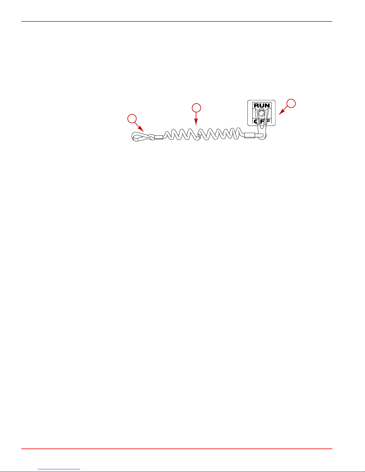
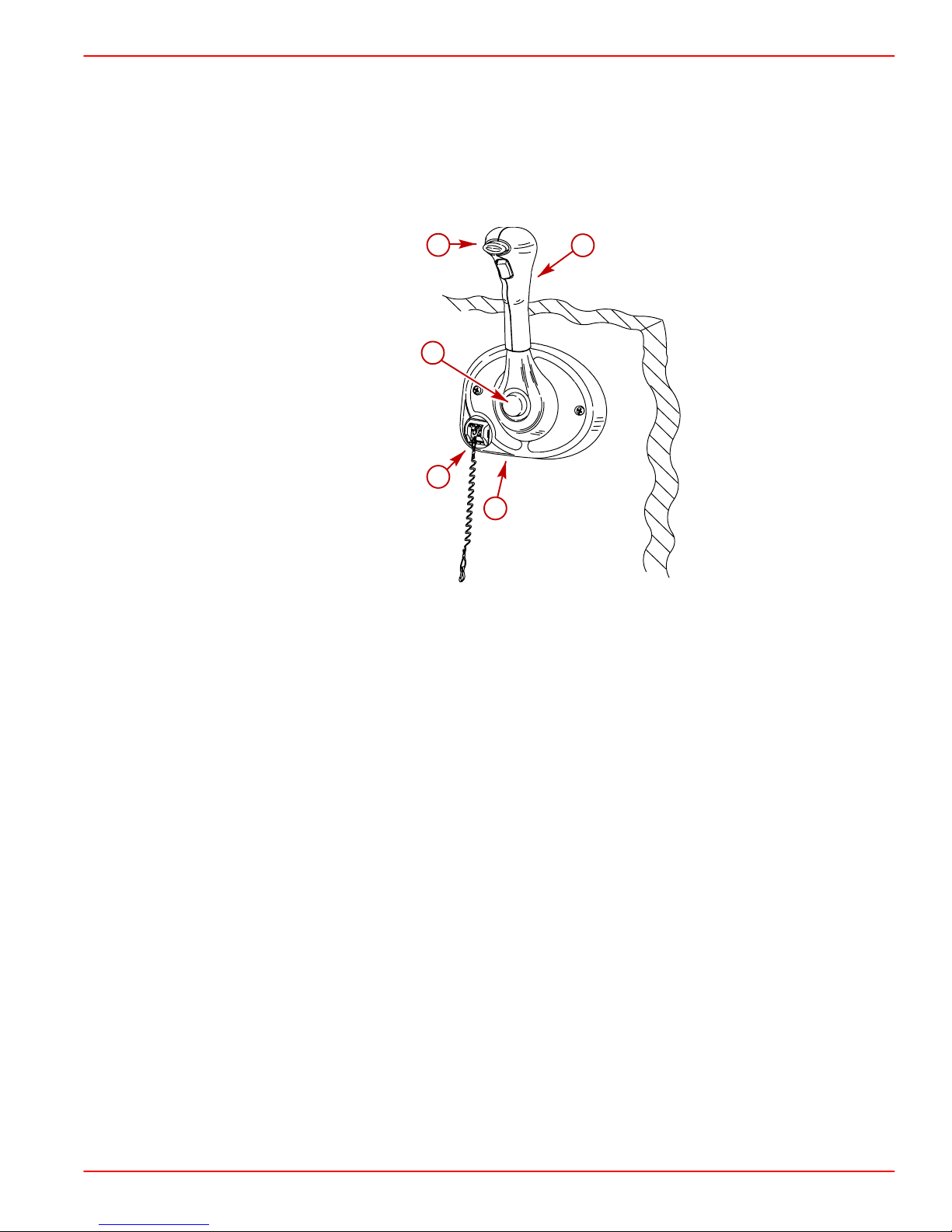
Lanyard Stop Switch
The purpose of a lanyard stop switch is to turn off the engine when the operator moves
outside the operator’s position (as in accidental ejection from the operator’s position).
SECTION 2
b
c
74608
a-Stop switch
b-Lanyard
c-Clips to the operator
Accidental ejections, such as falling overboard, are more likely to occur in:
• low sided sport boats
• bass boats
• high performance boats
Accidental ejections can also occur from:
• poor operating practices
• sitting on the seat or gunwale at planing speeds
• standing at planing speeds
a
• operating at planing speeds in shallow or obstacle infested waters
• releasing your grip on the steering wheel that is pulling in 1 direction
• consuming alcohol or drugs
• high speed boating maneuvers
Some remote control units are equipped with a lanyard stop switch, if your remote control
is not equipped with a lanyard stop switch one can be installed on the dashboard or side
adjacent to the operator’s position. The lanyard is a cord usually 1.2 - 1.5 m (4 - 5 ft) long
when stretched out with an element on 1 end made to be inserted into the switch and a snap
on the other end for attaching to the operator. The lanyard is coiled to make it as short as
possible to minimize the likelihood of entanglement with nearby objects. It stretches to
minimize the likelihood of accidental activation should the operator choose to move around
in an area close to the normal operator’s position. To shorten the lanyard, wrap it around
the operator’s wrist or leg, or tie a knot in the lanyard.
Page 10 CMD-4081877 / 90-865861040 MARCH 2004
Page 19
SECTION 2
GETTING TO KNOW YOUR POWER PACKAGE
Activation of the lanyard stop switch will stop the engine immediately, but the boat will
continue to coast for some distance depending upon the velocity and degree of any turn at
shut down. However, the boat will not complete a full circle. While the boat is coasting, it can
cause injury to anyone in the boat’s path as seriously as the boat would when under power.
We strongly recommend that other occupants be instructed on proper starting and operating
procedures should they be required to operate the engine in an emergency (e.g. if the
operator is accidentally ejected).
WARNING
Avoid contact with the boat hull and propeller from accidental ejection. Personal
injury or death could occur. Always properly connect both ends of the lanyard stop
switch.
Accidental or unintended activation of the switch during normal operation is also a
possibility. This could cause any, or all, of the following potentially hazardous situations:
• Occupants could be thrown forward due to unexpected loss of forward motion, a
particular concern for passengers in the front of the boat who could be ejected over
the bow and possibly struck by the gear case or propeller.
• Loss of power and directional control in heavy seas, strong current or high winds.
• Loss of control when docking.
WARNING
Avoid abrupt deceleration of the boat from lanyard stop switch activation. Boat
damage and personal injury or death could occur. NEVER leave the operator’s
station with the engine operating and in gear.
CMD-4081877 / 90-865861040 MARCH 2004 Page 11
Page 20
GETTING TO KNOW YOUR POWER PACKAGE
00000 was 0012.2
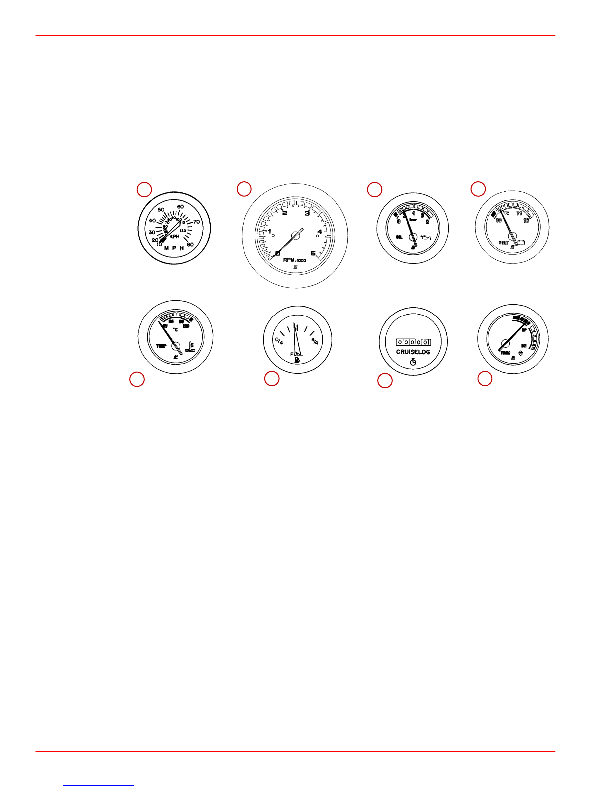
Instrumentation
INSTRUMENTS
The following is a brief explanation of instrumentation typically found on some boats. The
owner/operator should be familiar with all instruments and their functions on the boat.
Because of the large variety of instrumentation and manufacturers, you should have your
boat dealer explain the particular gauges and normal readings that will appear on your style
gauges.
a b c d
SECTION 2
70514
71856
e f g h
70518
70519
71856
70521
Typical
a-Speedometer
b-Tachometer
c-Oil pressure gauge
d-Battery meter
e-Coolant temperature gauge
f-Fuel gauge
g-Hour meter
h-Power trim gauge
Speedometer: Indicates boat speed.
Tachometer: Indicates engine rpm.
Oil Pressure Gauge: Indicates engine oil pressure.
Battery Meter: Indicates battery voltage.
71856
71856
Coolant Temperature Gauge: Indicates engine operating temperature.
Fuel Gauge: Indicates quantity of fuel in tank.
Hour Meter: Records engine operating time.
Power Trim Gauge: Indicates sterndrive unit angle (trim up/out and down/in). Sterndrive
Models only.
Page 12 CMD-4081877 / 90-865861040 MARCH 2004
Page 21
SECTION 2
a modified CD934 and CD860
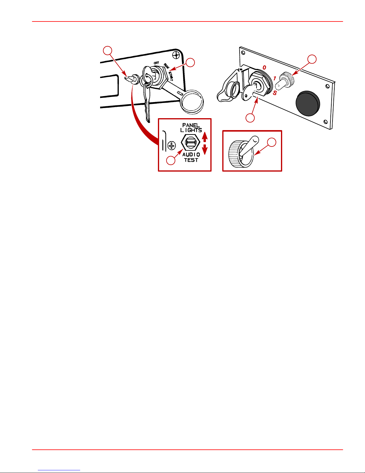
SWITCHES
GETTING TO KNOW YOUR POWER PACKAGE
b
a
b
a
73547
c
b
71891
70522
79996
Typical switches
a-Key switch
b-Panel lights / audio test switch
c-Bilge blower switch
Key Switch - has three positions.
1. OFF - In the OFF position, all electrical circuits are off and engine cannot be started. The
engine is stopped when the key switch is turned to the OFF position.
2. RUN - In the RUN position, all electrical circuits, indicator lamps, automatic preheating
(if equipped) and all instruments are operational.
3. START - In the START position the engine can be started.
NOTE: Key can only be removed in the OFF position.
Panel Lights / Audio Test Switch - has three positions; in the NORMAL position all
electrical circuits operate in a standard fashion (as described above). With switch toggled
UP the instrumentation lights are all illuminated. When the switch is toggled DOWN the
audio warning horn will sound allowing the operator to perform a test of the audio warning
horn.
Bilge Blower Switch: Operates bilge blower.
CMD-4081877 / 90-865861040 MARCH 2004 Page 13
Page 22

GETTING TO KNOW YOUR POWER PACKAGE
CE479 and CD860
ENGINE MONITORING FEATURES
n
a b c d e
Typical
a-Malfunction indicator lamp
b-Water-in-fuel warning lamp, if equipped
c-Coolant temperature warning lamp
d-Oil pressure warning lamp
e-Charge indicator lamp
f-Preheat indicator lamp
The appropriate lamp functions as follows:
Malfunction Indicator Lamp (MIL) - additional lamp indicates when a problem exists, or
a malfunction has occurred, that requires service.
SECTION 2
77359
f
Water-In-Fuel Warning Lamp, if equipped - indicates water is present in fuel filter and that
fuel filter requires service.
Coolant Temperature Warning Lamp - indicates excessive engine coolant temperature
if lamp illuminates while engine is running, or transmission fluid temperature is too high
Refer to the following note.
NOTE: The audio warning alarms are wired in a parallel circuit. If an alarm sounds while the
engine is operating, quickly observe the coolant temperature gauge. If coolant temperature
gauge reading is normal this may be an indication of excessive transmission temperature.
The cause should be determined and corrected.
Oil Pressure Warning Lamp - indicates low engine oil pressure if lamp illuminates while
engine is operating.
Charge Indicator Lamp - indicates a problem with charging system if lamp illuminates
while engine is operating. Lamp will be on when key switch is in RUN and engine is not
operating. When engine starts, light should go off.
Preheat Indicator Lamp - indicates when the glow plugs, if equipped, are preheating the
combustion chambers. When the engine is cold the timed preheat period begins when the
key switch is turned to RUN. The light stays on until the preheat period is complete. The
engine can be started only after the light goes out.
Page 14 CMD-4081877 / 90-865861040 MARCH 2004
Page 23
SECTION 2
0014
Remote Controls
Your boat may be equipped with a Mercury Precision Parts or Quicksilver remote controls.
All controls may not have all features shown. Consult your dealer for a description and/or
demonstration of your remote control.
0015.03
PANEL MOUNTED
GETTING TO KNOW YOUR POWER PACKAGE
a
b
c
d
a-Neutral lock button
b-Throttle only button
c-Lanyard stop switch
d-Control handle throttle friction screw
e-Control handle
e
77019
Neutral Lock Button - Prevents accidental shift and throttle engagement. Neutral lock
button must be pushed IN to move the control handle out of NEUTRAL.
Throttle Only Button - Allows engine throttle advancement without shifting the engine. This
is done by disengaging the shift mechanism from the control handle. The throttle only button
can be depressed only when the remote control handle is in the NEUTRAL position, and
should only be used to assist in starting the engine.
Lanyard Stop Switch - Turns the ignition OFF whenever the operator (when attached to
the lanyard) moves far enough away from the operator’s position to activate the switch.
Refer to Lanyard Stop Switch for information on the use of this switch.
Control Handle Throttle Friction Screw - This screw (located behind the bezel cover) can
be adjusted to increase or decrease the tension on the control handle. This will help prevent
slipping of the remote control handle. Turn screw clockwise to increase tension and
counterclockwise to decrease tension. Adjust to tension desired.
Control Handle - Operation of the shift and throttle are controlled by the movement of the
control handle. Push the control handle forward from NEUTRAL with a quick firm motion to
the first detent for FORWARD gear. Continue pushing forward to increase speed. Pull the
control handle back from NEUTRAL with a quick firm motion to the first detent for REVERSE
gear and continue pushing back to increase speed.
CMD-4081877 / 90-865861040 MARCH 2004 Page 15
Page 24
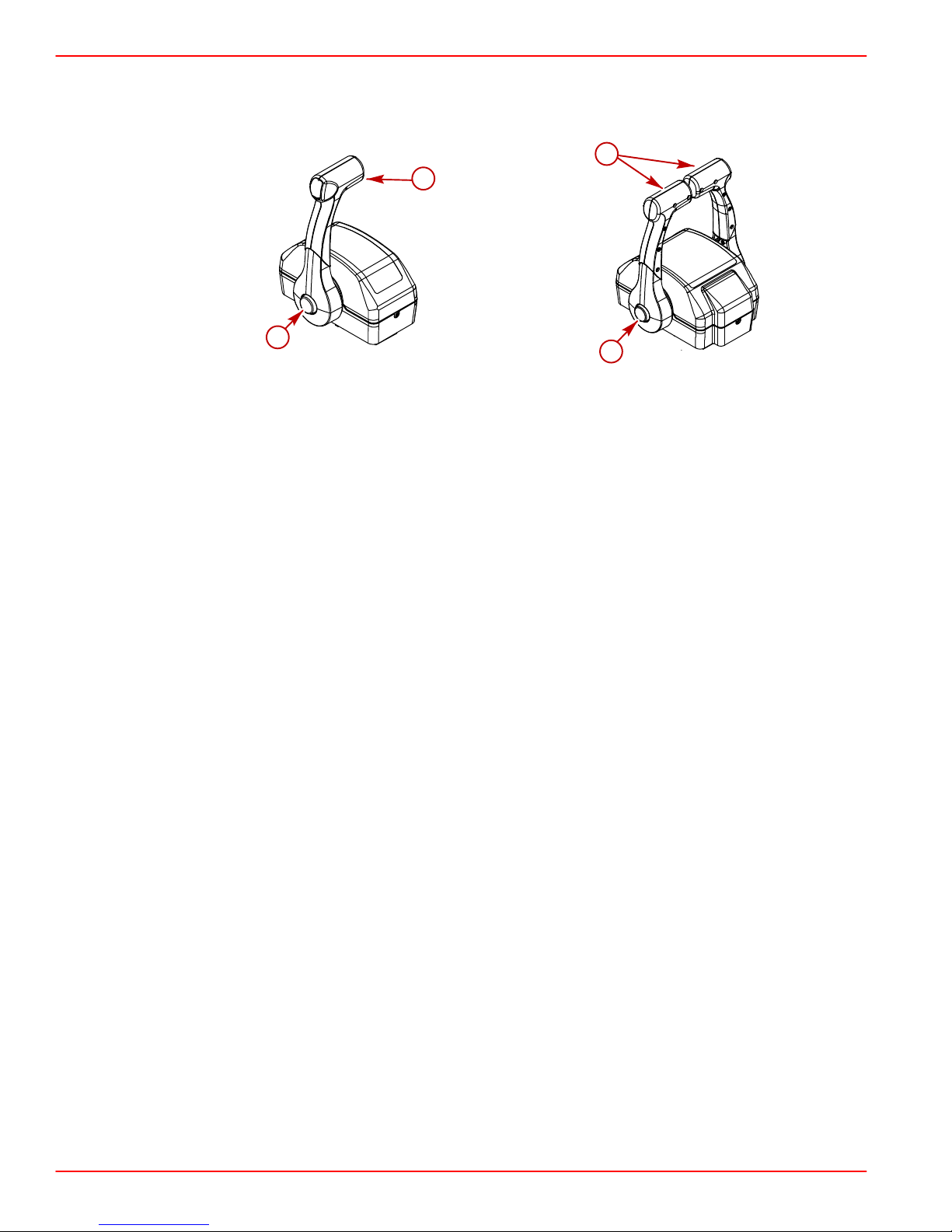
GETTING TO KNOW YOUR POWER PACKAGE
0242.01
CONSOLE MOUNTED
SECTION 2
b
b
a
a
79769
a-Throttle only button
b-Control handles
Throttle Only Button - Allows engine throttle advancement without shifting the engine. This
is done by disengaging the shift mechanism from the control handle. The throttle only button
can be depressed only when the remote control handle is in the NEUTRAL position, and
should only be used to assist in starting the engine.
Control Handle Tension Adjustment Screw - This screw can be adjusted to increase or
decrease the tension on the control handle (cover must be removed to adjust). This will help
prevent slipping of the remote control handle. Turn screw clockwise to increase tension and
counterclockwise to decrease tension. Adjust to tension desired.
Control Handles - Operation of the the shift and throttle are controlled by the movement
of the control handle. Push the control handle forward from NEUTRAL with a quick firm
motion to the first detent for FORWARD gear and continue pushing forward to increase
speed. Pull the control handle back from NEUTRAL with a quick firm motion to the first
detent for REVERSE gear and continue pushing back to increase speed.
79770
Page 16 CMD-4081877 / 90-865861040 MARCH 2004
Page 25
SECTION 2
00000 was 0018.01 w / CMD change
Electrical System Overload Protection
If an electrical overload occurs, a fuse will blow or the circuit breaker will trip open. The cause
must be found and corrected before replacing the fuse or resetting the circuit breaker.
NOTE: In an emergency, when the engine must be operated and the cause for the high
current draw cannot be located and corrected, turn OFF or disconnect all accessories
connected to the engine and instrumentation wiring. Reset the circuit breaker. If the breaker
remains open, the electrical overload has not been eliminated. Further checks must be
made on the electrical system. Contact your authorized Cummins MerCruiser Diesel dealer
/ distributor.
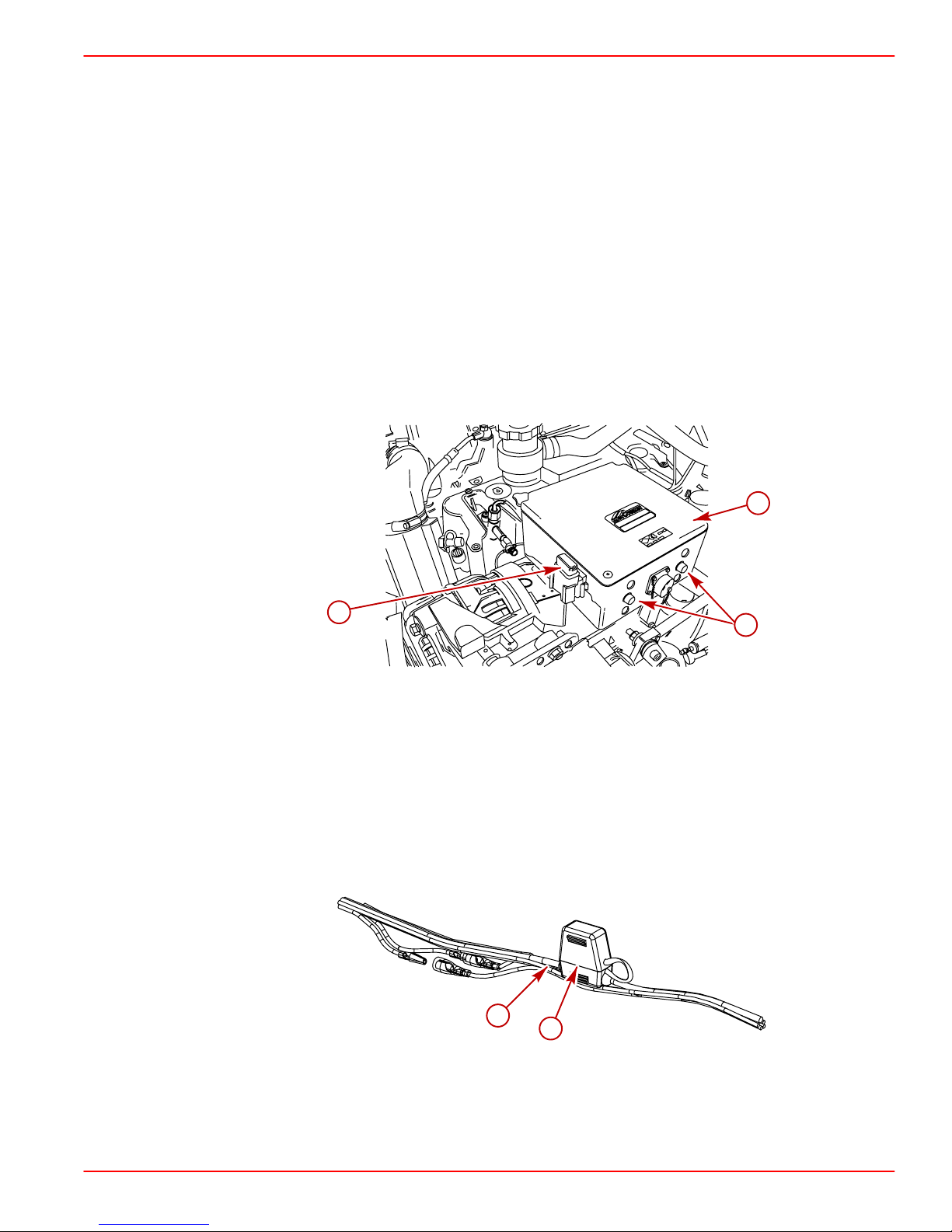
00000 was CD862
1. Two 60 amp circuit breakers provide protection for engine wiring harness and
instrumentation power lead. Reset by pushing RESET button IN (on outside of electrical
box).
2. The Engine Control Module (ECM) is protected from overload by a 5 amp in-line fuse
inside the electrical box. Additional fuses are located inside the electrical box.
GETTING TO KNOW YOUR POWER PACKAGE
a
c
b
79930
a-Electrical box
b-Circuit breaker
c-ECM fuse
3. A 20 amp. fuse located in-line on key switch power supply wire and protects the
instrumentation and wiring should an electrical overload occur. If an overload occurs,
the fuse will burn out. Check blown (burned) fuse if key is turned to RUN or START and
instruments do not work and/or if switches do not function (and a circuit breaker is not
tripped).
a-Key switch power supply wire
b-20 amp. fuse holder
CMD-4081877 / 90-865861040 MARCH 2004 Page 17
a
b
77421
Page 26
GETTING TO KNOW YOUR POWER PACKAGE
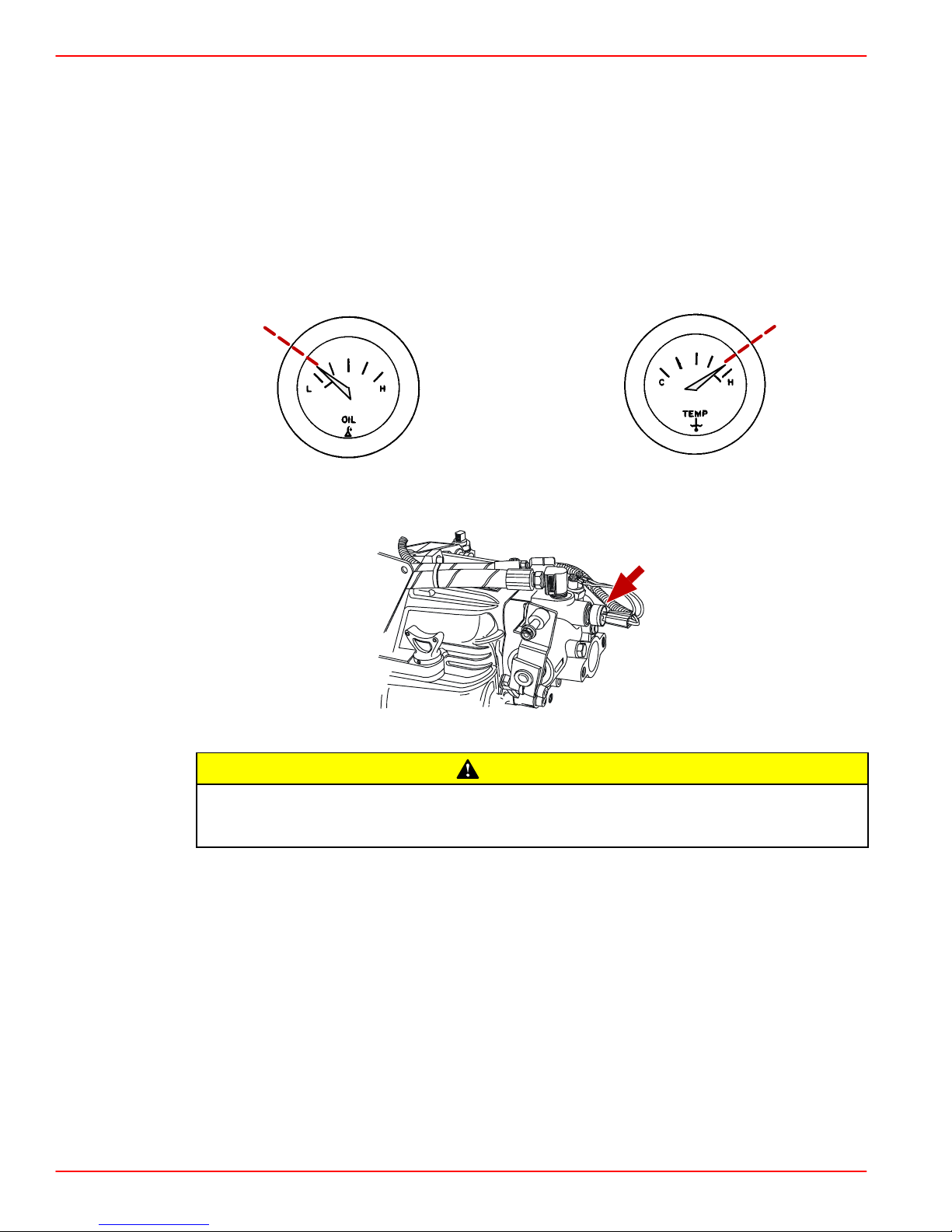
CE480
Audio Warning System
Your Cummins MerCruiser Diesel power package may be equipped with an Audio Warning
System. The Audio Warning System will not protect the engine or transmission from
damage. It is designed to warn the operator that a problem has occurred.
The audio warning system will sound with a continuous alarm if one of the following occurs:
• Engine oil pressure too low
• Coolant temperature too hot
• Transmission fluid temperature too hot
SECTION 2
Typical oil pressure gauge Typical coolant temperature gauge
Typical transmission fluid temperature switch
Operation of the engine after the audio warning system alarm has sounded could
result in damage to the power package. Do not operate engine once the alarm has
sounded EXCEPT TO AVOID A HAZARDOUS SITUATION.
If the alarm sounds, stop the engine immediately. Investigate the cause and correct it, if
possible. If the cause cannot be determined, consult your authorized Cummins MerCruiser
Diesel dealer / distributor.
00000 – a modified 0128 from CE480
TESTING THE AUDIO WARNING SYSTEM
70516
70518
79753
CAUTION
1. Turn the ignition switch to the ON position without cranking the engine.
2. Engage the audio test switch and hold.
3. Listen for the alarm to sound indicating that the system is functioning correctly.
Page 18 CMD-4081877 / 90-865861040 MARCH 2004
Page 27
SECTION 2
00000 was 0220.0
Emissions Information
Exhaust Gas Emissions Certificate (Europe Only)
A tamper-resistant label is affixed to the engine at time of manufacture by Cummins
MerCruiser Diesel. In addition to the required exhaust gas emissions certificate number, the
label lists the engine serial number, engine family, maximum rpm, engine power, and weight.
Please note that the exhaust gas emissions certification will not affect the fit, function, or
performance of the engines. Boatbuilders and Dealers may not remove the label or the part
it is affixed to before sale. If modifications are necessary, contact Cummins MerCruiser
Diesel about the availability of replacement decals before proceeding.
GETTING TO KNOW YOUR POWER PACKAGE
a-Engine serial number
b-Engine family
c-Maximum rpm
d-Power and weight
e-“IMO” - Exhaust Gas Emissions Certificate Number
Owner Responsibility
The owner/operator is not to modify the engine in any matter that would alter the horsepower
or allow exhaust gas emission levels to exceed their predetermined factory specifications.
SERIAL NUMBER
a
b
c
H
d
P
L
B
MARINE POWER
EUROPE INC
MADE IN ITALY
MAX
RPM
K
W
K
G
d
e
78445
CMD-4081877 / 90-865861040 MARCH 2004 Page 19
Page 28

GETTING TO KNOW YOUR POWER PACKAGE
SECTION 2
NOTES:
Page 20 CMD-4081877 / 90-865861040 MARCH 2004
Page 29

SECTION 3
SECTION 3 - ON THE WATER
Table of Contents
ON THE WATER
Safe Boating Suggestions 22. . . . . . . . . . . . . .
Be Alert To Carbon Monoxide
Poisoning 24. . . . . . . . . . . . . . . . . . . . . . . . . . .
Good Ventilation 25. . . . . . . . . . . . . . . . . . .
Poor Ventilation 25. . . . . . . . . . . . . . . . . . . .
Basic Boat Operation 26. . . . . . . . . . . . . . . . . . .
Launching And Boat Operation Care 26. . . .
Duty Cycle Rating 27. . . . . . . . . . . . . . . . . . . .
Pleasure Duty Rating 27. . . . . . . . . . . . . . .
Operation Chart - 2.8 EI 200 28. . . . . . . . . . .
Starting, Shifting and Stopping -
2.8 EI 200 29. . . . . . . . . . . . . . . . . . . . . . . . . . .
Before Starting The Engine 29. . . . . . . . . .
Starting A Cold Engine 30. . . . . . . . . . . . . .
Engine Warm Up 30. . . . . . . . . . . . . . . . . . .
Engine Shut-Down (Stopping) 31. . . . . . .
Freezing Temperature And Cold
Weather Operation 32. . . . . . . . . . . . . . . . . . .
Drain Plug and Bilge Pump 32. . . . . . . . . . . .
Protecting People In The Water 33. . . . . . . . .
While You Are Cruising 33. . . . . . . . . . . . . . . .
While Boat Is Stationary 33. . . . . . . . . . . . . . .
High-Speed And High-Performance
Boat Operation 33. . . . . . . . . . . . . . . . . . . . . . . .
Passenger Safety Message - Pontoon
And Deck Boats 34. . . . . . . . . . . . . . . . . . . . . . .
Wave And Wake Jumping 35. . . . . . . . . . . . . . .
Impact With Underwater Hazards 36. . . . . . . .
Conditions Affecting Operation 37. . . . . . . . .
Weight Distribution (Passengers And
Gear) Inside The Boat 37. . . . . . . . . . . . . . . .
Bottom Of Boat 37. . . . . . . . . . . . . . . . . . . . . . .
Elevation And Climate 37. . . . . . . . . . . . . . . . .
Propeller Selection 38. . . . . . . . . . . . . . . . . . . .
Getting Started 39. . . . . . . . . . . . . . . . . . . . . . . . .
Initial Break-In Procedure 39. . . . . . . . . . . . . .
20-Hour Break-In Period 39. . . . . . . . . . . . . . .
After Break-In Period 40. . . . . . . . . . . . . . . . . .
End of First Season Checkup 40. . . . . . . . . .
3
CMD-4081877 / 90-865861040 MARCH 2004 Page 21
Page 30

ON THE WATER
00000 was 0022 w / CMD changes orCE554
Safe Boating Suggestions
In order to safely enjoy the waterways, familiarize yourself with local and all other
governmental boating regulations and restrictions and also consider the following
suggestions.
• Know and obey all nautical rules and laws of the waterways.
Cummins MerCruiser Diesel strongly recommends that all powerboat operators complete
a boating safety course. Courses are offered in the U.S.A. by: The U.S. Coast Guard
Auxiliary, The Power Squadron, The Red Cross and your state or provincial boating law
enforcement agency. Inquiries may be made to the Boating Hotline at 1-800-368-5647 or
the Boat U.S. Foundation at 1-800-336-BOAT.
You should also review the NMMA Sources of Waterway Information booklet. It lists regional
sources of safety, cruising and local navigation and is available at no charge by writing to:
Sources of Waterway Information
National Marine Manufacturers Association
410 N. Michigan Avenue
Chicago, IL 60611 U.S.A.
SECTION 3
• Perform safety checks and required maintenance. Follow a regular schedule and
ensure that all repairs are properly made.
• Check safety equipment on board. Here are some suggestions of the types of
safety equipment to carry when boating:
Approved fire extinguishers Paddle or oar
Signal devices: flashlight, rockets or
flares, flag and whistle or horn
Spare propeller, thrust hubs, and an
appropriate wrench
Tools necessary for minor repairs First aid kit and instructions
Anchor and extra anchor line Water-proof storage containers
Manual bilge pump and extra drain
plugs
Spare operating equipment, batteries,
bulbs and fuses
Drinking water Compass and map or chart of the area
Transistor radio
Page 22 CMD-4081877 / 90-865861040 MARCH 2004
Page 31

SECTION 3
ON THE WATER
• Watch for signs of weather change and avoid foul weather and rough-sea
boating.
• Tell someone where you are going and when you expect to return.
• Passenger boarding. Stop the engine whenever passengers are boarding,
unloading or are near the back (stern) of the boat. Shifting the drive unit into neutral
is not sufficient.
• Use personal flotation devices. Federal Law requires that there be a U. S. Coast
Guard approved, wearable-type life jacket (personal flotation device), correctly sized
and readily accessible for every person on board, plus a throwable cushion or ring.
We strongly advise that everyone wear a life jacket at all times while in the boat.
• Prepare other boat operators. Instruct at least 1 person on board in the basics of
starting and operating the engine and boat handling in case the driver becomes
disabled or falls overboard.
• Do not overload your boat. Most boats are rated and certified for maximum load
(weight) capacities (refer to your boat capacity plate). Know your boat’s operating
and loading limitations. Know if your boat will float if full of water. When in doubt,
contact your authorized Cummins MerCruiser Diesel dealer / distributor or the boat
manufacturer.
• Ensure that everyone in the boat is properly seated. Do not allow anyone to sit or
ride on any part of the boat that was not intended for such use. This includes the
backs of seats, gunwales, transom, bow, decks, raised fishing seats and any rotating
fishing seat; anywhere that sudden unexpected acceleration, sudden stopping,
unexpected loss of boat control or sudden boat movement could cause a person to
be thrown overboard or into the boat. Ensure that all passengers have a proper seat
and are in it before any boat movement.
• Never be under the influence of alcohol or drugs while boating (it is the law).
They impair your judgment and greatly reduce your ability to react quickly.
CMD-4081877 / 90-865861040 MARCH 2004 Page 23
Page 32

ON THE WATER
• Know your boating area and avoid hazardous locations.
• Be alert. The operator of the boat is responsible by law to “maintain a proper lookout
by sight and hearing.” The operator must have an unobstructed view particularly to
the front. No passengers, load or fishing seats should block the operators view when
operating the boat above idle or planing transition speed. Watch out for others, the
water and your wake.
• Never drive your boat directly behind a water skier in case the skier falls. As an
example, your boat traveling at 40 km/h (25 mph) will overtake a fallen skier who
was 61 m (200 ft) in front of you in 5 seconds.
• Watch fallen skiers. When using your boat for water skiing or similar activities,
always keep a fallen or down skier on the operator’s side of the boat while returning
to attend to the skier. The operator should always have the down skier in sight and
never back up to the skier or anyone in the water.
• Report accidents. Boat operators are required by law to file a Boating Accident
Report with their state boating law enforcement agency when their boat is involved in
certain boating accidents. A boating accident must be reported if (1) there is loss of
life or probable loss of life, (2) there is personal injury requiring medical treatment
beyond first aid, (3) there is damage to boats or other property where the damage
value exceeds $500.00 or (4) there is complete loss of the boat. Seek further
assistance from local law enforcement.
0023
Be Alert To Carbon Monoxide Poisoning
SECTION 3
Carbon monoxide is present in the exhaust fumes of all internal combustion engines
including the outboards, sterndrives and inboard engines that propel boats, as well as the
generators that power various boat accessories. Carbon monoxide is a deadly gas that is
odorless, colorless and tasteless.
Early symptoms of carbon monoxide poisoning, which should not be confused with
seasickness or intoxication, include headache, dizziness, drowsiness and nausea.
WARNING
Avoid prolonged exposure to carbon monoxide. Carbon monoxide poisoning can
lead to unconsciousness, brain damage or death. Ensure that the boat, while at rest
or underway, is well ventilated.
Page 24 CMD-4081877 / 90-865861040 MARCH 2004
Page 33

SECTION 3
0024.01
GOOD VENTILATION
Ventilate the passenger area by opening the side curtains or forward hatches to remove
fumes.
ON THE WATER
0025.01
POOR VENTILATION
Under certain conditions, permanently enclosed or canvas enclosed cabins or cockpits with
insufficient ventilation may draw in carbon monoxide. Install one or more carbon monoxide
detectors in your boat.
Although the occurrence is rare, on a very calm day, swimmers and passengers in an open
area of a stationary boat that contains or is near an operating engine may be exposed to
a hazardous level of carbon monoxide.
mc79553
Courtesy of ABYC
Example of desired air flow through the boat
a
mc79554
b
Example of poor ventilation while a boat is stationary:
a-Operating the engine when the boat is moored in a confined space.
b-Mooring close to another boat with its engine operating.
Courtesy of ABYC
Example of poor ventilation while a boat is moving:
a-Operating the boat with the trim angle of the bow too high.
b-Operating the boat with no forward hatches open (station wagon effect).
CMD-4081877 / 90-865861040 MARCH 2004 Page 25
a
mc79556
b
Courtesy of ABYC
Page 34

ON THE WATER
0026
Basic Boat Operation
0027.1
Launching And Boat Operation Care
To avoid possible ingestion of water that can damage engine components:
• Do not turn the ignition key off when the engine is above idle speed.
w When launching your boat from a steep ramp, enter the water slowly.
• Do not use the lanyard stop switch to shut off the engine above idle speed.
• When coming off plane, if a large following wave may roll over the boat’s
transom, apply a short, light burst of throttle to minimize the wave action against
the stern of the boat.
• Do not come off plane quickly, shift into reverse and shut off engine.
IMPORTANT: Install bilge drain plug prior to launching boat.
SECTION 3
CAUTION
Page 26 CMD-4081877 / 90-865861040 MARCH 2004
Page 35

SECTION 3
Cycle 5 / ICOMIA 83-28
CE465 or similar to CD908
Duty Cycle Rating
IMPORTANT: Damage caused by improper application or failure to operate the power
package within the specified operating parameters, will not be covered by the
Cummins MerCruiser Diesel Limited Warranty.
It is the responsibility of the boat manufacturer and/or the installing dealer to ensure that the
power package is properly applied. In all cases, the power package must be equipped with
a propeller that will allow the engine to operate at wide open throttle (WOT) at the Rated
Engine rpm.
PLEASURE DUTY RATING
The Pleasure Duty Rating applies to recreational planing craft used exclusively for pleasure
and recreation. Typical applications include pleasure craft such as sailboats, ski boats,
runabouts, speedboats, and other planing hulls. Application must conform to the Pleasure
Craft / Recreational duty cycle shown (EPA Mode Number Cycle 5 / ICOMIA 83-28 Duty
Cycle).
ON THE WATER
EPA Mode Number
Modes
-
Duty Cycle
1 2 3 4 5
Engine Speed (Percent of WOT) 100 91 80 63 Idle
Engine Power (Percent of Total) 100 75 50 25 0
Time At Given Mode
8 13 17 32 30
(Percent Of Total Operating Time)
a
e
b
c
d
Chart showing full power operation is limited to a maximum of 1 of 12 hours
a-Mode 1: 1.0 hour (8 percent)
b-Mode 2: 1.5 hours (13 percent)
c-Mode 3: 2.0 hours (17 percent)
d-Mode 4: 4.0 hours (32 percent)
e-Mode 5: 3.5 hours (30 percent)
79175
CMD-4081877 / 90-865861040 MARCH 2004 Page 27
Page 36

ON THE WATER
00000 was CD864 with header change
Operation Chart - 2.8 EI 200
SECTION 3
STARTING
PROCEDURE
Open engine hatch. Air
out bilge completely.
Turn battery switch ON,
if so equipped.
Turn on and run engine
compartment bilge
blower, if so equipped,
for five minutes.
Check for leaks - fuel,
oil, water, fluid, etc.
Open fuel shutoff valve,
if so equipped.
Open seacock, if so
equipped.
AFTER
STARTING
Observe all gauges and
warning lights to check
condition of engine. If
not normal, stop engine.
Check for fuel, oil,
water, fluid, and exhaust
leaks, etc.
Check shift and throttle
control operation.
Check steering
operation.
WHILE
UNDERWAY
Frequently observe all
gauges and indicator
lights to monitor
engine condition.
STOPPING &
SHUT DOWN
Shift remote control
lever to neutral position.
Operate engine at idle
speed several minutes
to allow the
turbocharger and
engine to cool.
Turn key switch to OFF
position.
Turn battery switch, if so
equipped, to OFF.
Close fuel shutoff valve,
if so equipped.
Close seacock, if so
equipped.
Prime fuel injection
system, if necessary.
Turn key switch to RUN
and check that lights
and indicator lamps
come on.
Turn key switch to START,
after indicator lamp for the
glow plugs (if so
equipped) ceases.
Release key when the
engine starts.
Check that charge
indicator and oil pressure
indicator lamps cease
AFTER engine starts.
Warm-up engine at idle
rpm for several minutes.
Flush seawater cooling
circuit, if operating in
saltwater area.
Page 28 CMD-4081877 / 90-865861040 MARCH 2004
Page 37

SECTION 3
00000 was CD863 with changes to Engine Oil bullet point
Starting, Shifting and Stopping - 2.8 EI 200
WARNING
Do not use volatile starting aids, such as Ether, Propane, or Gasoline in the engine
air intake system. Explosion hazard resulting from ignition of vapors by glow plugs
could cause severe personal injury and engine damage.
CAUTION
It is good practice to ventilate the engine compartment prior to servicing any engine
components to remove any fuel vapors which may cause difficulty breathing or be
an irritant.
BEFORE STARTING THE ENGINE
CAUTION
Do not operate engine without water flowing thru seawater pickup pump, as pump
impeller may be damaged and subsequent overheating damage to engine or drive
unit may result.
IMPORTANT: Observe the following before starting:
• Provide water to the seawater pickup pump.
ON THE WATER
• Never operate the starter motor longer than 15 seconds at a time, to avoid
overheating the starter motor. If engine does not start, wait 1 minute to allow
the starter motor to cool; then, repeat starting procedure.
• Ensure engine crankcase is filled to correct level with the proper grade of oil
for the prevailing temperature. Refer to Specifications - Engine Oil.
• Ensure all electrical connections are secure.
• Check the air cleaner for proper installation of filter element.
1. Check all items listed in the Maintenance Schedules and Operation Chart. Refer to Table
Of Contents.
2. Perform any other necessary checks, as indicated by your dealer, or specified in your
boat owner’s manual.
CMD-4081877 / 90-865861040 MARCH 2004 Page 29
Page 38

ON THE WATER
00000 was CE298 w changes in all with revision bars
STARTING A COLD ENGINE
IMPORTANT: Always check fluid levels before starting the engine. Refer to
Maintenance Chart.
1. Turn on and run engine compartment bilge blower (if so equipped) for five minutes. Or,
open engine hatch to air out bilge before attempting to start engine.
2. Place control handle in NEUTRAL.
3. If engine has not been run for a period of time and will not readily start with the standard
starting procedure, there is a hand pump/primer knob located on the fuel filter header.
Move knob up and down four or five strokes. Attempt to start engine following normal
procedure.
4. Turn key switch to the RUN position. Observe indicator lamp for glow plugs, if so
equipped. When cylinder temperature is great enough to sustain combustion, the
indicator lamp will go off and the engine can be started.
5. Turn key switch to START position. Release the key and allow the switch to return to
RUN position when the engine starts.
IMPORTANT: Within seconds after starting the engine, the oil pressure should
exceed 10 psi (69 kPa) minimum. If the oil pressure does not meet these minimum
limits, stop the engine, locate and correct the problem, or see your authorized
Cummins MerCruiser Diesel dealer or distributor if you are unable to determine the
problem.
SECTION 3
6. Ensure charge indicator and oil pressure warning lamps are off.
Do not increase the engine speed until the oil pressure gauge indicates normal.
Shut the engine down if oil pressure does not register on the gauge within 20 to 30
seconds after start.
00000 wasCE31 with changes to all
ENGINE WARM UP
Improper or no warm-up of engine can seriously impair the Iife of your diesel
engine.
1. After starting, ensure all instrumentation is functioning properly.
NOTE: It is very important that any engine be warmed up before applying full load.
2. Operate engine for 1 or 2 minutes at fast IDLE (1000-1500 rpm) or until engine
temperature reaches operating temperature before applying full load. The warm-up
period provides time for the lubricating oil to establish a film between moving parts.
NOTE: Engine warm-up time during cold weather can be reduced by operating vessel at
reduced engine speed. Commence normal vessel operation when systems reach operating
temperatures.
CAUTION
CAUTION
3. Inspect the power package for fuel, oil, water and exhaust leaks.
4. After the engine has reached operating temperature, oil pressure should be within range
listed in the engine specifications chart. Stop the engine if oil pressure is not within this
range. Locate and correct the problem, or see your authorized Cummins MerCruiser
Diesel dealer or distributor if you are unable to determine the problem.
Page 30 CMD-4081877 / 90-865861040 MARCH 2004
Page 39

SECTION 3
CE526
STARTING A WARM ENGINE
1. Place control handle in NEUTRAL.
2. Turn key switch to the RUN position.
3. Turn key switch to START position and release when engine starts. Ensure charge
indicator and oil pressure warning lamps go off.
4. Check to ensure all instrumentation is functioning properly and indicating normal
readings
CE483
SHIFTING
Never attempt to shift the transmission unless the engine is at IDLE rpm. Damage
to the transmission could occur.
1. To shift unit, ensure remote control/throttle lever is in NEUTRAL. Move control/shift lever
forward to shift to FORWARD gear, or backward to shift to REVERSE. After shifting the
transmission, advance the throttle to the desired setting.
2. Once underway, engine oil pressure should be within the range listed in the engine
specifications chart at maximum rpm, or wide-open-throttle. Stop the engine if oil
pressure is not within this range. Locate and correct the problem, or see your authorized
Cummins MerCruiser Diesel dealer / distributor if you are unable to determine the
problem.
ON THE WATER
CAUTION
CD366
ENGINE SHUT-DOWN (STOPPING)
1. Place remote control lever in NEUTRAL.
Avoid damaging the turbocharger and engine. Immediate engine shutdown
(stopping) after high load operation may result in permanent turbocharger bearing
damage. Operate the engine at IDLE for several minutes before shut-down.
2. Operate the engine at idle speed for several minutes to allow the turbocharger and
engine to cool.
3. Turn key switch to the OFF position.
CAUTION
CMD-4081877 / 90-865861040 MARCH 2004 Page 31
Page 40

ON THE WATER
CE468
Freezing Temperature And Cold Weather Operation
IMPORTANT: If boat is operated during periods of freezing temperature, precautions
must be taken to prevent freezing damage to power package. Damage caused by
freezing IS NOT
covered by Cummins MerCruiser Diesel Limited Warranty.
CAUTION
Seawater (raw water) section of cooling system MUST BE COMPLETELY drained for
winter storage or immediately after cold weather use, if the possibility of freezing
temperatures exist. Failure to comply may result in trapped water causing freeze
and/or corrosion damage to engine.
In order to operate the engine in temperatures of 0 degrees C (32 degrees F) or lower,
observe the following instructions:
• At the end of each daily operation, COMPLETELY drain seawater section of cooling
system to protect against damage by freezing.
• At the end of each daily operation, drain water from water separator, if equipped. Fill fuel
tank at end of daily operation to prevent condensation.
• Use required permanent-type antifreeze solution to protect components against
damage by freezing.
SECTION 3
• Be sure to use proper cold weather lubrication oil, and be sure the crankcase contains
a sufficient amount.
• Make certain that the battery is of sufficient size and is fully charged. Check that all other
electrical equipment is in optimum condition.
• At temperatures of – 20 degrees C (–4 degrees F) and below, it is recommended that
you use a coolant heater to improve cold starting.
• If operating in arctic temperatures of – 29 degrees C (–20 degrees F) or lower, consult
your Cummins MerCruiser Diesel dealer / distributor for information about special cold
weather equipment and precautions.
Refer to Section 6 for Cold Weather or Extended Storage related information and draining
instructions.
00000 was CE548 or 0031 with CMD
Drain Plug and Bilge Pump
The engine compartment in your boat is a natural place for water to collect. For this reason,
boats are normally equipped with a drain plug and/or a bilge pump. It is very important to
check these items on a regular basis to ensure that the water level does not come into
contact with your power package. Components on your engine will be damaged if
submerged. Damage caused by submersion is not covered by the Cummins MerCruiser
Diesel Limited Warranty.
Page 32 CMD-4081877 / 90-865861040 MARCH 2004
Page 41

SECTION 3
0032
Protecting People In The Water
While You Are Cruising
It is very difficult for a person standing or floating in the water to take quick action to avoid
a boat heading in his/her direction even at slow speed.
Always slow down and exercise extreme caution any time you are boating in an area where
there might be people in the water.
Whenever a boat is moving (coasting) in NEUTRAL/IDLE, there is sufficient force by the
water on the propeller to cause the propeller to rotate. This neutral propeller rotation can
cause serious injury.
While Boat Is Stationary
Stop your engine immediately whenever anyone in the water is near your boat.
Serious injury to the person in the water is likely if contacted by a rotating propeller,
a moving boat, a gear case or any solid device rigidly attached to a moving boat or
gear case.
ON THE WATER
WARNING
Shift into the NEUTRAL/IDLE position and shut off the engine before allowing people to
swim or be in the water near your boat.
0033 w CMD changes
High-Speed And High-Performance Boat Operation
If your boat is considered a high-speed or high-performance boat with which you are
unfamiliar, we recommend that you never operate it at its high speed capability without first
requesting an initial orientation and demonstration ride with your dealer or an operator
experienced with your boat. For additional information, refer to Hi-Performance Boat
Operation booklet (90-849250-R2) from your authorized Cummins MerCruiser Diesel
dealer or distributor.
CMD-4081877 / 90-865861040 MARCH 2004 Page 33
Page 42

ON THE WATER
0131.02
Passenger Safety Message - Pontoon And Deck Boats
WARNING
Avoid serious injury or death from falling over the front end of a pontoon or deck
boat and coming in contact with the boat hull or propeller. Stay back from the front
end of the deck and remain seated while the boat is in motion.
Whenever the boat is in motion, observe the location of all the passengers. Do not allow any
passengers to stand or use seats other than those designated for traveling faster than idle
speed. A sudden reduction in boat speed, such as the result of plunging into a large wave
or wake, a sudden throttle reduction or a sharp change of boat direction, could throw them
over the front of boat. Falling over the front of the boat between the two pontoons will position
them to come into contact with the drive unit.
1. Boats having an open front deck:
a. No one should ever be on the deck in front of the fence while the boat is in motion. Keep
all passengers behind the front fence or enclosure.
b. Persons on the front deck could easily be thrown overboard or persons dangling
their feet over the front edge could get their legs caught by a wave and pulled into
the water.
SECTION 3
mc79555
Incorrect Correct
2. Boats with front-mounted, raised pedestal fishing seats:
a. These elevated fishing seats are not intended for use when the boat is traveling
faster than idle or trolling speed. Sit only in seats designated for traveling at faster
speeds.
b. Any unexpected sudden reduction in boat speed could result in the elevated
passenger falling over the front of the boat.
mc79557
Incorrect Correct
Page 34 CMD-4081877 / 90-865861040 MARCH 2004
Page 43

SECTION 3
0034.01
Wave And Wake Jumping
Avoid serious injury or death from being thrown within or out of a boat when it lands
after jumping a wave or wake. Avoid wave or wake jumping whenever possible.
Instruct all occupants that if a wake or wave jump occurs, get low and hang on to
a boat hand hold.
Operating recreational boats over waves and wakes is a natural part of boating. However,
when this activity is done with enough speed to force the boat hull partially or completely
out of the water, certain hazards arise, particularly when the boat re-enters the water.
The primary concern is the boat changing direction while in the midst of the jump. In such
cases the landing may cause the boat to violently veer in a new direction. Such a sharp
change in direction or turn can cause occupants to be thrown out of their seats or out of the
boat.
ON THE WATER
mc79675
WARNING
There is another less common hazardous result from allowing your boat to launch off of a
wave or wake. If the bow of your boat pitches down far enough while airborne, upon water
contact it may penetrate under the water surface and submarine for an instant. This will bring
the boat nearly to a stop in an instant and can send the occupants flying forward. The boat
may also veer sharply to one side.
CMD-4081877 / 90-865861040 MARCH 2004 Page 35
Page 44

ON THE WATER
0035.02
Impact With Underwater Hazards
Reduce speed and proceed with caution whenever you’re driving a boat in shallow water
areas or in areas where the waters are suspected of having underwater obstacles that could
be struck by the underwater drive components, rudder or the boat bottom. The most
important thing you can do to help reduce injury or impact damage from striking a
floating or underwater object is control the boat speed. Under these conditions, boat
speed should be kept to a minimum planing speed of 24 to 40 km/h (15 to 25 MPH).
Striking a floating/underwater object may result in an infinite number of situations. Some of
these situations could result in the following:
• The boat could move suddenly in a new direction. Such a sharp change in direction or
turn can cause occupants to be thrown out of their seats or out of the boat.
SECTION 3
mc79680
• A rapid reduction in speed. This will cause occupants to be thrown forward, even out of
the boat.
• Impact damage to the underwater drive components, rudder and/or boat.
Keep in mind, one of the most important things you can do to help reduce injury or impact
damage in these situations is control the boat speed. Boat speed should be kept to a
minimum planing speed when driving in waters known to have underwater obstacles.
After striking a submerged object, stop engine as soon as possible and inspect the drive
system for any broken or loose parts. If damage is present or suspected, the power package
should be taken to an authorized dealer for a thorough inspection and necessary repair.
The boat should also be checked for any hull fractures, transom fractures, water leaks.
Operating with damaged underwater drive components, rudder or boat bottom could cause
additional damage to other parts of the power package, or could affect control of the boat.
If continued running is necessary, do so at greatly reduced speeds.
WARNING
Avoid serious injury or death from loss of boat control. Continued boating with
major impact damage can result in sudden component failure with or without
subsequent impacts. Have the power package thoroughly inspected and any
necessary repairs made.
Page 36 CMD-4081877 / 90-865861040 MARCH 2004
Page 45

SECTION 3
0036
Conditions Affecting Operation
Weight Distribution (Passengers And Gear) Inside The Boat
Shifting weight to rear (stern):
• Generally increases speed and engine rpm
• Causes bow to bounce in choppy water
• Increases danger of following wave splashing into the boat when coming off plane
• At extremes, can cause the boat to porpoise
Shifting weight to front (bow):
• Improves ease of planing
• Improves rough water ride
• At extremes, can cause the boat to veer back and forth (bow steer)
0037
Bottom Of Boat
ON THE WATER
To maintain maximum speed, the boat bottom should be:
• Clean, free of barnacles and marine growth
• Free of distortion; nearly flat where it contacts the water
• Straight and smooth, fore and aft
Marine vegetation may accumulate when the boat is docked. This growth must be removed
before operation; it may clog the water inlets and cause the engine to overheat.
0039 w changes to fit these diesel engines
Elevation And Climate
NOTE: Engines equipped with an Electronic Control Module (ECM) reduce the effects of
changes in elevation and climate by automatically adjusting fuel flow for weather conditions
and elevation. ECM controlled engines however, do not compensate for increased loading
or hull conditions.
Elevation and climate changes will affect the performance of your power package. Loss of
performance can be caused by:
• Higher elevations
• Higher temperatures
• Low barometric pressures
• High humidity
For you to have optimum engine performance under changing weather conditions, it is
essential that the engine be propped to allow the engine to operate at or near the top end
of the Rated Engine rpm with a normal boat load during your normal boating weather
conditions.
In most cases, performance can be regained by changing to a lower pitch propeller.
CMD-4081877 / 90-865861040 MARCH 2004 Page 37
Page 46

ON THE WATER
00000 was 0040 or CE464 w rev bar indicated changes
Propeller Selection
The installed propeller must allow the engine to run at the Rated Engine rpm at WOT
to avoid engine damage. Using a propeller that causes the engine to operate below
the Rated Engine rpm can cause piston and/or valve damage (even if the engine is
not operated at WOT). Conversely, using a propeller that allows engine to operate
above the specified Rated Engine rpm can increase fuel consumption and wear and
will not allow engine to produce its rated horsepower.
It is the responsibility of the boat manufacturer and/or the selling dealer to equip the power
package with the correct propellers.
IMPORTANT: The engines covered in this manual are equipped with an ECM that
limits engine rpm. Be sure that propeller being used does not allow engine to run
against the limiter, as a significant loss in performance will result.
NOTE: Use an accurate service tachometer to verify rpm.
Select a propeller that will allow the engine power package to operate at the Rated Engine
rpm with a full load.
If full throttle operation is below the Engine Rated rpm, the propeller must be changed to
prevent loss of performance and possible engine damage. On the other hand, operating an
engine above the Rated Engine rpm will cause higher than normal wear and/or damage.
SECTION 3
CAUTION
After initial propeller selection, the following common problems may require that the
propeller be changed to a lower pitch:
• Warmer weather and greater humidity cause an rpm loss (not as significant on these
models).
• Operating in a higher elevation causes an rpm loss (not as significant on these models).
• Operating with a damaged propeller or dirty boat bottom causes an rpm loss.
• Operating with increased load (additional passengers, pulling skiers).
Page 38 CMD-4081877 / 90-865861040 MARCH 2004
Page 47

SECTION 3
0042
Getting Started
00000 was CD912 or CE555 with different rpms in lists
Initial Break-In Procedure
It is especially important that the following procedure be used on new diesel engines. This
break-in procedure allows the proper seating of the pistons and rings, which greatly reduces
the likelihood of problems.
IMPORTANT: It is recommended that the boat not be accelerated hard until this
procedure has been completed.
IMPORTANT: Never operate the starter motor longer than 15 seconds at a time, to
avoid overheating the starter motor. If engine does not start, wait 1 minute to allow
the starter motor to cool; then, repeat starting procedure.
1. Refer to appropriate Starting, Shifting and Stopping section and start the engine.
Operate the engine at a fast idle until it has reached normal operating temperature.
2. Operate the engine in gear for 3 minutes at each of the following rpms: 1200 rpm, 2400
rpm and 3000 rpm.
3. Operate the engine in gear for 3 minutes at each of the following rpms: 1500 rpm, 2800
rpm and 3400 rpm.
ON THE WATER
4. Operate the engine in gear for 3 minutes at each of the following rpms: 1800 rpm, 3000
rpm and Maximum Rated Full Throttle rpm.
0041 w / change that added last bullet on 20 hour from CE11
20-Hour Break-In Period
IMPORTANT: The first 20 hours of operation is the engine break-in period. Correct
break-in is essential to obtain minimum oil consumption and maximum engine
performance. During this break-in period, the following rules must be observed:
• Do not operate below 1500 rpm for extended periods of time for the first 10 hours.
Shift into gear as soon as possible after starting and advance the throttle above 1500
rpm if conditions permit safe operation.
• Do not operate at one speed consistently for extended periods.
• Do not exceed 3/4 throttle during the first 10 hours. During the next 10 hours,
occasional operation at full throttle is permissible (5 minutes at a time maximum).
• Avoid full throttle acceleration from IDLE speed.
• Do not operate at full throttle until the engine reaches normal operating temperature.
• Frequently check engine oil level. Add oil as needed. It is normal for oil consumption
to be high during the break-in period.
• AT END OF 20-HOUR break-in period, remove break-in oil and replace oil filter. Fill
the engine with the correct grade and viscosity oil.
CMD-4081877 / 90-865861040 MARCH 2004 Page 39
Page 48

ON THE WATER
0043 w / changes – CMD and remove last bullet, see CE475
After Break-In Period
To help extend the life of your Cummins MerCruiser Diesel power package, the following
recommendations should be considered:
• Use a propeller that allows the engine to operate at the Rated Engine rpm at WOT
when at full throttle with a full boat load. Refer to Specifications and Maintenance.
• Operation at 3/4 throttle setting or lower is recommended. Refrain from prolonged
operation at WOT rpm.
0044 w / changes to CMD, or see CE476
End of First Season Checkup
At the end of the first season of operation, contact an authorized Cumins MerCruiser Diesel
dealer / distributor to discuss and/or perform scheduled maintenance items. If you are in an
area where the product is operated continuously, year-round, you should contact your
dealer at the end of the first 100 hours of operation or once yearly, whichever occurs first.
SECTION 3
Page 40 CMD-4081877 / 90-865861040 MARCH 2004
Page 49

SECTION 4
SECTION 4 - SPECIFICATIONS
Table of Contents
SPECIFICATIONS
Fuel Requirements 42. . . . . . . . . . . . . . . . . . . . .
Diesel Fuel In Cold Weather 43. . . . . . . . . . . . .
AntiFreeze/Coolant 43. . . . . . . . . . . . . . . . . . . . .
Engine Oil 45. . . . . . . . . . . . . . . . . . . . . . . . . . . . .
Engine Specifications 46. . . . . . . . . . . . . . . . . .
2.8 EI 200 46. . . . . . . . . . . . . . . . . . . . . . . . . . .
Fluid Specifications 47. . . . . . . . . . . . . . . . . . . .
4
CMD-4081877 / 90-865861040 MARCH 2004 Page 41
Page 50

SPECIFICATIONS
CD164
Fuel Requirements
Electrical system components on this engine are not external ignition protected.
DO NOT STORE OR UTILIZE GASOLINE ON BOATS EQUIPPED WITH THESE
ENGINES, UNLESS PROVISIONS HAVE BEEN MADE TO EXCLUDE GASOLINE
VAPORS FROM ENGINE COMPARTMENT (REF: 33 CFR). Failure to comply could
result in fire, explosion and/or severe personal injury.
FIRE HAZARD: Fuel leakage from any part of the fuel system can be a fire hazard
which can cause serious bodily injury or death. Careful periodic inspection of entire
fuel system is mandatory, particularly after storage. All fuel components including
fuel tanks, whether plastic, metal or fiberglass, fuel lines, primers, fittings, and fuel
filters should be inspected for leakage, soften, hardening, swelling or corrosion.
Any sign of leakage or deterioration requires replacement before further engine
operation.
SECTION 4
WARNING
WARNING
WARNING
Under no circumstances should gasoline, gasohol and/or alcohol be mixed with
diesel fuel for any reason. This mixture of gasoline, gasohol and/or alcohol with
diesel fuel is highly flammable and produces a significant risk to the user.
IMPORTANT: Use of improper or water contaminated diesel fuel can damage your engine seriously. Use of improper fuel is considered misuse of engine, and damage
caused thereby will not be covered by warranty.
Grade 2-D diesel fuel is required, meeting ASTM Standards D975 (or fuel rated Diesel DIN
51601), and having a minimum cetane rating of 45.
The Cetane number is a measure of the ignition quality of diesel fuel. Increasing the cetane
number will not improve overall engine performance, but it may be necessary to raise the
cetane rating for low temperature, or high altitude use. A lower cetane number could cause
hard starting and slower warm-up, and could increase engine noise and exhaust emissions.
NOTE: If your engine suddenly becomes noisy after a fuel fill, you possibly received
substandard fuel with a low cetane rating.
Sulphur content of the above fuel is rated at 0.50% by weight, maximum (ASTM). Limits may
vary in countries outside of the United States.
On intermittent use engines, high sulphur content diesel fuel will greatly increase:
• Corrosion on metal parts.
• Deterioration of elastomer and plastic parts.
• Corrosion and extensive damage, and excessive wear of internal engine parts, par-
ticularly bearings.
• Starting and operating difficulties.
Page 42 CMD-4081877 / 90-865861040 MARCH 2004
Page 51

SECTION 4
00000 was CE16
Diesel Fuel In Cold Weather
Unaltered diesel fuels thicken and gel in cold temperatures, unless treated. Virtually all
diesel fuels are climatized to allow their use in the particular region for that time of the year.
If it becomes necessary to further treat diesel fuel, it is the owner/operator’s responsibility
to add a commercial standard brand anti-gel diesel fuel additive, following that product’s
directions.
CE528
AntiFreeze/Coolant
Alcohol or Methanol base antifreeze or plain water are not recommended for use in
closed cooling section of cooling system at any time.
Because diesel engines are high compression engines and related higher engine operating
temperatures are created, the closed cooling system and engine, including related cooling
passages must remain as clean as possible to provide adequate engine cooling. This can
only be assured by using the proper antifreeze, water, additives and inhibitors. It is
recommended that the closed cooled section of the cooling system be filled with a low
silicate formula of ethylene glycol antifreeze in solution with deionized water. A low silicate
formula prevents antifreeze separation which causes a silicate gelatin to form. This gelatin
will block engine and heat exchanger passages causing engine overheating.
SPECIFICATIONS
CAUTION
The coolant, if not premixed, should be mixed before being added to the closed cooling
system using a proper antifreeze together with deionized water. Common tap water or
softened water contains unwanted minerals which can leave large deposits in the system
that restrict the cooling system efficiency. In addition, additives and inhibitors introduced into
acceptable coolant solutions will form a protective film on internal passages and provide
protection against internal cooling system erosion.
CMD-4081877 / 90-865861040 MARCH 2004 Page 43
Page 52

SPECIFICATIONS
SECTION 4
The closed cooling section should be kept filled year-round with an acceptable
antifreeze/coolant solution. Do not drain closed cooled section for storage, as this will
promote rusting of internal surfaces. If engine will be exposed to freezing temperatures,
ensure that the closed cooled section is filled with a properly mixed antifreeze/coolant
solution, to protect engine and closed cooling system to lowest temperature to which they
will be exposed.
NOTE: A 50/50 antifreeze/coolant solution should be used except when operating where
seawater temperatures are greater than 32 degrees C (90 degrees F), then a 25 / 75
(antifreeze / water) solution can be used for improved cooling performance.
IMPORTANT: The antifreeze/coolant used in these marine engines must be a low
silicate ethylene glycol, containing special additives, and deionized, purified water.
Using other types of engine coolant may cause fouling of the heat exchangers, and
overheating of the engine. Do not combine different types of coolants without
knowing that they are compatible. Refer to the coolant manufacturer’s instructions.
Some acceptable types of antifreeze/coolants are listed in the following table. Refer to
Maintenance Schedules for respective change intervals.
Description
Part Number
Marine Engine Coolant 92-813054A2
Fleetguard Compleat with DCA4
Fleetguard Part Number: CC2825
Obtain Locally
Quantity: 3-3/4 liters, 1 U. S. Gallon
Page 44 CMD-4081877 / 90-865861040 MARCH 2004
Page 53

SECTION 4
Engine
Obtain L
0000 0 was CD865 w changes in table
Engine Oil
ENVIRONMENTAL HAZARD! Discharge of oil or oil waste into the environment is
restricted by law. Do NOT spill oil or oil waste into the environment when using or
servicing your boat. Contain and dispose of oil or oil waste as defined by local authorities.
To help obtain optimum engine performance and to provide maximum protection, the engine
requires engine oil with a rating of HD-SAE-API CG-4 and CH-4.
We strongly recommend the use of:
Description Where Used Part Number
SPECIFICATIONS
CAUTION
15W40 4-cycle Diesel Engine
Oil
Engine crankcase 92-877695K1
This oil is a specially blended 15W-40 oil with Marine Additives, for all temperature
operation. It exceeds requirements for API CF-2, CF-4, CG-4 and CH-4 oils.
Other recommended oils:
Description Where Used Part Number
Shell Myrina
Mopar
Texaco Ursa Super TD
Wintershall Multi-Rekord
crankcase
ocally
Veedol Turbostar
Wintershall VIiva 1
These oils are approved by Mercury Marine and Marine Power Europe. For all temperature
operation use 15W-40 oil.
CMD-4081877 / 90-865861040 MARCH 2004 Page 45
Page 54

SPECIFICATIONS
D
00000 was CD731
Engine Specifications
2.8 EI 200
SECTION 4
escription
2.8 EI 200
Engine Type In-Line 4 Cylinder Diesel
Displacement 2.8 liters ( 169 cu. in. )
Firing Order 1 - 3 - 4 - 2
Bore 94.1 mm ( 3.705 in. )
Stroke 100.1 mm ( 3.941 in. )
Specification - Inboard
Rated Engine rpm
Idle rpm in Neutral
Thermostats:
Coolant Temperature 80 - 85 ( 176 - 185 )
2
3
3800
600
Water: (2 total)1 at: 70 ( 160 )
1 at:
82 ( 180 )
Oil: 95 ( 203 )
1
1
1
1
Electrical System 12-volt Negative ( – ) Ground
Recommended Battery Rating 750 cca, 950 mca, or 180 Ah
1
Unit of measure shown in degrees C (degrees F).
2
Refer to “Conditions Affecting Operation - Propeller Selection” for additional information.
3
Engine at normal operating temperature.
Page 46 CMD-4081877 / 90-865861040 MARCH 2004
Page 55

SECTION 4
Dexron III Automatic
Locally
0051.02
Fluid Specifications
IMPORTANT: All capacities are approximate fluid measures.
00000 was CE487 CD868 information but in table like in gas and new CMD information
ENGINE
IMPORTANT: It may be necessary to adjust oil levels depending on installation angle
and cooling systems (heat exchanger and fluid lines).
Capacity
All models
Engine Oil (With
Filter)
1
Closed Cooling
System
1
Always use the dipstick to determine the exact quantity of oil or fluid required.
00000 was CE488 w added information from CE509
TRANSMISSION
liters
(U.S. gal.)
8.9
(2.4)
11 (3)
SPECIFICATIONS
Fluid type Part Number
15W40 4-cycle Diesel
Engine Oil
92-877695K1
Marine Engine Coolant 92-813054A2
Obtain
Fleetguard Compleat
with DCA4
Locally–
Fleetguard
Part Number:
CC2825
Capacity
Model
liters
Fluid type Part Number
(U.S. qts)
ZF Marine 63A 3 (3-1/4)
ZF Marine 63IV 4 (4-1/4)
ZF Marine 45A 4 (4-1/4)
1
Always use the dipstick to determine the exact quantity of oil or fluid required.
1
1
1
Transmission Fluid or
Equivalent
Obtain
CMD-4081877 / 90-865861040 MARCH 2004 Page 47
Page 56

SPECIFICATIONS
SECTION 4
NOTES:
Page 48 CMD-4081877 / 90-865861040 MARCH 2004
Page 57

SECTION 5
SECTION 5 - MAINTENANCE
Table of Contents
MAINTENANCE
Owner/Operator Responsibilities 50. . . . . . . .
Dealer Responsibilities 50. . . . . . . . . . . . . . . . .
Maintenance 51. . . . . . . . . . . . . . . . . . . . . . . . . . .
Do-It-Yourself Maintenance
Suggestions 52. . . . . . . . . . . . . . . . . . . . . . . . .
Inspection 52. . . . . . . . . . . . . . . . . . . . . . . . . . .
Maintenance Schedules 53. . . . . . . . . . . . . . .
Routine Maintenance 53. . . . . . . . . . . . . . . . . .
Scheduled Maintenance 54. . . . . . . . . . . . . . .
Maintenance Record 55. . . . . . . . . . . . . . . . . .
Engine Oil 57. . . . . . . . . . . . . . . . . . . . . . . . . . . . .
Checking 57. . . . . . . . . . . . . . . . . . . . . . . . . . . .
Filling 58. . . . . . . . . . . . . . . . . . . . . . . . . . . . . . .
Changing Oil and Filter 59. . . . . . . . . . . . . . . .
2.8 ES 200 59. . . . . . . . . . . . . . . . . . . . . . . .
Transmission Fluid 61. . . . . . . . . . . . . . . . . . . . .
Checking 61. . . . . . . . . . . . . . . . . . . . . . . . . . . .
Filling 62. . . . . . . . . . . . . . . . . . . . . . . . . . . . . . .
Changing 63. . . . . . . . . . . . . . . . . . . . . . . . . . . .
Engine Coolant 65. . . . . . . . . . . . . . . . . . . . . . . .
Checking 65. . . . . . . . . . . . . . . . . . . . . . . . . . . .
Filling 67. . . . . . . . . . . . . . . . . . . . . . . . . . . . . . .
Changing 67. . . . . . . . . . . . . . . . . . . . . . . . . . . .
Air Filter 68. . . . . . . . . . . . . . . . . . . . . . . . . . . . . . .
Cleaning 68. . . . . . . . . . . . . . . . . . . . . . . . . . . . .
Replacement 68. . . . . . . . . . . . . . . . . . . . . . . . .
Water Separating Fuel Filter 69. . . . . . . . . . . .
Draining 70. . . . . . . . . . . . . . . . . . . . . . . . . . . . .
Replacing 71. . . . . . . . . . . . . . . . . . . . . . . . . . . .
Filling 73. . . . . . . . . . . . . . . . . . . . . . . . . . . . . . .
Fuel System 74. . . . . . . . . . . . . . . . . . . . . . . . . . .
Priming 74. . . . . . . . . . . . . . . . . . . . . . . . . . . . . .
Filling (Bleeding) 74. . . . . . . . . . . . . . . . . . . . . .
Fuel Tank Cleaning And Flushing 74. . . . . . .
Lubrication 75. . . . . . . . . . . . . . . . . . . . . . . . . . . .
Shift Cable 75. . . . . . . . . . . . . . . . . . . . . . . . . . .
Throttle Cable 75. . . . . . . . . . . . . . . . . . . . . . . .
Drive Belts 76. . . . . . . . . . . . . . . . . . . . . . . . . . . . .
Checking Serpentine Belt 76. . . . . . . . . . . . . .
Corrosion Protection 78. . . . . . . . . . . . . . . . . . .
Antifouling Paints 78. . . . . . . . . . . . . . . . . . . . .
Internal Components 78. . . . . . . . . . . . . . . . . .
Removal 78. . . . . . . . . . . . . . . . . . . . . . . . . .
Inspection 79. . . . . . . . . . . . . . . . . . . . . . . . .
Repair 79. . . . . . . . . . . . . . . . . . . . . . . . . . . .
Installation 80. . . . . . . . . . . . . . . . . . . . . . . .
Seawater System 80. . . . . . . . . . . . . . . . . . . . . . .
Draining The Seawater System 80. . . . . . . . .
Cleaning The Seawater Strainer, If
Equipped 83. . . . . . . . . . . . . . . . . . . . . . . . . . .
Flushing The Seawater System 84. . . . . . . . .
Checking The Water Pickups 86. . . . . . . . . . .
Though The Hull Or Through The
Transom Pickups 86. . . . . . . . . . . . . . . . . .
Battery 86. . . . . . . . . . . . . . . . . . . . . . . . . . . . . . . .
General 86. . . . . . . . . . . . . . . . . . . . . . . . . . . . .
Multiple Electronic Control Engine
Battery Precautions 87. . . . . . . . . . . . . . . . . .
Situation 87. . . . . . . . . . . . . . . . . . . . . . . . . .
Recommendations 87. . . . . . . . . . . . . . . . .
5
Page 49CMD-4081877 / 90-865861040 MARCH 2004
Page 58

MAINTENANCE
CE466
Owner/Operator Responsibilities
It is the operator’s responsibility to perform all safety checks, to ensure that all lubrication
and maintenance instructions are complied with for safe operation and to return the unit to
an authorized Cummins MerCruiser Diesel for a periodic checkup.
Normal maintenance service and replacement parts are the responsibility of the
owner/operator and as such, are not considered defects in workmanship or material within
the terms of the warranty. Individual operating habits and usage contribute to the need for
maintenance service.
Proper maintenance and care of your power package will ensure optimum performance and
dependability and will keep your overall operating expenses at a minimum. See your
authorized Cummins MerCruiser Diesel dealer / distributor for service aids.
CE467
Dealer Responsibilities
In general, a dealer’s responsibilities to the customer include predelivery inspection and
preparation such as:
SECTION 5
• Ensure that the boat is properly equipped.
• Prior to delivery, make certain that the Cummins MerCruiser Diesel dealer /
distributor power package and other equipment are in proper operating condition.
• Make all necessary adjustments for maximum efficiency.
• Familiarize the customer with the on-board equipment.
• Explain and demonstrate the operation of the power package and boat.
• Provide you with a copy of a Predelivery Inspection Checklist.
• Your selling dealer should fill out the Warranty Registration Card completely and mail
it to the factory immediately upon sale of the new product.
Page 50 CMD-4081877 / 90-865861040 MARCH 2004
Page 59

SECTION 5
00000 was 0056.1 – made CMD
Maintenance
Avoid injury or death and power package damage from an electrical shock, fire or
explosion. Always disconnect both battery cables from the battery before servicing
the power package.
It is good practice to ventilate the engine compartment prior to servicing any engine
components to remove any fuel vapors which may cause difficulty breathing or be
an irritant.
IMPORTANT: Refer to Maintenance Chart for complete listing of all scheduled
maintenance to be performed. Some listings can be done by owner/operator, while
others should be performed by an authorized Cummins MerCruiser Diesel dealer /
distributor. Before attempting maintenance or repair procedures not covered in this
manual, it is recommended that the appropriate Cummins MerCruiser Diesel or
Mercury MerCruiser Service Manual be purchased and read thoroughly.
MAINTENANCE
WARNING
CAUTION
NOTE: Maintenance points are color coded for ease of identification. See the decal on
engine for identification.
• Blue-Coolant
• Yellow-Engine Oil
• Orange-Fuel
• Black-Gear Lube Oil
It may be necessary to remove the engine cover during some maintenance inspections and
procedures. To remove the engine cover:
1. Lift and detach the engine cover from the mounts.
2. Set the engine cover over the mounts and press the cover down in the mount area to
reattach the engine cover.
Page 51CMD-4081877 / 90-865861040 MARCH 2004
Page 60

MAINTENANCE
CE473
Do-It-Yourself Maintenance Suggestions
Present-day marine equipment, such as your Cummins MerCruiser Diesel power package,
are highly technical pieces of machinery. Special fuel delivery systems provide greater fuel
economies, but also are more complex for the untrained mechanic.
If you are one of those persons who likes to do-it-yourself, here are some suggestions for
you.
• Do not attempt any repairs unless you are aware of the Cautions, Warnings and
procedures required. Your safety is our concern.
• If you attempt to service the product yourself, we suggest you order the service manual
for that model. The service manual outlines the correct procedures to follow. It is written
for the trained mechanic, so there may be procedures you don’t understand. Do not
attempt repairs if you do not understand the procedures.
• There are special tools and equipment that are required to perform some repairs. Do not
attempt these repairs unless you have these special tools and/or equipment. You can
cause damage to the product in excess of the cost a dealer would charge you.
• Also, if you partially disassemble an engine or drive assembly and are unable to repair it,
the dealer’s mechanic must reassemble the components and test to determine the
problem. This will cost you more than taking it to the dealer immediately upon having a
problem. It may be a very simple adjustment to correct the problem.
SECTION 5
00000 was CE529
Inspection
• Do not telephone the dealer, service office or the factory to attempt for them to diagnose
a problem or to request the repair procedure. It is difficult for them to diagnose a problem
over the telephone.
Your local dealer / distributor of Cummins MerCruiser Diesel products is there to service
your power package. They have qualified factory-trained mechanics.
It is recommended you have the dealer do periodic maintenance checks on your power
package. Have them winterize it in the fall and service it before the boating season. This will
reduce the possibility of any problems occurring during your boating season when you want
trouble-free boating pleasure.
Inspect your power package often, and at regular intervals, to help maintain its top operating
performance and correct potential problems before they occur. The entire power package
should be checked carefully, including all accessible engine parts.
Check for loose, damaged or missing parts, hoses and clamps; tighten or replace as
necessary.
Check electrical connections and leads for damage.
Remove and inspect the propeller. If badly nicked, bent or cracked, contact your authorized
Cummins MerCruiser Diesel dealer / distributor.
Repair nicks and corrosion damage on power package exterior finish. Contact your
authorized Cummins MerCruiser Diesel dealer / distributor.
Page 52 CMD-4081877 / 90-865861040 MARCH 2004
Page 61

SECTION 5
00000 was CD937 with deletions, and with added from CE511
Maintenance Schedules
Routine Maintenance *
MAINTENANCE
Each
Day
Start
Check the engine oil level (interval can be
extended based on experience).
Check the coolant level. D
If operating in salt, brackish or polluted
waters, flush the cooling system after each
use.
Drain any water from the fuel filter after each
use (If operating in freezing temperatures).
Check the transmission fluid level
Check the water inlets for debris or marine
growth. Check the seawater strainer and
clean.
Check the battery connections and fluid
level.
Operating in Saltwater Only: treat the engine
surface with corrosion guard.
Clean the air filter.
1
Each
Day
Weekly
End
D
D
D
D
D
Every
Two
Months
D
D
D
Ensure that the gauges and the wiring
connections are secure. Clean the gauges.
2
D
* Only perform maintenance which applies to your particular power package.
1
Or every 50 hours whichever occurs first.
2
Or every 50 hours, whichever occurs first. If operating in saltwater, interval is reduced to every
25 hours or 30 days whichever occurs first.
3 If operating in only freshwater, this maintenance may be extended to every four months.
Page 53CMD-4081877 / 90-865861040 MARCH 2004
Page 62

MAINTENANCE
Maintenance Schedules (Continued)
Scheduled Maintenance *
SECTION 5
After
First
20
hours
Annually
Every
100
hours or
Annually
z
Change the engine oil and filter. D D
Touch-up paint the power package and spray with
corrosion guard.
D
Change the transmission fluid. D
Replace the fuel filter(s). D
Check the steering system and the remote control for
loose, missing or damaged parts. Lubricate the cables
and linkages.
Retorque the engine mounts. D
Check the electrical system for loose, damaged or
corroded fasteners.
Inspect the condition and tension of the belts. D
Check the cooling system and the exhaust system
hose clamps for tightness. Inspect both systems for
damage or leaks.
Disassemble and inspect the seawater pump and
replace worn components.
Clean the seawater section of the closed cooling
system. Clean, inspect and test the pressure cap.
Check the anodes and replace if 50 percent eroded.
Replace the air filter. D
D
D
D
D
D
* Only perform maintenance which applies to your particular power package.
z Whichever occurs first
1
Lubricate engine coupler every 50 hours if operated at idle for prolonged periods of time.
2
Gray sterndrive U-joint cross bearings have grease fittings and require lubrication at specified
intervals. Black sterndrive U-joint cross bearings do not have grease fittings and do not require
additional lubrication.
Page 54 CMD-4081877 / 90-865861040 MARCH 2004
Page 63

SECTION 5
Maintenance Schedules (Continued)
Scheduled Maintenance * (Continued)
MAINTENANCE
Replace the coolant. D
Clean the aftercooler core. D
Clean the fuel tank. D
Check engine to propeller shaft alignment. D
* Only perform maintenance which applies to your particular power package.
z Whichever occurs first
0166
Maintenance Record
Date
Hour Meter
Reading
Serviced By
Every
2
years
Every
500
hours
or 5
years
z
Every
1000
hours
or 5
years
z
Maintenance
Performed
Per
OEM
Page 55CMD-4081877 / 90-865861040 MARCH 2004
Page 64

MAINTENANCE
0166
Maintenance Record (continued)
SECTION 5
Date
Hour Meter
Reading
Serviced By
Maintenance
Performed
Page 56 CMD-4081877 / 90-865861040 MARCH 2004
Page 65

SECTION 5
0062
Engine Oil
00000 was CD917
Checking
MAINTENANCE
CAUTION
ENVIRONMENTAL HAZARD! Discharge of oil or oil waste into the environment is
restricted by law. Do NOT spill oil or oil waste into the environment when using or
servicing your boat. Contain and dispose of oil or oil waste as defined by local
authorities.
CAUTION
Avoid possible injury or damage to oil dipstick and internal engine components. Do
not remove crankcase oil dipstick when engine is running. Stop the engine com-
pletely before removing or inserting dipstick.
If it becomes necessary to check the engine oil level during operation, stop the engine and
allow 5 minutes for oil to drain into pan.
1. Remove dipstick. Wipe clean and reinstall into dipstick tube.
2. Remove dipstick and observe oil level. Oil must be between marks on dipstick. If
necessary, add oil as follows.
a
b
c
75732
79910
Typical
a-Dipstick
b-Maximum mark
c-Minimum mark
Page 57CMD-4081877 / 90-865861040 MARCH 2004
Page 66

MAINTENANCE
00000 wasCD917 with remove other engines, add 2.8 200
Filling
IMPORTANT: Do not overfill the engine with oil.
1. Remove the oil filler cap.
a
SECTION 5
79911
Shown without engine cover
a-Oil filler cap
2. Add specified oil to bring the level up to, but not over, the maximum mark on the dipstick.
2.8 ES 200
Capacity
Fluid Type
Liters (U.S. gal.)
Engine Oil (With
Filter)
1
Always use the dipstick to determine the exact quantity of oil or fluid required.
8.9 (2.4)
1
4-Cycle 15W-40 Marine Engine Oil
3. Install the oil filler cap.
Page 58 CMD-4081877 / 90-865861040 MARCH 2004
Page 67

SECTION 5
0065
Changing Oil and Filter
Refer to the Maintenance schedule for the change interval. Engine oil should be changed
before placing the boat in storage.
IMPORTANT: Change engine oil when the engine is warm from operation. Warm oil
flows more freely, carrying away more impurities. Use only recommended engine oil
(refer to Specifications).
00000 was CD940
1. Start engine and allow it to warm up to normal operating temperature.
2. Stop engine and allow some time for oil to drain into oil pan (approximately 5 minutes).
3. Remove fitting from end of crankcase oil drain hose laying on top of engine.
4. Install crankcase oil pump (order separately) onto threaded fitting of oil drain hose.
MAINTENANCE
c
b
a
b
70571
a
79935
Typical engine and oil drain hose, all similar
a-Threaded fitting
b-Oil drain hose
c-Crankcase oil pump (802889Q1, or equivalent)
5. Pump oil out of crankcase into drain pan.
6. When crankcase is empty, remove pump and install crankcase oil drain hose fitting.
Tighten securely.
7. Install the oil dipstick.
Page 59CMD-4081877 / 90-865861040 MARCH 2004
Page 68

MAINTENANCE
SECTION 5
8. Use an appropriate socket to loosen the oil filter top piece.
9. Remove the top piece and cartridge type oil filter.
10. Disconnect and discard the old filter element. Discard the old O-ring from the top piece.
a
b
c
79929
79912
a-Top piece
b-O-ring
c-Filter element
11. Install the O-ring. Apply lubricant to the O-ring.
Description
Where Used Part Number
Engine oil Oil filter O-rings Obtain Locally
12. Push the filter element onto the top piece until it is locked. Listen for a click sound.
13. Install the top piece with the new filter element into the oil filter housing.
IMPORTANT: Over tightening the top piece will cause deformation resulting in oil
leakage.
14. Turn the oil filter top piece until the sealing surface contacts the housing. Torque the top
piece using an appropriate socket.
Description
Nm lb-in. lb-ft
Oil filter top piece 25 18
15. Remove the oil fill cap and refill the engine with new oil. Refer to Filling.
IMPORTANT: When refilling engine with oil always use dipstick to determine how
much oil is required.
16. Start the engine and check for leaks.
Page 60 CMD-4081877 / 90-865861040 MARCH 2004
Page 69

SECTION 5
mission Fluid or Equivalent
Locally
CE493
Transmission Fluid
Checking
1. Remove the dipstick.
IMPORTANT: When checking the fluid level, rest the dipstick on top of the threaded
housing hole. Do not screw the dipstick into the threaded housing hole.
2. Check the fluid level as indicated on the dipstick with the dipstick resting on the top of
the threaded hole.
NOTE: The fluid level may be somewhat over the maximum mark, as some of the fluid from
the transmission fluid cooler and hoses may have drained back into the transmission.
3. If low, add transmission fluid to bring the level up to the maximum mark on the dipstick.
MAINTENANCE
a
b
c
d
79465
a-Dipstick
b-Threaded hole
c-Maximum fluid level
d-Minimum fluid level
IMPORTANT: To accurately check the fluid level, the engine must be operated at 1500
rpm for 2 minutes immediately prior to checking the level.
4. Start the engine and operate at 1500 rpm for 2 minutes to fill all the hydraulic circuits.
5. Stop the engine and quickly check the fluid level with the dipstick resting on the top of
the threaded hole.
6. If low, add transmission fluid to bring the level up to the maximum mark on the dipstick.
Capacity
Model
liters
(U.S. qts)
ZF Marine 63A 3 (3-1/4)
ZF Marine 63IV 4 (4-1/4)
ZF Marine 45A 4 (4-1/4)
1
Dexron III Automatic Trans-
1
1
Fluid type Part Number
Obtain
1
Always use the dipstick to determine the exact quantity of oil or fluid required.
7. Install the dipstick.
Page 61CMD-4081877 / 90-865861040 MARCH 2004
Page 70

MAINTENANCE
mission Fluid or Equivalent
Locally
CE463
Filling
SECTION 5
1. If necessary, add specified automatic transmission fluid through the dipstick threaded
hole to bring the level up to the maximum mark on the dipstick.
IMPORTANT: Use only specified Automatic Transmission Fluid (ATF).
a
b
c
d
79465
a-Dipstick
b-Threaded hole
c-Maximum fluid level
d-Minimum fluid level
Capacity
Model
liters
Fluid type Part Number
(U.S. qts)
ZF Marine 63A 3 (3-1/4)
ZF Marine 63IV 4 (4-1/4)
ZF Marine 45A 4 (4-1/4)
1
Always use the dipstick to determine the exact quantity of oil or fluid required.
1
Dexron III Automatic Trans-
1
1
Obtain
NOTE: If the transmission fluid level was extremely low, contact your authorized Cummins
MerCruiser Diesel dealer/distributor.
2. Install the dipstick.
IMPORTANT: To accurately check the fluid level, the engine must be run at 1500 rpm
for 2 minutes immediately prior to checking the level.
3. Refer to Checking and check the fluid level.
Page 62 CMD-4081877 / 90-865861040 MARCH 2004
Page 71

SECTION 5
CE496
Changing
MAINTENANCE
1. Clean the exterior of the transmission around the fluid filter assembly.
2. Use a 6 mm allen wrench and remove the fluid filter assembly by turning the assembly
nut counterclockwise and pulling at the same time.
a
b
79799
a-Fluid filter assembly
b-Assembly nut
3. Push the hose of a suction pump through suction pipe and down to the bottom of the
housing.
4. Pump the fluid from the housing into a suitable container. Dispose of fluid properly.
a
b
a-Suction pipe
b-Suction pump
71043
Page 63CMD-4081877 / 90-865861040 MARCH 2004
Page 72

MAINTENANCE
SECTION 5
5. Remove and discard the filter element and the O-rings.
6. Coat the new O-rings with transmission fluid.
7. Install the new O-rings and filter element.
c
b
a
b
a
50975
27662
a-Filter element
b-Cover
c-O-rings
CAUTION
Transmission fluid filter assembly must be properly seated to avoid fluid foaming
and/or loss of fluid resulting in decreased efficiency and/or damage to
transmission.
8. Install the fluid filter assembly in the transmission cavity by turning clockwise and
pushing at the same time.
9. Using a 6 mm allen wrench turn the filter assembly nut clockwise to tighten. Torque the
nut.
b
a
79800
a-Fluid filter assembly
b-Assembly nut
Description
Filter assembly nut 5-8 4-6
10. Refer to Filling, and fill the transmission with specified fluid to the proper level.
Page 64 CMD-4081877 / 90-865861040 MARCH 2004
Nm lb-in. lb-ft
Page 73

SECTION 5
0071.2
Engine Coolant
CD166 / CD918
Checking
Avoid serious injury from burns. Do not remove coolant cap when engine is hot.
Coolant may discharge violently.
IMPORTANT: Check engine coolant BEFORE starting the engine.
1. Allow the engine to cool.
2. Remove the pressure cap from the coolant expansion tank.
3. The coolant level in the coolant expansion tank should be within 25 mm (1 in.) of the
bottom of the filler neck or between the upper and lower marks, if marked. If coolant is
low refer to Filling.
MAINTENANCE
CAUTION
b
a
c
79913
a-Coolant expansion tank
b-Pressure cap
c-Bottom of filler neck
IMPORTANT: When installing the pressure cap, be sure to tighten it securely to
prevent coolant loss.
4. Install the pressure cap. Tighten securely.
Page 65CMD-4081877 / 90-865861040 MARCH 2004
Page 74

MAINTENANCE
SECTION 5
5. With the engine at normal operating temperature, check the coolant level in the coolant
expansion tank. Turn the pressure cap 1/4 turn to allow any pressure to escape slowly,
then remove the cap.
6. The coolant level should be within 25 mm (1 in.) of the bottom of the filler neck or
between the upper and lower marks, if marked.
a
b
79918
a-Pressure cap
b-Bottom of filler neck
7. Add the specified coolant as required.
Description
Where Used Part Number
Marine Engine Coolant 92-813054A2
Obtain Locally
Fleetguard Compleat with DCA4
Closed cooling system
Fleetguard
Part Number:
CC2825
8. Install the pressure cap. Tighten securely.
9. If the coolant level is low:
a. Inspect coolant recovery system for leaks.
b. If coolant is low, inspect gasket in pressure cap for damage and replace if necessary.
c. The pressure cap maintains pressure on the cooling system and may not be holding
pressure properly. To have the cap tested, contact your authorized Cummins MerCruiser Diesel dealer / distributor.
Page 66 CMD-4081877 / 90-865861040 MARCH 2004
Page 75

SECTION 5
00000 was 0072 / and CD166
Filling
1. If coolant is low in the coolant expansion tank, add specified coolant as necessary to
bring the level to within 25 mm (1 in.) of the bottom of the filler neck or between the upper
and lower marks, if marked.
MAINTENANCE
Description
Where Used Part Number
Marine Engine Coolant 92-813054A2
Obtain Locally
Fleetguard Compleat with DCA4
Closed cooling system
Fleetguard
Part Number:
CC2825
IMPORTANT: When installing the pressure cap, be sure to tighten it securely to
prevent coolant loss.
2. Install the pressure cap. Tighten securely.
3. With the engine at normal operating temperature, maintain the coolant level in the
coolant expansion tank within 25 mm (1 in.) of the bottom of the filler neck or between
the upper and lower marks, if marked.
a
b
a-Pressure cap
b-Bottom of filler neck
00000 was 0073 made CMD
Changing
Contact your authorized Cummins MerCruiser Diesel dealer / distributor.
0076
79918
Page 67CMD-4081877 / 90-865861040 MARCH 2004
Page 76

MAINTENANCE
00000 was CD648
Air Filter
Cleaning
SECTION 5
1. Remove the nut, hardware and bracket, if equipped, attached to the air cleaner.
2. Carefully remove the air cleaner foam element from around the air intake screen
housing mounted on the turbocharger inlet.
a
c
80012
Sterndrive engine, Inboard similar
a-Nut, hardware and bracket, if equipped
b-Foam element
c-Intake screen housing
b
79950
CAUTION
Avoid potential fire hazards and injury, or damage to polyester foam element. Do not
clean foam element in petroleum based solvents or cleaners.
3. Wash the foam element in warm water and detergent until clean.
4. Allow the foam element to completely dry before use.
IMPORTANT: No treatment (such as partial oil saturation) is required or recommended on air cleaner foam element prior to use. Use element clean and dry for proper filtration.
5. Install the foam element around air intake screen
IMPORTANT: To prevent unfiltered air from entering the engine be certain that all of
the air intake screen is covered by the foam element when installed.
6. Install the nut, hardware and bracket to the air cleaner. Tighten the nut securely
Replacement
Replace the foam element if it is deteriorated or torn. Refer to Maintenance Schedules for
replacement interval under normal conditions.
Page 68 CMD-4081877 / 90-865861040 MARCH 2004
Page 77

SECTION 5
00000 was CD884 with CMD changes and additions
Water Separating Fuel Filter
Be careful when draining water separating fuel filter. Diesel fuel is flammable. Be
sure ignition key is OFF. Do not allow fuel to contact any hot surfaces which may
cause it to ignite. Do not allow sources of open flame in the area. Wipe up any spilled
fuel immediately. Dispose of fuel soaked rags, paper, etc. in an appropriate air tight,
fire retardant container. Fuel soaked items may spontaneously ignite and result in
a fire hazard which could cause serious bodily injury or death.
Any water entering the fuel injection system will disable the system. Check for water in water separating fuel filter before starting, daily.
If water should enter the fuel injection system, take unit to an authorized Cummins
MerCruiser Diesel dealer / distributor IMMEDIATELY, so that corrosion and rusting
of the injectors and other components can be avoided.
00000 wasCD880
A plunger-type of hand pump/primer is located on the engine mounted water separating fuel
filter bracket and is used to:
MAINTENANCE
WARNING
CAUTION
CAUTION
• Refill the fuel filter when changing the filter
• Refill the fuel system if the system was run dry
• To prime the fuel system if the engine has not been run for a while.
The engine mounted water separating fuel filter is equipped with a water in fuel (WIF) sensor
that should alert the operator when water is present in the filter. This fuel filter needs to be
replaced at specified intervals or whenever water is detected in the fuel, whichever comes
first.
The operator may be alerted that the WIF sensor has detected water in the fuel. Depending
upon the boat instrumentation package and if equipped:
• A message may be displayed on an instrument
• An indicator lamp may be illuminated
Refer to Section 2 – Getting To Know Your Power Package.
When the engine is equipped with a remote mounted primary filter (such as a Racor filter)
it should be drained or replaced at specified intervals, or whenever water is detected in the
engine mounted fuel filter.
Page 69CMD-4081877 / 90-865861040 MARCH 2004
Page 78

MAINTENANCE
Draining
SECTION 5
The engine mounted water separating fuel filter can be drained of water and small dirt
particles by opening drain cap on bottom of filter.
NOTE: To ensure complete draining, in warm weather drain the filter before starting daily
operations. In cold weather, where there is a possibility that the condensed water will freeze,
drain the filter shortly after the end of daily operations.
NOTE: Place a suitable container under fuel filter to catch contaminated fuel and/or water.
Dispose of properly.
1. Place a container under the drain cap on the filter.
2. Open the drain by turning the drain cap counterclockwise (as viewed from the bottom
of the filter) until fuel starts draining. Do not remove the drain cap.
b
a
79933
Typical
a-WIF sensor wire
b-Filter
c-Drain cap
3. Drain until fuel is clear in appearance.
4. Close the drain cap by turning clockwise. Tighten securely.
5. Refer to Filling and fill the fuel filter.
c
a
Page 70 CMD-4081877 / 90-865861040 MARCH 2004
Page 79

SECTION 5
00000 was CD885 with step 1 f added, 2 E and CMD changes
Replacing
1. Unplug the WIF sensor wire from the drain cap.
a
b
Typical
a-Drain cap
b-WIF sensor wire
2. Twist locking ring by hand. Remove water separating fuel filter and sealing ring from
mounting bracket. Do not use a filter wrench.
MAINTENANCE
b
80013
a
c
b
a
76114
b
74726
Typical
a-Locking ring
b-Water separating fuel filter
c-Sealing ring
3. Remove the drain cap and O-ring from the bottom of the existing filter.
4. Install the drain cap and O-ring on the new filter.
Page 71CMD-4081877 / 90-865861040 MARCH 2004
Page 80

MAINTENANCE
SECTION 5
5. Lubricate the sealing ring on the new filter.
A
c
b
a
74731
Typical
a-Drain cap
b-O-ring
c-Sealing ring
Description
A SAE 30W Engine Oil
Water separating fuel filter
Where Used Part Number
sealing ring
Obtain locally
6. Align filter to bracket. Twist locking ring by hand to secure filter to bracket. Do not use
a filter wrench.
7. Ensure drain cap is securely tightened.
a
c
Typical
a-Locking ring
b-Filter
c-Drain cap
8. Plug the WIF sensor wire onto the drain cap.
9. Refer to Filling and fill the fuel filter.
10. Check filter and drain cap for fuel leaks.
11. Supply cooling water to water inlets.
12. Start and operate the engine.
13. Check filter connection for fuel leaks. If leaks exist, recheck filter installation.
14. If leaks continue, stop engine immediately and contact your authorized Cummins
MerCruiser Diesel dealer / distributor.
b
74726
Page 72 CMD-4081877 / 90-865861040 MARCH 2004
Page 81

SECTION 5
00000 was CD882 using subsub only from mod
Filling
NOTE: Follow this procedure after installing new filter or if fuel has been drained from filter
checking for water.
1. Loosen the bleed screw on fuel filter bracket.
Typical
a-Bleed screw
b-Bleed screw
2. Move the plunger on the hand pump/primer up and down repeatedly, until an air free
stream of fuel flows from the bleed screw. Filter is full when this occurs.
MAINTENANCE
a
8001580015
Typical
a-Plunger
b-Fuel from bleed screw
3. Tighten the bleed screw.
a
b
74726
Page 73CMD-4081877 / 90-865861040 MARCH 2004
Page 82

MAINTENANCE
00000 was CE406 removed some subsubs to make usable here
Fuel System
00000 was CD881
Priming
Prime engine if it has not been run for a while or if engine will not start. Move the hand
pump/primer plunger up and down several times as previously outlined. Attempt to start
engine.
00000 was CD725 new text in list 1 and 2
Filling (Bleeding)
NOTE: Follow this procedure if fuel system was run dry or if part of fuel system was drained
for a service function.
1. Refer to Water Separating Fuel Filter - Filling and fill the fuel filter.
2. Check filter and drain cap for fuel leaks. Ensure that bleed screw on fuel filter bracket
is closed.
00000 was CE406 removed some subsubs to make usable here
Fuel Tank Cleaning And Flushing
SECTION 5
IMPORTANT: Diesel fuel should not be left in tank during winter storage, as an accumulation of rust, sludge and wax residue will form.
Refer to boat manufacturer’s instructions and clean fuel tank at specified intervals. Unless
specified otherwise, flush and clean diesel fuel tank every 1000 hours or 5 years, whichever
occurs first.
Page 74 CMD-4081877 / 90-865861040 MARCH 2004
Page 83

SECTION 5
0078
Lubrication
Shift Cable
1. Lubricate the pivot points and the guide contact surfaces.
MAINTENANCE
Typical
a-Pivot points
b-Guide contact surfaces
Description
A Engine Oil
00000 was 0079 with diesel graphics added
Throttle Cable
1. Lubricate the pivot points and the guide contact surfaces.
b
a
A
71374
A
Where Used Part Number
Pivot points, guide contact
surfaces
Obtain Locally
A
Typical
a-Pivot points
b-Guide contact surfaces
Description
A SAE 30W Engine Oil
A
b
a
79934
Where Used Part Number
Pivot points, guide contact
surfaces
Obtain Locally
Page 75CMD-4081877 / 90-865861040 MARCH 2004
Page 84

MAINTENANCE
0000000 was CD794 – minor text changes to align with latest effort at translations – CMD changes
Drive Belts
All drive belts must be periodically inspected for tension and condition (excessive wear,
cracks, fraying, or glazed surfaces).
If any drive belts need replacement or tension needs adjustment, see your authorized
Cummins MerCruiser Diesel dealer / distributor.
WARNING
Avoid possible serious injury. Make sure engine is shut off and ignition key is
removed before inspecting belts.
Checking Serpentine Belt
1. The various components are:
c
a
SECTION 5
d
Typical
a-Water circulating pump pulley
b-Automatic tensioner pulley
c-Alternator pulley
d-Crankshaft pulley
e-Serpentine belt
b
e
80063
Page 76 CMD-4081877 / 90-865861040 MARCH 2004
Page 85

SECTION 5
MAINTENANCE
2. Inspect serpentine belt for proper tension and for the following:
• Excessive wear
• Cracks
NOTE: Minor, transverse cracks (across the belt width) may be acceptable. Longitudinal
cracks (in direction of belt length) that join transverse cracks are NOT acceptable.
• Fraying
• Glazed surfaces
• Proper tension
c
a
b
75130
a-Transverse crack
b-Longitudinal crack
c-Fraying
3. Check operation of the automatic tensioner and associated components.
a. Position a suitable tool in the square tool opening and move (rotate) tensioner pulley
in direction of arrow.
b. Release and allow to glide back slowly.
c. Tensioner must return to it’s initial position.
a
a-Automatic tensioner
b-Square tool opening
b
79916
Page 77CMD-4081877 / 90-865861040 MARCH 2004
Page 86

MAINTENANCE
0161.02
Corrosion Protection
Whenever two or more dissimilar metals are submerged in a conductive solution, such as
saltwater, polluted water or water with a high mineral content, a chemical reaction takes
place causing electrical current to flow between metals. The electrical current flow causes
the metal that is most chemically active, or anodic, to erode. This is known as galvanic
corrosion and, if not controlled, it will in time cause the need for replacement of power
package components exposed to water. Refer to the Marine Corrosion Protection Guide
(90-88181301).
CE550
Antifouling Paints
In some areas it may be advisable to paint the bottom of the boat to help prevent marine
growth. Contact your authorized Cummins MerCruiser Diesel dealer / distributor for
recommendations for your boat.
00000
Internal Components
Sacrificial anode locations:
SECTION 5
REMOVAL
• Starboard, aft-end of the heat exchanger / fluid cooler.
• Top of the aftercooler end cover.
1. Allow the engine to cool.
2. Remove anode plugs and sacrificial anodes.
c
a
b
c
80059
a-Heat exchanger
b-Aftercooler end cover
c-Anode plug and sacrificial anode
Page 78 CMD-4081877 / 90-865861040 MARCH 2004
Page 87

SECTION 5
INSPECTION
REPAIR
MAINTENANCE
NOTE: Remove deposits from surface of anode before trying to determine amount of
erosion.
1. Replace anode assembly when deteriorated 50%.
• Length When New - 19 mm (3/4 in.)
• Diameter When New - 16 mm (5/8 in.)
2. Discard sealing washer.
c
b
a
71368
a-Anode Plug
b-Sacrificial Anode
c-Length
d-Diameter
e-Sealing Washer
d
e
NOTE: Sacrificial anodes are available as an assembly. Replace both the plug and anode,
if so desired.
1. Unscrew sacrificial anode from anode plug by holding plug hex head and turning anode.
b
a
71367
a-Plug
b-Anode
2. Clean interior threads of anode plug.
3. Apply sealant to threads of new sacrificial anode and install into anode plug. Tighten
securely.
A
a
b
71367
a-Plug
b-Anode
Description
A Loctite 567 PST Pipe Sealant Threads of anode plug 92-809822
Where Used Part Number
Page 79CMD-4081877 / 90-865861040 MARCH 2004
Page 88

MAINTENANCE
INSTALLATION
SECTION 5
1. Install new sealing washer.
2. Install anode plug, with sacrificial anode and washer into heat exchanger or aftercooler
end cover. Tighten securely.
b
a-Plug And Anode
b-Sealing Washer
CAUTION
Avoid seawater pump impeller damage. Do not operate the engine without cooling
water being supplied to the seawater pickup pump.
3. Ensure that the seawater pickup pump is supplied cooling water.
4. Start the engine and check for leaks.
00000 – was CE376 modified, added wtr. pickups from SM 34
Seawater System
CD665 or CE500 w / changes
Draining The Seawater System
CAUTION
a
71368
Excess water in the bilge can damage the engine or cause the boat to sink. When
the drain system is open excess water can enter the bilge. Do not operate the engine
with the drain system open.
IMPORTANT: Engine must be as level as possible to ensure complete draining of the
cooling system.
IMPORTANT: The boat must not be operating during this procedure.
1. Remove the boat from the water, if possible, or turn on the bilge pump, if the boat is in
the water
CAUTION
Excess water in the bilge can damage the engine or cause the boat to sink. Ensure
that the boat is out of the water, or the seacock is closed, or the seawater inlet hose
is disconnected and plugged, and the bilge pump is operating before beginning the
draining procedure.
2. Close the seacock, if equipped, or disconnect and plug the seawater inlet hose, if the
boat is to remain in the water.
3. Make the engine as level as possible to ensure complete draining of seawater cooling
system.
Page 80 CMD-4081877 / 90-865861040 MARCH 2004
Page 89

SECTION 5
MAINTENANCE
CAUTION
Avoid damage to heat exchanger and subsequent possible engine damage.
Remove all water from heat exchanger sections. Failure to do so could cause
corrosion or freeze damage to heat exchanger water passage tubes.
4. Remove the anode plug and drain the heat exchanger.
a
b
a-Heat exchanger
b-Anode plug
5. Remove the drain plug, or fitting if equipped,
fluid cooler.
b
a
b
from the aft end cover of the transmission
80057
b
a
a-Transmission fluid cooler
b-Drain plug, or fitting if equipped
6. Remove the drain plug
from the aft end cover of the engine oil cooler.
a
a-Engine oil cooler
b-Drain plug
79984
a
80058
b
b
a
79985
Page 81CMD-4081877 / 90-865861040 MARCH 2004
Page 90

MAINTENANCE
SECTION 5
NOTE: In the following steps, it may be necessary to lower or bend the hoses to allow water
to drain completely.
7. Disconnect the seawater inlet hose from the connector on the seawater pump hose and
drain.
c
b
a
80064
a-Seawater inlet hose
b-Connector
c-Seawater pump hose
8. Repeatedly clean out the drain holes using a stiff piece of wire. Do this until entire system
is drained.
CAUTION
Avoid water entering the boat. Do not disconnect or unplug the seawater inlet hose
unless a seacock is present and it is closed.
9. On models equipped with a seawater strainer: remove the hose at the seawater
strainer and drain the hose completely. Drain and empty the seawater strainer.
Reconnect the hose and tighten the hose clamps securely. Install the washer and drain
plug.
c
a
c
b
71362
a-Seawater strainer
b-Washer and drain plug
c-Hose
10. After the seawater section of the cooling system has been drained completely, coat the
threads of the anode plug and drain plugs with sealant and install. Tighten the plugs
securely.
Description
Perfect Seal
11. Reconnect the hoses. Tighten the hose clamps securely.
Page 82 CMD-4081877 / 90-865861040 MARCH 2004
Where Used Part Number
Anode plug and drain plug
threads
92-34227-1
Page 91

SECTION 5
00000 – was
Cleaning The Seawater Strainer, If Equipped
1. Visually inspect seawater strainer through glass top.
CAUTION
While cleaning the seawater strainer, seawater can flow into the engine or engine
compartment causing damage to the engine or boat. Water inlet must be closed
before cleaning the seawater strainer.
CAUTION
Do not overtighten the cover screws or the cover will warp and leak.
2. With the engine off, close the seacock (if equipped) or remove and plug the seawater
inlet hose if no seacock exists.
3. Remove the screws, washers, and cover.
4. Remove the strainer, drain plug and washer.
5. Clean all debris from the strainer housing; flush both the strainer and housing with clean
water.
6. Check the gasket and replace it when necessary (if it leaks).
MAINTENANCE
7. Reinstall the strainer, drain plug and washer.
8. Reattach the cover with the screws and washers.
9. Open the seacock (if equipped) or remove the plug and reconnect the seawater inlet
hose.
10. After starting engine, check for leaks and/or air in system, which would indicate an
external leak.
a
b
f
c
d
e
Typical
a-Screws and washers
b-Cover, with glass
c-Strainer
d-Housing
e-Drain plug and sealing washer gasket
78157
Page 83CMD-4081877 / 90-865861040 MARCH 2004
Page 92

MAINTENANCE
00000 new
Flushing The Seawater System
NOTE: The closed cooling section of the cooling system that contains coolant does not need
to be flushed. Coolant is changed at specified intervals. Refer to Maintenance Schedules.
Flushing the seawater system with fresh water is needed only for salty, brackish, mineral
laden or polluted water applications to avoid silt or salt buildup. For best results flushing is
recommended after each outing. The seawater cooling system must be flushed after each
operation in saltwater and prior to storage.
When flushing the seawater cooling system, close the seacock, if so equipped. If
the boat is not equipped with a seacock, remove and plug seawater inlet hose to
prevent a siphoning action that may occur, allowing seawater to flow from the drain
holes or removed hoses.
1. If flushing the engine with the boat in the water: close the seacock, if equipped, or
disconnect and plug the seawater inlet hose.
a
SECTION 5
CAUTION
c
b
70355
a-Seacock
b-Seawater inlet hose
c-Plug
70062
WARNING
When flushing, be certain the area around propeller is clear, and no one is standing
nearby. To avoid possible injury, remove the propeller.
2. If flushing the engine with the boat out of the water: remove the propeller. Refer to
boat manufacturers’ instructions.
Page 84 CMD-4081877 / 90-865861040 MARCH 2004
Page 93

SECTION 5
MAINTENANCE
3. Using an appropriate adapter, connect the flushing hose from a water tap to the
seawater inlet hose connected to the seawater pump inlet.
c
d
b
a
Typical
a-Adapter
b-Flushing hose
c-Water tap
d-Seawater inlet hose
4. Partially open the water source to about 1/2 maximum. Do not use full water pressure.
80060
CAUTION
Engine overheating can cause engine damage. To avoid, observe the water
temperature gauge and ensure the engine is operating in the normal ranges.
5. Place the remote control in NEUTRAL, IDLE speed position and start the engine.
CAUTION
Suction created by seawater pickup pump may collapse the flushing hose, causing
the engine to overheat. Do not run engine above 1500 rpm when flushing.
6. Operate the engine at idle speed, in NEUTRAL, for about 10 minutes, or until discharge
water is clear.
7. Stop the engine.
8. Shut off the water tap.
9. Remove the adapter from the seawater pump inlet hose connection and reconnect the
seawater inlet hose. Tighten the hose clamps securely.
If boat is in the water, the seacock must remain closed until engine is to be re-started
to prevent water from flowing back into cooling system. If the boat is not fitted with
a seacock, the water inlet hose must remain disconnected and plugged to prevent
water from flowing back into cooling system, boat, or both. As a precautionary
measure, attach a tag to the ignition switch or steering wheel of the boat with the
warning: Open seacock or reconnect water inlet hose before starting engine.
CAUTION
Page 85CMD-4081877 / 90-865861040 MARCH 2004
Page 94

MAINTENANCE
Checking The Water Pickups
THOUGH THE HULL OR THROUGH THE TRANSOM PICKUPS
1. Ensure that the seawater pickup water inlet holes are clean and not obstructed.
a
70355
SECTION 5
a
72640
Battery
General
Typical Through The Hull Pickup Typical Through The Transom Pickup
a-Water inlet holes
Refer to specific instructions and warnings accompanying your battery. If this information
is not available, observe the following precautions when handling a battery.
WARNING
Avoid serious injury from fire or explosion. Do NOT use jumper cables and a
booster battery to start engine. Do NOT recharge a weak battery in the boat. Remove
battery and recharge in a ventilated area away from fuel vapors, sparks or flames.
WARNING
Batteries contain acid which can cause severe burns. Avoid contact with skin, eyes
and clothing. If electrolyte is spilled or splashed on any part of the body,
immediately flush the exposed area with liberal amounts of water and obtain
medical aid as soon as possible.
Safety glasses and rubber gloves are recommended when handling batteries or
filling with electrolyte.
Page 86 CMD-4081877 / 90-865861040 MARCH 2004
Page 95

SECTION 5
00000 was CE335
Multiple Electronic Control Engine Battery Precautions
SITUATION
Alternators: Alternators are designed to charge a single battery that supplies the electrical
power to the individual engine that the alternator is mounted on. Connect only one battery
to one alternator. Do not connect two batteries to the same alternator unless a battery
isolator is used.
Electronic Control Module (ECM): The ECM requires a stable voltage source. During
multiple engine operation, an onboard electrical device may cause a sudden drain of voltage
at the engine’s battery. The voltage may go below the ECM’s minimum required voltage.
Also, the alternator on the other engine may now start charging. This could cause a voltage
spike in the engine’s electrical system.
In either case, the ECM could shut off. When the voltage returns to the range that the ECM
requires, the ECM will reset itself. The engine will now run normally. This ECM shut down
usually happens so fast that the engine just appears to have an ignition miss.
RECOMMENDATIONS
Batteries: Boats with multi-engine Electronic Control power packages require each engine
be connected to its own battery. This ensures that the engine’s Electronic Control Module
(ECM) has a stable voltage source.
MAINTENANCE
Battery Switches: Battery switches should always be positioned so each engine is running
off its own battery. Do not operate engines with switches in BOTH or ALL position. In an
emergency, another engine’s battery can be used to start an engine with a dead battery.
Battery Isolators: Isolators can be used to charge an auxiliary battery used for powering
accessories in the boat. Isolators should not be used to charge the battery of another engine
in the boat unless the type of isolator is specifically designed for this purpose.
Generators: The generator’s battery should be considered in the same manner as another
engine’s battery.
Page 87CMD-4081877 / 90-865861040 MARCH 2004
Page 96

MAINTENANCE
SECTION 5
NOTES:
Page 88 CMD-4081877 / 90-865861040 MARCH 2004
Page 97

SECTION 6
STORAGE AND RECOMMISSIONING
SECTION 6 - STORAGE AND RECOMMISSIONING
Table of Contents
Cold Weather (Freezing Temperature),
Seasonal, And Extended Storage 90. . . . . . .
Cold Weather (Freezing Temperature)
Storage 91. . . . . . . . . . . . . . . . . . . . . . . . . . . . .
Preparing Your Power Package For
Seasonal or Extended Storage 91. . . . . . . . .
Seasonal Storage Instructions 92. . . . . . . . . .
Extended Storage Instructions 93. . . . . . . . . .
Recommissioning 94. . . . . . . . . . . . . . . . . . . . . .
6
Page 89CMD-4081877 / 90-865861040 MARCH 2004
Page 98

STORAGE AND RECOMMISSIONING
0084 w / CMD
Cold Weather (Freezing Temperature), Seasonal, And
Extended Storage
IMPORTANT: Cummins MerCruiser Diesel strongly recommends that this service
should be performed by an authorized Cummins MerCruiser Diesel dealer /
distributor. Damage caused by freezing IS NOT
Diesel Limited Warranty.
CAUTION
Avoid cooling system and engine damage. Water trapped in the seawater section
of the cooling system can cause corrosion damage, can freeze causing freeze
damage, or may result in both types of damage. Ensure that the seawater section
of the cooling system is drained immediately after operation or before any length
of storage in cold weather if the possibility of freezing temperatures exists.
Consider a boat is in storage whenever it is not in operation. The amount of time that the
power package is not operated may be for a brief period, such as during a day, overnight,
for a season, or for an extended period of time. Certain precautions and procedures must
be observed to protect the power package from freeze damage, corrosion damage, or both
types of damage during storage.
covered by the Cummins MerCruiser
SECTION 6
Freeze damage can be caused when water trapped in the seawater cooling system is
frozen. For example, after operating the boat, exposure to freezing temperatures for even
a brief period of time could result in freeze damage.
Corrosion damage is the result of saltwater, polluted water, or water with a high mineral
content trapped in the seawater cooling system. Saltwater should not stay in an engine’s
cooling system for even a brief storage time; drain and flush the seawater cooling system
after each outing.
Cold weather operation refers to operating the boat whenever the possibility of freezing
temperatures exists. Likewise, cold weather (freezing temperature) storage refers to
whenever the boat is not being operated and the possibility of freezing temperatures exists.
In such cases, the seawater section of the cooling system must be completely drained
immediately after operation.
Seasonal storage refers to when the boat is not being operated for 1 month or more. The
length of time varies depending on the geographic location of the boat in storage. Seasonal
storage precautions and procedures include all of the steps for cold weather (freezing
temperature) storage and some additional steps that must be taken when storage will last
longer than the short time of cold weather (freezing temperature) storage.
Extended storage means storage for a period of time that may last for several seasons or
longer. Extended storage precautions and procedures include all of the steps for cold
weather (freezing temperature) storage and seasonal storage plus some additional steps.
Refer to the specific procedures in this Section 6 related to the conditions and the length
of storage for your application.
Page 90 CMD-4081877 / 90-865861040 MARCH 2004
Page 99

SECTION 6
STORAGE AND RECOMMISSIONING
Cold Weather (Freezing Temperature) Storage
1. Read all precautions and perform all procedures found in Section 5 - Draining The
Seawater System and drain the seawater section of the cooling system.
CAUTION
If boat is in the water, the seacock must remain closed until the engine is to be
re-started to prevent water from flowing back into the cooling system, boat, or both.
If the boat is not fitted with a seacock, the water inlet hose must remain
disconnected and plugged to prevent water from flowing back into the cooling
system, boat, or both.
2. Place a caution tag at the helm advising the operator to unplug and connect the water
inlet hose or open the seacock, if equipped, before operating the boat.
3. For additional assurance against freezing and corrosion fill the seawater cooling system
with a mixture of propylene glycol antifreeze and tap water. Refer to Seasonal Storage
Instructions in this section.
CD665 or CE500 w / changes
0085 w / changes, used diesel information here
Preparing Your Power Package For Seasonal or Extended Storage
CAUTION
Overheating from insufficient cooling water will cause engine and drive damage.
Ensure that there is sufficient water always available at the water inlet holes during
operation.
IMPORTANT: If boat has already been removed from the water, before starting the
engine a source of water must be supplied to the water inlet holes. Follow all
warnings and flushing attachment procedures stated in Section 5 - Flushing The
Seawater System.
1. Supply cooling water to the water inlet holes or seawater pump inlet.
2. Start the engine and operate until it reaches normal operating temperature.
3. Stop the engine.
4. Change the engine oil and filter.
5. Start the engine and run for about 15 minutes. Check for oil leaks.
6. Flush the seawater cooling system. Refer to Section 5 - Flushing The Seawater
System.
Page 91CMD-4081877 / 90-865861040 MARCH 2004
Page 100

STORAGE AND RECOMMISSIONING
00000 was CD927 w / changes
Seasonal Storage Instructions
1. Read all precautions and perform all procedures found in Preparing Your Power
Package For Seasonal or Extended Storage.
2. Read all precautions and perform all procedures found in Section 5 - Draining The
Seawater System and drain the seawater section of the cooling system.
IMPORTANT: Cummins MerCruiser Diesel recommends that propylene glycol
antifreeze be used in seawater section of the cooling system for cold weather
(freezing temperature), seasonal storage, or extended storage. Make sure that the
propylene glycol antifreeze contains a rust inhibitor and is recommended for use in
marine engines. Be certain to follow the propylene glycol manufacturer’s
recommendations.
3. Fill a container with approximately 5.6 liter (6 U.S. quarts) of propylene glycol antifreeze
and tap water mixed to manufacturer’s recommendation to protect engine to the lowest
temperature to which it will be exposed during cold weather or extended storage.
4. Disconnect the seawater inlet hose from the seawater pump. Using an adapter, if
required, temporarily connect an appropriate length piece of hose to seawater pump
and place the other end of the hose into the container of propylene glycol antifreeze and
tap water.
SECTION 6
a
c
b
79988
Typical
a-Seawater pump
b-Temporary hose
c-Container of propylene glycol antifreeze and tap water
NOTE: Discharge of propylene glycol into the environment may be restricted by law. Dispose of propylene glycol in accordance with Federal, State, and local laws and guidelines.
5. Start the engine and operate at IDLE speed until the antifreeze mixture has been
pumped into the engine seawater cooling system.
6. Stop the engine.
Page 92 CMD-4081877 / 90-865861040 MARCH 2004
 Loading...