

Page 1

250 HP Jet Drive Installation Manual
NOTICE to COMMISSIONING DEALER
Pre-delivery Preparation Instructions Must Be Performed Before Delivering Boat to the Product Owner.
NOTICE to INSTALLER
After Completing Installation, These Instructions Should Be Placed with the Product for the Owner’s Future Use.
NOTICE to INSTALLER
The United States Coast Guard does not have a method to determine the maximum recommended horsepower for Inboard Jet Boats. Therefore, it is the responsibility of the boat manufacturer to install the Mercury
Jet Drive, as well as any other Jet Drive model, in a boat which has been determined to be of suitable size,
weight, construction, and hull configuration for the power chosen. The Mercury
a new level of performance to the jet boat category and is capable of propelling many hulls at speeds exceeding 50 miles per hour.
In selecting the proper Jet Drive package for a particular application, please consider the overall performance
capability of the craft. Your boat may react to and handle differently with each Jet Drive model.
PLEASE carefully test and evaluate the overall handling characteristics of the boat package before
distribution for sale.
If you have application or installation questions, please contact your Mercury Marine OEM Sales Coordinator.
The Sales Coordinator will arrange to provide the necessary assistance.
Please assess y o u r boat’s performance completely before making the Jet Drive model selection.
ing is good for everyone.
Jet Drive, in particular, brings
Safe boat-
Table of Contents
General Information 2. . . . . . . . . . . . . . . . . . . . . . . . . .
Notice to Installer 2. . . . . . . . . . . . . . . . . . . . . . . . . .
Torque Specifications 3. . . . . . . . . . . . . . . . . . . . . .
Installation Requirements 3. . . . . . . . . . . . . . . . . . . . .
Battery/Battery Cables 3. . . . . . . . . . . . . . . . . . . . .
Boat Construction 4. . . . . . . . . . . . . . . . . . . . . . . . .
Engine Compartment Ventilation 4. . . . . . . . . . . .
Exhaust System 4. . . . . . . . . . . . . . . . . . . . . . . . . . .
Fuel Delivery System 5. . . . . . . . . . . . . . . . . . . . . .
Instrumentation 6. . . . . . . . . . . . . . . . . . . . . . . . . . .
Remote Control and Cables 7. . . . . . . . . . . . . . . .
Steering Helm and Cable 8. . . . . . . . . . . . . . . . . . .
Wiring Diagram 9. . . . . . . . . . . . . . . . . . . . . . . . . . . . . .
Quicksilver Instrumentation,
Typical Analog Installation Shown 9. . . . . . . . . . .
Wiring for SmartCraft Gauges 10. . . . . . . . . . . . . . . . .
Wiring Connections to Paddle Wheel Speed
Sensor, Oil Tank and Fuel Tank 10. . . . . . . . . . . .
Typical System Layouts – Single Engine
Product Configurations 11. . . . . . . . . . . . . . . . . . . .
Wiring Information for CAN Type Gauges 12. . . .
Wiring Accessories for CAN Type Gauges 13. . .
Typical Installation Configurations
for CAN Type Gauges 14. . . . . . . . . . . . . . . . . . . . .
Mercury Jet Drive Hull Dimensions 15. . . . . . . . . . . .
Hull Opening 15. . . . . . . . . . . . . . . . . . . . . . . . . . . . .
Installing Jet Pump 16. . . . . . . . . . . . . . . . . . . . . . . . . .
Steering Cable Adjustment 20. . . . . . . . . . . . . . . . . . .
Shift Cable Adjustment 23. . . . . . . . . . . . . . . . . . . . . . .
Installing Powerhead 27. . . . . . . . . . . . . . . . . . . . . . . .
Fuel Line and Fuel Vapor Vent Hose Connections 28.
Battery Cable and Remote Wiring Harness
Connections 29. . . . . . . . . . . . . . . . . . . . . . . . . . . . . . .
Throttle Cable Installation 30. . . . . . . . . . . . . . . . . . . .
Oil Injection Set-Up 31. . . . . . . . . . . . . . . . . . . . . . . . . .
Bilge Siphon Feature 33. . . . . . . . . . . . . . . . . . . . . . . .
Water By-Pass System 34. . . . . . . . . . . . . . . . . . . . . . .
Installation of Flushing Kit 36. . . . . . . . . . . . . . . . . . . .
Flushing Instructions 38. . . . . . . . . . . . . . . . . . . . . .
Suggested Flushing Intervals 38. . . . . . . . . . . . . .
Trim Plate Adjustment 39. . . . . . . . . . . . . . . . . . . . . . .
Exhaust System Installation 40. . . . . . . . . . . . . . . . . .
General Exhaust System Notes 40. . . . . . . . . . . .
Exhaust Outlet Measurement Procedure 40. . . .
Top View 41. . . . . . . . . . . . . . . . . . . . . . . . . . . . . . . .
Aft View 42. . . . . . . . . . . . . . . . . . . . . . . . . . . . . . . . .
Side View 43. . . . . . . . . . . . . . . . . . . . . . . . . . . . . . .
Side View of Expansion Chamber Outlet
Pipe and Exhaust Pipe Connection 44. . . . . . . . .
Pre-delivery Inspection 45. . . . . . . . . . . . . . . . . . . . . . .
90-10240040 DECEMBER 2003
Page 1
Page 2
250 HP JET DRIVE INSTALLATION MANUAL
General Information
Notice to Installer
Throughout this publication, Warnings and Cautions (accompanied by the International
Hazard Symbol) are used to alert the installer to special instructions concerning a particular
service or operation that may be hazardous if performed incorrectly or carelessly. ––
Observe Them Carefully!
These “Safety Alerts,” alone, cannot eliminate the hazards that they signal. Strict compliance to these special instructions when performing the service, plus common sense operation, are major accident prevention measures.
Hazards or unsafe practices which COULD result in severe personal injury or death.
Hazards or unsafe practices which could result in minor personal injury or product
or property damage.
IMPORTANT: Indicates information or instructions that are necessary for proper
installation and/or operation.
WARNING
CAUTION
This installation manual has been written and published by the service department of
Mercury Marine to aid installers when installing the products described herein.
It is assumed that these personnel are familiar with the installation procedures of these
products, or like or similar products manufactured and marketed by Mercury Marine. Also,
that they have been trained in the recommended installation procedures of these products
which includes the use of mechanics’ common hand tools and the special Mercury Marine
or recommended tools from other suppliers.
We could not possibly know of and advise the marine trade of all conceivable procedures
by which an installation might be performed and of the possible hazards and/or results of
each method. We have not undertaken any such wide evaluation. Therefore, anyone who
uses an installation procedure and/or tool, which is not recommended by the manufacturer,
first must completely satisfy himself that neither his nor the product’s safety will be
endangered by the installation procedure selected.
All information, illustrations, and specifications contained in this manual are based on the
latest product information available at time of publication. As required, revisions to this
manual will be sent to all OEM boat companies.
Page 2
90-10240040 DECEMBER 2003
Page 3

Torque Specifications
NOTE: Tighten all fasteners, not listed, securely.
10 mm Fasteners
(Powerhead to Pump) 47 Nm (35 lb ft)
Reverse Stop Screw 14 Nm (120 lb in.)
Forward Stop Screw 14 Nm (120 lb in.)
Ride Plate-to-Pump Screws 8.5 Nm (75 lb in.)
Pump Cover to
Pump Housing Nuts 47 Nm (35 lb ft)
Installation Requirements
IMPORTANT: The Jet Drive is considered an INBOARD engine. The boat it is installed
in must meet industry standards (ABYC, NMMA, etc.), federal standards and Coast
Guard regulations for INBOARD engine installations.
250 HP JET DRIVE INSTALLATION MANUAL
Battery/Battery Cables
IMPORT ANT: Boating industry standards (ABYC, NMMA, etc.), federal standards and
Coast Guard regulations must be adhered to when installing battery. Be sure battery
cable installation meets the pull test requirements and that positive battery terminal
is properly insulated in accordance with regulations.
IMPORTANT: Engine electrical system is negative (–) ground. It is recommended
(required in some states) that battery be installed in an enclosed case. Refer to
regulations for your area.
1. Select a battery that meets all of the following specifications:
FOR OPTIMAX ENGINES –
a. 12-volt marine type.
b. 1000 Marine Cranking Amps (MCA) or 750 Cold Cranking Amps (CCA) minimum.
c. Reserve capacity rating of at least 105 minutes.
IMPORTANT: Terminals must be soldered to cable ends to ensure good electrical
contact. Use electrical grade (resin flux) solder only. Do not use acid flux solder, as
it may cause corrosion and a subsequent failure.
90-10240040 DECEMBER 2003
Page 3
Page 4

250 HP JET DRIVE INSTALLATION MANUAL
Cable Length Cable Gauge
Up to 1.1 m (3-1/2 ft) 4 (25mm2)
1.1-1.8 m (3-1/2 - 6 ft) 2 (35mm2)
1.8-2.3 m (6 - 7-1/2 ft) 1 (50mm2)
2.3-2.9 m (7-1/2 - 9-1/2 ft) 0 (50mm2)
2.9-3.7 m (9-1/2 - 12 ft) 00 (70mm2)
3.7- 4.6 m (12 - 15 ft) 000 (95mm2)
4.6 - 5.8 m (15 - 19 ft)
Boat Construction
IMPORTANT: All applicable U.S. Coast Guard regulations for INBOARD engines must
be complied with, when constructing engine compartment.
Care must be exercised in the design and construction of the engine compartment. Seams
must be located so that any rain water or splash, which may leak through the seams, is
directed away from the engine and its air intake. Also, the passenger compartment drainage
system should not be routed directly to the engine compartment. Water that runs on or is
splashed in the air intake may enter the engine and cause serious damage to internal
engine parts.
0000 (120mm2)
IMPORTANT: Mercury Marine will not honor any warranty claim for engine damage
as a result of water entry.
Engine Compartment Ventilation
Engine compartment must be designed to provide a sufficient volume of air for engine
breathing and also must vent off any fumes in engine compartment in accordance with
industry standards (ABYC, NMMA, etc.), federal standards and U.S. Coast Guard
regulations for inboard engines. Pressure differential (outside engine compartment versus
inside engine compartment) should not exceed 51 mm (2 in.) of water (measured with a
manometer) at maximum air flow rate.
For serviceability , it is recommended that an additional 152 mm (6 in.) minimum (per side)
of clearance be allowed between powerhead and engine compartment walls.
Exhaust System
IMPORTANT: It is the responsibility of the boat manufacturer, or installing dealer, to
properly locate the engine. Improper installation may allow water to enter the
expansion chamber and combustion chambers and severely damage the engine.
Damage caused by water in the engine will not be covered by Mercury Marine Limited
Warranty, unless this damage is the result of defective parts.
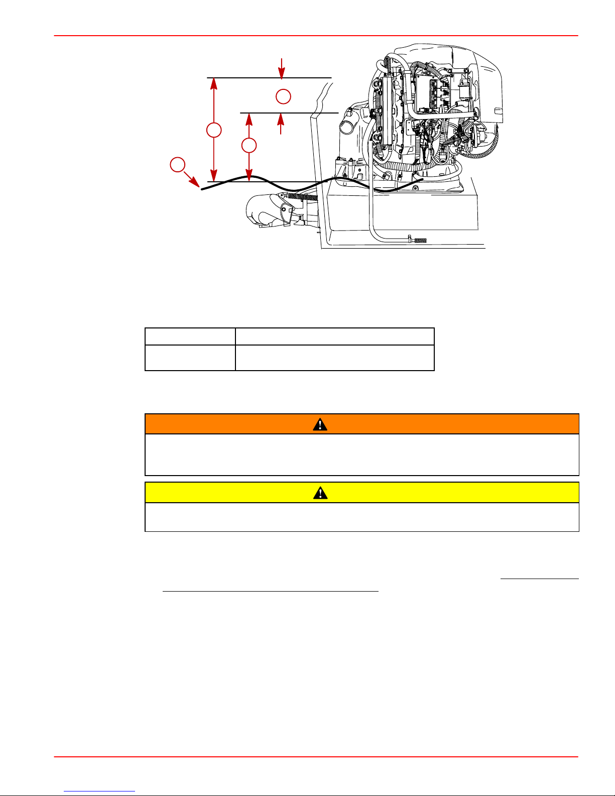
The engine must be properly located to ensure that water will not enter the engine through
the exhaust system. Determine the correct engine height by taking measurements (a) and
(b), with boat at rest in the water and maximum load aboard. Subtract (b) from (a) to find
(c). If (c) is less than specified in chart, boat construction must be altered to properly lower
waterline relative to exhaust chamber.
Page 4
90-10240040 DECEMBER 2003
Page 5
250 HP JET DRIVE INSTALLATION MANUAL
b
a
c
d
a-From Waterline to Top of Transom
b-From Highest Point on Expansion Chamber to Top of Transom
c-(a) minus (b) = (c)
d-Waterline at Rest (at Maximum Load)
59216
Model
Jet Drive (c) must be 203 mm (8 in.) or more.
Fuel Delivery System
Boating standards (NMMA, ABYC, etc.), federal standards and U. S. Coast Guard
regulations for INBOARD engines must be adhered to when installing fuel delivery
system. Failure to comply could result in severe personal injury or death.
Remove plastic plug from fuel inlet fitting. Attach fuel line to fuel fitting with U.S.
Coast Guard approved hose clamp. Inspect for fuel leaks.
1. Fuel pickup should be at least 25 mm (1 in.) from the bottom of the fuel tank to prevent
picking up impurities.
2. Fuel lines used must be U.S. Coast Guard approved (USCG type A1), fittings and lines
must not be smaller than 8mm (5/16 in.) I.D.
3. On installations requiring long lines or numerous fittings, larger size lines should be
used.
c = (a) minus (b)
WARNING
CAUTION
4. Fuel line should be installed free of stress and firmly secured to prevent vibration and/or
chafing.
5. Sharp bends in fuel line should be avoided.
6. A flexible fuel line must be used to connect fuel line to engine fuel pump to absorb deflection when engine is running.
7. A primer bulb is not necessary with this application. If a primer bulb is used, it must be
U.S. Coast Guard approved for inboard engine installations.
90-10240040 DECEMBER 2003
Page 5
Page 6

250 HP JET DRIVE INSTALLATION MANUAL
8. Vapor separator must be vented to fuel tank. Vent hose must comply with U.S. Coast
Guard/ABYC regulations.
Instrumentation
If a fused accessory panel is to be used, it is recommended that a separate circuit
(properly fused) be used from the battery to the fuse panel with sufficient wire size
to handle the intended current load.
NOTE: Check the charging capability of the engine. The electrical load of the boat should
not exceed this capacity.
We recommend the use of Mercury Precision or Quicksilver Instrumentation and Wiring
Harnesses. Refer to Mercury Precision Parts Accessories Guide for selection.
If other than Mercury Precision or Quicksilver electrical accessories are to be used, it is good
practice to use waterproof ignition components (ignition switch, lanyard stop switch, etc.).
A typical jet boat of this nature will see water splashed on these components. Therefore,
precautions must be taken to avoid ignition failure due to shorting out of ignition
components.
CAUTION
WARNING
Sudden stopping of engine (shorting ignition components) while boat is underway
will cause loss of steering control due to loss of thrust. This loss of steering control
may cause property damage, personal injury or death.
A warning horn must be incorporated in the wiring harness (see wiring diagram) to alert the
user of an overheat, low oil condition or oil pump failure.
IMPORTANT: If a warning horn system is not installed by the boat manufacturer,
Mercury Marine will not honor any warranty claims for engine damage as a result of
overheating or lack of engine oil.
Route instrumentation wiring harness back to engine, making sure that harness does not
rub or get pinched. If an extension harness is required, be sure to secure connection
properly. Fasten harnesses to boat at least every 460 mm (18 in.), using appropriate
fasteners.
Page 6
90-10240040 DECEMBER 2003
Page 7

Remote Control and Cables
The remote control must provide the following required features:
• Start in gear protection
• Neutral RPM limit at 2,000 RPM
Note: This applies to dual lever remote controls as well as single lever remote controls.
• High strength mechanism to accommodate loads transmitted to the remote control
• Shift cable travel of 76 mm 3 mm) (3 in. 1/8 in.)
• Ability to use 40 series shift cable
The remote control must meet the above criteria as well as the design criteria outlined in
the ABYC manual pertaining to Mini-Jet Boats (Standard P-23).
SHIFT CABLE
The shift cable to be used MUST MEET the following criteria:
• 40-Series Cable
• 40 Series bulkhead fitting at output end
• Allow for a minimum of 76 mm (3 iin.) of travel.
• A means of attaching and locking the cable to the shift cable bracket (provided).
250 HP JET DRIVE INSTALLATION MANUAL
• Cable end at pump must allow for a 1/4 inch clevis pin and cotter pin (all provided) to
connect cable to the reverse gate.
• Protected against water intrusion and/or corrosion as the cable end (at the pump) is sub-
mersed in water with the boat at rest.
The shift cable end (at the pump) is submersed in water. It should be sealed against water
intrusion, protected against corrosion and be able to withstand the shift loads imparted on
it by the reverse gate.
Follow shift cable adjustment procedure for proper adjustment.
THROTTLE CABLE
The throttle cable must have one end compatible with the control box. The other end must
have Mercury style connectors.
Follow throttle cable adjustment procedures for proper adjustment.
90-10240040 DECEMBER 2003
Page 7
Page 8

250 HP JET DRIVE INSTALLATION MANUAL
Steering Helm and Cable
STEERING HELM
The steering helm must limit steering cable travel to 88.9 mm ± 2.5 mm (3-1/2 in. ± 1/8 in.).
Failure to limit steering cable travel at the helm could pre-load the cable resulting
in premature failure of a steering component causing loss of steering. This loss of
steering could cause property damage, personal injury or death.
STEERING CABLE
The steering cable to be used MUST MEET the following criteria:
• 60 Series Steering Cable
• 60 Series bulkhead fitting at output end
• Allow for a minimum of 95.3 mm (3.75 in.) of travel.
• Cable end at pump must allow for a 5/16 in. threaded adaptor shouldered thru-bolt and
locknut to connect the cable to the steering arm.
• A means of attaching and locking the cable to the steering cable bracket (provided).
• Protected against water intrusion and/or corrosion as the cable end (at the pump) is sub-
mersed in water with the boat at rest.
WARNING
• The steering cable should be able to withstand the steering loads imparted on it by the
rudder.
A locking tab is provided by Mercury to be used with the steering cable having threads and
locknuts located 287 mm (11.31 in.) from cable end at pump with cable at center of travel.
Follow steering cable adjustment procedure for proper adjustment.
METHOD FOR CONTROLLING LOCATION AND SIZE
Mercury Marine recommends that the tunnel opening be done as a part of the manufacture
of the tunnel. This will ensure consistency of location as well as size.
Page 8
90-10240040 DECEMBER 2003
Page 9
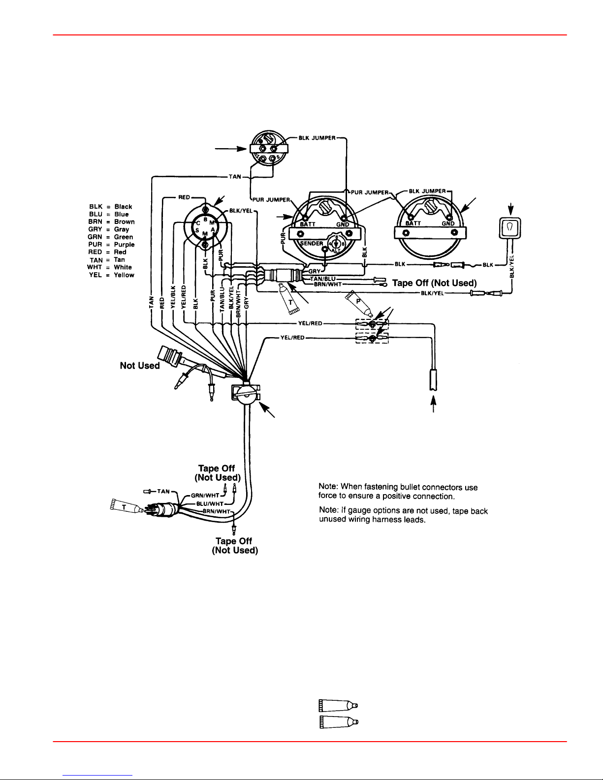
Wiring Diagram
Instrumentation, Typical Analog Installation Shown
NOTE: Refer to gauge manufacturer’s instructions for specific connections.
a
250 HP JET DRIVE INSTALLATION MANUAL
b
h
d
c
e
i
f
g
a - Temperature Gauge
b - Key Switch
c - Tachometer Gauge
d - Emergency Stop Switch
e - Tachometer Harness (P/N 84-86396A8) (Not Included
With Key/Choke Harness Kit)
f - Connect Wires Together With Screw and Hex Nut (2
Places) Apply Quicksilver Liquid Neoprene to Connections
and Slide Rubber Sleeve Over Each Connection.
g - To Neutral Start Safety Switch In Remote Control Box
h - Speedometer Gauge
i - Overheat/low oil horn
90-10240040 DECEMBER 2003
P
T
Liquid Neoprene
Dielectric Grease
Page 9
Page 10
250 HP JET DRIVE INSTALLATION MANUAL
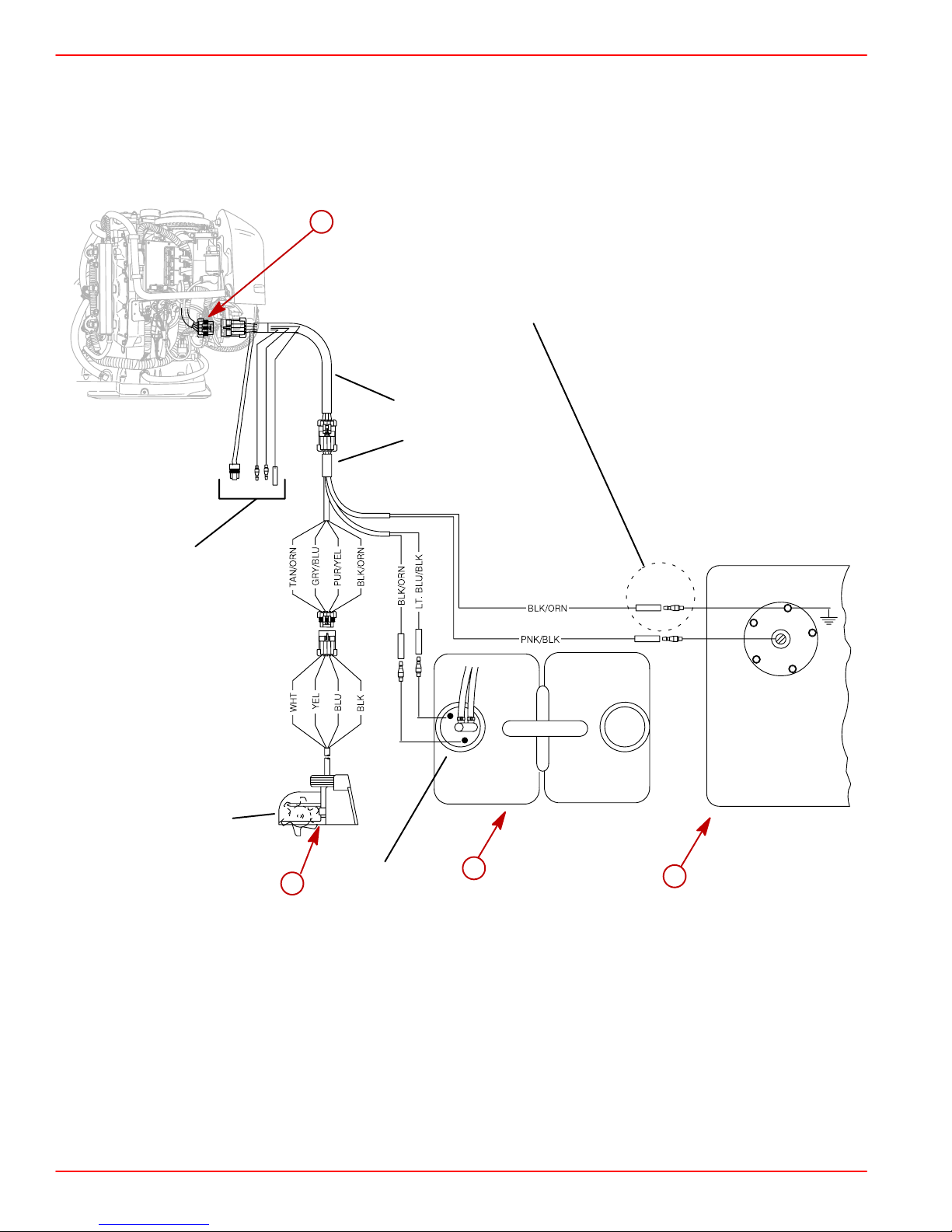
Wiring for SmartCraft Gauges
WIRING CONNECTIONS TO PADDLE WHEEL SPEED SENSOR, OIL TANK AND FUEL TANK
a
IMPORTANT: DO NOT connect the Black/Orange wire to
the fuel tank sensor when there is a engine battery ground
strap connected to the fuel tank or sender assembly. If not
used, plug the unused open bullet connector with rubber
plug P/N 13541.
84-859244A1
84-859743T2
Not Used
859223
b
Oil Tank
Sender
816190A1
c
d
a-Engine Plug
b-Paddle Wheel Speed/Outside Water Temp Sensor (If Equipped)
c-Oil Tank
d-Fuel Tank
57738
Page 10
90-10240040 DECEMBER 2003
Page 11
250 HP JET DRIVE INSTALLATION MANUAL
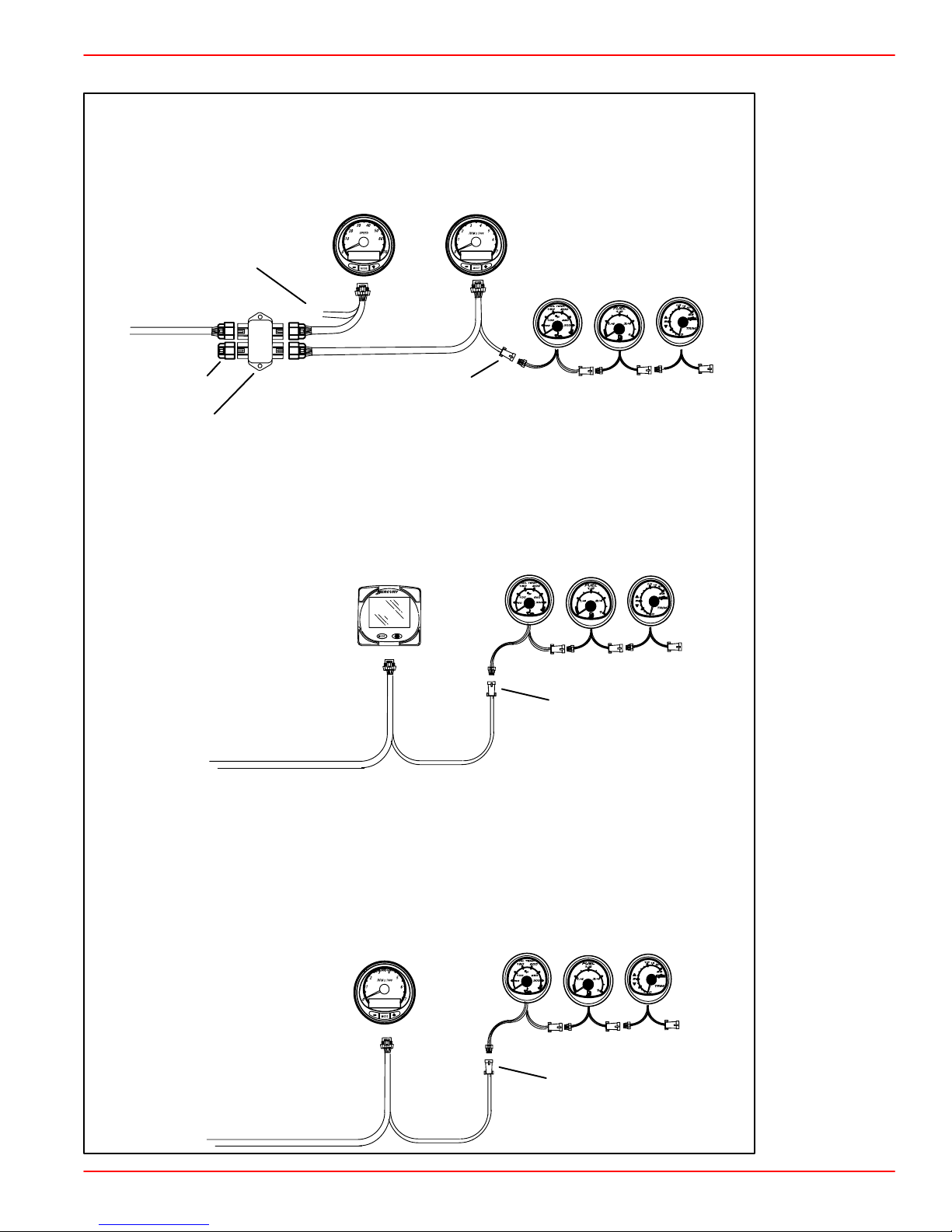
Typical System Layouts – Single Engine Product Configurations
Speedometer and Tachometer (CAN)
NOTE: CAN Type Gauges Can only be used on 2002 Model
Year and newer V-6 models that are equipped for SmartCraft
Tachometer
System Link Gauges
GPS Connection
SC Data Cable
Speedometer
+
–
Terminator
Junction Box
System Monitor (CAN)
NOTE: System Monitor can be used on 2001 model year and
newer jet drives that are equipped for SmartCraft
SC1000-2RSL System Monitor
Harness
System Link Connector
System Monitor
System Link Gauges
System Link Connector
Tachometer Only (CAN)
NOTE: CAN Type Gauges Can only be used on 2002 Model
Year and newer jet drives that are equipped for SmartCraft
SC1000-2RSL System Monitor
Harness
90-10240040 DECEMBER 2003
System Tachometer
System Link Gauges
System Link Connector
Page 11
Page 12

250 HP JET DRIVE INSTALLATION MANUAL
Wiring Information for CAN Type Gauges
REQUIREMENTS
SmartCraft communications are via the Controller Area Network (CAN), electrically implemented on a t wisted pair of wires. Note: SmartCraft harnesses include other signals besides
CAN.
The maximum distance between any two modules on the SmartCraft bus is 40 meters (130
feet). This distance is calculated as the total harness length between the modules (trunk
length plus drop lengths).
There must be exactly two termination resistors on the CAN bus.
No more than 20 modules may be connected to the bus. This is the maximum number of
connections supported by the engine control module software.
INSTALLATION GUIDELINES
SmartCraft installations should use Mercury Marine harnesses and junction boxes. This assures a robust mechanical implementation as well as proper connection of all signals.
The ideal installation uses a single trunk line with short drops to individual modules. Two
termination resistors, one at each end of the trunk line, minimize signal reflections. Signal
reflections can increase radio frequency interference and the potential for bit errors on the
bus.
The trunk line is not defined by junction boxes. The trunk should be considered to be the
distance between the termination resistors. Drops may be at the ends of the trunk line or
anywhere else that is convenient for the installation. Note that the trunk line can “loop-back”
in some installations.
• The single engine System Monitor example on page 14 illustrates a trunk line with two
drops of essentially zero length, one at the engine and the other at the gauge.
• The single engine System Tach and Speedo example on page 14 illustrates a trunk line
with one zero length drop at the engine and two three foot drops at the gauges.
Page 12
90-10240040 DECEMBER 2003
Page 13

Wiring Accessories for CAN Type Gauges
250 HP JET DRIVE INSTALLATION MANUAL
Junction Boxes
6 Way
4 Way
878492A4
* For correct placement on these terminator/resistors, refer to Wiring Installation
Guidelines preceding and Typical Installation configurations following.
* * All unused junction box ports must be covered using these weather caps.
878492A6
8 Way
878492A8
Junction Box
*
Terminator/Resistor
859318T-1
SC1000 Series (Blue Cable)
84-879968T_ Harness without Terminator/Resistor
6 Ft
10 Ft
15 Ft
20 Ft
30 Ft
84-879978T-1 System Speed Harness
3 Ft
Junction Box
**
Weather Cap
859318T-2
84-879981T_ Harness with Terminator/
Resistor on One End
10 Ft
15 Ft
20 Ft
30 Ft
84-879982T_ Harness with Terminator/
Resistor on Both Ends
20 Ft
30 Ft
SC100 Series
84-880756b_ System Link Extension
Harness
3 Ft
10 Ft
30 Ft
84-879979T-1 System Monitor and
Tachometer Harness
3 Ft
90-10240040 DECEMBER 2003
Page 13
Page 14
250 HP JET DRIVE INSTALLATION MANUAL
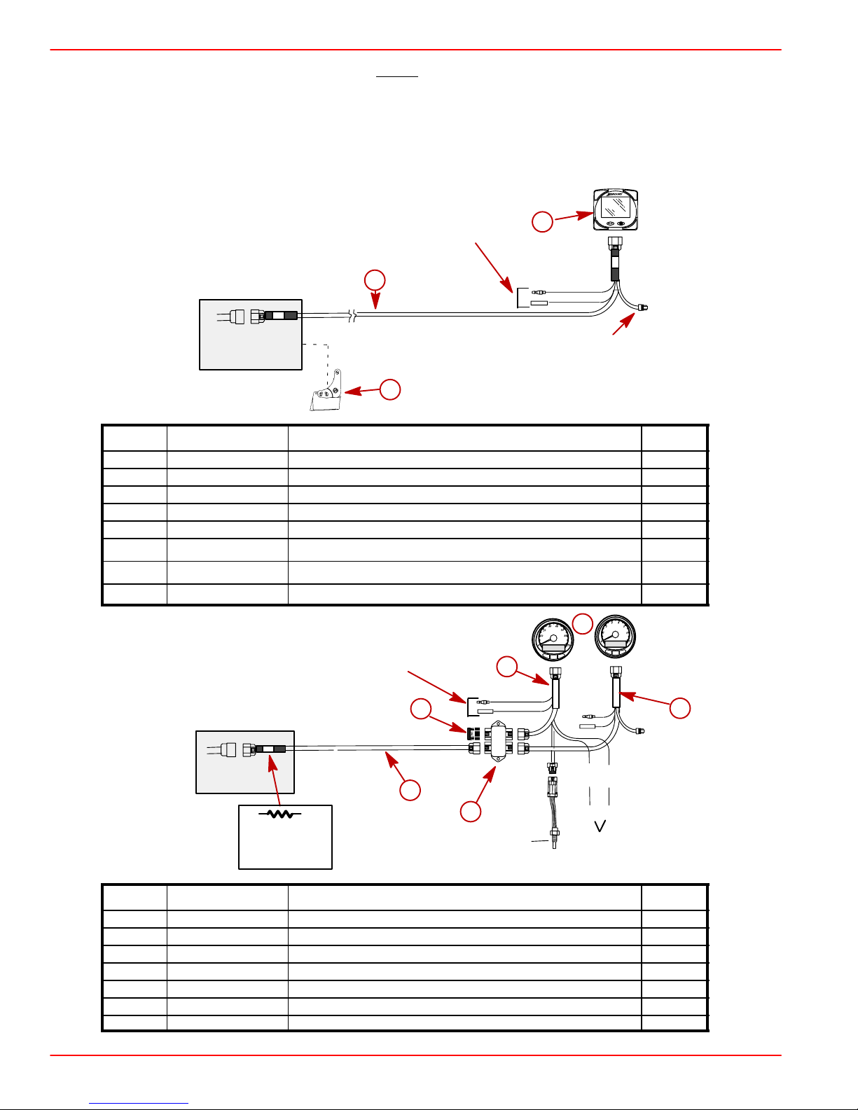
Typical Installation Configurations CAN Type Gauges
NOTE: The typical installation configurations shown on this page and the next few pages
are the lowest cost solutions. Other solutions are also possible. See Page 15 for general
guidelines.
SINGLE ENGINE APPLICATIONS
System Monitor– 2001 Model Year and Newer
Accessory Horn (816492A9) Connection
for Water Depth Warning
a
Engine
c
Ref. Part Number Description Qty.
a 879982T_ Wiring Harness SC1000-2RSL (20,30 ft) 1
b 879896K2 System Monitor – Front Mount (Outboard Only) 1
b 879896K1 System Monitor – Rear Mount (Outboard Only) 1
b 879896K4 System Monitor 2 – Front Mount (All Models) 1
b 879896K3 System Monitor 2 – Rear Mount (All Models) 1
c 881931A1 Depth Transducer – Transom Mount 1
c 881932A1 Depth Transducer – In Hull 1
c 881933A1 Depth Transducer – Through Hull 1
Optional Depth
Transducer
b
System Link
Connection
Monitor
System Tach and Speedo – 2002 Model Year and Newer
Accessory Horn (816492A9) Connection
for Water Depth Warning
b
Engine
a
c
Termination
Optional Depth Transducer is
Available
Ref. Part Number Description Qty.
a 879981T_ Wiring Harness SC1000R (10,15,20,30ft) 1
b 859318T1 Terminator/Resistor 1
c 878492T_ Junction Box (4,6,8) 1
d 879899K1 System Speedo and Tach – Single Application Kit – Gray Color 1
d 879899K11 System Speedo and Tach – Single Application Kit – White Color 1
e 879978T1 Wiring Harness SC1000-(3ft) Speed Harness 1
f 879979T1 Wiring Harness SC1000-SL-(3ft) Tach Harness 1
Resistor
On This End
Air Temp
Sensor
d
e
f
BLUE
WHITE
–+
NMEA GPS
Connection
Page 14
90-10240040 DECEMBER 2003
Page 15

Mercury Jet Drive Hull Dimensions
HULL OPENING
The pump to powerhead opening in the hull is the most important factor to consider in a Jet
Drive installation. There are three areas of concern:
1. Location (a) of the pump to powerhead hull opening relative to the boat bottom for proper
ride plate seal fit.
2. Dimensional control of the opening - corner radii (b), straightness (c) and size (d) for
proper grommet installation, and corner radii (e) for ride plate seal fit.
3. Flatness and thickness of the area around the hull opening for proper grommet sealing
(see drawing on next page).
4. The hull opening must have a 0.125 in. radius on both the top and bottom corners all
around the opening.
Tunnel Dimensions (in inches)
250 HP JET DRIVE INSTALLATION MANUAL
1 1/16 +/– 1/16
12 1/8 +/– 1/16
2 9/16 +/– 1/16
a
a - Location
b - Corner Radii
c and d - Size and Straightness
e - Corner Radii for Ride Plate
e
c
7 1/16 +/– 1/16
b
3/4 +/– 1/16
14 11/16 +/– 1/16
d
14 5/16 +/– 1/16
16 1/4 +/– 1/16
c
d
4.07 .06
a
3 13/16 +/– 1/16
3 5/8 +/– 1/16
a
a
28249
90-10240040 DECEMBER 2003
Page 15
Page 16

250 HP JET DRIVE INSTALLATION MANUAL
Installing Jet Pump
The hull opening dimensions are critical for proper sealing between Jet Pump and
boat. Measure cutout thickness and overall dimensions before attempting a Jet
Pump installation.
1. Install tunne l g r ommet in cut-out of boat by gluing front portion of grommet to tunnel with
Loctite 454 or equivalent. Avoid gluing flexible sealing lips to tunnel.
NOTE: The procedure for gluing the grommet is not required for the following grommets:
Part Number 820663-250 (1/4 in grommet)
Part Number 820663-375 (3/8 in grommet)
Part Number 882811 (3/8 in grommet)
a
CAUTION
a
CUTOUT THICKNESS
.375”
+0.050
–0.030
Use Grommet P/N:
25-877789
a-Glue Front Portion of Grommet
b-Avoid Gluing Flexible Sealing Lips to Tunnel
c-Loctite 454
b
c
b
Page 16
90-10240040 DECEMBER 2003
Page 17

250 HP JET DRIVE INSTALLATION MANUAL
2. Install thru-hull fittings and bellows assemblies. Tighten securely after pump is secured
in hull.
a
e
c
d
c
b
a-Thru-Hull Fitting, and Bellows Assembly
b-Thru-Hull Fitting and Nut
c-Clamp
d-Bellows
e-Slit Adaptor
3. Route steering cable through the thru-hull fitting and bellows. Route cable t hrough the port
side flange of pump housing. Install nut on cable before routing cable through wear ring.
a
b
58142
a-Shift Cable
b-Wear Ring
4. Install tab washer and nut on cable after guiding through wear ring. Locate tab washer
in tab hole. Coarse cable adjustment is made using these nuts. Do not tighten until after
final steering adjustment is made.
a-Tab Hole
b-Nut
c-Tab Washer
d-6.4 mm (0.25 in.)
90-10240040 DECEMBER 2003
a
d
b
c
58143
Page 17
Page 18

250 HP JET DRIVE INSTALLATION MANUAL
5. Route shift cable through the thru-hull fitting and bellows. Route cable through the starboard side hole in flange of pump housing.
a-Shift Cable
IMPORTANT: Ensure that the shift lever in the control box is set for 76 mm (3 in.) of
travel.
NOTE: It is easier to adjust the shift and steering cables before installing pump unit in boat.
a
58144
6. Spray soapy water on inside surface of tunnel grommet and ride plate seal.
a
b
a-Tunnel Grommet
b-Ride Plate Seal
NOTE: When installing pump in tunnel, be sure cables are below tunnel grommet flange on
pump to prevent pinching of cables between pump and boat.
Page 18
90-10240040 DECEMBER 2003
Page 19

250 HP JET DRIVE INSTALLATION MANUAL
7. Install jet pump by pushing unit through opening in tunnel grommet. Ride plate seal
should fit snug in boat tunnel without any gaps along perimeter.
a
b
a-Jet Pump
b-Tunnel Grommet
8. Install gasket and O-ring seal on jet pump.
a
b
a-Gasket
b-O-Ring Seal
9. Install cover on jet pump and secure with ten locknuts. Torque to 47 Nm (35 lb ft).
NOTE: Before torquing nuts, check ride plate seal for proper fit in tunnel.
a
59292
b
a-Locknuts (10) – Torque to 47 Nm (35 lb ft)
b-Fitting for Flush Hose (Hose can be connected at this time. Refer to installation
of Flushing Kit instructions following)
10. Check steering and shift cables for freedom of movement. Correct installation if cables
are pinched.
90-10240040 DECEMBER 2003
Page 19
Page 20

250 HP JET DRIVE INSTALLATION MANUAL
Steering Cable Adjustment
1. Slide bellows assembly over cable and thread on cable completely. Do not tighten.
a
54456
a-Bellows
2. Thread cable end adaptor on steering cable 14 turns (to allow for adjustment).
a
54902
a-Cable End Adaptor
Page 20
90-10240040 DECEMBER 2003
Page 21

250 HP JET DRIVE INSTALLATION MANUAL
3. Center rudder assembly on nozzle.
4. Center steering wheel by turning wheel lock to lock and positioning wheel midway
between locks.
5. Adjust cable end adaptor until thru-hole in adaptor lines up with threaded hole in steering
arm. This is the steering cable fine adjustment. Cable end adaptor MUST be installed
on steering cable a minimum of nine (9) turns.
WARNING
Cable end adaptor must be installed a minimum of nine (9) turns. Failure to install
cable end adaptor on steering cable a minimum of nine (9) turns could result in loss
of steering control of boat, personal injury, or death.
6. Attach steering cable to steering arm with bolt, washer and locknut. Torque nut to 7.9
Nm (70 lb in).
c
e
d
a
b
f
54902
a-Bellows Nut
b-Steering Arm
c-Bolt
d-locknut
e-Flat Washer
f-Cable Nuts
7. Tighten cable nuts.
8. Check steering adjustment to ensure that the helm limits cable travel for maximum left
and right turns. Correct if required.
9. Secure cable nut with tab washer by bending a tab over flat of hex nut.
90-10240040 DECEMBER 2003
Page 21
Page 22

250 HP JET DRIVE INSTALLATION MANUAL
10. Apply perfect seal to end threads.
19
19
Perfect Seal
11. Turn bellows nut out and tighten against cable end adaptor.
a
b
54908
a-Bellows Clamp
b-Bellows Nut Tight Against Jam Nut
12. Turn rudder to port to compress bellows as much as possible. Push bellows over cable
conduit and secure with bellows clamp.
13. Secure bellow s t o t hru-hull fitting with clamp. Slide slit adaptor over cable and push into
bellows. Secure with clamp.
Page 22
a
b
c
d
a-Steering Cable, Thru-Hull Fitting, and Bellows Assembly
b-Thru-Hull Fitting and Nut
c-Clamp
d-Bellows
e-Slit Adaptor
NOTE: Check for proper placement of slit adaptor around cable. Placement of wrong slit
adaptor may result in leak.
e
c
90-10240040 DECEMBER 2003
Page 23

Shift Cable Adjustment
IMPORTANT: The shift cable MUST BE properly adjusted. The shift cable is adjusted
so that the reverse gate is not pre-loaded against either the forward or reverse stop.
Pre-load in either position may cause failure of the stop and/or premature wear of the
shift cable or control box components. It may also cause stiffness of the throttle
control.
1. Thread the cable barrel onto the shift cable.
250 HP JET DRIVE INSTALLATION MANUAL
a
a-Cable Barrel
2. Use a de-greaser and clean off all oil film from the area on the shift cable shown.
NOTE: Removing the oil film from the shift cable is necessary to prevent the bellows from
sliding on the cable.
a
a-Remove Oil Film From This Area
3. Slide the b e l l ows over the shift cable end. Position and install the bellows onto the cable
conduit as shown. Fasten ends with clamp and cable tie.
c
b
a
25.4 mm (1 in.)
a-Bellows
b-Clamp
c-Cable Tie
90-10240040 DECEMBER 2003
Page 23
Page 24

250 HP JET DRIVE INSTALLATION MANUAL
4. Loosen the locknuts and unfasten the top end of the shift cable retainer.
NOTE: Locknuts do not have to be removed to open shift cable retainer. Loosen top nut 1
turn and loosen bottom nut until retainer
a-Shift Cable Retainer
b-Plastic Barrel Holder
5. Install shift cable end in slot of the reverse gate and secure with clevis pin, flat washer,
and cotter pin. Bend over ends of cotter pin.
b
a
c
b
a
a-Clevis Pin
b-Flat Washer
c-Cotter Pin
WARNING
The shift cable must be adjusted correctly so that the reverse gate does not interfere with water flow coming out of the rudder. If the reverse gate hangs down into
the water flow, a vibration may be felt in the control box. If this occurs, reduce
throttle immediately and readjust the cable. Improper adjustment may result in
pump damage including loss of the reverse gate. Failure to properly adjust the shift
cable could result in loss of neutral and reverse, property damage, personal injury
or death.
Page 24
90-10240040 DECEMBER 2003
Page 25

250 HP JET DRIVE INSTALLATION MANUAL
6. Adjust shift cable as follows:
a. Position the control box into forward position.
b. Position the reverse gate against the forward stop. With the reverse gate at this
position, adjust the cable barrel to fit into the barrel holder with slight tension of the
reverse gate against the stop.
c. After adjusting the shift cable, secure the cable barrel in place with the shift cable
retainer. Fasten the retainer by tightening both locknuts.
IMPORT ANT: The shift cable retainer must be fastened with self-locking nylon insert
locknuts. These locknuts must never be replaced with common nuts (non-locking)
as they could vibrate off, freeing the shift cable to disengage.
WARNING
Disengagement of the shift cable can result in the boat suddenly shifting into
reverse. This unexpected action could cause occupants to be thrown forward in the
boat or to be ejected overboard. Serious injury or death could result.
a
c
b
e
d
a-Reverse Gate
b-Forward Stop
c-Cable Barrel
d-Locknuts
e-Shift Cable Retainer
7. Adjust the reverse stop (located on starboard side of the nozzle) so that the stop just
touches the reverse gate with the control handle in reverse position. Torque reverse stop
screw to 14 Nm (120 lb in.).
8. Check shift cable/reverse gate adjustment as follows:
a. Shift the control box a few times from the forward position to reverse position.
b. Return the control handle back to forward. Pull back on the reverse gate gently to
take slack out of the cable. Check for the 9.5 to 12.7 mm (3/8 to 1/2 in.) clearance
space between the reverse gate and rudder. If necessary, readjust the cable barrel.
90-10240040 DECEMBER 2003
Page 25
Page 26

250 HP JET DRIVE INSTALLATION MANUAL
9. Secure bello w s t o t h r u - h ull fitting with clamp. Slide slit adaptor over cable and push into
bellows. Secure with clamp.
a
e
c
d
c
b
a-Shift Cable, Thru-Hull Fitting, and Bellows Assembly
b-Thru-Hull Fitting and Nut
c-Clamp
d-Bellows
e-Slit Adaptor
NOTE: Check for proper placement of slit adaptor around cable. Placement of wrong slit
adaptor may result in leak.
Page 26
90-10240040 DECEMBER 2003
Page 27

Installing Powerhead
1. Install gasket on drive housing cover.
2. Install water inlet O-ring and driveshaft opening O-ring.
3. Lubricate drive shaft splines with Special Lubricant 101.
250 HP JET DRIVE INSTALLATION MANUAL
a
b
c
d
a-Gasket
b-Water Inlet O-Ring
c-Drive Shaft Opening O-Ring
d-Lubricate driveshaft splines with Special Lubricant 101
4. Lower powerhead on drive housing cover. Align driveshaft splines with crankshaft.
5. Follow the torque sequence shown and first torque locknuts to 27 Nm (20 lb ft) then
repeat torque sequence, torquing locknuts to 47 Nm (35 lb ft).
a
a-Locknut (12) – Torque to 45 Nm (35 lb ft)
90-10240040 DECEMBER 2003
12
8
7
3
4
2
5
1
6
9
11
10
Page 27
Page 28

250 HP JET DRIVE INSTALLATION MANUAL
Fuel Line and Fuel Vapor Vent Hose Connections
1. Connect fuel l i n e t o f u e l i n l e t fitting, secure with U.S. Coast Guard approved hose clamp
(183.532).
2. Vapor separator tank (VST) must be vented to fuel tank. Vent hose must comply with
U.S. Coast Guard/ABYC regulations.
b
a
c
a-Fuel Line – Secure Connection with U.S. Coast Guard Approved Hose clamp
b-Vent Hose
c-Vapor Separator Tank (VST)
Page 28
90-10240040 DECEMBER 2003
Page 29

250 HP JET DRIVE INSTALLATION MANUAL
Battery Cables and Remote Wiring Harness Connections
WARNING
U.S. Coast Guard regulation #33 CFR 183.445 requires that the positive battery
cable connection at the starter solenoid terminal be protected by either a boot or
protective shield.
NOTE: Engine electrical system is negative (–) ground.
1. Slide the protector boot (provided) onto the positive (+) battery cable.
b
a
a-Positive Battery Cable
b-Protector Boot
2. Fasten the positive (+) battery cable to the starter solenoid (+) terminal. Seal connection
with Liquid Neoprene. Push the protector boot over the connection.
3. Fasten the negative (–) battery cable to engine grounding bolt located on the engine
block below the starter motor. Seal connection with Liquid Neoprene.
4. Connect battery cables to battery. Make sure that all battery terminal connections are
tight; then, spray terminals with a battery connection sealant to help prevent corrosion.
5. Attach the remote wiring harness to the engine plug. Place harness plug into holder.
b
c
a-Positive Battery Cable Attaching Location – Push the Protector Boot over the
Connection
b-Negative Battery Cable Attaching Location (Engine Ground)
c-Remote Wiring Harness Connection – Place Connection into Holder
90-10240040 DECEMBER 2003
a
Page 29
Page 30

250 HP JET DRIVE INSTALLATION MANUAL
Throttle Cable Installation
1. Position remote control into neutral.
2. Attach throttle cable to the throttle lever. Secure with washer and locknut.
a-Nylon Washer
b-Locknut – Tighten locknut then back off locknut 1/4 turn
3. Adjust the cable barrel so that the installed throttle cable will hold the idle stop screw
against the stop.
a
b
b
a
a-Cable Barrel – Adjust To Hold Idle Stop Screw Against Stop
b-Idle Stop Screw
4. Check throttle cable adjustment as follows:
a. Move throttle from idle to wide open several times to activate throttle linkage.
b. Return throttle to neutral. Place a thin piece of paper between idle adjustment screw
and idle stop. Adjustment is correct when the paper can be removed without tearing,
but has some drag on it. Readjust cable barrel if necessary.
IMPORTANT: The idle stop screw must be touching the stop.
b
a
a-Idle Stop Screw
b-Idle Stop
5. Lock the barrel holder in place with the cable latch.
Page 30
90-10240040 DECEMBER 2003
Page 31

Oil Injection Set-Up
1. Mount the oil reservoir in a suitable location. Use the oil tank hold down kit provided.
2. Oil hoses must be arranged so they cannot become pinched, kinked, sharply bent or
stretched during operation of the engine.
3. Remove shipping cap from oil filter and connect oil hose (with blue stripe) to filter with
cable tie.
250 HP JET DRIVE INSTALLATION MANUAL
a
b
a-Oil Hose (with Blue Stripe)
b-Oil Filter
4. Remove shipping cap from fitting and connect oil hose (without blue stripe) to fitting with
cable tie.
a
a-Oil Hose (without Blue Stripe)
90-10240040 DECEMBER 2003
Page 31
Page 32

250 HP JET DRIVE INSTALLATION MANUAL
5. Fill remote oil tank with the recommended oil listed in the Operation and Maintenance
Manual. Tighten fill cap.
6. Remove cap and fill engine oil tank with oil. Reinstall the fill cap.
a
a-Engine Oil Tank
7. All Mercury Jet Drive powerheads have the oil systems primed. To determine if repriming is necessary, check the clear oil line between the engine oil reservoir and the oil
pump. If there are no air bubbles in the line, it is not necessary to reprime the oil system.
If air bubbles are present, it will be necessary to reprime the system using the Digital
Diagnostic Terminal (DDT). This method fills the oil pump, oil supply hose feeding pump,
and oil hoses going to the vapor separator. Refer to procedure in the Technician Reference Manual provided with the Digital Diagnostic Software Cartridge Part. No.
91-880118.
8. Loosen the fill cap on the engine oil tank.
9. Start the engine. Run the engine until all the air has been vented out of the tank and oil
starts to flow out of the tank. Re-tighten fill cap.
a
a-Engine Oil Tank
Page 32
90-10240040 DECEMBER 2003
Page 33

Bilge Siphon Feature
The Jet Drive incorporates an automatic bilge siphoning feature. The bilge siphon is working
whenever the engine is running above idle speeds. Maximum performance of the bilge
siphon is realized above 3,000 RPM. A hose is attached to the jet pump nozzle. The hose
is routed to the engine compartment and placed in the bilge. Water exiting the nozzle creates
a suction or vacuum in the hose creating the bilge siphon, drawing water out of the boat.
Installing Bilge Siphon
The siphon break must be located above the water line at the highest point. The siphon
break has a 0.020 in. hole which must be kept open.
1. Uncoil the siphon hose. Place the pick up screen in the bilge.
2. Place the siphon break (located in the siphon hose) above the water line at the highest
point. Fasten hose with cable tie so that the siphon break will stay at the highest point.
250 HP JET DRIVE INSTALLATION MANUAL
a
b
59210
c
a-Siphon Break
b-Cable Tie
c-Pick Up Screen
WARNING
Failure to locate siphon break above the water line and keep hole open could result
in water entering the bilge through the siphon system causing property damage,
personal injury or death.
59216
90-10240040 DECEMBER 2003
Page 33
Page 34

250 HP JET DRIVE INSTALLATION MANUAL
Water By-Pass System
The water by-pass system is designed to improve powerhead cooling at idle speed.
1. Locate the water by-pass components (provided).
a
c
b
a-Thru-Hull Fitting
b-Brass Nut
IMPORTANT: The thru-hull fitting must be correctly positioned in the boat transom
as instructed in Step 3.
2. Select the mounting location for the thru-hull fitting as follows:
2 in. (50 mm)
Minimum
Back View
of Transom
A
Top View of
Transom
A
• The thru-hull fitting must be mounted in either side of the transom within the zones
marked A.
c-Hose Clamp
Water Line
• The thru-hull fitting must be located a Minimum of 50 mm (2 in.)
above the water line
when boat is at its maximum load capacity.
• The water by-pass hose must slope down towards the thru-hull fitting at a minimum rate
of 25 mm (1 in.) drop per 300 mm (12 in.) of hose.
• The thru-hull fitting should be positioned so the water spray will be pointed downward.
3. After the location has been selected for the thru-hull fitting, drill a 14.3 (9/16 in.) diameter.
hole.
4. Apply Marine Sealer to entire length of threads and under the head of the thru-hull fitting.
Fasten the fitting into the transom with the brass nut (provided).
c
b
a
a-Thru-Hull Fitting
b-Brass Nut
c-Marine Sealer
Page 34
90-10240040 DECEMBER 2003
Page 35

250 HP JET DRIVE INSTALLATION MANUAL
5. Connect a water by-pass hose between engine fitting and thru-hull fitting. Secure con-
nections with hose clamps.
NOTE: Make sure the hose slopes at a minimum rate of 25 mm (1 in.) drop per 300 mm
(12 in.) of hose.
a-Water By-Pass Hose – Secure Connections with Hose Clamps
a
90-10240040 DECEMBER 2003
Page 35
Page 36

250 HP JET DRIVE INSTALLATION MANUAL
Installation of Flushing Kit
1. Attach flush hose to fitting in drive housing cover. Secure with hose clamp.
IMPORTANT: Failure to secure flush hose to fittings, will allow water to fill boat.
b
a
a-Flush Hose
b-Hose Clamp
2. Attach flush hose to flush adapter. Secure with clamp as shown.
a
b
a-Flush Hose
b-Flush Adaptor
c-Hose Clamp
c
Page 36
90-10240040 DECEMBER 2003
Page 37

250 HP JET DRIVE INSTALLATION MANUAL
CAUTION
BEFORE mounting flush adapter bracket, route flush adapter and hose to selected
mounting location. Hose routing MUST NOT INTERFERE with throttle and/or control linkage.
NOTE: Mount flush adapter bracket in an area of the motor compartment that has a mount-
ing surface that is thicker than the depth of the mounting screws.
3. Locate area (easily accessible) within motor compartment to mount flush adapter
holder. Secure with screws supplied.
b
a
a-Flush Adaptor Holder
b-Screw (3)
4. Snap flush adapter into holder as shown.
a-Flush Adaptor
a
90-10240040 DECEMBER 2003
Page 37
Page 38

250 HP JET DRIVE INSTALLATION MANUAL
Flushing Instructions
DO NOT run engine on flushing kit above idle speeds. Damage to engine from overheating, due to lack of water supply may occur.
1. With engine off, remove flush adapter plug and attach water hose.
WARNING
b
a-Flush Adapter
b-Water Hose
IMPORTANT: Do not run engine above idle when flushing.
2. Turn water a ll t he w ay o n. S tart t he e ngine a nd f lush t he e ngine b lock f or a t l east 1 0 m inutes.
a
52121
NOTE: An insufficient flow of water to the engine may cause the engine to overheat. If the
warning horn sounds, immediately stop engine and allow to cool.
3. Stop the engine. Turn off the water and remove water hose from flush adapter and reinstall the cap. Tighten cap securely.
4. Flush outer surfaces of water outlet nozzle.
Suggested Flushing Intervals
• After running jet in salt water environment
• Where boat was operated in shallow water or run aground
• Overheat warning horn sounds (May be caused from accumulation of particles/debris
in jet powerhead)
If any of the above conditions are not corrected with normal flushing of engine, it
is recommended that the jet be taken to your authorized dealer for service.
Page 38
CAUTION
90-10240040 DECEMBER 2003
Page 39

Trim Plate Adjustment
The Jet Drive unit trim plate is factory set for general applications. Should a particular boat
experience porpoising problems, the trim plate can be adjusted as follows:
1. Loosen both jam nuts on trim plate (one starboard and one port).
2. Turn both screws the exact same number of turns. Tighten both jam nuts against trim
plate. The distance from top of nut to bottom of boss should be equal on both sides.
a
250 HP JET DRIVE INSTALLATION MANUAL
b
c
d
e
f
a-Jam Nut with Washer (Two: One On Each Side)
b-Jam Nut
c-Small Diameter Washer
d-Large Diameter Washer
e-Plate
f-Screw
WARNING
Adjusting the trim plate may affect boat handling (steering). Overly sensitive
steering or reduced turning ability could result from trim plate adjustments. Boat
handling characteristics also vary with the load distribution in the boat. Use caution
after adjusting: check for acceptable handling characteristics under all loading
conditions. Failure to adequately test the boat could result in inadequate steering
control resulting in property damage, personal injury or death.
90-10240040 DECEMBER 2003
Page 39
Page 40

250 HP JET DRIVE INSTALLATION MANUAL
Exhaust System Installation
General Exhaust System Notes
1. Exhaust system application must meet ABYC standard P-1 for marine exhaust
installations.
2. The entire exhaust system must meet 1309.99 kPa (190 p.s.i.) (1309.99 burst pressure.
3. All rubberized exhaust system components must meet SAE J-2006 standards for
marine exhaust hoses.
Mufflers must be secured in such a way as to prevent muffler movement during inadvertent engine backfire. Movement of mufflers may result in exhaust hose loosening which could cause boat sinking due to water intrusion.
4. The mufflers and exhaust hoses must be adequately supported for proper orientation
and to prevent overstressing the exhaust components. The support requirements will
vary with exhaust system design and the amount of G-forces to be encountered.
5. Rubber hose should be connected to pipes with flares or beads or barbs to prevent the
hose from sliding off the pipe under pressure.
CAUTION
6. For additional exhaust system recommendations, see MERCURY spec. 90-884386
which covers all jet drive exhaust applications not covered under these guidelines.
Exhaust Outlet Measurement Procedure
1. Fill all fuel, oil and water tanks to maximum capacity.
2. Add maximum allowable cargo weight to boat in areas where it will be stored.
3. Add 86 kg (190 lbs) of weight in all locations where each passenger will sit during normal
operation.
4. Using diagrams provided (following), measure to ensure location of muffler outlets.
5. Move load weight and cargo weight to stern of boat to simulate greatest stern down attitude the boat will encounter such as when loading.
6. Recheck muffler outlet measurements.
7. Check exhaust system slope to ensure 5° down hill slope.
Page 40
90-10240040 DECEMBER 2003
Page 41

Top View
250 HP JET DRIVE INSTALLATION MANUAL
d
a
b
a-250 hp – 878147-A1 Muffler Assembly, Port [22.8 cm (9.0 in.)] with
7.6 cm (3.0 in.) Outlet
b-Connection Piping between Expansion Chamber and Muffler must be made of
7.6 cm (3.0 in.) O.D. Tubing. Tubing must be either 5052 or 6061 (14 ga) aluminum or type 304 (14 ga) stainless steel to protect against corrosion.
c-57885-A1 Flange Assembly (2 required) or equivalent through transom fittings
may extend 12.7 cm (5 in.) below water line for quiet idle operation. Exhausting
under a swim platform or other horizontal surface may cause transmission of
noise and vibration to the boat during operation.
d-250 hp – 878148-A1 Muffler Assembly, Starboard [22.8 cm (9.0 in.)] with
7.6 cm (3.0 in.) Outlet.
c
90-10240040 DECEMBER 2003
Page 41
Page 42

250 HP JET DRIVE INSTALLATION MANUAL
Aft View
a
b
c
d
n
g
e
f
h
i
m
j
k l
a-Alternate Installation – If rubber hosing is to be used for connection between
the expansion chamber and the muffler, a inner sleeve made of 6061-T6, 14 ga.
aluminum tubing must be used as a liner and secured with 2 stainless steel
hose clamps p/n 54-815504 or equivalent. Sleeve should be flared to fit up to
the expansion chamber outlet so as to protect this region from exhaust gas.
b-Typical Recommended Installation – 54-815504 256 stainless steel clamp or
equivalent. All exhaust hoses and/or tubes must be secured with 2 clamps at
each connection.
c-Mufflers may be mounted using straight piping.
d-25° outlet angle of expansion chamber.
e-15.2 cm (6.0 in.) minimum.
f-Reference maximum practical.
g-25° maximum from horizontal.
h-Optional exhaust outlet cover.
i-5.1 cm (2.0 in.) minimum.
j-10 2 cm (4.0 in.)
k-To minimize the back flow of exhaust gases into the cockpit or interior of boat,
the exhaust termination should be located as far outboard of the centerline as
practical.
l-Final system installation shall be reviewed by a MERCURY Field Representative
using a modified expansion chamber to ensure back pressure does not exceed
10.3 kg (1.8 psi) at 304.8 cm (1000 ft) above sea level or less. This test needs to
be performed with the boat in the water and under way. No special loading of the
boat is required. However, the engine must be capable of reaching the specified
W.O.T. engine speed. Maximum RPM must be verified using an accurate service
tachometer.
m-Exhaust system components should be rubber mounted, independently sup-
ported and restrained to minimize noise transmission to the boat and stress on
exhaust system components.
n-10° minimum angle from expansion chamber outlet to muffler inlet.
Page 42
90-10240040 DECEMBER 2003
Page 43

Side View
b
250 HP JET DRIVE INSTALLATION MANUAL
d
a
e
f
c
a-This line represents the bottom edge of the muffler outlet tube. Measure to en-
sure that the lowest possible location of the bottom edge of the muffler tubes
never gets within 5.1 cm (2.0 in.) of the maximum depth waterline.
b-5.1 cm (2.0 in.). When installing muffler assemblies, a 5.1 cm (2.0 in) minimum
distance between bottom of muffler and water line must be kept. This minimum
distance must be calculated with boat under its maximum load. Tilt muffler assemblies back towards outlet to ensure self draining.
c-Water Line
d-Covers may be placed over exhaust outlets to reduce exhaust noise and may
extend 10 cm (5 in.) or less below waterline when boat is at rest.
e-5.1 cm (2.0 in.)
f-5° outlet angle.
90-10240040 DECEMBER 2003
Page 43
Page 44

250 HP JET DRIVE INSTALLATION MANUAL
Side View of Expansion Chamber Outlet Pipe and Exhaust Pipe Connection
a
a-A spacer must be used with all 7.6 cm (3.0 in.) tube applications. A spacer
having a 6.73 cm (2.65 in.) I.D. and a 7.6 cm (3.0 in.) O.D. needs to be installed
over the expansion chamber outlets.
Page 44
90-10240040 DECEMBER 2003
Page 45

Pre-delivery Inspection
Not Check/
Applicable Adjust CHECK BEFORE RUNNING
250 HP JET DRIVE INSTALLATION MANUAL
❏❏Water hose connection/torqued
❏❏Cover plate & adaptor plate
fasteners torqued
❏❏Battery meets engine
specification
❏❏Battery charged & secure
❏❏All electrical connections tight
❏❏All fuel connections tight
❏❏Throttle, shift, & steering adjusted
correctly and fasteners torqued
❏❏Shift cable adjusted to keep
reverse gate above rudder in
forward w/ slack pulled
out of cable and against the stop.
❏❏Pump housing oil level full
(See Owner’s Manual)
❏❏Idle:____________RPM
❏❏Forward-Neutral-Reverse
operational
❏❏Steering operational throughout
entire range
❏❏Acceleration test
❏❏WOT:___________RPM
❏❏Boat handling
POST WATER CHECK
❏❏Re-torque adapter plate fasteners
❏❏No fuel, oil, water or exhaust
leaks
❏❏Re-check shift cable adjustment.
Readjust as necessary
❏❏Oil injection reservoir full and bled
❏❏Warning system operational
ON THE WATER CHECK
❏❏Starter neutral safety switch
operational
❏❏Lanyard stop switch operational
❏❏All gauges read properly
❏❏No fuel or oil leaks
❏❏No water leaks
❏❏No exhaust leaks
90-10240040 DECEMBER 2003
Page 45
Page 46

 Loading...