

Page 1

Operation
and
Maintenance
Manual
© 2016 Mercury Marine
200–350 (Including Pro Series) Verado FourStroke
8M0125708 1216 eng
Page 2

eng
Page 3

Welcome
You have selected one of the finest marine power packages available. It
incorporates numerous design features to ensure operating ease and durability.
With proper care and maintenance, you will enjoy using this product for many
boating seasons. To ensure maximum performance and carefree use, we ask
that you thoroughly read this manual.
The Operation and Maintenance Manual contains specific instructions for using
and maintaining your product. We suggest that this manual remain with the
product for ready reference whenever you are on the water.
Thank you for purchasing one of our products. We sincerely hope your boating
will be pleasant!
Mercury Marine, Fond du Lac, Wisconsin, U.S.A.
Name / function:
John Pfeifer, President,
Mercury Marine
Read This Manual Thoroughly
IMPORTANT: If you do not understand any portion of this manual, contact your
dealer. Your dealer can also provide a demonstration of actual starting and
operating procedures.
Notice
Throughout this publication, and on your power package, warnings, cautions,
and notices, accompanied by the International Hazard Symbol
!
, may be
used to alert the installer and user to special instructions concerning a
particular service or operation that may be hazardous if performed incorrectly
or carelessly. Observe them carefully.
These safety alerts alone cannot eliminate the hazards that they signal. Strict
compliance with these special instructions while performing the service, plus
common sense operation, are major accident prevention measures.
!
WARNING
Indicates a hazardous situation which, if not avoided, could result in death or
serious injury.
!
CAUTION
Indicates a hazardous situation which, if not avoided, could result in minor or
moderate injury.
eng i
Page 4

NOTICE
Indicates a situation which, if not avoided, could result in engine or major
component failure.
IMPORTANT: Identifies information essential to the successful completion of
the task.
NOTE: Indicates information that helps in the understanding of a particular step
or action.
IMPORTANT: The operator (driver) is responsible for the correct and safe
operation of the boat, the equipment aboard, and the safety of all occupants
aboard. We strongly recommend that the operator read this Operation and
Maintenance Manual and thoroughly understand the operational instructions for
the power package and all related accessories before the boat is used.
!
WARNING
The engine exhaust from this product contains chemicals known to the state
of California to cause cancer, birth defects or other reproductive harm.
The serial numbers are the manufacturer’s keys to numerous engineering
details that apply to your Mercury Marine power package. When contacting
Mercury Marine about service, always specify model and serial numbers.
Descriptions and specifications contained herein were in effect at the time this
was approved for printing. Mercury Marine, whose policies are based on
continuous improvement, reserves the right to discontinue models at any time
or to change specifications or designs without notice and without incurring
obligation.
Warranty Message
The product you have purchased comes with a limited warranty from Mercury
Marine; the terms of the warranty are set forth in the Warranty Manual included
with the product. The Warranty Manual contains a description of what is
covered, what is not covered, the duration of coverage, how to best obtain
warranty coverage, important disclaimers and limitations of damages, and
other related information. Please review this important information.
Copyright and Trademark Information
© MERCURY MARINE. All rights reserved. Reproduction in whole or in
part without permission is prohibited.
Alpha, Axius, Bravo One, Bravo Two, Bravo Three, Circle M with Waves Logo,
K‑planes, Mariner, MerCathode, MerCruiser, Mercury, Mercury with Waves
Logo, Mercury Marine, Mercury Precision Parts, Mercury Propellers, Mercury
Racing, MotorGuide, OptiMax, Quicksilver, SeaCore, Skyhook, SmartCraft,
Sport‑Jet, Verado, VesselView, Zero Effort, Zeus, #1 On the Water and We're
Driven to Win are registered trademarks of Brunswick Corporation. Pro XS is a
trademark of Brunswick Corporation. Mercury Product Protection is a registered
service mark of Brunswick Corporation.
ii eng
Page 5

Identification Records
Please record the following applicable information:
Outboard
Engine Model and Horsepower
Engine Serial Number
Gear Ratio
Propeller Number Pitch Diameter
Hull Identification Number (HIN) Purchase Date
Boat Manufacturer Boat Model Length
Exhaust Gas Emissions Certification Number (Europe Only)
eng iii
Page 6

eng iv
Page 7

General Information
Boater's Responsibilities..................................................................................... 1
Before Operating Your Outboard........................................................................ 1
Boat Horsepower Capacity................................................................................. 1
High‑Speed and High‑Performance Boat Operation.......................................... 2
Outboard Remote Control Models ..................................................................... 2
Lanyard Stop Switch........................................................................................... 2
Protecting People in the Water........................................................................... 5
Exhaust Emissions............................................................................................. 5
Passenger Safety Message ‑ Pontoon Boats and Deck Boats...........................7
Wave and Wake Jumping................................................................................... 9
Impact with Underwater Hazards........................................................................9
Selecting Accessories for Your Outboard......................................................... 11
Safe Boating Recommendations...................................................................... 11
Specifications....................................................................................................14
Recording Serial Number................................................................................. 15
Component Identification 200–300................................................................... 16
350 HP Component Identification..................................................................... 17
Propeller Selection............................................................................................17
Transporting
Trailering Boat/Outboard ................................................................................. 20
Fuel and Oil
Fuel Requirements........................................................................................... 22
Fuel Additives................................................................................................... 23
Low Permeation Fuel Hose Requirement ........................................................ 23
Fuel Demand Valve.......................................................................................... 24
Engine Oil Recommendations.......................................................................... 24
Checking and Adding Engine Oil...................................................................... 24
eng v
Page 8

Features and Controls
Panel Mount Control Features and Operation.................................................. 27
Slim Binnacle Control Features and Operation................................................ 29
Dual‑Handle Console Control Features and Operation.................................... 35
Shadow Mode Control with CAN Trackpad Features and Operation............... 43
Hot Foot............................................................................................................ 46
Zero Effort Controls.......................................................................................... 49
Warning System............................................................................................... 49
Power Trim and Tilt...........................................................................................51
Operation
Important Daily Inspection Before Each Use ................................................... 55
Prestarting Check List.......................................................................................55
Operating in Freezing Temperatures................................................................ 56
Operating in Saltwater or Polluted Water......................................................... 56
Operating at High Elevations............................................................................ 56
Propeller Selection............................................................................................56
Effects of Elevation and Weather on Performance........................................... 57
Setting Trim Angle While Running Engine at Idle Speed................................. 58
Engine Break‑in Procedure...............................................................................58
Fuel Supply Module Priming Procedure........................................................... 58
Starting the Engine........................................................................................... 60
Gear Shifting..................................................................................................... 63
Stopping the Engine......................................................................................... 65
vi eng
Page 9

Maintenance
Cleaning Care Recommendations.................................................................... 66
EPA Emissions Regulations............................................................................. 68
Inspection and Maintenance Schedule............................................................. 69
Flushing the Cooling System............................................................................ 70
Cowl Removal and Installation......................................................................... 71
Battery Inspection ............................................................................................ 72
Verado Engine Battery Specifications.............................................................. 72
Air Filter (200–300)........................................................................................... 74
Air Filter (350, 350 Pro).................................................................................... 75
Fuel System...................................................................................................... 75
Corrosion Control Anodes................................................................................ 78
Trim Wear Pad Replacement........................................................................... 79
Propeller Replacement..................................................................................... 80
Spark Plug Inspection and Replacement..........................................................83
Fuses................................................................................................................ 85
DTS Wiring System.......................................................................................... 87
Accessory Drive Belt Inspection....................................................................... 87
Checking Power Trim Fluid...............................................................................88
Checking Power Steering Fluid........................................................................ 88
Changing Engine Oil ........................................................................................ 89
Gearcase Lubrication........................................................................................92
Storage
Storage Preparation..........................................................................................98
Protecting External Outboard Components...................................................... 98
Protecting Internal Engine Components........................................................... 98
Gearcase.......................................................................................................... 99
Positioning Outboard for Storage..................................................................... 99
Battery Storage................................................................................................. 99
Troubleshooting
Starter Motor Will Not Crank the Engine......................................................... 100
Engine Will Not Start.......................................................................................100
Engine Starts But Will Not Shift Into Gear...................................................... 100
Engine Runs Erratically.................................................................................. 100
Performance Loss...........................................................................................101
Battery Will Not Hold Charge.......................................................................... 101
eng vii
Page 10

Owner Service Assistance
Service Assistance......................................................................................... 102
Ordering Literature..........................................................................................104
Installation Information
Mercury Marine Validated Engine Mounting Hardware.................................. 106
Fastening Hardware Specification (Not Factory Supplied)............................. 106
Accessories Mounted to the Transom Clamp Bracket.................................... 108
Fastening the Outboard.................................................................................. 111
Maintenance Log
Maintenance Log............................................................................................ 113
viii eng
Page 11
Boater's Responsibilities
The operator (driver) is responsible for the correct and safe operation of the
boat and the safety of its occupants and general public. It is strongly
recommended that each operator read and understand this entire manual
before operating the outboard.
Be sure that at least one additional person onboard is instructed in the basics
of starting and operating the outboard and boat handling in case the driver is
unable to operate the boat.
Before Operating Your Outboard
Read this manual carefully. Learn how to operate your outboard properly. If you
have any questions, contact your dealer.
Safety and operating information that is practiced, along with using good
common sense, can help prevent personal injury and product damage.
This manual as well as safety labels posted on the outboard use the following
safety alerts to draw your attention to special safety instructions that should be
followed.
!
WARNING
Indicates a hazardous situation which, if not avoided, could result in death or
serious injury.
!
CAUTION
Indicates a hazardous situation which, if not avoided, could result in minor or
moderate injury.
NOTICE
Indicates a situation which, if not avoided, could result in engine or major
component failure.
Boat Horsepower Capacity
!
WARNING
Exceeding the boat's maximum horsepower rating can cause serious injury
or death. Overpowering the boat can affect boat control and flotation
characteristics or break the transom. Do not install an engine that exceeds
the boat's maximum power rating.
GENERAL INFORMATION
eng 1
Page 12

Do not overpower or overload your boat. Most boats will carry a required
capacity plate indicating the maximum acceptable power and load as
determined by the manufacturer following certain federal guidelines. If in doubt,
contact your dealer or the boat manufacturer.
U.S. COAST GUARD CAP ACITY
MAXIMUM HORSEPOWER XXX
MAXIMUM PERSON
CAPACITY (POUNDS)
XXX
MAXIMUM WEIGHT
CAPACITY
XXX
26777
High‑Speed and High‑Performance Boat Operation
If your outboard is to be used on a high‑speed or high‑performance boat with
which you are unfamiliar, we recommend that you do not operate it at its high
speed capability without first requesting an initial orientation and familiarization
demonstration ride with your dealer or an operator experienced with your boat/
outboard combination. For additional information, obtain a copy of our
Hi‑Performance Boat Operation booklet from your dealer, distributor, or
Mercury Marine.
Outboard Remote Control Models
The outboard must be equipped with a Mercury remote control designed for
digital throttle and shift. Start‑in‑gear protection is provided by the remote
control system.
Lanyard Stop Switch
The purpose of a lanyard stop switch is to turn off the engine when the operator
moves far enough away from the operator's position (as in accidental ejection
from the operator's position) to activate the switch. Tiller handle outboards and
some remote control units are equipped with a lanyard stop switch. A lanyard
stop switch can be installed as an accessory ‑ generally on the dashboard or
side adjacent to the operator's position.
A decal near the lanyard stop switch is a visual reminder for the operator to
attach the lanyard to their personal flotation device (PFD) or wrist.
GENERAL INFORMATION
2 eng
Page 13
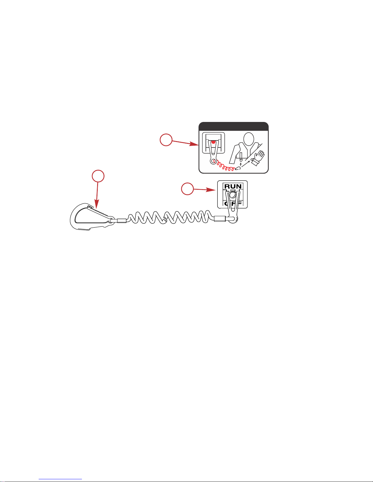
The lanyard cord is usually 122–152 cm (4–5 feet) in length when stretched out,
with an element on one end made to be inserted into the switch and a clip on
the other end for attaching to the operator's PFD or wrist. The lanyard is coiled
to make its at‑rest condition as short as possible to minimize the likelihood of
lanyard entanglement with nearby objects. Its stretched‑out length is made to
minimize the likelihood of accidental activation should the operator choose to
move around in an area close to the normal operator's position. If it is desired
to have a shorter lanyard, wrap the lanyard around the operator's wrist or leg,
or tie a knot in the lanyard.
a - Lanyard cord clip
b - Lanyard decal
c - Lanyard stop switch
Read the following Safety Information before proceeding.
Important Safety Information: The purpose of a lanyard stop switch is to stop
the engine when the operator moves far enough away from the operator's
position to activate the switch. This would occur if the operator accidentally falls
overboard or moves within the boat a sufficient distance from the operator's
position. Falling overboard and accidental ejections are more likely to occur in
certain types of boats such as low sided inflatables, bass boats, high
performance boats, and light, sensitive handling fishing boats operated by a
hand tiller. Falling overboard and accidental ejections are also likely to occur as
a result of poor operating practices such as sitting on the back of the seat or
gunwale at planing speeds, standing at planing speeds, sitting on elevated
fishing boat decks, operating at planing speeds in shallow or obstacle infested
waters, releasing your grip on a steering wheel or tiller handle that is pulling in
one direction, drinking alcohol or consuming drugs, or daring high speed boat
maneuvers.
c
a
b
53910
OFF
RUN
ATTACH LANYARD
GENERAL INFORMATION
eng 3
Page 14
While activation of the lanyard stop switch will stop the engine immediately, a
boat will continue to coast for some distance depending upon the velocity and
degree of any turn at shut down. However, the boat will not complete a full
circle. While the boat is coasting, it can cause injury to anyone in the boat's
path as seriously as the boat would when under power.
We strongly recommend that other occupants be instructed on proper starting
and operating procedures should they be required to operate the engine in an
emergency (if the operator is accidentally ejected).
!
WARNING
If the operator falls out of the boat, stop the engine immediately to reduce the
possibility of serious injury or death from being struck by the boat. Always
properly connect the operator to the stop switch using a lanyard.
!
WARNING
Avoid serious injury or death from deceleration forces resulting from
accidental or unintended stop switch activation. The boat operator should
never leave the operator's station without first disconnecting the stop switch
lanyard from the operator.
Accidental or unintended activation of the switch during normal operation is
also a possibility. This could cause any, or all, of the following potentially
hazardous situations:
• Occupants could be thrown forward due to unexpected loss of forward
motion ‑ a particular concern for passengers in the front of the boat who
could be ejected over the bow and possibly struck by the gearcase or
propeller.
• Loss of power and directional control in heavy seas, strong current, or
high winds.
• Loss of control when docking.
KEEP THE LANYARD STOP SWITCH AND LANYARD CORD IN GOOD
OPERATING CONDITION
Before each use, check to ensure the lanyard stop switch works properly. Start
the engine and stop it by pulling the lanyard cord. If the engine does not stop,
have the switch repaired before operating the boat.
Before each use, visually inspect the lanyard cord to ensure it is in good
working condition and that there are no breaks, cuts, or wear to the cord.
Check that the clips on the ends of the cord are in good condition. Replace any
damaged or worn lanyard cords.
GENERAL INFORMATION
4 eng
Page 15
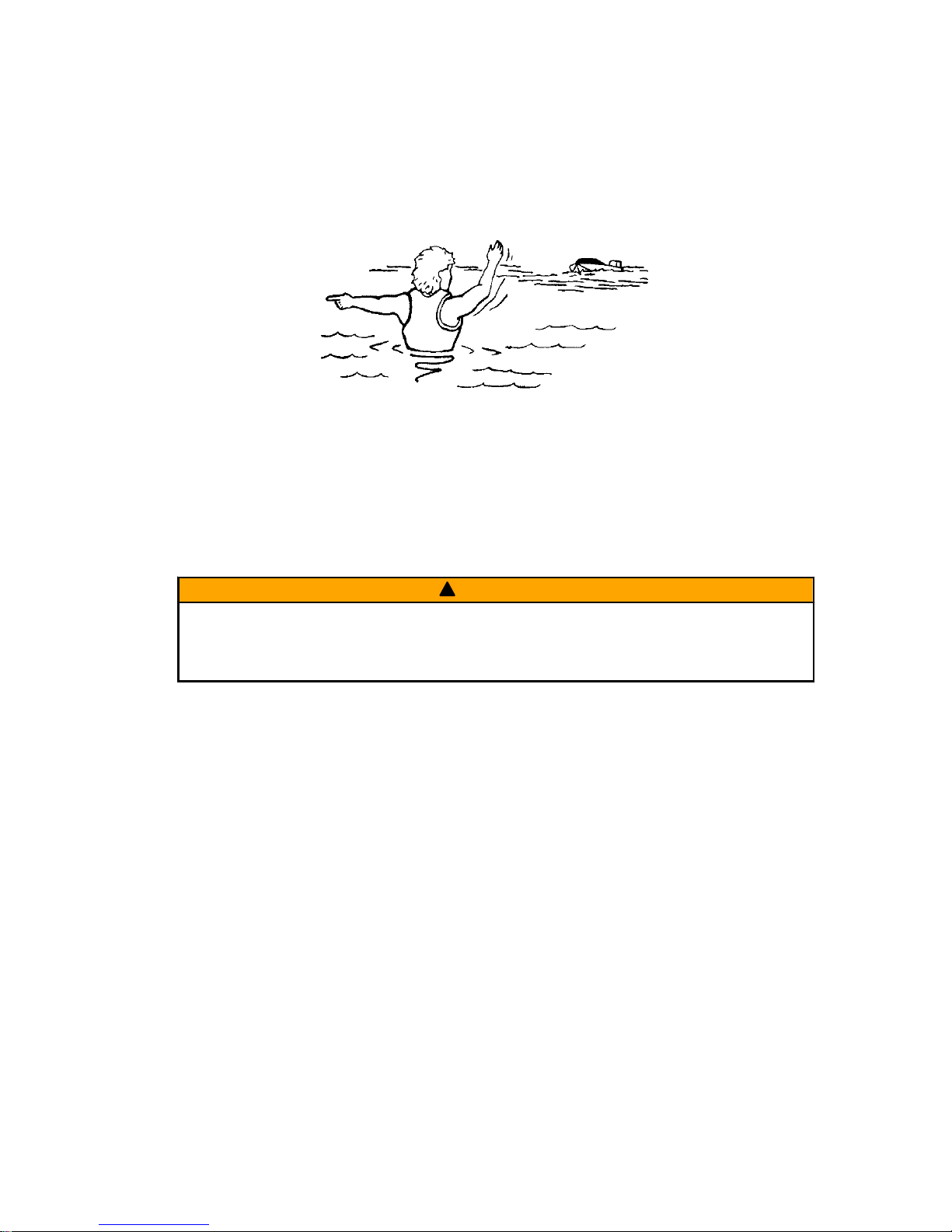
Protecting People in the Water
WHILE YOU ARE CRUISING
It is very difficult for a person standing or floating in the water to take quick
action to avoid a boat heading in his/her direction, even at slow speed.
21604
Always slow down and exercise extreme caution any time you are boating in an
area where there might be people in the water.
Whenever a boat is moving (coasting) and the outboard gear shift is in neutral
position, there is sufficient force by the water on the propeller to cause the
propeller to rotate. This neutral propeller rotation can cause serious injury.
WHILE THE BOAT IS STATIONARY
!
WARNING
A spinning propeller, a moving boat, or any solid device attached to the boat
can cause serious injury or death to swimmers. Stop the engine immediately
whenever anyone in the water is near your boat.
Shift the outboard into neutral and shut off the engine before allowing people to
swim or be in the water near your boat.
Exhaust Emissions
BE ALERT TO CARBON MONOXIDE POISONING
Carbon monoxide (CO) is a deadly gas that is present in the exhaust fumes of
all internal combustion engines, including the engines that propel boats, and
the generators that power boat accessories. By itself, CO is odorless, colorless,
and tasteless, but if you can smell or taste engine exhaust, you are inhaling
CO.
Early symptoms of carbon monoxide poisoning, which are similar to the
symptoms of seasickness and intoxication, include headache, dizziness,
drowsiness, and nausea.
GENERAL INFORMATION
eng 5
Page 16

!
WARNING
Inhaling engine exhaust gases can result in carbon monoxide poisoning,
which can lead to unconsciousness, brain damage, or death. Avoid exposure
to carbon monoxide.
Stay clear from exhaust areas when engine is running. Keep the boat
well‑ventilated while at rest or underway.
STAY CLEAR OF EXHAUST AREAS
Engine exhaust gases contain harmful carbon monoxide. Avoid areas of
concentrated engine exhaust gases. When engines are running, keep
swimmers away from the boat, and do not sit, lie, or stand on swim platforms or
boarding ladders. While underway, do not allow passengers to be positioned
immediately behind the boat (platform dragging, teak/body surfing). This
dangerous practice not only places a person in an area of high engine exhaust
concentration, but also subjects them to the possibility of injury from the boat
propeller.
GOOD VENTILATION
Ventilate the passenger area, open side curtains or forward hatches to remove
fumes.
Example of desired air flow through the boat:
21622
POOR VENTILATION
Under certain running and/or wind conditions, permanently enclosed or canvas
enclosed cabins or cockpits with insufficient ventilation may draw in carbon
monoxide. Install one or more carbon monoxide detectors in your boat.
Although the occurrence is rare, on a very calm day, swimmers and
passengers in an open area of a stationary boat that contains, or is near, a
running engine may be exposed to a hazardous level of carbon monoxide.
GENERAL INFORMATION
6 eng
Page 17
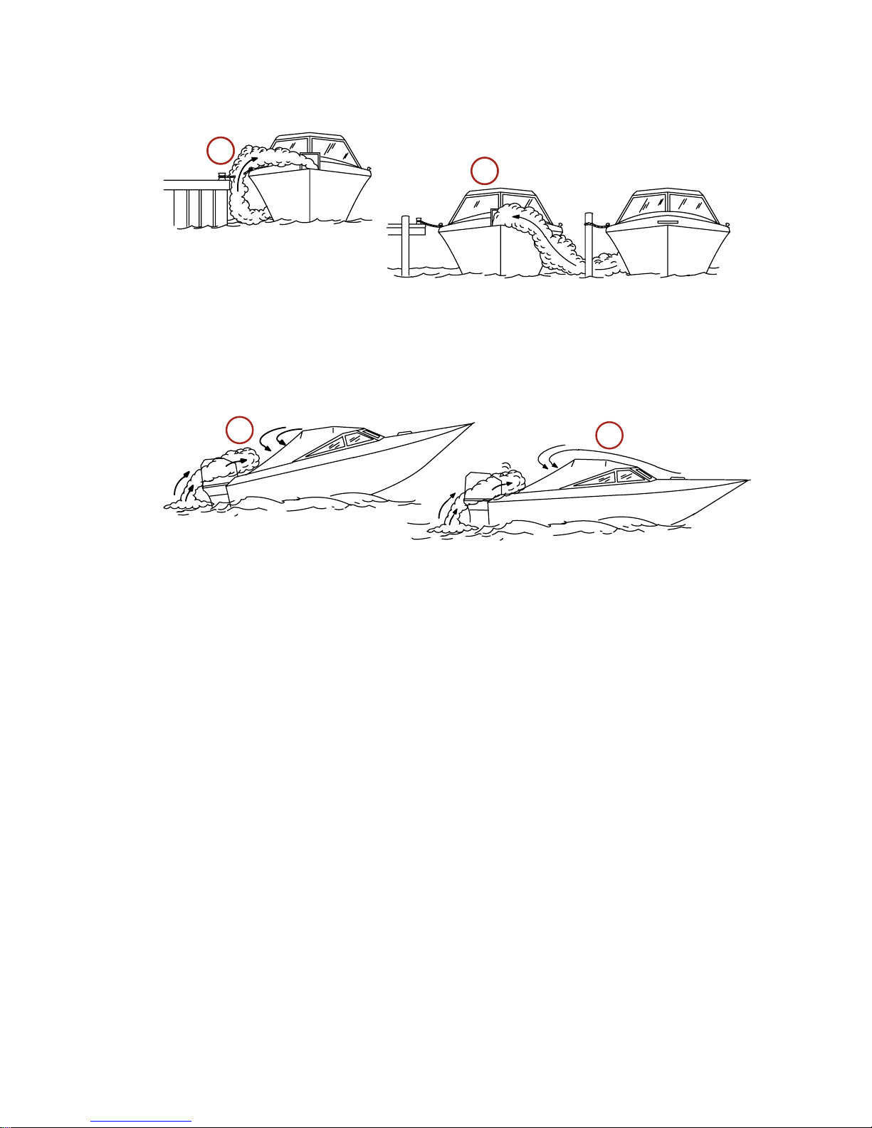
1. Examples of poor ventilation while the boat is stationary:
a - Operating the engine when the boat is moored in a confined space
b - Mooring close to another boat that has its engine operating
2. Examples of poor ventilation while the boat is moving:
a - Operating the boat with the trim angle of the bow too high
b - Operating the boat with no forward hatches open (station wagon effect)
Passenger Safety Message ‑ Pontoon Boats and Deck Boats
Whenever the boat is in motion, observe the location of all passengers. Do not
allow any passengers to stand or use seats other than those designated for
traveling faster than idle speed. A sudden reduction in boat speed, such as
plunging into a large wave or wake, a sudden throttle reduction, or a sharp
change of boat direction, could throw them over the front of the boat. Falling
over the front of the boat between the two pontoons will position them to be run
over by the outboard.
BOATS HAVING AN OPEN FRONT DECK
No one should ever be on the deck in front of the fence while the boat is in
motion. Keep all passengers behind the front fence or enclosure.
21626
a
b
a
b
21628
GENERAL INFORMATION
eng 7
Page 18
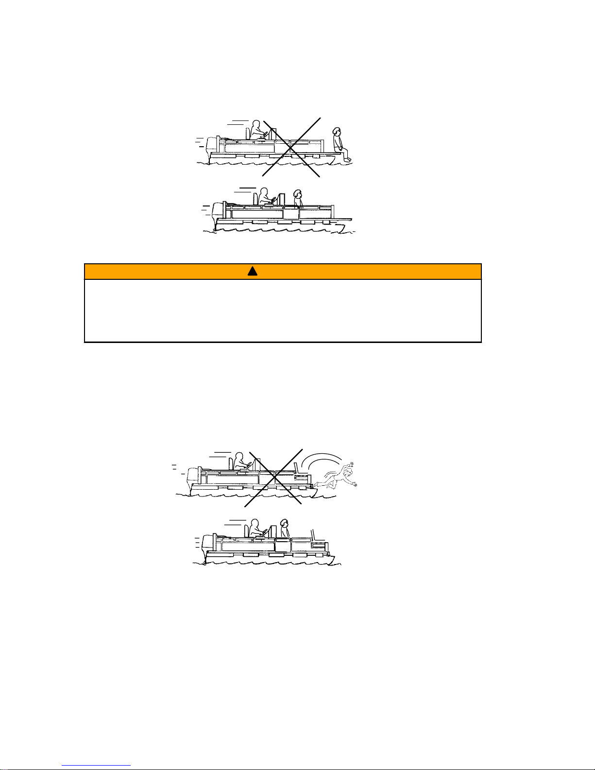
Persons on the front deck could easily be thrown overboard or persons
dangling their feet over the front edge could get their legs caught by a wave
and pulled into the water.
26782
!
WARNING
Sitting or standing in an area of the boat not designed for passengers at
speeds above idle can cause serious injury or death. Stay back from the front
end of deck boats or raised platforms and remain seated while the boat is in
motion.
BOATS WITH FRONT MOUNTED, RAISED PEDESTAL FISHING SEATS
Elevated fishing seats are not intended for use when the boat is traveling faster
than idle or trolling speed. Sit only in seats designated for traveling at faster
speeds.
Any unexpected, sudden reduction in boat speed could result in the elevated
passenger falling over the front of the boat.
26783
GENERAL INFORMATION
8 eng
Page 19
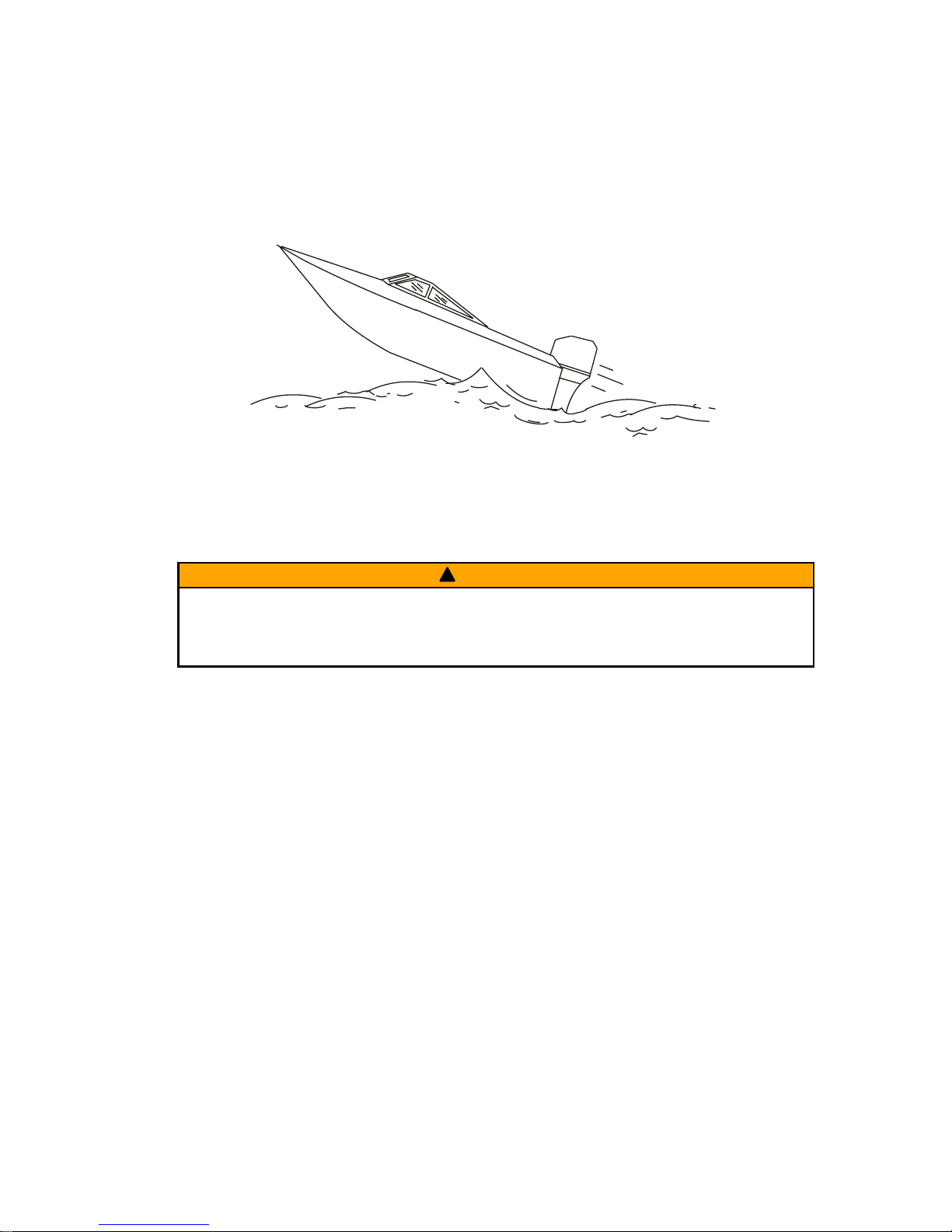
Wave and Wake Jumping
Operating recreational boats over waves and wake is a natural part of boating.
However, when this activity is done with sufficient speed to force the boat hull
partially or completely out of the water, certain hazards arise, particularly when
the boat enters the water.
26784
The primary concern is the boat changing direction while in the midst of the
jump. In such case, the landing may cause the boat to veer violently in a new
direction. Such a sharp change in direction can cause occupants to be thrown
out of their seats, or out of the boat.
!
WARNING
Wave or wake jumping can cause serious injury or death from occupants
being thrown within or out of the boat. Avoid wave or wake jumping whenever
possible.
There is another less common hazardous result from allowing your boat to
launch off a wave or wake. If the bow of your boat pitches down far enough
while airborne, upon water contact it may penetrate under the water surface
and submarine for an instant. This will bring the boat to a nearly instantaneous
stop and can send the occupants flying forward. The boat may also steer
sharply to one side.
Impact with Underwater Hazards
Your outboard is equipped with a hydraulic trim and tilt system that also
contains a shock absorbing feature. This feature helps the outboard withstand
damage in the case of impact with an underwater object at low to moderate
speeds. At higher speeds, the force of the impact may exceed the system’s
ability to absorb the energy of the impact and cause serious product damage.
No impact protection exists while in reverse. Use extreme caution when
operating in reverse to avoid striking underwater objects.
GENERAL INFORMATION
eng 9
Page 20
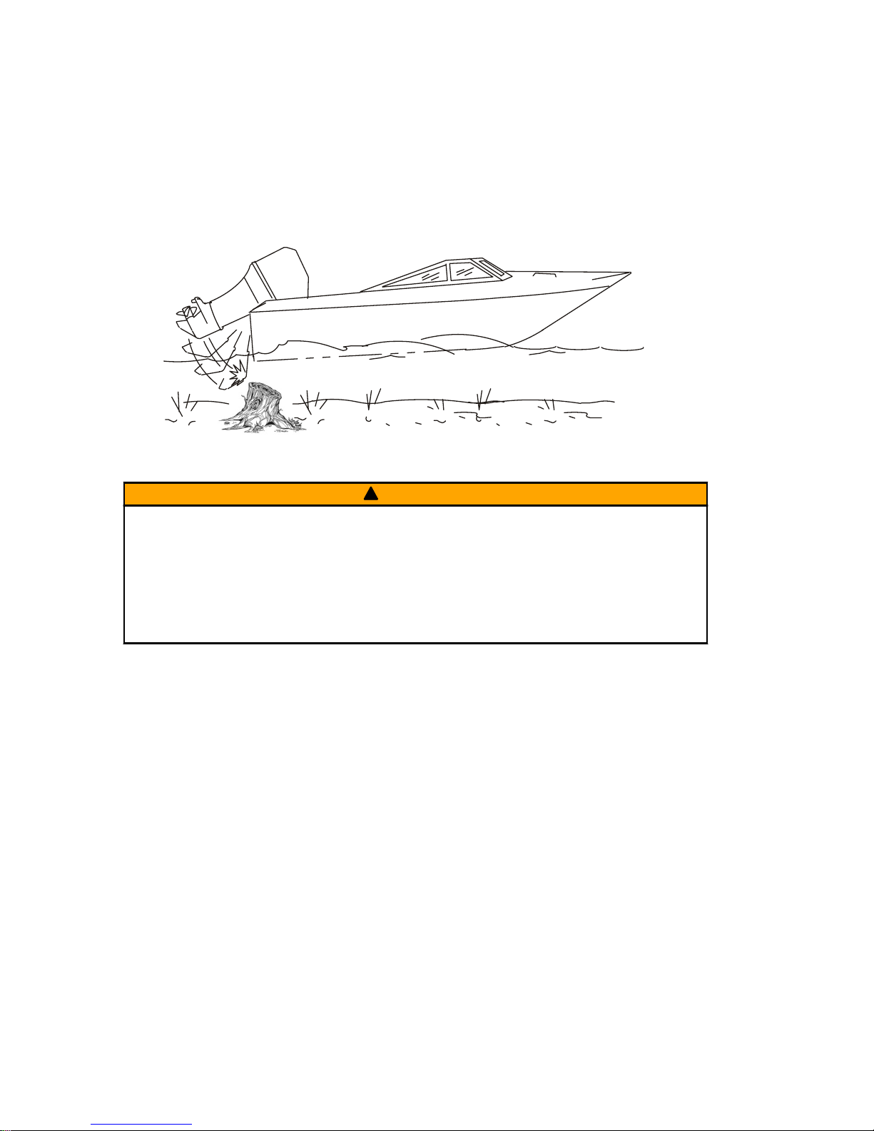
Reduce speed and proceed with caution whenever you drive a boat in shallow
water areas or in areas where you suspect underwater obstacles may exist that
could be struck by the outboard or the boat bottom. The most significant
action you can take to help reduce injury or impact damage from striking
a floating or underwater object is to control the boat speed. Under these
conditions, boat speed should be kept to the minimum planing speed,
typically 24 to 40 km/h (15 to 25 mph).
26785
!
WARNING
Avoid serious injury or death from all or part of an outboard or drive unit
coming into the boat after striking a floating or underwater object. When
operating in waters where objects may be at the surface or just under the
surface of the water, reduce your speed and keep a vigilant lookout.
Examples of objects that can cause engine damage are dredging pipes,
bridge supports, wing dams, trees, stumps, and rocks.
Striking a floating or underwater object could result in any of an infinite number
of situations. Some of these situations could yield the following:
• Part of the outboard or the entire outboard could break loose and fly into
the boat.
• The boat could move suddenly in a new direction. A sharp change in
direction can cause occupants to be thrown out of their seats or out of the
boat.
• The boat's speed could rapidly reduce. This will cause occupants to be
thrown forward or even out of the boat.
• The outboard or boat could sustain impact damage.
After striking a submerged object, stop the engine as soon as possible and
inspect it for any broken or loose parts. If damage is present or suspected, the
outboard should be taken to an authorized dealer for a thorough inspection and
necessary repair.
The boat should also be checked for any hull fractures, transom fractures, or
water leaks. If water leaks are discovered after an impact, immediately activate
the bilge pump.
GENERAL INFORMATION
10 eng
Page 21

Operating a damaged outboard could cause additional damage to other parts
of the outboard or could affect control of the boat. If continued running is
necessary, do so at greatly reduced speeds.
!
WARNING
Operating a boat or engine with impact damage can result in product
damage, serious injury, or death. If the vessel experiences any form of
impact, have an authorized Mercury Marine dealer inspect and repair the
vessel or power package.
Selecting Accessories for Your Outboard
Genuine Mercury Precision or Quicksilver Accessories have been specifically
designed and tested for your outboard. These accessories are available from
Mercury Marine dealers.
IMPORTANT: Check with your dealer before installing accessories. The misuse
of approved accessories or the use of nonapproved accessories can damage
the product.
Some accessories not manufactured or sold by Mercury Marine are not
designed to be safely used with your outboard or outboard operating system.
Read the installation, operation and maintenance manuals for all your selected
accessories.
Refer to Outboard Installation ‑ Accessories Mounted to the Transom
Clamp Bracket for important information on mounting accessories to the
transom clamp bracket.
Safe Boating Recommendations
To safely enjoy the waterways, familiarize yourself with local and all other
governmental boating regulations and restrictions and consider the following
suggestions.
Know and obey all nautical rules and laws of the waterways.
• We recommend that all powerboat operators complete a boating safety
course. In the U.S., the U.S. Coast Guard Auxiliary, the Power Squadron,
the Red Cross, and your state or provincial boating law enforcement
agency provide courses. For more information in the U.S., call the Boat
U.S. Foundation at 1‑800‑336‑BOAT (2628).
Perform safety checks and required maintenance.
• Follow a regular schedule and ensure that all repairs are properly made.
Check safety equipment onboard.
• Here are some suggestions of the types of safety equipment to carry
when boating:
Approved fire extinguishers
Signal devices: flashlight, rockets or flares, flag, and whistle or horn
Tools necessary for minor repairs
GENERAL INFORMATION
eng 11
Page 22

Anchor and extra anchor line
Manual bilge pump and extra drain plugs
Drinking water
Radio
Paddle or oar
Spare propeller, thrust hubs, and an appropriate wrench
First aid kit and instructions
Waterproof storage containers
Spare operating equipment, batteries, bulbs, and fuses
Compass and map or chart of the area
Personal flotation device (one per person onboard)
Watch for signs of weather change and avoid foul weather and rough‑sea
boating.
Tell someone where you are going and when you expect to return.
Passenger boarding.
• Stop the engine whenever passengers are boarding, unloading, or are
near the back (stern) of the boat. Shifting the drive unit into neutral is not
sufficient.
Use personal flotation devices.
• Federal law requires that there be a U.S. Coast Guard‑approved life
jacket (personal flotation device), correctly sized and readily accessible
for every person onboard, plus a throwable cushion or ring. We strongly
advise that everyone wear a life jacket at all times while in the boat.
Prepare other boat operators.
• Instruct at least one person onboard in the basics of starting and
operating the engine and boat handling in case the driver becomes
disabled or falls overboard.
Do not overload your boat.
• Most boats are rated and certified for maximum load (weight) capacities
(refer to your boat's capacity plate). Know your boat's operating and
loading limitations. Know if your boat will float if it is full of water. When in
doubt, contact your authorized Mercury Marine dealer or the boat
manufacturer.
Ensure that everyone in the boat is properly seated.
GENERAL INFORMATION
12 eng
Page 23

• Do not allow anyone to sit or ride on any part of the boat that was not
intended for such use. This includes the backs of seats, gunwales,
transom, bow, decks, raised fishing seats, and any rotating fishing seat.
Passengers should not sit or ride anywhere that sudden unexpected
acceleration, sudden stopping, unexpected loss of boat control, or sudden
boat movement could cause a person to be thrown overboard or into the
boat. Ensure that all passengers have a proper seat and are in it before
any boat movement.
Never operate a boat while under the influence of alcohol or drugs. It is
the law.
• Alcohol or drugs can impair your judgment and greatly reduce your ability
to react quickly.
Know your boating area and avoid hazardous locations.
Be alert.
• The operator of the boat is responsible by law to maintain a proper
lookout by sight and hearing. The operator must have an unobstructed
view particularly to the front. No passengers, load, or fishing seats should
block the operator's view when the boat is above idle or planing transition
speed. Watch out for others, the water, and your wake.
Never drive your boat directly behind a water skier.
• Your boat traveling at 40 km/h (25 mph) will overtake a fallen skier who is
61 m (200 ft) in front of you in five seconds.
Watch fallen skiers.
• When using your boat for waterskiing or similar activities, always keep a
fallen or down skier on the operator's side of the boat while returning to
attend to the skier. The operator should always have the down skier in
sight and never back up to the skier or anyone in the water.
Report accidents.
• Boat operators are required by law to file a boating accident report with
their state boating law enforcement agency when their boat is involved in
certain boating accidents. A boating accident must be reported if 1) there
is loss of life or probable loss of life, 2) there is personal injury requiring
medical treatment beyond first aid, 3) there is damage to boats or other
property where the damage value exceeds $500.00, or 4) there is
complete loss of the boat. Seek further assistance from local law
enforcement.
GENERAL INFORMATION
eng 13
Page 24

Specifications
Models
200
Pro
225 250
250
Pro
Horsepower 200 225 250 250
Kilowatts 149 165 184 184
Full throttle RPM
range
5800–6400
Idle RPM in neutral
gear*
550
Number of cylinders 6
Displacement 2,598 cc (158.5 cid)
Cylinder bore 82 mm (3.23 in.)
Stroke 82 mm (3.23 in.)
Spark plug NGK ILFR6G‑E
Spark plug gap 0.8 mm (0.0315 in.)
Spark plug hex size 16 mm
Gear ratio
1 inch shaft
1.85:1
Recommended
gasoline
Refer to Fuel and Oil
Recommended oil
Refer to Fuel and Oil
Gearcase capacity
Refer to Maintenance ‑ Gearcase Lubrication
Engine oil capacity
with oil filter
replacement
7.0 Liter (7.4 US qt)
Required battery type 12‑volt AGM (absorbed glass mat) battery
USA (SAE) battery
type
800 minimum marine cranking amps (MCA) with a
minimum reserve capacity of 135 minutes RC25 rating
International (EN)
battery type
975 minimum cold cranking amps (CCA) with a
minimum of 65 amp hours (Ah)
* Engine at normal operation temperature.
Models
300 300 Pro 350 350 Pro
Horsepower 300 300 350 350
Kilowatts 221 221 261 261
Full throttle RPM range 5800–6400
Idle RPM in neutral gear* 550 600
Number of cylinders 6
GENERAL INFORMATION
14 eng
Page 25
Models 300 300 Pro 350 350 Pro
Displacement 2,598 cc (158.5 cid)
Cylinder bore 82 mm (3.23 in.)
Stroke 82 mm (3.23 in.)
Spark plug NGK ILFR6G‑E
Spark plug gap 0.8 mm (0.0315 in.)
Spark plug hex size 16 mm
Gear
Ratio
1 inch shaft 1.85:1 1.75:1
1.25 inch shaft 1.75:1 1.75:1 1.75:1
Recommended gasoline
Refer to Fuel and Oil
Recommended oil
Refer to Fuel and Oil
Gearcase capacity
Refer to Maintenance ‑ Gearcase Lubrication
Engine oil capacity with oil
filter replacement
7.0 Liter (7.4 US qt)
Required battery type 12‑volt AGM (absorbed glass mat) battery
USA (SAE) battery type
800 minimum marine cranking amps (MCA)
with a minimum reserve capacity of 135
minutes RC25 rating
International (EN) battery
type
975 minimum cold cranking amps (CCA) with a
minimum of 65 amp hours (Ah)
* Engine at normal operation temperature.
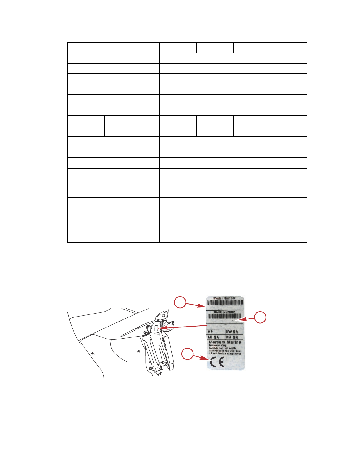
Recording Serial Number
It is important to record this number for future reference. The serial number is
located on the outboard, as shown.
a - Model number
b - Serial number
c - Certified Europe Insignia (as applicable)
a
XXXXXXXXX
XXXXXXXX
XXXX
c
b
62546
GENERAL INFORMATION
eng 15
Page 26
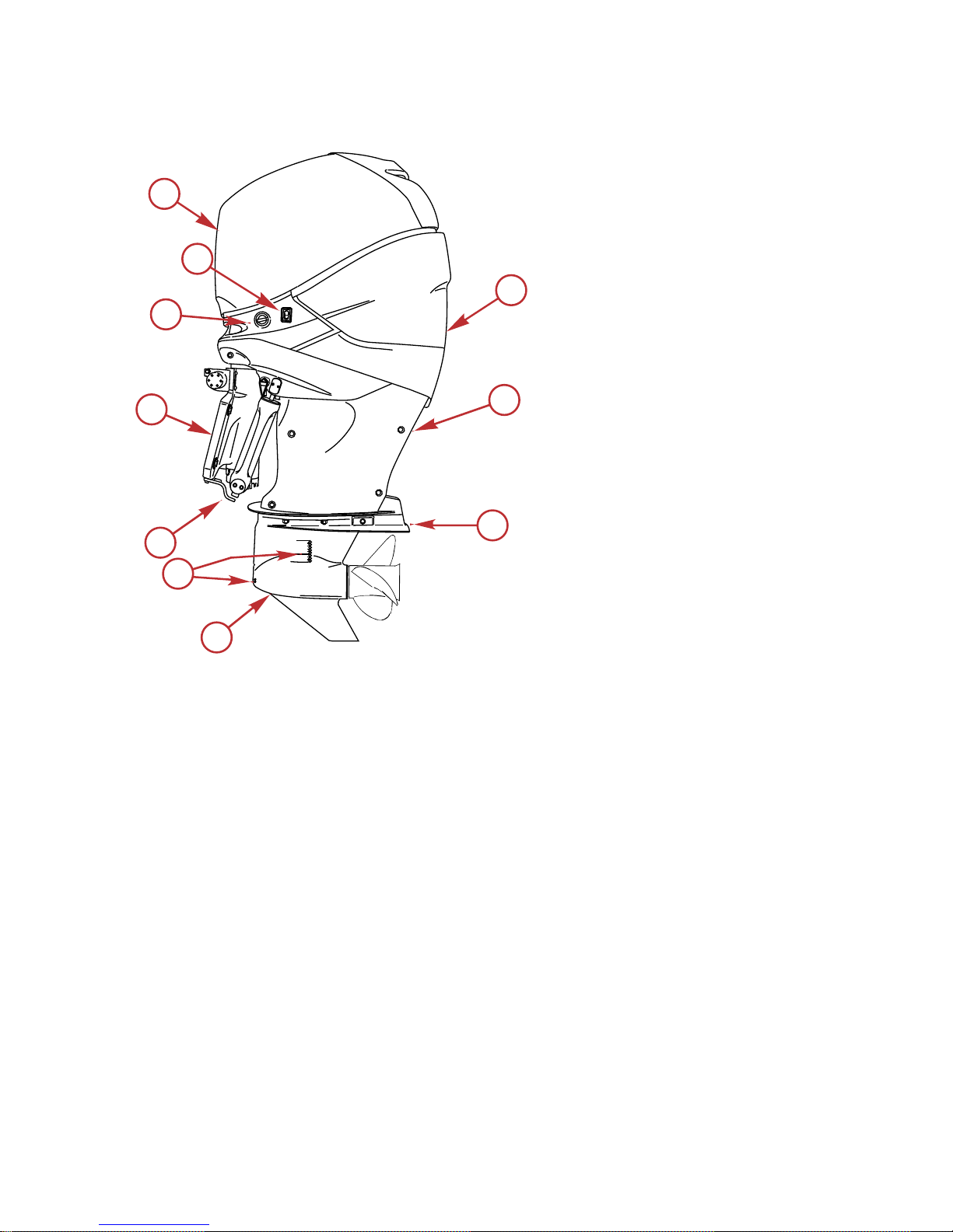
Component Identification 200–300
a - Rear cowl
b - Lower cowl chaps
c - Antiventilation plate
d - Gearcase
e - Cooling water intake
holes
f - Spray plate
g - Pedestal
h - Engine flush
i - Auxiliary tilt switch
j - Top cowl
j
i
h
g
f
e
d
c
b
a
28919
GENERAL INFORMATION
16 eng
Page 27
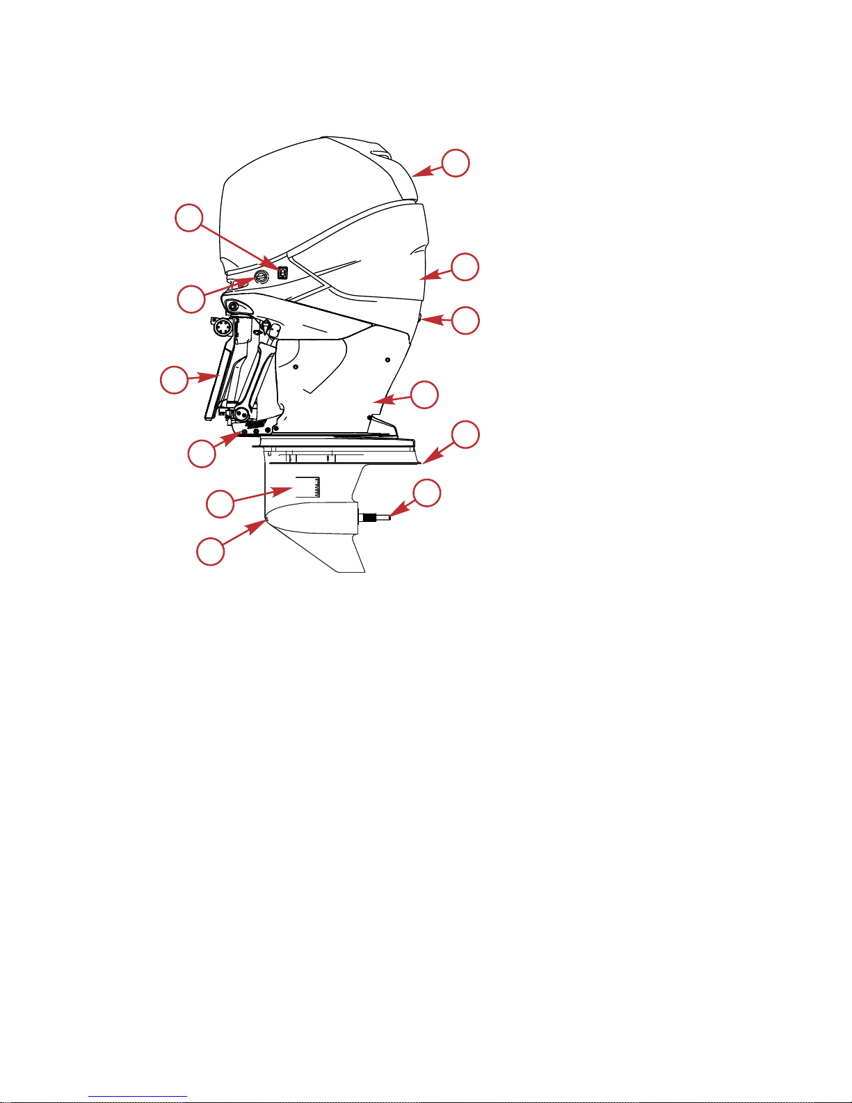
350 HP Component Identification
a - Top cowl
b - Rear cowl
c - Idle relief exhaust
d - Lower cowl chaps
e - Antiventilation plate
f - Propeller shaft
g - Low water intake holes
h - Water intake holes
i - Trim guide plates
j - Pedestal
k - Engine flush
l - Auxiliary tilt switch
Propeller Selection
The propeller on your outboard is one of the most important components in the
propulsion system. An improper propeller choice can significantly affect the
performance of your boat and could result in damage to the outboard engine.
When choosing a propeller, a full selection of aluminum and stainless steel
propellers specifically designed for your outboard are available through
Mercury Marine. To view the entire product offering and find the correct
propeller that is best suited for your application, visit
www.mercmarinepropellers.com or see your local authorized Mercury dealer.
SELECTING THE CORRECT PROPELLER
An accurate tachometer for measuring engine speed is important in choosing
the correct propeller.
57122
a
b
c
d
e
f
g
h
k
l
i
j
GENERAL INFORMATION
eng 17
Page 28
Choose a propeller for your boating application that will allow the engine to
operate within the specified full throttle operating range. When operating the
boat at full throttle under normal load conditions, the engine RPM should be in
the upper half of the recommended full throttle RPM range. Refer to
Specifications. If engine RPM is above that range, select a propeller of
increased pitch in order to reduce engine RPM. If engine RPM is below the
recommended range, select a propeller of reduced pitch to increase engine
RPM.
IMPORTANT: To ensure proper fit, and performance, Mercury Marine
recommends the use of Mercury or Quicksilver branded propellers and
mounting hardware.
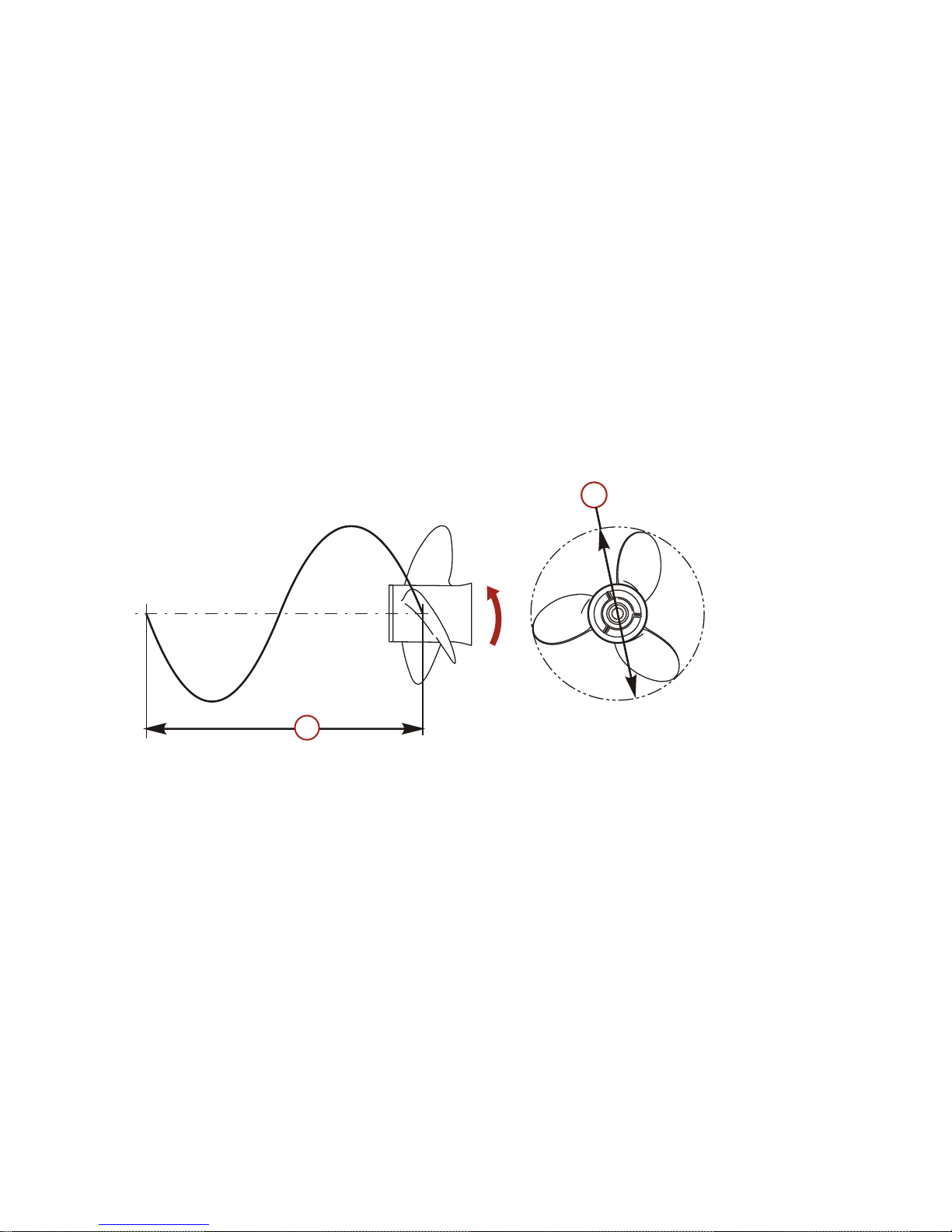
Propellers are designated by the diameter, pitch, number of blades, and
material. The diameter and pitch are stamped (cast) into the side or the end of
the propeller hub. The first number represents the diameter of the propeller and
the second number represents the pitch. For example, 14x19 represents a
propeller with a 14 inch diameter and 19 inches of pitch.
a - Diameter
b - Pitch ‑ Travel during one revolution
The following are some propeller basics that will help you determine the correct
propeller for your boating application.
Diameter ‑ The diameter is the distance across the imaginary circle that is
made when the propeller rotates. The correct diameter for each propeller has
been predetermined for the design of your outboard. However, when more than
one diameter is available for the same pitch, use a larger diameter for heavy
boat applications and a smaller diameter for lighter applications.
Pitch ‑ The pitch is the theoretical distance, in inches, that a propeller travels
forward during one revolution. Pitch can be thought of similar to gears in a car.
The lower the gear, the faster the car will accelerate, but with lower overall top
speed. Likewise, a lower pitch propeller will accelerate quickly, but top‑end
speed will be reduced. The higher the propeller pitch the faster the boat will
usually go; though typically slowing acceleration.
a
b
22669
GENERAL INFORMATION
18 eng
Page 29

Determining the correct pitch size ‑ First, check the full throttle RPM under
normal load condition. If the full throttle RPM is within the recommended range,
select a replacement or upgrade propeller with the same pitch as the current
propeller.
• Adding 1 inch of pitch will reduce the full throttle RPM by 150 to 200
• Subtracting 1 inch of pitch will increase full throttle RPM by 150 to 200
• Upgrading from a 3‑blade propeller to a 4‑blade propeller will generally
decrease full throttle RPM by 50 to 100
IMPORTANT: Avoid damage to the engine. Never use a propeller that allows
the engine to exceed the recommended full throttle RPM range when under
normal full throttle operation.
PROPELLER MATERIAL
Most propellers manufactured by Mercury Marine are made from either
aluminum or stainless steel. Aluminum is suitable for general purpose use and
is standard equipment on many new boats. Stainless steel is over five times
more durable than aluminum and typically provides performance gains in
acceleration and top end speed due to design efficiencies. Stainless steel
propellers also come in a larger variety of sizes and styles that allow you to dial
in the ultimate performance for your boat.
3 BLADE VS. 4 BLADE
Available in many sizes of both aluminum and stainless, 3 and 4‑blade
propellers have unique performance characteristics. In general, 3‑blade
propellers offer good all around performance and higher top speed than
4‑blade propellers. However, 4‑blade propellers are usually faster to plane and
more efficient at cruising speeds, but lack the top end speed of a 3‑blade
propeller.
GENERAL INFORMATION
eng 19
Page 30
Trailering Boat/Outboard
When transporting the boat on a trailer, the outboard should be positioned and
supported in one of the following ways:
1. If the boat trailer provides sufficient ground clearance, the outboard may
be tilted down to the vertical operating position with no additional support
required.
28780
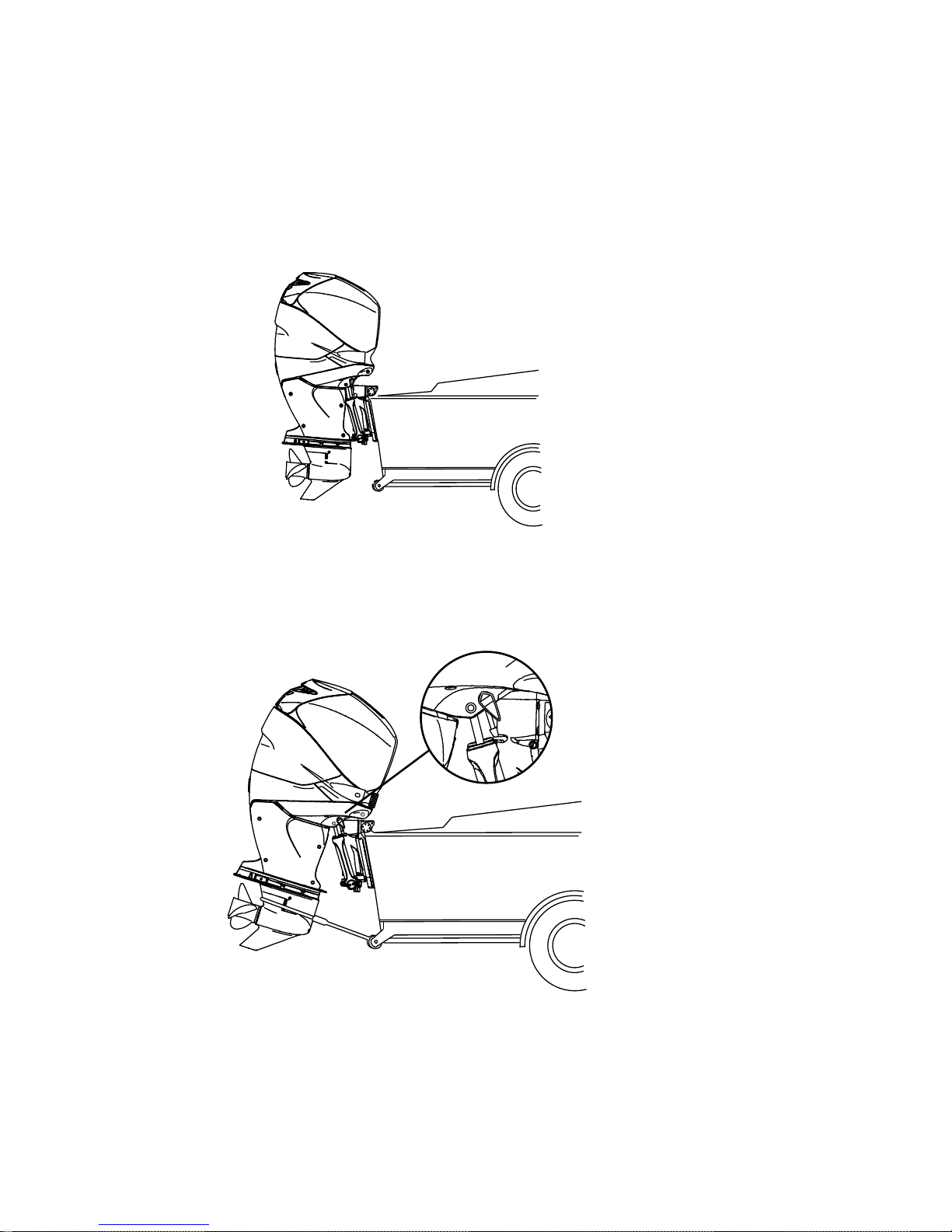
2. If additional ground clearance is required, the outboard should be tilted up
and supported using the outboard's tilt support bracket (trailering position)
in addition to using an accessory transom support device. Refer to
Features and Controls ‑ Power Trim and Tilt.
28924
TRANSPORTING
20 eng
Page 31

3. For maximum ground clearance, the outboard can be tilted to the full tilt
position and supported using the outboard tilt support bracket or an
accessory transom support device.
28779
Additional clearance may be required for railroad crossings, driveways, and
trailer bouncing. See your local dealer for recommendations.
IMPORTANT: Do not rely on the power trim/tilt system to maintain proper
ground clearance for trailering. The power trim/tilt system is not intended to
support the outboard for trailering.
TRANSPORTING
eng 21
Page 32

Fuel Requirements
IMPORTANT: Use of improper gasoline can damage your engine. Engine
damage resulting from the use of improper gasoline is considered misuse
of the engine and will not be covered under the limited warranty.
Mercury outboard engines will operate satisfactorily with any major brand of
unleaded gasoline that meets the following specifications:
MODELS 350, 350 PRO, 400R
USA and Canada ‑ A posted pump octane rating of 91 (R+M)/2 is required for
best performance. A posted pump octane rating of 89 (R+M)/2 minimum is
acceptable, however, performance losses may occur. Do not use leaded
gasoline.
Outside USA and Canada ‑ A posted pump octane rating of 95 RON is
required for best performance. A posted pump octane rating of 93 RON
minimum is acceptable, however, performance losses may occur. Do not use
leaded gasoline.
MODELS 250 PRO, 300 PRO, 300
USA and Canada ‑ A posted pump octane rating of 91 (R+M)/2 octane is
required for best performance. A posted pump octane rating of 87 (R+M)/2
minimum is acceptable, however, performance losses may occur. Do not use
leaded gasoline.
Outside USA and Canada ‑ A posted pump octane rating of 95 RON is
required for best performance. A posted pump octane rating of 91 RON
minimum is acceptable, however, performance losses may occur. Do not use
leaded gasoline.
MODELS 200 PRO, 225, AND 250
USA and Canada ‑ A posted pump octane rating of 87 (R+M)/2 is acceptable.
Premium gasoline is also acceptable. Do not use leaded gasoline.
Outside USA and Canada ‑ A posted pump octane rating of 91 RON is
acceptable. Premium gasoline is also acceptable. Do not use leaded gasoline.
USING REFORMULATED (OXYGENATED) GASOLINE (USA ONLY)
Reformulated gasoline is required in certain areas of the USA and is
acceptable for use in your Mercury Marine engine. The only oxygenate
currently in use in the USA is alcohol (ethanol, methanol, or butanol).
GASOLINES CONTAINING ALCOHOL
Bu16 Butanol Fuel Blends
Fuel blends of up to 16.1% butanol (Bu16) that meet the published Mercury
Marine fuel rating requirements are an acceptable substitute for unleaded
gasoline. Contact your boat manufacturer for specific recommendations on
your boat's fuel system components (fuel tanks, fuel lines, and fittings).
FUEL AND OIL
22 eng
Page 33

Methanol and Ethanol Fuel Blends
IMPORTANT: The fuel system components on your Mercury Marine engine will
withstand up to 10% alcohol (methanol or ethanol) content in the gasoline. Your
boat's fuel system may not be capable of withstanding the same percentage of
alcohol. Contact your boat manufacturer for specific recommendations on your
boat's fuel system components (fuel tanks, fuel lines, and fittings).
Be aware that gasoline containing methanol or ethanol may cause increased:
• Corrosion of metal parts
• Deterioration of rubber or plastic parts
• Fuel permeation through the rubber fuel lines
• Likelihood of phase separation—water and alcohol separating from the
gasoline in the fuel tank
!
WARNING
Fuel leakage is a fire or explosion hazard, which can cause serious injury or
death. Periodically inspect all fuel system components for leaks, softening,
hardening, swelling, or corrosion, particularly after storage. Any sign of
leakage or deterioration requires replacement before further engine
operation.
IMPORTANT: If you use gasoline that contains or might contain methanol or
ethanol, you must increase the frequency of inspection for leaks and
abnormalities.
IMPORTANT: When operating a Mercury Marine engine on gasoline containing
methanol or ethanol, do not store the gasoline in the fuel tank for long periods.
Cars normally consume these blended fuels before they can absorb enough
moisture to cause trouble; boats often sit idle long enough for phase separation
to take place. Internal corrosion may occur during storage if alcohol has
washed protective oil films from internal components.
Fuel Additives
To minimize carbon deposit buildup in the engine, add Mercury or Quicksilver
Quickleen Engine and Fuel System Cleaner to the engine's fuel at each tank
throughout the boating season. Use the additive as directed on the container.
Low Permeation Fuel Hose Requirement
Required for outboards manufactured for sale, sold, or offered for sale in the
United States.
• The Environmental Protection Agency (EPA) requires that any outboard
manufactured after January 1, 2009, must use low permeation fuel hose
for the primary fuel hose connecting the fuel tank to the outboard.
• Low permeation hose is USCG Type B1‑15 or Type A1‑15, defined as not
exceeding 15 g/m²/24 h with CE 10 fuel at 23 °C as specified in SAE J
1527 ‑ marine fuel hose.
FUEL AND OIL
eng 23
Page 34

Fuel Demand Valve
Some boat fuel systems incorporate a fuel demand valve between the fuel tank
and the engine and others do not. This engine can be operated with or without
a fuel demand valve.
The fuel demand valve has a manual release. The manual release can be used
(pushed in) to open (bypass) the valve in case of a fuel blockage in the valve.
a - Fuel demand valve ‑ installed in the
fuel hose between the fuel tank and
primer bulb
b - Manual release
c - Vent/water drain holes
Engine Oil Recommendations
200–350 HP MODELS
Mercury 25W‑40 NMMA certified FC‑W Catalyst Compatible® Synthetic Blend
Marine Engine Oil is the preferred choice for general, all‑temperature use in all
200–350 HP Verado engines.
57244
In lieu of the preferred grade oil, the following may be used (listed in the order
of preference):
• Mercury 25W40 Mineral Catalyst Compatible FC‑W® Oil
• 25W‑40 NMMA certified FC‑W® Marine Engine Oil
Checking and Adding Engine Oil
IMPORTANT: Do not overfill. Tilt the outboard out/up past vertical for
approximately one minute to allow trapped oil to drain back to the oil sump. The
outboard must be in a vertical (not tilted) position when checking engine oil. For
accurate readings, check oil only when engine is cold or after engine has not
run for at least an hour.
a
c
b
46273
FUEL AND OIL
24 eng
Page 35

1. Before starting (cold engine) tilt outboard out/up past vertical to allow
trapped oil to drain back to the oil sump. Allow outboard to remain tilted
for approximately one minute.
2. Tilt the outboard to a vertical operating position.
3.
Remove the top cowl. Refer to Maintenance ‑ Cowl Removal and
Installation.
4. Pull out the dipstick. Wipe the dipstick end with a clean rag or towel and
push it back in all the way.
5. Pull the dipstick back out again and observe the oil level. Oil should be in
the operating range (crosshatched region).
IMPORTANT: Do not try to fill the oil level to the top of the operating range
(crosshatched region). Oil level is correct as long as it appears in the operating
range (crosshatched region).
a - Oil level operating range
a
15730
FUEL AND OIL
eng 25
Page 36

6. If the oil level is below the operating range (crosshatched region), remove
the oil filler cap and add approximately 500 ml (16 oz) of specified
outboard motor oil.
28761
7. Tilt outboard out/up past vertical to allow trapped oil to drain back to the
oil sump. Allow outboard to remain tilted for approximately one minute.
8. Tilt the outboard to a vertical operating position and check the dipstick.
9. Repeat the process until oil level is on the operating range (crosshatched
region). Do not try to fill to the upper end of the operating range
(crosshatched region).
IMPORTANT: Inspect oil for signs of contamination. Oil contaminated with
water will have a milky color to it; oil contaminated with fuel will have a strong
fuel smell. If contaminated oil is noticed, have the engine checked by your
dealer.
10. Push the dipstick back in all the way.
11. Install the oil fill cap hand tight.
12. Install the top cowl.
FUEL AND OIL
26 eng
Page 37

Panel Mount Control Features and Operation
1. Operation of the shift and throttle is controlled by the movement of the
control handle. Push the control handle forward from neutral to the first
detent for forward gear. Continue pushing forward to increase speed. Pull
the control handle back from neutral to the first detent for reverse gear.
Continue pulling back to increase speed.
F
N
R
3413
2. Shift lock ‑ Pressing the shift lock allows the engine to shift. The shift lock
must always be pressed when moving the control handle out of the
neutral position.
3428
3. Trim switch (if equipped) ‑ Pressing the trim switch will trim the engine up
or down.
5152
FEATURES AND CONTROLS
eng 27
Page 38

4. Throttle only button ‑ Allows the boat operator to increase engine RPM for
warm‑up, without shifting the engine into gear. To engage throttle only,
move the control handle into the neutral position. Press the throttle only
button while moving the control handle ahead to the forward detent. The
horn indicates throttle only is engaged. Advance throttle to increase
engine RPM. To disengage, return the control handle to the neutral
position. Engine RPM is limited to prevent engine damage.
3416
5. Stop/start button ‑ Allows the boat operator to start or stop the engine
without using the ignition key. The ignition key must be in the "ON"
position to start the engine.
3414
6. Lanyard stop switch ‑ Turns the ignition off whenever the operator (when
attached to the lanyard) moves far enough away from the operator's
position to activate the switch.
a - Lanyard stop switch
a
22964
FEATURES AND CONTROLS
28 eng
Page 39

7. Control handle tension adjustment screw ‑ This screw can be adjusted to
increase or decrease the tension on the control handle (cover must be
removed). This will help prevent unwanted motion of the handle in rough
water. Turn screw clockwise to increase tension and counterclockwise to
decrease tension. Adjust to tension desired.
8. Detent tension adjustment screw ‑ This screw can be adjusted to increase
or decrease the effort to move control handle out of detent positions
(cover must be removed). Turning the screw clockwise will increase
tension. Adjust to tension desired.
a - Detent tension adjustment screw
b - Control handle tension adjustment
screw
Slim Binnacle Control Features and Operation
DTS SLIM BINNACLE SINGLE HANDLE CONSOLE FEATURES AND
OPERATION
1. Operation of shift and throttle is controlled by the movement of the control
handle. Push the control handle forward from neutral to the first detent for
forward gear. Continue pushing forward to increase speed. Pull the
control handle back from neutral to the first detent for reverse gear.
Continue pushing back to increase speed.
5171
+
-
a
b
FEATURES AND CONTROLS
eng 29
Page 40

2. Trim Switch (if equipped) ‑ When the power trim switch is activated on the
ERC handle, the DTS command module senses a closed circuit for either
up or down trim. The DTS command module formulates a signal and
sends it to the PCM. The PCM closes the ground circuit to the up or down
trim relay.
a - Forward
b - Neutral
c - Reverse
d - Trim switch
3. Detent tension adjustment screw ‑ This screw can be adjusted to increase
or decrease the effort to move control handle out of detent positions.
Turning screw clockwise will increase tension. Adjust to tension desired.
4. Control handle tension adjustment screw ‑ This screw can be adjusted to
increase or decrease the tension on the control handle. This will help
prevent unwanted motion of the remote control handle in rough water.
Turn screw clockwise to increase tension and counterclockwise to
decrease tension. Adjust to tension desired.
a - Caps (2)
b - Detent tension
adjustment
c - Control handle
tension adjustment
NOTE: The control handle tension and detent tension screws may require
periodic maintenance adjustment.
abc
d
52360
abc
52313
FEATURES AND CONTROLS
30 eng
Page 41

Special Digital Throttle and Shift (DTS) Features
The DTS system features several alternate operational modes for the electronic
remote control (ERC) levers.
a
STOP/
START
THROTTLE - ONLY
DOCK TRANSFER
N
bcd
e
f
g
52365
h
Slim binnacle ERC
Item Control Function
a
Trim control
(handle)
Raises and lowers the engine for best efficiency, or
for conditions such as shallow water, trailering, etc.
b "Stop/Start"
Allows the operator to start or stop the engine
without the use of the key switch. The key switch
must be in the run position for the start/stop switch
to function.
c "Transfer"
Allows boat control to be transferred to a different
helm.
d "Throttle‑only"
Allows the boat operator to increase engine RPM for
warm‑up without shifting the transmission into gear.
e "+"
Increases brightness settings for CAN pad,
VesselView and SmartCraft gauges.
f "–"
Decreases brightness settings for CAN pad,
VesselView and SmartCraft gauges.
g "Dock"
Reduces control lever operation throttle capacity to
approximately 50% of normal control lever throttle
demand.
h Neutral light
Illuminates when the drive is in the neutral gear
position. The lights flash when the engine is in
throttle only mode.
FEATURES AND CONTROLS
eng 31
Page 42

HELM TRANSFER
Some boats are designed to allow control of the vessel from more than one
location. These locations are commonly referred to as helms or stations. Helm
transfer is a term used to describe the method of transferring control from one
helm (or station) to another helm.
!
WARNING
Avoid serious injury or death from loss of boat control. The boat operator
should never leave the active station while engine is in gear. Helm transfer
should only be attempted while both stations are manned. One‑person helm
transfer should only be performed while engine is in neutral.
The helm transfer function allows the boat operator to select which helm is in
control of the vessel. Before a transfer can be initiated the ERC levers at the
active helm and at the helm intended for the transfer must be in the neutral
position.
NOTE: If you attempt to transfer helm control when the ERC levers are not in
neutral, a beep will sound and the helm transfer will not succeed until the levers
at the helms are moved to neutral and transfer is requested again.
Some fault codes may appear on VesselView if other control or navigation
functions are attempted after the helm transfer procedure is started. To remove
the fault codes it may be necessary to cycle the key switch off and on, and then
restart the helm transfer procedure. Ensure that other control and navigation
inputs are performed after helm transfer is complete to avoid setting fault
codes.
NOTICE
The ERC levers must be in neutral to perform a helm transfer. While in
neutral your vessel could drift and collide with objects nearby resulting in
damage. Keep an adequate look out while performing the helm transfer.
To avoid damage, use extra care when attempting a helm transfer while the
vessel is close to docks, piers, or other fixed items or when near other vessels.
REQUESTING HELM TRANSFER
NOTE: Any movement of the ERC levers after pressing the transfer button
terminates the helm transfer request. A single beep sounds and the transfer
button light turns off signaling the end of the transfer request.
To request the transfer of vessel control from one helm to another:
FEATURES AND CONTROLS
32 eng
Page 43

1. At the helm you are requesting be made active and with the ERC levers in
neutral, press the transfer button one time. After the transfer button is
pressed, the transfer button light turns on and one beep will sound
confirming the impending transfer.
THROTTLE - ONLY
DOCK TRANSFER
52367
"Transfer" button
NOTE:
If the ERC levers at the helms are not in neutral, the neutral lights will
flash. Move all the ERC levers to neutral and the neutral light will stop flashing.
2. With the transfer button light and neutral light on, press the transfer button
a second time to complete the helm transfer.
3. When the helm transfer is complete, another beep sounds and the
transfer button light turns off.
NOTE: If the helm transfer is not completed in 10 seconds, the request is
automatically cancelled, a double beep sounds and control will remain at the
existing active helm. Press the transfer button again to start the helm transfer.
4. The helm where the transfer request was initiated, is now active and
controls the vessel.
THROTTLE-ONLY
Throttle‑only allows the operator to increase the engine RPM for warm‑up
without shifting the engine into gear. To engage throttle‑only mode:
THROTTLE - ONLY
DOCK
TRANSFER
52373
"Throttle-Only" button
1. Place the ERC lever in neutral.
2. Press the "Throttle‑Only" button. The button light will turn on and the
neutral lights will blink.
FEATURES AND CONTROLS
eng 33
Page 44

3. Place either ERC lever into gear. The warning horn will beep each time
the lever is moved in and out of gear while in throttle only, but will remain
in neutral.
4. The RPM of the engines can be increased.
NOTE: Pressing the "Throttle‑Only" button while the ERC lever is not in the
neutral position, turns the button light off and remains in throttle‑only mode.
You must place the ERC lever into the neutral position to disengage
throttle‑only mode.
To disengage throttle‑only mode:
1. Place the ERC lever into neutral. Throttle‑only will not disengage unless
the ERC lever is in neutral.
2. Press the "Throttle‑Only" button. The button light will turn off.
3. The neutral lights stop flashing and remain illuminated.
DOCK
Dock mode reduces throttle capacity to approximately 50% of normal throttle
demand, allowing finer control of engine power in close quarter situations. If
more power is needed for vessel maneuvering when environmental conditions
require more thrust, disable dock mode to return the engine control to full thrust
capability.
THROTTLE - ONLY
DOCK TRANSFER
52372
"DOCK" button
FEATURES AND CONTROLS
34 eng
Page 45

Dual‑Handle Console Control Features and Operation
DUAL-HANDLE ELECTRONIC REMOTE CONTROL (ERC)—
OPERATION AND ADJUSTMENT
Operation
The electronic remote control (ERC) handle controls the shift and throttle
operation. Push the control handle forward from neutral to the first detent for
forward gear. Continue pushing the handle forward to increase speed. Pull the
control handle from the forward position to the neutral position to decrease
speed and eventually stop. Pull the control handle back from neutral to the first
detent for reverse gear. Continue pulling the handle back to increase speed in
reverse.
a - Forward
b - Neutral
c - Reverse
The amount of force needed to move the handles and to move the handles
through the detents is adjustable to help prevent unwanted motion.
Adjustment
NOTE: The control handle tension and detent tension may require periodic
maintenance using the adjustment screws.
To adjust the handle detent tension:
1. Remove the side cover plugs of the handle that needs adjustment.
2. Turn the adjustment screw clockwise to increase tension on the control
handle and counterclockwise to decrease tension.
3. Adjust to the tension desired.
abc
51902
FEATURES AND CONTROLS
eng 35
Page 46

To adjust handle tension:
1. Remove the side cover plugs of the handle that needs adjustment.
2. Turn the adjustment screw clockwise to increase tension on the control
handle and counterclockwise to decrease tension.
3. Adjust to the tension desired.
a - Detent tension
adjustment screw
b - Handle tension
adjustment screw
a
b
51901
FEATURES AND CONTROLS
36 eng
Page 47

SPECIAL DIGITAL THROTTLE AND SHIFT (DTS) FEATURES
The DTS system features several alternate operational modes for the electronic
remote control (ERC) levers. Any of the listed features can operate
simultaneously.
b
c
d
e
f
g
h
i
55232
a
Dual engine ERC
Item Control Function
a
Trim control
(handle)
Raises and lowers the engines for best efficiency, or
for conditions such as shallow water, trailering, etc.
b
NEUTRAL
lights
Illuminate when the drive is in the neutral gear
position. The lights flash when the engine is in throttle
only mode.
c TRANSFER
Allows boat control to be transferred to a different
helm. Refer to Helm Transfer.
d DOCK
Control lever operation reduces throttle capacity to
approximately 50% of normal control lever throttle
demand.
e +
Increases brightness settings for CAN pad,
VesselView and SmartCraft gauges.
f
THROTTLE
ONLY
Allows the boat operator to increase engine RPM for
warm‑up without shifting the transmission into gear.
g –
Decreases brightness settings for CAN pad,
VesselView and SmartCraft gauges.
FEATURES AND CONTROLS
eng 37
Page 48

Item Control Function
h 1 LEVER
Enables the throttle and shift functions of both engines
to be controlled by the port lever.
i SYNC
Turns off or on the auto‑synchronization feature. Refer
to Sync.
NOTE: Not all functions may be active.
Dock
Dock mode reduces throttle capacity to approximately 50% of normal throttle
demand, allowing finer control of engine power in close quarter situations.
51854
DOCK button
Throttle Only
NOTE: Throttle only mode should be used if the captain is not in command at
the helm. Placing the ERC in throttle only mode will avoid unintended gear
engagement. The engines will turn using the steering wheel and the RPM of
the engines can be increased while in the throttle only mode, but the gear
position will remain in neutral.
51855
THROTTLE ONLY button
To engage throttle only mode:
1. Place both ERC levers in neutral.
FEATURES AND CONTROLS
38 eng
Page 49

2. Press the THROTTLE ONLY button. The button light will turn on and the
neutral lights will blink.
3. Place either ERC lever into gear. The warning horn will beep each time
the levers are moved in and out of gear while in throttle only, but will
remain in neutral.
4. The RPM of the engines can be increased.
NOTE: Pressing the THROTTLE ONLY button while the ERC levers are not in
the neutral position, turns the button light off and remains in throttle only mode.
You must place the ERC levers into the neutral position to disengage throttle
only mode.
To disengage throttle only mode:
1. Place both ERC levers into neutral. Throttle only will not disengage unless
the ERC levers are in neutral.
2. Press the THROTTLE ONLY button. The button light will turn off.
3. The neutral lights stop flashing and remain illuminated.
1 Lever
This feature commands both engines with a single lever on a dual engine
application. This feature simplifies engine management during rough sea
conditions by allowing you to use a single lever to command both engines
simultaneously. It is not the same as the system feature called Sync.
51856
1 LEVER button
To engage 1 Lever mode:
1. Place both ERC levers in neutral.
2. Press the 1 LEVER button. The button light will turn on.
3. Place the starboard ERC lever into gear.
4. When the handle is moved, the engines RPM and gear position is
synchronized.
To disengage 1 Lever mode:
1. Place both ERC levers in neutral.
2. Press the 1 LEVER button. The button light turns off.
FEATURES AND CONTROLS
eng 39
Page 50

Sync
Sync is an automatic engine synchronization feature that is always on unless it
is turned off. Sync monitors the position of both ERC levers. When both levers
are within 10% of one another, the port engine synchronizes to the starboard
engine's RPM. The SmartCraft system will automatically disengage sync after
95% of throttle position range to allow each engine the ability to reach
maximum available RPM. Sync cannot engage until the engines are at a
minimum speed.
The indicator light on the SYNC button is on when both engines are on. The
light is yellow at idle and 95% of throttle and when the engines are not
synchronized. The light turns red when the engines are synchronized.
51857
SYNC button
The RPM display of VesselView also shows an orange icon under the RPM
numbers if the engines RPMs differ more than 10% of each other, and the icon
turns red when they are synchronized.
To disengage sync mode:
1. Place the ERC levers in any detent.
2. Press the SYNC button. The button light turns off.
To engage Sync mode, press the SYNC button at any time.
FEATURES AND CONTROLS
40 eng
Page 51

Transfer (Boats equipped with dual helms)
The TRANSFER button allows the boat operator to transfer control of the boat
from the active helm to the inactive helm on boats equipped with dual helms.
Refer to Helm Transfer.
51858
TRANSFER button
HELM TRANSFER
Some boats are designed to allow control of the vessel from more than one
location. These locations are commonly referred to as helms or stations. Helm
transfer is a term used to describe the method of transferring control from one
helm (or station) to another helm.
!
WARNING
Avoid serious injury or death from loss of boat control. The boat operator
should never leave the active station while engine is in gear. Helm transfer
should only be attempted while both stations are manned. One‑person helm
transfer should only be performed while engine is in neutral.
The helm transfer function allows the boat operator to select which helm is in
control of the vessel. Before a transfer can be initiated the ERC levers at the
active helm and at the helm intended for the transfer must be in the neutral
position.
NOTE: If you attempt to transfer helm control when the ERC levers are not in
neutral, a beep will sound and the helm transfer will not succeed until the levers
at the helms are moved to neutral and transfer is requested again.
Some fault codes may appear on VesselView if other control or navigation
functions are attempted after the helm transfer procedure is started. To remove
the fault codes it may be necessary to cycle the key switch off and on, and then
restart the helm transfer procedure. Ensure that other control and navigation
inputs are performed after helm transfer is complete to avoid setting fault
codes.
FEATURES AND CONTROLS
eng 41
Page 52

NOTICE
The ERC levers must be in neutral to perform a helm transfer. While in
neutral your vessel could drift and collide with objects nearby resulting in
damage. Keep an adequate look out while performing the helm transfer.
To avoid damage, use extra care when attempting a helm transfer while the
vessel is close to docks, piers, or other fixed items or when near other vessels.
REQUESTING HELM TRANSFER
NOTE: Any movement of the ERC levers after pressing the TRANSFER button
terminates the helm transfer request. A single beep sounds and the transfer
button light turns off signaling the end of the transfer request.
To request the transfer of vessel control from one helm to another:
1. At the helm you are requesting be made active and with the ERC levers in
neutral, press the TRANSFER button one time. After the TRANSFER
button is pressed, the transfer button light turns on and one beep will
sound confirming the impending transfer.
51858
TRANSFER button
NOTE: If the ERC levers at the helms are not in neutral, the neutral lights will
flash. Move all the ERC levers to neutral and the neutral light will stop flashing.
2. With the TRANSFER button light and neutral light on, press the
TRANSFER button a second time to complete the helm transfer.
3. When the helm transfer is complete, another beep sounds and the
transfer button light turns off.
NOTE: If the helm transfer is not completed in 10 seconds, the request is
automatically cancelled and a double beep sounds. Control will remain at the
existing active helm. Press the TRANSFER button again to restart helm
transfer.
4. The helm where the transfer request was initiated is now active and
controls the vessel.
FEATURES AND CONTROLS
42 eng
Page 53

Shadow Mode Control with CAN Trackpad Features and
Operation
TRIPLE ENGINE THROTTLE AND SHIFT OPERATION
Movement of the handles on the remote control allows the boat operator to
control the engine throttle speed and gear shift positions of all three engines.
The throttle and shift function is dependant on what engines are running. Refer
to the following table.
Port Engine
Center
Engine
Starboard
Engine
Control Handle Function
Running Running Running
Port engine throttle and shift =
controlled by port control handle
Starboard engine throttle and shift =
controlled by starboard control
handle
Center engine throttle = average of
port and starboard engines
Center engine shift = neutral unless
both engines are in the same gear
Running Running Off
Port and center engine throttle and
shift = controlled by port control
handle
Off Running Running
Starboard and center engine throttle
and shift = controlled by starboard
control handle
Running Off Running
Port engine throttle and shift =
controlled by port control handle
Starboard engine throttle and shift =
controlled by starboard control
handle
Running Off Off
Port engine throttle and shift =
controlled by port control handle
Off Off Running
Starboard engine throttle and shift =
controlled by starboard control
handle
Off (ignition
key switch
turned on)
Running
Off (ignition
key switch
turned on)
Center engine throttle and shift =
neutral/idle unless both control
handles are in the same gear
FEATURES AND CONTROLS
eng 43
Page 54

Turning off one of the outer engines while underway will cause the center
engine to go into forced neutral/idle. Operation to the center engine can be
restored by moving the control handle of the functioning outer engine back into
neutral position and then engaging. The center engine speed and gear shift will
then be controlled by the functioning outer engine.
Turning off the center engine while underway will have no effect on the
operation of the outer engines.
If a failure should occur while underway which causes one of the outer engines
into forced neutral/idle condition, the center engine will also be forced to
neutral/idle. Operation to the center engine can be restored by moving the
control handle of the functioning outer engine back into neutral and then
engaging.
QUAD ENGINE THROTTLE AND SHIFT OPERATION
Movement of the handles on the remote control allows the boat operator to
control the engine throttle speed and gear shift positions of all four engines.
The throttle and shift function is dependent on what engines are running. The
following table represents the most common quad engine vessel personality for
shadow operation.
IMPORTANT: Quad engine vessel personalities may vary on which engines
are configured to be the master engines. It is possible to have the center
engines as the master and the outer engines configured as the shadow
engines. Therefore, the following table does not represent this type of vessel
personality.
Port Outer
Engine
Port
Inner
Engine
Starboard
Inner
Engine
Starboard
Outer Engine
Control Handle Function
Running Running Running Running
Port inner and outer
engines throttle and shift
= controlled by port
control handle
Starboard inner and
outer engines throttle
and shift = controlled by
starboard control handle
Running Running Off Off
Port inner and outer
engines throttle and shift
= controlled by port
control handle
Off Off Running Running
Starboard inner and
outer engines throttle
and shift = controlled by
starboard control handle
FEATURES AND CONTROLS
44 eng
Page 55

Port Outer
Engine
Port
Inner
Engine
Starboard
Inner
Engine
Starboard
Outer Engine
Control Handle Function
Off (ignition
key switch
turned on)
Running Running Running
Port inner engine throttle
and shift = controlled by
port control handle
Running Running Running
Off (ignition
key switch
turned on)
Starboard inner engine
throttle and shift =
controlled by starboard
control handle
Off (ignition
key switch
turned off)
Running Running Running
Port inner engine throttle
and shift = controlled by
starboard control handle
Running Running Running
Off (ignition
key switch
turned off)
Starboard inner engine
throttle and shift =
controlled by port control
handle
Running Off Off Running
Port outer engine throttle
and shift = controlled by
port control handle
Starboard outer engine
throttle and shift =
controlled by starboard
control handle
Off (ignition
key switch
turned on)
Running Running
Off (ignition
key switch
turned on)
Port inner engine throttle
and shift = controlled by
port control handle
Starboard inner engine
throttle and shift =
controlled by starboard
control handle
Turning off the starboard outer engine while underway will cause the starboard
inner engine to go into forced neutral/idle. Operation to the inner engine can be
restored by turning the starboard outer engine ignition key to the on position
and moving the starboard control handle back into neutral position and then
into gear. The inner engine speed and gear shift will then be controlled by the
starboard control handle.
Turning off the port outer engine while underway will cause the port inner
engine to go into forced neutral/idle. Operation to the inner engine can be
restored by turning the port outer engine ignition key to the on position and
moving the port control handle back into neutral position and then into gear.
The inner engine speed and gear shift will then be controlled by the port control
handle.
FEATURES AND CONTROLS
eng 45
Page 56

Turning off one of the inner engines while underway will have no effect on the
operation of the outer engines.
If a failure should occur while underway which causes the starboard outer
engine into forced neutral/idle condition, the inner starboard engine will also be
forced to neutral/idle. Operation to the inner engine can be restored by moving
the starboard control handle back into neutral and then into gear.
If a failure should occur while underway which causes the port outer engine into
forced neutral/idle condition, the inner port engine will also be forced to neutral/
idle. Operation to the inner engine can be restored by moving the port control
handle back into neutral and then into gear.
Hot Foot
REQUIREMENTS FOR OPERATION OF A HOT FOOT
Engine speed is controlled from idle to WOT by either the foot throttle or the
panel mount control handle. Hot foot throttle operation requires the DTS system
be set up with a switch that can turn the hot foot throttle control off or on. This
will allow the boat operator to select the throttle operation through the electronic
remote control assembly or through the hot foot control assembly.
FEATURES AND CONTROLS
46 eng
Page 57

DTS HOT FOOT OPERATION
DTS Hot Foot
DTS hot foot operation use is unique and is generally used on boats that can
reach significant speeds. The use of a hot foot allows the operator to keep both
hands on the steering wheel at all speeds, which allows the operator a greater
control of the boat.
a - Pedal radius—241 mm (9.5 in.)
b - Maximum pedal travel—30°
c - Required added clearance for shoe
d - Boat deck
Hand and Foot Control Operation with Hand Throttle On/Off Switch
1. Engine speed is controlled from idle to WOT by either the foot throttle or
the panel mount control handle.
2.
The default setting when the engine is started:
a. Throttle control at the foot throttle.
b. The hand throttle indicator light is off.
3.
To transfer throttle control to the panel mount remote control
handle:
a. Place the throttle control handle in neutral or in the forward/reverse
detent position.
b. Push the hand throttle on/off switch button.
c. A single horn beep will sound.
d. The hand throttle indicator light is on.
3786
b
a
c
d
FEATURES AND CONTROLS
eng 47
Page 58

e. Throttle control at the panel mount remote control handle.
NOTE: If the transfer fails, a double horn beep will sound.
4.
To return throttle control to the foot throttle:
a. Place the throttle control handle in neutral or in the forward/reverse
detent position.
b. Push the hand throttle on/off switch button.
c. A single horn beep will sound.
d. The hand throttle indicator light is off.
e. Throttle control at the foot throttle.
NOTE: If the transfer fails, a double horn beep will sound.
a - Forward detent
position
b - Neutral detent position
c - Reverse detent
position
d - Throttle only button
e - Hand throttle indicator
light
f - Hand throttle on/off
switch button
g - Full reverse position
h - Full forward position
b
d
e
f
g
h
21084
a
c
FEATURES AND CONTROLS
48 eng
Page 59

Zero Effort Controls
Zero Effort controls allow the operator to control the shifting and throttle with
separate control handles. Zero Effort controls are available in single, and
multiengine applications including shadow mode operation.
58266
Warning System
WARNING HORN SIGNALS
When the key switch is turned to the ON position, the horn will turn on for a
moment as a test to indicate the horn is working.
There are two types of warning horns to alert the operator of an active problem
within the engine’s operating system.
1.
Continuous six second beep: Indicates a critical engine condition.
Depending on the condition, the Engine Guardian system may engage
and protect the engine by limiting power. You should return to port
immediately and contact your servicing dealer.
2.
Intermittent short beeps for six seconds: Indicates a noncritical engine
condition. This condition does not require immediate attention. You may
continue using your boat, however, depending on the nature of the
problem, the engine’s power may be limited by the Engine Guardian
system. Refer to Engine Guardian System. You should contact your
servicing dealer at your earliest convenience.
It is important to note that in either of the above scenarios, the horn will only
sound one time. If you key the engine off and restart it, the horn will sound
again, one time, if the fault is still present. For visual display of the specific
engine functions and additional engine data, refer to SmartCraft Product.
A few of the noncritical conditions indicated by the intermittent short beeps for
six seconds can be corrected by the operator. These operator correctable
conditions are as follows:
FEATURES AND CONTROLS
eng 49
Page 60

•
Water in the vessel mounted fuel filter. Refer to Maintenance ‑ Vessel
Mounted Water‑Separating Fuel Filter.
• Cooling system (water pressure or engine temperature) problem. Stop the
engine and check the water intake holes in the lower unit for obstruction.
•
Low engine oil level. Refer to Fuel and Oil ‑ Checking and Adding
Engine Oil.
ENGINE GUARDIAN SYSTEM
The Engine Guardian system monitors the critical sensors on the engine for
any early indications of problems. Engine Guardian is functional whenever your
engine is operating, so you never have to be concerned about whether or not
you are protected. The system will respond to a problem by sounding the
warning horn for six seconds and/or reducing engine power in order to provide
engine protection.
If Engine Guardian has been activated, reduce the engine speed. The problem
will need to be identified and corrected. The system must be reset before the
engine will operate at higher speeds. Moving the throttle lever back to the idle
position will reset the Engine Guardian system. If the Engine Guardian system
has determined the reset has not corrected the problem, Engine Guardian will
remain activated, limiting the throttle. The problem must be identified and
corrected before Engine Guardian will allow the engine to reach a normal
operating RPM.
OVERSPEED REV LIMIT
The overspeed rev limit is set at an RPM greater than the operating range. In
the event that the engine is operated at an RPM greater than or equal to the
overspeed limit, the PCM does not allow the engine to maintain the power
requested by the operator. Refer to Specifications to determine this engine’s
RPM limit.
Upon reaching the beginning of the rev limit, Engine Guardian will reduce the
throttle plate opening. There is no audible warning while Engine Guardian
overspeed limit is active.
To reset the Engine Guardian protection:
1. Completely reduce the throttle for three seconds.
2. Engage the throttle. If the engine does not respond, repeat step one.
SMARTCRAFT PRODUCT
A Mercury SmartCraft System instrument package can be purchased for this
outboard. A few of the functions the instrument package will display are engine
RPM, coolant temperature, oil pressure, water pressure, battery voltage, fuel
consumption, and engine operating hours.
The SmartCraft instrument package will also aid in Engine Guardian
diagnostics. The SmartCraft Instrument package will display critical engine
alarm data and potential problems.
FEATURES AND CONTROLS
50 eng
Page 61

Power Trim and Tilt
The outboard has a trim/tilt control called power trim. This enables the operator
to easily adjust the position of the outboard by pressing the trim switch. Moving
the outboard in closer to the boat transom is called trimming in or trimming
down. Moving the outboard further away from the boat transom is called
trimming out or trimming up. The term trim generally refers to the adjustment of
the outboard within the first 20° range of travel. This is the range used while
operating the boat on plane. The term tilt is generally used when referring to
adjusting the outboard further up out of the water. With the engine not running
and the key switch in the ON position, the outboard can be tilted out of the
water. At speeds below 4300 RPM, the outboard can be tilted up past the
normal trim range.
a - Trim switch
b - Tilt range of travel
c - Trim range of travel
POWER TRIM OPERATION
With most boats, operating around the middle of the trim range will give
satisfactory results. However, to take full advantage of the trimming capability
there may be times when you choose to trim the outboard all the way in or out.
Along with an improvement in some performance aspects comes a greater
responsibility for the operator, this being an awareness of some potential
control hazards.
Consider the following lists carefully:
1. Trimming in or down can:
• Lower the bow.
• Result in quicker planing off, especially with a heavy load or a stern
heavy boat.
a
b
c
57105
FEATURES AND CONTROLS
eng 51
Page 62

• Generally improve the ride in choppy water.
• In excess, can lower the bow of some boats to a point where they
begin to plow with their bow in the water while on plane. This can
result in an unexpected turn in either direction (called bow steering or
oversteering) if any turn is attempted, or if a significant wave is
encountered.
!
WARNING
Operating the boat at high speeds with the outboard trimmed too far under
can create excessive bow steer, resulting in the operator losing control of
the boat. Install the trim limit pin in a position that prevents excessive trim
under and operate the boat in a safe manner.
2. Trimming out or up can:
• Lift the bow higher out of the water.
• Generally increase top speed.
• Increase clearance over submerged objects or a shallow bottom.
• In excess, can cause boat porpoising (bouncing) or propeller
ventilation.
• Cause engine overheating if any cooling water intake holes are above
the waterline.
TILTING TO FULL UP POSITION
Tilt at Helm
NOTE: The trim/tilt switch will remain active for 15 minutes after the ignition key
switch has been turned off.
1. If the ignition key switch has been turned off for over 15 minutes, turn it to
the "ON" position.
2. Press the trim/tilt switch to the up position. The outboard will tilt up until
the switch is released or it reaches its maximum tilt position.
Tilt at Engine
The cowl mounted auxiliary tilt switch can be used to tilt the outboard with the
key switch in the "OFF" position.
Tilt Support Lever
1. Rotate the tilt support lever down.
2. Lower outboard until tilt support bracket rests on the pedestal.
FEATURES AND CONTROLS
52 eng
Page 63

3. Disengage the tilt support bracket, by raising the outboard up and rotating
the tilt support lever up. Lower the outboard.
a - Tilt support lever
b - Tilt support bracket
MANUAL TILTING
If the outboard cannot be tilted using the power trim/tilt switch, the outboard can
be manually tilted.
28497
NOTE: The manual tilt release valve must be tightened before operating the
outboard to prevent the outboard from tilting up during reverse operation.
Turn out the manual tilt release valve three turns counterclockwise. This allows
manual tilting of the outboard. Tilt the outboard to the desired position and
tighten the manual tilt release valve.
a
b
28922
FEATURES AND CONTROLS
eng 53
Page 64

AUXILIARY TILT SWITCH
The auxiliary tilt switch can be used to tilt the outboard up or down using the
power trim system.
28927
SHALLOW WATER OPERATION
When operating your boat in shallow water, you can tilt the outboard beyond
the maximum trim range to prevent hitting bottom.
1. Reduce engine speed below 4300 RPM.
2. Tilt outboard up. Make sure all the water intake holes stay submerged at
all times.
3. Operate the engine at slow speed only. With the outboard tilted past 20°
trim limit, the warning horn will sound and engine speed will be
automatically limited to approximately 4300 RPM. The outboard must be
tilted (trimmed) down below the maximum trim range to allow operation
above 4300 RPM.
FEATURES AND CONTROLS
54 eng
Page 65

Important Daily Inspection Before Each Use
Any outboard mounted on the boat must have the mounting hardware
inspected and checked to ensure that the hardware has not become loose. A
decal on the transom bracket reminds the owner to check the fasteners
securing the outboard to the transom before each use.
51985
Decal on the transom bracket
Prestarting Check List
• Operator knows safe navigation, boating, and operating procedures.
• An approved personal flotation device of suitable size for each person
aboard and readily accessible (it is the law).
• A ring type life buoy or buoyant cushion designed to be thrown to a
person in the water.
• Know your boats' maximum load capacity. Look at the boat capacity plate.
• Fuel supply OK.
• Arrange passengers and load in the boat so the weight is distributed
evenly and everyone is seated in a proper seat.
• Tell someone where you are going and when you expect to return.
• It is illegal to operate a boat while under the influence of alcohol or drugs.
• Know the waters and area you will be boating; tides, currents, sand bars,
rocks, and other hazards.
•
Make inspection checks listed in Maintenance ‑ Inspection and
Maintenance Schedule.
OPERATION
eng 55
Page 66

Operating in Freezing Temperatures
When using your outboard or having your outboard moored in freezing or near
freezing temperatures, keep the outboard tilted down at all times so the
gearcase is submerged. This prevents the trapped water in the gearcase from
freezing and causing possible damage to the water pump and other
components.
If there is a chance of ice forming on the water, the outboard should be
removed and drained completely of water. If ice should form at the water level
inside the outboard driveshaft housing, it will block water flow to the engine
causing possible damage.
Operating in Saltwater or Polluted Water
We recommend that you flush the internal water passages of your outboard
with fresh water after each use in salt or polluted water. This will prevent a
buildup of deposits from clogging the water passages. Refer to Maintenance ‑
Flushing the Cooling System.
If you keep your boat moored in the water, always tilt the outboard so the
gearcase is completely out of water (except in freezing temperatures) when not
in use.
Wash the outboard exterior and flush out the exhaust outlet of the propeller and
gearcase with fresh water after each use. Each month, spray Mercury Precision
or Quicksilver Corrosion Guard on external metal surfaces. Do not spray on
corrosion control anodes as this will reduce the effectiveness of the anodes.
Operating at High Elevations
Your engine automatically compensates for high elevation changes. A different
pitch propeller may help reduce some normal performance loss resulting from
reduced oxygen in the air. Consult your dealer.
Propeller Selection
For best all around performance from your outboard/boat combination, select a
propeller that allows the engine to operate in the upper half of the
recommended full throttle RPM range with the boat normally loaded (refer to
General Information ‑ Specifications). This RPM range allows for better
acceleration while maintaining maximum boat speed.
22551
OPERATION
56 eng
Page 67

If changing conditions cause the RPM to drop below the recommended range,
such as warmer, more humid weather, operation at higher elevations,
increased boat load, or a dirty boat bottom/gearcase, a propeller change or
cleaning may be required to maintain performance and ensure the outboards
durability.
Check full‑throttle RPM, using an accurate tachometer, with the engine trimmed
out to a balanced‑steering condition (steering effort equal in both directions)
without causing the propeller to break loose.
Effects of Elevation and Weather on Performance
The following conditions may lower engine performance if the electronic
management system is unable to compensate:
• Above sea level elevations
• High temperature
• Low barometric pressure
• High humidity
These conditions above reduce air density to the engine, which may lower the
following:
• Boost pressure on supercharged engines
• Horsepower and torque throughout the RPM range
• Peak RPM
• Cranking compression
EXAMPLE: An engine running at an elevation of 8,000 feet will have over a
30% power loss while a loss of engine power on a hot and humid day could be
as much as 14%. These losses apply to normally aspirated engines and may
apply to supercharged engines.
Compensating for power robbing conditions:
• Switch to lower pitch propeller
• Change gear ratio
Some boat performance can be improved by dropping to a lower pitch
propeller, but engine performance will still remain lower. In some cases, a gear
ratio reduction may be more beneficial. To optimize engine performance, prop
the engine to allow it to operate at or near the top end of the recommended
maximum RPM range at wide‑open throttle with a normal boat load.
Other advantages to propeller changes:
• Enhances overall reliability and durability of the engine
OPERATION
eng 57
Page 68

Setting Trim Angle While Running Engine at Idle Speed
The exhaust relief hole on the outboard can become submerged on some
boats if the engine is trimmed full in while running at idle speed. This may result
in exhaust restriction, rough idle, excessive smoke, and fouled spark plugs. If
this condition exists, trim outboard up until exhaust relief hole is out of the
water.
a - Relief hole submerged (wrong)
b - Relief hole above waterline (correct)
Engine Break‑in Procedure
IMPORTANT: Failure to follow the engine break‑in procedures can result in
poor performance throughout the life of the engine and can cause engine
damage. Always follow break‑in procedures.
1. For the first two hours of operation, run the engine at varied throttle
settings up to 4500 RPM or at three‑quarter throttle, and at full throttle for
approximately one minute every ten minutes.
2. For the next eight hours of operation, avoid continuous operation at full
throttle for more than five minutes at a time.
Fuel Supply Module Priming Procedure
The fuel supply module (FSM) is not vented to the ambient air. The air trapped
in the FSM, fuel lines, and fuel rail, will be slightly compressed during the initial
ignition key "ON" with a dry or drained fuel system. Additional key "ON" events
under these conditions, will not compress the air further to finish the priming of
the FSM. Excessive number of key "ON" events may eventually damage the
fuel pumps. The volume of air trapped in the FSM must be purged to prime the
fuel system. This can be achieved by connecting a tool to the fuel rail Schrader
valve fitting to quickly purge the system into an approved container, or by
cranking the engine.
a
b
57106
OPERATION
58 eng
Page 69

PRIMING THE FSM WITH A PURGE TOOL
The use of a purge tool for priming the FSM is the preferred method, but is not
always practical. The objective is to purge the air entrained in the fuel system
through a purge tool connected to the fuel rail Schrader valve test port. During
the key "ON," opening the dump valve will allow the air to be purged from the
FSM and fuel rail. This method should be used on vessels where the fuel inlet
system to the outboard is restrictive; anti‑siphon valve or holds a relatively large
volume of fuel because of a long fuel supply line or water separating fuel filter.
If a primer bulb is installed, it can be used during the priming event to shorten
the amount of time required to start the engine.
1. Verify the engine is in a level vertical position.
2. Verify the vessel fuel supply line is connected to the outboard fuel system
inlet fitting.
3. Connect a fuel pressure gauge to the fuel rail Schrader valve.
4. Secure the fuel pressure gauge purge hose into an appropriate fuel
container to collect excess fuel.
5. Open the fuel pressure gauge purge valve and turn the ignition key "ON."
The fuel pumps will run for approximately five seconds.
6. Turn the ignition key "OFF" and then back "ON." The fuel pumps will run
for approximately five seconds. Continue this ignition key cycle until the
purged fuel is relatively clear of air bubbles.
NOTE: If the outboard fuel system does not prime within 15 key "ON" events,
check for leaks in the fuel supply line to the outboard. Repair as needed. If no
leak is found, the fuel supply system to the outboard may be too restrictive.
Correct the condition and try again.
7. Remove the fuel pressure gauge.
8. Turn the ignition key "ON." When the fuel pumps stop running, start the
engine. The engine may not start on the first attempt. The engine will run
rough at idle for up to two minutes while the residual air is purged from the
fuel system.
PRIMING THE FSM (RAN OUT OF FUEL CONDITION)
The use of a purge tool for priming the FSM is the preferred method, but is not
always practical. When the vessel fuel system is void of fuel volume, it can be
primed without the use of a purge tool. The objective is to purge the air
entrained in the fuel system through the fuel injectors during engine cranking to
allow fuel to enter the fuel module. This method can be used on vessels where
the fuel inlet system to the outboard is less restrictive and holds a relatively
small volume of fuel; a short fuel supply line, no water separating fuel filter, or
water separating fuel filter is already primed. If a primer bulb is installed, it can
be used during the priming event to shorten the amount of time required to start
the engine.
1. Verify the engine is in a level vertical position.
2. Verify the vessel fuel supply line is connected to the outboard fuel system
inlet fitting.
OPERATION
eng 59
Page 70

3. Turn the ignition key "ON." The fuel pumps will run for approximately five
seconds.
4. Turn the ignition key to the "START" position and release the key. The
ECM controls the activation of the starter. The starter may continue
cranking for up to eight seconds.
NOTE: When priming a drained fuel system, residual fuel may cause the
engine to flare and stall which shortens the engine cranking event.
5. Continue with the ignition key "ON" and "START" sequence until the
engine continues to run.
IMPORTANT: Allow the starter motor to cool for 20 to 30 seconds between full
eight second crank events. Limit the number of events to a maximum of 10 full
eight second cranking events.
6. Once the engine starts, it may run rough at idle for up to two minutes
while the residual air is purged from the fuel system.
7. If the fuel system will not prime within 10 full eight second cranking
events, use the previous procedure Priming the FSM with a Purge Tool
to prime the fuel system.
Starting the Engine
Before starting, read the Prestarting Check List, special operating
instructions, Engine Break‑in Procedure, Gear Shifting, and the remote
control features and operation in the Features and Controls section.
NOTICE
Without sufficient cooling water, the engine, the water pump, and other
components will overheat and suffer damage. Provide a sufficient supply of
water to the water inlets during operation.
1. Verify the cooling water intake is submerged.
28928
OPERATION
60 eng
Page 71

2. Check the engine oil level.
27780
3. Open the fuel tank vent on manual venting type tanks.
19748
4.
Set the lanyard stop switch to the RUN position. Refer to General
Information ‑ Lanyard Stop Switch.
NOTE: The engine will not start unless the lanyard switch is set to the RUN
position.
19791
OPERATION
eng 61
Page 72

5. Shift the outboard to neutral (N) position.
a - Forward
b - Neutral
c - Reverse
NOTE: For initial start of a new engine or for an engine that ran out of fuel,
refer to
Fuel Supply Module Priming Procedure
.
6. Ignition key starting ‑ Turn the ignition key to the START position and
release the key. The electronic starting system will automatically crank the
engine for starting. If the engine fails to start, the engine will stop
cranking. Turn the key to the START position again until the engine starts.
S
T
A
R
T
O
F
F
A
C
C
O
N
S
T
A
R
T
O
F
F
A
C
C
O
N
3485
7. After the engine starts, check for a steady stream of water flowing out of
the water pump indicator hole.
IMPORTANT: If no water is coming out of the water pump indicator hole, stop
the engine and check the cooling water intake for obstruction. No obstruction
may indicate a water pump failure or blockage in the cooling system. These
conditions will cause the engine to overheat. Have the outboard checked by
your dealer. Operating the engine while overheated will cause engine damage.
abc
51902
OPERATION
62 eng
Page 73

Gear Shifting
IMPORTANT: Observe the following:
•
Never shift the outboard into or out of gear unless the engine speed
is at idle. Shifting at higher than engine idle speed could cause
damage to the gearcase.
•
Do not shift the outboard into reverse when the forward motion of
the boat is greater than a no wake speed. Shifting into reverse at
higher boat speeds could cause the engine to stall, and in some
situations, this could cause water to be drawn into the cylinders,
resulting in severe engine damage.
•
Do not shift the outboard into reverse when the engine is not
running. Damage to the shift linkage could occur.
• The outboard has three gear shift positions: forward (F), neutral (N), and
reverse (R).
• When shifting, always stop at the neutral position and allow the engine
idle speed to stabilize before shifting into another gear.
• Always shift the outboard into gear with a quick motion.
• After shifting the outboard into gear, advance the lever further to increase
speed.
DTS PANEL MOUNT REMOTE CONTROL
IMPORTANT: Never shift outboard into gear unless engine speed is at idle. Do
not shift outboard into forward or reverse when the engine is not running.
• The outboard has three gear shift positions to provide operation: Forward
(F), Neutral (N), and Reverse (R).
3427
F
N
R
• When shifting, always stop at neutral position and allow the engine speed
to return to idle.
OPERATION
eng 63
Page 74

• Panel mount remote control requires the operator to always press shift
lock while moving the control handle out of the neutral position.
3428
• Advance the control lever to further increase speed.
DTS CONSOLE MOUNT REMOTE CONTROL
IMPORTANT: Never shift the outboard into gear unless the engine speed is at
idle. Do not shift the outboard into forward or reverse when the engine is not
running.
• The outboard has three gear shift positions to provide operation: forward,
neutral, and reverse.
a - Forward
b - Neutral
c - Reverse
• When shifting, always stop at neutral position and allow the engine speed
to return to idle.
• Advance the control lever to further increase speed.
abc
51902
OPERATION
64 eng
Page 75

ZERO EFFORT CONTROL GEAR SHIFTING
1. Verify the throttle lever is at the idle position.
2. Move the shift lever forward or reverse.
3. Advance the throttle lever to apply power.
a - Shift levers in neutral position
b - Trim switch
c - Throttle levers at the idle position
Stopping the Engine
IMPORTANT: Turning key to the "START" position while the engine is running
will result in engine shut down, while leaving the DTS system active. This will
allow the use of the power trim/tilt from the remote control handle.
Reduce engine speed and shift outboard to neutral position. Turn ignition key to
"OFF" position.
S
T
A
R
T
O
F
F
A
C
C
O
N
S
T
A
R
T
O
F
F
A
C
C
O
N
3482
b
a
c
58267
OPERATION
eng 65
Page 76

Cleaning Care Recommendations
OUTBOARD CARE
To keep your outboard in the best operating condition, it is important that your
outboard receive the periodic inspections and maintenance listed in the
Inspection and Maintenance Schedule. We urge you to keep it maintained
properly to ensure the safety of you and your passengers, and retain its
dependability.
Record maintenance performed in the Maintenance Log at the back of this
book. Save all maintenance work orders and receipts.
Selecting Replacement Parts For Your Outboard
We recommend using original Mercury Precision or Quicksilver replacement
parts and Genuine Lubricants.
DO NOT USE CAUSTIC CLEANING CHEMICALS
IMPORTANT: Do not use caustic cleaning chemicals on the outboard power
package. Some cleaning products contain strong caustic agents such as hull
cleaners with hydrochloric acid. These cleaners can degrade some of the
components they come in contact with including critical steering fasteners.
Damage to steering fasteners may not be obvious during visual inspection and
this damage may lead to catastrophic failure. Some caustic cleaning chemicals
may cause or accelerate corrosion. Exercise caution when using cleaning
chemicals around the engine and follow the recommendations on the
packaging of the cleaning product.
CLEANING GAUGES
IMPORTANT: Never use high‑pressure water to clean gauges.
Routine cleaning of the gauges is recommended to prevent a buildup of salt
and other environmental debris. Crystalized salt can scratch the gauge display
lens when using a dry or damp cloth. Ensure that the cloth has a sufficient
amount of fresh water to dissolve and remove salt or mineral deposits. Do not
apply aggressive pressure on the display lens while cleaning.
When water marks cannot be removed with a damp cloth, mix a 50/50 solution
of warm water and isopropyl alcohol to clean the display lens. Do not use
acetone, mineral spirits, turpentine type solvents, or ammonia based cleaning
products. The use of strong solvents or detergents may damage the coating,
the plastics, or the rubber keys on the gauges. If the gauge has a sun cover
available, it is recommended that the cover be installed when the unit is not in
use to prevent UV damage to the plastic bezels and rubber keys.
CLEANING REMOTE CONTROLS
IMPORTANT: Never use high‑pressure water to clean remote controls.
MAINTENANCE
66 eng
Page 77

Routine cleaning of the remote control external surfaces is recommended to
prevent a buildup of salt and other environmental debris. Use a cloth towel
which has a sufficient amount of fresh water to dissolve and remove salt or
mineral deposits.
When water marks cannot be removed with a damp cloth, mix a 50/50 solution
of warm water and isopropyl alcohol to clean the remote control. Do not use
acetone, mineral spirits, turpentine type solvents, or ammonia based cleaning
products. The use of strong solvents or detergents may damage the coating,
the plastics, or the rubber components on the remote control.
CLEANING CARE FOR TOP AND BOTTOM COWLS
IMPORTANT: Dry wiping (wiping the plastic surface when it is dry) will result in
minor surface scratches. Always wet the surface before cleaning. Do not use
detergents containing hydrochloric acid. Follow the cleaning and waxing
procedure.
Cleaning and Waxing Procedure
1. Before washing, rinse the cowls with clean water to remove dirt and dust
that may scratch the surface.
2. Wash the cowls with clean water and a mild nonabrasive soap. Use a soft
clean cloth when washing.
3. Dry thoroughly with a soft clean cloth.
4. Wax the surface using a nonabrasive automotive polish (polish designed
for clear coat finishes). Remove the applied wax by hand using a clean
soft cloth.
5. To remove minor scratches, use Mercury Marine Cowl Finishing
Compound (92‑859026K 1).
CLEANING CARE FOR THE POWERHEAD (SALTWATER USE)
IMPORTANT: If the outboard is operated in saltwater, remove the top cowl.
Inspect the powerhead and powerhead components for salt build‑up. Wash off
any salt build‑up from the powerhead and powerhead components with fresh
water. Keep water spray out of the air filter/intake and alternator. After washing,
allow the powerhead and components to dry. Apply Quicksilver or Mercury
Precision Lubricants Corrosion Guard spray on the external metal surfaces of
the powerhead and powerhead components. Do not allow the Corrosion Guard
spray to come in contact with the alternator drive belt, belt pulleys, or the
outboard motor mounts. The alternator drive belt could slip and be damaged if
it becomes coated with any lubricant or Corrosion Guard spray.
Tube Ref
No.
Description Where Used Part No.
120
Corrosion Guard
External metal surfaces of the powerhead
and powerhead components.
92-802878 55
MAINTENANCE
eng 67
Page 78

EPA Emissions Regulations
All new outboards manufactured by Mercury Marine are certified to the United
States Environmental Protection Agency, as conforming to the requirements of
the regulations for the control of air pollution from new outboard motors. This
certification is contingent on certain adjustments set to factory standards. For
this reason, the factory procedure for servicing the product must be strictly
followed and, wherever practicable, returned to the original intent of the design.
Maintenance, replacement, or repair of the emission control devices and
systems may be performed by any marine spark ignition (SI) engine
repair establishment or individual.
EMISSION CERTIFICATION LABEL
An emission certification label, showing emission levels and engine
specifications directly related to emissions, is placed on the engine at the time
of manufacture.
a - Idle speed
b - Engine horsepower
c - Piston displacement
d - Engine power ‑ kilowatts
e - Date of manufacture
f - Family number
g - Regulated emission limit for the engine family
h - Regulated emission limit for the engine family
i - Recommended spark plug and gap
j - Percent of fuel line permeation
OWNER RESPONSIBILITY
The owner/operator is required to have routine engine maintenance performed
to maintain emission levels within prescribed certification standards.
The owner/operator is not to modify the engine in any manner that would alter
the horsepower or allow emission levels to exceed their predetermined factory
specifications.
SPARK PLUG:
GAP:
EMISSION CONTROL
INFORMATION
THIS ENGINE CONFORMS TO
EMISSION REGULATIONS FOR SPARK IGNITION MARINE ENGINES
CALIFORNIA AND U.S. EPA
REFER TO OWNERS MANUAL FOR REQUIRED MAINTENANCE,
SPECIFICATIONS, AND ADJUSTMENTS
IDLE SPEED (in gear):
FAMILY:
HC+NOx:FEL:
LOW PERM/HIGH PERM:
g/kWh
hp
L
e
d
c
b
a
f
g
h
i
HC+NOx:FEL:
g/kWh
hp
L
CO FEL:
g/kWh
kw
g/kWh
j
43210
MAINTENANCE
68 eng
Page 79

Inspection and Maintenance Schedule
DAILY CHECKS
• Check the engine oil level
• Check the lanyard stop switch
• Inspect the fuel system for leaks
• Inspect the engine tightness on the transom
• Check the steering system for binding
• Check the propeller for damage
• Inspect the hydraulic steering fittings and hoses for leaks or signs of
damage
• Check the hydraulic steering fluid level
AFTER EACH USE
• Wash the power package exterior with fresh water
• Flush the outboard cooling system, saltwater or brackish water only
ANNUALLY OR 100 HOURS
• Grease the engine, if applicable
• Change the engine oil and filter
• Add Quickleen to the fuel tank, once per year, per engine
• Apply antiseize to the spark plug threads
• Replace the gear lubricant
• Inspect the corrosion control anodes
• Inspect the condition of the accessory drive belt
• Inspect the thermostat if used in saltwater or brackish water—dealer item
• Replace all filters on the suction side of the fuel system—dealer item
• Lubricate the driveshaft splines—dealer item
• Lubricate the propeller shaft splines—dealer item
• Check the tightness on all the fasteners—dealer item
• Check the torque of the outboard mounting hardware—dealer item
• Check the battery condition and tightness of the battery cable connections
—dealer item
THREE YEARS OR 300 HOURS
• Replace the spark plugs
• Inspect the trim wear pads
• Replace the water pump impeller—dealer item
• Inspect the wire harness connectors—dealer item
• Replace the high‑pressure fuel filter—dealer item
• Check the power trim fluid level—dealer item
MAINTENANCE
eng 69
Page 80

• Inspect the engine motor mounts—dealer item
600 HOURS
• Check the valve lash—dealer item
Flushing the Cooling System
Flush the internal water passages of the outboard with fresh water after each
use in salt, polluted, or muddy water. This will help prevent a buildup of
deposits from clogging the internal water passages.
NOTE: The outboard can be tilted or in the vertical operating position during
flushing.
1. With the engine turned off, place the outboard in either the operating
position (vertical) or in a tilted position.
2. Disconnect the flush connector from the fitting on the bottom cowl.
28726
3. Thread a water hose into the flush fitting.
28727
4. Turn on the water tap (1/2 maximum) and let the water flush through the
cooling system for about 15 minutes.
5. When flushing is complete, turn off water and disconnect the water hose.
6. Install the flushing connector to the fitting on the bottom cowl. Tighten the
connector securely.
MAINTENANCE
70 eng
Page 81

Cowl Removal and Installation
COWL REMOVAL
IMPORTANT: Most maintenance points are accessible by removing the top
cowl only.
1. Pull up on the top cowl lock latch.
28946
2. Pull top cowl forward and lift off.
3. Pull lower cowl release latch up.
4. Remove rear cowl towards aft of outboard.
28770
COWL INSTALLATION
1. Position lower cowl from aft side of outboard. Make sure it fits properly in
the rubber seal.
MAINTENANCE
eng 71
Page 82

2. Lock cowl in place by pulling lower cowl latch down.
29591
3. Place top cowl into position over engine, front first. Ensure cowl fits
properly into the rubber seal.
4. The top cowl will lock into place when downward pressure is applied to
the back side of cowl. Ensure cowl is securely fastened by pulling up on
back of cowl.
Battery Inspection
The battery should be inspected at periodic intervals to ensure proper engine
starting capability.
IMPORTANT: Read the safety and maintenance instructions which accompany
your battery.
1. Turn off the engine before servicing the battery.
2. Ensure the battery is secure against movement.
3. Battery cable terminals should be clean, tight, and correctly installed.
Positive to positive and negative to negative.
4. Ensure the battery is equipped with a nonconductive shield to prevent
accidental shorting of battery terminals.
Verado Engine Battery Specifications
IMPORTANT: Verado engines require a 12‑volt absorbed glass mat (AGM)
marine starting battery that meets the minimum ratings.
For best performance, Mercury Marine does not recommend using flooded (wet
cell), gel cell type lead acid batteries, or lithium ion batteries for starting Verado
engines.
Each Verado engine must be equipped with its own starting battery.
If the boat application requires additional battery loads for boat accessories or
marine electronics, install an auxiliary battery, or batteries.
MAINTENANCE
72 eng
Page 83

Choose a 12‑volt absorbed glass mat (AGM) battery that meets the following
ratings.
USA (SAE) Verado Starting Battery Rating
Required Verado starting
battery
12‑volt absorbed glass mat (AGM) battery
Required marine cranking amps
(MCA) and reserve capacity
800 minimum marine cranking amps with a
minimum reserve capacity of 135 minutes
RC25 rating
International (EN) Verado Starting Battery Rating
Required Verado starting battery
12‑volt absorbed glass mat (AGM)
battery
Required cold cranking amps
(CCA) and amp hours (Ah)
975 minimum cold cranking amps with a
minimum of 65 amp hours
NOTE: Do not use an engine starting battery that does not meet the specified
ratings. If a battery that does not meet the ratings is used, the electrical system
may perform poorly.
IMPORTANT: Boating industry standards (BIA, ABYC, etc.), federal standards,
and Coast Guard regulations must be adhered to when installing the battery.
Ensure that the battery cable installation meets the pull test requirements and
that the positive battery terminal is properly insulated in accordance with
regulations.
It is recommended (required in some states) that the battery be installed in an
enclosed case. Refer to regulations for your area.
When connecting the engine battery, hex nuts must be used to secure the
battery leads to the battery posts. Tighten the hex nuts to the specified torque.
!
WARNING
Failure to properly secure the battery leads can result in a loss of power to
the Digital Throttle and Shift (DTS) system, leading to serious injury or death
due to loss of boat control. Secure the battery leads to the battery posts with
hex nuts to avoid loose connections.
Description Nm lb‑in. lb‑ft
Hex nuts 13.5 120 –
IMPORTANT: Battery cable size and length is critical. Refer to Battery Cable
Size tables or engine installation manual for size requirements.
MAINTENANCE
eng 73
Page 84

A decal advising against using deep cycle batteries and wing nuts should be
placed on or near the battery box for future service reference. One 5/16 in. and
one 3/8 in. hex nut are supplied per battery for wing nut replacement. Metric
hex nuts are not supplied.
54395
Place decal on or near battery box for future
service reference. Included with the engine
rigging components are 5/16" and 3/8” hex
nuts to be used for battery terminal wing nut
replacement. Metric hex nuts must be obtained
locally.
8M0085862
Refer to the outboard owner’s manual for
battery requirements.
Battery cable size and length is critical.
Refer to engine installation manual for
size requirements.
NOTICE
IMPORTANT:
DO NOT USE DEEP CYCLE BATTERIES!
13.5Nm (120 lb-in.)
DO NOT
USE
WINGNUTS
Air Filter (200–300)
The air filter assembly is a serviceable item and can be cleaned with
warm soapy water if required.
AIR FILTER REMOVAL AND CLEANING
1. Loosen air filter clamp screw.
2. Remove crankcase ventilation hose.
a - Crankcase ventilation
hose
b - Filter assembly
c - Clamp screw
3. Wash air filter assembly in warm soapy water.
4. Dry filter assembly with compressed air.
5. Apply 4 Stroke 10W30 Outboard Oil on a rag or towel and lightly pad air
filter element. Wipe off excess oil. The air filter element should be moist to
the touch.
c
a
b
57401
MAINTENANCE
74 eng
Page 85

Tube Ref
No.
Description Where Used Part No.
110
4 Stroke 10W30
Outboard Oil
Air filter element 92-8M0078625
AIR FILTER INSTALLATION
1. Install crankcase ventilation hose.
2. Install air filter assembly and tighten clamp screw securely.
Air Filter (350, 350 Pro)
The air filter is an integral component of the flywheel guard. It should be
inspected for debris whenever the top cowl is removed. A damp towel is usually
sufficient to remove accumulated particles from the screen.
57281
Fuel System
!
WARNING
Fuel is flammable and explosive. Ensure that the key switch is off and the
lanyard is positioned so that the engine cannot start. Do not smoke or allow
sources of spark or open flame in the area while servicing. Keep the work
area well ventilated and avoid prolonged exposure to vapors. Always check
for leaks before attempting to start the engine, and wipe up any spilled fuel
immediately.
IMPORTANT: Use an approved container to collect and store fuel. Wipe up
spilled fuel immediately. Material used to contain spilled fuel must be disposed
of in an approved receptacle.
Before servicing any part of the fuel system:
1. Stop engine and disconnect the battery.
2. Perform fuel system service in a well‑ventilated area.
3. Inspect any completed service work for sign of fuel leakage.
MAINTENANCE
eng 75
Page 86

FUEL LINE INSPECTION
Visually inspect the fuel line for cracks, swelling, leaks, hardness, or other signs
of deterioration or damage. If any of these conditions are found, the fuel line
must be replaced.
IN-LINE FUEL FILTER SLEEVE REMOVAL
This engine is equipped with an in‑line fuel filter sleeve installed in the fuel inlet
hose, inside the engine cowl. The filter captures debris that may be in the fuel
line after the vessel mounted fuel filtration system. This filter must be removed
after 100 hours of operation and may be either discarded or replaced with a
new filter.
58120
Fuel inlet hose location
1. Remove the clamp securing the vessel fuel line to the fuel inlet hose and
remove the fuel line from the inlet hose.
2. Remove the in‑line fuel filter sleeve from the inlet hose. Discard or replace
the filter.
58270
3. Install the vessel fuel line onto the fuel inlet hose and secure the
connection with a clamp.
4. Verify the fuel line connection does not have a fuel leak.
MAINTENANCE
76 eng
Page 87

VESSEL MOUNTED WATER-SEPARATING FUEL FILTER
This engine requires a vessel mounted water‑separating fuel filter. The filter
should be replaced annually or every 100 hours, whichever occurs first.
!
WARNING
Fuel is flammable and explosive. Ensure that the key switch is off and the
lanyard is positioned so that the engine cannot start. Do not smoke or allow
sources of spark or open flame in the area while servicing. Keep the work
area well ventilated and avoid prolonged exposure to vapors. Always check
for leaks before attempting to start the engine, and wipe up any spilled fuel
immediately.
Filter Replacement
1. Close the fuel valve, if equipped.
2. Place a container under the fuel filter.
3. Remove the water‑in‑fuel sensor and allow the filter to drain into the
container. The liquid that has drained from the filter must be disposed of
according to applicable regulations and law.
a - Water‑separating fuel filter
b - Water‑in‑fuel sensor
4. Remove the filter by turning it counterclockwise. Dispose of the filter
according to applicable regulations and law.
5. Lubricate the new filter seal with oil. Do not use grease.
6. Install the filter and tighten securely.
7. Lubricate the sensor O‑ring with clean engine oil.
8. Install the water‑in‑fuel sensor and tighten it to the specified torque.
Description
Nm lb‑in. lb‑ft
Water‑in‑fuel sensor 2.5 22.1 –
a
b
57245
MAINTENANCE
eng 77
Page 88

9. Open the fuel valve, if equipped.
10. Start the engine and inspect the area for fuel leaks. Repair as required.
NOTE: After replacing the water‑separating fuel filter, the engine may stall or
develop a slight hesitation and should clear itself of entrained air within a few
minutes. Allow the trapped air to be purged from the fuel system before
operating the engine above idle in gear.
Water‑In‑Fuel Warning—Draining the Filter
1. Close the fuel valve, if equipped.
2. Place a container under the fuel filter.
3. Remove the water‑in‑fuel sensor and allow the filter to drain into the
container. The liquid that has drained from the filter must be disposed of
according to applicable regulations and law.
4. Lubricate the sensor O‑ring with clean engine oil.
5. Install the water‑in‑fuel sensor and tighten it to the specified torque.
Description
Nm lb‑in. lb‑ft
Water‑in‑fuel sensor 2.5 22.1 –
6. Open the fuel valve.
7. Start the engine and inspect the area for fuel leaks. Repair as required.
NOTE: After draining the water‑separating fuel filter, the engine may stall or
develop a slight hesitation and should clear itself of entrained air within a few
minutes. Allow the trapped air to be purged from the fuel system before
operating the engine above idle in gear.
Corrosion Control Anodes
The outboard has corrosion control anodes at different locations. An anode
helps protect the outboard against galvanic corrosion by sacrificing its metal to
be slowly eroded instead of the outboard metals.
Each anode requires periodic inspection, especially in saltwater, which will
accelerate the corrosion. To maintain corrosion protection, always replace the
anode before it is completely corroded. Never paint or apply a protective
coating on the anode, as this will reduce the effectiveness of the anode.
MAINTENANCE
78 eng
Page 89

Two anodes are located on each side of the gearcase, with a third positioned
on the underside of the antiventilation plate. Another anode is installed on the
bottom of the pedestal. Two more anodes are located on the bottom of each
power trim ram.
58161
Trim Wear Pad Replacement
The Verado engine utilizes thrust guide plates on either side of the driveshaft
housing to improve stability of the engine. As the engine is trimmed up or down,
the thrust guide plates will rub against the trim wear pads that are mounted on
either side of the trim manifold. Replace the trim wear pads if the heads of the
mounting screws become flush with the wear pad surface.
Refer to the Inspection and Maintenance Schedule for the proper
maintenance interval.
MAINTENANCE
eng 79
Page 90

IMPORTANT: Always use new mounting screws when installing trim wear
pads.
a - M6 x 20 screw with patch lock pad (8)
b - Trim wear pad (2)
c - Trim manifold
Description Nm lb‑in. lb‑ft
M6 x 20 screw (8) 6 53 –
Propeller Replacement
1. Shift the outboard into the neutral position.
2. Straighten the bent tabs on the propeller nut retainer.
26900
a
b
c
36869
MAINTENANCE
80 eng
Page 91

3. Place a block of wood between the gearcase and the propeller to hold the
propeller. Remove the propeller nut.
29592
4. Pull the propeller straight off of the shaft.
5. To aid in the future removal of the propeller, liberally coat the propeller
shaft splines with one of the following Mercury products:
Tube Ref
No.
Description Where Used Part No.
Extreme Grease Propeller shaft splines 8M0071842
95
2-4-C with PTFE Propeller shaft splines 92-802859A 1
6.
Flo‑Torq II solid hub (200–300 non‑HD):
a. Install the hub components in the sequence shown.
Flo-Torq ll propeller without a hub bushing
a - Forward thrust washer
b - Drive sleeve
c - Propeller
d - Drive sleeve adapter
e - Propeller nut retainer
f - Propeller nut
g - Raised pins
h - Tabs bent against the locknut
45232
c
d
e
f
a
b
g
h
MAINTENANCE
eng 81
Page 92

Flo-Torq ll propeller with a hub bushing
a - Forward thrust washer
b - Hub bushing
c - Drive sleeve
d - Propeller
e - Drive sleeve adapter
f - Propeller nut retainer
g - Propeller nut
h - Raised pins
i - Tabs bent against the locknut
b. Place a block of wood between the gearcase and the propeller.
Tighten the propeller nut to the specified torque.
Description
Nm lb‑in. lb‑ft
Propeller nut ‑ propellers without a
hub bushing
75 – 55.3
Propeller nut ‑ propellers with a hub
bushing
136 – 100
c. Secure the propeller nut by bending the tabs of the retainer up against
the flats on the nut.
7.
Flo‑Torq II HD solid hub (300–400 HD):
45233
a
b
c
d
e
f
g
h
i
MAINTENANCE
82 eng
Page 93

a. Install the hub components in the sequence shown.
a - Propeller nut
b - Washer, 38 mm (1.5 in.) diameter
c - Belleville washer, 38 mm (1.5 in.) diameter
d - Thick washer, 46 mm (1‑13/16 in.) diameter
e - Propeller hub
b. Place a block of wood between the gearcase and the propeller.
Tighten the propeller nut to the specified torque.
Description
Nm lb‑in. lb‑ft
Propeller nut 75 – 55.3
Spark Plug Inspection and Replacement
1.
Remove top and rear cowls. Refer to Cowl Removal and Installation.
2. Disconnect the wiring harness from the pencil coil connections.
3. Remove screws securing the coils.
4. Use a twisting motion, remove the pencil coils from the spark plugs.
a - Wiring harness connector
b - Pencil coil
c - Screw
58119
a
b
c
d
e
a
b
c
57247
MAINTENANCE
eng 83
Page 94

5. Remove the spark plugs. Replace the spark plug if the electrode is worn;
the insulator is rough, cracked, broken, or blistered; or if the precious
metal is not visible on the spark plug electrode.
IMPORTANT: The color of the plug may not accurately reflect its condition. To
accurately diagnose a faulty plug, inspect the precious metal on the plug's
electrode. If no precious metal is visible, replace the plug.
a - Precious metal
6.
Set the spark plug gap. Refer to General Information ‑ Specifications.
27848
a. All of the spark plugs should have the gap checked and corrected as
necessary before installation.
b. Measure the gap with a feeler gauge or pin gauge. Never use a
wedge‑type gap checking tool to inspect or to adjust the gap.
c. If an adjustment is necessary, do not pry or apply any force on the
center electrode. This is critical with any type of spark plug that has a
wear surface, such as platinum or iridium added to either the ground
electrode or the center electrode.
d. When it is necessary to widen the gap, use a tool that only pulls back
on the ground electrode without touching the center electrode, the
porcelain, or the wear portion of the ground electrode.
e. When it is necessary to close the gap, gently tap the plug ground
electrode on a hard surface.
a
9381
MAINTENANCE
84 eng
Page 95

7. Saltwater use ‑ Apply Anti‑Seize Compound only onto the threads of the
spark plugs.
Tube Ref
No.
Description Where Used Part No.
81
Anti-Seize
Compound
Spark plug threads 92-898101385
8. Before installing spark plugs, clean off any dirt on the spark plug seats.
Install the plugs finger‑tight and then tighten an additional 1/4 turn or
tighten to the specified torque.
Description Nm lb‑in. lb‑ft
Spark plug 27 – 20
9. Push pencil coils into place over the spark plugs using a twisting motion.
10. Secure coil with the screw. Tighten the screw to the specified torque.
Description
Nm lb‑in. lb‑ft
Screw 8 71 –
11. Connect the wire harness to the pencil coil.
a - Wiring harness connector
b - Pencil coil
c - Screw
12. Install the rear and top cowls.
Fuses
IMPORTANT: An ATC fuse has the fuse element enclosed or sealed inside the
plastic housing. This type of fuse must be used for marine applications. Marine
applications are exposed to environments that may have the potential to
accumulate explosive vapors. ATO fuses have exposed elements and should
never be used in marine applications.
a
b
c
57247
MAINTENANCE
eng 85
Page 96

The electrical wiring circuits on the outboard are protected from overload with
fuses. If a fuse is blown, try to locate and correct the cause of the overload. If
the cause is not found, the fuse may blow again.
Remove the fuse puller from the holder.
Remove the cover from the fuse holder. Remove the suspected blown fuse and
look at the silver band inside the fuse. If band is broken, replace the fuse.
Replace the fuse with a new fuse with the same amp rating.
a - Fuse puller
b - Fuse holder
c - Good fuse
d - Blown fuse
e - Electronic control module ‑ 20 amp
f - Ignition coils ‑ 20 amp
g - Fuel pumps ‑ 20 amp
h - Spare fuses (3)
i - Thrust vector module ‑ 20 amp (Joystick Piloting models only)
j - Diagnostics terminal ‑ 2 amp
k - Fuel injectors ‑ 20 amp
a
b
20 20 20
20 20 20
20
e
g
h
j
2
i
f
c
d
20
k
57250
MAINTENANCE
86 eng
Page 97

DTS Wiring System
!
WARNING
Splicing or probing will damage the wire insulation allowing water to enter the
wiring. Water intrusion may lead to wiring failure and loss of throttle and shift
control. To avoid the possibility of serious injury or death from loss of boat
control, do not splice or probe into any wire insulation of the DTS system.
• Verify the harnesses are not routed near sharp edges, hot surfaces, or
moving parts.
• Verify all unused connectors and receptacles are covered with a weather
cap.
• Verify the harnesses are fastened along the routing path.
Accessory Drive Belt Inspection
1. Inspect the accessory drive belt tensioner to ensure the tensioner is within
the recommended range of tension operation. If the tensioner arrow is
within the red target area, have an authorized dealer replace the belt.
a - Tensioner arrow
b - Red target window (replace the belt)
2. Inspect the condition of the drive belt. If any of the following conditions are
found, have an authorized dealer replace the belt.
• Cracks in the back of the belt or in the base of V‑grooves.
• Excessive wear at the roots of the grooves.
• Rubber portion swollen by oil.
• Belt surfaces roughened.
a
b
57255
MAINTENANCE
eng 87
Page 98

• Signs of wear on edges or outer surfaces of belt.
Checking Power Trim Fluid
1. Tilt outboard to the full up position.
2. Rotate the tilt support bracket down.
3. Lower outboard until tilt support bracket rests on pedestal.
4. Remove the power trim fill cap. The fill cap only requires 1/4 turn to
remove.
a - Tilt support lever
b - Power trim fill cap
c - Tilt support bracket
d - Pedestal
5. The fluid level should be approximately 25 mm (1 in.) from the top of the
fill neck. Add Quicksilver or Mercury Precision Lubricants Power Trim and
Steering Fluid. If not available, use automotive automatic transmission
fluid (ATF).
Tube Ref
No.
Description Where Used Part No.
114
Power Trim and
Steering Fluid
Power trim system 92-858074K01
6. Install the power trim fill cap. Tighten fill cap 1/4 turn. Cap will snap in
place. Do not tighten beyond this point.
Checking Power Steering Fluid
!
WARNING
Dirt or contaminants in the hydraulic steering system can damage the
steering system's internal components. Damaged components can lead to
serious injury or death due to loss of boat control. Do not allow dirt or
contamination to enter the helm, lines, or cylinder of this steering system and
perform all hydraulic inspections, service, or assembly procedures in a clean
work area.
a
c
d
b
29312
MAINTENANCE
88 eng
Page 99

Remove the power steering cover and fill cap to check the fluid level. The fluid
level should be slightly below the bottom of the fill hole. Use Synthetic Power
Steering Fluid SAE 0W‑30, if needed.
a - Power steering cover
b - Fill cap
c - Fill/full level
Tube Ref
No.
Description Where Used Part No.
138
Synthetic Power
Steering Fluid SAE
0W-30
Power steering system 92-858077K01
Changing Engine Oil
ENGINE OIL CAPACITY
Engine oil capacity is approximately 7.0 L (7.4 US qt).
PUMP METHOD
IMPORTANT: Tilt the outboard out/up past vertical for approximately one
minute to allow any trapped oil to drain back to the oil sump.
IMPORTANT: To reduce or prevent oil spillage when removing the oil filter,
ensure that the outboard is upright (not tilted) and the engine is cold or has not
run for at least one hour.
1. Tilt the outboard out/up past vertical for approximately one minute to allow
any trapped oil to drain back to the oil sump.
2. Place the outboard in a vertical position.
3. Remove the dipstick.
4. Install the oil extraction tube to the crankcase oil pump.
NOTE: The oil extraction tube can be purchased from a Mercury Marine
Outboard or MerCruiser service dealership.
a
b
c
29315
MAINTENANCE
eng 89
Page 100

5. Insert the oil extraction tube into the oil dipstick hole until the tube is at the
bottom of the engine oil sump.
6. Pump the engine oil into an appropriate container.
Crankcase Oil Pump 91‑90265A 5
11591
Aids in the removal of engine oil without
draining the crankcase.
DRAIN METHOD
IMPORTANT: The pump method is preferred to remove engine oil from XXL
models. If the drain method is used, an oil drain funnel must be used to divert
oil from the lower splash plate and into the container.
1. Tilt the outboard out/up past vertical for approximately one minute to allow
any trapped oil to drain back to the oil sump.
2. Place the outboard in a vertical position.
3. Place an appropriate container under the engine oil sump plug. The drain
plug/seal washer is located beneath the splash plate on the port side of
the outboard.
4. Loosen the drain plug/seal washer. Install the oil drain funnel over the
drain plug/seal washer.
a - Drain plug/seal washer
b - Oil drain funnel
b
a
28778
MAINTENANCE
90 eng
 Loading...