

Page 1

i
Welcome Aboard!
Proper care and maintenance is an important part in keeping
your Mercury Product operating at peak efficiency for
maximum performance and economy. The enclosed Owner's
Registration Card is your key to trouble‑free family fun. Refer
to your Operation and Maintenance Manual for full details
of your warranty coverage.
Details of your nearest dealer can be found on
www.marinepower.com where country maps and full
contact information are displayed.
Is your engine properly registered for warranty purpose?
Please check on www.marinepower.com. If necessary,
please contact your local dealer.
Declaration of Conformity
This outboard motor’s serial number plate contains in the
lower corner left hand corner either the CE mark alone or the
CE mark accompanied by a notified body number. This
outboard motor manufactured by Mercury Marine, Fond du
Lac, WI, USA or Marine Power Europe Inc. Park Industriel, de
Petit‑Rechain, Belgium complies with the requirements of the
following directives by meeting the associated standards, as
amended:
If the CE mark is accompanied by a notified body number, the
following Recreational Craft Directive applies:
Recreational Craft Directive: 2003/44/EC amending 94/25/EC
Owner's manual (A.2.5) ISO 10240
Handling characteristics (A.4) ISO 8665
Outboard engine starting (A.5.1.4) ISO 11547
Fuel tanks (A.5.2.2) ISO 13591; ISO 8469
General steering system ABYC P‑17
Exhaust emission requirements (B.
2)
ISO 8178
Owner's manual (B.4) ISO 8665
Noise emission levels (C.1) ISO 14509
© 2007 Mercury Marine 135/150/175/200 Verado (4-Stroke) 90-10249080 507
Page 2

ii
The notified body responsible for surveillance of the quality system under
Full Quality Assurance Module H of Directive 2003/44/EC is:
Det Norske Veritas
Norway
Notified Body Number: 0575
If the CE mark is not accompanied by a notified body number, the
following Recreational Craft Directive language applies:
Recreational Craft Directive: 94/25/EC
Owner's manual (A.2.5) ISO 10240
Handling characteristics (A.4) ISO 8665
Outboard engine starting (A.5.1.4) ISO 11547
Fuel tanks (A.5.2.2) ISO 13591; ISO 8469
General steering system ABYC P‑17
The following applies to all product covered by this manual:
Safety of Machinery Directive 98/37/EC
Principles of safety integration
(1.1.2)
EN 292‑1; EN 292‑2; EN 1050
Noise (1.5.8) ICOMIA 39/94
Vibration ICOMIA 38/94
Electromagnetic Compatibility Directive 89/336/EC
Generic emission standard EN 61000‑6‑3
Generic immunity standard EN 61000‑6‑1
Vehicles, boats and internal
combustion engine driven devices ‑
radio disturbance characteristics
SAE J551 (CISPR 12)
Electrostatic discharge testing
EN 61000‑6‑2; EN 61000‑4‑2; EN
61000‑4‑3
This declaration is issued under the sole responsibility of Mercury
Marine and Marine Power Europe.
Page 3

iii
Patrick C. Mackey
President, Mercury Marine, Fond du Lac, WI USA
European Regulations Contact:
Regulations and Product Safety Department, Mercury Marine,
Fond du Lac, WI USA
Page 4

iv
Page 5

TABLE OF CONTENTS
v
WARRANTY INFORMATION
Transfer Of Warranty...................................................................1
Warranty Registration United States And Canada......................1
Warranty Registration Outside The United States And Canada
.....................................................................................................2
FourStroke Outboard Limited Warranty United States, Canada,
Europe, Confederation of Independent States, Middle‑East and
Africa............................................................................................3
3 Year Limited Warranty Against Corrosion................................6
Warranty Coverage And Exclusions..........................................10
General Information
Boater's Responsibilities............................................................13
Before Operating Your Outboard...............................................13
Boat Horsepower Capacity........................................................14
High‑Speed and High‑Performance Boat Operation................. 14
Outboard Remote Control Models ............................................14
Lanyard Stop Switch..................................................................15
Protecting People In The Water.................................................17
Passenger Safety Message ‑ Pontoon Boats And Deck Boats. 18
Wave And Wake Jumping......................................................... 19
Impact With Underwater Hazards..............................................20
Exhaust Emissions.................................................................... 21
Selecting Accessories For Your Outboard.................................23
Safe Boating Suggestions......................................................... 23
Recording Serial Number.......................................................... 25
135/150/175/200 Specifications ‑ International..........................25
Component Identification...........................................................27
Installation
Installing Outboard.....................................................................28
Propeller Selection.....................................................................29
Page 6

TABLE OF CONTENTS
vi
Transporting
Trailering Boat/Outboard...........................................................30
Fuel and Oil
Fuel Recommendations.............................................................31
Filling Fuel Tank........................................................................33
Engine Oil Recommendations...................................................33
Checking and Adding Engine Oil...............................................34
Features and Controls
Panel Mount Control Features and Operation...........................37
Single Handle Console Control Features and Operation...........40
Slim Binnacle Control Features and Operation.........................45
Dual Handle Console Control Features and Operation.............50
Dual Handle Console Control with CAN Trackpad Features and
Operation...................................................................................55
Shadow Mode Control Features and Operation........................60
Shadow Mode Control with CAN Trackpad Features and
Operation...................................................................................69
Warning System........................................................................80
Power Trim and Tilt....................................................................82
Operation
Pre‑Starting Check List..............................................................88
Operating In Freezing Temperatures.........................................88
Operating In Salt Water Or Polluted Water................................88
Setting Trim Angle While Running Engine at Idle Speed..........89
Engine Break‑in Procedure........................................................89
Starting The Engine...................................................................90
Gear Shifting..............................................................................92
Stopping The Engine.................................................................94
Page 7

TABLE OF CONTENTS
vii
Maintenance
Outboard Care...........................................................................95
EPA Emissions..........................................................................95
Inspection And Maintenance Schedule.....................................96
Flushing the Cooling System.....................................................98
Top Cowl Removal and Installation...........................................99
Cleaning Care for Top and Bottom Cowls.................................99
Cleaning Care for the Powerhead (Saltwater Use)..................100
Battery Inspection ................................................................... 100
DTS Battery Specifications...................................................... 101
Air Filter................................................................................... 102
Fuel System.............................................................................106
Corrosion Control Anode......................................................... 110
Propeller Replacement............................................................ 110
Spark Plug Inspection and Replacement.................................112
Fuses....................................................................................... 116
Steering Link Rod Fasteners................................................... 118
DTS Wiring System................................................................. 119
Accessory Drive Belt Inspection.............................................. 119
Lubrication Points.................................................................... 119
Checking Power Trim Fluid......................................................123
Checking Power Steering Fluid............................................... 124
Changing Engine Oil................................................................124
Gearcase Lubrication...............................................................127
Storage
Storage Preparation.................................................................130
Protecting External Outboard Components............................. 131
Protecting Internal Engine Components.................................. 131
Gearcase................................................................................. 131
Positioning Outboard For Storage........................................... 131
Battery Storage........................................................................132
Troubleshooting
Starter Motor Will Not Crank the Engine..................................133
Page 8

TABLE OF CONTENTS
viii
Engine Will Not Start................................................................133
Engine Starts But Will Not Shift Into Gear...............................133
Engine Runs Erratically...........................................................134
Performance Loss....................................................................134
Battery Will Not Hold Charge...................................................134
Owner Service Assistance
Local Repair Service................................................................136
Service Away From Home.......................................................136
Parts And Accessories Inquiries..............................................136
Service Assistance..................................................................136
Mercury Marine Service Offices...............................................137
Page 9

WARRANTY INFORMATION
1
Transfer Of Warranty
The limited warranty is transferable to a subsequent purchaser, but
only for the remainder of the unused portion of the limited warranty.
This will not apply to products used for commercial applications.
To transfer the warranty to the subsequent owner, send or fax a
copy of the bill of sale or purchase agreement, new owner’s name,
address and engine serial number to Mercury Marine’s warranty
registration department. In the United States and Canada, mail to:
Mercury Marine
Attn: Warranty Registration Department
W6250 W. Pioneer Road
P.O. Box 1939
Fond du Lac, WI 54936-1939
920-929-5054
Fax 920-929-5893
Upon processing the transfer of warranty, Mercury Marine will send
registration verification to the new owner of the product by mail.
There is no charge for this service.
For products purchased outside the United States and Canada,
contact the distributor in your country, or the Marine Power Service
Center closest to you.
Warranty Registration United States And Canada
Outside United States and Canada ‑ Check with your local
distributor.
1. You may change your address at any time, including at time
of warranty claim, by calling Mercury Marine or sending a letter
or fax with your name, old address, new address, and engine
serial number to Mercury Marine’s warranty registration
department. Your dealer can also process this change of
information.
Page 10

WARRANTY INFORMATION
2
Mercury Marine
Attn: Warranty Registration Department
W6250 W. Pioneer Road
P.O. Box 1939
Fond du Lac, WI 54936-1939
920-929-5054
Fax 920-929-5893
NOTE: Registration lists must be maintained by Mercury Marine
and any dealer on marine products sold in the United States,
should a safety recall notification under the Federal Safety Act be
required.
2. To be eligible for warranty coverage, the product must be
registered with Mercury Marine. At the time of sale, the dealer
should complete the warranty registration and immediately
submit it to Mercury Marine via MercNET, E‑mail, or mail.
Upon receipt of this warranty registration, Mercury Marine will
record the registration.
3. Upon processing the warranty registration, Mercury Marine
will send registration verification by mail to the purchaser of
the product. If this registration verification is not received
within 30 days, please contact your selling dealer immediately.
Warranty coverage is not effective until your product is
registered with Mercury Marine.
Warranty Registration Outside The United States
And Canada
1. It is important that your selling dealer fills out the Warranty
Registration Card completely and mails it to the distributor or
Marine Power Service Center responsible for administering
the warranty registration/claim program for your area.
2. The Warranty Registration Card identifies your name and
address, product model and serial numbers, date of sale, type
of use and the selling distributor's/dealer's code number,
name and address. The distributor/dealer also certifies that
you are the original purchaser and user of the product.
Page 11

WARRANTY INFORMATION
3
3. A copy of the Warranty Registration Card, designated as the
Purchaser's Copy, MUST be given to you immediately after
the card has been completely filled out by the selling
distributor/dealer. This card represents your factory
registration identification, and should be retained by you for
future use when required. Should you ever require warranty
service on this product, your dealer may ask you for the
Warranty Registration Card to verify date of purchase and to
use the information on the card to prepare the warranty claim
forms.
4. In some countries, the Marine Power Service Center will issue
you a permanent (plastic) Warranty Registration Card within
30 days after receiving the Factory Copy of the Warranty
Registration Card from your distributor/dealer. If you receive
a plastic Warranty Registration Card, you may discard the
Purchaser's Copy that you received from the distributor/dealer
when you purchased the product. Ask your distributor/dealer
if this plastic card program applies to you.
IMPORTANT: Registration lists must be maintained by the factory
and dealer in some countries by law. It is our desire to have ALL
products registered at the factory should it ever be necessary to
contact you. Make sure your dealer/distributor fills out the
warranty registration card immediately and sends the factory copy
to the Marine Power International Service Center for your area.
5. For further information concerning the Warranty Registration
Card and its relationship to Warranty Claim processing, refer
to the International Warranty.
FourStroke Outboard Limited Warranty United
States, Canada, Europe, Confederation of
Independent States, Middle‑East and Africa
Outside the United States, Canada, Europe, Confederation of
Independent States, Middle‑East and Africa ‑ check with your local
distributor.
WHAT IS COVERED: Mercury Marine warrants its new Outboard
and Jet Products to be free of defects in material and workmanship
during the period described below.
Page 12

WARRANTY INFORMATION
4
DURATION OF COVERAGE: This Limited Warranty provides
coverage for three (3) years from the date the product is first sold
to a recreational use retail purchaser, or the date on which the
product is first put into service, whichever occurs first. Commercial
users of these products receive warranty coverage of one (1) year
from the date of first retail sale, or one (1) year from the date in
which the product was first put into service, whichever occurs first.
Commercial use is defined as any work or employment related use
of the product, or any use of the product which generates income,
for any part of the warranty period, even if the product is only
occasionally used for such purposes. The repair or replacement of
parts, or the performance of service under this warranty, does not
extend the life of this warranty beyond its original expiration date.
Unexpired warranty coverage can be transferred from one
recreational use customer to a subsequent recreational use
customer upon proper re–registration of the product. Unexpired
warrant coverage cannot be transferred either to or from a
commercial use customer.
CONDITIONS THAT MUST BE MET IN ORDER TO OBTAIN
WARRANTY COVERAGE: Warranty coverage is available only to
retail customers that purchase from a Dealer authorized by
Mercury Marine to distribute the product in the country in which the
sale occurred, and then only after the Mercury Marine specified
pre–delivery inspection process is completed and documented.
Warranty coverage becomes available upon proper registration of
the product by the authorized dealer. Routine maintenance
outlined in the Operation and Maintenance Manual must be timely
performed in order to maintain warranty coverage. Mercury Marine
reserves the right to make future warranty coverage contingent on
proof of proper maintenance.
WHAT MERCURY WILL DO: Mercury’s sole and exclusive
obligation under this warranty is limited to, at our option, repairing
a defective part, replacing such part or parts with new or Mercury
Marine certified remanufactured parts, or refunding the purchase
price of the Mercury product. Mercury reserves the right to improve
or modify products from time to time without assuming an
obligation to modify products previously manufactured.
Page 13

WARRANTY INFORMATION
5
HOW TO OBTAIN WARRANTY COVERAGE: The customer
must provide Mercury with a reasonable opportunity to repair, and
reasonable access to the product for warranty service. Warranty
claims shall be made by delivering the product for inspection to a
Mercury dealer authorized to service the product. If purchaser
cannot deliver the product to such a dealer, written notice must be
given to Mercury. We will then arrange for the inspection and any
covered repair. Purchaser in that case shall pay for all related
transportation charges and/or travel time. If the service provided is
not covered by this warranty, purchaser shall pay for all related
labor and material, and any other expenses associated with that
service. Purchaser shall not, unless requested by Mercury, ship
the product or parts of the product directly to Mercury. Proof of
registered ownership must be presented to the dealer at the time
warranty service is requested in order to obtain coverage.
WHAT IS NOT COVERED: This limited warranty does not cover
routine maintenance items, tune ups, adjustments, normal wear
and tear, damage caused by abuse, abnormal use, use of a
propeller or gear ratio that does not allow the engine to run in its
recommended wide open throttle RPM range (see the Operation
and Maintenance Manual), operation of the product in a manner
inconsistent with the recommended operation/duty cycle section
of the Operation and Maintenance Manual, neglect, accident,
submersion, improper installation (proper installation
specifications and techniques are set forth in the installation
instructions for the product), improper service, use of an accessory
or part not manufactured or sold by us, jet pump impellers and
liners, operation with fuels, oils or lubricants which are not suitable
for use with the product (see the Operation and Maintenance
Manual), alteration or removal of parts, or water entering the
engine through the fuel intake, air intake or exhaust system, or
damage to the product from insufficient cooling water caused by
blockage of the cooling system by a foreign body, running the
engine out of water, mounting the engine too high on the transom,
or running the boat with the engine trimmed out too far.. Use of the
product for racing or other competitive activity, or operating with a
racing type lower unit, at any point, even by a prior owner of the
product, voids the warranty.
Page 14

WARRANTY INFORMATION
6
Expenses related to haul out, launch, towing, storage, telephone,
rental, inconvenience, slip fees, insurance coverage, loan
payments, loss of time, loss of income, or any other type of
incidental or consequential damages are not covered by this
warranty. Also, expenses associated with the removal and/or
replacement of boat partitions or material caused by boat design
for access to the product are not covered by this warranty.
No individual or entity, including Mercury Marine authorized
dealers, has been given authority by Mercury Marine to make any
affirmation, representation or warranty regarding the product,
other than those contained in this limited warranty, and if made,
shall not be enforceable against Mercury Marine.
For additional information regarding events and circumstances
covered by this warranty, and those that are not, see the Warranty
Coverage section of the Operation and Maintenance Manual,
incorporated by reference into this warranty.
DISCLAIMERS AND LIMITATIONS:
THE IMPLIED WARRANTIES OF MERCHANTABILITY AND FITNESS FOR A
PARTICULAR PURPOSE ARE EXPRESSLY DISCLAIMED. TO THE EXTENT
THAT THEY CANNOT BE DISCLAIMED, THE IMPLIED WARRANTIES ARE
LIMITED IN DURATION TO THE LIFE OF THE EXPRESS WARRANTY.
INCIDENTAL AND CONSEQUENTIAL DAMAGES ARE EXCLUDED FROM
COVERAGE UNDER THIS WARRANTY. SOME STATES/COUNTRIES DO
NOT ALLOW FOR THE DISCLAIMERS, LIMITATIONS AND EXCLUSIONS
IDENTIFIED ABOVE, AS A RESULT, THEY MAY NOT APPLY TO YOU. THIS
WARRANTY GIVES YOU SPECIFIC LEGAL RIGHTS, AND YOU MAY ALSO
HAVE OTHER LEGAL RIGHTS WHICH VARY FROM STATE TO STATE AND
COUNTRY TO COUNTRY.
3 Year Limited Warranty Against Corrosion
WHAT IS COVERED: Mercury Marine warrants that each new
Mercury, Mariner, Mercury Racing, Sport Jet, M2 Jet Drive, Tracker
by Mercury Marine Outboard, Mercury MerCruiser Inboard or
Sterndrive Engine (Product) will not be rendered inoperative as a
direct result of corrosion for the period of time described below.
Page 15

WARRANTY INFORMATION
7
DURATION OF COVERAGE: This limited corrosion warranty
provides coverage for three (3) years from either the date the
product is first sold, or the date on which the product is first put into
service, whichever occurs first. The repair or replacement of parts,
or the performance of service under this warranty does not extend
the life of this warranty beyond its original expiration date.
Unexpired warranty coverage can be transferred to subsequent
(non‑commercial use) purchaser upon proper re‑registration of the
product.
CONDITIONS THAT MUST BE MET IN ORDER TO OBTAIN
WARRANTY COVERAGE: Warranty coverage is available only to
retail customers that purchase from a Dealer authorized by
Mercury Marine to distribute the product in the country in which the
sale occurred, and then only after the Mercury Marine specified
pre‑delivery inspection process is completed and documented.
Warranty coverage becomes available upon proper registration of
the product by the authorized dealer. Corrosion prevention devices
specified in the Operation and Maintenance Manual must be in use
on the boat, and routine maintenance outlined in the Operation and
Maintenance Manual must be timely performed (including without
limitation the replacement of sacrificial anodes, use of specified
lubricants, and touch‑up of nicks and scratches) in order to
maintain warranty coverage. Mercury Marine reserves the right to
make warranty coverage contingent upon proof of proper
maintenance.
WHAT MERCURY WILL DO: Mercury's sole and exclusive
obligation under this warranty is limited to, at our option, repairing
a corroded part, replacing such part or parts with new or Mercury
Marine certified re‑manufactured parts, or refunding the purchase
price of the Mercury product. Mercury reserves the right to improve
or modify products from time to time without assuming an
obligation to modify products previously manufactured.
Page 16

WARRANTY INFORMATION
8
HOW TO OBTAIN WARRANTY COVERAGE: The customer must
provide Mercury with a reasonable opportunity to repair, and
reasonable access to the product for warranty service. Warranty
claims shall be made by delivering the product for inspection to a
Mercury dealer authorized to service the product. If purchaser
cannot deliver the product to such a dealer, written notice must be
given to Mercury. We will then arrange for the inspection and any
covered repair. Purchaser in that case shall pay for all related
transportation charges and/or travel time. If the service provided is
not covered by this warranty, purchaser shall pay for all related
labor and material, and any other expenses associated with that
service. Purchaser shall not, unless requested by Mercury, ship
the product or parts of the product directly to Mercury. Proof of
registered ownership must be presented to the dealer at the time
warranty service is requested in order to obtain coverage.
WHAT IS NOT COVERED: This limited warranty does not cover
electrical system corrosion; corrosion resulting from damage,
corrosion which causes purely cosmetic damage, abuse or
improper service; corrosion to accessories, instruments, steering
systems; corrosion to factory installed jet drive unit; damage due
to marine growth; product sold with less than a one year limited
Product warranty; replacement parts (parts purchased by
customer); products used in a commercial application.
Commercial use is defined as any work or employment related use
of the product, or any use of the product which generates income,
for any part of the warranty period, even if the product is only
occasionally used for such purposes.
Page 17

WARRANTY INFORMATION
9
Corrosion damage caused by stray electrical currents (on‑shore
power connections, nearby boats, submerged metal) is not
covered by this corrosion warranty and should be protected
against by the use of a corrosion protection system, such as the
Mercury Precision Parts or Quicksilver MerCathode system and/
or Galvanic Isolator. Corrosion damage caused by improper
application of copper base anti‑fouling paints is also not covered
by this limited warranty. If anti‑fouling protection is required,
Tri‑Butyl‑Tin‑Adipate (TBTA) base anti‑fouling paints are
recommended on Outboard and MerCruiser boating applications.
In areas where TBTA base paints are prohibited by law, copper
base paints can be used on the hull and transom. Do not apply
paint to the outboard or MerCruiser product. In addition, care must
be taken to avoid an electrical interconnection between the
warranted product and the paint. For MerCruiser product, an
unpainted gap of at least 38 mm (1.5 in.) should be left around the
transom assembly. Refer to the Operation and Maintenance
Manual for additional details.
For additional information regarding events and circumstances
covered by this warranty, and those that are not, see the Warranty
Coverage section of the Operation and Maintenance Manual,
incorporated by reference into this warranty.
DISCLAIMERS AND LIMITATIONS:
THE IMPLIED WARRANTIES OF MERCHANTABILITY AND FITNESS FOR A
PARTICULAR PURPOSE ARE EXPRESSLY DISCLAIMED. TO THE EXTENT
THAT THEY CANNOT BE DISCLAIMED, THE IMPLIED WARRANTIES ARE
LIMITED IN DURATION TO THE LIFE OF THE EXPRESS WARRANTY.
INCIDENTAL AND CONSEQUENTIAL DAMAGES ARE EXCLUDED FROM
COVERAGE UNDER THIS WARRANTY. SOME STATES/COUNTRIES DO
NOT ALLOW FOR THE DISCLAIMERS, LIMITATIONS AND EXCLUSIONS
IDENTIFIED ABOVE, AS A RESULT, THEY MAY NOT APPLY TO YOU. THIS
WARRANTY GIVES YOU SPECIFIC LEGAL RIGHTS, AND YOU MAY ALSO
HAVE OTHER LEGAL RIGHTS WHICH VARY FROM STATE TO STATE AND
COUNTRY TO COUNTRY.
Page 18

WARRANTY INFORMATION
10
Warranty Coverage And Exclusions
The purpose of this section is to help eliminate some of the more
common misunderstandings regarding warranty coverage. The
following information explains some of the types of services that
are not covered by warranty. The provisions set forth following
have been incorporated by reference into the Three Year Limited
Warranty Against Corrosion Failure, the International Limited
Outboard Warranty, and the United States and Canada Limited
Outboard Warranty.
Keep in mind that warranty covers repairs that are needed within
the warranty period because of defects in material and
workmanship. Installation errors, accidents, normal wear, and a
variety of other causes that affect the product are not covered.
Warranty is limited to defects in material or workmanship, but only
when the consumer sale is made in the country to which
distribution is authorized by us.
Should you have any questions concerning warranty coverage,
contact your authorized dealer. They will be pleased to answer any
questions that you may have.
GENERAL EXCLUSIONS FROM WARRANTY
1. Minor adjustments and tune‑ups, including checking, cleaning
or adjusting spark plugs, ignition components, carburetor
settings, filters, belts, controls, and checking lubrication made
in connection with normal services.
2. Factory installed jet drive units ‑ Specific parts excluded from
the warranty are: The jet drive impeller and jet drive liner
damaged by impact or wear, and water damaged drive shaft
bearings as a result of improper maintenance.
3. Damage caused by neglect, lack of maintenance, accident,
abnormal operation or improper installation or service.
4. Haul out, launch, towing charges, removal and/or replacement
of boat partitions or material because of boat design for
necessary access to the product, all related transportation
charges and/or travel time, etc. Reasonable access must be
provided to the product for warranty service. Customer must
deliver product to an authorized dealer.
Page 19

WARRANTY INFORMATION
11
5. Additional service work requested by customer other than that
necessary to satisfy the warranty obligation.
6. Labor performed by other than an authorized dealer may be
covered only under following circumstances: When performed
on emergency basis (providing there are no authorized
dealers in the area who can perform the work required or have
no facilities to haul out, etc., and prior factory approval has
been given to have the work performed at this facility).
7. All incidental and/or consequential damages (storage
charges, telephone or rental charges of any type,
inconvenience or loss of time or income) are the owner's
responsibility.
8. Use of other than Mercury Precision or Quicksilver parts when
making warranty repairs.
9. Oils, lubricants or fluids changed as a matter of normal
maintenance is customer's responsibility unless loss or
contamination of same is caused by product failure that would
be eligible for warranty consideration.
10.Participating in or preparing for racing or other competitive
activity or operating with a racing type lower unit.
11.Engine noise does not necessarily indicate a serious engine
problem. If diagnosis indicates a serious internal engine
condition which could result in a failure, condition responsible
for noise should be corrected under the warranty.
12.Lower unit and/or propeller damage caused by striking a
submerged object is considered a marine hazard.
13.Water entering engine through the fuel intake, air intake or
exhaust system or submersion.
14.Failure of any parts caused by lack of cooling water, which
results from starting motor out of water, foreign material
blocking inlet holes, motor being mounted too high or trimmed
too far out.
15.Use of fuels and lubricants which are not suitable for use with
or on the product. Refer to the Maintenance section.
Page 20

WARRANTY INFORMATION
12
16.Our limited warranty does not apply to any damage to our
products caused by the installation or use of parts and
accessories which are not manufactured or sold by us.
Failures which are not related to the use of those parts or
accessories are covered under warranty if they otherwise
meet the terms of the limited warranty for that product.
Page 21
GENERAL INFORMATION
13
Boater's Responsibilities
The operator (driver) is responsible for the correct and safe
operation of the boat and safety of its occupants and general
public. It is strongly recommended that each operator (driver) read
and understand this entire manual before operating the outboard.
Be sure at least one additional person on board is instructed in the
basics of starting and operating the outboard and boat handling in
case the driver is unable to operate the boat.
Before Operating Your Outboard
Read this manual carefully. Learn how to operate your outboard
properly. If you have any questions, contact your dealer.
Safety and operating information that is practiced, along with using
good common sense, can help prevent personal injury and product
damage.
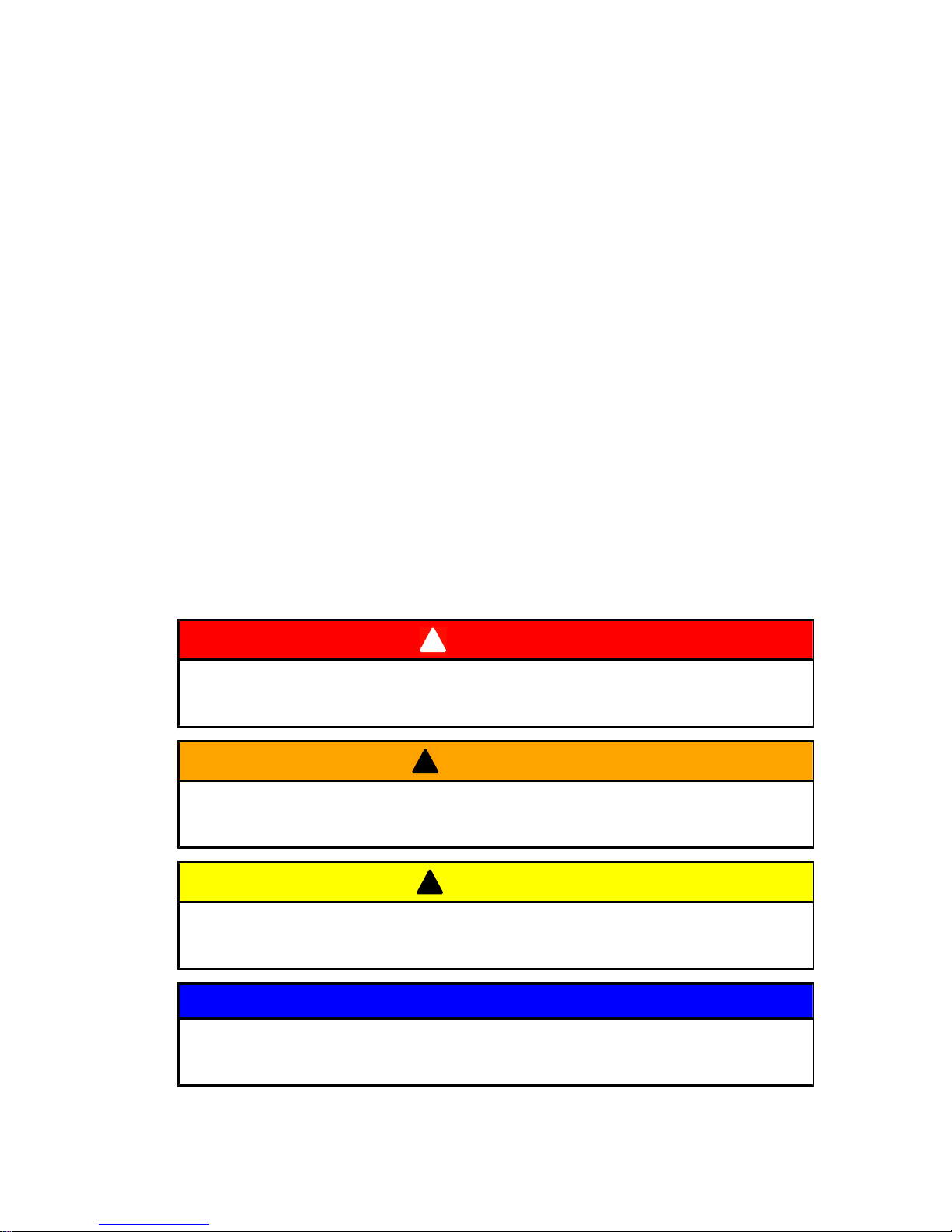
This manual as well as safety labels posted on the outboard use
the following safety alerts to draw your attention to special safety
instructions that should be followed.
!
DANGER
Indicates a hazardous situation which, if not avoided, will result
in death or serious injury.
!
WARNING
Indicates a hazardous situation which, if not avoided, could result
in death or serious injury.
!
CAUTION
Indicates a hazardous situation which, if not avoided, could result
in minor or moderate injury.
NOTICE
Indicates a situation which, if not avoided, could result in engine
or major component failure.
Page 22
GENERAL INFORMATION
14
Boat Horsepower Capacity
!
WARNING
Exceeding the boat's maximum horsepower rating can cause
serious injury or death. Overpowering the boat can affect boat
control and flotation characteristics or break the transom. Do not
install an engine that exceeds the boat's maximum power rating.
Do not overpower or overload your boat. Most boats will carry a
required capacity plate indicating the maximum acceptable power
and load as determined by the manufacturer following certain
federal guidelines. If in doubt, contact your dealer or the boat
manufacturer.
U.S. COAST GUARD CAP ACITY
MAXIMUM HORSEPOWER XXX
MAXIMUM PERSON
CAPACITY (POUNDS) XXX
MAXIMUM WEIGHT
CAPACITY XXX
26777
High‑Speed and High‑Performance Boat Operation
If your outboard is to be used on a high speed or high performance
boat with which you are unfamiliar, we recommend that you never
operate it at its high speed capability without first requesting an
initial orientation and familiarization demonstration ride with your
dealer or an operator experienced with your boat/outboard
combination. For additional information, obtain a copy of our
Hi‑Performance Boat Operation booklet from your dealer,
distributor, or Mercury Marine.
Outboard Remote Control Models
The outboard must be equipped with a Mercury remote control
designed for digital throttle and shift. Start‑in‑gear protection is
provided by the remote control system.
Page 23
GENERAL INFORMATION
15
Lanyard Stop Switch
The purpose of a lanyard stop switch is to turn off the engine when
the operator moves far enough away from the operator's position
(as in accidental ejection from the operator's position) to activate
the switch. Tiller handle outboards and some remote control units
are equipped with a lanyard stop switch. A lanyard stop switch can
be installed as an accessory ‑ generally on the dashboard or side
adjacent to the operator's position.
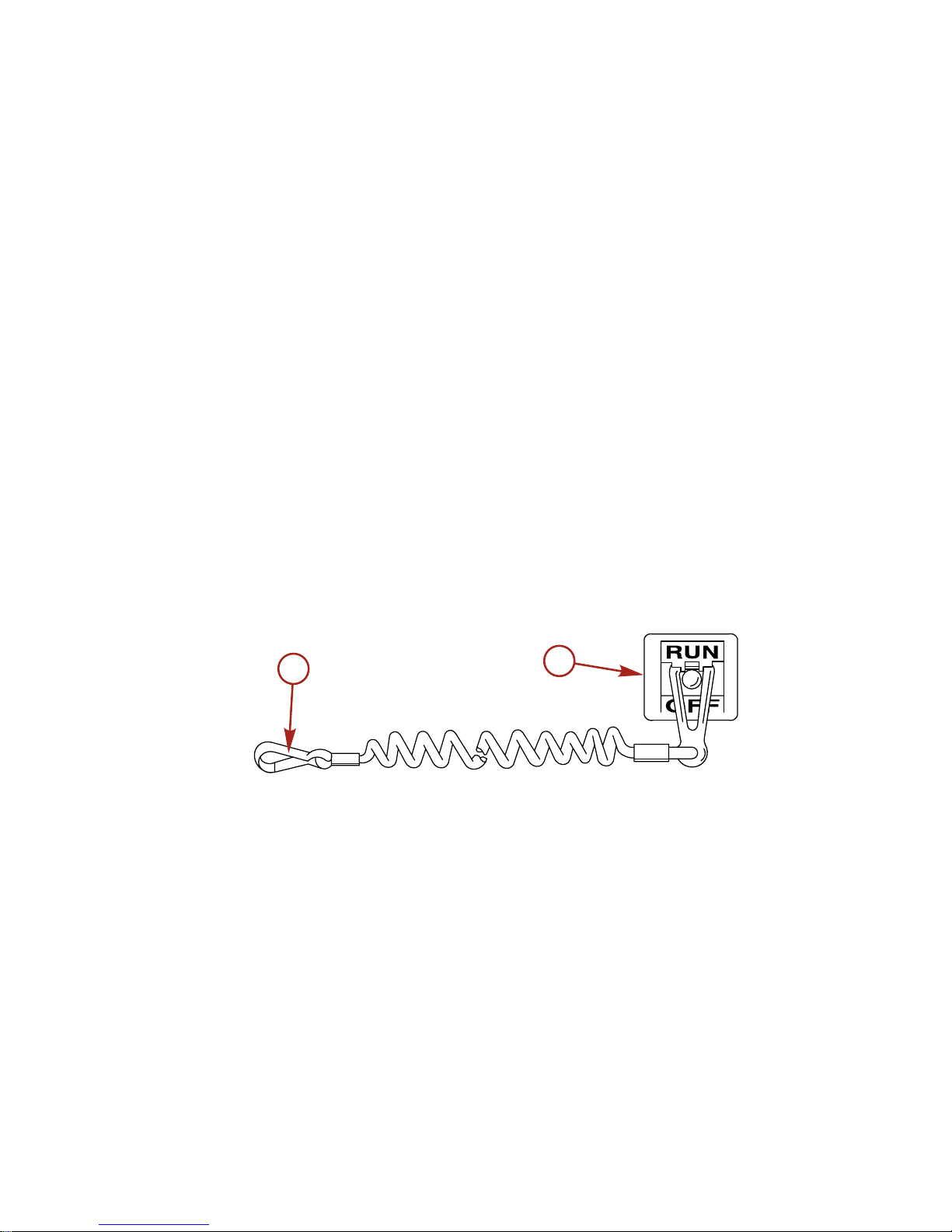
The lanyard is a cord usually 122 ‑ 152 cm (4 ‑ 5 feet) in length
when stretched out, with an element on one end made to be
inserted into the switch and a snap on the other end for attaching
to the operator. The lanyard is coiled to make its at‑rest condition
as short as possible to minimize the likelihood of lanyard
entanglement with nearby objects. Its stretched‑out length is made
to minimize the likelihood of accidental activation should the
operator choose to move around in an area close to the normal
operator's position. If it is desired to have a shorter lanyard, wrap
the lanyard around the operator's wrist or leg, or tie a knot in the
lanyard.
21629
a
b
a - Lanyard cord b - Lanyard stop switch
Read the following Safety Information before proceeding.
Page 24
GENERAL INFORMATION
16
Important Safety Information: The purpose of a lanyard stop switch
is to stop the engine when the operator moves far enough away
from the operator's position to activate the switch. This would occur
if the operator accidentally falls overboard or moves within the boat
a sufficient distance from the operator's position. Falling overboard
and accidental ejections are more likely to occur in certain types
of boats such as low sided inflatables, bass boats, high
performance boats, and light, sensitive handling fishing boats
operated by a hand tiller. Falling overboard and accidental
ejections are also likely to occur as a result of poor operating
practices such as sitting on the back of the seat or gunwale at
planing speeds, standing at planing speeds, sitting on elevated
fishing boat decks, operating at planing speeds in shallow or
obstacle infested waters, releasing your grip on a steering wheel
or tiller handle that is pulling in one direction, drinking alcohol or
consuming drugs, or daring high speed boat maneuvers.
While activation of the lanyard stop switch will stop the engine
immediately, a boat will continue to coast for some distance
depending upon the velocity and degree of any turn at shut down.
However, the boat will not complete a full circle. While the boat is
coasting, it can cause injury to anyone in the boat's path as
seriously as the boat would when under power.
We strongly recommend that other occupants be instructed on
proper starting and operating procedures should they be required
to operate the engine in an emergency (e.g. if the operator is
accidentally ejected).
!
WARNING
If the operator falls out of the boat, stop the engine immediately
to reduce the possibility of serious injury or death from being
struck by the boat. Always properly connect the operator to the
stop switch using a lanyard.
!
WARNING
Avoid serious injury or death from deceleration forces resulting
from accidental or unintended stop switch activation. The boat
operator should never leave the operator's station without first
disconnecting the stop switch lanyard from the operator.
Page 25
GENERAL INFORMATION
17
Accidental or unintended activation of the switch during normal
operation is also a possibility. This could cause any, or all, of the
following potentially hazardous situations:
• Occupants could be thrown forward due to unexpected loss
of forward motion ‑ a particular concern for passengers in the
front of the boat who could be ejected over the bow and
possibly struck by the gearcase or propeller.
• Loss of power and directional control in heavy seas, strong
current or high winds.
• Loss of control when docking.
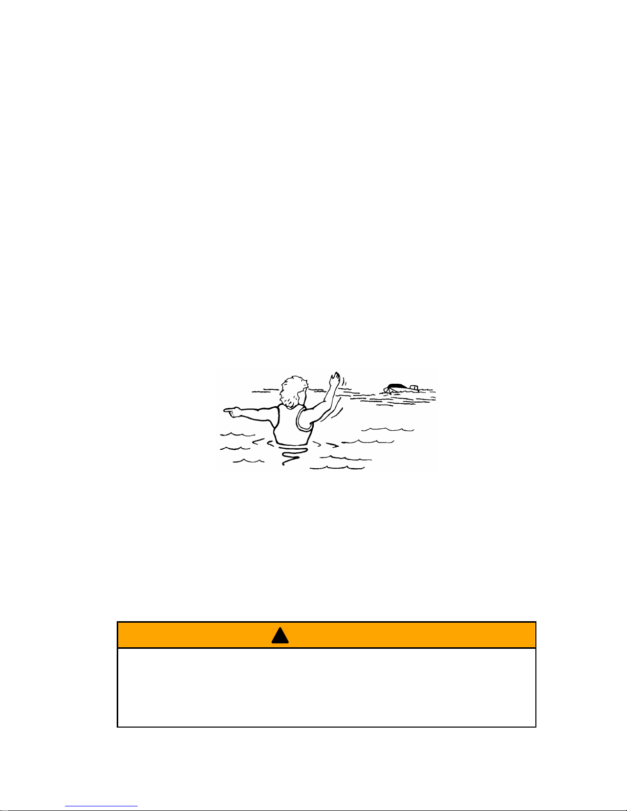
Protecting People In The Water
WHILE YOU ARE CRUISING
It is very difficult for a person standing or floating in the water to
take quick action to avoid a boat heading in his/her direction, even
at slow speed.
21604
Always slow down and exercise extreme caution any time you are
boating in an area where there might be people in the water.
Whenever a boat is moving (coasting) and the outboard gear shift
is in neutral position, there is sufficient force by the water on the
propeller to cause the propeller to rotate. This neutral propeller
rotation can cause serious injury.
WHILE BOAT IS STATIONARY
!
WARNING
A spinning propeller, a moving boat, or any solid device attached
to the boat can cause serious injury or death to swimmers. Stop
the engine immediately whenever anyone in the water is near
your boat.
Page 26
GENERAL INFORMATION
18
Shift outboard into neutral and shut off the engine before allowing
people to swim or be in the water near your boat.
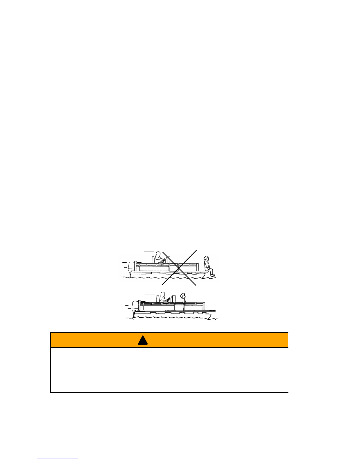
Passenger Safety Message ‑ Pontoon Boats And
Deck Boats
Whenever the boat is in motion, observe the location of all
passengers. Do not allow any passengers to stand or use seats
other than those designated for traveling faster than idle speed. A
sudden reduction in boat speed, such as plunging into a large wave
or wake, a sudden throttle reduction, or a sharp change of boat
direction, could throw them over the front of the boat. Falling over
the front of the boat between the two pontoons will position them
to be run over by the outboard.
BOATS HAVING AN OPEN FRONT DECK
No one should ever be on the deck in front of the fence while the
boat is in motion. Keep all passengers behind the front fence or
enclosure.
Persons on the front deck could easily be thrown overboard or
persons dangling their feet over the front edge could get their legs
caught by a wave and pulled into the water.
26782
!
WARNING
Sitting or standing in an area of the boat not designed for
passengers at speeds above idle can cause serious injury or
death. Stay back from the front end of deck boats or raised
platforms and remain seated while the boat is in motion.
Page 27
GENERAL INFORMATION
19
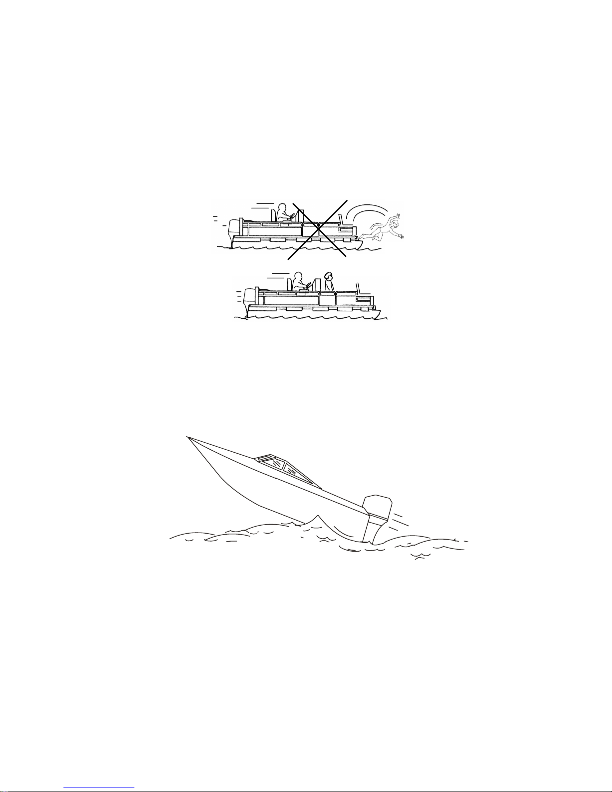
BOATS WITH FRONT MOUNTED, RAISED PEDESTAL
FISHING SEATS
Elevated fishing seats are not intended for use when the boat is
traveling faster than idle or trolling speed. Sit only in seats
designated for traveling at faster speeds.
Any unexpected, sudden reduction in boat speed could result in
the elevated passenger falling over the front of the boat.
26783
Wave And Wake Jumping
Operating recreational boats over waves and wake is a natural part
of boating. However, when this activity is done with sufficient speed
to force the boat hull partially or completely out of the water, certain
hazards arise, particularly when the boat re‑enters the water.
26784
The primary concern is the boat changing direction while in the
midst of the jump. In such case the landing may cause the boat to
veer violently in a new direction. Such a sharp change in direction
can cause occupants to be thrown out of their seats, or out of the
boat.
Page 28
GENERAL INFORMATION
20
!
WARNING
Wave or wake jumping can cause serious injury or death from
occupants being thrown within or out of the boat. Avoid wave or
wake jumping whenever possible.
There is another less common hazardous result from allowing your
boat to launch off a wave or wake. If the bow of your boat pitches
down far enough while airborne, upon water contact it may
penetrate under the water surface and submarine for an instant.
This will bring the boat to a nearly instantaneous stop and can send
the occupants flying forward. The boat may also steer sharply to
one side.
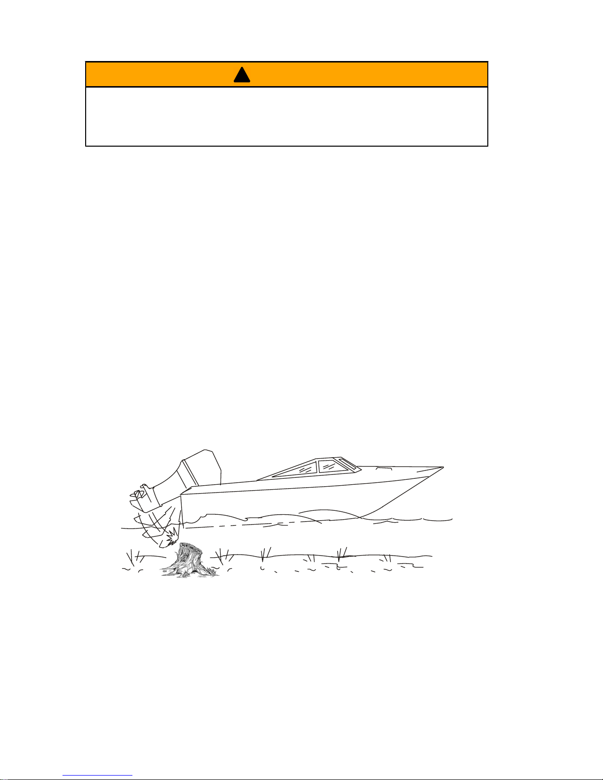
Impact With Underwater Hazards
Reduce speed and proceed with caution whenever you drive a
boat in shallow water areas, or in areas where you suspect
underwater obstacles may exist which could be struck by the
outboard or the boat bottom. The most important thing you can do
to help reduce injury or impact damage from striking a floating or
underwater object is to control the boat speed. Under these
conditions, boat speed should be kept to a minimum planing speed
of 24 to 40 km/h (15 to 25 MPH).
26785
Striking a floating or underwater object could result in an infinite
number of situations. Some of these situations could result in the
following:
• Part of the outboard or the entire outboard could break loose
and fly into the boat.
Page 29
GENERAL INFORMATION
21
• The boat could move suddenly in a new direction. Such a
sharp change in direction can cause occupants to be thrown
out of their seats or out of the boat.
• A rapid reduction in speed. This will cause occupants to be
thrown forward, or even out of the boat.
• Impact damage to the outboard and/or boat.
Keep in mind, the most important thing you can do to help reduce
injury or impact damage during an impact is control the boat speed.
Boat speed should be kept to a minimum planing speed when
driving in waters known to have underwater obstacles.
After striking a submerged object, stop the engine as soon as
possible and inspect it for any broken or loose parts. If damage is
present or suspected, the outboard should be taken to an
authorized dealer for a thorough inspection and necessary repair.
The boat should also be checked for any hull fractures, transom
fractures, or water leaks.
Operating a damaged outboard could cause additional damage to
other parts of the outboard, or could affect control of the boat. If
continued running is necessary, do so at greatly reduced speeds.
!
WARNING
Operating a boat or engine with impact damage can result in
product damage, serious injury, or death. If the vessel
experiences any form of impact, have an authorized Mercury
Marine dealer inspect and repair the vessel or power package.
Exhaust Emissions
BE ALERT TO CARBON MONOXIDE POISONING
Carbon monoxide is present in the exhaust fumes of all internal
combustion engines. This includes the outboards, sterndrives and
inboard engines that propel boats, as well as the generators that
power various boat accessories. Carbon monoxide is a deadly gas
that is odorless, colorless and tasteless.
Early symptoms of carbon monoxide poisoning which should not
be confused with seasickness or intoxication, include headache,
dizziness, drowsiness, and nausea.
Page 30
GENERAL INFORMATION
22
!
WARNING
Carbon monoxide poisoning can lead to unconsciousness, brain
damage, or death. Keep the boat well ventilated while at rest or
underway and avoid prolonged exposure to carbon monoxide.
GOOD VENTILATION
Ventilate passenger area, open side curtains, or forward hatches
to remove fumes.
21622
Example of desired air flow through the boat
POOR VENTILATION
Under certain running and/or wind conditions, permanently
enclosed or canvas enclosed cabins or cockpits with insufficient
ventilation may draw in carbon monoxide. Install one or more
carbon monoxide detectors in your boat.
Although the occurrence is rare, on a very calm day, swimmers
and passengers in an enclosed area of a stationary boat that
contains or is near a running engine may be exposed to a
hazardous level of carbon monoxide.
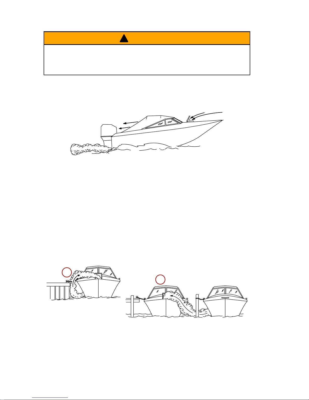
WHILE BOAT IS STATIONARY
21626
a
b
a - Running the engine when the boat is moored in a confined
space
b - Mooring close to another boat that has its engine running
Page 31

GENERAL INFORMATION
23
WHILE BOAT IS MOVING
a
b
21628
a - Running the boat with the trim angle of the bow too high
b - Running the boat with no forward hatches open
Selecting Accessories For Your Outboard
Genuine Mercury Precision or Quicksilver Accessories have been
specifically designed and tested for your outboard. These
accessories are available from Mercury Marine dealers.
IMPORTANT: Check with your dealer before installing
accessories. The misuse of approved accessories or the use of
non‑approved accessories can damage the product.
Some accessories not manufactured or sold by Mercury Marine
are not designed to be safely used with your outboard or outboard
operating system. Acquire and read the installation, operation, and
maintenance manuals for all your selected accessories.
Safe Boating Suggestions
In order to safely enjoy the waterways, familiarize yourself with
local and other governmental boating regulations and restrictions,
and consider the following suggestions.
Use flotation devices. Have an approved personal flotation device
of suitable size for each person aboard (it is the law) and have it
readily accessible.
Do not overload your boat. Most boats are rated and certified for
maximum load (weight) capacities (refer to your boat capacity
plate). If in doubt, contact your dealer or the boats manufacturer.
Perform safety checks and required maintenance. Follow a regular
schedule and ensure that all repairs are properly made.
Page 32

GENERAL INFORMATION
24
Know and obey all nautical rules and laws of the waterways. Boat
operators should complete a boating safety course. Courses are
offered in the U.S.A. by 1) The U.S. Coast Guard Auxiliary, 2) The
Power Squadron, 3) The Red Cross and 4) your state boating law
enforcement agency. Inquiries may be made to the Boating
Hotline, 1‑800‑368‑5647 or the Boat U.S. Foundation information
number 1‑800‑336‑BOAT.
Make sure everyone in the boat is properly seated. Do not allow
anyone to sit or ride on any part of the boat that was not intended
for such use. This includes the back of seats, gunwales, transom,
bow, decks, raised fishing seats, any rotating fishing seat; or
anywhere that an unexpected acceleration, sudden stopping,
unexpected loss of boat control, or sudden boat movement could
cause a person to be thrown overboard or into the boat.
Never be under the influence of alcohol or drugs while boating (it
is the law). Alcohol or drug use impairs your judgment and greatly
reduces your ability to react quickly.
Prepare other boat operators. Instruct at least one other person on
board in the basics of starting and operating the outboard, and boat
handling, in case the driver becomes disabled or falls overboard.
Passenger boarding. Stop the engine whenever passengers are
boarding, unloading, or are near the back (stern) of the boat. Just
shifting the outboard into neutral is not sufficient.
Be alert. The operator of the boat is responsible by law to maintain
a proper lookout by sight and hearing. The operator must have an
unobstructed view particularly to the front. No passengers, load,
or fishing seats should block the operators view when operating
the boat above idle speed.
Never drive your boat directly behind a water skier in case the skier
falls. As an example, your boat traveling at 40 km/h (25 MPH) will
overtake a fallen skier 61 m (200 ft.) in front of you in 5 seconds.
Watch fallen skiers. When using your boat for water skiing or
similar activities, always keep a fallen or down skier on the
operator's side of the boat while returning to assist the skier. The
operator should always have the down skier in sight and never
back up to the skier or anyone in the water.
Page 33

GENERAL INFORMATION
25
Report accidents. Boat operators are required by law to file a
Boating Accident Report with their state boating law enforcement
agency when their boat is involved in certain boating accidents. A
boating accident must be reported if 1) there is loss of life or
probable loss of life, 2) there is personal injury requiring medical
treatment beyond first aid, 3) there is damage to boats or other
property where the damage value exceeds $500.00 or 4) there is
complete loss of the boat. Seek further assistance from local law
enforcement.
Recording Serial Number
It is important to record this number for future reference. The serial
number is located on the outboard as shown.
a
XX
OTXXXXXX
XXXX
a
b
c
d
29688
a - Serial number
b - Model designation
c - Year manufactured
d - Certified Europe Insignia
(as applicable)
135/150/175/200 Specifications ‑ International
Models 135/150/175/200
Horsepower 135/150/175/200
Kilowatts 101/112/130/149
Full Throttle RPM Range
135 HP ‑ 5200‑6400
150/175/200 HP ‑ 5800‑6400
Idle Speed in Neutral Gear
1.
650 RPM
Number of Cylinders 4
Piston Displacement 1,731 cc (105.6 cid)
Cylinder Bore 82 mm (3.23 in.)
1. With engine fully warmed up.
Page 34

GENERAL INFORMATION
26
Models 135/150/175/200
Stroke 82 mm (3.23 in.)
Recommended Spark Plug NGK ILFR6G‑E
Spark Plug Gap 0.8 mm (0.0315 in.)
Spark Plug Hex Size 16 mm
Gear Ratio 2.08:1
Recommended Gasoline Refer to Fuel & Oil
Recommended Oil Refer to Fuel & Oil
Right Hand Rotation Gearcase
Lubricant Capacity
970 ml (32.8 fl. oz.)
Left Hand Rotation Gearcase
Lubricant Capacity
900 ml (30.4 fl. oz.)
Engine Oil Capacity With Oil
Filter Replacement
6.0 liters (6.3 qt.)
Battery Rating
1000 Marine Cranking Amps (MCA), 800 Cold
Cranking AMPS (CCA) or 180 Ampere Hour
(Ah)
Sound at Drivers Ear (ICOMIA
39/94)
83.2
Page 35

GENERAL INFORMATION
27
Component Identification
a
b
c
d
e
f
g
h
i
14811
j
a - Engine flush
b - Auxiliary tilt switch
c - Top cowl
d - Bottom cowl
e - Engine oil drain
f - Anti‑ventilation plate
g - Gearcase
h - Cooling water intake
holes
i - Transom brackets
j - Tilt lock level
Page 36

INSTALLATION
28
Installing Outboard
!
WARNING
Failure to correctly fasten the outboard could result in the
outboard propelling off the boat transom resulting in property
damage, serious injury, or death. Before operation, the outboard
must be correctly installed with the required mounting hardware.
Do not accelerate above idle speed in water that may contain
underwater obstacles if the outboard is not attached to the
transom correctly.
We strongly recommend that your dealer install your outboard and
related accessories to ensure proper installation and good
performance. If you install the outboard yourself, follow instructions
in the Outboard Installation Manual which is provided with the
outboard.
The outboard must be secured to the transom with the four
12.7 mm (1/2 in.) diameter mounting bolts and locknuts provided.
Install two bolts through the upper set of holes and two bolts
through the lower set of holes.
27746
Page 37

INSTALLATION
29
Propeller Selection
For best all around performance from your outboard/boat
combination, select a propeller that allows the engine to operate
in the upper half of the recommended full throttle RPM range with
the boat normally loaded (refer to General Information ‑
Specifications). This RPM range allows for better acceleration
while maintaining maximum boat speed.
22551
If changing conditions cause the RPM to drop below the
recommended range, such as warmer, more humid weather,
operation at higher elevations, increased boat load, or a dirty boat
bottom/gearcase, a propeller change or cleaning may be required
to maintain performance and ensure the outboards durability.
Check full‑throttle RPM, using an accurate tachometer, with the
engine trimmed out to a balanced‑steering condition (steering
effort equal in both directions) without causing the propeller to
break loose.
Page 38

TRANSPORTING
30
Trailering Boat/Outboard
Trailer your boat with the outboard tilted down in a vertical
operating position.
If additional ground clearance is required, the outboard should be
tilted up using an accessory outboard support device. Refer to your
local dealer for recommendations. Additional clearance may be
required for railroad crossings, driveways and trailer bouncing.
14825
IMPORTANT: Do not rely on the power trim/tilt system or tilt
support lever to maintain proper ground clearance for trailering.
The outboard tilt support lever is not intended to support the
outboard for trailering.
Shift the outboard to forward gear. This prevents the propeller from
spinning freely.
Page 39

FUEL AND OIL
31
Fuel Recommendations
IMPORTANT: Use of improper gasoline can damage your
engine. Engine damage resulting from the use of improper
gasoline is considered misuse of the engine, and damage
caused thereby will not be covered under the limited warranty.
FUEL RATINGS
Mercury Marine engines will operate satisfactorily when using a
major brand of unleaded gasoline meeting the following
specifications:
USA and Canada ‑ having a posted pump Octane Rating of 87 (R
+M)/2 minimum. Premium gasoline [92 (R+M)/2 Octane] is also
acceptable. Do NOT use leaded gasoline.
Outside USA and Canada ‑ having a posted pump Octane Rating
of 90 RON minimum. Premium gasoline (98 RON) is also
acceptable. Do not use leaded gasoline.
USING REFORMULATED (OXYGENATED) GASOLINES
(USA ONLY)
This type of gasoline is required in certain areas of the USA. The
2 types of oxygenates used in these fuels are Alcohol (Ethanol) or
Ether (MTBE or ETBE). If Ethanol is the oxygenate that is used in
the gasoline in your area, refer to Gasolines Containing Alcohol.
These Reformulated Gasolines are acceptable for use in your
Mercury Marine engine.
GASOLINES CONTAINING ALCOHOL
If the gasoline in your area contains either methanol (methyl
alcohol) or ethanol (ethyl alcohol), you should be aware of certain
adverse effects that can occur. These adverse effects are more
severe with methanol. Increasing the percentage of alcohol in the
fuel can also worsen these adverse effects.
Some of these adverse effects are caused because the alcohol in
the gasoline can absorb moisture from the air, resulting in a
separation of the water/alcohol from the gasoline in the fuel tank.
Page 40

FUEL AND OIL
32
The fuel system components on your Mercury Marine engine will
withstand up to 10% alcohol content in the gasoline. We do not
know what percentage your boat's fuel system will withstand.
Contact your boat manufacturer for specific recommendations on
the boat's fuel system components (fuel tanks, fuel lines, and
fittings). Be aware that gasolines containing alcohol may cause
increased:
• Corrosion of metal parts
• Deterioration of rubber or plastic parts
• Fuel permeation through rubber fuel lines
• Starting and operating difficulties
!
WARNING
Fuel leakage is a fire or explosion hazard, which can cause
serious injury or death. Periodically inspect all fuel system
components for leaks, softening, hardening, swelling, or
corrosion, particularly after storage. Any sign of leakage or
deterioration requires replacement before further engine
operation.
Because of possible adverse effects of alcohol in gasoline, it is
recommended that only alcohol‑free gasoline be used where
possible. If only fuel containing alcohol is available, or if the
presence of alcohol is unknown, increased inspection frequency
for leaks and abnormalities is required.
IMPORTANT: When operating a Mercury Marine engine on
gasoline containing alcohol, storage of gasoline in the fuel tank for
long periods should be avoided. Long periods of storage, common
to boats, create unique problems. In cars, alcohol‑blend fuels
normally are consumed before they can absorb enough moisture
to cause trouble, but boats often sit idle long enough for phase
separation to take place. In addition, internal corrosion may take
place during storage if alcohol has washed protective oil films from
internal components.
Page 41

FUEL AND OIL
33
Filling Fuel Tank
!
WARNING
Avoid serious injury or death from a gasoline fire or explosion.
Use caution when filling fuel tanks. Always stop the engine and
do not smoke or allow open flames or sparks in the area while
filling fuel tanks.
Fill fuel tanks outdoors away from heat, sparks, and open flames.
Remove portable fuel tanks from boat to refill them.
Always stop engine before refilling tanks.
Do not completely fill the fuel tanks. Leave approximately 10% of
the tank volume unfilled. Fuel will expand in volume as its
temperature rises and can leak under pressure if the tank is
completely filled.
PORTABLE FUEL TANK PLACEMENT IN THE BOAT
Place the fuel tank in the boat so the vent is higher than the fuel
level under normal boat operating conditions.
Engine Oil Recommendations
Mercury Verado NMMA FC‑W certified synthetic blend 25W‑50
multi‑viscosity 4‑Stroke Outboard Oil is recommended for general,
all‑temperature use. As an optional choice, Mercury or Quicksilver
NMMA FC‑W certified synthetic 25W‑40 multi‑viscosity 4‑Stroke
Outboard Oil may be used. If the recommended Mercury or
Quicksilver NMMA FC‑W certified oils are not available, a major
brand of NMMA FC‑W certified 4‑stroke outboard oil of similar
viscosity may be used.
Page 42

FUEL AND OIL
34
IMPORTANT: The use of non‑detergent oils, multi‑viscosity oils
(other than Mercury or Quicksilver NMMA FC‑W certified oil or a
major brand NMMA FC‑W certified oil), synthetic oils, low quality
oils or oils that contain solid additives are not recommended.
3
7
-
8
9
7
5
7
6
C
+100
+80
+60
+40
+20
0
+38
+120
+49
+27
+16
+4
-7
-18
F
29689
M
E
R
C
U
R
Y
V
E
R
A
D
O
E
N
G
I
N
E
O
I
L
Checking and Adding Engine Oil
IMPORTANT: Do not overfill. Tilt outboard out/up past vertical for
approximately one minute to allow trapped oil to drain back to the
oil sump. Tilt outboard to vertical (not tilted) position when checking
engine oil. For accurate readings, check oil only when engine is
cold or after engine has not run for at least an hour.
1. Before starting (cold engine) tilt outboard out/up past vertical
to allow trapped oil to drain back to the oil sump. Allow
outboard to remain tilted for approximately one minute.
2. Tilt outboard to vertical operating position.
3. Remove the top cowl. Refer to Maintenance - Cowl Removal
And Installation.
4. Pull out the dipstick. Wipe the dipstick end with a clean rag or
towel and push it back in all the way.
5. Pull the dipstick back out again and observe the oil level. Oil
should be in the operating range (cross hatched region).
Page 43

FUEL AND OIL
35
IMPORTANT: Do not try to fill the oil level to the top of the
operating range (cross hatched region). Oil level is correct as long
as it appears in the operating range (cross hatched region).
14784
a
a - Oil level operating range
6. If the oil level is below the operating range (cross hatched
region), remove the oil filler cap and add approximately
500 ml (16 oz.) of specified outboard motor oil. Allow a few
minutes for the added oil to drain to the oil sump and recheck
the dipstick. Repeat the process until oil level is on the
operating range (cross hatched region). Do not try to fill to the
upper end of the operation range (cross hatched region).
14770
Page 44

FUEL AND OIL
36
IMPORTANT: Inspect oil for signs of contamination. Oil
contaminated with water will have a milky color to it; oil
contaminated with fuel will have a strong fuel smell. If
contaminated oil is noticed, have the engine checked by your
dealer.
7. Push the dipstick back in all the way.
8. Reinstall the oil fill cap hand tight.
9. Reinstall top cowl.
Page 45
FEATURES AND CONTROLS
37
Panel Mount Control Features and Operation
1. Operation of shift and throttle is controlled by the movement
of the control handle. Push the control handle forward from
neutral to the first detent for forward gear. Continue pushing
forward to increase speed. Pull the control handle back from
neutral to the first detent for reverse gear. Continue pulling
back to increase speed.
F
N
R
3413
2. Shift lock ‑ Pressing the shift lock allows the engine to shift.
The shift lock must always be pressed when moving the
control handle out of the neutral position.
3428
Page 46

FEATURES AND CONTROLS
38
3. Trim switch (if equipped) ‑ Pressing the trim switch allows the
engine to trim up or down.
5152
4. Throttle only button ‑ Allows the boat operator to increase
engine RPM for warm‑up, without shifting the engine into gear.
To engage throttle only, move the control handle into the
neutral position. Press the throttle only button while moving
the control handle ahead to the forward detent. The horn
indicates throttle only is engaged. Advance throttle to increase
engine RPM. To disengage, return control handle to neutral
position. Engine RPM is limited to prevent engine damage.
3416
Page 47

FEATURES AND CONTROLS
39
5. Stop/start button ‑ Allows the boat operator to start or stop the
engine without using the ignition key. The ignition key must be
in the "ON" position to start the engine.
3414
6. Lanyard stop switch ‑ Turns the ignition off whenever the
operator (when attached to the lanyard) moves far enough
away from the operator's position to activate the switch.
a
22964
7. Control handle tension adjustment screw ‑ This screw can be
adjusted to increase or decrease the tension on the control
handle (cover must be removed). This will help prevent
unwanted motion of the handle in rough water. Turn screw
clockwise to increase tension and counterclockwise to
decrease tension. Adjust to tension desired.
Page 48

FEATURES AND CONTROLS
40
8. Detent tension adjustment screw ‑ This screw can be adjusted
to increase or decrease the effort to move control handle out
of detent positions (cover must be removed). Turning screw
clockwise will increase tension. Adjust to tension desired.
5171
+
-
a
b
a - Detent tension
adjustment screw
b - Control handle tension
adjustment screw
Single Handle Console Control Features and
Operation
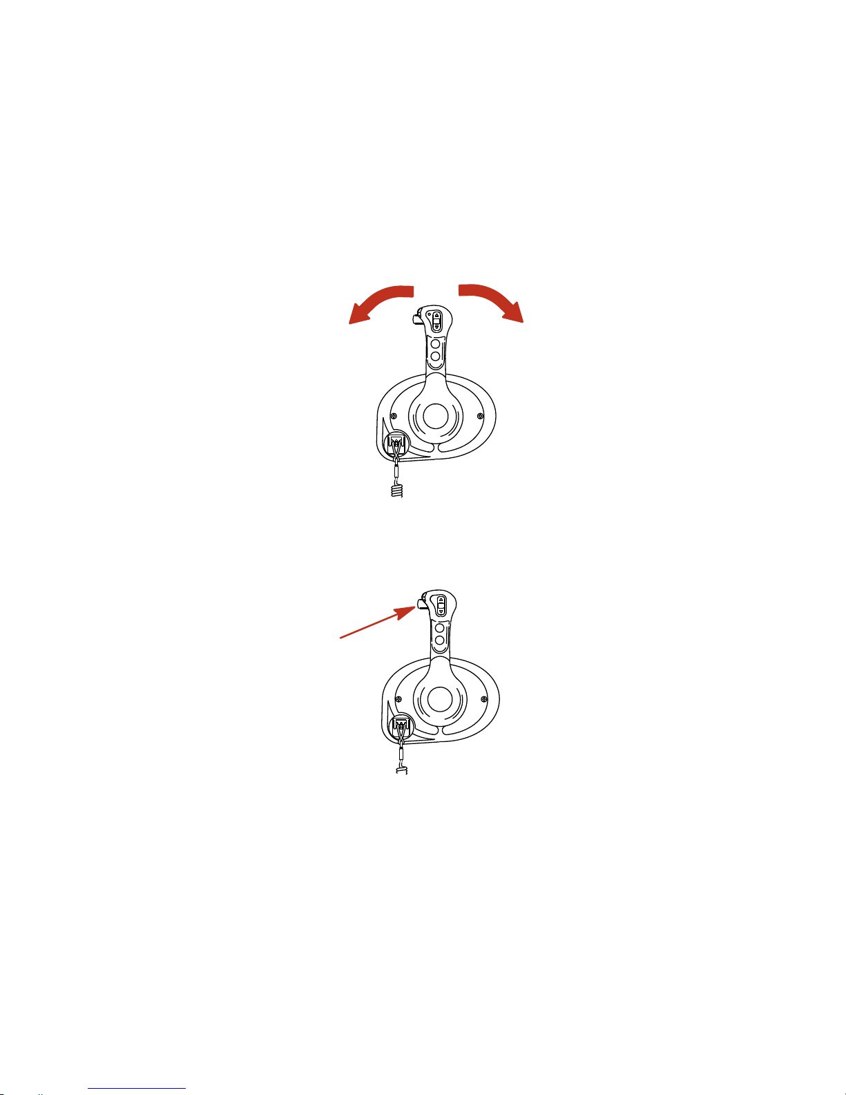
1. Operation of shift and throttle is controlled by the movement
of the control handle. Push the control handle forward from
neutral to the first detent for forward gear. Continue pushing
forward to increase speed. Pull the control handle back from
neutral to the first detent for reverse gear. Continue pushing
back to increase speed.
F
N
R
3417
Page 49

FEATURES AND CONTROLS
41
2. Trim switch (if equipped) ‑ Pressing the trim switch allows the
engine to trim up or down.
5185
3. Control handle tension adjustment screw ‑ This screw can be
adjusted to increase or decrease the tension on the control
handle (cover must be removed). This will help prevent
unwanted motion of the remote control handle in rough water.
Turn the screw clockwise to increase tension and
counterclockwise to decrease tension. Adjust to the desired
tension.
4. Detent tension adjustment screw ‑ This screw can be adjusted
to increase or decrease the effort to move control handle out
of detent positions (cover must be removed). Turning the
screw clockwise will increase tension. Adjust to the desired
tension.
a
b
28556
a - Detent tension
adjustment screw
b - Control handle tension
adjustment screw
5. Arrow trackpad ‑ Navigates through the System View
on‑screen function messages.
Page 50

FEATURES AND CONTROLS
42
6. Select button ‑ Selects the System View on‑screen options
and confirm data entries. Holding the select button for two
seconds will pause the slide show if selected in Favorites.
Holding the select button for three seconds will activate the
reset data function (except when in the slide show function).
Holding the select button for five seconds or more will bring
up the Home page.
7. Neutral LED ‑ The neutral LED illuminates when engine is in
neutral gear position. It also flashes when throttle only is
activated.
NOTE: Gear position is determined by sensing the position of the
shift actuator on the engine, not the position of the control handle.
8. Active LED ‑ The active LED illuminates to show the remote
control is active and ready for use.
Page 51

FEATURES AND CONTROLS
43
9. Throttle only/station select button ‑ Allows the boat operator
to increase engine RPM for warm‑up, without shifting the
engine into gear. To engage throttle only, move the control
handle into the neutral position. Press the throttle only button
while moving the control handle ahead to the forward detent.
The horn will sound once and the neutral light will start
flashing. The horn will sound twice when throttle only is
engaged. Advance throttle to increase engine RPM. To
disengage, return control handle to neutral position and press
the throttle only button. Engine RPM is limited to prevent
engine damage. Pressing the station select button at an
inactive helm initiates a helm transfer. Refer to Helm
Transfer.
d
b
a
c
e
5187
a - Neutral LED
b - Select button
c - Arrow trackpad
d - Throttle only/station
select button
e - Active LED
HELM TRANSFER
!
WARNING
Avoid serious injury or death from loss of boat control. The boat
operator should never leave the active station while engine is in
gear. Helm transfer should only be attempted while both stations
are manned. One‑person helm transfer should only be
performed while engine is in neutral.
NOTE: Idle position is preferred when doing a helm transfer. If
conditions do not allow the remote control to be placed at idle
position, a helm transfer can be done while in gear.
Page 52

FEATURES AND CONTROLS
44
NOTE: The active light on the remote control will be illuminated at
the helm that is in control of the engine.
The helm transfer function allows the boat operator to select which
helm is in control of engine operation. Pressing the throttle only/
station select button two times allows engine control to be
transferred to a new helm. When a helm transfer is initiated, the
control will automatically start adjusting engine RPM and gear
position to match the control handle setting at the new helm. Adjust
the control handles to the desired throttle and gear position.
NOTE: There is a 10 second time frame to complete a helm
transfer. If the helm transfer is not completed, the action will be
cancelled and a double beep will sound. Pressing the throttle only/
station select button again will re‑initiate a helm transfer.
1. Place active remote control lever to idle position.
2. Proceed to the inactive helm and position remote control lever
to the idle position.
3. Press throttle only/station select button two times. The
"ACTIVE" light will illuminate to indicate the remote control is
in control of the engine.
ACTIVE
STATION SELECT
ACTIVE
SYNC
STATION SELECT
THROTTLE
ONLY
THROTTLE
ONLY
22753
a
b
a
b
a - Active light b - Throttle only/station
select button
4. The "ACTIVE" light will switch off at the original helm.
Page 53

FEATURES AND CONTROLS
45
Synchronizing Helms Prior To Helm Transfer
Pressing the throttle only/station select button one time allows the
boat operator 10 seconds to match up the control handle setting
at the new station with the handle setting that is at the old (to be
inactive) station. If the handle is not matched, the neutral light will
flash. The light blinks faster as the handle is nearing match
position. Once the light stays on continuously, the handle is
matched and the throttle only/station select button can be pressed
again to complete the transfer. This completes the transfer
process, and give control to the new station. If the helm transfer is
not completed within 10 seconds, the helm transfer is cancelled.
Slim Binnacle Control Features and Operation
1. Operation of shift and throttle is controlled by the movement
of the control handle. Push the control handle forward from
neutral to the first detent for forward gear. Continue pushing
forward to increase speed. Pull the control handle back from
neutral to the first detent for reverse gear. Continue pushing
back to increase speed.
F
N
R
12871
Page 54

FEATURES AND CONTROLS
46
2. Trim switch (if equipped) ‑ Pressing the trim switch allows the
engine to trim up or down.
12874
a
a - Trim switch
3. Control handle tension adjustment screw ‑ This screw can be
adjusted to increase or decrease the tension on the control
handle (cover must be removed). This will help prevent
unwanted motion of the remote control handle in rough water.
Turn the screw clockwise to increase tension and
counterclockwise to decrease tension. Adjust to the desired
tension.
Page 55

FEATURES AND CONTROLS
47
4. Detent tension adjustment screw ‑ This screw can be adjusted
to increase or decrease the effort to move control handle out
of detent positions (cover must be removed). Turning the
screw clockwise will increase tension. Adjust to the desired
tension.
a
b
28556
a - Detent tension
adjustment screw
b - Control handle tension
adjustment screw
5. Start/stop button ‑ Allows the boat operator to start or stop the
engine without using the ignition key.
6. Neutral LED ‑ The neutral LED illuminates when engine is in
neutral gear position. It also flashes when throttle only is
activated.
NOTE: Gear position is determined by sensing the position of the
shift actuator on the engine, not the position of the control handle.
7. Active LED ‑ The active LED illuminates to show the remote
control is active and ready for use.
Page 56

FEATURES AND CONTROLS
48
8. Throttle only/station select button ‑ Allows the boat operator
to increase engine RPM for warm‑up, without shifting the
engine into gear. To engage throttle only, move the control
handle into the neutral position. Press the throttle only button
while moving the control handle ahead to the forward detent.
The horn will sound once and the neutral light will start
flashing. The horn will sound twice when throttle only is
engaged. Advance throttle to increase engine RPM. To
disengage, return control handle to neutral position and press
the throttle only button. Engine RPM is limited to prevent
engine damage. Pressing the station select button at an
inactive helm initiates a helm transfer. Refer to Helm
Transfer.
START
STOP
22970
d
c
a
b
a - Start/stop button
b - Throttle only/station
select button
c - Neutral LED
d - Active LED
HELM TRANSFER
!
WARNING
Avoid serious injury or death from loss of boat control. The boat
operator should never leave the active station while engine is in
gear. Helm transfer should only be attempted while both stations
are manned. One‑person helm transfer should only be
performed while engine is in neutral.
NOTE: Idle position is preferred when doing a helm transfer. If
conditions do not allow the remote control to be placed at idle
position, a helm transfer can be done while in gear.
Page 57

FEATURES AND CONTROLS
49
NOTE: The active light on the remote control will be illuminated at
the helm that is in control of the engine.
The helm transfer function allows the boat operator to select which
helm is in control of engine operation. Pressing the throttle only/
station select button two times allows engine control to be
transferred to a new helm. When a helm transfer is initiated, the
control will automatically start adjusting engine RPM and gear
position to match the control handle setting at the new helm. Adjust
the control handles to the desired throttle and gear position.
NOTE: There is a 10 second time frame to complete a helm
transfer. If the helm transfer is not completed, the action will be
cancelled and a double beep will sound. Pressing the throttle only/
station select button again will re‑initiate a helm transfer.
1. Place the active remote control lever to idle position.
2. Proceed to the inactive helm and position remote control lever
to the idle position.
3. Press throttle only/station select button two times. The
"ACTIVE" light will illuminate to indicate the remote control is
in control of the engine.
START
STOP
22608
a
b
a - Active light b - Throttle only/station
select button
4. The "ACTIVE" light will switch off at the original helm.
Synchronizing Helms Prior To Helm Transfer
Pressing the throttle only/station select button one time allows the
boat operator 10 seconds to match up the control handle setting
at the new station with the handle setting that is at the old (to be
inactive) station. If the handle is not matched, the neutral light will
flash. The light blinks faster as the handle is nearing match
position. Once the light stays on continuously, the handle is
matched and the throttle only/station select button can be pressed
again to complete the transfer. This completes the transfer
process, and give control to the new station. If the helm transfer is
not completed within 10 seconds, the helm transfer is cancelled.
Page 58

FEATURES AND CONTROLS
50
Dual Handle Console Control Features and
Operation
1. Operation of shift and throttle is controlled by the movement
of the control handle. Push the control handle forward from
neutral to the first detent for forward gear. Continue pushing
forward to increase speed. Pull the control handle back from
neutral to the first detent for reverse gear. Continue pulling
back to increase speed.
F
N
R
3417
2. Trim switch (if equipped) ‑ Pressing the trim switch allows the
engine to trim up or down.
5269
3. Control handle tension adjustment screw ‑ This screw can be
adjusted to increase or decrease the tension on the control
handle (cover must be removed). This will help prevent
unwanted motion of the handle in rough water. Turn the screw
clockwise to increase tension and counterclockwise to
decrease tension. Adjust to the desired tension.
Page 59

FEATURES AND CONTROLS
51
4. Detent tension adjustment screw ‑ This screw can be adjusted
to increase or decrease the effort to move control handle out
of detent positions (cover must be removed). Turning screw
clockwise will increase tension. Adjust to the desired tension.
a
b
28556
a - Detent tension
adjustment screw
b - Control handle friction
adjustment screw
5. Throttle only/station select button ‑ Allows the boat operator
to increase engine RPM for warm‑up, without shifting the
engine into gear. To engage throttle only, move the control
handle into the neutral position. Press the throttle only button
while moving the control handle ahead to the forward detent.
The horn will sound once and the neutral light will start
flashing. The horn will sound twice when throttle only is
engaged. Advance throttle to increase engine RPM. To
disengage, return control handle to neutral position and press
the throttle only button. Engine RPM is limited to prevent
engine damage. Pressing the station select button at an
inactive helm initiates a helm transfer. Refer to Helm
Transfer.
6. Arrow trackpad ‑ Navigates through System View on‑screen
function messages.
7. Select button ‑ Selects System View on‑screen options and
confirms data entries. Holding the select button for two
seconds will pause the slide show if selected in Favorites.
Holding the select button for three seconds will activate the
reset data function (except when in the slide show function).
Holding the select button for five seconds or more will bring
up the Home page.
Page 60

FEATURES AND CONTROLS
52
8. Neutral LEDs ‑ The neutral LEDs illuminate when engines are
in neutral gear position. The lights will flash when in throttle
only mode.
NOTE: Gear position is determined by sensing the position of the
shift actuator on the engine, not the position of the control handle.
9. Active LED ‑ The active LED illuminates to show the remote
control is active and ready for use.
10.SYNC LED ‑ The SYNC LED illuminates when the RPM of the
two engines are being synchronized by the DTS system.
5270
ACTIVE
SYNC
THROTTLE
ONLY
STATION SELECT
a
b
c
d
e
f
a - Neutral LEDS
b - Select button
c - Arrow trackpad
d - SYNC LED
e - Throttle only/station
select button
f - Active LED
SYNCHRONIZING ENGINES
The auto synchronizing feature, when engaged, will automatically
adjust all engine speeds to match the speed of the starboard
engine.
Page 61

FEATURES AND CONTROLS
53
Engine auto synchronization will automatically engage when
engine speed is over 900 RPM for two seconds and remote control
handles are positioned within 10% of each other. The "SYNC" light
will turn on when the engines are synchronized. Auto
synchronization will stay engaged up to 95% throttle opening. To
disengage, move one or both control handles until they are more
than 10% apart, reduce engine speed below 900 RPM, or increase
engine speed beyond 95%.
22969
ACTIVE
SYNC
STATION SELECT
THROTTLE
ONLY
HELM TRANSFER
!
WARNING
Avoid serious injury or death from loss of boat control. The boat
operator should never leave the active station while engine is in
gear. Helm transfer should only be attempted while both stations
are manned. One‑person helm transfer should only be
performed while engine is in neutral.
NOTE: Idle position is preferred when doing a helm transfer. If
conditions do not allow the remote control to be placed at idle
position, a helm transfer can be done while in gear.
NOTE: The active light on the remote control will be illuminated at
the helm that is in control of the engine.
The helm transfer function allows the boat operator to select which
helm is in control of engine operation. Pressing the throttle only/
station select button two times allows engine control to be
transferred to a new helm. When a helm transfer is initiated, the
control will automatically start adjusting engine RPM and gear
position to match the control handle setting at the new helm. Adjust
the control handles to the desired throttle and gear position.
NOTE: There is a 10 second time frame to complete a helm
transfer. If the helm transfer is not completed, the action will be
cancelled and a double beep will sound. Pressing the throttle only/
station select button again will re‑initiate a helm transfer.
Page 62

FEATURES AND CONTROLS
54
1. Place active remote control lever to idle position.
2. Proceed to the inactive helm and position remote control lever
to the idle position.
3. Press throttle only/station select button two times. The
"ACTIVE" light will illuminate to indicate the remote control is
in control of the engine.
ACTIVE
STATION SELECT
ACTIVE
SYNC
STATION SELECT
THROTTLE
ONLY
THROTTLE
ONLY
22753
a
b
a
b
a - Active light b - Throttle only/station
select button
4. The "ACTIVE" light will switch off at the original helm.
Synchronizing Helms Prior To Helm Transfer
Pressing the throttle only/station select button one time allows the
boat operator 10 seconds to match up the control handle setting
at the new station with the handle setting that is at the old (to be
inactive) station. If the handle is not matched, the neutral light will
flash. The light blinks faster as the handle is nearing match
position. Once the light stays on continuously, the handle is
matched and the throttle only/station select button can be pressed
again to complete the transfer. This completes the transfer
process, and give control to the new station. If the helm transfer is
not completed within 10 seconds, the helm transfer is cancelled.
Page 63

FEATURES AND CONTROLS
55
Dual Handle Console Control with CAN Trackpad
Features and Operation
1. Operation of shift and throttle is controlled by the movement
of the control handle. Push the control handle forward from
neutral to the first detent for forward gear. Continue pushing
the handle forward to increase speed. Pull the control handle
back from neutral to the first detent for reverse gear. Continue
pulling the handle back to increase speed.
F
N
R
3417
2. Trim switch (if equipped) ‑ Pressing the trim switch allows the
engine to trim up and down.
N
E
U
T
R
A
L
SYNC
THROTTLE
ONLY
+
-
TROLL
TRANSFER
DOCK
1 LEVER
22132
3. Neutral lights ‑ The neutral lights illuminate when the engine
is in neutral gear position. The lights will flash when the engine
is in throttle only mode.
NOTE: Gear position is determined by the position of the shift
actuator on the engine, not the position of the control handle.
Page 64

FEATURES AND CONTROLS
56
4. Troll button ‑ Pressing the "TROLL" button activates troll
control. The troll control feature allows the boat operator to set
the engine speed for slow speed cruising or maneuvering. To
activate, move the control handles into forward detent and
press the button. Use the ‑ or + buttons to decrease or
increase speed, up to a maximum of 1000 RPM. If troll control
is set at a desired speed and then shut off, the system
remembers the set speed and will return to that speed when
re‑engaged. To turn off the troll control press the "TROLL"
button, move the throttle to a different speed, or shift the
engine into neutral.
5. Transfer button ‑ Pressing the "TRANSFER" button allows
engine operation to be transferred from a different helm. Refer
to Helm Transfer.
6. Dock button ‑ Pressing the "DOCK" button initiates docking
mode. Docking mode reduces throttle capacity to
approximately 50% of normal throttle. To turn off docking
mode, shift the engine into neutral and press the "DOCK"
button.
7. Throttle only button ‑ Allows the boat operator to increase
engine RPM for warm‑up, without shifting the engine into gear.
To engage throttle only, move the control handle into the
neutral position. Press the throttle only button and move the
control handle ahead to the forward detent. The horn will
sound once and the neutral light will start flashing. The horn
will sound twice when throttle only is engaged. Advance
throttle to increase engine RPM. To disengage, return control
handle to neutral position and press the throttle only button.
Engine RPM is limited to prevent engine damage.
8. 1 lever button ‑ Pressing the "1 LEVER" button initiates single
lever mode. Single lever mode enables the throttle and shift
functions of both engines to be controlled by the port control
handle. To turn off single lever mode, shift the engine into
neutral and press the "1 LEVER" button.
Page 65

FEATURES AND CONTROLS
57
9. Sync button ‑ Pressing the "SYNC" button turns off or on the
auto synchronization feature. Refer to Synchronizing
Engines.
N
E
U
T
R
A
L
22133
SYNC
1 LEVER
NEUTRAL
TROLL
THROTTLE
ONLY
DOCK
TRANSFER
+
-
a
b
c
e
g
f
d
a - Neutral LEDS
b - Troll button
c - Transfer button
d - Dock button
e - Throttle only
f - 1 lever button
g - Sync button
10.Control handle tension adjustment screw ‑ This screw can be
adjusted to increase or decrease the tension on the control
handle (cover must be removed). This will help prevent
unwanted motion of the handle in rough water. Turn the screw
clockwise to increase tension and counterclockwise to
decrease tension. Adjust to tension desired.
Page 66

FEATURES AND CONTROLS
58
11.Detent tension adjustment screw ‑ This screw can be adjusted
to increase or decrease the effort to move control handle out
of detent positions (cover must be removed). Turning the
screw clockwise will increase tension. Adjust to tension
desired.
a
b
28556
a - Detent tension
adjustment screw
b - Control handle tension
adjustment screw
SYNCHRONIZING ENGINES
The auto synchronizing feature, when engaged, will automatically
adjust all engine speeds to match the speed of the starboard
engine.
Press the "SYNC" button on the CAN trackpad to turn auto
synchronization on or off. When the sync LED is yellow, the
"SYNC" button has been pressed, but the conditions are not right
for auto synchronization to engage. When the sync LED turns red,
engine synchronization has been engaged. The engines will
remain synchronized as long as engine speed is over 900 RPM for
two seconds, remote control handles are positioned within 10% of
each other, and the engines are below 95% throttle opening.
Page 67

FEATURES AND CONTROLS
59
To disengage the auto synchronization feature, press the "SYNC"
button.
SYNC
1 LEVER
NEUTRAL
TROLL
THROTTLE
ONLY
DOCK
TRANSFER
+
-
22590
HELM TRANSFER
!
WARNING
Avoid serious injury or death from loss of boat control. The boat
operator should never leave the active station while engine is in
gear. Helm transfer should only be attempted while both stations
are manned. One‑person helm transfer should only be
performed while engine is in neutral.
NOTE: Neutral position is preferred when doing a station transfer.
If conditions do not allow the remote control to be placed in the
neutral position, a helm transfer can be done while in gear.
The helm transfer function allows the boat operator to select which
helm is in control of engine operation. Pressing the "TRANSFER"
button two times allows engine control to be transferred to a new
helm. When a helm transfer is initiated, the control will
automatically start adjusting engine RPM and gear position to
match the control handle setting at the new helm. Adjust the control
handles to the desired throttle and gear position.
Once the "TRANSFER" button is pressed, the transfer LED will
light up and one beep will sound. Press the "TRANSFER" button
again to complete the helm transformation. When helm
transformation is complete, another beep will sound and the
transfer LED will turn off.
Page 68

FEATURES AND CONTROLS
60
NOTE: There is a 10 second time frame to complete a helm
transfer. If the helm transfer is not completed, the action will be
cancelled and a double beep will sound. Pressing the
"TRANSFER" button again will re‑initiate a helm transfer.
SYNC
1 LEVER
NEUTRAL
TROLL
THROTTLE
ONLY
DOCK
TRANSFER
+
-
22593
Synchronizing Helms Prior To Transfer
Pressing the "TRANSFER" button allows the boat operator 10
seconds to match up the control handle settings at the new helm
with the handle settings that are at the old (to be inactive) helm. If
the handles are not matched, the neutral lights will flash. The light
blinks faster as the handles are nearing match position. Once the
light stays on continuously, the handles are matched and the
button can be pressed again to complete the transfer. This
completes the transfer process, and gives control to the new
station. If the helm transfer is not completed within 10 seconds, the
action will be cancelled.
Shadow Mode Control Features and Operation
TRIPLE ENGINE THROTTLE AND SHIFT OPERATION
Movement of the handles on the remote control allows the boat
operator to control the engine throttle speed and gear shift
positions of all three engines.
The throttle and shift function is dependant on what engines are
running. Refer to the following table.
Page 69

FEATURES AND CONTROLS
61
Port Engine Center Engine Starboard Engine
Control Handle
Function
Running Running Running
Port engine throttle
and shift = controlled
by port control
handle
Starboard engine
throttle and shift =
controlled by
starboard control
handle
Center engine
throttle = average of
port and starboard
engines
Center engine shift =
neutral unless both
engines are in the
same gear
Running Running Off
Port and center
engine throttle and
shift = controlled by
port control handle
Off Running Running
Starboard and
center engine
throttle and shift =
controlled by
starboard control
handle
Running Off Running
Port engine throttle
and shift = controlled
by port control
handle
Starboard engine
throttle and shift =
controlled by
starboard control
handle
Running Off Off
Port engine throttle
and shift = controlled
by port control
handle
Page 70

FEATURES AND CONTROLS
62
Port Engine Center Engine Starboard Engine
Control Handle
Function
Off Off Running
Starboard engine
throttle and shift =
controlled by
starboard control
handle
Off (ignition key
switch turned on)
Running
Off (ignition key
switch turned on)
Center engine
throttle and shift =
neutral/idle unless
both control handles
are in the same gear
Turning off one of the outer engines while underway will cause the
center engine to go into forced neutral/idle. Operation to the center
engine can be restored by moving the control handle of the
functioning outer engine back into neutral position and then
re‑engaging. The center engine speed and gear shift will then be
controlled by the functioning outer engine.
Turning off the center engine while underway will have no effect
on the operation of the outer engines.
If a failure should occur while underway which causes one of the
outer engines into forced neutral/idle condition, the center engine
will also be forced to neutral/idle. Operation to the center engine
can be restored by moving the control handle of the functioning
outer engine back into neutral and then re‑engaging.
QUAD ENGINE THROTTLE AND SHIFT OPERATION
Movement of the handles on the remote control allows the boat
operator to control the engine throttle speed and gear shift
positions of all four engines.
The throttle and shift function is dependant on what engines are
running. Refer to the following table.
Page 71

FEATURES AND CONTROLS
63
Port Outer
Engine
Port Inner
Engine
Starboard
Inner Engine
Starboard
Outer Engine
Control Handle
Function
Running Running Running Running
Port inner and
outer engines
throttle and
shift =
controlled by
port control
handle
Starboard
inner and outer
engines throttle
and shift =
controlled by
starboard
control handle
Running Running Off Off
Port inner and
outer engine
throttle and
shift =
controlled by
port control
handle
Off Off Running Running
Starboard
inner and outer
engine throttle
and shift =
controlled by
starboard
control handle
Off (ignition
key switch
turned on)
Running Running Running
Port inner
engine throttle
and shift =
controlled by
port control
handle
Running Running Running
Off (ignition key
switch turned
on)
Starboard
inner engine
throttle and
shift =
controlled by
starboard
control handle
Page 72

FEATURES AND CONTROLS
64
Port Outer
Engine
Port Inner
Engine
Starboard
Inner Engine
Starboard
Outer Engine
Control Handle
Function
Off (ignition
key switch
turned off)
Running Running Running
Port inner
engine throttle
and shift =
controlled by
starboard
control handle
Running Running Running
Off (ignition key
switch turned
off)
Starboard
inner engine
throttle and
shift =
controlled by
port control
handle
Running Off Off Running
Port outer
engine throttle
and shift =
controlled by
port control
handle
Starboard
outer engine
throttle and
shift =
controlled by
starboard
control handle
Off (ignition
key switch
turned on)
Running Running
Off (ignition key
switch turned
on)
Port inner
engine throttle
and shift =
controlled by
port control
handle
Starboard
inner engine
throttle and
shift =
controlled by
starboard
control handle
Page 73

FEATURES AND CONTROLS
65
Turning off the starboard outer engine while underway will cause
the starboard inner engine to go into forced neutral/idle. Operation
to the inner engine can be restored by turning the starboard outer
engine ignition key to the on position and moving the starboard
control handle back into neutral position and then re‑engaging. The
inner engine speed and gear shift will then be controlled by the
starboard control handle.
Turning off the port outer engine while underway will cause the port
inner engine to go into forced neutral/idle. Operation to the inner
engine can be restored by turning the port outer engine ignition key
to the on position and moving the port control handle back into
neutral position and then re‑engaging. The inner engine speed and
gear shift will then be controlled by the port control handle.
Turning off one of the inner engines while underway will have no
effect on the operation of the outer engines.
If a failure should occur while underway which causes the
starboard outer engines into forced neutral/idle condition, the inner
starboard engine will also be forced to neutral/idle. Operation to
the inner engine can be restored by moving the starboard control
handle back into neutral and then re‑engaging.
If a failure should occur while underway which causes the port
outer engines into forced neutral/idle condition, the inner port
engine will also be forced to neutral/idle. Operation to the inner
engine can be restored by moving the port control handle back into
neutral and then re‑engaging.
Page 74

FEATURES AND CONTROLS
66
TRIM SWITCH AND KEY PAD FEATURES
1. Trim switch (if equipped) ‑ Operates the trim for all engines.
An accessory trim switch panel is required for trimming
engines individually.
B
O
T
H
N
E
U
T
R
A
L
S
E
L
E
C
T
A
C
T
I
V
E
O
N
L
Y
T
H
R
O
T
T
L
E
S
T
A
T
I
O
N
S
E
L
E
C
T
S
Y
N
C
13853
2. Throttle only/station select button ‑ Allows the boat operator
to increase engine RPM for warm‑up, without shifting the
engine into gear. To engage throttle only, move the control
handle into the neutral position. Press the throttle only button
while moving the control handle ahead to the forward detent.
The horn will sound once and the neutral light will start
flashing. The horn will sound twice when throttle only is
engaged. Advance throttle to increase engine RPM. To
disengage, return control handle to neutral position and press
the throttle only button. Engine RPM is limited to prevent
engine damage. Pressing the station select button at an
inactive helm initiates a helm transfer. Refer to Helm
Transfer.
3. Arrow trackpad ‑ Navigates through System View on‑screen
function messages.
4. Select button ‑ Selects System View on‑screen options and
confirm data entries. Holding the select button for two seconds
will pause the slide show if selected in Favorites. Holding the
select button for three seconds will activate the reset data
function (except when in the slide show function). Holding the
select button for five seconds or more will bring up the Home
page.
Page 75
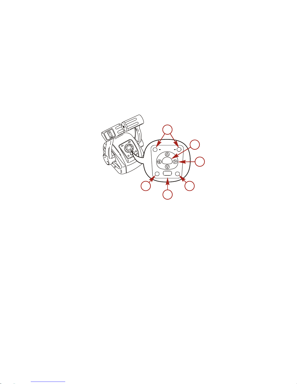
FEATURES AND CONTROLS
67
5. Neutral LEDs ‑ The neutral LEDs illuminate when engines are
in neutral gear position. The lights will flash when in throttle
only mode.
NOTE: Gear position is determined by sensing the position of the
shift actuator on the engine, not the position of the control handle.
6. Active LED ‑ The active LED illuminates to show the remote
control is active and ready for use.
7. Sync LED ‑ The "SYNC" LED illuminates when the RPM of the
engines are being synchronized by the DTS system.
ACTIVE
SYNC
THROTTLE
ONLY
STATION SELECT
a
b
c
d
e
f
NEUTRAL
SELECT
13854
a - Neutral LEDS
b - Select button
c - Arrow trackpad
d - Sync LED
e - Throttle only/station
select button
f - Active LED
SYNCHRONIZING ENGINES
The auto synchronizing feature, when engaged, will automatically
adjust all engine speeds to match the speed of the starboard
engine.
Page 76
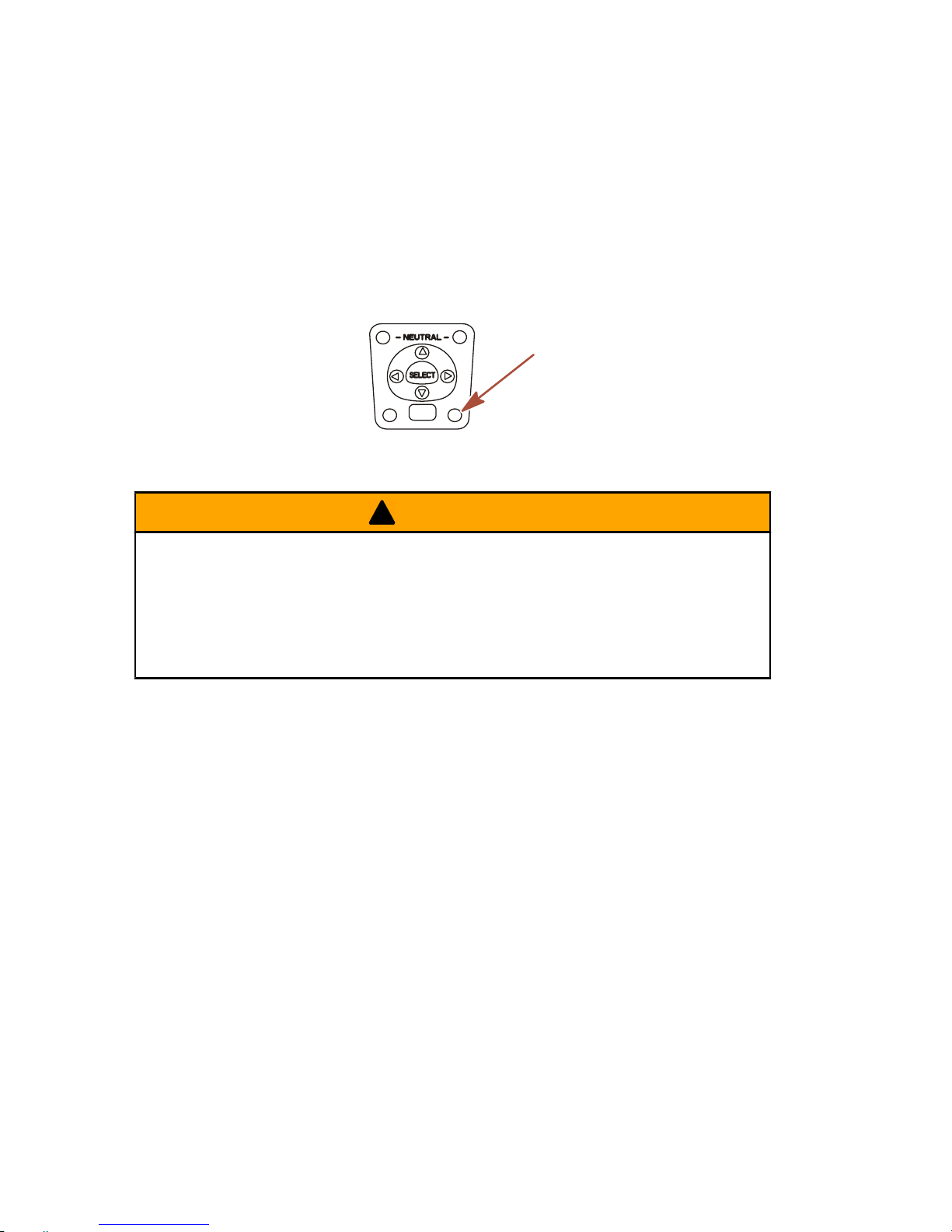
FEATURES AND CONTROLS
68
Engine auto synchronization will automatically engage when
engine speed is over 900 RPM for two seconds and remote control
handles are positioned within 10% of each other. The "SYNC" light
will turn on when the engines are synchronized. Auto
synchronization will stay engaged up to 95% throttle opening. To
disengage, move one or both control handles until they are more
than 10% apart, reduce engine speed below 900 RPM, or increase
engine speed beyond 95%.
22969
ACTIVE
SYNC
STATION SELECT
THROTTLE
ONLY
HELM TRANSFER
!
WARNING
Avoid serious injury or death from loss of boat control. The boat
operator should never leave the active station while engine is in
gear. Helm transfer should only be attempted while both stations
are manned. One‑person helm transfer should only be
performed while engine is in neutral.
NOTE: Idle position is preferred when doing a helm transfer. If
conditions do not allow the remote control to be placed at idle
position, a helm transfer can be done while in gear.
NOTE: The active light on the remote control will be illuminated at
the helm that is in control of the engine.
The helm transfer function allows the boat operator to select which
helm is in control of engine operation. Pressing the throttle only/
station select button two times allows engine control to be
transferred to a new helm. When a helm transfer is initiated, the
control will automatically start adjusting engine RPM and gear
position to match the control handle setting at the new helm. Adjust
the control handles to the desired throttle and gear position.
NOTE: There is a 10 second time frame to complete a helm
transfer. If the helm transfer is not completed, the action will be
cancelled and a double beep will sound. Pressing the throttle only/
station select button again will re‑initiate a helm transfer.
Page 77

FEATURES AND CONTROLS
69
1. Place active remote control lever to idle position.
2. Proceed to the inactive helm and position remote control lever
to the idle position.
3. Press throttle only/station select button two times. The
"ACTIVE" light will illuminate to indicate the remote control is
in control of the engine.
ACTIVE
STATION SELECT
ACTIVE
SYNC
STATION SELECT
THROTTLE
ONLY
THROTTLE
ONLY
22753
a
b
a
b
a - Active light b - Throttle only/station
select button
4. The "ACTIVE" light will switch off at the original helm.
Synchronizing Helms Prior To Helm Transfer
Pressing the throttle only/station select button one time allows the
boat operator 10 seconds to match up the control handle setting
at the new station with the handle setting that is at the old (to be
inactive) station. If the handle is not matched, the neutral light will
flash. The light blinks faster as the handle is nearing match
position. Once the light stays on continuously, the handle is
matched and the throttle only/station select button can be pressed
again to complete the transfer. This completes the transfer
process, and give control to the new station. If the helm transfer is
not completed within 10 seconds, the helm transfer is cancelled.
Shadow Mode Control with CAN Trackpad Features
and Operation
TRIPLE ENGINE THROTTLE AND SHIFT OPERATION
Movement of the handles on the remote control allows the boat
operator to control the engine throttle speed and gear shift
positions of all three engines.
The throttle and shift function is dependant on what engines are
running. Refer to the following table.
Page 78

FEATURES AND CONTROLS
70
Port Engine Center Engine Starboard Engine
Control Handle
Function
Running Running Running
Port engine throttle
and shift = controlled
by port control
handle
Starboard engine
throttle and shift =
controlled by
starboard control
handle
Center engine
throttle = average of
port and starboard
engines
Center engine shift =
neutral unless both
engines are in the
same gear
Running Running Off
Port and center
engine throttle and
shift = controlled by
port control handle
Off Running Running
Starboard and
center engine
throttle and shift =
controlled by
starboard control
handle
Running Off Running
Port engine throttle
and shift = controlled
by port control
handle
Starboard engine
throttle and shift =
controlled by
starboard control
handle
Running Off Off
Port engine throttle
and shift = controlled
by port control
handle
Page 79

FEATURES AND CONTROLS
71
Port Engine Center Engine Starboard Engine
Control Handle
Function
Off Off Running
Starboard engine
throttle and shift =
controlled by
starboard control
handle
Off (ignition key
switch turned on)
Running
Off (ignition key
switch turned on)
Center engine
throttle and shift =
neutral/idle unless
both control handles
are in the same gear
Turning off one of the outer engines while underway will cause the
center engine to go into forced neutral/idle. Operation to the center
engine can be restored by moving the control handle of the
functioning outer engine back into neutral position and then
re‑engaging. The center engine speed and gear shift will then be
controlled by the functioning outer engine.
Turning off the center engine while underway will have no effect
on the operation of the outer engines.
If a failure should occur while underway which causes one of the
outer engines into forced neutral/idle condition, the center engine
will also be forced to neutral/idle. Operation to the center engine
can be restored by moving the control handle of the functioning
outer engine back into neutral and then re‑engaging.
QUAD ENGINE THROTTLE AND SHIFT OPERATION
Movement of the handles on the remote control allows the boat
operator to control the engine throttle speed and gear shift
positions of all four engines.
The throttle and shift function is dependant on what engines are
running. Refer to the following table.
Page 80

FEATURES AND CONTROLS
72
Port Outer
Engine
Port Inner
Engine
Starboard
Inner Engine
Starboard
Outer Engine
Control Handle
Function
Running Running Running Running
Port inner and
outer engines
throttle and
shift =
controlled by
port control
handle
Starboard
inner and outer
engines throttle
and shift =
controlled by
starboard
control handle
Running Running Off Off
Port inner and
outer engine
throttle and
shift =
controlled by
port control
handle
Off Off Running Running
Starboard
inner and outer
engine throttle
and shift =
controlled by
starboard
control handle
Off (ignition
key switch
turned on)
Running Running Running
Port inner
engine throttle
and shift =
controlled by
port control
handle
Running Running Running
Off (ignition key
switch turned
on)
Starboard
inner engine
throttle and
shift =
controlled by
starboard
control handle
Page 81

FEATURES AND CONTROLS
73
Port Outer
Engine
Port Inner
Engine
Starboard
Inner Engine
Starboard
Outer Engine
Control Handle
Function
Off (ignition
key switch
turned off)
Running Running Running
Port inner
engine throttle
and shift =
controlled by
starboard
control handle
Running Running Running
Off (ignition key
switch turned
off)
Starboard
inner engine
throttle and
shift =
controlled by
port control
handle
Running Off Off Running
Port outer
engine throttle
and shift =
controlled by
port control
handle
Starboard
outer engine
throttle and
shift =
controlled by
starboard
control handle
Off (ignition
key switch
turned on)
Running Running
Off (ignition key
switch turned
on)
Port inner
engine throttle
and shift =
controlled by
port control
handle
Starboard
inner engine
throttle and
shift =
controlled by
starboard
control handle
Page 82

FEATURES AND CONTROLS
74
Turning off the starboard outer engine while underway will cause
the starboard inner engine to go into forced neutral/idle. Operation
to the inner engine can be restored by turning the starboard outer
engine ignition key to the on position and moving the starboard
control handle back into neutral position and then re‑engaging. The
inner engine speed and gear shift will then be controlled by the
starboard control handle.
Turning off the port outer engine while underway will cause the port
inner engine to go into forced neutral/idle. Operation to the inner
engine can be restored by turning the port outer engine ignition key
to the on position and moving the port control handle back into
neutral position and then re‑engaging. The inner engine speed and
gear shift will then be controlled by the port control handle.
Turning off one of the inner engines while underway will have no
effect on the operation of the outer engines.
If a failure should occur while underway which causes the
starboard outer engines into forced neutral/idle condition, the inner
starboard engine will also be forced to neutral/idle. Operation to
the inner engine can be restored by moving the starboard control
handle back into neutral and then re‑engaging.
If a failure should occur while underway which causes the port
outer engines into forced neutral/idle condition, the inner port
engine will also be forced to neutral/idle. Operation to the inner
engine can be restored by moving the port control handle back into
neutral and then re‑engaging.
Page 83

FEATURES AND CONTROLS
75
TRIM SWITCH AND KEY PAD FEATURES
1. Trim switch (if equipped) ‑ Operates the trim for all engines.
An accessory trim switch panel is required for trimming
engines individually.
22943
T
R
A
N
S
F
E
R
D
O
C
K
THROTTLE
ONLY
I
L
E
V
E
R
ALL
SYNC
TROLL
NEUTRAL
2. Neutral lights ‑ The neutral lights illuminate when the engine
is in neutral gear position. The lights will flash when the engine
is in throttle only mode.
NOTE: Gear position is determined by the position of the shift
actuator on the engine, not the position of the control handle.
3. Troll button ‑ Pressing the "TROLL" button activates troll
control. The troll control feature allows the boat operator to set
the engine speed for slow speed cruising or maneuvering. To
activate, move the control handles into forward detent and
press the button. Use the ‑ or + buttons to decrease or
increase speed, up to the maximum calibrated set point. If troll
control is set at a desired speed and then shut off, the system
remembers the set speed and will return to that speed when
re‑engaged. To turn off the troll control press the "TROLL"
button, move the throttle to a different speed, or shift the
engine into neutral.
4. Transfer button ‑ Pressing the "TRANSFER" button allows
engine operation to be transferred to a different helm. Refer
to Helm Transfer.
Page 84

FEATURES AND CONTROLS
76
5. Dock button ‑ Pressing the "DOCK" button initiates docking
mode. Docking mode reduces throttle capacity to
approximately 50% of normal throttle. To turn off docking
mode, shift the engine into neutral and press the "DOCK"
button.
6. Throttle only button ‑ Allows the boat operator to increase
engine RPM for warm‑up, without shifting the engine into gear.
To engage throttle only, move the control handle into the
neutral position. Press the throttle only button while moving
the control handle ahead to the forward detent. The horn will
sound once and the neutral light will start flashing. The horn
will sound twice when throttle only is engaged. Advance
throttle to increase engine RPM. To disengage, return control
handle to neutral position and press the throttle only button.
Engine RPM is limited to prevent engine damage.
7. 1 lever button ‑ Pressing the "1 LEVER" button initiates single
lever mode. Single lever mode enables the throttle and shift
functions of both engines to be controlled by the port control
handle. To turn off single lever mode, shift the engine into
neutral and press the "1 LEVER" button.
Page 85

FEATURES AND CONTROLS
77
8. Sync button ‑ Pressing the "SYNC" button turns off or on the
auto synchronization feature. Refer to Synchronizing
Engines
N
E
U
T
R
A
L
22945
SYNC
1 LEVER
NEUTRAL
TROLL
THROTTLE
ONLY
DOCK
TRANSFER
+
-
a
b
c
e
g
f
d
a - Neutral LEDS
b - Troll button
c - Transfer button
d - Dock button
e - Throttle only
f - 1 lever button
g - Sync button
9. Control handle tension adjustment screw ‑ This screw can be
adjusted to increase or decrease the tension on the control
handle (cover must be removed). This will help prevent
unwanted motion of the handle in rough water. Turn the screw
clockwise to increase tension and counterclockwise to
decrease tension. Adjust to tension desired.
Page 86

FEATURES AND CONTROLS
78
10.Detent tension adjustment screw ‑ This screw can be adjusted
to increase or decrease the effort to move control handle out
of detent positions (cover must be removed). Turning the
screw clockwise will increase tension. Adjust to tension
desired.
a
b
28556
a - Detent tension
adjustment screw
b - Control handle tension
adjustment screw
SYNCHRONIZING ENGINES
The auto synchronizing feature, when engaged, will automatically
adjust all engine speeds to match the speed of the starboard
engine.
Press the "SYNC" button on the CAN trackpad to turn auto
synchronization on or off. When the sync LED is yellow, the
"SYNC" button has been pressed, but the conditions are not right
for auto synchronization to engage. When the sync LED turns red,
engine synchronization has been engaged. The engines will
remain synchronized as long as engine speed is over 900 RPM for
two seconds, remote control handles are positioned within 10% of
each other, and the engines are below 95% throttle opening.
Page 87

FEATURES AND CONTROLS
79
To disengage the auto synchronization feature, press the "SYNC"
button.
SYNC
1 LEVER
NEUTRAL
TROLL
THROTTLE
ONLY
DOCK
TRANSFER
+
-
22590
HELM TRANSFER
!
WARNING
Avoid serious injury or death from loss of boat control. The boat
operator should never leave the active station while engine is in
gear. Helm transfer should only be attempted while both stations
are manned. One‑person helm transfer should only be
performed while engine is in neutral.
NOTE: Neutral position is preferred when doing a station transfer.
If conditions do not allow the remote control to be placed in the
neutral position, a helm transfer can be done while in gear.
The helm transfer function allows the boat operator to select which
helm is in control of engine operation. Pressing the "TRANSFER"
button two times allows engine control to be transferred to a new
helm. When a helm transfer is initiated, the control will
automatically start adjusting engine RPM and gear position to
match the control handle setting at the new helm. Adjust the control
handles to the desired throttle and gear position.
Once the "TRANSFER" button is pressed, the transfer LED will
light up and one beep will sound. Press the "TRANSFER" button
again to complete the helm transformation. When helm
transformation is complete, another beep will sound and the
transfer LED will turn off.
Page 88

FEATURES AND CONTROLS
80
NOTE: There is a 10 second time frame to complete a helm
transfer. If the helm transfer is not completed, the action will be
cancelled and a double beep will sound. Pressing the
"TRANSFER" button again will re‑initiate a helm transfer.
SYNC
1 LEVER
NEUTRAL
TROLL
THROTTLE
ONLY
DOCK
TRANSFER
+
-
22593
Synchronizing Helms Prior To Transfer
Pressing the "TRANSFER" button allows the boat operator 10
seconds to match up the control handle settings at the new helm
with the handle settings that are at the old (to be inactive) helm. If
the handles are not matched, the neutral lights will flash. The light
blinks faster as the handles are nearing match position. Once the
light stays on continuously, the handles are matched and the
button can be pressed again to complete the transfer. This
completes the transfer process, and gives control to the new
station. If the helm transfer is not completed within 10 seconds, the
action will be cancelled.
Warning System
WARNING HORN SIGNALS
When the key switch is turned to the "ON" position, the horn
(located on the command module harness) will turn on for a
moment as a test to indicate the horn is working.
There are two types of warning horns to alert the operator of an
active problem within the engine’s operating system.
1. Continuous six second beep: Indicates a critical engine
condition. Depending on the condition, the Engine Guardian
System may engage and protect the engine by limiting it’s
power. You should return to port immediately and contact your
servicing dealer.
Page 89

FEATURES AND CONTROLS
81
2. Intermittent short beeps for six seconds: Indicates a
non‑critical engine condition. This condition does not require
immediate attention. You may continue using your boat,
however, depending on the nature of the problem, the
engine’s power may be limited by the Engine Guardian
System (see Engine Guardian System following) to protect the
engine. You should contact your servicing dealer at your
earliest convenience.
It is important to note that in either of the above scenarios, the horn
will only sound one time. If you key the engine off and re‑start it,
the horn will sound again, one time, if the fault is still present. For
visual display of the specific engine functions and additional engine
data, refer to SmartCraft Product information, following.
A few of the non‑critical conditions indicated by the intermittent
short beeps for six seconds can be corrected by the operator.
These operator correctable conditions are as follows:
• Water in the engine mounted fuel filter. Refer to Maintenance
– Water Separating Fuel Filter
• Cooling system (water pressure or engine temperature)
problem. Stop the engine and check the water intake holes in
the lower unit for obstruction
• Low engine oil level. Refer to Fuel and Oil – Checking and
Adding Engine Oil.
ENGINE GUARDIAN SYSTEM
The Engine Guardian System monitors the critical sensors on the
engine for any early indications of problems. Engine Guardian is
functional whenever your engine is operating, so you never have
to be concerned about whether or not you are protected. The
system will respond to a problem by sounding the warning horn for
six seconds and/or reducing engine power in order to provide
engine protection.
If the Guardian System has been activated, reduce throttle speed.
The problem will need to be identified and corrected, if possible.
The system must be reset before the engine will operate at higher
speeds. Moving the throttle lever back to the idle position will reset
the system.
Page 90

FEATURES AND CONTROLS
82
SMARTCRAFT PRODUCT
A Mercury SmartCraft System instrument package can be
purchased for this outboard. A few of the functions the instrument
package will display are engine RPM, coolant temperature, oil
pressure, water pressure, battery voltage, fuel consumption and
engine operating hours.
The SmartCraft Instrument package will also aid in Engine
Guardian diagnostics. The SmartCraft Instrument package will
display critical engine alarm data and potential problems.
Power Trim and Tilt
The outboard has a trim/tilt control called power trim. This enables
the operator to easily adjust the position of the outboard by
pressing the trim switch. Moving the outboard in closer to the boat
transom is called trimming in or down. Moving the outboard further
away from the boat transom is called trimming out or up. The term
trim generally refers to the adjustment of the outboard within the
first 20° range of travel. This is the range used while operating the
boat on plane. The term tilt is generally used when referring to
adjusting the outboard further up out of the water. With the engine
turned off and ignition switch turned on, the outboard can be tilted
out of the water. At low idle speed, the outboard can also be tilted
up past the trim range to permit, for example, shallow water
operation.
14834
b
c
a
a - Trim switch
b - Trim range
c - Tilt range
Page 91

FEATURES AND CONTROLS
83
POWER TRIM OPERATION
With most boats, operating around the middle of the trim range will
give satisfactory results. However, to take full advantage of the
trimming capability there may be times when you choose to trim
your outboard all the way in or out. Along with an improvement in
some performance aspects comes a greater responsibility for the
operator, and this is being aware of some potential control hazards.
The most significant control hazard is a pull or torque that can be
felt on the steering wheel or tiller handle. This steering torque
results from the outboard being trimmed so that the propeller shaft
is not parallel to the water surface.
!
WARNING
Trimming the outboard beyond a neutral steering condition may
result in a pull on the steering wheel or tiller handle and loss of
boat control. Maintain control of the boat if trimming beyond a
neutral steering condition.
Consider the following lists carefully.
1. Trimming In or Down Can:
• Lower the bow.
• Result in quicker planing off, especially with a heavy load
or a stern heavy boat.
• Generally improve the ride in choppy water.
• Increase steering torque or pull to the right (with the normal
right hand rotation propeller).
• In excess, can lower the bow of some boats to a point
where they begin to plow with their bow in the water while
on plane. This can result in an unexpected turn in either
direction (called bow steering or over‑steering) if any turn
is attempted, or if a significant wave is encountered.
Page 92

FEATURES AND CONTROLS
84
!
WARNING
Operating the boat at high speeds with the outboard trimmed
too far under can create excessive bow steer, resulting in the
operator losing control of the boat. Install the trim limit pin in a
position that prevents excessive trim under and operate the
boat in a safe manner.
• In rare circumstances, the owner may decide to limit the
trim in. This can be accomplished by purchasing a stainless
steel tilt pin from your dealer and inserting it in whatever
adjustment hole in the transom brackets is desired. The
non‑stainless steel shipping bolt should not be used in this
application other than on a temporary basis.
2. Trimming Out or Up can:
• Lift the bow higher out of the water.
• Generally increase top speed.
• Increase clearance over submerged objects or a shallow
bottom.
• Increase steering torque or pull to the left at a normal
installation height (with the normal right hand rotation
propeller).
• In excess can cause boat porpoising (bouncing) or
propeller ventilation.
• Cause engine overheating if any cooling water intake holes
are above the water line.
TRIM WITHOUT KEY
Trim without key is a method of allowing trim operation after the
ignition key switch is turned off. The command module and PCM
remain powered and are able to process trim requests for up to 15
minutes after the key switch is turned off. The command module
does not process any requests other than trim during this period.
Once the 15 minute period expires, the command module sends
a command through the CAN lines to shut down the PCM. On
multi‑engine applications, the timeout is managed seperately for
each engine.
Page 93

FEATURES AND CONTROLS
85
The trim without key period may be ended at any time by moving
the control handle to Wide Open Throttle Reverse (WOTR) with
the key off. To end the 15 minute period for the center engine in a
shadow mode application, ensure all ignition key switches are in
the "OFF" position and both remote control handles are in the Wide
Open Throttle Reverse (WOTR) position.
TILTING TO FULL UP POSITION
Tilt At Helm
NOTE: The trim/tilt switch will remain active for 15 minutes after
the ignition key switch has been turned off.
1. If the ignition key switch has been turned off for over 15
minutes, turn it to the "ON" position.
2. Press the trim/tilt switch to the up position. The outboard will
tilt up until the switch is released or it reaches its maximum tilt
position.
Tilt At Engine
The cowl mounted auxiliary tilt switch can be used to tilt the
outboard with the key switch in the "OFF" position.
Tilt Support Lever
1. Engage the tilt support lever, by rotating knob to bring the
support lever upward.
2. Lower outboard to rest on the tilt support lever.
3. Disengage the tilt support lever, by raising the outboard off the
support lever and rotating the tilt support lever down. Lower
the outboard.
b
a
27778
a - Tilt support lever b - Knob
Page 94

FEATURES AND CONTROLS
86
MANUAL TILTING
If the outboard cannot be tilted using the power trim/tilt switch, the
outboard can be manually tilted.
NOTE: The manual tilt release valve must be tightened before
operating the outboard to prevent the outboard from tilting up
during reverse operation.
1. Turn out the manual tilt release valve 3 turns
counterclockwise. This allows manual tilting of the outboard.
Tilt the outboard to the desired position and tighten the manual
tilt release valve.
22362
AUXILIARY TILT SWITCH
NOTE: This model allows the auxiliary tilt switch to be mounted on
either the port side (shown) or on the starboard side.
This switch can be used to tilt the outboard up or down using the
power trim system.
14831
a
a - Auxiliary tilt switch (port side)
SHALLOW WATER OPERATION
When operating your boat in shallow water, you can tilt the
outboard beyond the maximum trim range to prevent hitting
bottom.
1. Reduce engine speed below 2000 RPM.
Page 95

FEATURES AND CONTROLS
87
2. Tilt outboard up. Make sure all the water intake holes stay
submerged at all times.
3. Operate the engine at slow speed only. If engine speed
exceeds 2000 RPM, the outboard will automatically return
down to the maximum trim range.
Page 96

OPERATION
88
Pre‑Starting Check List
• Operator knows safe navigation, boating, and operating
procedures.
• An approved personal flotation device of suitable size for each
person aboard and readily accessible (it is the law).
• A ring type life buoy or buoyant cushion designed to be thrown
to a person in the water.
• Know your boats maximum load capacity. Look at the boat
capacity plate.
• Fuel supply OK.
• Arrange passengers and load in the boat so the weight is
distributed evenly and everyone is seated in a proper seat.
• Tell someone where you are going and when you expect to
return.
• It is illegal to operate a boat while under the influence of
alcohol or drugs.
• Know the waters and area you will be boating; tides, currents,
sand bars, rocks, and other hazards.
• Make inspection checks listed in Maintenance ‑ Inspection
and Maintenance Schedule.
Operating In Freezing Temperatures
When using your outboard or having your outboard moored in
freezing or near freezing temperatures, keep the outboard tilted
down at all times so the gearcase is submerged. This prevents
trapped water in gearcase from freezing and causing possible
damage to the water pump and other components.
If there is a chance of ice forming on the water, the outboard should
be removed and drained completely of water. If ice should form at
the water level inside the outboard driveshaft housing, it will block
water flow to the engine causing possible damage.
Operating In Salt Water Or Polluted Water
We recommend that you flush the internal water passages of your
outboard with fresh water after each use in salt or polluted water.
This will prevent a buildup of deposits from clogging the water
passages. Refer to Maintenance ‑ Flushing The Cooling System.
Page 97

OPERATION
89
If you keep your boat moored in the water, always tilt the outboard
so the gearcase is completely out of water (except in freezing
temperatures) when not in use.
Wash the outboard exterior and flush out the exhaust outlet of the
propeller and gearcase with fresh water after each use. Each
month, spray Mercury Precision or Quicksilver Corrosion Guard on
external metal surfaces. Do not spray on corrosion control anodes
as this will reduce the effectiveness of the anodes.
Setting Trim Angle While Running Engine at Idle
Speed
The exhaust relief hole on the outboard can become submerged
on some boats if the engine is trimmed full in while running at idle
speed. This may result in exhaust restriction, rough idle, excessive
smoke, and fouled spark plugs. If this condition exists, trim
outboard up until exhaust relief hole is out of the water.
or35-1
a
b
a - Relief hole submerged (wrong)
b - Relief hole above water line (correct)
Engine Break‑in Procedure
IMPORTANT: Failure to follow the engine break‑in procedures can
result in poor performance throughout the life of the engine and
can cause engine damage. Always follow break‑in procedures.
1. For the first two hours of operation, run the engine at varied
throttle settings up to 4500 RPM or at three‑quarter throttle,
and at full throttle for approximately one minute every ten
minutes.
2. For the next eight hours of operation, avoid continuous
operation at full throttle for more than five minutes at a time.
Page 98

OPERATION
90
Starting The Engine
Before starting, read the Pre‑Starting Check List, Special
Operating Instructions, Engine Break‑in Procedure and Gear
Shifting in the Operation Section and the remote control features
and operation in the Features and Controls Section.
NOTICE
Failure to provide sufficient cooling water will damage the water
pump and cause the engine to overheat. Provide a sufficient
supply of water at the water inlets during operation.
1. Make sure the cooling water intake is submerged.
14836
2. Check the engine oil level.
27780
3. Open fuel tank vent on manual venting type tanks.
19748
NOTE: The engine will not start unless the lanyard is set to the
"RUN" position.
Page 99

OPERATION
91
4. Set the lanyard stop switch to the "RUN" position. Refer to
General Information ‑ Lanyard Stop Switch.
19791
5. Shift outboard to neutral (N) position.
F
N
R
3413
F
N
R
3417
NOTE: For initial start of a new engine or for an engine that ran
out of fuel or was drained of fuel, the fuel system should be filled
as follows:
Turn the ignition key switch to the "ON" position for approximately
one minute. This operates the fuel lift pump. Turn the ignition key
switch back to the "OFF" position and then return the ignition key
switch to the "ON" position again for an additional minute. Turn
the ignition key switch back to the "OFF" position. The filling of the
fuel system is complete.
Page 100

OPERATION
92
6. Ignition key starting ‑ Turn the ignition key to "START" position
and release the key. The electronic starting system will
automatically crank the engine for starting. If the engine fails
to start, the engine will stop cranking. Turn the key to "START"
position again until engine starts.
S
T
A
R
T
O
F
F
A
C
C
O
N
S
T
A
R
T
O
F
F
A
C
C
O
N
3485
7. After engine starts, check for a steady stream of water flowing
out of the water pump indicator hole.
15301
IMPORTANT: If no water is coming out of the water pump
indicator hole, stop engine and check the cooling water intake for
obstruction. No obstruction may indicate a water pump failure or
blockage in the cooling system. These conditions will cause the
engine to overheat. Have the outboard checked by your dealer.
Operating the engine while overheated will cause engine damage.
Gear Shifting
DTS PANEL MOUNT REMOTE CONTROL
IMPORTANT: Never shift outboard into gear unless engine speed
is at idle. Do not shift outboard into forward or reverse when the
engine is not running.
 Loading...