

Page 1

Table of contents
BEFORE DRIVING
Introduction 2
Instrumentation 9
Controls and features 13
Seating and safety restraints 59
STARTING AND DRIVING
Starting your vehicle 89
Driving 96
Roadside emergencies 118
SERVICING
Maintenance and care 136
Capacities and specifications 185
Reporting safety defects 192
Index 193
Filling station information 200
1
Page 2

Introduction
The following icons appear in this
Owner’s Guide:
indicates a warning. Read the
following section on Warnings for
a full explanation of warnings.
indicates that vehicle
information related to recycling
and other environmental concerns
will follow.
Warnings
Warnings remind you to be
especially careful in those areas
where carelessness can cause
damage to your vehicle or personal
injury to yourself, your passengers
or other people. Please read all
Warnings carefully.
Notice to owners of utility-type
vehicles
As with other vehicles of this type,
failure to operate this vehicle
correctly may result in loss of
control or an accident. Be sure to
read Special driving instructions
for AWD vehicles later in this
Owner’s Guide and the special
supplement included with AWD
and 4x4 vehicles entitled
Four-Wheeling.
Four-Wheeling presents safe
driving practices to owners of AWD
and 4x4 utility vehicles. Your AWD
vehicle handles differently than an
ordinary passenger car and has
some special safety considerations.
This is because your AWD vehicle
has several design and equipment
2
Page 3

differences for towing, hauling, and
off-road operation. For this reason,
Mercury urges you to read and
understand the contents of the
Four-Wheeling supplement.
Breaking in your vehicle
Your new vehicle goes through an
adjustment or breaking-in period
during the first 1,000 miles (1,600
km) of driving. During this period:
• Change your vehicle’s speed
often as you drive. Do not drive
at one speed for a long time.
• Use only the type of engine oil
Ford recommends. Do not use
special “break-in” oils.
• Avoid sudden stops. The
break-in period for brake linings
lasts for 1,600 km (1,000 miles)
of highway driving or 160 km
(100 miles) of city driving.
Information about this guide
This guide describes equipment
and gives specifications for
equipment that was in effect when
this guide was approved for
printing. Mercury may discontinue
models or change specifications or
design without any notice and
without incurring obligation.
Introduction
3
Page 4
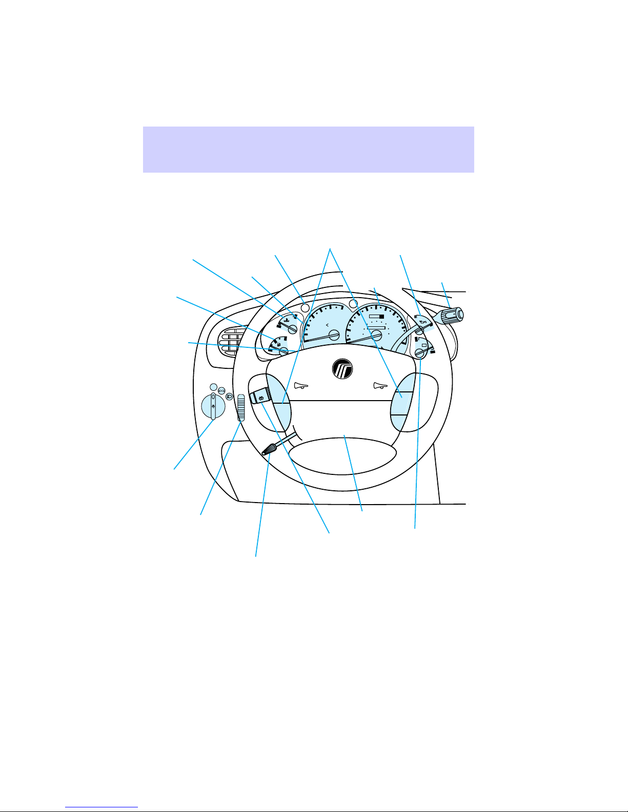
Instrumentation
Engine coolant
temperature
gauge (pg. 7 )
Fuel gauge
(pg. 7)
Hazard
flasher
control
(not
shown)
(pg. 27)
Headlamp
control
(pg. 13)
Warning lights
Tachometer
(pg. 6)
OFF
(pg. 8)
E
Speed
control
(pg. 23)
Engine oil
pressure
gauge
(pg. 7)
Gearshift
(includes
overdrive
button)
Speedometer
(pg. 26)
(pg. 6)
H
C
F
ON
OFF
UNLEADED
FUEL ONLY
2
1
0
RPMx 1000
P RND21
SRS
5
6
4
3
60
70
50
oooo
40
80
100
80
120
140
60
30
40
000000
20
20
10
0
H
90
160
100
180
110
120
km/hMPH
H
RSM
SET
ACCEL
COAST
O/D
ON/OFF
L
- +
L
L
Instrument
panel dimmer
switch (pg. 14)
4
Tilt steering
wheel lever
(pg. 27)
Driver air bag
(pg. 78)
Turn signal and
wiper/washer
control (pg. 24)
Charging
system gauge
(pg. 7)
Page 5
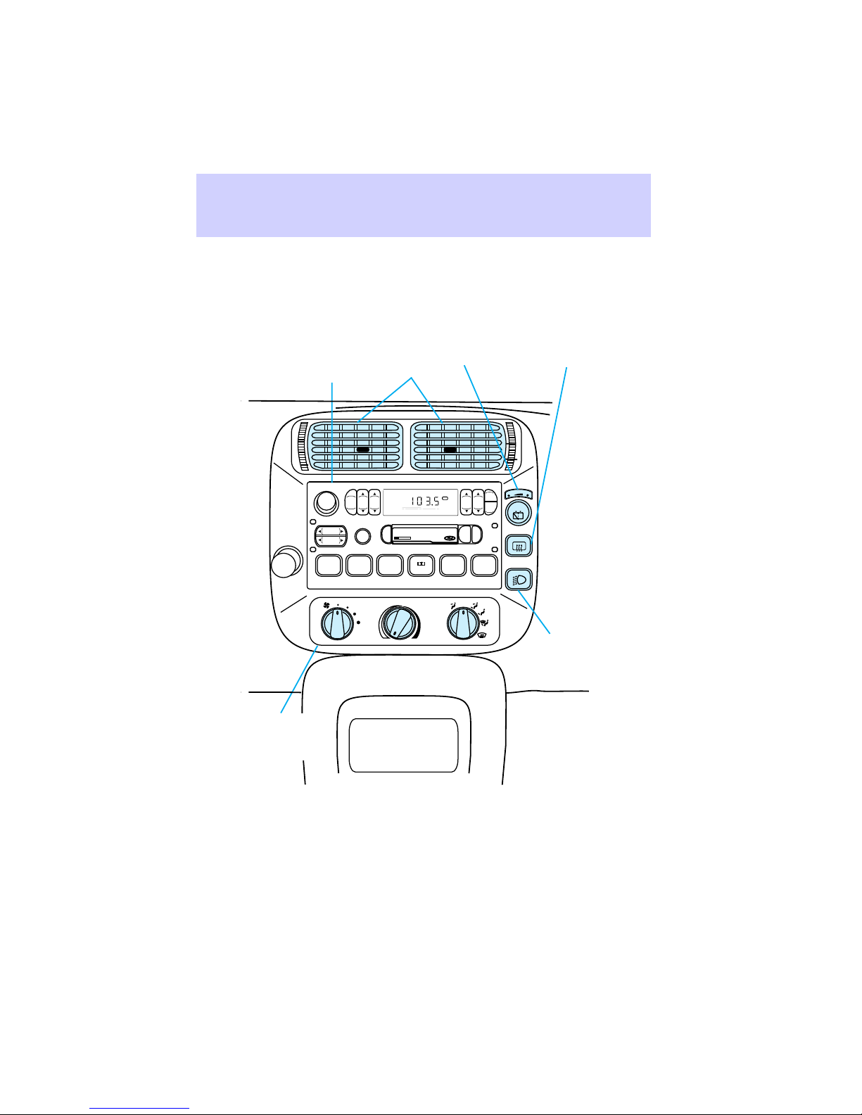
Instrumentation
Electronic sound
system; refer to Audio
Guide (premium stereo
cassette with CD DJ
shown) (pg. 16)
VOL – PUSH ON
AM
FM
SEEK
TUNE
DISCS
REW
1
Climate
controls
(pg. 17)
BASSTREB
SCAN
FF
2
Vents
(pg. 17)
FM 1
EJ
DOLBY SYSTEM
SIDE 1-2
4
3
Rear
wiper/washer
control (pg. 15)
OFF
BAL FADE
TAPE CD
COMP5SHUFFLE
OFF
CLK
AUTO
PUSH
SET
6
ST
A/C
*
MAX
*
A/C
Rear window
defroster
control (pg. 15)
R. WIPE
HI
Fog lamp
control (pg. 16)
5
Page 6
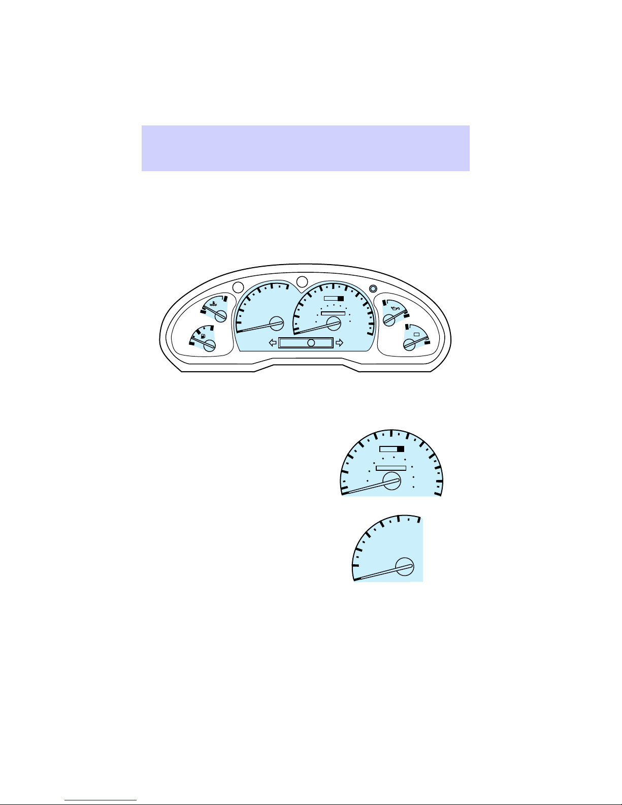
Instrumentation
INSTRUMENT CLUSTER
Instrument cluster gauges
E
Speedometer
Tachometer
5
6
4
3
H
C
F
UNLEADED
FUEL ONLY
2
1
0
RPMx 1000
P RND21
50
oooo
40
80
60
30
40
000000
20
20
10
0
MPH km/h
60
70
80
100
120
140
160
180
30
20
10
0
90
100
110
120
40
20
50
80
60
40
000000
3
2
H
60
oooo
100
5
4
UNLEADED
FUEL ONLY
L
H
- +
L
70
80
120
90
140
100
160
110
180
120
km/hMPH
6
1
0
RPMx1000
6
Page 7
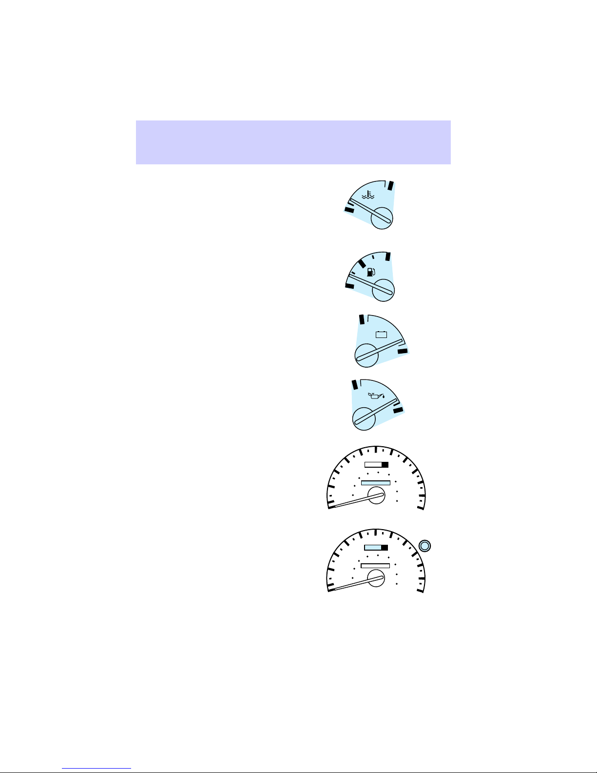
Engine coolant
Fuel gauge
Voltage gauge
Oil pressure
Instrumentation
H
C
F
E
H
- +
L
H
L
Odometer
Trip odometer and reset
button
60
70
50
40
60
30
40
20
20
10
0
50
40
60
30
40
20
20
10
0
oooo
100
80
120
000000
60
70
oooo
100
80
120
000000
80
90
140
100
160
110
180
120
km/hMPH
80
90
140
100
160
110
180
120
km/hMPH
7
Page 8
Instrumentation
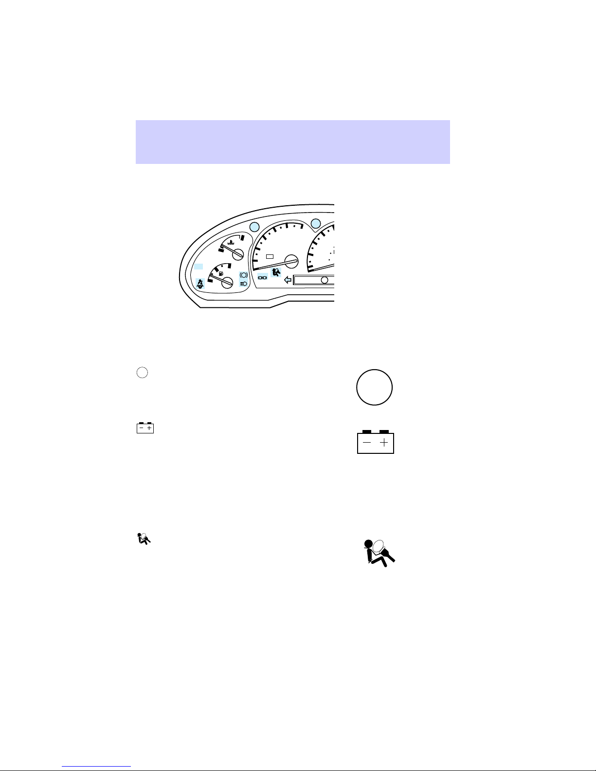
Instrument cluster warning and
indicator lights
CHECK
GAGE
3
H
C
DOOR
AJAR
DOOR
illuminates when the ignition
AJAR
key is turned to the ON or START
F
E
position and a door or liftgate is
opened.
CHECK
GAGE
illuminates when the ignition is
turned to ON and the engine
temperature is high, the oil
pressure is low, or the fuel level is
near empty.
illuminates when there is a
problem with the generator or
charging system.
2
- +
1
0
BRAKE
ABS
! P
4
5
UNLEADED
FUEL ONLY
RPMx 1000
FUEL
RESET
6
P RND21
50
40
60
30
40
20
20
10
0
MPH km/h
60
70
oooo
100
80
120
000000
80
140
90
160
100
180
110
200
DOOR
AJAR
CHECK
GAGE
H
L
4X4
4WD
LOW
H
- +
L
FUEL
illuminates when the ignition
RESET
key is turned to ON and the fuel
pump shutoff switch has been
triggered. Refer to Fuel pump
shutoff switch in Roadside
emergencies for more information.
illuminates when the air bag
system requires servicing.
8
FUEL
RESET
Page 9
Instrumentation
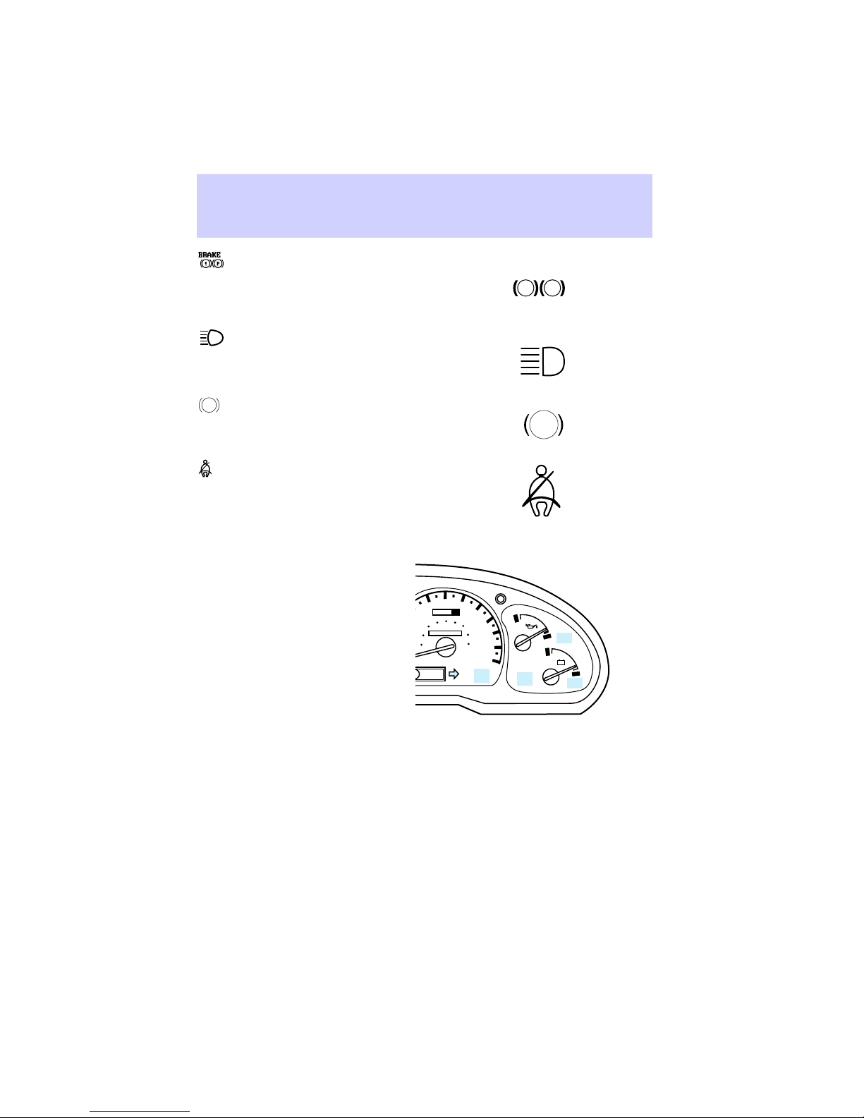
illuminates when the parking
brake is activated, brake fluid level
is low, or break system requires
service.
illuminates when the
headlamp high beams are on.
ABS
illuminates when the anti-lock
brake system requires service.
illuminates when the ignition
key is turned to ON and the safety
belt is not buckled. The light will
remain illuminated for one to two
minutes or until the safety belt is
buckled.
5
6
4
3
H
C
DOOR
AJAR
F
ABS
BRAKE
UNLEADED
FUEL ONLY
2
- +
1
0
RPMx 1000
! P
E
20
10
0
P RND21
60
50
oooo
40
100
80
60
30
40
000000
20
MPH km/h
BRAKE
! P
ABS
70
80
120
140
160
180
90
100
120
ANTI-
THEFT
110
H
CHECK
ENGINE
SPEED
L
CONT
H
- +
L
O/D
OFF
SPEED
illuminates when the engine
CONT
is running and speed control is
turned on.
SPEED
CONT
9
Page 10

Instrumentation
O/D
the transmission control
OFF
indicator light (TCIL) illuminates
when the transmission control
switch on the end of the gearshift
lever is pushed and the
D
(Overdrive) mode is turned
off.
O/D
indicates the status of the
OFF
transmission and may flash steadily
if a malfunction is detected. If
flashing persists, have your
transmission serviced by your
dealer as soon as possible.
If this condition persists, your
transmission may be damaged.
CHECK
illuminates when the
ENGINE
emission control system requires
service.
O/D
OFF
CHECK
ENGINE
THEFT
(if equipped) illuminates
when the anti-theft system is
arming and flashes when the
anti-theft system is armed. Refer
to Interior features for additional
information regarding the
anti-theft system.
illuminates when the lefthand or right-hand turn signal or
the hazard lamps are illuminated.
10
THEFT
Page 11
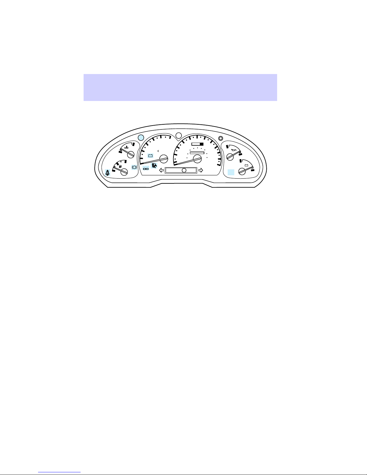
How to test the instrument
cluster lights
CHECK
GAGE
H
C
F
ABS
E
1
BRAKE
5
6
4
3
UNLEADED
FUEL ONLY
2
- +
0
RPMx 1000
! P
P RND21
Turn the ignition key to ON
without starting the engine. The
warning and indicator lights shown
above will illuminate for a brief
time. If any of these lights do not
illuminate, have your vehicle
serviced.
Warning chimes
Safety belt warning chime
Refer to the Seating and safety
restraints chapter for information
on the safety belt warning chime.
Supplemental restraint system
(SRS) warning chime
Refer to the Seating and safety
restraints chapter for information
on the SRS warning chime.
Key–in–ignition warning chime
A warning chime sounds when the
key is left in the ignition in the
OFF, LOCK, or ACCESSORY
position and the driver’s door is
opened.
50
oooo
40
80
60
30
40
000000
20
20
10
0
MPH km/h
Instrumentation
60
70
80
100
120
140
160
180
90
100
110
120
H
CHECK
ENGINE
L
H
- +
L
11
Page 12

Instrumentation
Headlamps on warning chime
A warning chime sounds when the
headlamps are on (and key is not
in the ignition), the ignition is off,
and a door is opened.
12
Page 13
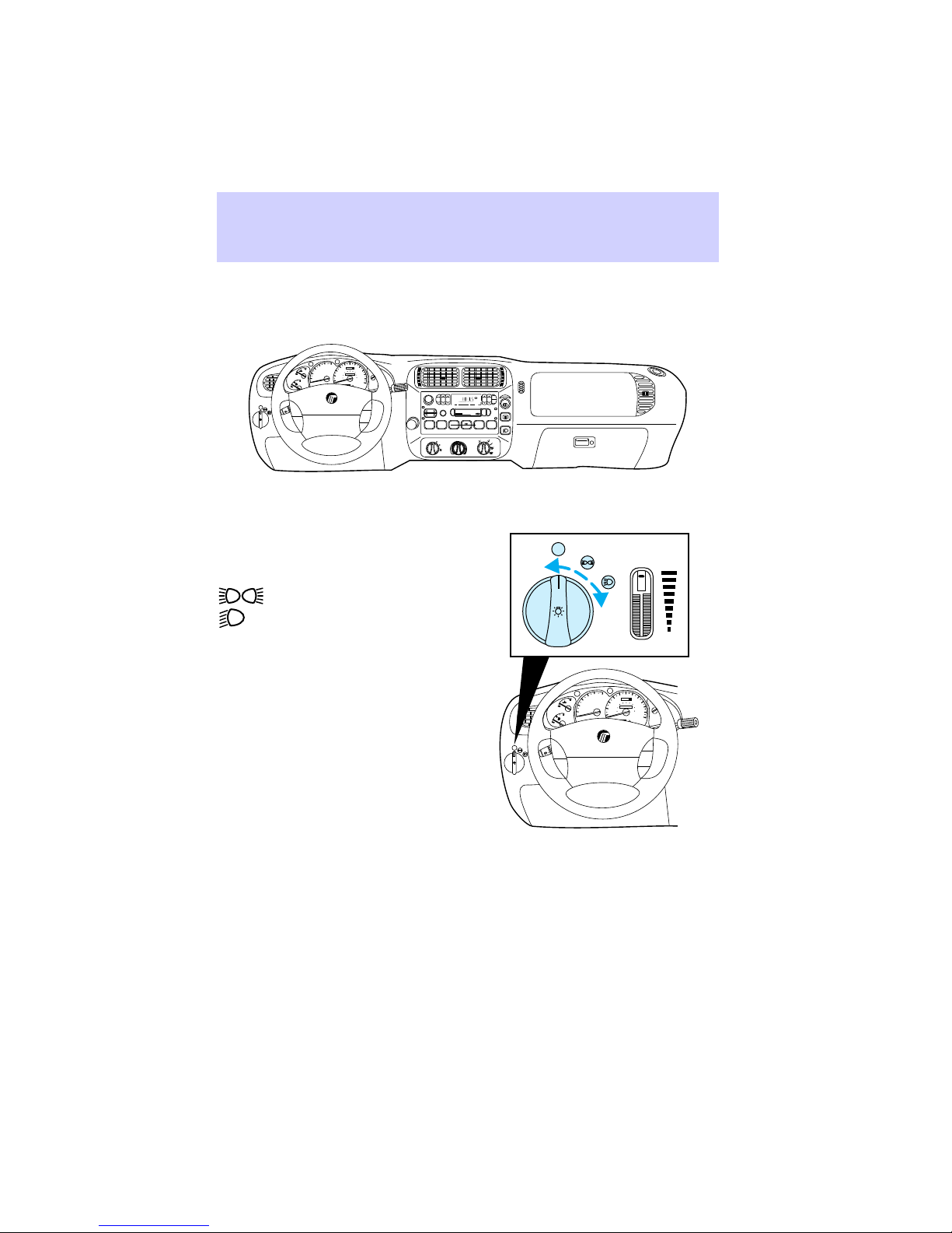
INSTRUMENT PANEL
CONTROLS
60
5
6
70
50
4
oooo
40
80
100
80
120
3
H
C
F
E
OFF
ON
OFF
140
60
UNLEADED
30
90
FUEL ONLY
40
160
2
000000
100
20
180
20
1
110
10
0
0
120
km/h
RPMx1000
P RND21
SRS
RSM
SET
ACC
COAST
VOL – PUSH ON
SEEK
REW
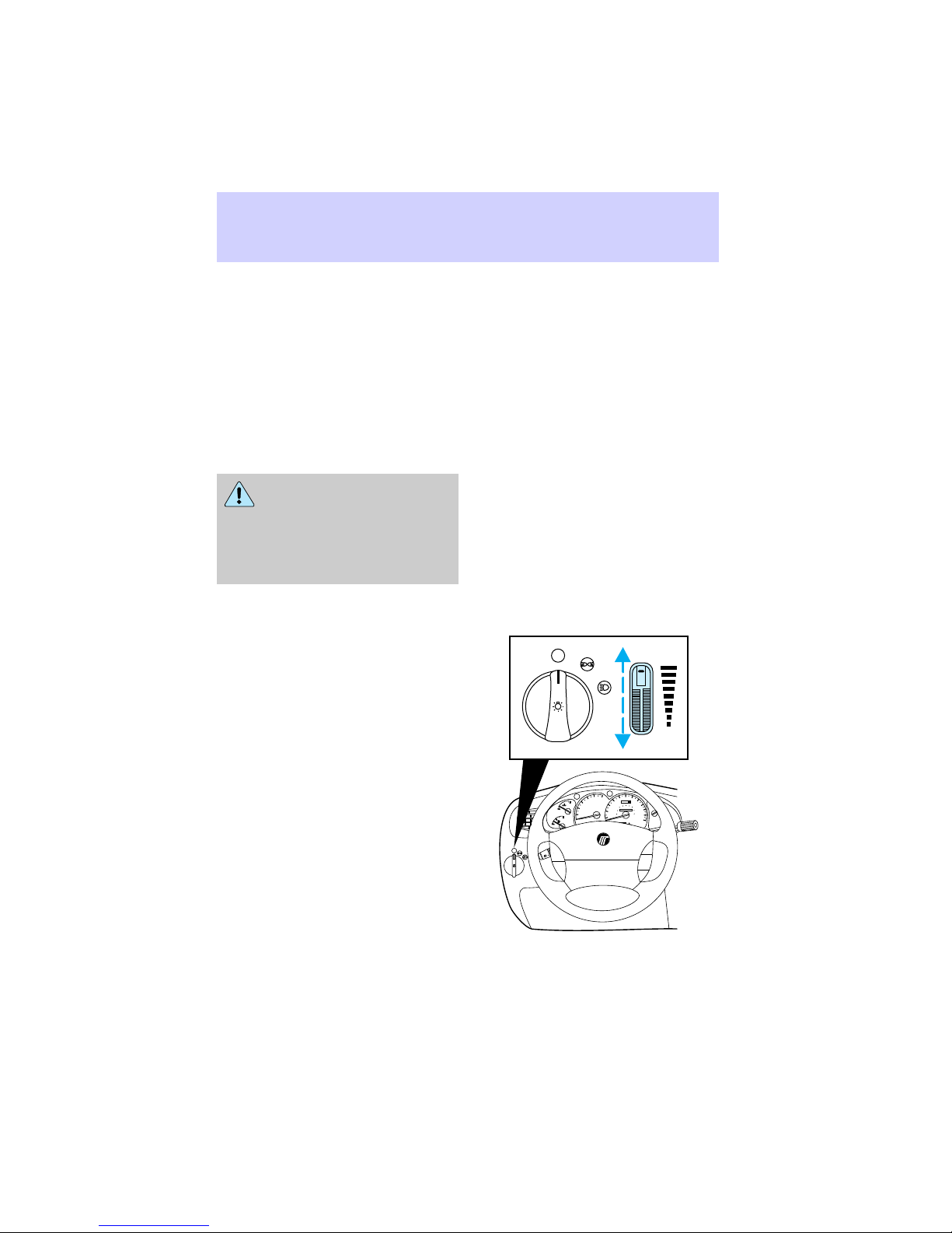
Headlamp switch
This switch operates the parking
lamps and headlamps.
OFF Exterior lamps off
Parking lamps ON
Headlamps ON
Controls and features
CLK
ST
FM 1
AM
BALFADE
BASSTREB
FM
SCAN
TUNE
DISCS
FF
2
1
LO
HI
AUTO
PUSH
SET
TAPE CD
EJ
DOLBY SYSTEM
COMP5SHUFFLE
SIDE 1-2
6
4
3
OFF
A/C
*
MAX
*
A/C
OFF
DIM
60
5
6
70
50
4
oooo
40
80
100
80
120
3
H
2
C
1
0
F
E
OFF
ON
OFF
UNLEADED
FUEL ONLY
RPMx1000
P RND21
SRS
140
60
30
90
40
160
000000
100
20
180
20
110
10
0
120
km/h
RSM
SET
ACC
COAST
Autolamp delay system (if
equipped)
The autolamp sets the headlamps
to turn on and off automatically.
Refer to Overhead controls for
instructions on using the autolamp.
13
Page 14
Controls and features
Daytime running light (DRL)
system (if equipped)
The daytime running light (DRL)
system turns the high beam lamps
on, with a reduced light output,
when:
• The headlamp knob is in the
OFF position.
• The engine is running.
• The parking brake is released.
The daytime running light
(DRL) system will not
illuminate the tail lamps and
parking lamps. Turn on your
headlamps at dusk. Failure to do
so may result in a collision.
Panel dimmer dial
Instrument panel illumination,
interior lamps and cargo lamp
brightness can be adjusted with
this dial.
Move thumbwheel up to brighten
lamps. Move thumbwheel down to
dim lamps.
OFF
DIM
14
H
2
C
1
0
F
E
OFF
ON
OFF
UNLEADED
FUEL ONLY
RPMx1000
P RND21
SRS
140
60
30
90
40
160
000000
100
20
180
20
110
10
0
120
km/h
RSM
SET
ACC
COAST
60
5
6
70
50
4
oooo
40
80
100
80
120
3
Page 15
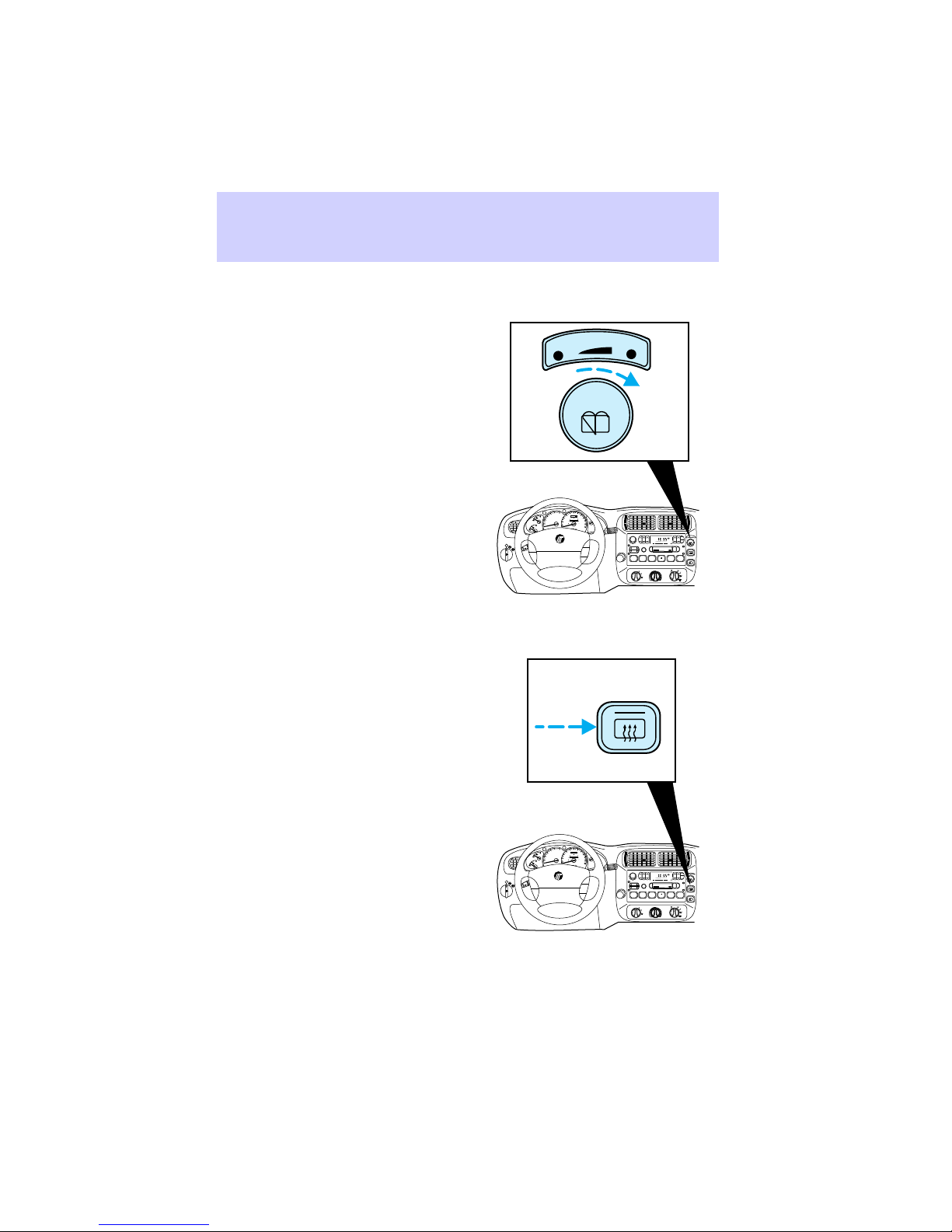
Liftgate wiper and washer
Turn the knob to adjust wiper
speed. Push the knob in to activate
the washer.
Rear window defroster
Push the button to activate the
defroster. The indicator light will
turn on and the defroster will turn
off automatically in ten minutes.
Push the button again to turn off.
Controls and features
R. WIPE
OFF
60
5
6
70
50
4
oooo
40
80
100
80
120
3
H
140
60
UNLEADED
30
90
FUEL ONLY
40
160
2
C
000000
100
20
180
20
1
110
10
0
0
120
km/h
F
RPMx1000
E
OFF
P RND21
ON
OFF
COAST
SRS
PUSH
RSM
SET
ACC
HI
VOL – PUSH ON
SEEK
TUNE
DISCS
REW
1
CLK
ST
FM 1
AM
BALFADE
BASSTREB
FM
AUTO
PUSH
SET
TAPE CD
EJ
SCAN
DOLBY SYSTEM
FF
COMP5SHUFFLE
SIDE 1-2
2
6
4
3
OFF
LO
A/C
*
MAX
*
HI
A/C
60
5
6
70
50
4
oooo
40
80
100
80
120
3
H
140
60
UNLEADED
30
90
FUEL ONLY
40
160
2
C
000000
100
20
180
20
1
110
10
0
0
F
120
km/h
RPMx1000
E
OFF
P RND21
ON
OFF
COAST
SBS
VOL – PUSH ON
RSM
SET
ACC
SEEK
TUNE
DISCS
REW
1
CLK
ST
FM 1
AM
BALFADE
BASSTREB
FM
AUTO
PUSH
SET
TAPE CD
EJ
SCAN
DOLBY SYSTEM
FF
COMP5SHUFFLE
SIDE 1-2
2
6
4
3
OFF
LO
A/C
*
MAX
*
HI
A/C
15
Page 16
Controls and features
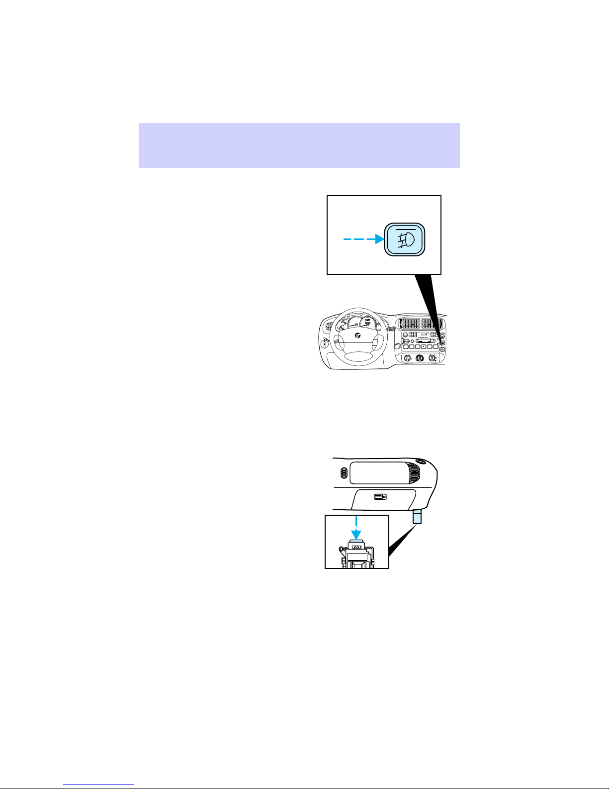
Foglamps
Push the button to activate the
foglamps. The indicator light will
turn on. The foglamps can be
turned on only when the low beam
headlamps are on. Push the button
again to turn off.
Audio system
Refer to the Audio Guide for
instructions on how to operate the
audio system.
Fuel pump shutoff switch
Refer to the Roadside
emergencies chapter for
instructions on how to operate the
fuel pump shutoff switch.
60
5
6
70
50
4
oooo
40
80
100
80
120
3
H
140
60
UNLEADED
30
90
FUEL ONLY
40
2
160
C
000000
100
20
180
20
1
110
10
0
0
120
km/h
km/h
F
RPMx1000
E
OFF
P RND21
ON
OFF
SRS
VOL – PUSH ON
RSM
SEEK
TUNE
SET
ACC
COAST
DISCS
REW
1
CLK
ST
FM 1
AM
BALFADE
BASSTREB
FM
AUTO
PUSH
SET
TAPE CD
EJ
SCAN
DOLBY SYSTEM
FF
COMP5SHUFFLE
SIDE 1-2
2
6
4
3
OFF
LO
A/C
*
MAX
*
HI
A/C
16
Page 17
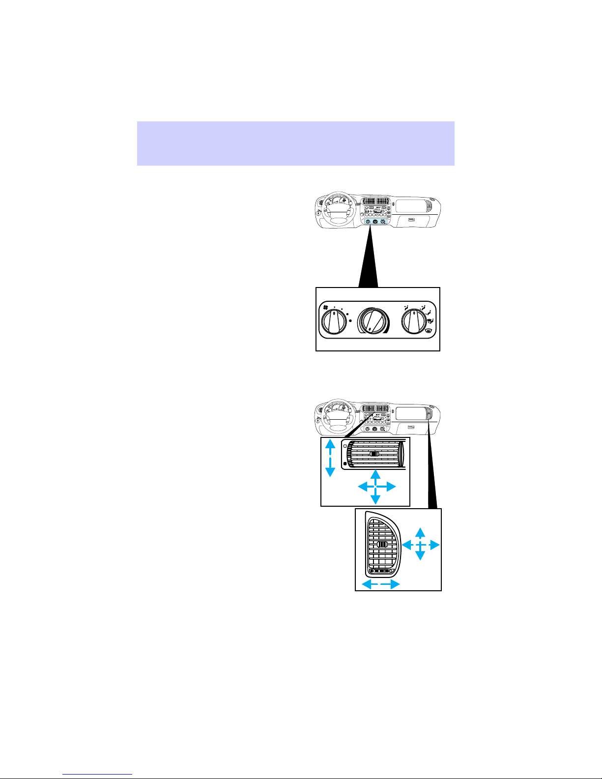
Climate controls
Instrument panel vents
There are four vents on the
instrument panel. These vents are
equipped with dials to adjust the
amount and direction of air passing
through them.
Controls and features
100
5
6
120
80
4
oooo
60
140
3
H
UNLEADED
40
FUEL ONLY
160
2
C
000000
20
180
1
0
0
120
km/h
F
RPMx1000
P RND21
E
OFF
ON
OFF
4
3
H
2
C
1
0
F
E
OFF
ON
OFF
VOL – PUSH ON
CLK
ST
FM 1
AM
BALFADE
BASSTREB
FM
AUTO
PUSH
RSM
SET
ACC
COAST
SRS
60
5
6
70
50
oooo
40
80
100
80
120
140
60
UNLEADED
30
90
FUEL ONLY
40
160
000000
100
20
180
20
110
10
0
120
km/h
RPMx1000
P RND21
RSM
SET
ACC
COAST
SRS
SET
SEEK
TAPECD
EJ
SCAN
DOLBY SYSTEM
TUNE
DISCS
FF
SHUFFLE
REW
COMP
SIDE 1-2
2
5
6
1
4
3
OFF
LO
A/C
*
MAX
*
HI
A/C
OFF
A/C
*
MAX
*
A/C
VOL – PUSH ON
CLK
ST
FM 1
AM
BALFADE
BASSTREB
FM
AUTO
PUSH
SET
SEEK
TAPECD
EJ
SCAN
DOLBY SYSTEM
TUNE
DISCS
FF
SHUFFLE
REW
COMP
SIDE 1-2
2
5
6
1
4
3
OFF
LO
A/C
*
MAX
*
HI
A/C
17
Page 18
Controls and features
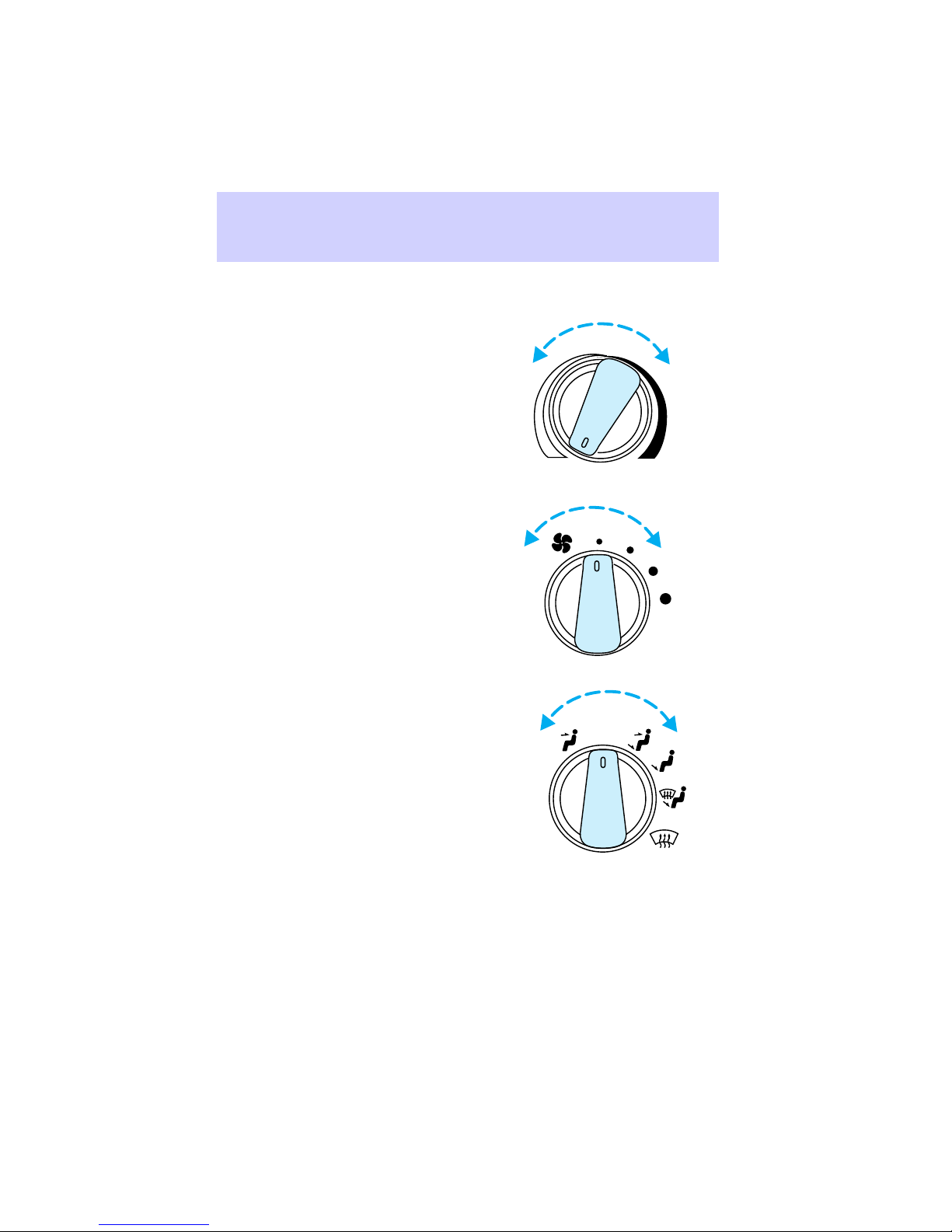
Operating climate controls
• Turn the temperature control to
the desired temperature.
• Turn the fan speed control to
the desired speed.
• Turn the mode control to the
desired airflow position.
OFF
18
A/C
MAX
A/C
Page 19
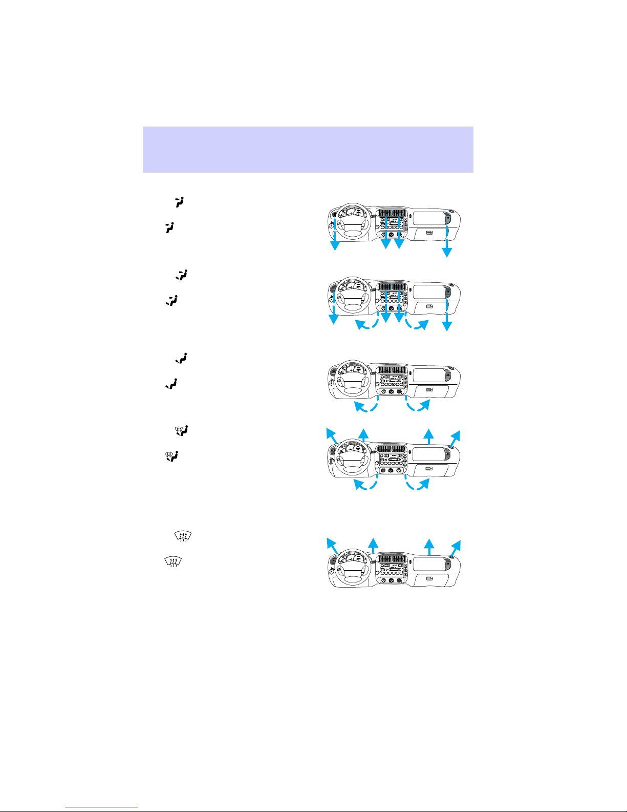
Controlling airflow
Select for air to flow through
these vents:
The position allows outside air
to flow through the instrument
panel vents.
Controls and features
5
6
60
70
50
4
oooo
40
80
100
3
80
120
H
140
UNLEADED
60
30
90
FUEL ONLY
2
C
40
160
000000
100
20
180
20
1
110
10
0
0
F
120
km/h
RPMx1000
P RND21
E
OFF
ON
OFF
VOL – PUSH ON
CLK
ST
FM 1
AM
BALFADE
BASSTREB
FM
AUTO
PUSH
RSM
SET
ACC
COAST
SRS
SET
SEEK
TAPECD
EJ
SCAN
DOLBY SYSTEM
TUNE
DISCS
FF
REW
COMP5SHUFFLE
SIDE 1-2
2
1
6
4
3
OFF
LO
A/C
*
MAX
*
HI
A/C
Select
for air to flow through
these vents:
The position directs outside
air to flow between the panel and
floor vents. The air conditioning
will function provided the outside
temperature is above 10°C (50°F).
Select
for air to flow through
these vents:
The position directs outside
air to flow through the floor vents.
Select
for air to flow through
these vents:
The position directs outside
air to flow through the floor vents
and the windshield defroster vents.
The air conditioning will function
to dehumidify the windows
provided the outside temperature
is above 10°C (50°F).
Select
for air to flow through
these vents:
The position directs outside
air to flow through the windshield
defroster vents. The air
conditioning will function to
dehumidify the windows provided
the outside temperature is above
10°C (50°F).
5
6
60
70
50
4
oooo
40
80
100
3
80
120
H
140
UNLEADED
60
30
90
FUEL ONLY
2
C
40
160
000000
100
20
180
20
1
110
10
0
0
F
200
km/h
RPMx1000
P RND21
E
OFF
ON
OFF
4
3
H
2
C
1
0
F
E
OFF
ON
OFF
4
3
H
2
C
1
0
F
E
OFF
ON
OFF
4
3
H
2
C
1
0
F
E
OFF
ON
OFF
VOL – PUSH ON
CLK
ST
FM 1
AM
BALFADE
BASSTREB
FM
AUTO
PUSH
RSM
SET
ACC
COAST
SRS
5
6
60
70
50
oooo
40
80
100
80
120
140
UNLEADED
60
30
90
FUEL ONLY
40
160
000000
100
20
180
20
110
10
0
200
km/h
RPMx1000
P RND21
RSM
SET
ACC
COAST
SRS
5
6
60
70
50
oooo
40
80
100
80
120
140
UNLEADED
60
30
90
FUEL ONLY
40
160
000000
100
20
180
20
110
10
0
200
km/h
RPMx1000
P RND21
RSM
SET
ACC
COAST
SRS
5
6
60
70
50
oooo
40
80
100
80
120
140
UNLEADED
60
30
90
FUEL ONLY
40
160
000000
100
20
180
20
110
10
0
0
200
km/h
RPMx1000
P RND21
RSM
SET
ACC
COAST
SRS
SET
SEEK
TAPECD
EJ
SCAN
DOLBY SYSTEM
TUNE
DISCS
FF
REW
COMP5SHUFFLE
SIDE 1-2
2
1
6
4
3
OFF
LO
A/C
*
MAX
*
HI
A/C
VOL – PUSH ON
CLK
ST
FM 1
AM
BALFADE
BASSTREB
FM
AUTO
PUSH
SET
SEEK
TAPECD
EJ
SCAN
DOLBY SYSTEM
TUNE
DISCS
FF
REW
COMP5SHUFFLE
SIDE 1-2
2
1
6
4
3
OFF
LO
A/C
*
MAX
*
HI
A/C
VOL – PUSH ON
CLK
ST
FM 1
AM
BALFADE
BASSTREB
FM
AUTO
PUSH
SET
SEEK
TAPECD
EJ
SCAN
DOLBY SYSTEM
TUNE
DISCS
FF
REW
COMP5SHUFFLE
SIDE 1-2
2
1
6
4
3
OFF
LO
A/C
*
MAX
*
HI
A/C
VOL – PUSH ON
CLK
ST
FM 1
AM
BALFADE
BASSTREB
FM
AUTO
PUSH
SET
SEEK
TAPECD
EJ
SCAN
DOLBY SYSTEM
TUNE
DISCS
FF
REW
COMP5SHUFFLE
SIDE 1-2
2
1
6
4
3
OFF
LO
A/C
*
MAX
*
HI
A/C
19
Page 20
Controls and features
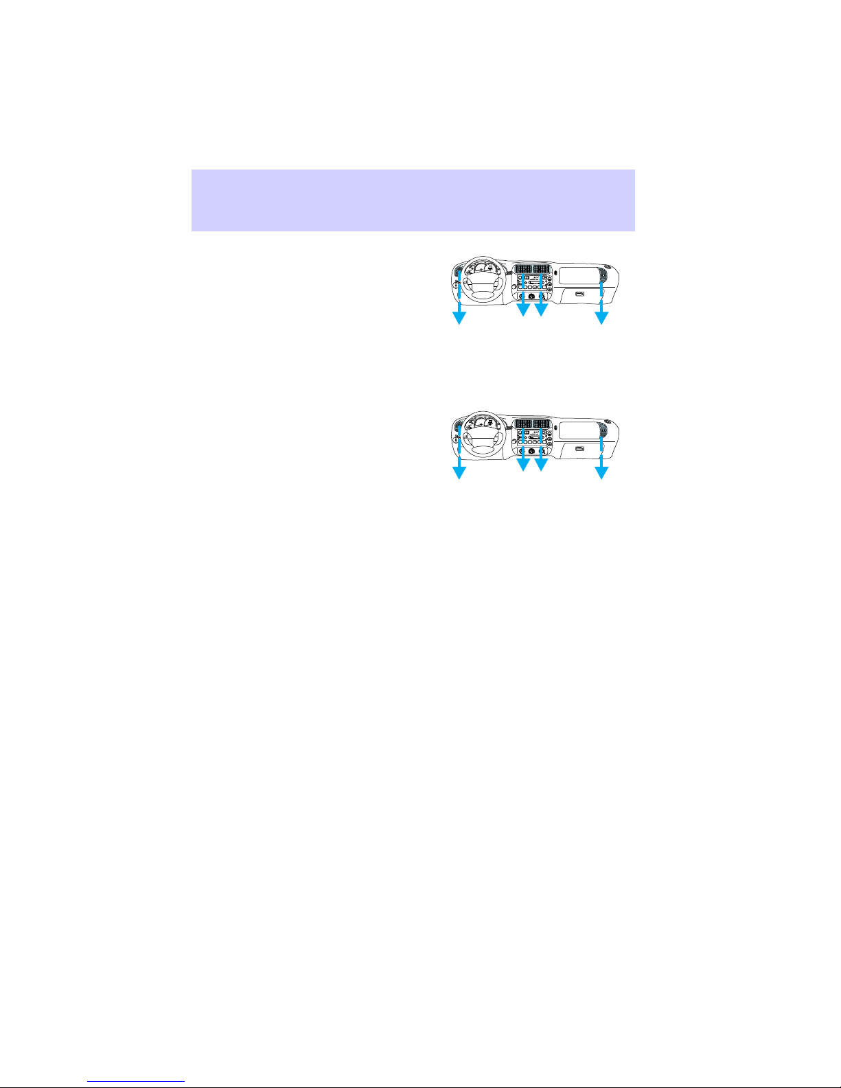
Select A/C for air to flow through
these vents:
The A/C mode directs outside air
conditioned air to flow through the
instrument panel vents. The A/C
mode can be used for heating,
ventilating or air conditioning. The
A/C mode only functions if the
outside temperature is above 10°C
(50°F).
Select MAX A/C for air to flow
through these vents:
The MAX A/C mode recirculates
the air and directs it to flow
through the instrument panel
vents. The MAX A/C mode can be
used for air conditioning or
heating. This mode is noisier but
more economical than A/C mode.
The MAX A/C mode only functions
if the outside temperature is above
10°C (50°F).
Select the OFF position for all
climate control functions to cease.
The outside inlet door will close
and the fan is shut off.
Drive with the climate control
system on (in either the heating or
air conditioning mode) to reduce
humidity in your vehicle.
❄
❄
60
5
6
70
50
4
oooo
40
80
100
80
120
3
H
140
60
UNLEADED
30
90
FUEL ONLY
40
160
2
C
000000
100
20
180
20
1
110
10
0
0
200
km/h
F
RPMx1000
P RND21
E
OFF
ON
OFF
3
H
2
C
1
0
F
E
OFF
ON
OFF
VOL – PUSH ON
CLK
ST
FM 1
AM
BALFADE
BASSTREB
FM
AUTO
PUSH
RSM
SET
ACC
COAST
SRS
60
5
6
70
50
4
oooo
40
80
100
80
120
140
60
UNLEADED
30
90
FUEL ONLY
40
160
000000
100
20
180
20
110
10
0
200
km/h
RPMx1000
P RND21
RSM
SET
ACC
COAST
SRS
SET
SEEK
TAPECD
EJ
SCAN
DOLBY SYSTEM
TUNE
DISCS
FF
REW
COMP5SHUFFLE
SIDE 1-2
2
1
6
4
3
OFF
LO
A/C
*
MAX
*
HI
A/C
VOL – PUSH ON
CLK
ST
FM 1
AM
BALFADE
BASSTREB
FM
AUTO
PUSH
SET
SEEK
TAPECD
EJ
SCAN
DOLBY SYSTEM
TUNE
DISCS
FF
REW
COMP5SHUFFLE
SIDE 1-2
2
1
6
4
3
OFF
LO
A/C
*
MAX
*
HI
A/C
20
Page 21

Maximum heating
Set mode control to , turn
temperature control to maximum
heat (red) and set fan speed
control to maximum.
Maximum cooling
Set mode control to MAX A/C, turn
temperature control to maximum
cool (blue) and set fan speed
control to maximum.
Ventilating with outside air
Set mode control to , turn the
temperature control to the desired
temperature and turn fan speed
control to desired position.
Maximum windshield defrosting
Set mode control to , turn
temperature control to maximum
heat (red) and set fan speed
control to maximum speed.
• To prevent air intake restriction,
remove any snow, ice or leaves
from the air intake area located
directly under the windshield.
Controls and features
21
Page 22
Controls and features
STEERING COLUMN
CONTROLS
60
5
6
70
50
4
3
H
UNLEADED
FUEL ONLY
2
C
1
0
F
E
RPMx1000
40
30
40
20
20
10
0
0
km/h
P RND21
60
oooo
100
80
000000
80
120
140
H
90
160
L
100
180
110
120
H
- +
L
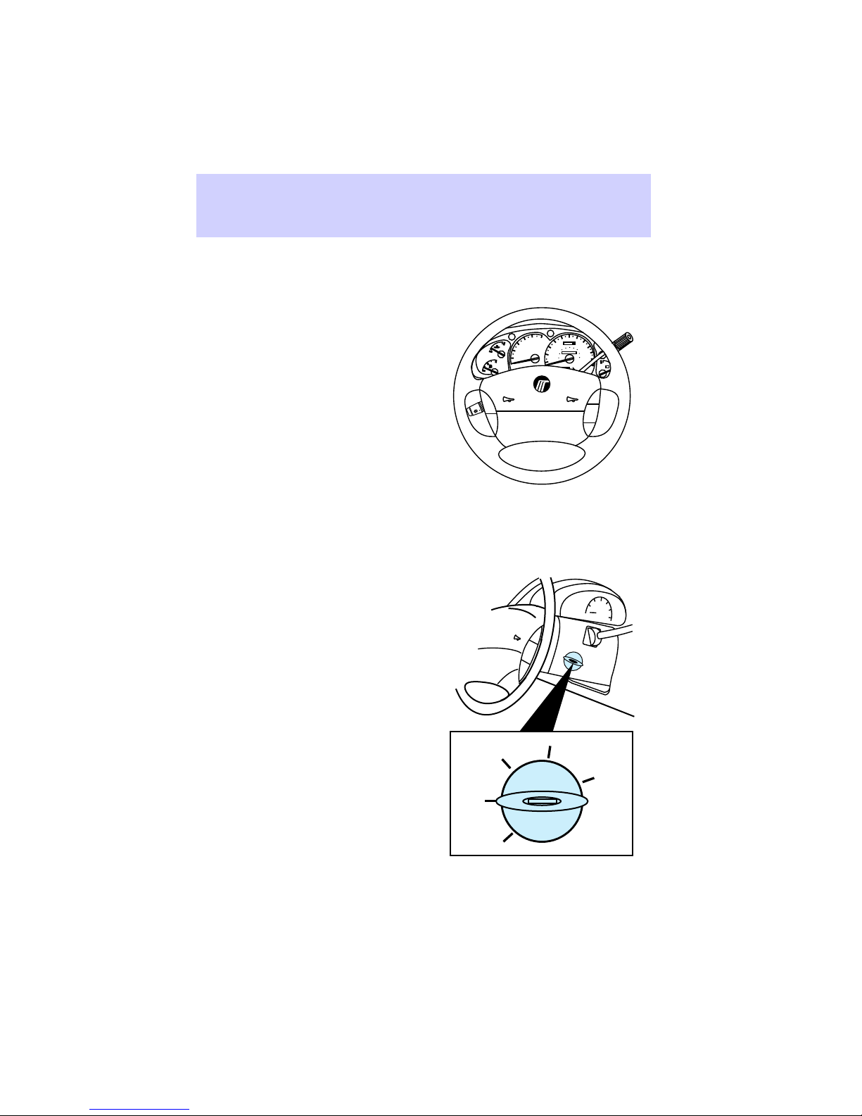
Positions of the ignition
ACCESSORY allows electrical
accessories such as radio and
wipers/washer to operate while the
engine is not running.
LOCK locks the steering wheel
and gearshift lever.
OFF shuts off the ignition and
accessories and allows the
gearshift lever and steering wheel
to move.
ON tests the warning lights. The
key remains here when engine is
running.
START cranks the engine. The key
returns to ON when released.
LOCK
ON
OFF
OFF
RSM
SET
ACC
SRS
COAST
ON
START
22
ACCESSORY
Page 23
Speed control
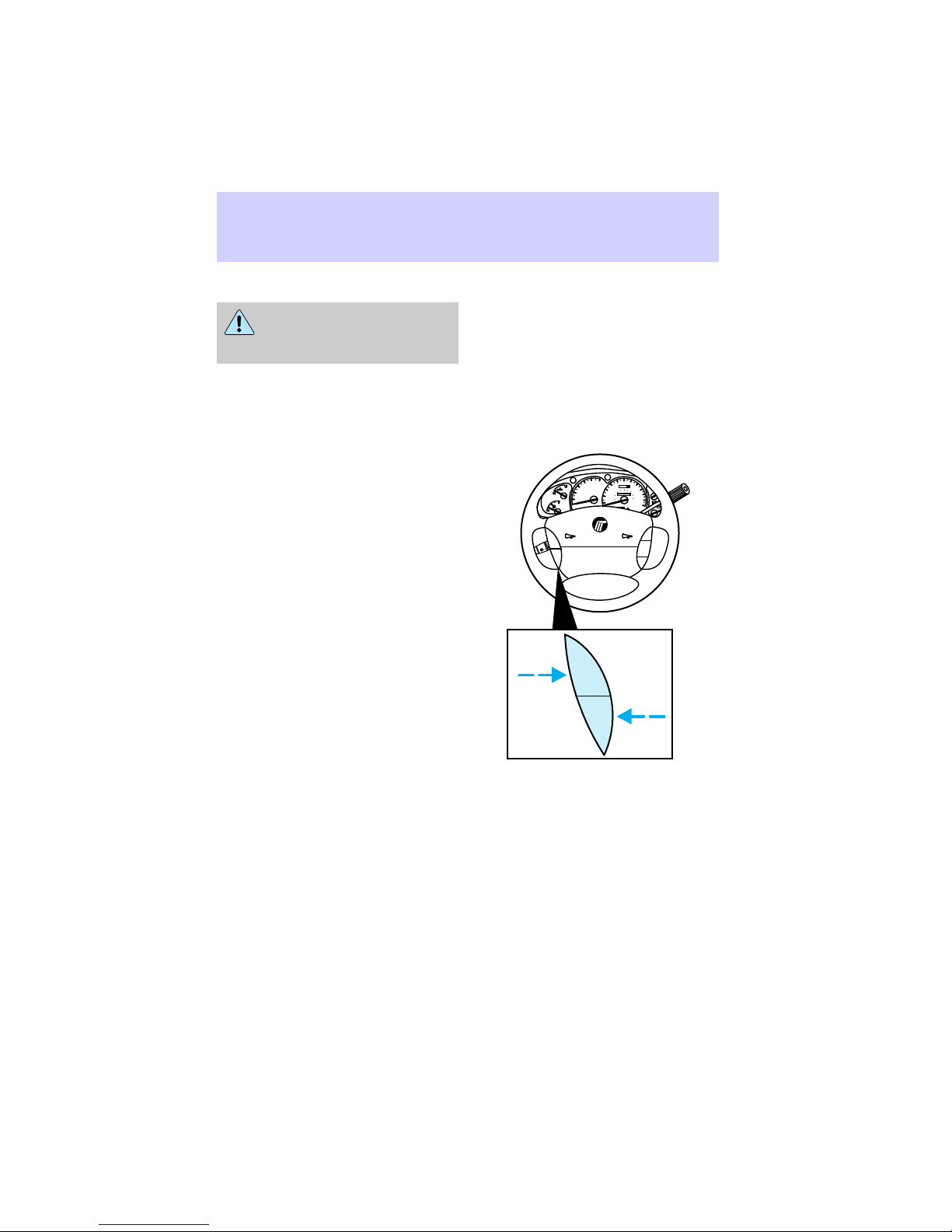
Do not shift the
transmission into N with
the speed control on.
Speed control maintains vehicle
speed automatically at or above
48km/h (30 mph) using the control
switches.
Press ON to turn speed control on.
SPEED
will illuminate in the
CONT
instrument cluster.
Press OFF to turn speed control
off. When turned off, the
previously programmed set speed
will be erased.
Controls and features
5
60
6
70
50
4
oooo
40
80
100
80
3
H
2
C
1
0
F
E
ON
OFF
120
140
60
UNLEADED
30
H
P RND21
SRS
90
40
160
000000
L
100
20
180
20
110
10
0
120
km/h
H
- +
L
RSM
SET
ACC
COAST
FUEL ONLY
RPMx1000
ON
OFF
23
Page 24
Controls and features
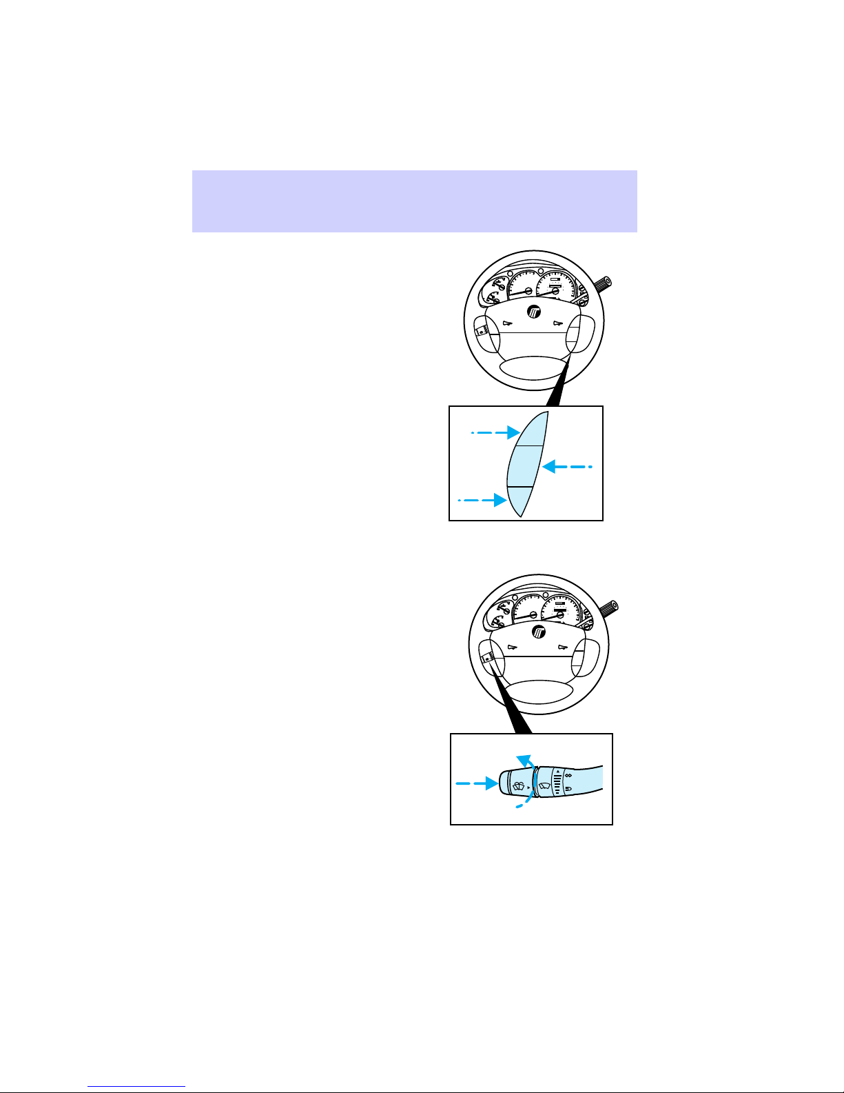
Press SET ACCEL (with speed
control turned ON) to set speed.
Hold SET ACCEL to increase
speed. Press and release once to
increase speed in 1.6 km/h (1
mph) increments.
Press COAST to decrease speed.
Press RSM to resume speed.
Depressing the brake pedal will
cancel the speed control.
Wiper/washer controls
Push the end to activate the
washer. Push end once for a single
wipe. Push and hold for a constant
cycle.
Turn the dial to adjust wiper
speed.
5
6
60
70
50
4
oooo
40
80
100
3
80
UNLEADED
FUEL ONLY
RPMx1000
P RND21
SRS
120
140
60
30
H
90
40
160
000000
L
100
20
180
20
110
10
0
120
km/h
H
- +
L
RSM
SET
ACC
COAST
H
2
C
1
0
F
E
ON
OFF
RSM
SET
ACCEL
COAST
5
6
60
70
50
4
oooo
40
80
100
3
80
UNLEADED
FUEL ONLY
RPMx1000
P RND21
SRS
120
140
60
30
H
90
40
160
000000
L
100
20
180
20
110
10
0
120
km/h
H
- +
L
RSM
SET
ACC
COAST
H
2
C
1
0
F
E
ON
OFF
24
Page 25
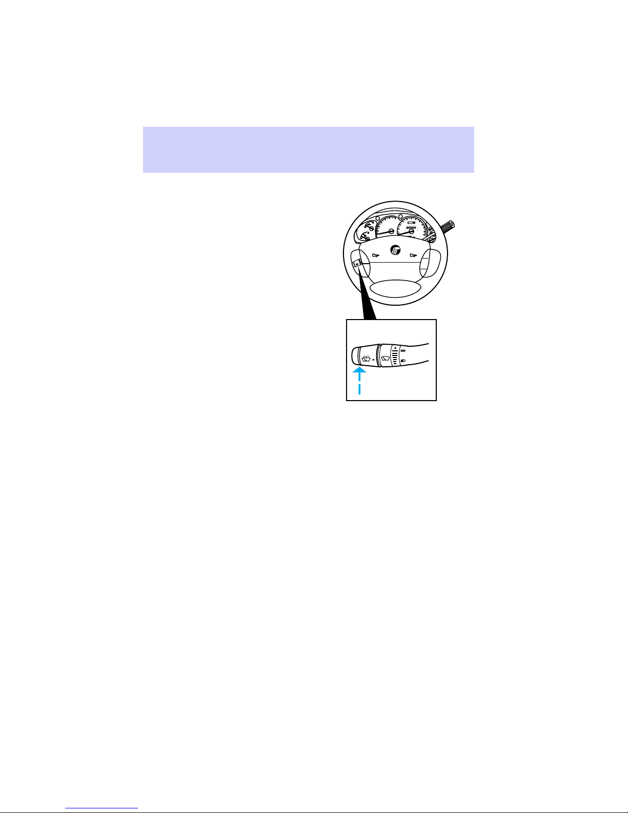
Activating high beams
Push the lever forward to activate
the high beam lamps. Pull the
lever towards you to activate the
“flash to pass” function.
Push the lever down to activate
the left turn signal.
Push the lever up to activate the
right turn signal.
Controls and features
5
6
60
70
50
4
oooo
40
80
100
3
80
UNLEADED
FUEL ONLY
RPMx1000
P RND21
SRS
120
140
60
30
H
90
40
160
000000
L
100
20
180
20
110
10
0
120
km/h
H
- +
L
RSM
SET
ACC
COAST
H
2
C
1
0
F
E
ON
OFF
25
Page 26
Controls and features
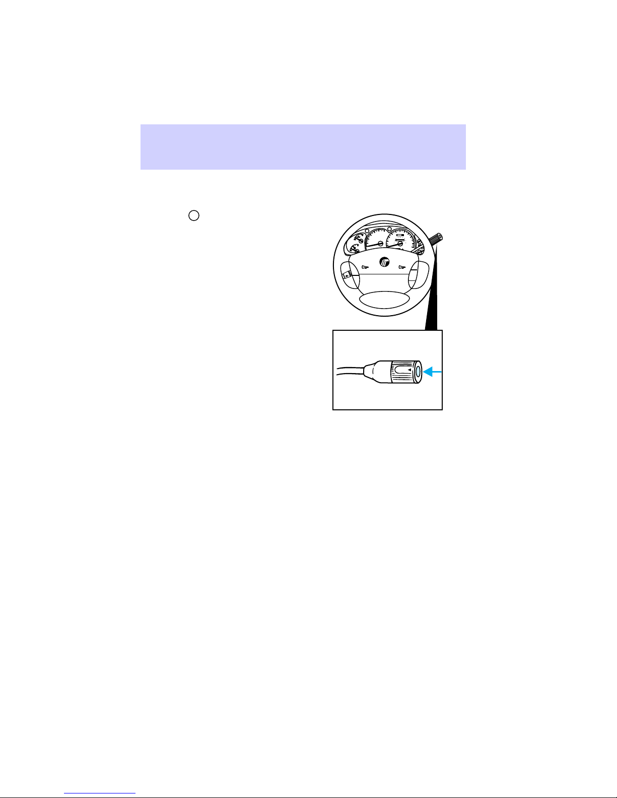
Overdrive control
Activating overdrive
Overdrive
position for the best fuel economy
and will remain on until overdrive
is deactivated.
The overdrive function allows
automatic upshifts to 2nd, 3rd, and
4th gear.
Deactivating overdrive
Press the transmission control
switch on the end of the gearshift
lever. The transmission control
indicator light (TCIL)
illuminate on the instrument
cluster.
Transmission will operate in gears
1-3. To return to normal overdrive
mode, press the transmission
control switch again.
off.
When starting your vehicle, the
transmission will automatically
return to normal overdrive mode.
Deactivate overdrive when:
• driving with a heavy load
• driving in hilly areas
• additional engine braking is
desired
D
is the normal drive
O/D
OFF
O/D
OFF
will
will turn
5
6
60
70
50
4
oooo
40
80
100
3
80
UNLEADED
FUEL ONLY
RPMx1000
P RND21
SRS
120
140
60
30
H
90
40
160
000000
L
100
20
180
20
110
10
0
120
km/h
H
- +
L
RSM
SET
ACC
COAST
O/D
ON/OFF
H
2
C
1
0
F
E
ON
OFF
26
Page 27
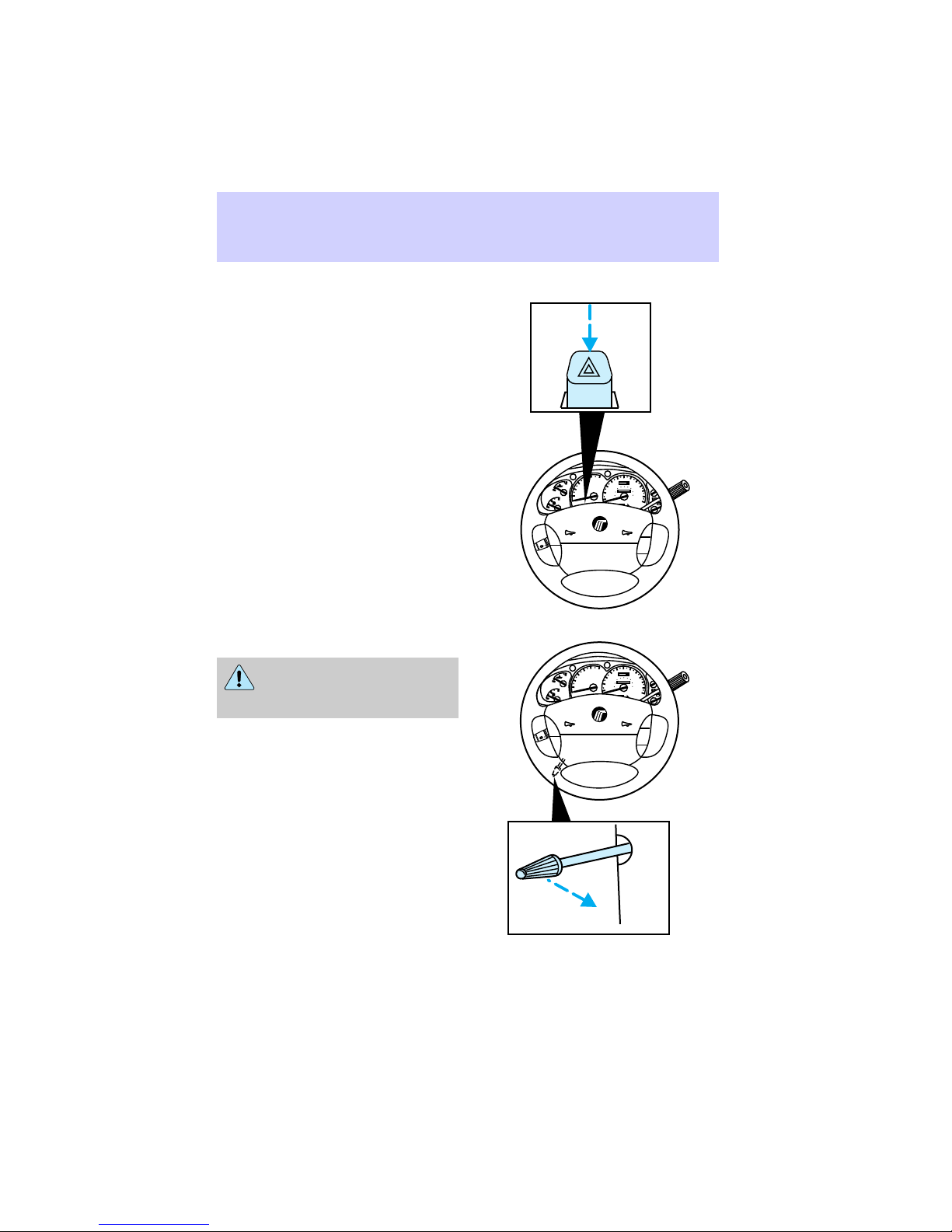
Hazard flasher
Push the hazard flasher button.
The button will pop out and the
lamps will begin to flash.
To stop the flashers, push the
flasher button again.
Tilt steering
Never adjust the steering
column while the vehicle is
moving.
Pull the tilt steering lever towards
you and move the wheel to the
desired position.
Controls and features
5
6
60
70
50
4
oooo
40
80
100
3
80
H
2
C
1
0
F
E
ON
OFF
3
H
2
C
1
0
F
E
ON
OFF
120
140
60
UNLEADED
30
H
SRS
5
SRS
20
10
0
P RND21
6
30
20
10
0
P RND21
90
40
160
000000
L
100
180
20
110
120
km/h
H
- +
L
RSM
SET
ACC
COAST
60
70
50
oooo
40
80
100
80
120
140
60
H
90
40
160
000000
L
100
180
20
110
120
km/h
H
- +
L
RSM
SET
ACC
COAST
FUEL ONLY
RPMx1000
4
UNLEADED
FUEL ONLY
RPMx1000
27
Page 28
Controls and features
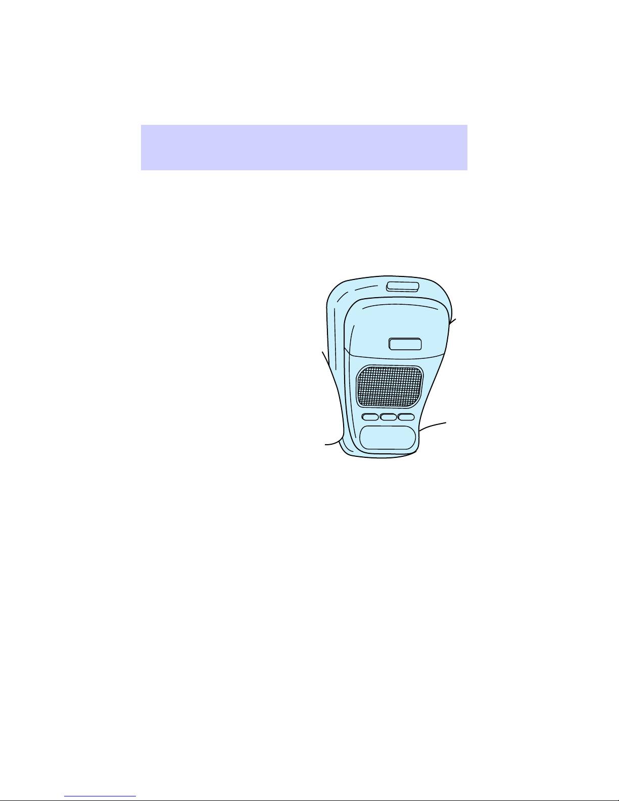
OVERHEAD CONTROLS
Overhead console (if equipped)
The console includes:
• compass/temperature display
• map lamps
• storage compartment
• garage door opener actuator
• moon roof control (if equipped)
OPEN
GARAGE
LAMP MODE LAMP
28
Page 29
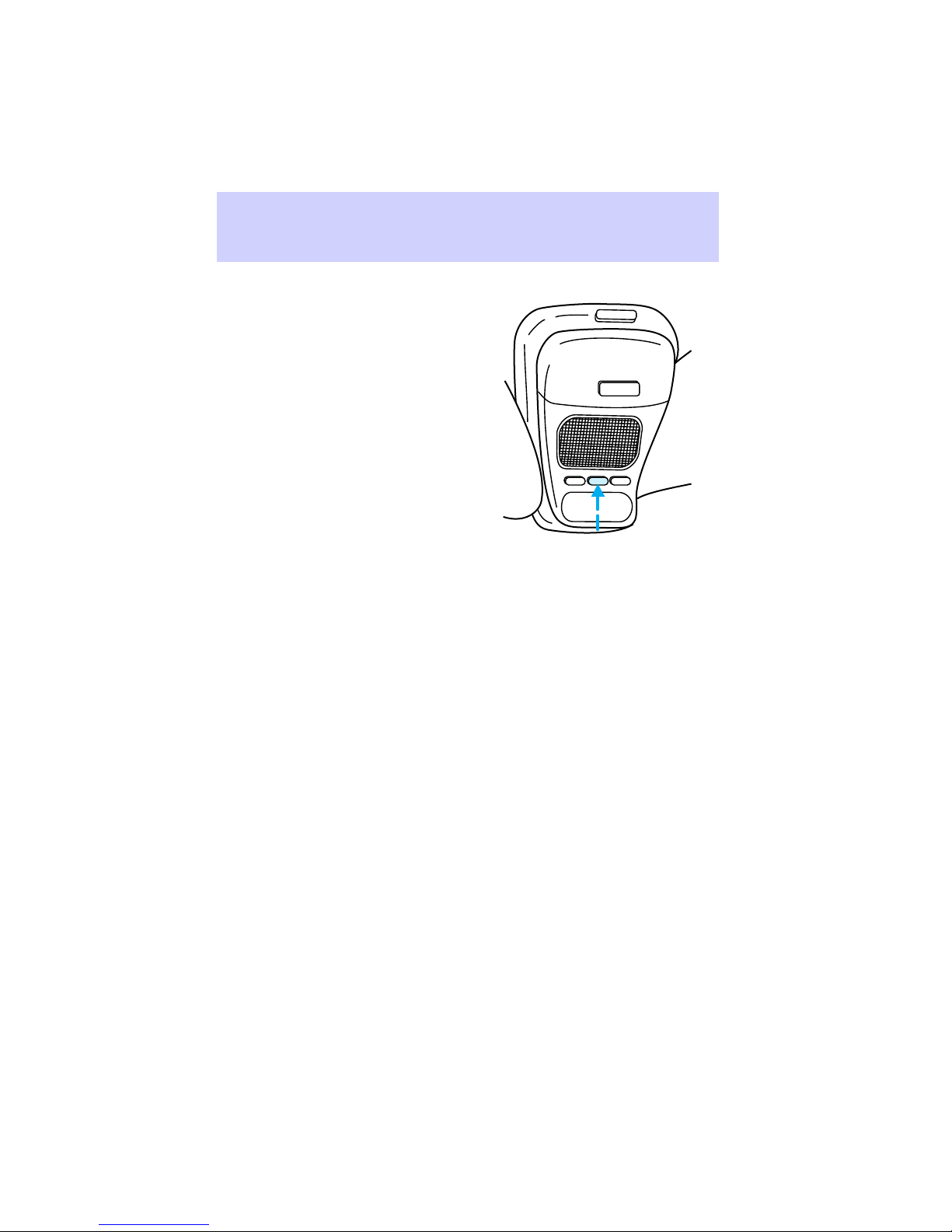
Compass/temperature display
Press the MODE button (with the
ignition key in the ON position) to
switch between the following
features:
• display off
• temperature in C (Celsius) and
compass
• temperature in F (Farenheit)
and compass
If the outside temperature is below
4°C (39°F), the word ICE will flash
alternately with the temperature
for one minute.
Compass accuracy can be affected
when driving by large buildings,
bridges, power lines, and powerful
antennas. Compass accuracy can
also be affected by magnetic
objects placed in or on the vehicle.
There are two types of compass
adjustments: zone and calibration.
Controls and features
OPEN
GARAGE
LAMP MODE LAMP
73° NW
29
Page 30
Controls and features
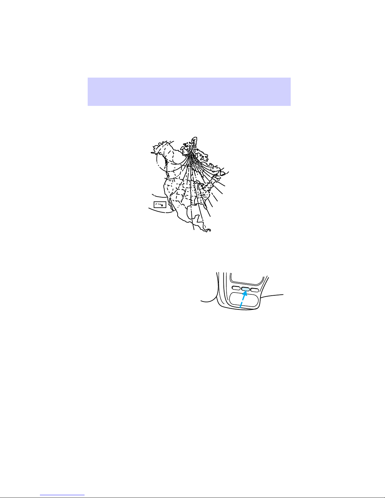
Compass zone adjustment
1
2
3
4
5
1. Determine which zone of the
country you live in by referring to
the zone map.
2. Press and hold the MODE
button until VAR appears in the
display; then release. The display
will show the current zone number.
3. Press the MODE button until
the desired zone number appears.
Wait three seconds. The display
will flash and then return to
normal operation. Zone is now
updated.
Compass calibration adjustment
Perform this adjustment in an
open area free from steel
structures and high voltage lines.
6
78
10
9
15
11
14
13
12
LAMP
MODE
9 VAR
LAMP
30
Page 31

1. Press and hold the MODE
button until CAL appears in the
display (approximately eight
seconds); then release.
2. Drive the vehicle slowly (less
than 5 km/h/3 mph) in circles until
the CAL indicator turns off (2-3
complete circles).
Map lamps
Press either the driver or
passenger button to turn map
lamps on or off.
Storage compartment (if
equipped)
Press the OPEN button to open
the storage compartment. The
door will open slightly and can be
moved to full open.
Controls and features
LAMP
MODE
LAMP
CAL
OPEN
GARAGE
MODELAMP LAMP
OPEN
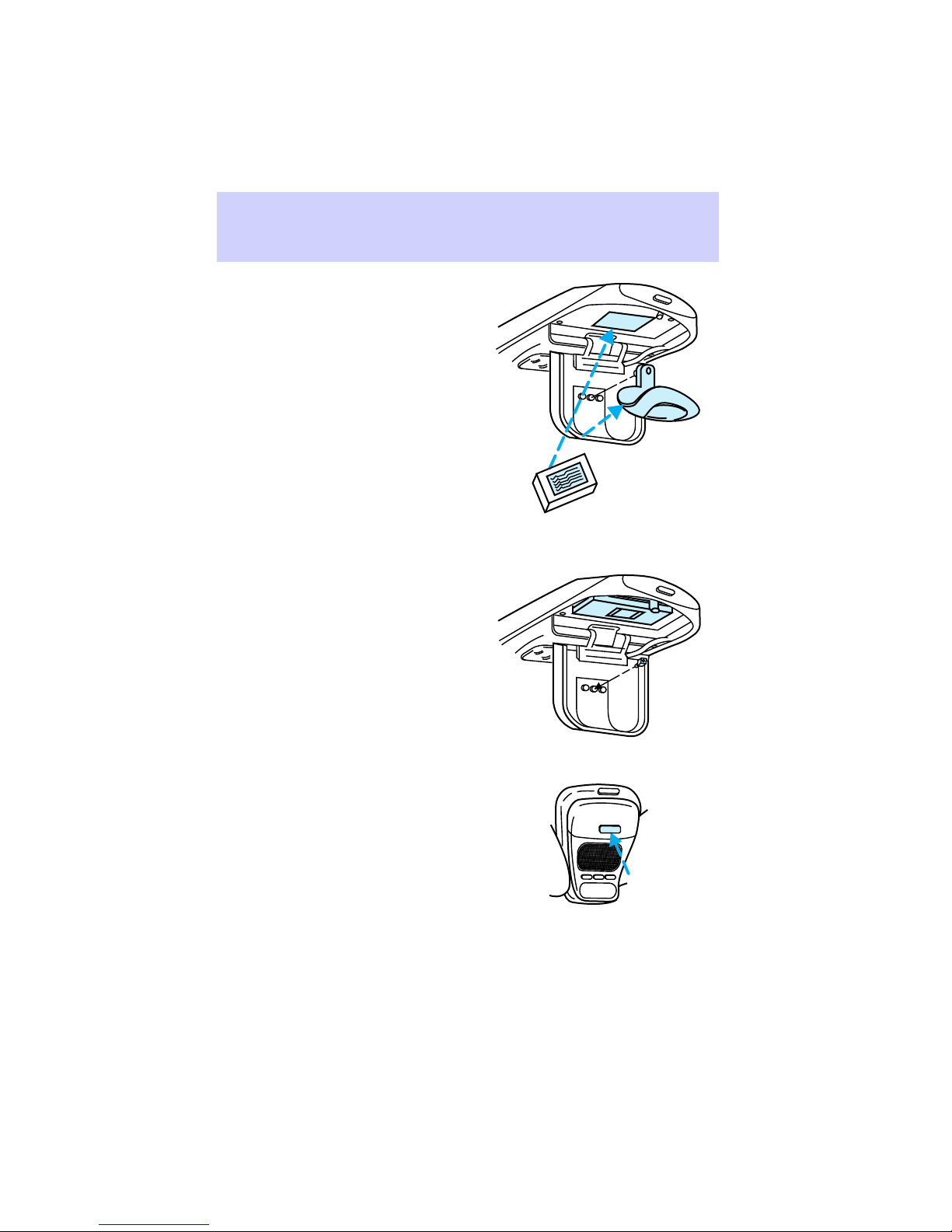
Installing a garage door opener
The storage compartment can be
converted to activate a variety of
aftermarket garage door openers.
LAMP
MODE
LAMP
31
Page 32
Controls and features
1. Remove storage clip from door.
2. Place Velcro™ hook onto side of
aftermarket transmitter opposite of
actuator button.
3. Place transmitter into storage
compartment, button down.
4. Place the provided height
adapters onto the back side of the
GARAGE button as needed.
5. Press the GARAGE button to
activate the transmitter.
32
OPEN
GARAGE
LAMP
MODE
LAMP
Page 33

Moon roof (if equipped)
Press and hold bottom portion of
moon roof switch to open.
Press and hold top portion of
moon roof switch to close.
To raise the rear of the moon roof,
close the moon roof and press top
of rocker switch again. Press
bottom of rocker switch to close it.
Autolamp delay system and
automatic dimming mirror (if
equipped)
Autolamp
The autolamp sets the headlamps
to turn on and off automatically.
You can set the autolamp to:
• turn on the lamps automatically
at night
• turn off the lamps automatically
during daylight
• keep the lamps on for up to
three minutes after you turn the
key to OFF
Setting autolamp
1. Make sure the headlamp switch
is in the OFF position. If the
headlamp switch is on, you
override the autolamp.
2. Turn the ignition key to ON or
start your vehicle.
Controls and features
MODELAMP LAMP
33
Page 34

Controls and features
3. Slide the delay slide knob to the
center of travel. The further you
move the knob to the right, the
longer the headlamps stay on after
the ignition is turned to the OFF
position. The autolamp will keep
the headlamps on for a maximum
of three minutes after the ignition
is turned off.
4. The autolamp automatically
turns the lamps on and off.
Automatic dimming feature
The autolamp/automatic dimming
mirror is equipped with an
automatic dimming feature. This
feature will change from the
normal state to the non-glare
‘‘active’’ state when bright lights
(glare) reach the mirror. When the
mirror detects bright light from the
front or behind, it will adjust
automatically to minimize glare.
The automatic dimming feature is
active when the ignition is turned
to the ON position.
When active, the mirror senses
bright light (glare) from the front
and rear and automatically adjusts
itself to minimize glare.
AUTOLAMP
RELAY
OFF MAX
34
Page 35

DOOR MOUNTED CONTROLS
Power windows
Driver side control
Press and hold rocker switch to
close driver window.
Press and release rocker switch for
partial window movement.
The driver side power window has
a one touch down feature. When
the AUTO switch is fully pressed,
the driver side window will move
completely down. This feature can
be canceled by pressing the driver
side power window button again.
Controls and features
DOOR LOCK
U
L
AUTO
WINDOW LOCK
Press rocker switch to open the
passenger window.
Press rocker switch to close the
passenger window.
DOOR LOCK
U
L
AUTO
WINDOW LOCK
35
Page 36
Controls and features
Press rocker switch to open the
rear passenger window(s).
Press rocker switch to close the
rear passenger window(s).
Your vehicle has a power window
lock feature. When the power
window lock feature is enabled,
the passenger and the rear seat
power windows cannot be
operated by passengers.
Press rocker switch to enable
power window lock.
DOOR LOCK
U
L
AUTO
WINDOW LOCK
DOOR LOCK
U
AUTO
L
36
WINDOW LOCK
Page 37

Passenger side control
Press rocker switch to open
window.
Press rocker switch to close
window.
Rear seat passengers
Press rocker switch to open right
rear window.
Press rocker switch to close right
rear window.
Controls and features
DOOR LOCK
LU
WINDOW
Press rocker switch to open left
rear window.
Press rocker switch to close left
rear window.
37
Page 38

Controls and features
Power locks
Driver side
Press U once to unlock all doors
and liftgate.
Press L once to lock all doors and
liftgate.
Passenger side
Press U once to unlock all doors
and liftgate.
Press L once to lock all doors and
liftgate.
DOOR LOCK
U
L
AUTO
WINDOW LOCK
DOOR LOCK
LU
38
WINDOW
Page 39

Rear liftgate
Press rocker switch (key graphic)
once to unlock all doors and
liftgate.
Press opposite side to lock all
doors and liftgate.
Childproof locks for rear doors
When you set these locks, the rear
doors cannot be opened from the
inside. The rear doors can still be
opened from the outside when the
lock knobs are raised.
Controls and features
DOOR LOCK
39
Page 40

Controls and features
Move lever to LOCK position (up)
to set the lock.
Move lever to UNLOCK position
(down) to disengage the lock.
Two-step unlock feature (if
equipped)
This feature allows you to unlock
all vehicle doors with the key.
1. Unlock driver door.
2. Repeat unlock procedure
within 4 seconds. All doors and
40
Page 41

liftgate will unlock when the key
is returned to the vertical
position (position of key before
removal).
This feature can be activated by all
outside locks on vehicles equipped
with keyless entry.
Illuminated entry
Interior lamps illuminate when
either outside front door handle is
lifted, unlocked with the keyless
entry keypad or the UNLOCK
button is pressed on the remote
entry transmitter (see Remote
entry system or Keyless entry
system for further information).
The system will automatically turn
off after 25 seconds or when the
ignition switch is turned to START
or ON position.
The inside lights will not turn off if
you have turned them on with the
dimmer thumbwheel or if any door
is open. However, the battery saver
will turn them off after ten
minutes. See Battery saver for
more information.
Controls and features
41
Page 42

Controls and features
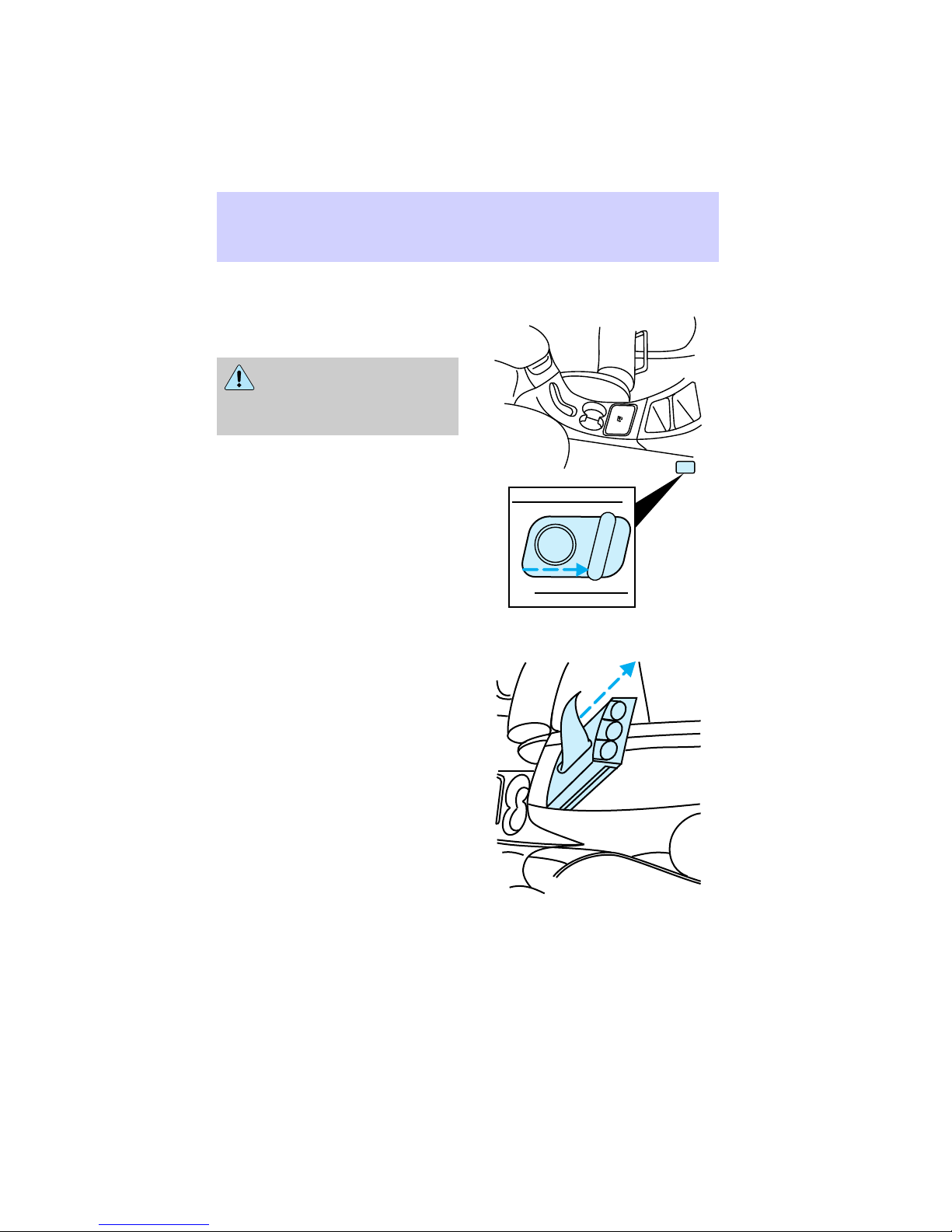
Power mirrors
1. Select driver or passenger
mirror by moving selector lever left
for driver or right for passenger.
2. Move the mirror control knob
until mirror reaches desired
position.
3. Return the selector lever to the
center ‘‘off’’ position.
CONSOLE CONTROLS
Center console
Your vehicle has a center console
that is equipped with the following
features:
• Auxiliary power point
• Utility compartment
• Ashtray
• Cupholders
• Tissue tray
• Utility compartment with
cassette/compact disc storage
and coinholder
• Compact disc changer (if
equipped)
Use only soft cups in the
cupholder. Hard objects
can injure you in a collision.
42
Page 43
Auxiliary power point
This power point is an additional
power source for electrical
accessories.
Do not plug optional
electrical accessories into
the cigarette lighter. Use the
power point.
Replacing the tissue box
1. Lift armrest and slide
coinholder/tissue box out of
console in an upward motion.
2. Replace tissue box.
3. Slide coinholder/tissue tray into
console locating pins at bottom of
tray. Fit in slots in console bracket.
Controls and features
43
Page 44

Controls and features
Rear console (if equipped)
Your vehicle is equipped with a
rear console that includes the
following features:
1. Air vents
2. Audio system controls (refer to
Audio Guide)
3. Rear seat climate control
direction and fan controls
4. Cupholders
44
Page 45

Rear climate controls
Turn the air distribution dial to the
desired airflow position.
Turn the fan speed dial to the
desired position.
Controls and features
– VOLUME + BAND
SEEK
MEMORY
– VOLUME + BAND
SEEK
MEMORY
– VOLUME + BAND
SEEK
MEMORY
45
Page 46

Controls and features
Controlling airflow
Select for air to flow through
these vents:
– VOLUME + BAND
SEEK
MEMORY
Select
for air to flow through
these vents:
Cargo area controls
Cargo cover (if equipped)
Your vehicle is equipped with a
cargo shade that covers the
luggage compartment of your
vehicle.
46
– VOLUME + BAND
SEEK
MEMORY
Page 47

Installing shade
1. Position shade in mounting
brackets as shown (tongue faces
rear of vehicle).
2. Pull end of shade towards you
and hook sides into notches in rear
trim panels.
To avoid possible injury
during a sudden stop or
collision, the cover should be
attached to the brackets when
not in use.
Rewinding shade to regain lost
tension
Over time, the cargo shade may
lose its spring tension. If this
happens, then follow these
instructions to rewind the shade.
You will need the help of another
person.
1. Remove the shade from the side
anchor slots by compressing
telescoping tube. Extend the shade
fully. Make sure smooth grain is
facing you.
2. Wrap the vinyl around the roller
tube twice. Tuck the edges of the
vinyl inside the end cap with each
wrap.
Controls and features
47
Page 48

Controls and features
3. Fold vinyl edges towards center,
making sure that the edges clear
the end cap slots. Use tape or
rubber band to hold the vinyl on
the left side of the roller tube.
4. While holding the vinyl and
roller tube, push in the right end
cap (marked RH) about 6.4 mm
(1/4 inch) to disengage the clutch.
Hold end cap in while turning
roller tube towards you 14 times.
5. Let go of the right end cap. The
clutch should now engage and stop
the shade from losing its spring
tension.
6. Unfold the vinyl and place it
into the end cap slots.
7. Insert the shade into the side
mounting brackets (the opening
for the right mounting bracket is
narrower than the left). Check to
see if the shade operates properly.
Spare tire and jack
Your vehicle is equipped with a
full-size spare tire located behind
the rear bumper. For instructions
on how remove and mount the
spare tire, refer to the Roadside
emergencies section later in this
Owner’s Guide.
48
Page 49
Keyless entry system (if
equipped)
With the keyless entry keypad, you
can:
• lock or unlock the vehicle doors
and liftgate without using the
key.
• arm and disarm the anti-theft
system.
Controls and features
See also Remote entry system and
Anti-theft system later in this
chapter for more information.
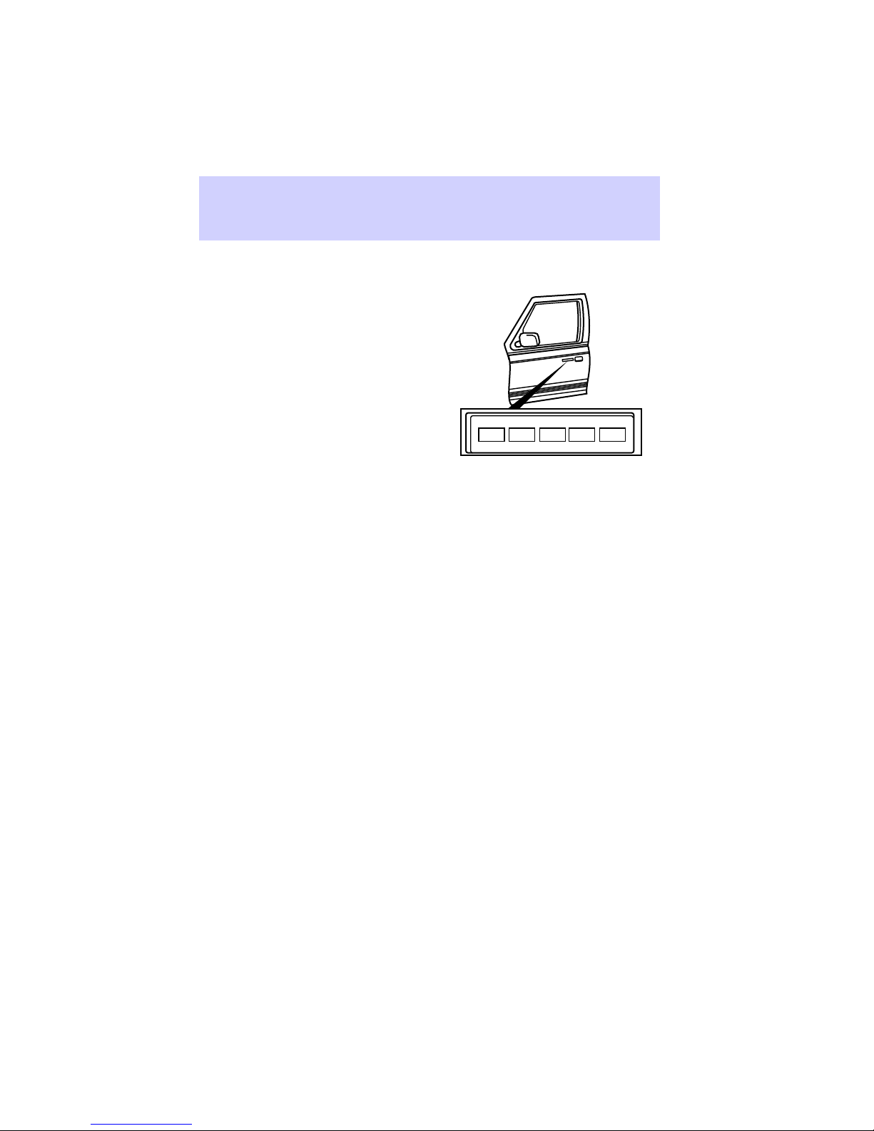
Your vehicle has a factory-set
5-digit code that operates the
keyless entry system. You can also
program your own 5-digit personal
entry code. The factory-set code is
located in:
• the owner’s wallet card in the
glove compartment
• taped to the computer module
Programming personal entry
code
1. Enter factory-set code (keypad
will illuminate when pressed).
2. Press 1/2 within five seconds of
Step 1.
3. Enter your personal 5-digit
code. Enter each digit within five
seconds of the previous one.
Do not set a code that includes
five of the same number or
1•2
5•6 7•8 9•0
3•4
49
Page 50

Controls and features
presents them in a sequential
order.
Press the middle of the buttons
(there is only one switch under
each button).
You can use either code to unlock
your vehicle. If a second personal
code is entered, the module will
erase the old code in favor of the
new code. If you wish to erase
your personal code, use the
following instructions:
Erasing personal code
1. Enter factory-set code.
2. Press 1/2 within five seconds of
Step 1.
3. Wait six seconds.
The system will now only respond
to the factory-set code.
Unlocking the doors with the
keyless entry system
1. Enter either factory-set code or
personal code. Driver door will
unlock and interior lamps will
illuminate.
2. Press 3/4 button within five
seconds of unlocking driver door.
Passenger doors and liftgate will
unlock.
If five seconds expire, you must
re-enter code, then press 3/4
button to unlock all doors.
Locking doors with keyless
entry system
It is not necessary to enter the
factory or personal code prior to
50
Page 51

locking the doors and liftgate. To
lock the doors:
• press 7/8 and 9/0 buttons at the
same time.
This will arm your anti-theft
system; see Arming anti-theft
system with keyless entry and
Anti-theft system later in this
chapter for more details.
Arming anti-theft system with
keyless entry
To arm the anti-theft system:
• press 7/8 and 9/0 buttons at the
same time.
To disarm the anti-theft system:
• enter either the factory-set code
or your personal code.
Doors, liftgate, and liftgate window
must be fully closed for the
anti-theft system to arm. See
Anti-theft system for more details.
Autolock
Autolock is a feature of the keyless
entry system and is enabled at the
factory. Autolock will automatically
lock all doors and liftgate when:
• all vehicle doors, liftgate, and
liftgate window are closed.
• ignition switch is in the ON
position.
• brake pedal is pressed.
• you shift through R (Reverse).
• brake pedal is released.
Controls and features
51
Page 52

Controls and features
Relock
The autolock feature will repeat
when:
• any door is opened and closed.
• the brake pedal is released.
Deactivating autolock
Before following the activation or
deactivation procedures, make sure
that the anti-theft system is not
armed, ignition is off, and all
vehicle doors and liftgate window
are closed.
1. Enter five-digit entry code.
2. Press and hold 7/8 button.
3. Press and release 3/4 button
while holding 7/8 button.
4. Release 7/8 button.
To re-activate autolock, repeat
Steps 1-4.
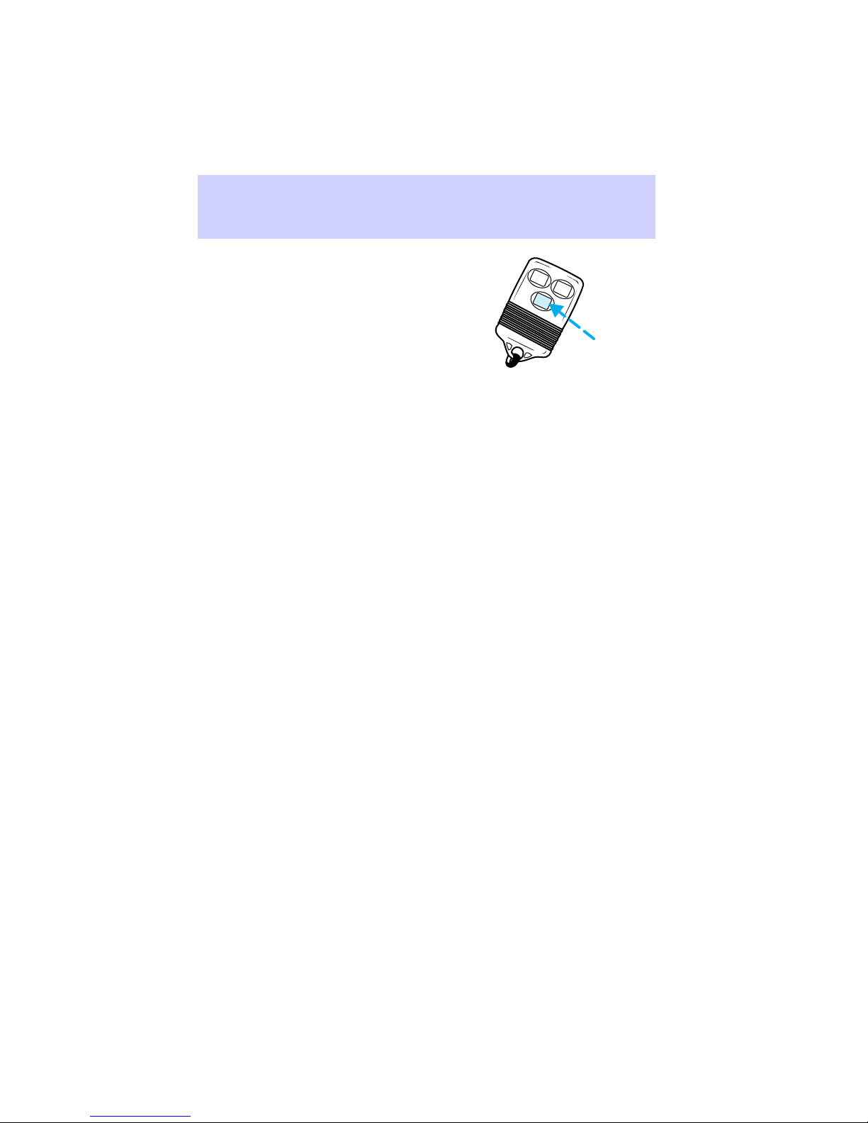
Remote keyless entry system (if
equipped)
The remote entry system allows
you to lock or unlock all vehicle
doors without using a key.
The remote entry system also arms
and disarms the anti-theft system
(see Anti-theft system later in this
chapter for more information).
LOCK
UN
LOCK
PANIC
The remote entry system only
operates with the ignition in the
OFF position.
Your vehicle is equipped with two
transmitters. The system will work
with up to four transmitters.
52
Page 53

Additional transmitters can be
ordered from your dealer.
Unlocking the doors with the
remote entry system
Press UNLOCK button to unlock
driver door. The interior lamps will
illuminate.
Press UNLOCK a second time
within 5 seconds to unlock all
doors and liftgate.
Locking the doors with the
remote entry system
Press the LOCK button to lock all
doors and liftgate.
Press the LOCK button a second
time within 5 seconds to confirm
that all doors and liftgate are
locked.
The doors will lock again, the horn
will chirp, and the lamps will flash.
This will arm your anti-theft
system. If the horn chirps twice, a
door is still ajar and the anti-theft
system will not arm. See Anti-theft
system for more details.
Remote entry personal alarm
The remote entry personal alarm
feature allows you to activate the
alarm. When activated, the horn
will honk and the lights will flash.
Controls and features
LOCK
UN
LOCK
PANIC
LOCK
UN
LOCK
PANIC
53
Page 54
Controls and features
Press the PANIC button to activate
the alarm.
To turn off the alarm, press the
PANIC button again or turn the
ignition key to the ON or ACC
position.
This device complies with Part 15
of the FCC rules. Operation is
subject to the following two
conditions: (1)This device may not
cause harmful interference, and
(2)This device must accept any
interference received, including
interference that may cause
undesired operation.
Replacing the batteries
If you notice a decrease in
operating range, replace the
transmitter batteries. Replacement
batteries can be purchased at most
pharmacies or through your Ford
or Lincoln-Mercury dealer. The
transmitter is powered by two coin
type three-volt lithium 2016
batteries.
The operating range of the remote
entry transmitters can also be
affected by adverse weather
conditions, nearby radio/tv towers,
or large structures around the
vehicle. Typical operating range is
up to 10 meters (33 feet).
Opening the transmitter
Insert and twist a thin coin
between the two halves of the
transmitter; the transmitter will
snap apart.
LOCK
UN
LOCK
PANIC
54
Page 55

When installing new batteries, be
sure to place the positive (+) side
down as marked. Snap the two
halves back together.
Replacing lost transmitters
If a transmitter is lost, take your
vehicle’s transmitter to the dealer
to have the remote entry system
deprogrammed for the lost
transmitter. This will prevent
unauthorized use of the lost
transmitter.
You can purchase additional
transmitters (up to four can be
used) from your dealer. Use the
following instructions to
re-program the key fobs.
Re-programming your key
fob(s)
1. Insert key into ignition.
2. Rotate key to ON five times. DO
NOT START THE ENGINE. Keep
key in ON position the fifth time.
Locks will lock/unlock by
themselves.
3. Push UNLOCK on first key fob.
Doors will lock/unlock to indicate
key fob has been programmed.
4. Repeat Step 3 for each key fob
to be re-programmed.
5. Turn ignition key to OFF. Verify
each transmitter has been
programmed by activating any
button.
Controls and features
55
Page 56

Controls and features
Anti-theft system (if equipped)
When set, the anti-theft system
protects against unauthorized
entry into a locked vehicle.
The ignition switch must be in the
OFF position to arm the anti-theft
system.
Arming the anti-theft system
Use one of the following methods
to arm the system:
• Press the LOCK button on the
remote entry transmitter (with
doors open or closed).
OR
• Open any door and press the
power lock button.
OR
• Press the 7/8 and 9/0 buttons on
the keyless entry keypad (see
Keyless entry system for more
information).
Identifying system indicators
While the system is arming, the
THEFT
30 seconds. After 30 seconds, the
THEFT
If the system is armed with the
doors open,
illuminated until all doors are
closed. After all doors are closed,
it will illuminate for 30 seconds
and then start flashing.
When an unauthorized entry
occurs, the system activates and
will:
indicator will illuminate for
indicator will flash.
THEFT
will stay
56
Page 57

Controls and features
• flash the headlamps, park lamps
and the
THEFT
indicator in the
instrument cluster.
• sound the horn.
• disable vehicle starting.
The flashing exterior lamps and
honking horn will shut off
automatically after about 3
minutes. The lights and horn will
remain off unless another
unauthorized entry is attempted.
However, the vehicle will not start
until the system is properly
disarmed.
How to disarm the system
To cancel an armed system, you
must:
• press the UNLOCK button on
the remote entry transmitter.
OR
• unlock any door with the key.
OR
• turn the ignition switch to the
ON position.
OR
• unlock the doors by entering the
unlock code into the keyless
entry keypad.
How to deactivate a triggered
system
To immediately cancel an activated
system, press the PANIC button on
the remote entry transmitter.
A triggered system can also be
deactivated by following the steps
in How to disarm the system.
57
Page 58

Controls and features
Delayed accessory
Delayed accessory provides power
to operate the power windows and
power moon roof (if equipped) for
10 minutes after the ignition
switch is turned to OFF.
If either front door is opened
during the 10 minute period the
delayed accessory feature is
disabled.
Battery saver
Battery saver is a feature that
automatically shuts off power to
these lights after 40 minutes: glove
box, engine compartment,
overhead console, mirror, courtesy
and interior lamps.
Battery saver prevents the battery
from being drained if these lights
are left on or if a door is not
completely closed. Battery power
is restored if the remote entry
transmitter is used, any door is
opened, the liftgate is opened, or
ignition key is turned to ON.
58
Page 59

FRONT BUCKET SEATS
Adjusting manual seats
Lift to move the seat forward or
backward.
Pull up to recline the seat.
Seating and safety restraints
59
Page 60

Seating and safety restraints
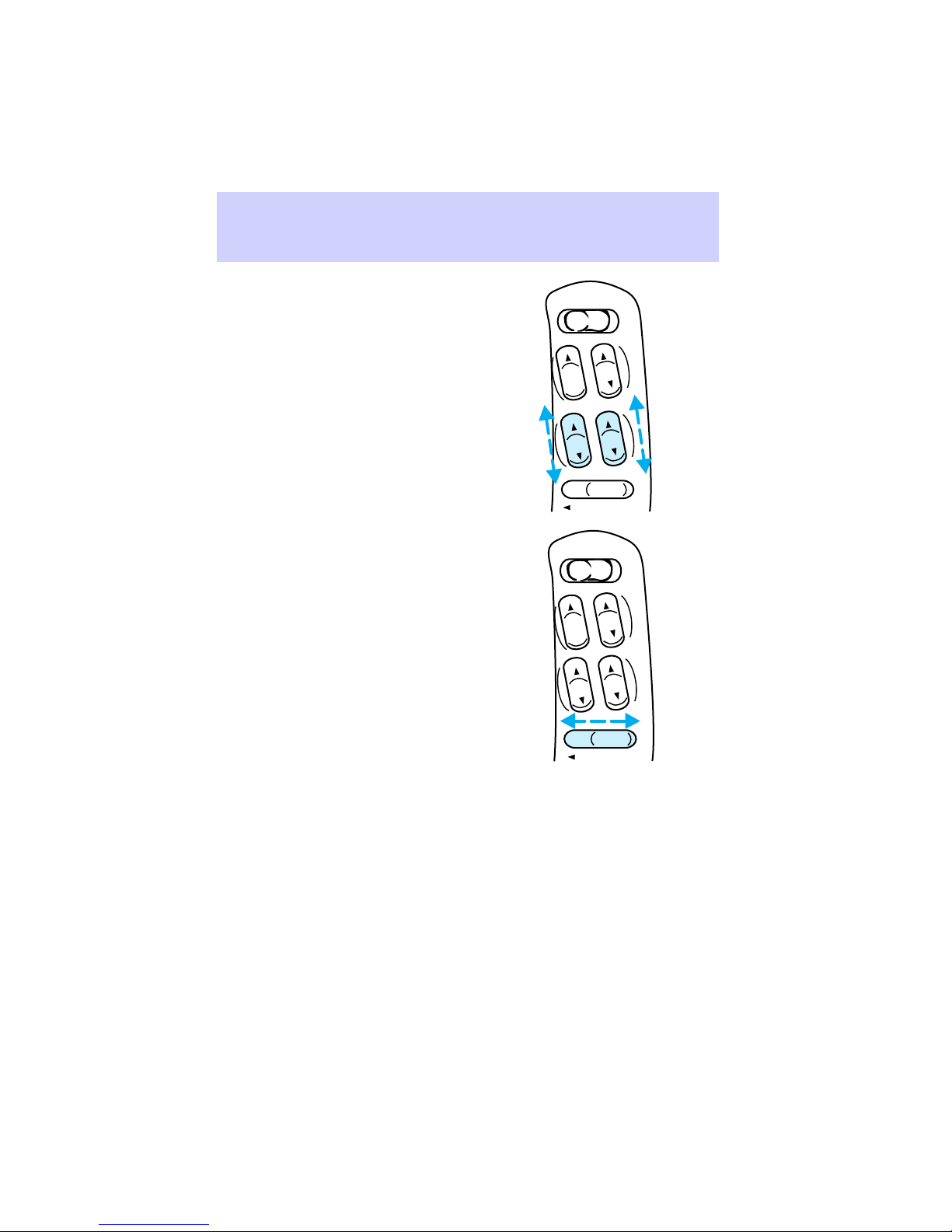
Adjusting power seats (if
equipped)
Pull up to recline the seat.
Press to tilt front and rear of seat
up or down.
60
Page 61

Seating and safety restraints
Press in the desired direction to
raise or lower the seat, or to move
the seat backward or forward.
Push to increase (+) or decrease
(-) lumbar support.
+–
61
Page 62

Seating and safety restraints
Rear seat four-way head
restraints (if equipped)
Push the lock release button to
raise or lower the head restraint.
Push or pull head restraint to
desired position.
Folding rear seat
If your vehicle is equipped with a
built-in child seat, the seatback
cannot be folded down unless the
built-in child seat is fully stowed.
1. Push the lower release handle
downward to unlatch seat back.
2. Rotate seatback downward into
the load floor position.
3. Push down on the top outboard
area of the seatback until you hear
a ‘‘click.’’ The seat is latched in the
load floor position.
62
Page 63

Seating and safety restraints
Return to upright
1. Push downward on upper
outboard corner of seatback and
hold.
2. Lift release handle upward to
unlatch seat.
3. Rotate seatback upward until
seatback latches in the upright
position. You will hear a ‘‘click’’
when seatback locks.
SAFETY RESTRAINTS
PRECAUTIONS
The use of safety belts helps to
restrain you and your passengers
in case of a collision. In most
states and in Canada the law
requires the use of safety belts.
To reduce the risk of
serious injury in a
collision, always drive and ride
with your seatback upright and
the lap belt snug and low across
the hips.
Safety belts must be worn
by all vehicle occupants to
be properly restrained and help
reduce the risk of injury in a
collision.
63
Page 64

Seating and safety restraints
To prevent the risk of
injury make sure children
sit where they can be properly
restrained.
It is extremely dangerous
to ride in a cargo area,
inside or outside of a vehicle. In
a collision, people riding in these
areas are more likely to be
seriously injured or killed.
Do not allow people to
ride in any area of your
vehicle that is not equipped with
seats and safety belts.
Be sure everyone in your
vehicle is in a seat and
using a safety belt properly.
USING THE SAFETY
RESTRAINTS PROPERLY
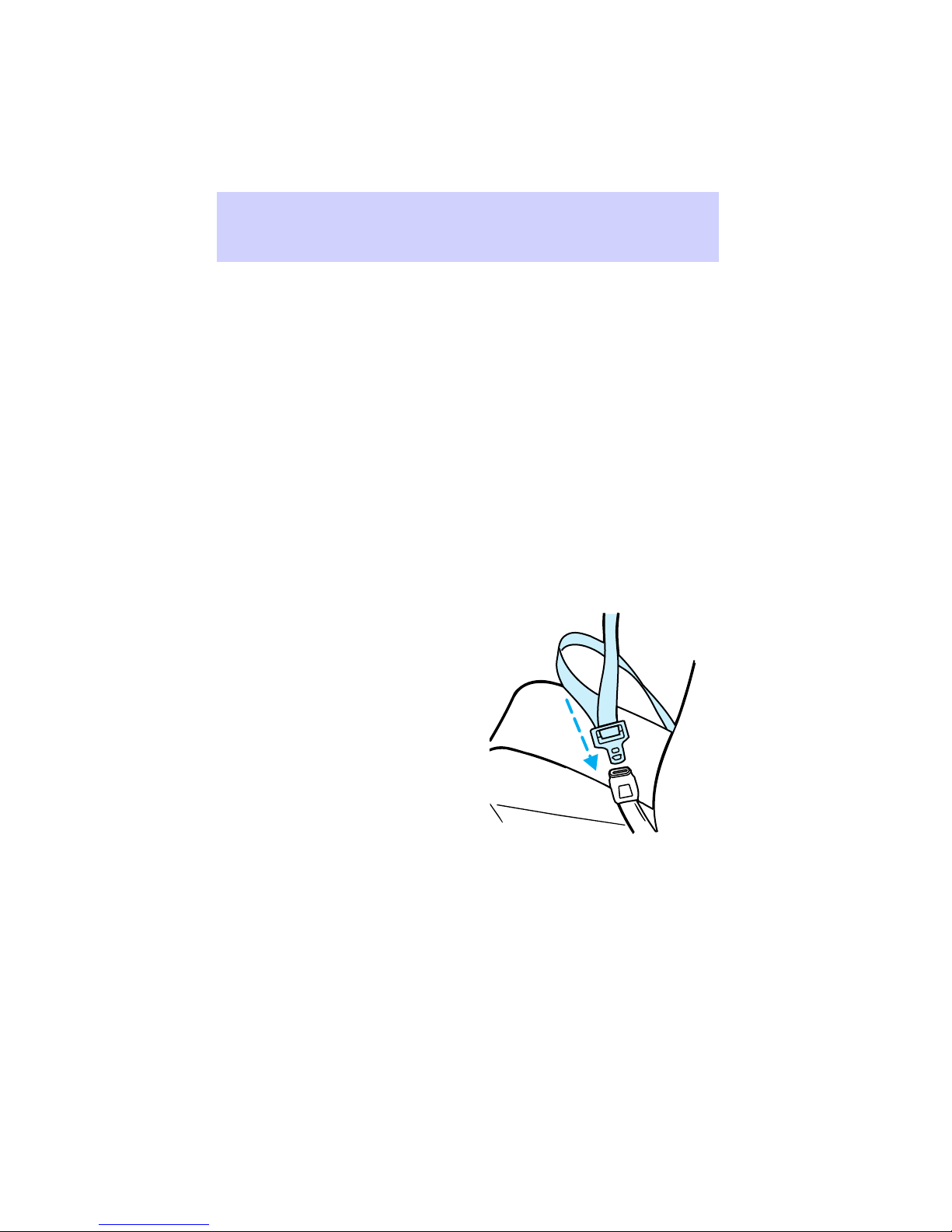
Combination lap and shoulder
belts
1. To connect the safety belt,
insert the tongue into slot in the
buckle.
2. To disconnect the safety belt,
push the red release button and
remove the tongue from the
buckle.
64
PRESS
Page 65

Seating and safety restraints
The outboard safety restraints in
the vehicle are combination lap
and shoulder safety belts. The
front and rear seat passenger
outboard safety belts have the two
types of locking modes described
below:
Vehicle sensitive (Emergency)
locking mode
The vehicle sensitive mode is the
normal retractor mode, allowing
free shoulder belt length
adjustment to your movement and
locking in response to vehicle
movement. For example, if the
driver brakes suddenly, turns a
corner sharply, or the vehicle
receives an impact of 8 km/h (5
mph) or more the combination
safety belts will lock to help
reduce forward movement of the
driver and passengers.
The front seat belt system can also
be made to lock manually by
quickly pulling on the shoulder
belt. Rear seat belts cannot be
made to lock up by pulling quickly
on the belt.
65
Page 66
Seating and safety restraints
Automatic locking mode
In this mode, the shoulder belt is
automatically pre-locked; however,
the belt will still retract to remove
any slack in the shoulder belt.
The automatic locking mode is not
available on the driver safety belt.
When to use the automatic
locking mode
• When a tight lap/shoulder belt
fit is desired.
• Any time a child safety seat is
installed in the vehicle. Refer to
Children and infant or child
safety seats later in this section.
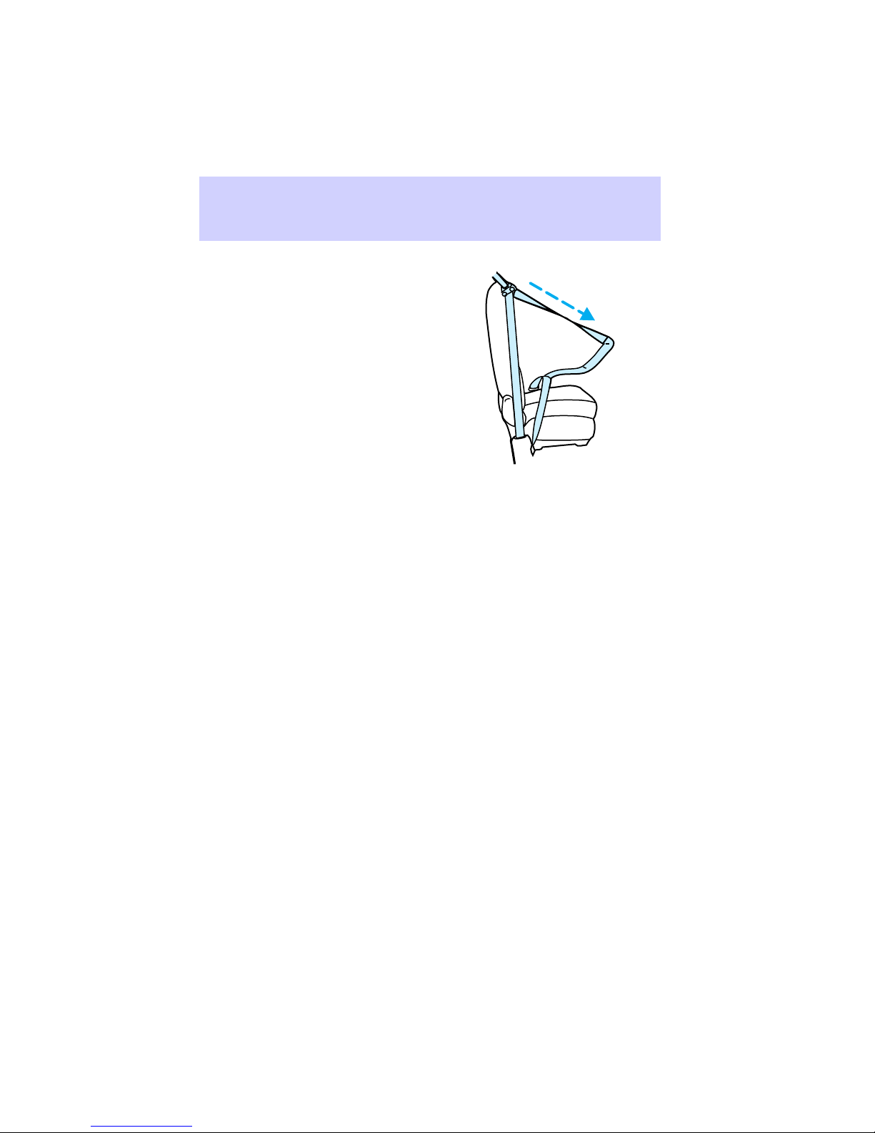
How to use the automatic
locking mode
1. Buckle the combination lap and
shoulder belt.
66
Page 67
Seating and safety restraints
2. Grasp the shoulder belt portion
and pull downward until the entire
belt is extracted.
3. Allow the belt to retract. As the
belt retracts, you will hear a
clicking sound. This indicates that
the safety belt is now in the
automatic locking mode.
How to cancel the automatic
locking mode
Disconnect the combination
lap/shoulder belt and allow it to
completely retract to cancel the
automatic locking mode and
activate the vehicle sensitive
(emergency) locking mode.
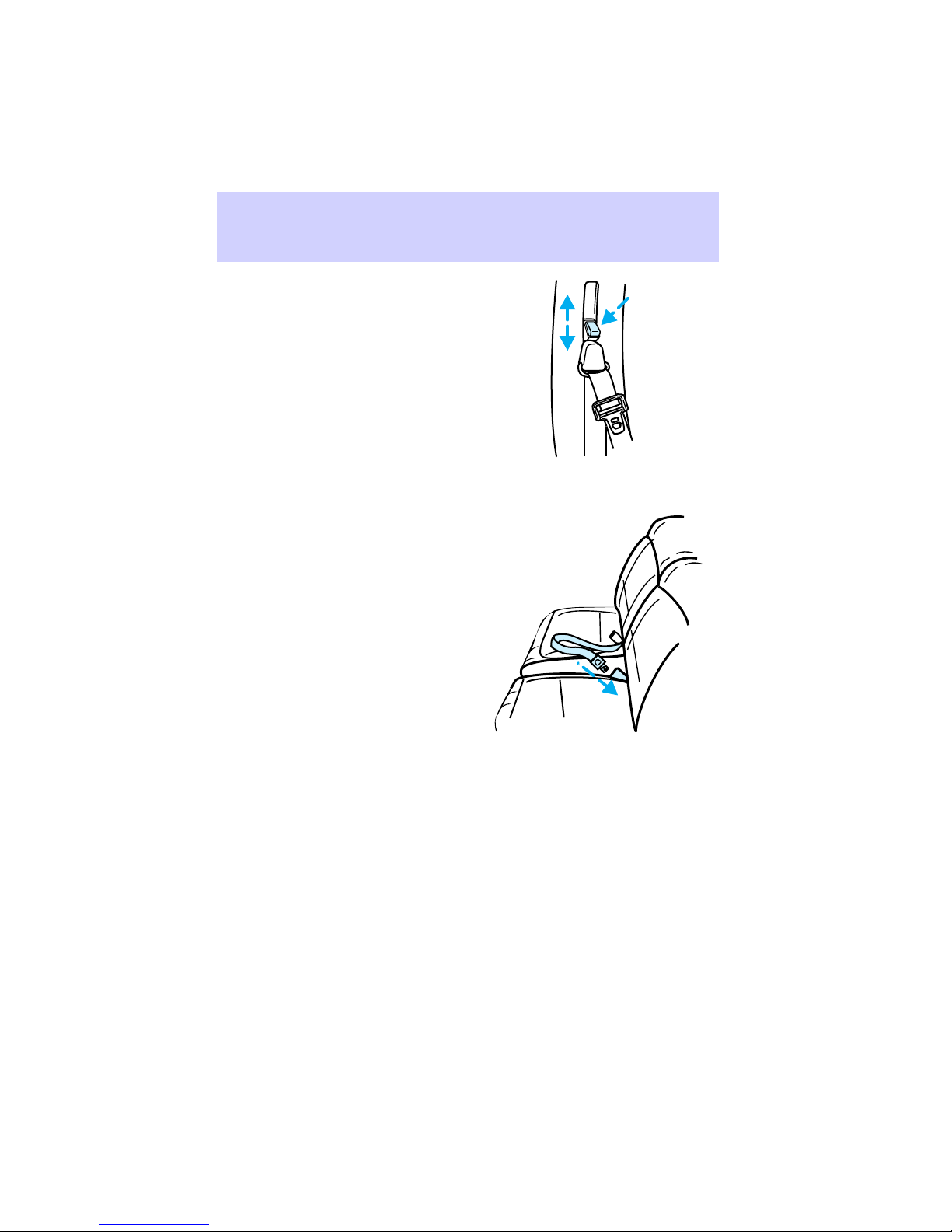
Front seat safety belt height
adjustment
Your vehicle has safety belt height
adjustments for the driver and
passenger seating positions.
Adjust the height of the shoulder
belt so the belt rests across the
middle of your shoulder.
67
Page 68
Seating and safety restraints
1. To lower shoulder belt height,
push the button and slide down.
2. To raise the height of the
shoulder belt, push the button and
slide up.
3. Pull down on the height
adjustment assembly to make sure
it is locked in place.
Center rear lap belt
The center rear seating position
has a lap belt with retractor.
To unfasten the safety belt:
1. Push the release button on the
buckle. This allows the tongue to
unlatch from the buckle.
2. While the belt retracts, guide
the tongue to its stowed position.
If you do not guide the tongue, it
may strike you or part of the
vehicle.
68
Page 69

Seating and safety restraints
SAFETY BELT WARNING AND
INDICATOR CHIME
The warning light illuminates
in the instrument cluster and a
chime sounds to remind the
occupants to fasten their safety
belts.
Conditions of operation
If... Then...
The safety belt is not buckled
before the ignition key is turned
to ON...
The safety belt is buckled while
the indicator light is illuminated
and the warning chime is
sounding...
The safety belt is buckled before
the ignition key is turned to ON...
SAFETY BELT MAINTENANCE
Check the safety belt systems
periodically to make sure that they
work properly and are not
damaged. Check the safety belts to
make sure there are no nicks,
wear, or cuts. If your vehicle has
been involved in an accident, have
all the safety belts and child seat
anchoring brackets (if equipped)
examined by a qualified technician.
The safety belt indicator light
illuminates for one to two minutes
and the warning chime sounds for
4-8 seconds.
The safety belt indicator light and
the warning chime turn off.
Both the safety belt warning light
and chime remain off.
69
Page 70

Seating and safety restraints
Energy absorbing sew pattern
The short plastic boot on the front
passenger safety belt covers an
energy absorbing sew pattern on
the safety belt. In the event of an
accident, the sew pattern may
release, and the orange REPLACE
BELT label may become visible. If
any part of the orange label is
exposed, the belt must be
replaced.
Failure to replace the
safety belt assembly under
the above conditions could result
in severe personal injuries in the
event of a collision.
BELT
REPLACE
Lincoln-Mercury recommends that
all safety belt assemblies used in
vehicles involved in a collision be
replaced. However, if the collision
was minor and a qualified
technician finds that the belts do
not show damage and continue to
operate properly, they do not need
to be replaced. Safety belt
assemblies not in use during a
collision should also be inspected
and replaced if either damage or
improper operation is noted.
70
Page 71

Seating and safety restraints
Safety belt extension assembly
For some people, the safety belt
may be too short even when it is
fully extended. You can add about
20 cm (8 in) to the belt length
with a safety belt extension
assembly (part # 611C22). Safety
belt extensions are available at no
cost from your dealer.
Use only extensions manufactured
by the same supplier as the safety
belt. Manufacturer identification is
located at the end of the webbing
on the label. Also, use the safety
belt extension only if the safety
belt is too short for you when fully
extended. Do not use extension to
change the fit of the shoulder belt
across the torso.
Failure to follow these
instructions will affect the
performance of the safety belts
and increase the risk of personal
injury.
Cleaning the safety belts
Clean the safety belts with a mild
soap solution recommended for
cleaning upholstery or carpets. Do
not bleach or dye the belts,
because these actions may weaken
the belt webbing.
AIR BAG PRECAUTIONS
Your vehicle is equipped with an
air bag supplemental restraint
system (SRS) designed to work
with safety belts to help protect
you and your right front seat
71
Page 72

Seating and safety restraints
passenger in the event of a
collision.
All occupants of the
vehicle, including the
driver, should always wear their
safety belts, even when an air
bag supplemental restraint
system is provided.
Do not place objects or
mount equipment on or
near the air bag cover on the
steering wheel or in front seat
areas that may come into contact
with a deploying air bag. Failure
to follow this instruction may
increase the risk of personal
injury in the event of a collision.
Do not attempt to service,
repair, or modify the air
bag supplemental restraint
system or its fuses. See your
Ford or Lincoln-Mercury dealer.
Rear-facing child seats or
infant carriers should
never be placed in the front seat.
Air bags and air bag equipped
vehicles should be disposed of only
by your dealer.
72
Page 73

Seating and safety restraints
AIR BAG DESCRIPTION
The air bag system activates in
collisions more severe than hitting
a parked vehicle of similar size and
weight head-on at about 45km/h
(28 mph).
The air bag system consists of two
parts:
• The driver air bag in the middle
of the steering wheel and the
passenger air bag near the glove
compartment.
• The electrical system, made up
of impact sensors, a diagnostic
module, and a backup power
supply.
The diagnostic module monitors its
own internal circuits and the
supplemental air bag electrical
system readiness (including the
impact sensors), the system wiring,
the air bag system readiness light,
the air bag back up power, and the
air bag ignitors.
The air bags inflate within a
fraction of a second after air bag
sensors detect a severe frontal
collision. Gas generators within the
air bags fill the air bags with a
non-toxic, non-flammable gas.
After the vehicle occupants have
contacted the air bags, the gas
empties through holes in the air
100
5
6
120
80
4
oooo
60
140
3
H
UNLEADED
40
FUEL ONLY
160
2
C
000000
20
180
1
0
0
200
km/h
F
RPMx1000
P RND21
E
OFF
E
OFF
ON
OFF
VOL – PUSH ON
CLK
ST
FM 1
AM
BALFADE
BASSTREB
FM
AUTO
PUSH
RSM
SET
ACC
COAST
SRS
SET
SEEK
TAPECD
EJ
SCAN
DOLBY SYSTEM
TUNE
DISCS
FF
SHUFFLE
REW
COMP
SIDE 1-2
2
5
6
1
4
3
OFF
LO
A/C
*
MAX
*
HI
A/C
73
Page 74

Seating and safety restraints
bags, and the air bags deflate. You
may notice smoke and smell the
escaping gas after the air bags
deflate. This is normal.
You and your passenger must wear
your safety belts in order for the
air bag system to operate
effectively.
AIR BAG WARNING LIGHT AND
CHIME
When you turn the ignition key to
the ON position, the
light in the instrument cluster
illuminates for approximately six
seconds to indicate the air bag
system is functional.
If you hear a group of five beeps,
or if the
not illuminate, stays lit, or flashes,
the air bag system requires
immediate service. Have the
vehicle serviced at your dealer.
CHILD RESTRAINT
PRECAUTIONS
You are required by law to use
safety restraints in the United
States and Canada. If small
children ride in your vehicle
(generally children who are four
years of age or younger and who
weigh 18 kg [40 lb or less]), you
must put them in safety seats
made especially for children.
Check your local and state laws for
specific requirements regarding the
safety of your children.
warning light does
warning
74
Page 75

Seating and safety restraints
Never let a passenger hold
a child on his or her lap
while the vehicle is moving. The
passenger cannot protect the
child from injury in a collision.
Always follow the instructions and
warnings that come with any infant
or child restraint you might use.
If possible, place children in the
rear seat of your vehicle. Accident
statistics suggest children are safer
when properly restrained in rear
seating positions than in the front
seating positions.
CHILDREN AND SAFETY BELTS
Children who are too large for
child safety seats (as specified by
the manufacturer of your child
safety seat) should always wear
their safety belts.
Follow all the important safety
restraint and air bag precautions
that apply to adult passengers in
your vehicle.
If the shoulder belt portion of a
combination lap and shoulder belt
can be positioned so it does not
cross or rest in front of the child’s
face or neck, the child should wear
the lap and shoulder belt. Moving
the child closer to the center of
the vehicle may help to provide a
good shoulder belt fit.
If the shoulder belt cannot be
properly positioned:
• Move the child to a seat with a
lap belt only.
75
Page 76

Seating and safety restraints
OR
• If the child is the proper size,
restrain the child in a safety
seat.
CHILDREN AND INFANT OR
CHILD SAFETY SEATS
Carefully follow all of the
manufacturer’s instructions
included with the safety seat you
put in your vehicle. If you do not
install and use the safety seat
properly, the child may be
injured in a sudden stop or
collision.
When installing a child safety seat:
• Use the correct safety belt
buckle for that seating position.
• Make sure the tongue is
securely fastened in the buckle.
• Keep the buckle release button
pointing up and away from the
safety seat, with the tongue
between the child seat and the
release button, to prevent
accidental unbuckling.
• Place seatbacks in the upright
position.
• Put the safety belt in the
automatic locking mode. Refer
to How to use the automatic
locking mode.
PRESS
76
Page 77

Seating and safety restraints
Installing child safety seats in
combination lap and shoulder
belt seating positions
1. Position the child safety seat in
a seat with a combination lap and
shoulder belt.
If you choose to install a child
safety seat in the front passenger
seat, move the seat as far back as
possible.
Rear-facing child seats or
infant carriers should
never be placed in the front seat.
2. Pull down on the shoulder belt
and then grasp the shoulder belt
and lap belt together.
77
Page 78

Seating and safety restraints
3. While holding the shoulder and
lap belt portions together, route
the tongue through the child seat
according to the child seat
manufacturer’s instructions. Be
sure the belt webbing is not
twisted.
4. Insert the belt tongue into the
proper buckle for that seating
position until you hear and feel the
latch engage. Make sure the
tongue is latched securely by
pulling on it.
5. Grasp the shoulder portion of
the belt and pull downward until
all of the belt is extracted and a
click is heard to put the retractor
in the automatic locking mode.
PRESS
6. Allow the belt to retract. The
belt will click as it retracts to
indicate it is in the automatic
locking mode.
78
Page 79

Seating and safety restraints
7. Pull the lap belt portion across
the child seat toward the buckle
and pull up on the shoulder belt
while pushing down on the child
seat.
8. Allow the safety belt to retract
to remove any slack in the belt.
9. Before placing a child in the
seat, forcibly tilt the seat forward
and back to make sure the seat is
securely held in place.
10. Try to pull belt out of the
retractor to make sure the
retractor is in the automatic
locking mode (you should not be
able to pull more belt out). If the
retractor is not locked, unbuckle
the belt and repeat Steps 2
through 9.
Check to make sure the child seat
is properly secured before each
use.
Using a tether strap
Ford recommends using child
safety seats with a top tether
79
Page 80

Seating and safety restraints
strap. Contact the manufacturer of
your safety seat for information
about ordering a tether strap if
one is not provided to you. Contact
your Ford dealer for a free tether
anchor kit (613D74) so you can
attach a tether anchor bracket to
the tether anchor attachment
locations in the rear floor.
Carefully follow the instructions
provided with the kit.
Only use the tether
attachment hole locations
shown. The tether anchor may
not perform properly if the
wrong mounting location is used.
Follow the child seat
manufacturer’s instructions for
installing a child seat with a tether
strap.
Ford recommends you attach
tethered safety seats in a rear
seating position with the tether
strap attached to the tether
anchoring bracket as shown in the
instructions provided with the
tether anchor kit.
If a tethered seat must be installed
in the front passenger seat:
1. Buckle the safety belt in the
seat directly behind the front
passenger seat.
2. Place the rear safety belt in the
automatic locking mode. Refer to
How to use the automatic locking
mode in this chapter.
3. Install the child safety seat in
the front seat. Refer to the
80
Page 81

Seating and safety restraints
instruction under Installing child
safety seats in combination lap
and shoulder belt seating
positions in this chapter.
4. Hook the tether strap around
the webbing near the center of the
shoulder portion of the rear safety
belt and tighten.
BUILT-IN CHILD SEAT (IF
EQUIPPED)
The rear seat may include a
built-in child seat. This child seat
conforms to all federal and
Canadian motor vehicle safety
standards. Read the labels located
on the child seat cushion and
shoulder belt for information on
the built-in child seat.
Use the built-in child seat only
under the following conditions:
Child’s Age Child’s Weight Child’s Height
At least 1 year 10-27 kg (22-60 lb) Shoulders must be
below the shoulder
harness slots on the
built-in child seat
Children not meeting these
requirements should be secured in
an approved aftermarket child
seat. Refer to Children and
infant or child safety seats in this
chapter.
81
Page 82

Seating and safety restraints
Placing your child in the built-in
child seat
Failure to follow all of the
instructions on the use of
this child restraint system can
result in your child striking the
vehicle’s interior during a sudden
stop or crash.
Never use the built-in
child seat as a booster
cushion with the adult safety
belts. A child using the adult
belts could slide forward and out
from under the safety belts.
The rear seatback must be
fully locked before
operating the child restraint
system.
1. Grasp the pull strap and pull
toward you approximately one
inch, then slide hand under head
restraint and slide upwards to full
position.
82
Page 83

2. Pull both Velcrot straps to
release child seat cushion.
3. Lower child seat cushion.
Seating and safety restraints
83
Page 84
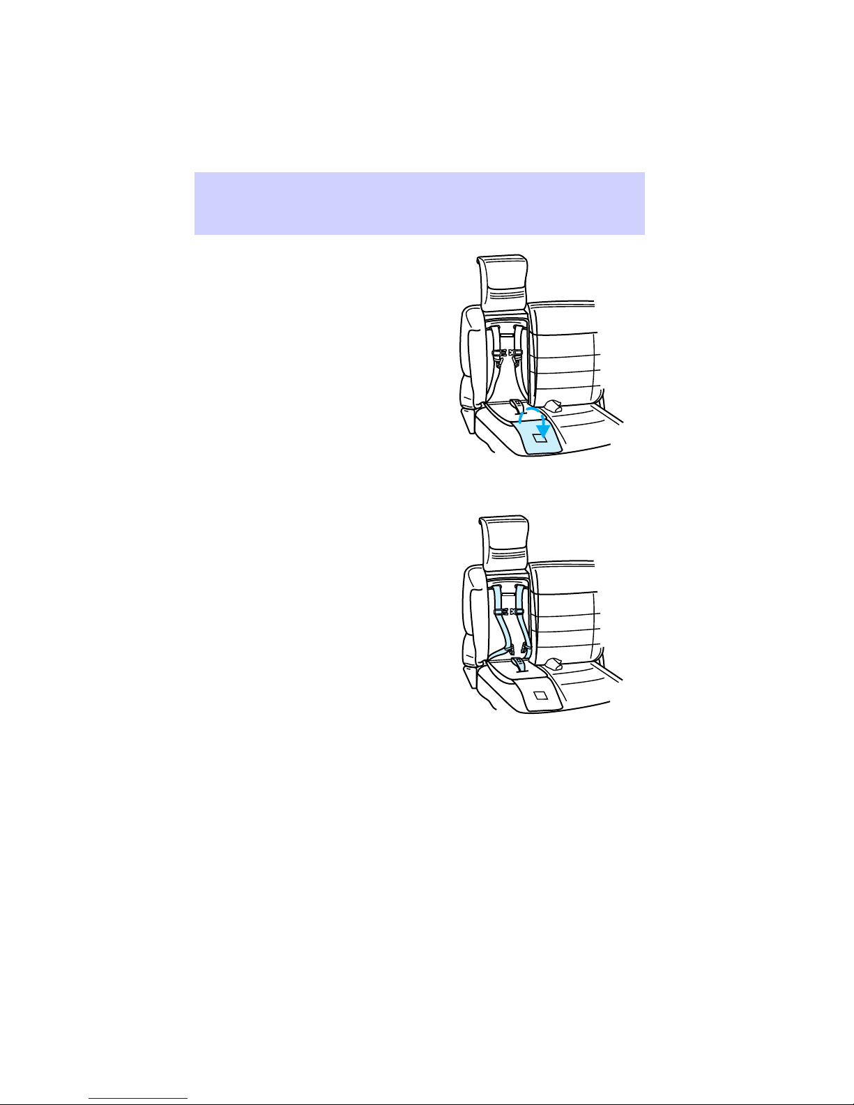
Seating and safety restraints
4. Unfold cushion protector flap
onto adult seat cushion.
5. If connected, disconnect the
chest clip and buckles.
6. Place the child in the seat and
position the left shoulder belt over
the child’s left shoulder first, then
place the right shoulder belt over
the child’s right shoulder.
84
Page 85

Seating and safety restraints
7. Insert the left and right safety
belt tongues into the left and right
slots of the crotch buckle. Verify
that the indicator window on each
tongue is green to ensure proper
safety belt connections.
If both tongues do not
latch in the buckle, do not
use the child seat. See your
dealer for repairs.
8. Fasten the left and right chest
clip halves together, and adjust the
clip (up or down) to comfortably
hold the shoulder belts in place on
the child’s chest.
The chest clip is designed to easily
pull apart in the event of an
accident. The clip helps keep the
belts on a squirming or sleeping
child.
85
Page 86

Seating and safety restraints
9. Pull on the safety belt tongues
to ensure they are both securely
latched. If they are not latched,
repeat Steps 7 and 8.
If necessary, the shoulder belts can
be put in automatic locking mode
(ALR) to limit the child’s
movement in the child seat. The
ALR mode may be used if the child
is sleeping or attempting to get out
of the child seat.
If not placed in the ALR mode, the
child seat shoulder belts are in a
vehicle sensitive (emergency
locking) mode, adjusting shoulder
belt tightness in response to
vehicle movement.
Activating the automatic locking
mode (ALR) on the built-in child
seat.
1. Pull out right shoulder belt fully.
2. Allow the belts to tighten snugly
against child’s shoulders.
Canceling the automatic locking
mode (ALR) on the built-in child
seat
1. Disconnect the chest clip and
remove the left and right safety
belt tongues from the crotch
buckle.
86
Page 87

Seating and safety restraints
2. Allow the shoulder belts to fully
retract.
Removing your child from the
built-in child seat
1. Disconnect the chest clip by
squeezing the release tabs together
and pulling the two sides apart.
2. Press the release button on the
crotch buckle.
3. Slide the shoulder belts off the
child’s shoulders and remove child.
If ALR is engaged, hold either left
or right shoulder belt fully out
while helping the child slide his
arms out of the belts.
4. Fold the cushion protector flap
onto the child seat cushion. Slide
the belt tongues up and out of the
way of the cushion, then return
the child seat cushion to the
stowed (upright) position.
5. Slide the Velcrot straps through
the D-rings on the child seat
cushion and attach.
6. Slide head restraint down until
the top of the head restraint is
flush with the top of the adult seat
back.
87
Page 88

Seating and safety restraints
7. Press firmly on the top center of
the built-in child seat head
restraint to ensure it is stowed
properly.
Inspecting the built-in child seat
after a collision
All built-in child restraints,
including seats, buckles,
retractors, seat latches,
interlocks, and attaching
hardware should be inspected by
a qualified dealer technician after
any collision. If the child seat
was in use during a collision,
Ford recommends replacing it.
However, if the collision was
minor and a qualified technician
finds that the child restraints do
not show damage and continue
to operate properly, they do not
need to be replaced. Built-in
child seats not in use during a
collision should also be inspected
and replaced if either damage or
improper operation is noted.
88
Page 89

IMPORTANT SAFETY
PRECAUTIONS
Extended idling at high
engine speeds can produce
very high temperatures in the
engine and exhaust system,
creating the risk of fire or other
damage.
Do not park, idle, or drive
your vehicle in dry grass
or other dry ground cover. The
emission system heats up the
engine compartment and exhaust
system, which can start a fire.
Do not start your vehicle
in a closed garage or other
enclosed area. Never sit in a
stopped vehicle for more than a
short period of time with the
engine running. Exhaust fumes
are toxic. See Guarding against
exhaust fumes later in this
chapter for more instructions.
Starting your vehicle
PREPARING TO START YOUR
VEHICLE
Before starting the vehicle:
1. Make sure all vehicle occupants
have buckled their safety belts.
Refer to the Seating and safety
restraints chapter for more
information.
89
Page 90
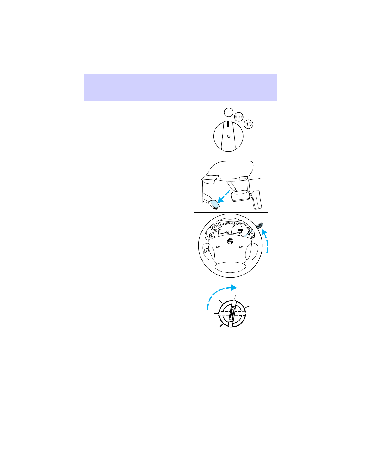
Starting your vehicle
2. Make sure the headlamps and
vehicle accessories are off.
3. Make sure the parking brake is
set and the gearshift lever is in P
(Park).
OFF
100
5
6
120
80
4
3
H
2
C
1
0
F
E
ON
OFF
UNLEADED
FUEL ONLY
RPMx1000
P RND21
SRS
60
40
20
0
MPH km/h
oooo
000000
140
H
160
L
180
200
H
- +
L
RSM
SET
ACC
COAST
4. Turn the key to the ON position
(without turning the key to
START).
90
OFF
ON
START
LOCK
ACCESSORY
Page 91
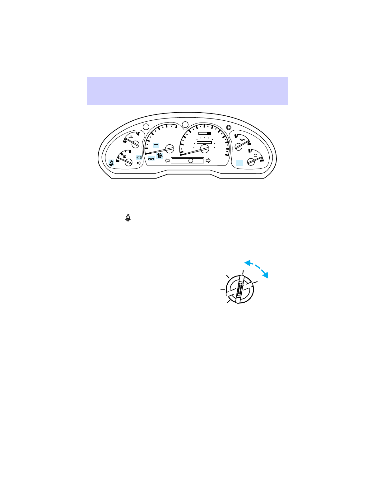
CHECK
GAGE
H
C
DOOR
AJAR
F
E
ABS
1
0
BRAKE
! P
5
6
4
3
UNLEADED
FUEL ONLY
2
- +
RPMx 1000
P RND21
The above lights illuminate briefly.
If a light fails to illuminate, have
the vehicle serviced.
If the driver’s safety belt is
fastened, the
light does not
illuminate.
STARTING THE VEHICLE
After completing the steps under
Preparing to start the vehicle:
1. Turn the key to START, hold
until engine is running, then
release. DO NOT press the
accelerator.
The key will return to the ON
position.
2. After idling for a few seconds,
apply the brake and release the
parking brake.
Starting your vehicle
60
70
50
oooo
40
60
30
40
20
20
10
0
MPH km/h
100
80
120
000000
LOCK
80
140
90
160
100
180
110
120
ANTI-
THEFT
OFF
ACCESSORY
H
CHECK
ENGINE
ON
SPEED
L
CONT
H
- +
L
O/D
OFF
START
Special conditions when
starting
Starting a cold engine
At temperatures -12°C (10°F) and
below, do not hold the key in the
START position longer than 15
91
Page 92

Starting your vehicle
seconds. If the engine does not
start on the first attempt:
1. Turn the ignition key to LOCK
and wait approximately 10
seconds.
2. Try starting the engine again.
At temperatures above -12°C
(10°F), do not hold the key in the
START position longer than five
seconds. If the engine does not
start on the first attempt:
1. Turn the ignition key to LOCK
and wait approximately five
seconds.
2. Try starting the engine again.
Starting a warm engine
Do not hold the key in the START
position for longer than five
seconds. If the engine does not
start on the first attempt:
1. Turn the ignition key to LOCK
and wait a few seconds until the
starter stops.
2. Try starting the engine again.
Starting the engine after two
failed attempts (warm or cold)
If the engine does not start after
two attempts:
1. Turn the key to LOCK and wait
about two minutes.
92
Page 93

2. Press the accelerator all the way
to the floor and hold.
3. Turn the key to START. Release
it once the engine starts.
4. Release the accelerator
gradually as the engine speeds up.
If the engine still does not start,
refer to Fuel pump shutoff
switch in the Roadside
emergencies chapter.
Engine block heater (if
equipped)
To prevent electrical
shock, do not use your
engine block heater with
ungrounded electrical systems or
two-pronged (cheater) adapters.
Starting your vehicle
Engine block heaters are strongly
recommended if you live in a
region where temperatures reach
-23°C (-10°F) or below. An engine
block heater works by warming the
engine coolant. This improves
engine starting by warming the
engine faster. Engine block heater
operation also allows the heater
and defrost system to respond
more quickly than usual.
93
Page 94

Starting your vehicle
GUARDING AGAINST EXHAUST
FUMES
Carbon monoxide, although
colorless and odorless, is present
in exhaust fumes. Take precautions
to avoid its dangerous effects.
If you smell exhaust fumes
inside your vehicle, have
your dealer inspect your vehicle
immediately. Do not drive if you
smell exhaust fumes.
Have the exhaust and body
ventilation system checked
whenever:
• The vehicle is raised for service.
• The sound of the exhaust
system changes.
• The vehicle has been damaged
in a collision.
94
Page 95

Ventilating your vehicle
• If the engine is idling while the
vehicle is stopped in an open
area for long periods of time,
open the windows at least 2.5
cm (1 inch). Adjust the heating
or air conditioning to bring in
fresh air.
• Improve vehicle ventilation by
keeping all air inlet vents clear
of snow, leaves and other debris.
Starting your vehicle
DOOR LOCK
U
L
AUTO
OFF
A/C
MAX
A/C
95
Page 96

Driving
BRAKES
The anti-lock brake system
(ABS)
Anti-lock brake operation differs
slightly from standard brake
operation.
Apply the brakes steadily. DO NOT
pump the brakes in a panic stop.
The brake system will prevent
wheel lockup by automatically
releasing and reapplying the
brakes.
Even with ABS, the brakes could
lock up on roads with alternating
slippery and dry patches or with
loose surfaces such as snow or
gravel. Be careful when braking.
The ABS conducts a self-test each
time the vehicle is driven. A
mechanical noise may be heard
while the system conducts its
self-test.
Occasional brake squeal during
light to moderate stops is normal.
Significantly increased squeal is an
indicator that brake service is
needed.
After driving through standing
water, gently apply the brakes
several times to dry them.
If driving down a long or steep hill,
shift to a lower gear and do not
apply the brakes continuously.
Continuously applying the brakes
on a hill could overheat them and
make them less effective.
96
Page 97
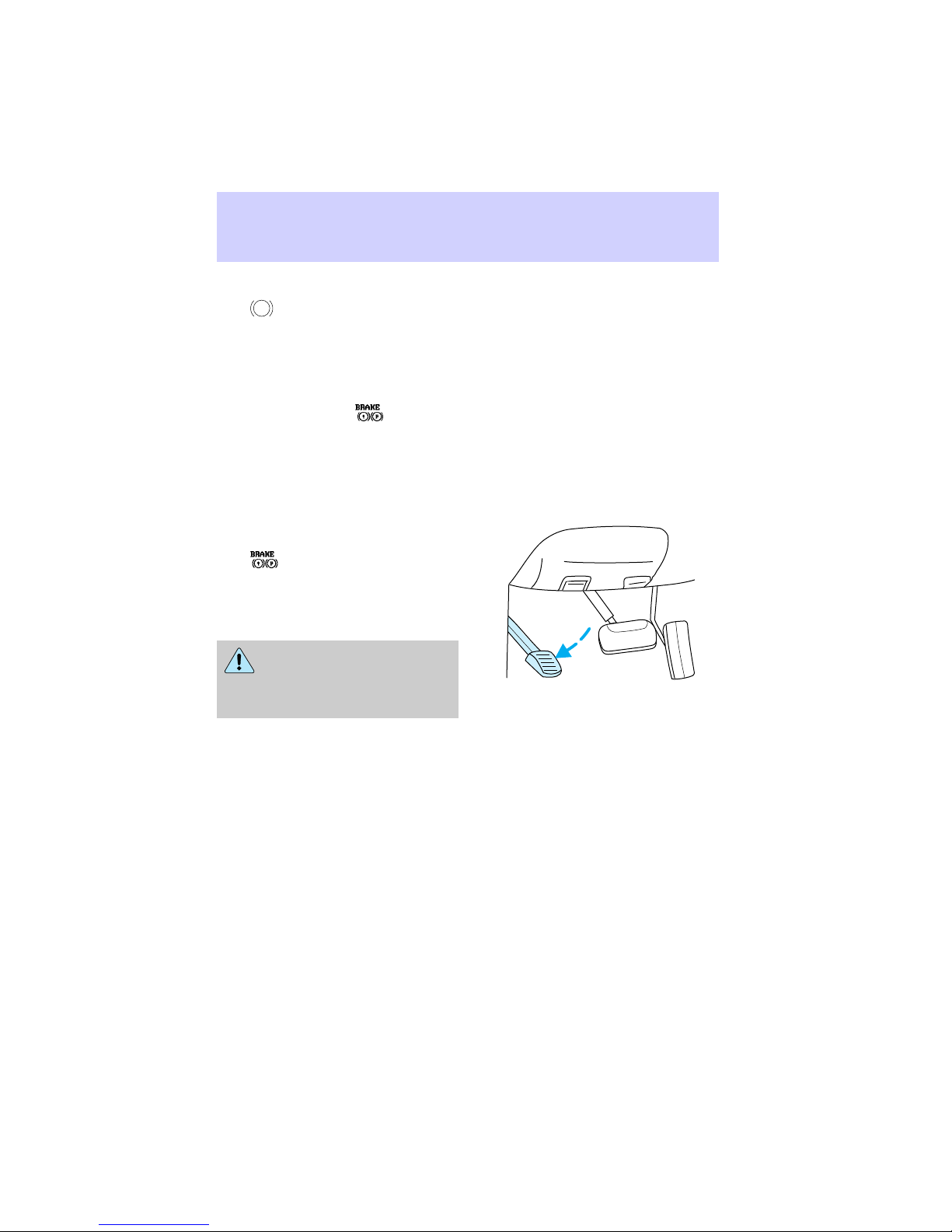
ABS warning light
ABS
The
light in the instrument
cluster illuminates and remains
illuminated if an ABS fault is
detected. Have your vehicle
serviced as soon as possible.
Normal braking operation is still
effective unless the
light is
also illuminated.
Parking brake
The parking brake should be used
whenever the vehicle is parked.
Push pedal downward to set the
parking brake.
The
light in the instrument
cluster illuminates and remains
illuminated (when the ignition is
turned to ON) until the parking
brake is released.
Always set the parking
brake fully and make sure
that the gearshift is securely
latched in P (Park).
Driving
The parking brake is not designed
to stop a moving vehicle. However,
if the normal brakes fail, the
parking brake can be used to stop
your vehicle in an emergency.
Since the parking brake applies
only the rear brakes, the vehicle’s
stopping distance will increase
greatly and the handling of your
vehicle will be adversely affected.
97
Page 98

Driving
Pull release handle towards you to
release parking brake.
If the parking brake is fully
released, but the
warning light remains on,
have the brakes checked
immediately. They may not be
working properly.
AUTOMATIC TRANSMISSION
OPERATION (4R70W)
Hold the brake pedal down
while you move the
gearshift from position to
position. If you do not hold the
brake pedal down, your vehicle
may move unexpectedly and
injure someone.
98
Page 99

Pull gearshift lever towards you
and downward to move the
automatic gearshift.
P - Park Always come to a
complete stop before shifting into
or out of P (Park).
Always set the parking
brake fully and make sure
that the gearshift is securely
latched in P (Park).
R - Reverse Always come to a
complete stop before shifting into
or out of R (Reverse).
N - Neutral Vehicle is free to roll.
Driving
P RND21
P RND21
Do not leave the vehicle
unattended with the
transfer case in the N (Neutral)
position. Always set the parking
brake fully and turn off the
ignition when leaving the vehicle.
99
Page 100

Driving
D
- Overdrive The normal
driving position for the best fuel
economy. Transmission operates in
gears 1-4.
disengaged by pressing the
transmission control switch on the
gearshift lever. The transmission
control indicator light on
instrument cluster will remain off.
D - Drive Not shown on the
display. Activate by pressing
transmission control switch.
O/D
OFF
instrument cluster. Transmission
operates in gears 1-3. Provides
more engine braking than
D
(Overdrive) and is useful when
towing a trailer or heavy loads
through hilly areas.
To return to normal overdrive
mode, press the transmission
control switch again.
off.
When starting your vehicle, the
transmission will automatically
return to normal
mode.
2 - Second Use 2 (Second) to
start-up on slippery roads or to
provide additional engine braking
D
(Overdrive) can be
will illuminate on the
O/D
OFF
D
(Overdrive)
will turn
5
6
60
70
50
4
oooo
40
80
100
3
80
UNLEADED
FUEL ONLY
RPMx1000
P RND21
SRS
120
140
60
30
H
90
40
160
000000
L
100
20
180
20
110
10
0
120
km/h
H
- +
L
RSM
SET
ACC
COAST
O/D
ON/OFF
H
2
C
1
0
F
E
ON
OFF
100
 Loading...