

Page 1

Service Manual Outline
Section 1 - Important Information
A - Specifications
B - Maintenance
C - General Information
D - Outboard Installation
Section 2 - Electrical
A - Ignition
B - Charging & Starting System
C - Timing, Synchronizing & Adjusting
D - Wiring Diagrams
Section 3 - Fuel System
A - Carburetor/Fuel Pump
B - Emissions
Section 4 - Powerhead
Section 5 - Mid-Section
Section 6 - Lower Unit
A - Gear Housing
B - Jet Drive
Section 7 - Attachments/Control Linkage
A - Throttle/Shift Linkage
B - Tiller Handle
C - Side Shift
Section 8 - Manual Starter
Important Information
1
Electrical
2
Fuel System
3
Powerhead
4
Mid-Section
5
Lower Unit
6
Attachment/Control Linkage
7
Manual Starter
8
9
90-826883R2 JUNE 1998 Page iii
Page 2
Notice
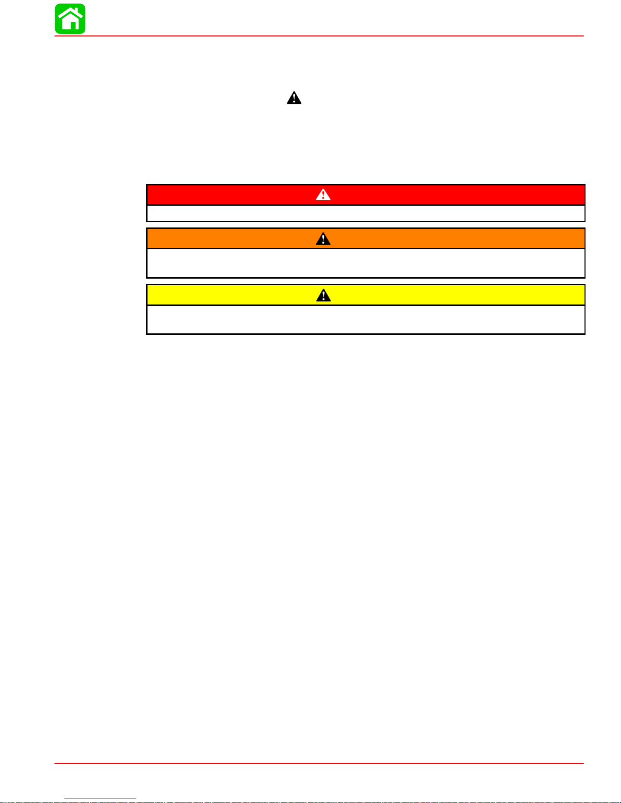
Throughout this publication, “Dangers”, “Warnings” and “Cautions” (accompanied by the International HAZARD Symbol
cerning a particular service or operation that may be hazardous if performed incorrectly or
carelessly . OBSERVE THEM CAREFULLY!
These “Safety Alerts” alone cannot eliminate the hazards that they signal. Strict compliance
to these special instructions when performing the service, plus “Common Sense” operation,
are major accident prevention measures.
) are used to alert the mechanic to special instructions con-
DANGER
DANGER - Immediate hazards which WILL result in severe personal injury or death.
W ARNING
WARNING - Hazards or unsafe practices which COULD result in severe personal injury or death.
CAUTION
Hazards or unsafe practices which could result in minor personal injury or product
or property damage.
Notice to Users of This Manual
This service manual has been written and published by the Service Department of Mercury
Marine to aid our dealers’ mechanics and company service personnel when servicing the
products described herein.
It is assumed that these personnel are familiar with the servicing procedures of these products, or like or similar products manufactured and marketed by Mercury Marine, that they
have been trained in the recommended servicing procedures of these products which includes the use of mechanics’ common hand tools and the special Mercury Marine or recommended tools from other suppliers.
We could not possibly know of and advise the service trade of all conceivable procedures
by which a service might be performed and of the possible hazards and/or results of each
method. We have not undertaken any such wide evaluation. Therefore, anyone who uses
a service procedure and/or tool, which is not recommended by the manufacturer, first must
completely satisfy himself that neither his nor the products safety will be endangered by the
service procedure selected.
All information, illustrations and specifications contained in this manual are based on the
latest product information available at the time of publication. As required, revisions to this
manual will be sent to all dealers contracted by us to sell and/or service these products.
It should be kept in mind, while working on the product, that the electrical system and ignition
system are capable of violent and damaging short circuits or severe electrical shocks. When
performing any work where electrical terminals could possibly be grounded or touched by
the mechanic, the battery cables should be disconnected at the battery.
Any time the intake or exhaust openings are exposed during service they should be covered
to protect against accidental entrance of foreign material which could enter the cylinders and
cause extensive internal damage when the engine is started.
90-826883R2 JUNE 1998 Page i
Page 3
It is important to note, during any maintenance procedure replacement fasteners must have
the same measurements and strength as those removed. Numbers on the heads of the metric bolts and on the surfaces of metric nuts indicate their strength. American bolts use radial
lines for this purpose, while most American nuts do not have strength markings. Mismatched or incorrect fasteners can result in damage or malfunction, or possibly personal
injury . Therefore, fasteners removed should be saved for reuse in the same locations whenever possible. Where the fasteners are not satisfactory for re-use, care should be taken to
select a replacement that matches the original.
Cleanliness and Care of Outboard Motor
A marine power product is a combination of many machined, honed, polished and lapped
surfaces with tolerances that are measured in the ten thousands of an inch/mm. When any
product component is serviced, care and cleanliness are important. Throughout this manual, it should be understood that proper cleaning, and protection of machined surfaces and
friction areas is a part of the repair procedure. This is considered standard shop practice
even if not specifically stated.
Whenever components are removed for service, they should be retained in order. At the
time of installation, they should be installed in the same locations and with the same mating
surfaces as when removed.
Personnel should not work on or under an outboard which is suspended. Outboards should
be attached to work stands, or lowered to ground as soon as possible.
We reserve the right to make changes to this manual without prior notification.
Refer to dealer service bulletins for other pertinent information concerning the products de-
scribed in this manual.
Page Numbering
Two number groups appear at the bottom of each page. The example below is self-explanatory .
90-826883 R2 JUNE 1998
EXAMPLE:
6A-7
Revision No. 2
Month of Printing
Year of Printing
Page ii 90-826883R2 JUNE 1998
Section Number
Part of Section Letter
Page Number
Page 4

SPECIFICATIONS
IMPORTANT INFORMATION
Section 1A - Specifications
Table of Contents
Master Specifications 1A-2. . . . . . . . . . . . . . . . . . . . . . . . .
1
A
90-826883R2 JUNE 1998 Page 1A-1
Page 5
SPECIFICATIONS
Master Specifications
Model 15XD/20 Jet /20/25
HORSEPOWER
(KW)
OUTBOARD
WEIGHT
CYLINDER
BLOCK
Model 20 Jet
Model 20
Model 25
15 in. (38 cm)
20 in. (51 cm)
20 Jet
Type
Displacement
20 (14.9)
20 (14.9
25 (18.7)
114 lbs - 52 kg
117 lbs - 53 kg
124 lbs - 56 kg
Two Cylinder - Two Cycle
24.4 cu. in. (400 cc)
STROKE Length 2.362 in. (60 mm)
CYLINDER
BORE
Diameter (Standard)
Taper/Out of Round Maximum*
2.562 in. (65.01 mm)
0.003 in. (0.08 mm)*
Bore Type:
S/N 0G202749 and Below
S/N 0G202750 and Above
CRANK SHAFT Top Main Bearing Journal
Center Main Bearing Journal
Bottom Main Bearing Journal
Connecting Rod Journal
End Play
CONNECTING
ROD
Piston Pin End (I.D.)
Crankpin End (I.D.)
1.251 in. (31.77 mm)
1.000 in. (25.40 mm)
1.125 in. (28.58 mm)
0.883 in. (22.43 mm)
0.004-0.019 (0.10-0.64 mm)
0.897 in. (22.78 mm)
1.196 in. (30.38 mm)
Chrome
Mercosil
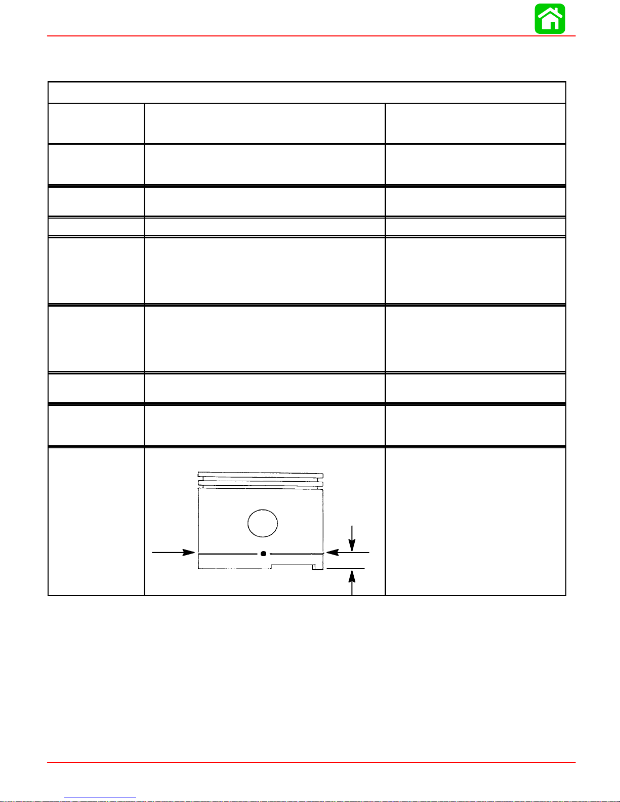
PISTON Piston Type
O.D. at Skirt (Standard)
Ring End Gap
PISTON DIA.
Dimension “A”
at Right Angle
°) to Pis-
(90
ton Pin
*Models S/N 0G202749 and Below:
NOTE: The cylinder bores are chrome and cannot be be rebored or efficiently honed.
Check each cylinder bore for an out-of-round “egg shaped” cylinder. A maximum of 0.003
in. (0076mm) is allowable.
*Models S/N 0G202750 and Above:
NOTE: The cylinder block is Mercosil and the cylinders can be rebored to 0.030 in. over-
sized. Check each cylinder bore for an out-of-round “egg shaped” cylinder. A maximum
of 0.003 in. (0.076mm) is allowed.
0.50 in.
(12.7 mm)
Aluminum
2.5583 - 2.5593 (64.98 - 65.00)
0.011-0.025 (.28 mm - .64 mm)
2.5583 in. ± .0005 in.
(64.98 mm ± .0127 mm)
micrometer , measure dimension
“A” at location shown. Dimension
“A” should be 2.5583 in. ± .0005 for
a STANDARD size piston (new) Dimension “A” will be 0.001 – 0.0015
less if coating is worn off piston
(used)
Using a
Page 1A-2 90-826883R2 JUNE 1998
Page 6

Master Specifications
SPECIFICATIONS
GEAR
HOUSING
Forward - Neutral - Reverse
Gear Ratio
Gearcase Capacity
Lubricant Type
Full Shift
2.25:1
8.8 fl.oz. (260 ml)
Quicksilver Gear Lube Premium
Blend
Forward Gear - No. of Teeth-Type
Pinion Gear - No. of Teeth-Type
Pinion
Foreword Gear Backlash
Reverse Gear Backlash
Water Pressure @ RPM
Water Pressure With 120° Thermostat
2-7 PSI @ 2000 RPM
27
12
Not Adjustable
Not Adjustable
Not Adjustable
0-6 PSI (SPORADIC) 2000 RPM
MID
SECTION
FUEL
SYSTEM
Transom Height - Short Shaft
- Long Shaft
Fuel Pump Type
Recommended Gasoline
15 in. (38 cm)
20 in. (51 cm)
Integral
Automotive Unleaded
with a Minimum Pump Posted
Octane Rating of 87
Fuel Tank Capacity
Operating Fuel/Oil Ratio
6.6 U.S. Gallons
50:1
OIL Recommended Oil (Pre-Mix @ 50:1) NMMA TC-W II or TC-W III
2-Cycle Outboard Oil
STARTING
SYSTEM
CHARGING
SYSTEM
Manual Start
Rope Length
Electric Start
Ampere Draw (cranking)
Alternator Output
BLACK Stator - 2 Magnet Flywheel
RED Stator - 4 Magnet Flywheel
(8 Pole)(4 Pulses)
(10 Pole)(5 Pulses)
Recoil
66 in. (1676 mm)
12 Volt
55 amperes
4 Amp. (48 Watt)
@ 6000 RPM
6 amp (72 Watt)
@ 6000 RPM
BATTERY Battery Rating 465 Marine Cranking Amps (MCA)
or 350 Cold Cranking Amps (CCA)
90-826883R2 JUNE 1998 Page 1A-3
Page 7

SPECIFICATIONS
IGNITION
SYSTEM
Readings taken @
68°F (20°C).
Type
Spark Plug Type (NGK)
Spark Plug Gap
Spark Plug Hex
Firing Order
20 Jet 1994
20/25 1994
1
/2 THRU 1998
1
/2 THRU 1996
Electronic Spark Advance
Idle @ 750 ± 50 RPM (In Forward
Gear)
Fast Idle Speed
Maximum BTDC (Running)
Setup Timing
Stator High Speed Winding
Stator Low Speed Winding
Diode Test
Ignition Coil Resistance:
Primary
Secondary (w/o Boots)
20 Jet 1999 and Newer
20/25 1997/98 Models
Mechanical Spark Advance
Idle @ 750 ± 50 RPM (In Forward
Gear)
Fast Idle Speed
Maximum BTDC (Running)
Stator High Speed Winding
Stator Low Speed Winding
Diode Test
Ignition Coil Resistance:
Primary
Secondary (w/o Boots)
Trigger
Capacitor Discharge Ignition
NGK BP8H-N-10
0.040 in. (1.0 mm)
18 mm
1-2
4°±2° B.T.D.C (Not Adjustable)
1400 RPM ± 250 RPM
25°±1 @5500 RPM
28° B.T.D.C. @ 3000 ± 200 R.P.M.
(Set-up timing of 28° B.T.D.C. will
be retarded to 25° B.T.D.C. @
5500 R.P.M.)
100 – 180 Ω (RED – BLK)
2900 – 3500 Ω (BLUE – BLACK)
2800 – 3400 Ω (RED – BLUE)
0 Ω
850 – 1200 Ω
6°±1° B.T.D.C
1500 RPM ± 200 RPM
25°±1 @5500 RPM
120 - 180 Ω (BLK/WHT - GRD)
3200 - 3800 Ω (BLK/YEL - GRD)
3100 – 3700 Ω (BLK/YEL - BLK/
WHT)
0.02 - 0.04 Ω
8000 - 11000 Ω
6500 - 8500 Ω
JET DRIVE Impeller Liner Clearance 0.030 in. (0.8 mm)
* Use NGK BPZ8H-N-10 Where Radio Frequency Interference (RFI) Suppression is
Required.
Page 1A-4 90-826883R2 JUNE 1998
Page 8

Master Specifications
SPECIFICATIONS
CARBURETOR
SPECIFI-
CATIONS
TIMING
SPECIFI-
CATIONS
Idle RPM (In Forward Gear)
Wide Open Throttle (WOT) RPM
20
25
Idle Mixture Screw
Adjustment (Preset-Turns Out)
20
20 Jet
25/25 Seapro/25 Marathon
Float Level
Main Jet Size
1
1994
/2 thru 1996
-20 (WMC-44)
-25/20 Jet (WMC-45)
-25 Seapro/Marathon (WMC-46)
-25 Seapro/Marathon (WMC-46A)
1997 and Newer
-20 Jet (WMC-45)
-20 (WMC-52)
-25 (WMC-53)
-25 Seapro/Marathon (WMC-54)
20 Jet 19941/2 THRU 1998
1
20/25 1994
/2 THRU 1996
Electronic Spark Advance
Idle @ 750 ± 50 RPM (In Forward
Gear)
Fast Idle Speed
Maximum BTDC (Running)
Setup Timing
20/25 1997 AND NEWER
20 Jet 1999 AND NEWER
Mechanical Spark Advance
Idle @ 750 ± 50 RPM (In Forward
Gear)
Fast Idle Speed
Maximum BTDC (Running)
750 ± 50
4500 - 5500
5000 - 6000
1 ± 1/4 Turn
1-1/2 ± 1/2 Turn
1-1/4 ± 1/4 Turn
1.0 in. (25.4 mm)
0.044 in. (1.12 mm)
0.076 in. (1.93 mm)
0.076 in. (1.93 mm)
0.080 in. (2.03 mm)
0.076 in. (1.93 mm)
0.044 in. (1.12 mm)
0.076 in. (1.93 mm)
0.080 in. (2.03 mm)
4°±2° B.T.D.C (Not Adjustable)
1400 RPM ± 250 RPM
25°±1 @5500 RPM
28° B.T.D.C. @ 3000 ± 200 R.P.M.
(Set-up timing of 28° B.T.D.C. will
be retarded to 25° B.T.D.C. @
5500 R.P.M.)
6°±1° B.T.D.C
1500 RPM ± 200 RPM
25°±1 @5500 RPM
90-826883R2 JUNE 1998 Page 1A-5
Page 9
MAINTENANCE
IMPORTANT INFORMATION
Section 1B - Maintenance
Table of Contents
Table of Contents 1B-1. .. . . . . . . . . . . . . . . . . . . . . . . . . .
Specifications 1B-1. . . . . . . . . . . . . . . . . . . . . . . . . . . . . . .
Gear Case Lubricant Capacity 1B-1. . . . . . . . . . . . . .
Special Tools 1B-1. . . . . . . . . . . . . . . . . . . . . . . . . . . . .
Quicksilver Lubricant/Sealant 1B-2. . . . . . . . . . . . . . .
Inspection and Maintenance Schedule 1B-3. . . . . . . . . .
Before Each Use 1B-3. . . . . . . . . . . . . . . . . . . . . . . . .
After Each Use 1B-3. . . . . . . . . . . . . . . . . . . . . . . . . . .
Every 100 Hours of Use or O nce Yearly,
Whichever Occurs First 1B-3. . . . . . . . . . . . . . . . . . . .
Every 300 Hours of Use or T hree Years 1B-3. . . . . .
Flushing The Cooling System 1B-4. . . . . . . . . . . . . . . . .
Fuel System 1B-5. . . . . . . . . . . . . . . . . . . . . . . . . . . . . . . .
Fuel Line Inspection 1B-5. . . . . . . . . . . . . . . . . . . . . . .
Engine Fuel Filter 1B-5. . . . . . . . . . . . . . . . . . . . . . . . .
Corrosion Control Anode 1B-6. . . . . . . . . . . . . . . . . . . . .
Spark Plug Inspection 1B-7. . . . . . . . . . . . . . . . . . . . . . . .
1
B
Battery Inspection 1B-7. . . . . . . . . . . . . . . . . . . . . . . . . . .
Fuse Replacement -- Electric Start Remote
Control Models 1B-8. . . . . . . . . . . . . . . . . . . . . . . . . . . . . .
Lubrication Points 1B-8.. .. .. .. .. .. .. .. .. .. .. .. .. .
Gear Case Lubrication 1B-10. . . . . . . . . . . . . . . . . . . . . .
Gear Case Lubricant Capacity 1B-10. . . . . . . . . . . . .
Draining Gear Case 1B-10. . . . . . . . . . . . . . . . . . . . . .
Draining Gear Case 1B-1 1.. . . . . . . . . . . . . . . . . . . . .
Checking Lubricant Level and Refilling
Gear Case 1B-11. .. .. .. .. .. .. .. .. .. .. .. .. .. .. .
Storage Preparations 1B-12. . . . . . . . . . . . . . . . . . . . . . .
Fuel System 1B-12. . . . . . . . . . . . . . . . . . . . . . . . . . . .
Protecting External Engine Components 1B-12. . . .
Protecting Internal Engine Components 1B-12. . . . .
Gear Case 1B-13. . . . . . . . . . . . . . . . . . . . . . . . . . . . . .
Positioning Outboard for Storage 1B-13. . . . . . . . . .
Battery Storage 1B-13. . . . . . . . . . . . . . . . . . . . . . . . .
Specifications
Gear Case Lubricant Capacity
Gear Case Ratio Capacity
2.25:1 8.8 fl. oz. (260.0ml)
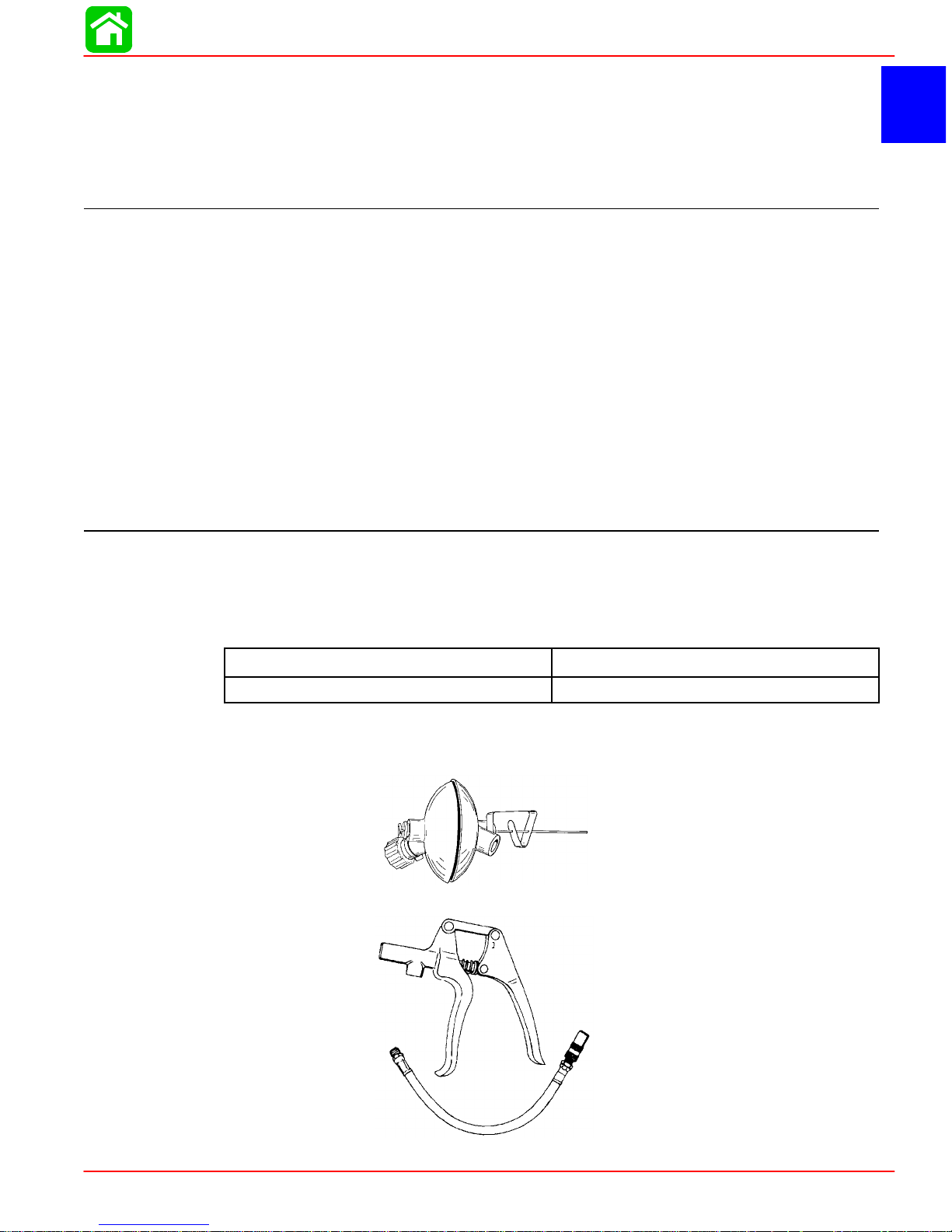
Special Tools
1. Flushing Attachment 44357A2
2. Grease Gun 91-37299A1
90-826883R2 JUNE 1998 Page 1B-1
Page 10
MAINTENANCE
Quicksilver Lubricant/Sealant
1. Quicksilver Anti-Corrosion Grease P/N 92-78376A6
2. 2-4-C Marine Lubricant with Teflon P/N 92-825407A12
3. SAE 30W Motor Oil P/N 92-97959
4. Quicksilver Gear Lubricant P/N 92-19007A24
Page 1B-2 90-826883R2 JUNE 1998
Page 11

Inspection and Maintenance Schedule
Before Each Use
1. Check that lanyard stop switch stops the engine.
2. Visually inspect the fuel system for deterioration or leaks.
3. Check outboard for tightness on transom.
4. Check steering system for binding or loose components.
5. Visually check steering link rod fasteners for proper tightness.
6. Check propeller blades for damage.
After Each Use
1. Flush out the outboard cooling system if operating in salt or polluted water.
2. Wash off all salt deposits and flush out the exhaust outlet of the propeller and gear
case with fresh water if operating in salt water.
Every 100 Hours of Use or Once Yearly, Whichever Occurs First
1. Lubricate all lubrication points. Lubricate more frequently when used in salt water.
MAINTENANCE
2. Inspect and clean spark plugs.
3. Check fuel line filter for contaminants.
4. Check carburetor adjustments, if required.
5. Check corrosion control anodes. Check more frequently when used in salt water.
6. Drain and replace gear case lubricant.
7. Lubricate splines on the drive shaft.*
8. Electric start models -- Inspect battery.
9. Remote control models -- Check control cable adjustments. *
10. Remove engine deposits with Quicksilver Power Tune Engine Cleaner.
11. Check tightness of bolts, nuts, and other fasteners.
12. Clean fuel tank pick up filter.
Every 300 Hours of Use or Three Years
1. Replace water pump impeller (more often if overheating occurs or reduced water
pressure is noted).*
*These items should be serviced by an authorized dealer.
90-826883R2 JUNE 1998 Page 1B-3
Page 12
MAINTENANCE
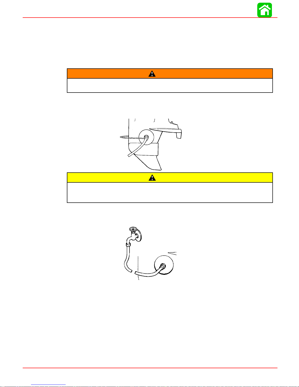
Flushing The Cooling System
Flush theinternal waterpassages of theoutboard with freshwater after eachuse in salt,
polluted, or muddy water. This will help prevent a buildup of deposits from clogging the
internal water passages.
Use a Quicksilver accessory (or equivalent) flushing attachment.
To avoid possible injury when flushing, remove the propeller.Refer to Propeller
Replacement.
1. Removepropeller(referto PropellerReplacement).Installtheflushing attachmentso
the rubber cups fit tightly over the cooling water intake holes.
WARNING
CAUTION
Never start or run your outboard (even momentarily) without water circulating
through the cooling water intake inthe gearcase toprevent damage to the water
pump (running dry) or overheating of the engine.
2. Attacha waterhose to theflushing attachment.Turnon the waterand adjustthe flow
sowaterisleaking aroundtherubbercupstoensurethe enginereceivesanadequate
supply of cooling water.
3. Start the engine and run it at idle speed in neutral shift position.
Page 1B-4 90-826883R2 JUNE 1998
Page 13
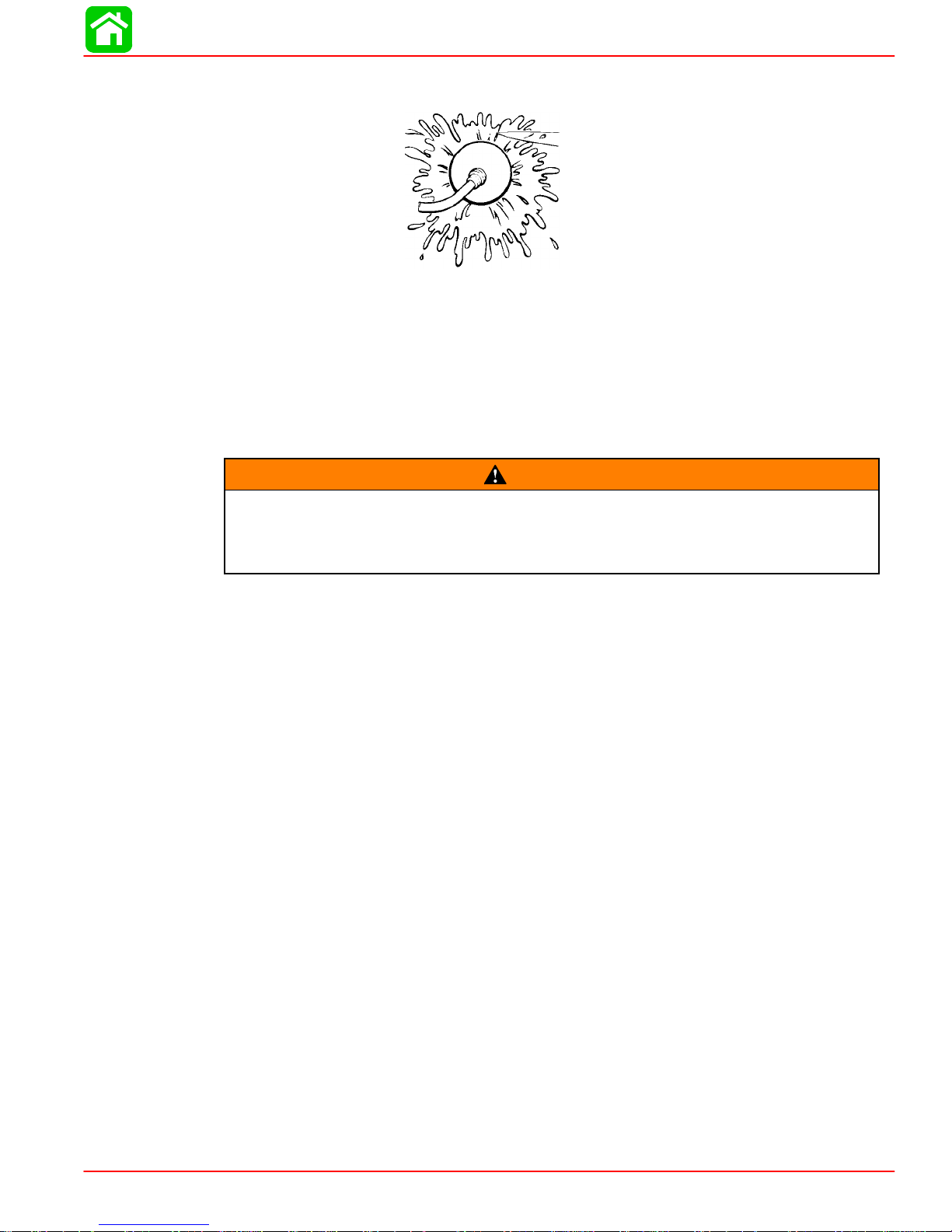
4. Adjust water flow (if necessary) so excess water continues leaking out from around
5. Checkfor asteady stream ofwater flowingoutof thewater pumpindicatorhole. Con-
6. Stopthe engine,turn offthe water, andremove theflushing attachment.Reinstall the
Fuel System
MAINTENANCE
therubbercupstoensuretheengine isreceivinganadequatesupplyofcoolingwater.
tinue flushingthe outboard for 3 to 5 minutes,carefully monitoring watersupply at all
times.
propeller.
WARNING
Avoidserious injury or death fromgasoline fire or explosion. Carefullyfollow all
fuel system service instructions. Always stop the engine and DO NOT smoke or
allow open flames or sparks in the area while servicing any part of the fuel system.
Beforeservicinganypartofthefuelsystem,stop engine anddisconnectthebattery.Drain
the fuelsystem completely. Use an approved containerto collect andstore fuel.Wipe up
any spillageimmediately.Material usedto containspillage must bedisposed of inan approved receptacle. Anyfuel system service must be performed in a well ventilated area.
Inspect any completed service work for sign of fuel leakage.
Fuel Line Inspection
Visuallyinspectthe fuellineandprimer bulbforcracks, swelling,leaks,hardness orother
signsof deterioration ordamage.If anyoftheseconditions isfound,the fuellineorprimer
bulb must be replaced.
Engine Fuel Filter
Inspectthe sightbowl forwater accumulationand inspectthe filter elementfor sediment.
Clean filter as follows.
REMOVAL
1. Hold onto the cover to prevent it from turning.
2. Turn off the sight bowl.
3. Pull out the filter element and wash it with cleaning solvent.
90-826883R2 JUNE 1998 Page 1B-5
Page 14
MAINTENANCE
INSTALLATION
1. Push the filter element (with open end toward cover) into cover.
2. Place the O-ring seal into the sight bowl and screw the sight bowl hand tight intothe
cover.
1
3/4
3. Visually inspect for fuel leakage around the sight bowl by squeezing the primer bulb
until firm, forcing fuel into the sight bowl.
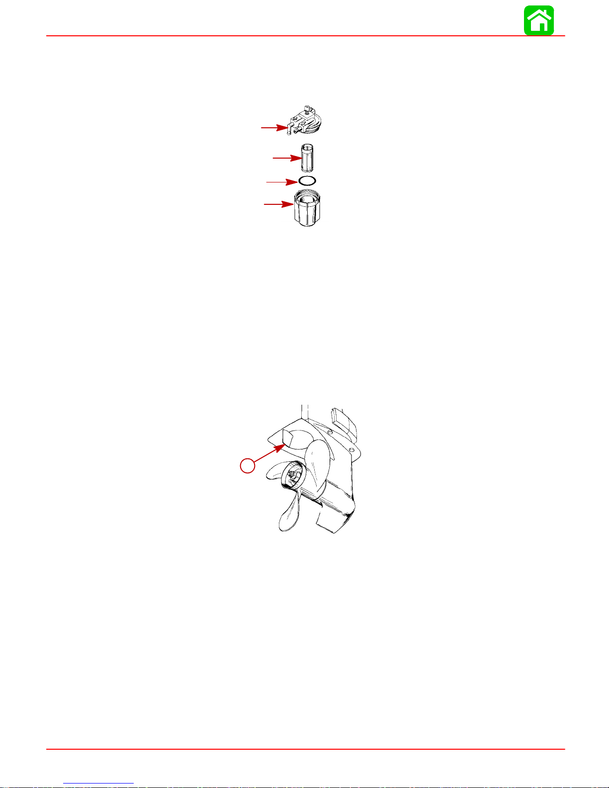
Corrosion Control Anode
Your outboard has a corrosion control anode installed to the gear case. An anode helps
protecttheoutboardagainstgalvaniccorrosionbysacrificingitsmetaltobeslowlyeroded
instead of the outboard metals.
5
2
The anode requires periodic inspection especially in salt water which will accelerate the
erosion.Tomaintainthis corrosionprotection, alwaysreplace theanode beforeit iscompletely eroded.Never paint or apply a protective coatingon the anode as this will reduce
effectiveness of the anode.
a
a - Anode
Page 1B-6 90-826883R2 JUNE 1998
Page 15
Spark Plug Inspection
Inspect spark plugs at the recommended intervals.
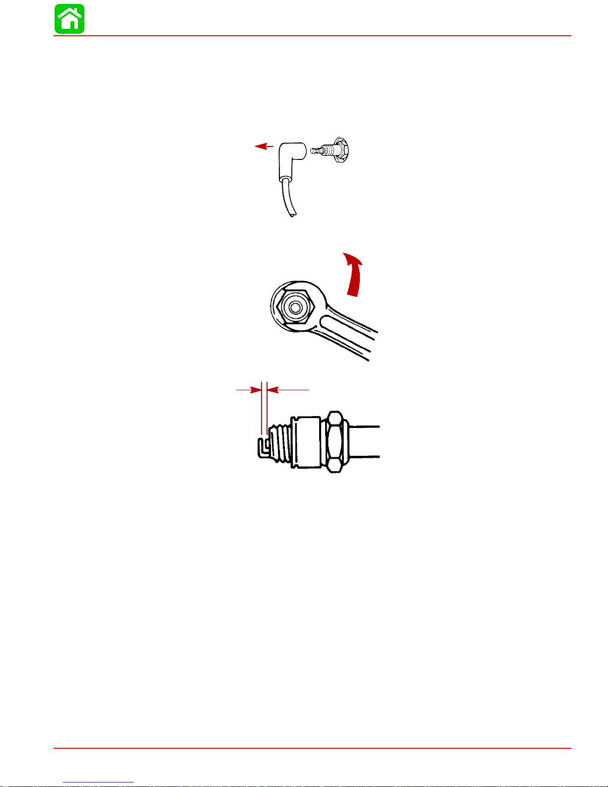
1. Remove the spark plug leads by twisting the rubber boots slightly and pull off.
2. Removethe sparkplugs to inspectand clean.Replace sparkplug ifelectrode isworn
or the insulator is rough, cracked, broken, blistered or fouled.
MAINTENANCE
3. Set the spark plug gap. See Specification Chart in General Information Section.
4. Before reinstalling sparkplugs, clean away dirt on the spark plug seats. Install plugs
finger tight, and tighten 1/4 turn or torque to 20 lb. ft. (27.1 N·m).
Battery Inspection
Thebattery shouldbe inspected atperiodic intervalstoensure properengine startingcapability.
IMPORTANT: Read the safety and maintenance instructions which accompany
your battery.
1. Turn off the engine before servicing the battery.
2. Add water as necessary to keep the battery full.
3. Make sure the battery is secure against movement.
4. Batterycable terminals shouldbeclean,tight, andcorrectlyinstalled.Positive topositive and negative to negative.
5. Make sure thebattery is equipped with anonconductive shield to prevent accidental
shorting of battery terminals.
90-826883R2 JUNE 1998 Page 1B-7
Page 16
MAINTENANCE
Fuse Replacement -- Electric Start Remote Control Models
The electric startingcircuit is protected from overload by a SFE 20 AMP fuse.If the fuse
is blown,the electric starter motor will not operate.Try to locate and correctthe cause of
the overload. If the cause is not found, the fuse may blow again. Replace the fuse with
a fuse of the same rating.
Replace with a new SFE 20 AMP fuse.
Lubrication Points
Lubricate Points 1 thru 6 with Quicksilver 2-4-C Marine Lubricant with Teflon or
Special Lubricant 101.
1. Steering Friction Adjustment Shaft (Tiller Handle Models) -- Lubricate fitting.
2. Swivel Bracket -- Lubricate fitting.
1
2
3. Transom Clamp Screws -- Lubricate threads.
Page 1B-8 90-826883R2 JUNE 1998
Page 17

MAINTENANCE
4. Tilt Tube -- Lubricate fittings.
5. Lubricate the throttle and shaft cables, moving components and pivot locations.
WARNING
The end of the steering cable must be fully retracted into the outboard tilt tube
before adding lubricant. Adding lubricant to steering cable when fully extended
could cause steering cable to become hydraulically locked. An hydraulically
lockedsteering cable willcauseloss ofsteeringcontrol, possibly resultinginserious injury or death.
6. SteeringCableGreaseFitting (IfEquipped)--Rotatesteering wheeltofullyretractthe
steering cable end (a) into the outboard tilt tube. Lubricate through fitting (b).
Lubricate points 7 With Light Weight Oil
7. Steering Link Rod Pivot Points -- Lubricate points.
6-b
7
6-a
90-826883R2 JUNE 1998 Page 1B-9
Page 18
MAINTENANCE
Lubricate Point 8 with Quicksilver Anti-Corrosion Grease or 2-4-C Marine Lubricant with Teflon.
8. Propeller Shaft -- Refer to Propeller Replacement for removal and installation of the
propeller. Coat the entire propeller shaft with lubricant to prevent the propeller hub
from corroding to the shaft.
8
Gear Case Lubrication
Gear Case Lubricant Capacity
Draining Gear Case
When adding or changing gear case lubricant, visually check for the presence of water
inthelubricant.If waterispresent,itmay have settledtothebottomand willdrainoutprior
tothelubricant,or itmaybemixed withthelubricant,givingit amilkycoloredappearance.
Ifwater isnoticed, have thegear casecheckedby yourdealer.Waterinthe lubricant may
resultinprematurebearingfailureor,in freezingtemperatures, will turn toice anddamage
the gear case.
Whenever you remove the fill/drain plug, examine the magnetic end for metal particles.
A smallamount of metalfilings or finemetal particles indicatesnormal gear wear. An excessive amount of metal filings or larger particles (chips) may indicate abnormal gear
wear and should be checked by an authorized dealer.
Gear Case Ratio Capacity
2.25:1 8.8 fl. oz. (260.0ml)
Page 1B-10 90-826883R2 JUNE 1998
Page 19
Draining Gear Case
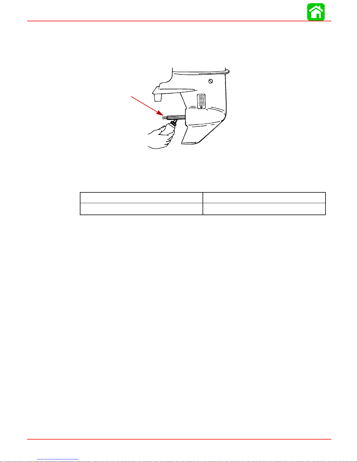
1. Place outboard in a vertical operating position.
2. Place drain pan below outboard.
3. Remove fill/drain plug (a) and vent plug (b) and drain lubricant.
a
Checking Lubricant Level and Refilling Gear Case
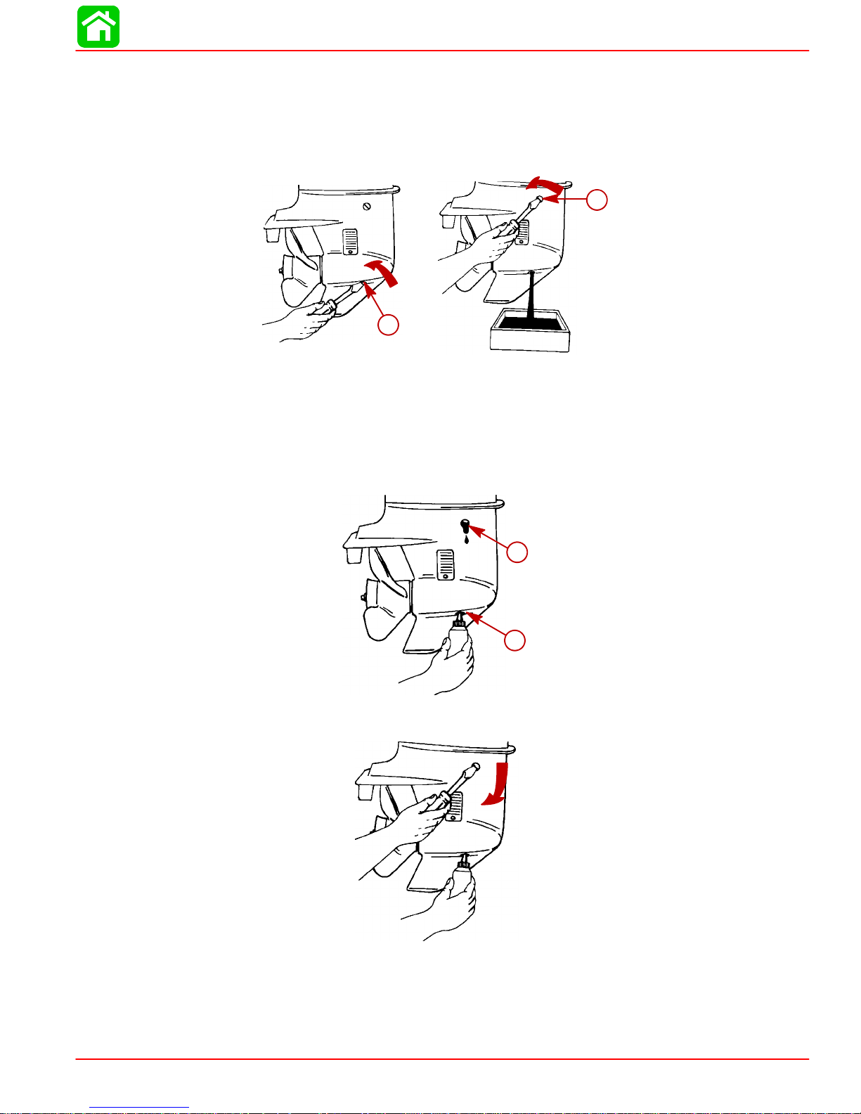
1. Place outboard in a vertical operating position.
2. Remove vent plug from vent hole (a).
MAINTENANCE
b
3. Place lubricant tube into the fill hole (b) and add lubricant until it appears at the vent
hole (a).
a
b
4. Stop adding lubricant. Install the vent plug and sealing washer before removing the
lubricant tube.
90-826883R2 JUNE 1998 Page 1B-11
Page 20
MAINTENANCE
5. Remove lubricant tube and reinstall cleaned fill/drain plug and sealing washer.
Storage Preparations
Fuel System
IMPORTANT: Gasoline containing alcohol (ethanol or methanol) can cause a formation of acid during storage and can damage the fuel system. If the gasoline being used contains alcohol, It is advisable to drain as much of the remaining gasoline as possible from the fuel tank, remote fuel line, and engine fuel system.
Fillthe fuel system(tank,hoses, fuel pumps,andfuelinjection systems)withtreated(stabilized)fuel tohelp prevent formationof varnishand gum.Proceedwith followinginstructions.
1. PortableFuel Tank--Pourthe requiredamountof Quicksilver GasolineStabilizer(followinstructionsoncontainer) intofueltank.Tipfueltankback and forthtomixstabilizer with the fuel.
2. Permanently InstalledFuel Tank -- Pour the required amountof Quicksilver Gasoline
Stabilizer(follow instructionson container) intoa separatecontainerand mixwith approximately one quart (one liter) of gasoline. Pour this mixture into fuel tank.
3. Placethe outboard inwater orconnectflushing attachment forcirculating coolingwater. Run the engine for ten minutes to allow treated fuel to fill the fuel system.
Protecting External Engine Components
1. Lubricate all outboard componentslisted in the Inspection and Maintenance Schedule.
2. Touch up any paint nicks.
3. SprayQuicksilverCorrosionGuard on externalmetalsurfaces(exceptcorrosioncontrol anodes).
Protecting Internal Engine Components
NOTE: Before performingSteps 1 and 2, make surethe fuel system hasbeen prepared
for storage.
1. Placethe outboard inwater orconnectflushing attachment forcirculating coolingwater. Start the engine and let it run in neutral to warm up.
2. With engine running at fast idle, stop the fuel flow by disconnecting the remote fuel
line.Whenenginebegins tostall,quicklysprayQuicksilver Storage Sealintocarburetor until engine stops from lack of fuel.
3. Remove the spark plugs and inject a five second spray of Quicksilver Storage Seal
around the inside of each cylinder.
Page 1B-12 90-826883R2 JUNE 1998
Page 21

4. Rotate the flywheelmanually several times to distribute the storage seal inthe cylinders. Reinstall spark plugs.
Gear Case
Drain and refill the gear case lubricant (refer to maintenance procedure).
Positioning Outboard for Storage
Store outboard in an upright position to allow water to drain out of outboard.
If outboard is stored tilted up in freezing temperature, trapped cooling water or
rain water that may have entered the propeller exhaust outlet in the gear case
could freeze and cause damage to the outboard.
Battery Storage
1. Follow the battery manufacturers instructions for storage and recharging.
2. Remove the battery from the boat and check water level. Recharge if necessary.
3. Store the battery in a cool, dry place.
4. Periodically check the water level and recharge the battery during storage.
MAINTENANCE
CAUTION
90-826883R2 JUNE 1998 Page 1B-13
Page 22
GENERAL INFORMATION
IMPORTANT INFORMATION
Section 1C - General Information
Table of Contents
Table of Contents 1C-1. . . . . . . . . . . . . . . . . . . . . . . . . . . .
Serial Number Location 1C-1. . . . . . . . . . . . . . . . . . . . . . .
Conditions Affecting Performance 1C-2. . . . . . . . . . . . . .
Weather 1C-2. . . . . . . . . . . . . . . . . . . . . . . . . . . . . . . . . .
Boat 1C-3. . . . . . . . . . . . . . . . . . . . . . . . . . . . . . . . . . . . .
Engine 1C-4. . . . . . . . . . . . . . . . . . . . . . . . . . . . . . . . . . .
Following Complete Submersion 1C-5. . . . . . . . . . . . . . .
Submerged While Running
(Special Instructions) 1C-5. . . . . . . . . . . . . . . . . . . . . .
Salt Water Submersion (Special Instructions) 1C-5.
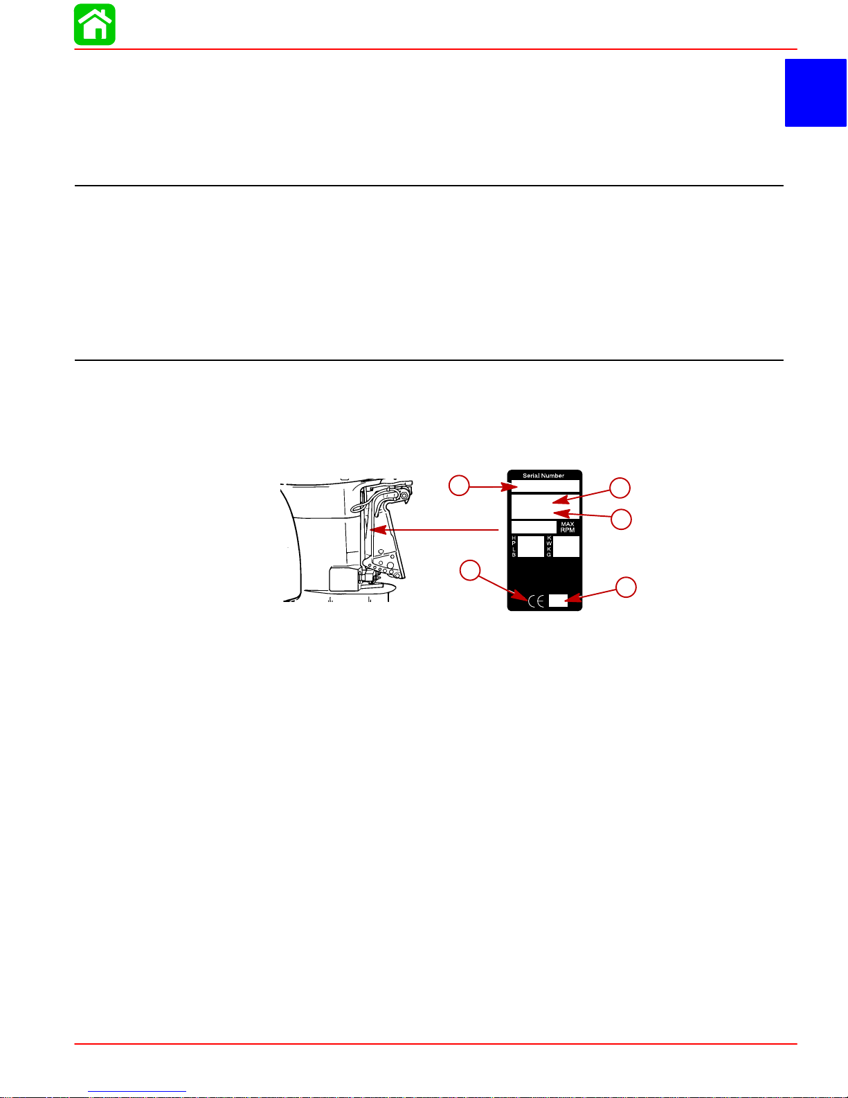
Serial Number Location
The Outboard serial number is located on the lower starboard side of the engine block.
A serial number is also located on the starboard side of the swivel bracket.
1
C
Fresh Water Submersion (Special Instructions) 1C-5
Propeller Selection 1C-6. . . . . . . . . . . . . . . . . . . . . . . . . . .
Propeller Removal/Installation 1C-7. . . . . . . . . . . . . . . . .
Compression Check 1C-9. . . . . . . . . . . . . . . . . . . . . . . . . .
Painting Procedures 1C-10. . . . . . . . . . . . . . . . . . . . . . . .
Cleaning & Painting Aluminum Propellers
& Gear Housings 1C-10. . . . . . . . . . . . . . . . . . . . . . . .
Decal Application 1C-1 1. . . . . . . . . . . . . . . . . . . . . . . . . . . .
Decal Removal 1C-11. . . . . . . . . . . . . . . . . . . . . . . . . . .
Instructions for “Wet” Application 1C-11. . . . . . . . . . .
a - Serial Number
b - Model Year
c - Model Description
d - Year Manufactured
e - Certified Europe Insignia
a
OGXXXXXX
19XX
XXXX
b
c
e
d
XX
90-826883R2 JUNE 1998 Page 1C-1
Page 23
GENERAL INFORMATION
Conditions Affecting Performance
Weather
It is a known fact that weather conditions exert a profound effect on power output of internal combustion engines. Therefore, established horsepower ratings refer to the power
that the engine will produce at its rated RPM under a specific combination of weather conditions.
Corporations internationally have settled on adoption of I.S.O. (International Standards
Organization) engine test standards, as set forth in I.S.O. 3046 standardizing the computation of horsepower from data obtained on the dynamometer, correcting all values to the
power that the engine will produce at sea level, at 30% relative humidity at 77° F (25°C)
temperature and a barometric pressure of 29.61 inches of mercury.
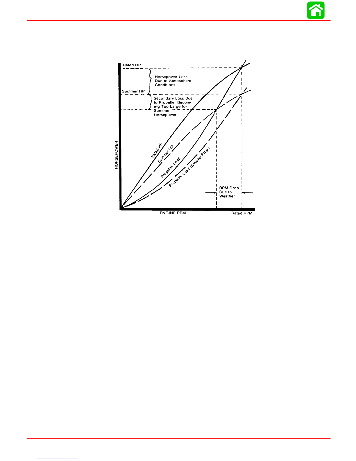
Summer Conditions of high temperature, low barometric pressure and high humidity all
combine to reduce the engine power. This, in turn, is reflected in decreased boat speeds-as much as 2 or 3 miles-per-hour (3 or 5 Km per-hour) in some cases. (Refer to previous
chart.) Nothing will regain this speed for the boater, but the coming of cool, dry weather.
In pointing out the practical consequences of weather effects, an engine--running on a
hot, humid summer day--may encounter a loss of as much as 14% of the horsepower it
would produce on a dry , brisk spring or fall day. The horsepower , that any internal combustion engine produces, depends upon the density of the air that it consumes and, in turn,
this density is dependent upon the temperature of the air, its barometric pressure and water vapor (or humidity) content.
Accompanying this weather-inspired loss of power is a second but more subtle loss. At
rigging time in early spring, the engine was equipped with a propeller that allowed the engine to turn within its recommended RPM range at full throttle. With the coming of the summer weather and the consequent drop in available horsepower, this propeller will, in effect, become too large. Consequently , the engine operates at less than its recommended
RPM.
Page 1C-2 90-826883R2 JUNE 1998
Page 24

Due to the horsepower/RPM characteristics of an engine, this will result in further loss of
horsepower at the propeller with another decrease in boat speed. This secondary loss,
however, can be regained by switching to a smaller pitch propeller that allows the engine
to again run at recommended RPM.
For boaters to realize optimum engine performance under changing weather conditions,
it is essential that the engine have the proper propeller to allow it to operate at or near the
top end of the recommended maximum RPM range at wide-open-throttle with a normal
boat load.
Not only does this allow the engine to develop full power, but equally important is the fact
that the engine also will be operating in an RPM range that discourages damaging detonation. This, of course, enhances overall reliability and durability of the engine.
Boat
WEIGHT DISTRIBUTION
1. Proper positioning of the weight inside the boat (persons and gear) has a significant
effect on the boat’s performance, for example:
a. Shifting weight to the rear (stern)
GENERAL INFORMATION
(1.)Generally increases top speed.
(2.)If in excess, can cause the boat to porpoise.
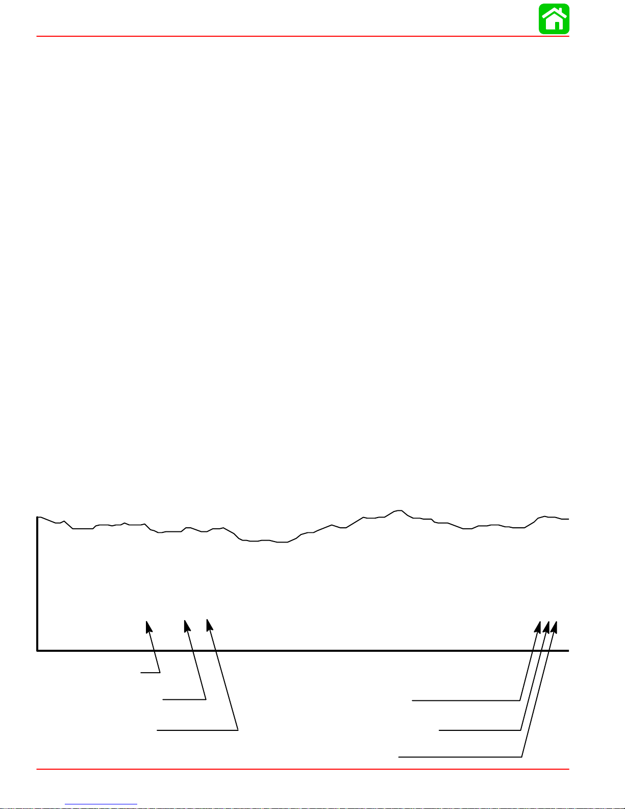
BOTTOM
For maximum speed, a boat bottom should be nearly a flat plane where it contacts the
water and particularly straight and smooth in fore-and-aft direction.
1. Hook: Exists when bottom is concave in fore-and-aft direction when viewed from the
2. Rocker: The reverse of hook and much less common. “Rocker” exists if bottom is con-
3. Surface Roughness: Moss, barnacles, etc., on boat or corrosion of outboard’s gear
WATER ABSORPTION
It is imperative that all through hull fasteners be coated with a quality marine sealer at time
of installation. Water intrusion into the transom core and/or inner hull will result in additional boat weight (reduced boat performance), hull decay and eventual structural failure.
(3.)Can make the bow bounce excessively in choppy water.
(4.)Will increase the danger of the following - wave splashing into the boat when
coming off plane.
b. Shifting weight to the front (bow)
(1.)Improves ease of planing off.
(2.)Generally improves rough water ride.
(3.)If excessive, can make the boat veer left and right (bow steer).
side. When boat is planing, “hook” causes more lift on bottom near transom and allows
bow to drop, thus greatly increasing wetted surface and reducing boat speed. “Hook”
frequently is caused by supporting boat too far ahead of transom while hauling on a
trailer or during storage.
vex in fore-and-aft direction when viewed from the side, and boat has strong tendency
to porpoise.
housing increase skin friction and cause speed loss. Clean surfaces when necessary .
90-826883R2 JUNE 1998 Page 1C-3
Page 25

GENERAL INFORMATION
CAVITATION
Engine
DETONATION
Cavitation is caused by water vapor bubbles forming either from a sharp edge or angle
on the gear case or from an irregularity in the propeller blade itself. These vapor bubbles
flow back and collapse when striking the surface of the propeller blade resulting in the erosion of the propeller blade surface. If allowed to continue, eventual blade failure (breakage) will occur.
Detonation in a 2-cycle engine resembles the “pinging” heard in an automobile engine.
It can be otherwise described as a tin-like “rattling” or “plinking” sound.
Detonation is an explosion of an unburned portion of the fuel/air charge after the spark
plug has fired. Detonation creates severe shock waves in the engine, and these shock
waves often find or create a weakness: The dome of a piston, cylinder head/gasket, piston
rings or piston ring lands, piston pin and roller bearings.
A few of the most common causes of detonation in a marine 2-cycle application are as
follows:
• Over-advanced ignition timing.
• Use of low octane gasoline.
• Propeller pitch too high (engine RPM below recommended maximum range).
• Lean fuel mixture at or near wide-open-throttle.
• Spark plugs (heat range too hot - incorrect reach - cross-firing).
• Inadequate engine cooling (deteriorated cooling system).
• Combustion chamber/piston deposits (result in higher compression ratio).
Detonation usually can be prevented if:
1. The engine is correctly set up.
2. Diligent maintenance is applied to combat the detonation causes.
Damaged Piston Resulting from Detonation
Page 1C-4 90-826883R2 JUNE 1998
51115
Page 26

Following Complete Submersion
Submerged While Running (Special Instructions)
When an engine is submerged while running, the possibility of internal engine damage
is greatly increased. If, after engine is recovered and with spark plugs removed, engine
fails to turn over freely when turning flywheel, the possibility of internal damage (bent connecting rod and/or bent crankshaft) exists. If this is the case, the powerhead must be disassembled.
Salt Water Submersion (Special Instructions)
Due to the corrosive effect of salt water on internal engine components, complete disassembly is necessary before any attempt is made to start the engine.
Fresh Water Submersion (Special Instructions)
1. Recover engine as quickly as possible.
2. Remove cowling.
3. Flush exterior of outboard with fresh water to remove mud, weeds, etc. DO NOT attempt to start engine if sand has entered powerhead, as powerhead will be severely
damaged. Disassemble powerhead if necessary to clean components.
GENERAL INFORMATION
4. Remove spark plugs and get as much water as possible out of powerhead. Most water
can be eliminated by placing engine in a horizontal position (with spark plug holes
down) and rotating flywheel.
5. Pour alcohol into carburetor throats (alcohol will absorbed water). Again rotate flywheel.
6. Turn engine over and pour alcohol into spark plug openings and rotate flywheel.
7. Turn engine over (place spark plug openings down) and pour engine oil into throat of
carburetors while rotating flywheel to distribute oil throughout crankcase.
8. Again turn engine over and pour approximately one teaspoon of engine oil into each
spark plug opening. Again rotate flywheel to distribute oil in cylinders.
9. Remove and clean carburetors and fuel pump assembly.
10. Dry all wiring and electrical components using compressed air.
1 1. Disassemble the engine starter motor and dry the brush contacts, armature and other
corrodible parts.
12. Reinstall spark plugs, carburetors and fuel pump.
13. Attempt to start engine, using a fresh fuel source. If engine starts, it should be run for
at least one hour to eliminate any water in engine.
14. If engine fails to start, determine cause (fuel, electrical or mechanical). Engine should
be run within 2 hours after recovery of outboard from water, or serious internal damage may occur. If unable to start engine in this period, disassemble engine and clean
all parts. Apply oil as soon as possible.
Propeller Selection
For in-depth information on marine propellers and boat performance - written by marine
engineers - see your Authorized Dealer for the illustrated “What You Should Know
About Quicksilver Propellers... and Boat Performance Information” (Part No.
90-86144).
90-826883R2 JUNE 1998 Page 1C-5
Page 27

GENERAL INFORMATION
For best all around performance from your outboard/boat combination, select a propeller
that allows the engine to operate in the upper half of the recommended full throttle RPM
range with the boat normally loaded (refer to Specifications). This RPM range allows for
better acceleration while maintaining maximum boat speed.
If changing conditions cause the RPM to drop below the recommended range (such as
warmer, more humid weather, operation at higher elevations, increased boat load or a
dirty boat bottom/gear case) a propeller change or cleaning may be required to maintain
performance and ensure the outboard’s durability.
Check full-throttle RPM using an accurate tachometer with the engine trimmed out to a
balanced-steering condition (steering effort equal in both directions) without causing the
propeller to “break loose”.
Refer to “Quicksilver Accessory Guide” for a complete list of available propellers.
1. Select a propeller that will allow the engine to operate at or near the top of the recommended full throttle RPM range (listed in “Specifications,” preceding) with a normal
load. Maximum engine speed (RPM) for propeller selection exists when boat speed
is maximum and trim is minimum for that speed. (High RPM, caused by an excessive
trim angle, should not be used in determining correct propeller.) Normally, there is a
150-350 RPM change between propeller pitches.
2. If full throttle operation is below the recommended range, the propeller MUST BE
changed to one with a lower pitch to prevent loss of performance and possible engine
damage.
3. After initial propeller installation, the following common conditions may require that
the propeller be changed to a lower pitch:
a. Warmer weather and great humidity will cause an RPM loss.
b. Operating in a higher elevation causes an RPM loss.
c. Operating with a damaged propeller or a dirty boat bottom or gear housing will
cause an RPM loss.
d. Operation with an increased load (additional passengers, equipment, pulling ski-
ers, etc.).
Page 1C-6 90-826883R2 JUNE 1998
Page 28
Propeller Removal/Installation
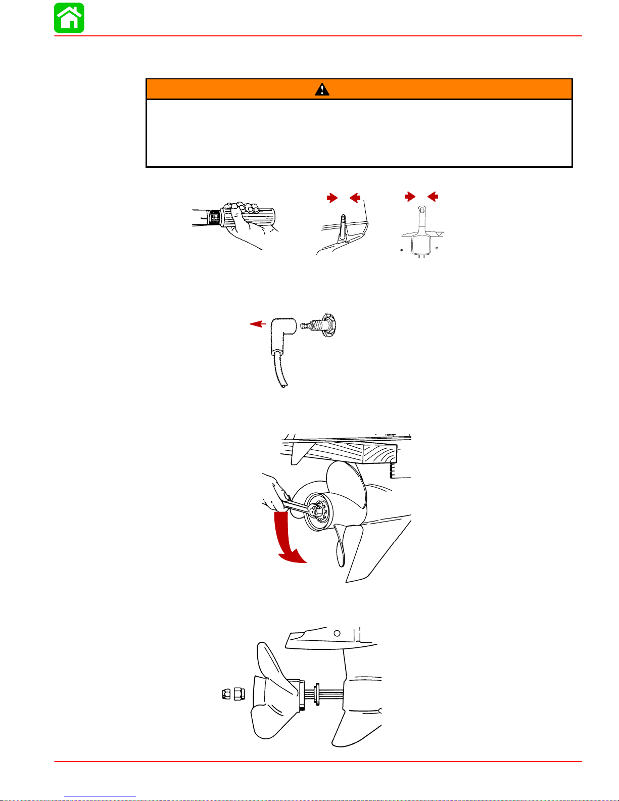
If the propeller shaft is rotated while the engine is in gear, there is the possibility
that the engine will crank over and start. T o prevent this type of accidental engine
starting and possible serious injury caused from being struck by a rotating propeller, always shift outboard to neutral position and remove spark plug leads
when you are servicing the propeller
1. Shift outboard to neutral position.
GENERAL INFORMATION
WARNING
N
2. Remove the spark plug leads to prevent engine from starting.
3. Place a block of wood between gear case and propeller to hold propeller and remove
propeller nut.
N
4. Pull propeller straight off shaft. If propeller is seized to the shaft and cannot be removed, have the propeller removed by an authorized dealer.
90-826883R2 JUNE 1998 Page 1C-7
Page 29
GENERAL INFORMATION
5. Coat the propeller shaft with Quicksilver Anti-Corrosion Grease or 2-4-C Marine Lubricant with Teflon.
IMPORTANT: To prevent the propeller hub from corroding and seizing to the propeller shaft, especially in salt water, always apply a coat of the recommended lubricant to the entire propeller shaft at the recommended maintenance intervals and
also each time the propeller is removed.
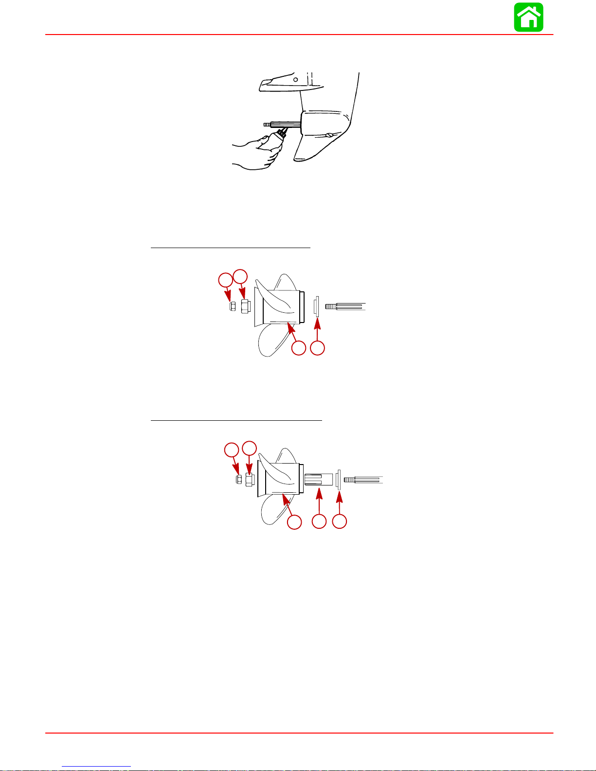
6. Flo-Torque I Drive Hub Propellers
– Install forward thrust hub, propeller, rear thrust
hub and propeller nut onto the shaft.
c
d
a
b
a - Forward Thrust Hub
b - Propeller
c - Rear Thrust Hub
d - Propeller Nut
7. Flo-Torque II Drive Hub Propellers – Install forward thrust hub, replaceable drive
sleeve propeller, rear thrust hub and propeller nut onto the shaft.
d
e
a
b
c
a - Forward Thrust Hub
b - Replaceable Drive Sleeve
c - Propeller
d - Rear Thrust Hub
e - Propeller Nut
Page 1C-8 90-826883R2 JUNE 1998
Page 30
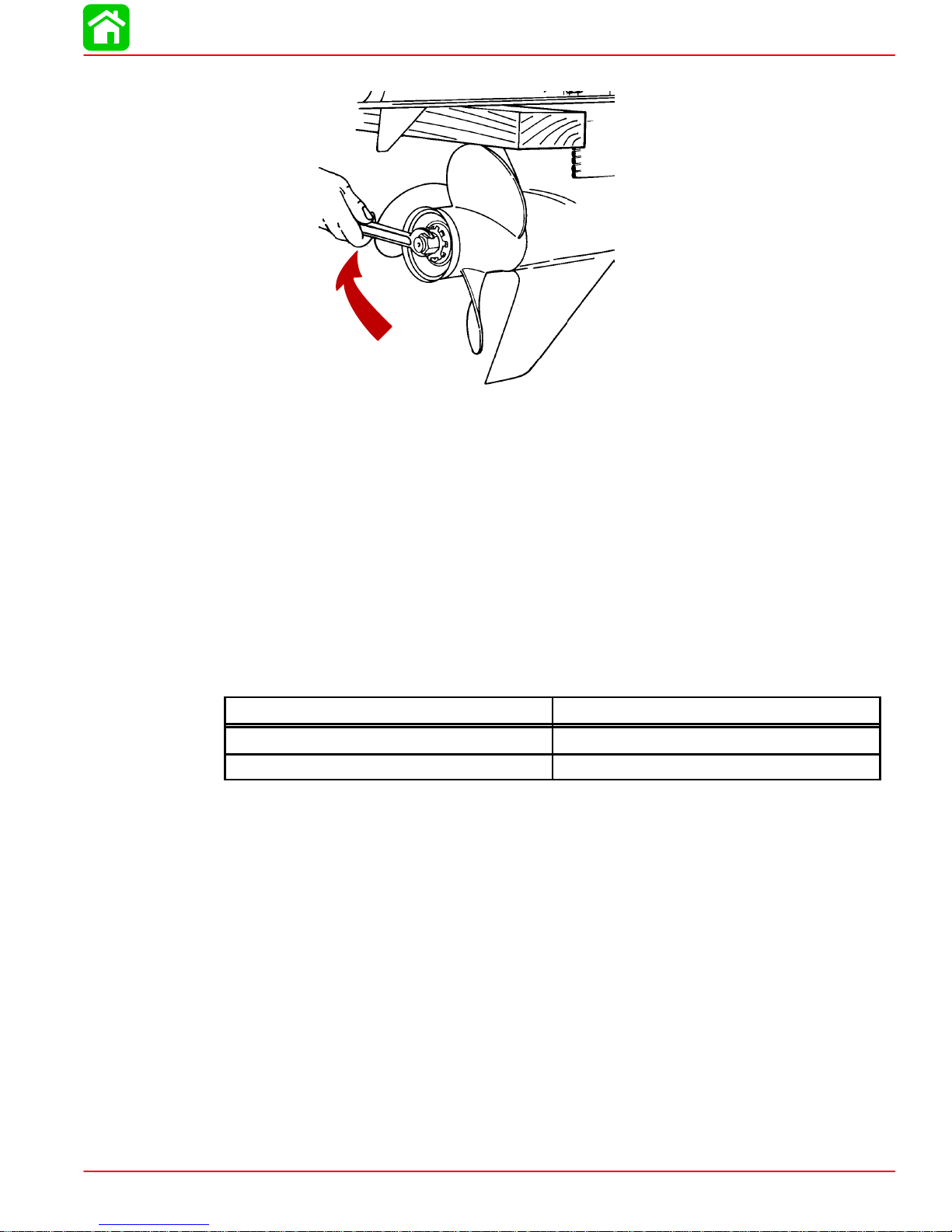
8. Place a block of wood between gear case and propeller and tighten propeller nut.
Compression Check
1. Remove spark plugs.
2. Install compression gauge in spark plug hole.
GENERAL INFORMATION
3. Hold throttle plate at W.O.T.
4. Crank the engine over until the compression reading peaks on the gauge. Record the
reading.
5. Check and record compression of each cylinder. The highest and lowest reading
recorded should not differ by more than 15% (see example chart below). A reading
below 120 psi might indicate a total engine wear problem.
Example of compression test differences
Maximum (psi)
Minimum (psi)
180 162
150 127.5
6. Compression check is important because an engine with low or uneven compression
cannot be tuned successfully to give peak performance. It is essential, therefore, that
improper compression be corrected before proceeding with an engine tuneup.
7. Cylinder scoring: If powerhead shows any indication of overheating, such as discolored or scorched paint, visually inspect cylinders for scoring or other damage as outlined in Section 4 “Powerhead.”
90-826883R2 JUNE 1998 Page 1C-9
Page 31

GENERAL INFORMATION
Painting Procedures
Cleaning & Painting Aluminum Propellers & Gear Housings
WARNING
Avoid serious injury from flying debris. A void serious injury from airborne particles. Use eye and breathing protection with proper ventilation.
PROPELLERS
1. Sand the entire area to be painted with 3M 120 Regalite Polycut or coarse ScotchBrite, disc or belts.
2. Feather edges of all broken paint edges. Try not to sand through the primer.
3. Clean the surface to be painted using PPG Industries DX330 Wax and Grease Remover or equivalent (Xylene or M.E.K.).
4. If bare metal has been exposed, use Quicksilver’s Light Gray Primer.
5. Allow a minimum of 1 hour dry time and no more than 1 week before applying the finish
coat.
6. Apply the finish coat using Quicksilver’s EDP Propeller Black.
GEAR HOUSINGS
The following procedures should be used in refinishing gear housings. This procedure will
provide the most durable paint system available in the field. The materials recommended
are of high quality and approximate marine requirements. The following procedure will
provide a repaint job that compares with a properly applied factory paint finish. It is recommended that the listed materials be purchased from a local Ditzler Automotive Finish Supply Outlet. The minimum package quantity of each material shown following is sufficient
to refinish several gear housings.
Procedure:
1. Wash gear housing with a muriatic acid base cleaner to remove any type of marine
growth, and rinse with water, if necessary.
2. Wash gear housing with soap and water, then rinse.
3. Sand blistered area with 3M 180 grit sandpaper or P180 Gold Film Disc to remove
paint blisters only. Feather edge all broken paint edges.
4. Clean gear housing thoroughly with (DX-330) wax and grease remover.
5. Spot repair surfaces where bare metal is exposed with (DX-503) alodine treatment.
IMPORT ANT : Do not use any type of aerosol spray paints as the paint will not properly adhere to the surface nor will the coating be sufficiently thick to resist future
paint blistering.
6. Mix epoxy chromate primer (DP-40) with equal part catalyst (DP-401) per manufacturers instructions, allowing proper induction period for permeation of the epoxy primer and catalyst.
7. Allow a minimum of one hour drying time and no more than one week before top coating assemblies.
8. Use Ditzler Urethane DU9000 for Mercury Black, DU34334 for Mariner Grey, and
DU35466 for Force Charcoal, and DU33414M for Sea Ray White. Catalyze all three
colors with Ditzler DU5 catalyst mixed 1:1 ratio. Reduce with solvents per Ditzler label.
Page 1C-10 90-826883R2 JUNE 1998
Page 32

Be sure to comply with instructions on the label for ventilation and respirators.
Using a spray gun, apply one half to one mil even film thickness. Let dry , flash off
for five minutes and apply another even coat of one half to one mil film thickness.
This urethane paint will dry to the touch in a matter of hours, but will remain sensitive to scratches and abrasions for a few days.
9. The type of spray gun used will determine the proper reduction ratio of the paint.
IMPORTANT: Do not paint sacrificial zinc trim tab or zinc anode.
10. Cut out a cardboard “plug” for trim tab pocket to keep paint off of mating surface to
maintain good continuity circuitry between trim tab and gear housing.
Decal Application
Decal Removal
1. Mark decal location before removal to assure proper alignment of new decal.
2. Carefully soften decal and decal adhesive with a heat gun or heat blower while removing old decal.
GENERAL INFORMATION
CAUTION
3. Clean decal contact area with a 1:1 mixture of isopropyl alcohol and water.
4. Thoroughly dry decal contact area and check for a completely cleaned surface.
Instructions for “Wet” Application
NOTE: The following decal installation instructions are provided for a “Wet” installation.
All decals should be applied wet.
TOOLS REQUIRED
1. Plastic Squeegee*
2. Stick Pin
3. Dish Washing Liquid/Detergent without ammonia** “Joy” and “Drift” are known to
be compatible for this process.
** Automotive Body Filler Squeegee
** Do not use a soap that contains petroleum based
solvents.
SERVICE TIP: Placement of decals using the “Wet” application will allow time to
position decal. Read entire installation instructions on this technique before proceeding.
TEMPERATURE
IMPORTANT: Installation of vinyl decals should not be attempted while in direct
sunlight. Air and surface temperature should be between 60°F (15°C) and 100°F
(38°C) for best application.
SURFACE PREPARATION
IMPORT ANT: Do not use a soap or any petroleum based solvents to clean application surface.
Clean entire application surface with mild dish washing liquid and water. Rinse surface
thoroughly with clean water.
90-826883R2 JUNE 1998 Page 1C-1 1
Page 33

GENERAL INFORMATION
DECAL APPLICATION
1. Mix
NOTE: Leave protective masking, if present, on the face of decal until final steps of decal
installation. This will ensure that the vinyl decal keeps it’s shape during installation.
2. Place the decal face down on a clean work surface and remove the paper backing
3. Using a spray bottle, flood the entire “adhesive side” of the decal with the pre-mixed
4. Flood area where the decal will be positioned with wetting solution.
5. Position pre-wetted decal on wetted surface and slide into position.
6. Starting at the center of the decal, “lightly” squeegee out the air bubbles and wetting
7. Wipe decal surface with soft paper towel or cloth.
8. Wait 10 - 15 minutes.
9. Starting at one corner, “carefully and slowly” pull the masking of f the decal surface at
1
/2 ounce (16 ml) of dish washing liquid in one gallon (4 l) of cool water to use as
wetting solution.
from “adhesive side” of decal.
wetting solution.
solution with overlapping strokes to the outer edge of the decal. Continue going over
the decal surface until all wrinkles are gone and adhesive bonds to the cowl surface.
a 180° angle.
NOTE: T o remove any remaining bubbles, pierce the decal at one end of the bubble with
stick pin and press out the entrapped air or wetting solution with your thumb (moving toward the puncture).
Page 1C-12 90-826883R2 JUNE 1998
Page 34

OUTBOARD MOTOR INSTALLATION
IMPORTANT INFORMATION
Section 1D - Outboard Motor Installation
Table of Contents
Table of Contents 1D-1. .. .. .. .. .. .. .. .. .. .. .. .. .. .
Notice to Installer and Owner 1D-1. . . . . . . . . . . . . . . . . .
Boat Horsepower Capacity 1D-1.. .. .. .. .. .. .. .. .
Outboard Remote Control 1D-1. .. .. .. .. .. .. .. .. .
Selecting Accessories For The Outboard 1D-2. . . . .
Selecting Steering Cables and Remote Control
Cables 1D-2. . . . . . . . . . . . . . . . . . . . . . . . . . . . . . . . . . . . .
Installing Outboard 1D-3. .. .. .. .. .. .. .. .. .. .. .. .. .
Steering Cable and Steering Link Rod Installation 1D-4
Installing Ride Guide Steering Cable to
the Outboard 1D-4.. . . . . . . . . . . . . . . . . . . . . . . . . . . .
Steering Cable Seal 1D-4. .. .. .. .. .. .. .. .. .. .. ..
Steering Link Rod Installation 1D-5. . . . . . . . . . . . . . .
Notice to Installer and Owner
1
D
Remote Control Installation 1D-6. . . . . . . . . . . . . . . . . . .
Shift and Throttle Cable Installation to
the Outboard 1D-6. . . . . . . . . . . . . . . . . . . . . . . . . . . . . . .
Shift Cable Installation 1D-6. . . . . . . . . . . . . . . . . . . . .
Throttle Cable Installation 1D-7. . . . . . . . . . . . . . . . . .
Remote Wiring Harness Connection to Engine 1D-8. . .
Battery Cable Connections 1D-10. . . . . . . . . . . . . . . . . . .
Propeller Installation 1D-11. .. .. .. .. .. .. .. .. .. .. .. .
Tilt Pin Adjustment 1D-11. .. .. .. .. .. .. .. .. .. .. .. .. .
Placing Tilt Pin in Lower Holes 1D-11.. .. .. .. .. .. .
Placing Tilt Pin in Upper Holes 1D-12.. .. .. .. .. .. .
Trim Tab Adjustment 1D-12.. .. .. .. .. .. .. .. .. .. .. ..
Thismanualaswellassafetylabelspostedon the outboardusethefollowingsafetyalerts
to draw your attention to special safety instructions that should be followed.
DANGER -- Immediate hazards which WILL result in severe personal injury or death.
WARNING-- HazardsorunsafepracticeswhichCOULDresultinseverepersonalinjury
or death.
CAUTION -- Hazards or unsafe practices which could result in minor injury or product
or property damage.
Boat Horsepower Capacity
U.S. COAST GUARD CAPACITY
MAXIMUM HORSEPOWER XXX
MAXIMUM PERSON
CAPACITY (POUNDS) XXX
MAXIMUM WEIGHT
CAPACITY XXX
DANGER
WARNING
CAUTION
Do not overpower or overload your boat. Most boats will carry a required capacity plate
indicating the maximum acceptable power and load as determined by the manufacturer
following certainfederal guidelines. If in doubt, contact your dealer or the boat manufacturer.
90-826883R2 JUNE 1998 Page 1D-1
Page 35

OUTBOARD MOTOR INSTALLATION
WARNING
Using an outboard that exceeds the maximum horsepower limit of a boat can: 1.
cause loss of boat control 2. place too much weight at the transom altering the
designed flotation characteristics of the boat or 3. cause the boat to break apart
particularly around the transom area. Overpowering a boat can result in serious
injury, death, or boat damage.
Outboard Remote Control
Theremotecontrolconnectedtoyouroutboardmustbeequipped witha start-in-gearprotection device. This prevents the engine from starting when the outboard is in gear.
WARNING
Avoidseriousinjuryordeath from asuddenunexpectedacceleration whenstarting your engine. The design of this outboard requires that the remote control
used with it must have a built in start-in-gear protection device.
Selecting Accessories For The Outboard
Genuine Mercury Marine Quicksilver Accessories have been specifically designed and
tested for your outboard.
Mercury Marine Quicksilver accessories are available from Mercury Marine dealers.
Some accessories not manufactured or sold by Mercury Marine are not designed to be
safelyusedwithyouroutboardoroutboard operating system.Acquireandreadtheinstallation, operation, and maintenance manuals for all your selected accessories.
Selecting Steering Cables and Remote Control Cables
Installsteering mountand steeringwheel inaccordance withinstallation instructionsthat
accompany each.
IMPORTANT: Steering cable must be correct length. Sharp bends on too-short of
a cable result in “kinks;” too-long of a cable require unnecessary bends and/or
loops. Both conditions place extra stress on the cable.
Refer to “Quicksilver Accessories Guide” to determine correct length of steering cable.
Page 1D-2 90-826883R2 JUNE 1998
Page 36

Installing Outboard
1. Measure the transom height of your boat. The boat bottom should be aligned or be
within 1 in. (25mm) above the anti-ventilation plate (a) of the outboard.
a
a - Anti-Ventilation Plate
2. Place outboard on center line of transom.
OUTBOARD MOTOR INSTALLATION
0 -1in.
(0 - 25mm)
3. Tighten transom clamp handles.
4. To prevent loss of outboard overboard, fasten outboard by drilling two 5/16 in. (7.9
mm)holesthroughthetransomusingtransomclampholes as atemplate.Fastenwith
two bolts,flat washers and locknuts. Use a marinewaterproofing sealer inholes and
around bolts to make the installation water tight.
a
c
b
a - Bolts (2)
b - Flat Washers(2)
c - Locknuts (2)
90-826883R2 JUNE 1998 Page 1D-3
Page 37

OUTBOARD MOTOR INSTALLATION
Steering Cable and Steering Link Rod Installation
Installing Ride Guide Steering Cable to the Outboard
IMPORTANT: Before installing steering cable into tilt tube, lubricate entire cable
end with Quicksilver 2-4-C w/Teflon Marine Lubricant (92-825407A12).
1. Lubricate the entire cable end.
a
a - Quicksilver 2-4-C Marine Lubricant with Teflon
2. Insert steering cable end thru outboard tilt tube and secure steering cableto tilt tube
with steering cable attaching nut as shown. Torque nut to 35 lb. ft. (47.5 N·m).
Steering Cable Seal
3. Place amark on tilt tube5/8 in. (15.9mm) from port end of tube. Slideplastic spacer,
o-ring and cap over steering cable end, to tilt tube on engine.
b
a - Cable End
b - Attaching Nut [Torque to 35 lb. ft. (47.5 N·m)].
1/4 in.
(6.4mm
)
b
c
a
d
a - Mark
b - Spacer
c - O-ring
d - Cap
Page 1D-4 90-826883R2 JUNE 1998
a
Page 38
4. Thread cap up to the 1/4 in. (6.4mm) mark.
a - Cap
Steering Link Rod Installation
IMPORTANT: The steering link rod that connects the steering cable to the engine
mustbe fastened usingspecialwasher head bolt(“a” --PartNumber 10-14000)and
self locking nuts (“b” & “c” -- Part Number 11-34863). These locknuts must never
be replaced with common nuts (non locking) as they will work loose and vibrate
off freeing the link rod to disengage.
OUTBOARD MOTOR INSTALLATION
a
WARNING
Disengagement of a steering link rod can result in the boat takinga full, sudden,
sharp turn. This potentially violent action can cause occupants to be thrown
overboard exposing them to serious injury or death.
1. Assemblesteering linkrod to steeringcable withtwo flatwashers (d)andnylon insert
locknut(“b” -- Part Number 11-34863).Tighten locknut (b) untilit seats,then backnut
off 1/4 turn.
2. Assemblesteeringlinkrod toenginewithspecialwasher head bolt(“a”-- PartNumber
10-14000)and nyloninsertlocknut (“c” --Part Number11-34863).Firsttorquebolt (a)
to 20 lb. ft. (27.1 N·m), then torque locknut (c) to 20 lb. ft. (27.1 N·m).
c
d
b
a - Bolt (10-14000)
b - Lock Nut (11-34863)
c - Lock Nut (11-34863)
d - Washers (2 each)
90-826883R2 JUNE 1998 Page 1D-5
a
Page 39
OUTBOARD MOTOR INSTALLATION
WARNING
After installation is complete (and before operating outboard), check that boat
willturn right whensteeringwheel isturned right andthat boat willturn left when
steering wheelis turned left. Check steeringthru full range (left and right) and at
all tilt angles to assure interference-free movement.
Remote Control Installation
Refer to Quicksilver Accessory Guide for appropriate electric or manual remote control.
Use instructions provided with control for proper installation.
Shift and Throttle Cable Installation to the Outboard
Installthe shift cableandthrottle cableintotheremote controland mounttheremote control following instructions which are provided with the remote control.
NOTE: Install the shift cable before thethrottle cable. The shift cable is the first cable to
move when the remote control handle is moved into gear.
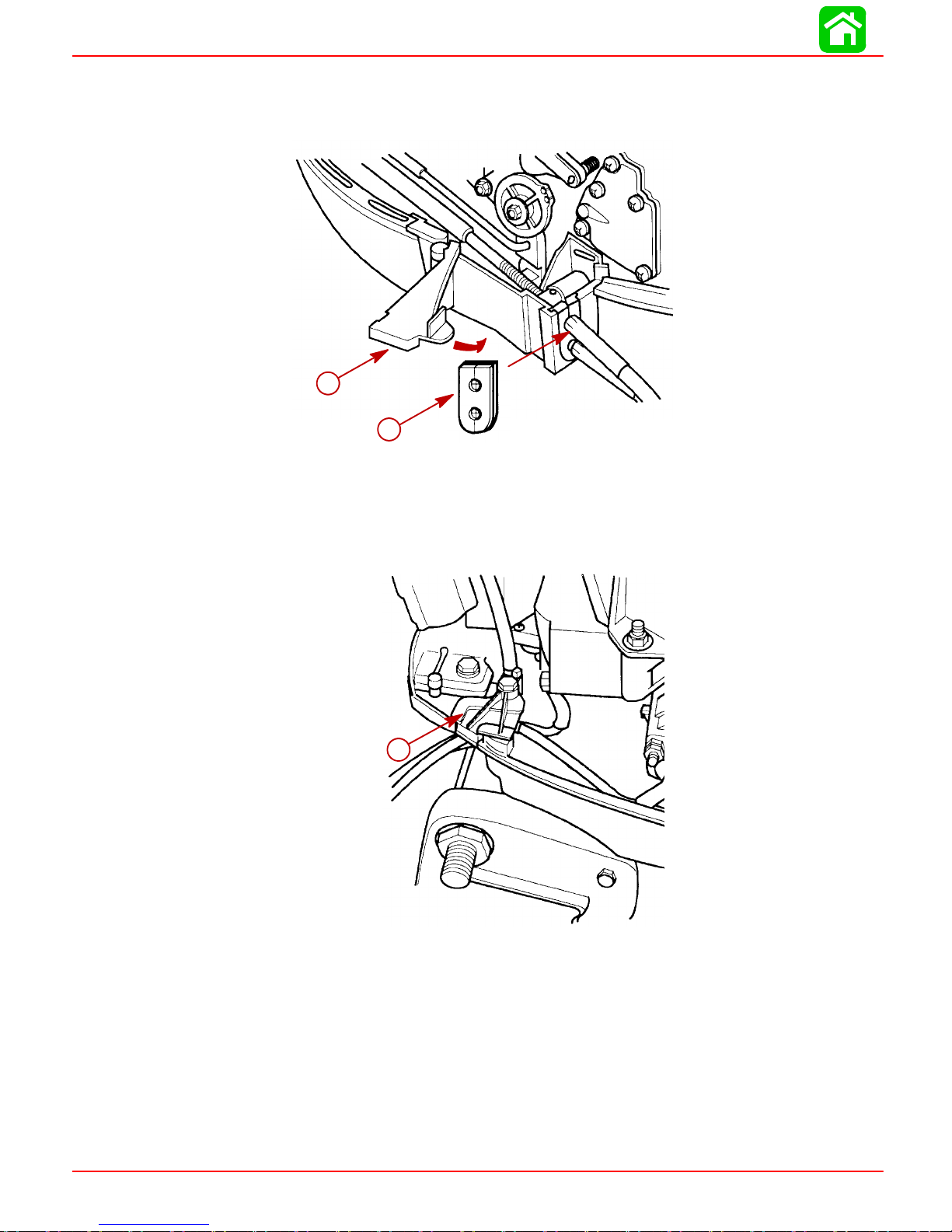
Shift Cable Installation
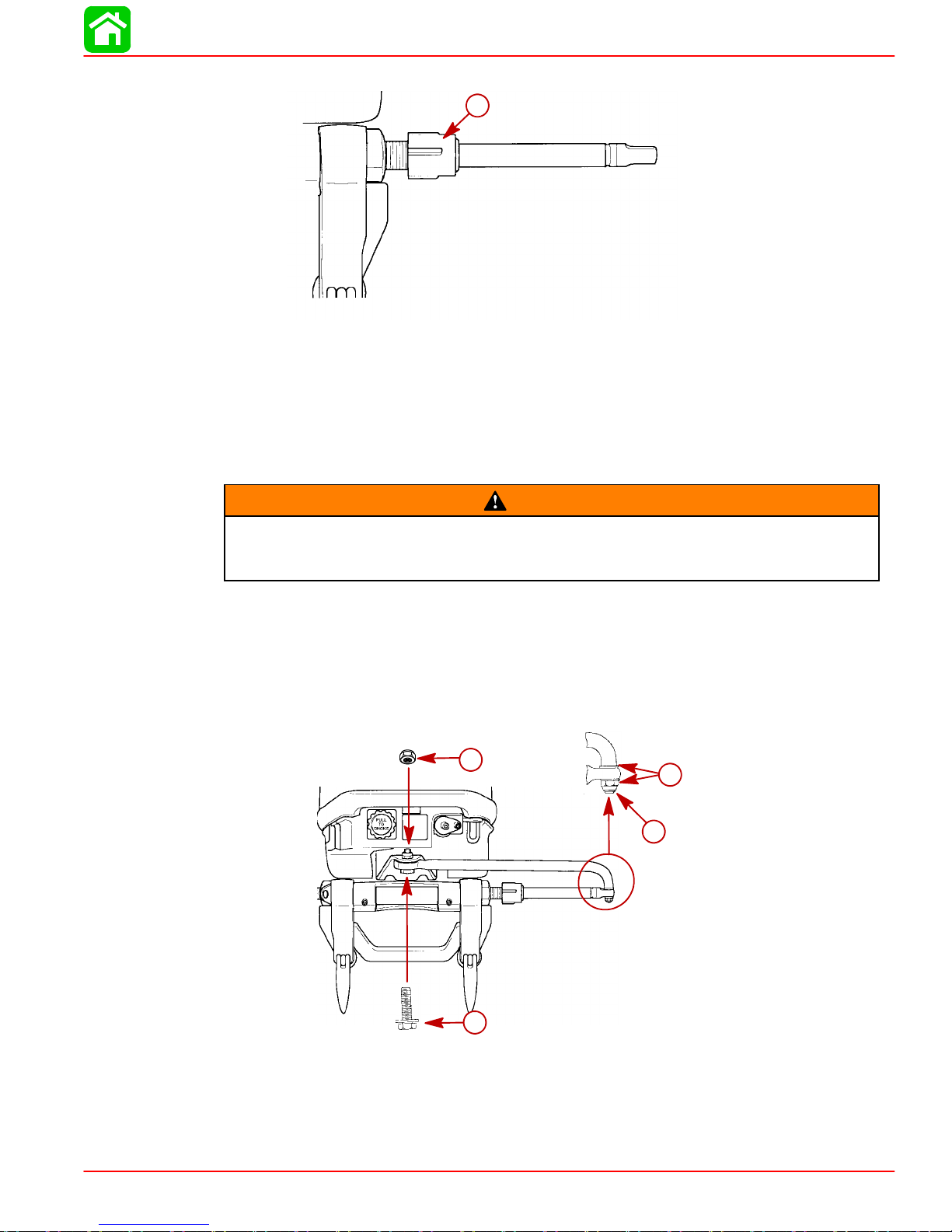
1. Move the remote control handle into full reverse position.
2. Place the engine shift lever (a) into reverse position (toward rear) while rotating propeller. The propeller shaft will not rotate in either direction when in reverse position.
3. Open up the cable retainer cover (b) and remove the barrel holder and front rubber
grommet.
4. Installthe shiftcable (c) ontotheshift leverpin (d). lockinplace withretainer latch(e).
5. Adjust theshift cablebarrel so itwill fit intothe bottom holeof the barrelholder (f)and
that thebarrel holder will slide freely into theretaining pocket without pre-loading the
shift cable.
f
a
b
a - Shift Lever
b - Cable Retainer Cover
c - Shift Cable
d - Shift Lever Pin
e - Retainer Latch
f - Barrel Holder
6. Check shift cable adjustments as follows:
Page 1D-6 90-826883R2 JUNE 1998
e
d
c
Page 40

a. With remote control shifted into forward the propeller shaft should lock solidly in
gear. If it does not, adjust the cable barrel closer to the engine shift lever.
b. Shift remote control into neutral. The propeller shaft should turn freely without
drag.If not,adjust the barrelaway fromthe engineshift lever. Repeatsteps aand
b.
c. Shift remote control into reverse while turning the propeller shaft. The propeller
shaftshould locksolidlyin gear. Ifnot,adjust thebarrelaway fromtheengine shift
lever. Repeat steps a thru c.
d. Return remote control handle to neutral. The propeller shaft should turn freely
withoutdrag. Ifnot, adjustthe barrelcloser tothe engineshift lever.Repeatsteps
a thru d.
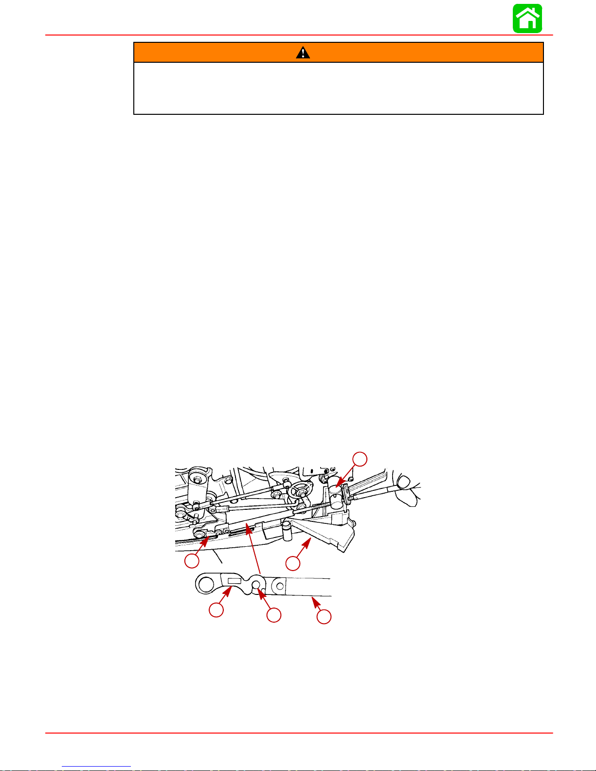
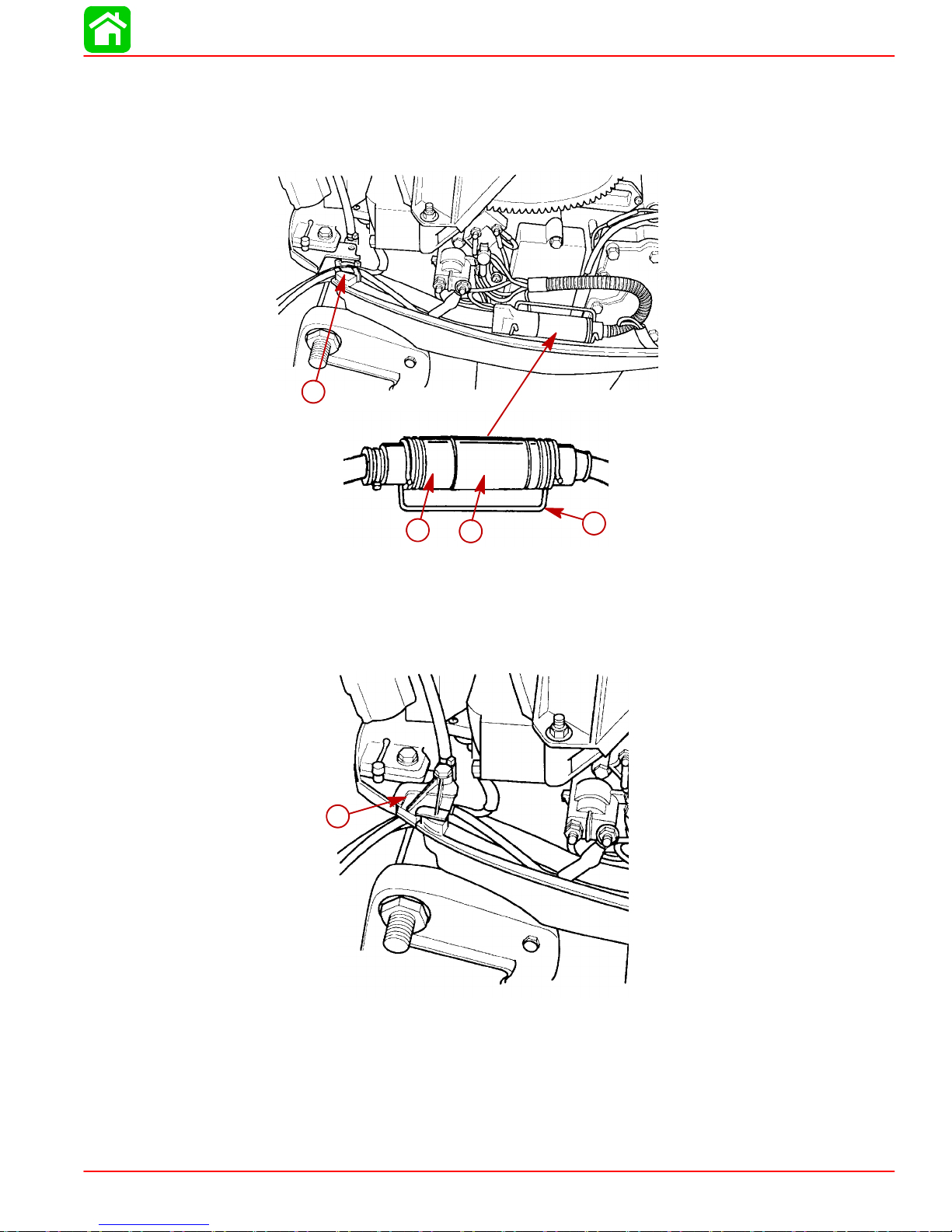
Throttle Cable Installation
NOTE: Attach Shift cable to engine prior to attaching throttle cable.
1. Position the remote control handle forward, to wide-open-throttle position.
2. Installthe throttle cable(a)onto thethrottlepin(b). lockinplace withretainerlatch(c).
3. Move throttle lever (g) until tab (e) contacts throttle stop (f). Adjust the barrel on the
throttle cable so that the barrel will fit into the barrel holder (d).
4. Slipthebarrelinto thebarrelholderandplacethe barrelholderintotheretainingpocket.
OUTBOARD MOTOR INSTALLATION
5. Check the throttle cable adjustment as follows.
a. Move the remote control handle back to neutral a few times and then return the
handle back to forward wide-open-position.
b. Recheck to make sure tab (e) is contacting throttle stop (f).
f
e
d
g
a - Throttle Cable
b - Throttle Pin
c - Retainer Latch
d - Barrel Holder
e - Tab
f - Throttle Stop
g - Throttle Lever
90-826883R2 JUNE 1998 Page 1D-7
c
b
a
Page 41
OUTBOARD MOTOR INSTALLATION
6. Place the rubber seal ( side with holes towards front)) onto the control cables and
install control cables, barrel holder and rubber seal into the cable holder as shown.
7. Lock the barrel holder in place with the cable retainer latch.
a - Rubber Seal
b - Cable Retainer Latch
b
a
Remote Wiring Harness Connection to Engine
1. Remove wire retainer from the bottom cowl.
a
a - Wire Retainer
Page 1D-8 90-826883R2 JUNE 1998
Page 42
OUTBOARD MOTOR INSTALLATION
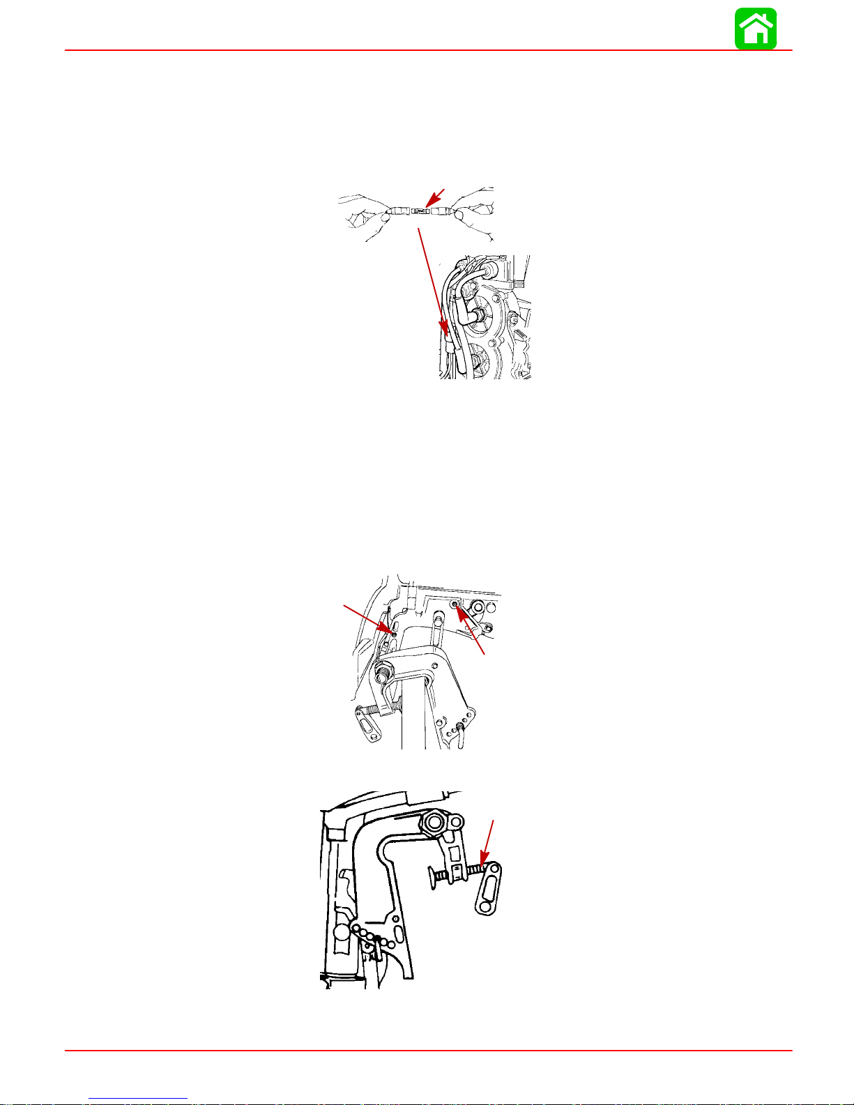
2. Position the remote wiring harness and battery cables thru the bottom cowl rubber
grommet as shown.
3. Plug the remote wiring harness into the engine wiring harness connector.
4. Secure the connection together using retainer.
a
b c
a - Rubber Grommet
b - Remote Wiring Harness
c - Engine Harness Connector
d - Retainer
d
5. Fasten the remote wiring harness and battery cables into the bottom cowl rubber
grommet with retainer.
a
a - Retainer
90-826883R2 JUNE 1998 Page 1D-9
Page 43
OUTBOARD MOTOR INSTALLATION
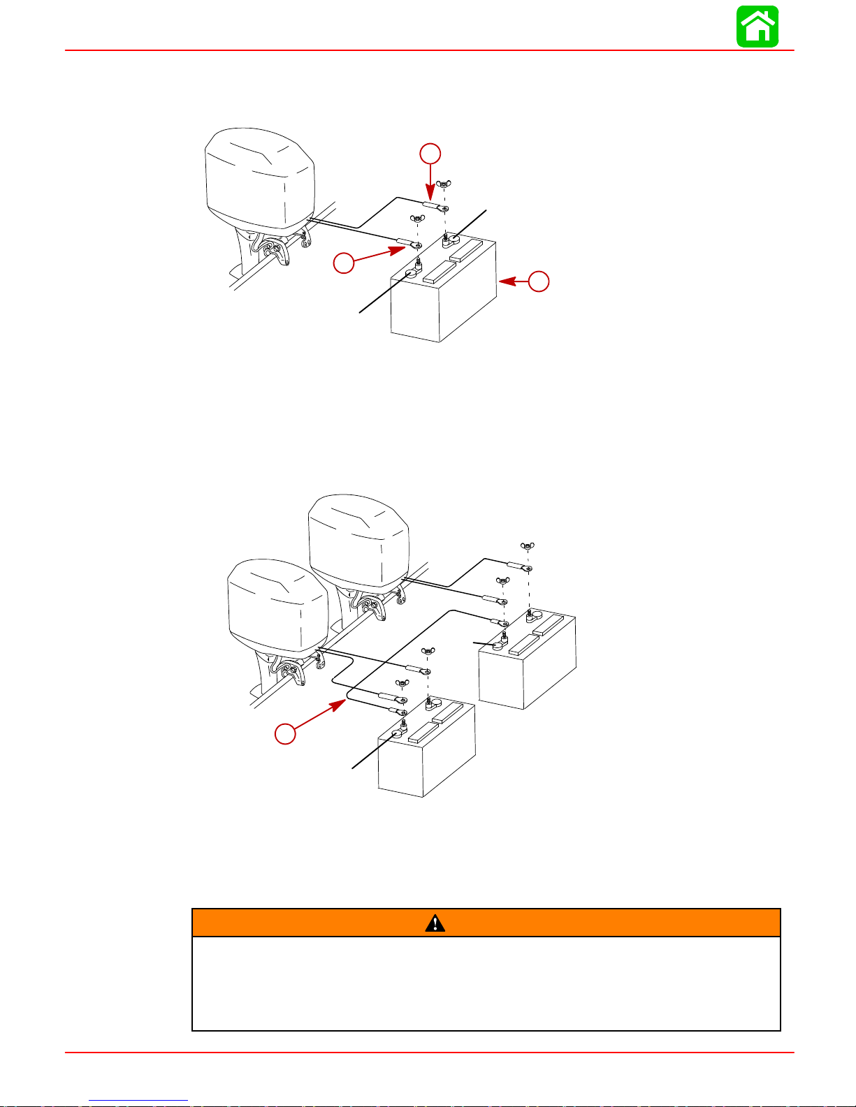
Battery Cable Connections
SINGLE OUTBOARD
b
(--)
a - RED Sleeve (POSITIVE)
b - BLACK Sleeve (NEGATIVE)
c - Starting Battery
DUAL OUTBOARD
1. Connecta commonground cable(wire sizesame asengine batterycables) between
negative (--) terminals on starting batteries.
a
(+)
c
a
a - Ground Cable (Same Wire Size As Engine Battery Cable -- Connect Between Negative (--)
Terminals
Propeller Installation
If thepropeller shaft isrotated while the engine is ingear,there is thepossibility
thatthe engine willcrankover andstart.Topreventthistype of accidentalengine
starting and possible serious injury caused from being struck by a rotating propeller, always shift outboard to neutral position and remove spark plug leads
when you are servicing the propeller.
(--)
(--)
WARNING
Page 1D-10 90-826883R2 JUNE 1998
Page 44

Flo-Torq I Drive Hub Propellers
c
d
a - Forward Thrust Hub
b - Propeller
c - Rear Thrust Hub
d - Propeller Nut -- Tighten
Flo-Torq II Drive Hub Propellers
d
e
OUTBOARD MOTOR INSTALLATION
a
b
a - Forward Thrust Hub
b - Replaceable Drive Sleeve
c - Propeller
d - Rear Thrust Hub
e - Propeller Nut -- Tighten
Tilt Pin Adjustment
Placing Tilt Pin in Lower Holes
1. Lower the bow.
2. Result in quicker planing off, especially with a heavy load or a stern heavy boat.
3. Generally improve the ride in choppy water.
b
c
a
4. Increasesteering torque orpulltothe right(withthenormal righthandrotationpropeller).
5. Inexcess,lowerthe bowofsomeboatsto a pointatwhichtheybegin toplowwiththeir
bow inthe waterwhile on plane.This can result in anunexpected turn in either direction called “bow steering” or “over-steering” if any turn is attempted or if a significant
wave is encountered.
90-826883R2 JUNE 1998 Page 1D-11
Page 45

OUTBOARD MOTOR INSTALLATION
Placing Tilt Pin in Upper Holes
1. Lift the bow out of the water.
2. Generally increase top speed.
3. Increase clearance over submerged objects or a shallow bottom.
4. Increasesteering torqueor pullto theleft at anormal installationheight (withthe normal right hand rotation propeller).
5. In excess, cause boat “porpoising” (bouncing) or propeller ventilation.
Trim Tab Adjustment
Propellersteering torquemay causeboat topull inone direction.This steering torqueresults from outboard not being adjusted so the propeller shaft is parallel to the water surface.Thetrimtabcanhelpcompensateforthis steering torqueandcanbeadjustedwithin
limits to reduce any unequal steering effort.
NOTE: Trim tab adjustmentwill have little effect reducingsteering torque if theoutboard
is installed with the anti-ventilation plate ap proximately 2 inches (50mm) or more above
the boat bottom.
Operateboatatnormalcruisingspeed,withtheoutboard set atthedesiredtransomangle
adjustment. Turn boat left and right and note the direction the boat turns more easily.
If adjustment isnecessary, loosentrim tab bolt and make small adjustments ata time. If
the boat turns more easily to the left, move the trailing edge of trim tab to the left. If the
boatturns moreeasily to theright movethetrailing edgeof trimtab tothe right. Retighten
bolt and retest.
Page 1D-12 90-826883R2 JUNE 1998
Page 46

Table of Contents
IGNITION
ELECTRICAL
Section 2A - Ignition
2
Specifications 2A-2. . . . . . . . . . . . . . . . . . . . . . . . . . . . . . .
Special Tools 2A-3. . . . . . . . . . . . . . . . . . . . . . . . . . . . . . .
Ignition/Electrical Components 2A-4. . . . . . . . . . . . . . . .
Ignition Description 2A-6.. .. .. .. .. .. .. .. .. .. .. .. ..
Electronic Spark Advance 2A-7. . . . . . . . . . . . . . . . . .
Mechanical Spark Advance 2A-7. . . . . . . . . . . . . . . .
15XD RPM Limiter 2A-7. .. .. .. .. .. .. .. .. .. .. .. .
Ignition Component Description 2A-7. . . . . . . . . . . . . . . .
Trigger Coil 2A-7. . . . . . . . . . . . . . . . . . . . . . . . . . . . . .
Stator 2A-8. . . . . . . . . . . . . . . . . . . . . . . . . . . . . . . . . . .
Flywheel 2A-8. . . . . . . . . . . . . . . . . . . . . . . . . . . . . . . .
Ignition Coil 2A-9.. . . . . . . . . . . . . . . . . . . . . . . . . . . . .
Ignition Switch Box 2A-9. . . . . . . . . . . . . . . . . . . . . . . .
Electronic Spark Advance 2A-11. .. .. .. .. .. .. .. .. ..
Ignition Test Procedures 2A-12. . . . . . . . . . . . . . . . . . . . .
Direct V oltage Adapter (DVA) 2A-12. . . . . . . . . . . . . .
Ignition Troubleshooting 2A-13. . . . . . . . . . . . . . . . . . . . .
Ignition Diagnostic Procedures 2A-13. . . . . . . . . . . . . . .
Ignition Troubleshooting 2A-15. . . . . . . . . . . . . . . . . . . . .
Electronic Spark Advance 2A-15. .. .. .. .. .. .. .. ..
Tool: Multimeter/DVA Tester 91-99750A1 2A-15. .. .
Ignition Troubleshooting 2A-16. . . . . . . . . . . . . . . . . . . . .
Mechanical Spark Advance 2A-16. . . . . . . . . . . . . . .
Ignition Troubleshooting (RED Stator) 2A-17. . . . . . . . .
A
90-826883 R2 JUNE 1998 Page 2A-1
Page 47

IGNITION
Specifications
IGNITION
SYSTEM
Readings taken @
68°F (20°C).
Type
Spark Plug Type (NGK)
Spark Plug Gap
Spark Plug Hex
Firing Order
20 Jet 19941/2THRU 1998
20/25 19941/2THRU 1996
Electronic Spark Advance
Idle @ 750 ± 50 RPM (In Forward
Gear)
Fast Idle Speed
Maximum BTDC (Running)
Setup Timing
Stator High Speed Winding
Stator Low Speed Winding
Diode Test
Ignition Coil Resistance:
Primary
Secondary (w/o Boots)
20 Jet 1999 and Newer
20/25 1997/98 Models
Mechanical Spark Advance
Idle @ 750 ± 50 RPM (In Forward
Gear)
Fast Idle Speed
Maximum BTDC (Running)
Stator High Speed Winding
Stator Low Speed Winding
Diode Test
Ignition Coil Resistance:
Primary
Secondary (w/o Boots)
Trigger
Capacitor Discharge Ignition
NGK BP8H-N-10
0.040 in. (1.0 mm)
18 mm
1-2
4° ± 2° B.T.D.C (Not Adjustable)
1400 RPM ± 250 RPM
25° ± 1 @5500 RPM
28° B.T.D.C. @ 3000 ± 200 R.P.M.
(Set-up timing of 28° B.T.D.C. will be
retarded to 25° B.T.D.C. @ 5500 R.P.M.)
100 -- 180 W (RED -- BLK)
2900 -- 3500 W (BLUE -- BLACK)
2800 -- 3400 W (RED -- BLUE)
0 W
850 -- 1200 W
6° ± 1° B.T.D.C
1500 RPM ± 200 RPM
25° ± 1 @5500 RPM
120 - 180 W (BLK/WHT - GRD)
3200 - 3800 W (BLK/YEL - GRD)
3100 -- 3700 W (BLK/YEL - BLK/WHT)
0.02 - 0.04 W
8000 - 11000 W
6500 - 8500 W
Page 2A-2 90-826883R2 JUNE 1998
Page 48
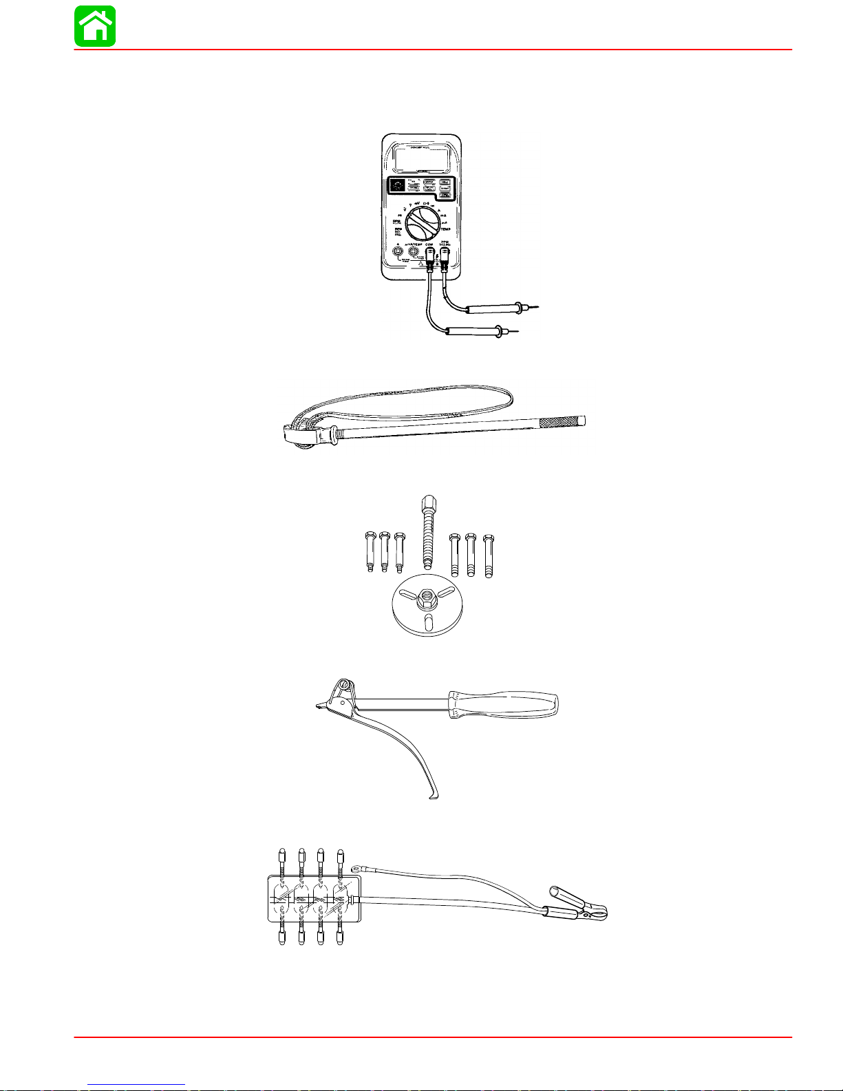
Special Tools
1. DMT 2000 Digital Tachometer Multi-meter P/N 91-854009A1
2. Flywheel Holder P/N 90-24937A1.
IGNITION
3. Flywheel Puller P/N 91-83164M.
4. Flywheel Holder 91-52344
5. Spark Gap Board 91-850439
54964
90-826883 R2 JUNE 1998 Page 2A-3
55117
Page 49
IGNITION
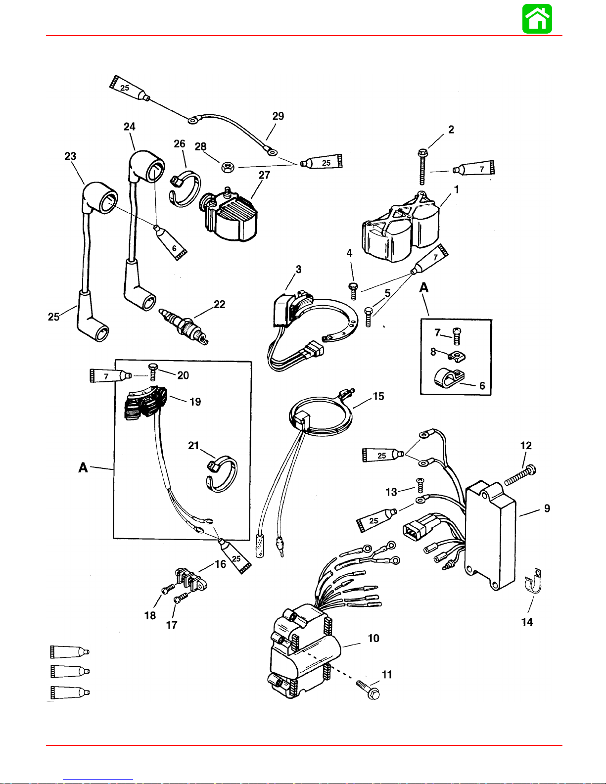
Ignition/Electrical Components
6
7
25
Dielectric Grease (92-823506--1)
Loctite 271 (92-809820)
Liquid Neoprene (92-25711--2)
A=ALTERNATOR VERSION ONLY
Page 2A-4 90-826883R2 JUNE 1998
Page 50

IGNITION
REF
.
9
1
0
2
2
Ignition/Electrical Components
TORQUE
QTY. DESCRIPTION lb. in. lb. ft. N·m
NO.
1 1 COVER--ignition coil
2 3 SCREW--ignition coil cover (M5x.8x55) 80 9.0
STATOR ASSEMBLY (20/25--USA-S/N-0G437999 & BELOW)
1
3
4 2 SCREW--stator attaching (M5x.8x25) 80 9.0
5 1 SCREW--stator attaching (M5x12) 80 9.0
6 1 CLIP
7 1 SCREW--clip to crankcase (#10-16x1/2 IN.) Drive Tight
8 1 C-WASHER-- clip screw
1 1 2 SCREW (M5 x 20)
12 3 SCREW (M5x.8x35 hex washer head) Drive Tight
13 1 SCREW--ground wire Drive Tight
14 1 CLIP
15 1 TRIGGER ASSEMBL Y
16 1 TERMINAL BLOCK
17 2
18 2 SCREW--terminal block (#10-16x3/8 IN.)
19 1 STATOR ASSEMBLY--auxiliary
20 3 SCREW (M5x.8x30 hex head) 80 9.0
21 AR STA-STRAP
23 1 HI-TENSION CABLE SET
24 1 HI-TENSION CABLE (Part of Ref. #22)
25 2 BOOT ASSEMBLY--spark plug
26 AR STA-STRAP
27 2 IGNITION COIL ASSEMBLY
28 4 NUT--coil terminal (1#10-32 Brass) 25 2.8
29 2 CABLE ASSEMBL Y (Black)
STATOR ASSEMBLY (20/25--USA-S/N-0G438000 & UP)
1
1 STATOR ASSEMBLY(JET 20)
1 SWITCH BOX (JET 20)(S# USA-0G590000 & UP)
1 SWITCH BOX (JET 20)(S#USA-0G589999 & BELOW)
SWITCH BOX (20/25--USA-S/N-0G437999 & BELOW)
1
SWITCH BOX (20/25--USA-S/N-0G438000 thru 0G589999)
1
SWITCH BOX (20/25--USA-S/N-0G590000 & UP)
1
SCREW--terminal block (#10-16x5/8 IN.) COMMERCIAL
2 SPARK PLUG (NGK #BP8H-N-10) 240 20 27.1
2 SPARK PLUG (NGK #BPZ8H-N-10) (CAN/BELG.) 20 27.1
BEL-S/N-9926999 & BELOW)
(BEL-S/N-9927000 thru 9973099)
(BEL-S/N-9973100 & UP)
(BEL-S/N-9926999 & BELOW)
(BEL-S/N-9927000 & UP)
90-826883 R2 JUNE 1998 Page 2A-5
Page 51

IGNITION
Ignition Description
The ignition system is an alternator driven capacitor discharge system. Major componentsof the ignitionsystemare theflywheel,stator,triggercoil,switch box,2ignitioncoils
and 2 spark plugs.
The flywheelhas permanent magnets mounted in both theouter rim andthe center hub.
TheBLACKstatorassembly ismountedbelowthe flywheelandhasalow speed(LS)and
ahigh speed(HS) capacitor chargingcoil. Lowspeedcoil providesprimaryvoltage tothe
switch box from idle to approximately 2500 RPM. The high speed coil provides primary
voltage from 2000 RPM to the maximum RPM the outboard is capable of achieving.
The RED stator assembly is mounted below the flywheel and has only one capacitor
charging coil.
Asthe flywheelrotates, the magnetsmounted inthe flywheelouterrim passthe charging
coils creating voltage. This voltage charges the capacitor located in the switch box.
As the flywheel continues to rotate, the magnets in the center hub pass the trigger coil
creatingAC voltage. Thisvoltageturns ononeofthe twoelectronic switches(SCR)in the
switchbox. Apositive voltagepulse turnson theSCR switchassociated withcylinder #1;
a negative voltage pulse turns on the SCR switch associated with cylinder #2.
The SCR switch discharges the stored capacitor voltage into the primary side of the respective ignition coil. The ignition coil multiplies this voltage to a value high enough to
jumpthesparkpluggap --32000 voltsforstandardcoils;40000voltsforhigh energy coils.
This sequence occurs once per engine revolution for each cylinder
Spark timingon electronicallyadvanced models iscontrolled internallyby the switchbox
with a fixed trigger.
Sparktimingonmechanicallyadvancedmodelsischanged(advanced/retarded) byrotat-
ingthe triggercoil which changesthe triggercoil positionin relationto themagnets in the
center hub of the flywheel.
The stop switch (or ignition switch) shorts the output of the stator to ground to stop the
engine on all models.
Page 2A-6 90-826883R2 JUNE 1998
Page 52

Electronic Spark Advance
20/25 OUTBOARDS SERIAL NUMBER:
USA 0G044027 THRU 0G437999
BELGIUM 09807909 THRU 09926999
20 JET OUTBOARDS
USA 0G044027 THRU 0G760299
BELGIUM 09807909 THRU 09016999
The spark timing is controlled by an electronic circuit within the engine switch box. The
trigger assembly is positioned for maximum advance. (Refer to Set-Up Timing/AdjustmentProcedure)Theelectronictiming featureoftheswitchboxretardsthetiming onstart
upand atidle RPM. Asthe engineRPM increasesthetiming willadvance. Maximumtiming will occur at approximately 2500 RPM.
Mechanical Spark Advance
20/25 OUTBOARDS SERIAL NUMBER:
USA 0G438000 AND ABOVE
BELGIUM 09927000 AND ABOVE
20 JET OUTBOARDS SERIAL NUMBER
USA 0G760300 AND ABOVE
BELGIUM 09017000 AND ABOVE
IGNITION
The spark timing is changed (advanced/retarded) by rotating the trigger coil, which
changes the trigger coil position in relation to the magnets in the center hub of the flywheel.
The stop switch (or ignition switch) shorts the output of the stator to ground to stop the
engine.
RPM Limiter
The20JETRED statorignitionmodulecontainsaRPMlimiter circuit whichinterruptsone
cylinder when RPM exceeds 6200 ± 100 RPM.
Ignition Component Description
Trigger Coil
A single woundcoil located under the flywheel. The trigger ischarged by the center hub
flywheel magnet and sends a pulse voltage to an (SCR) switch located in the ignition
switch
box.
a
a - Trigger Coil
ELECTRONIC SPARK ADVANCE
The trigger is mounted in a fixed timing position.
90-826883 R2 JUNE 1998 Page 2A-7
52642
Page 53

IGNITION
MECHANICAL SPARK ADVANCE
Spark timing ischanged (advanced/retarded) by rotating the trigger coil, which changes
the trigger coil position in relation to the magnets in the center hub of the flywheel.
Stator
The ignition stator located under the flywheel contains two stator windings. One low
speed winding and one high speed winding.
As the outer flywheel magnets pass the stator windings, a current is produced that
charges a capacitor in the ignition switch box.
Electronic Spark Advance Stator
b
a
Flywheel
52642
a - Low Speed Winding
b - High Speed Winding
e
b
b
c
a
a
e
57129
a - Center Hub Magnet
b - Outer Magnet
c - BLACK Stator Flywheel (2 Magnets)
d - RED Stator Flywheel (4 Magnets)
e - Spacers
The flywheel assembly (BLACK stator) contains two outer magnets (8 Pole) (4 Pulse),
and one center hub magnet. The outer magnets are needed for battery charge coil and
ignition charge coils. The inner hub magnet is for trigger coil.
d
Theflywheel assembly (REDstator)containsfour outermagnets(10Pole) (5 Pulse),and
onecenterhubmagnet.Theoutermagnetsareneededforbatterychargecoilandignition
charge coils. The inner hub magnet is for trigger coil.
NOTE: Commercial andservice flywheels will have 2 additional spacersand a retaining
ring used only with the RED stator.
Page 2A-8 90-826883R2 JUNE 1998
Page 54

Ignition Coil
The primary (+) side of the ignition coil receives voltage discharged from a capacitor in
theignition switchbox. The voltageis multipliedbythe coiluntil itcanjump thespark plug
gap. Ignition coil maximum output approximately 35000 volts.
b
a - Positive (+) Primary Terminal
b - Negative Terminal
Ignition Switch Box
ELECTRONIC SPARK ADVANCE (BLACK STATOR)
Theignitionswitchbox receivesanACcurrentfrom the lowandhighspeed statorassembly. Thiscurrentisrectifiedand changed toaDCcurrentwhere itwillbestoredintheinternalcapacitor.Avoltagepulsefromthe triggerassembly(infiring order) turnsonarespectiveSCR switchwhich discharges thecapacitor storedvoltageand sendsitto theignition
coil.
IGNITION
a
52642
The switch box contains an electrical circuit that controls the ignition spark timing. The
switch box senses the engine R.P.M. by counting trigger pulses and adjusts the engine
timing accordingly.
No idle timing adjustment is required. Refer to the Timing/Synchronizing/Adjusting section of this manual.
a
b
c
d
e
f
g
h
i
j
a - #1 Coil Primary Lead (Green/Yellow)
b - #2 Coil Primary Lead (Green/White)
c - Ground Lead
d - Stator Connector
e - Stator Lead (RED) High Speed
f - Stator Ground Lead (BLACK)
g - Stator Lead (Blue) Low Speed
h - Engine Stop Lead (BLACK/YELLOW)
i - Trigger Lead (BROWN/WHITE)
j - Trigger Lead (BROWN/YELLOW)
52642
90-826883 R2 JUNE 1998 Page 2A-9
Page 55
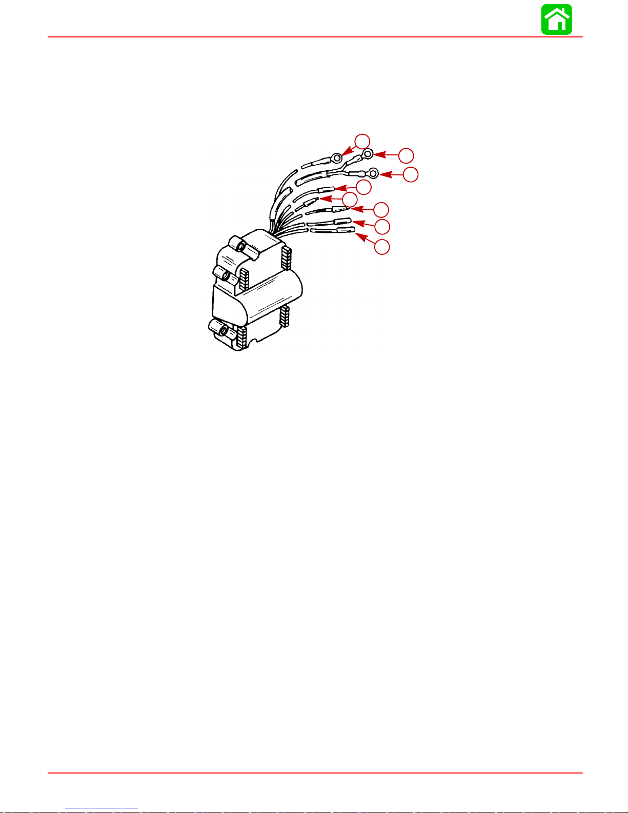
IGNITION
MECHANICAL SPARK ADVANCE (BLACK STATOR)
Theignitionswitchbox receivesanACcurrentfrom the lowandhighspeed statorassembly. Thiscurrentisrectifiedand changed toaDCcurrentwhere itwillbestoredintheinternalcapacitor.Avoltagepulsefromthe triggerassembly(infiring order) turnsonarespectiveSCR switchwhich discharges thecapacitor storedvoltageand sendsitto theignition
coil.
c
b
a
d
e
f
g
h
a - #1 Coil Primary Lead (Green/Yellow)
b - #2 Coil Primary Lead (Green/White)
c - Ground Lead
d - Engine Stop Lead (BLACK/YELLOW)
e - Trigger Lead (BROWN/YELLOW)
f - Stator Lead (BLACK/WHITE) High Speed
g - T rigger Lead (BROWN/WHITE)
h - Stator Lead(BLACK/YELLOW) Low Speed
MECHANICAL AND ELECTRONIC SPARK ADVANCE (RED STATOR)
The mechanical and electronic spark advance mechanism/circuitry operate the same
withthe REDstator as theydo withtheBLACK stator.Theonly differenceisthat theRED
stator has only 1 charging coil whereas the BLACK stator has 2 charging coils; 1 high
speed coil and 1 low speed coil.
Page 2A-10 90-826883R2 JUNE 1998
Page 56

Electronic Spark Advance
IGNITION
30
25
20
15
Set-Up Timing
28° B.T.D.C.
@3000 ± 200
RPM
5500 RPM
25° B.T.D.C.
5800 R.P.M.
6200 RPM
15° B.T.D.C.
10
5
750 ± 50 R.P.M.
Approx. 3-5° B.T.D.C.
0
1000 2000 3000 4000
Engine Speed - RPM
5000
6000 7000
90-826883 R2 JUNE 1998 Page 2A-11
Page 57

IGNITION
Ignition Test Procedures
Direct Voltage Adapter (DVA)
DANGER -- HIGHVOLTAGE/SHOCKHAZARD! Do not touch ignitioncomponents
and/or metal test probes while engine is running and/or being “cranked”. STAY
CLEAR OF SPARK PLUG LEADS. To assure personal safety, each individual
spark plug lead should be grounded to engine.
When testing or servicing the ignition system, high voltage is present. DO NOT
TOUCH OR DISCONNECT any ignition parts while engine is running, while key
switch is on or while battery cables are connected.
Failure to comply with the following items may result in damage to the ignition
system.
1. DO NOT reverse battery cable connections. The battery negative cable is (-)
ground.
WARNING
WARNING
CAUTION
2. DO NOT“spark” battery terminals with battery cable connectionsto checkpo-
larity.
3. DO NOT disconnect battery cables while engine is running.
4. DO NOT crank engine with CDI or Ignition Coils not grounded.
CAUTION
To protect against meter and/or component damage, observe the following precautions:
· 400 VDC* test position (or higher) MUST BE used for all tests.
· INSURE the Positive (+) lead/terminal of DVA is connected to the Positive (+) re-
ceptacle of meter.
· DO NOT CHANGE meter selector switch position while engine is running and/or
being “cranked”.
· ALL COMPONENTS MUST BE GROUNDED during tests. Running or “cranking”
engine with CDI or Ignition Coils ungrounded may damage components.
* If using a meter with a built-in DVA, the DVA/400or DVA/500VDC test position should
be used.
NOTE: Test leads are not supplied with the Direct Voltage Adapter. Use test leads
supplied with multi meter.
Test proceduresand specificationsare providedfor checking primary ignition voltage
while the engine is running and/or being “cranked” with all harnesses connected.
Page 2A-12 90-826883R2 JUNE 1998
Page 58

Ignition Troubleshooting
DANGER -HIGHVOLTAGE/SHOCK HAZARD! Do nottouch ignitioncomponents
and/or metal test probes while engine is running and/or being “cranked”. STAY
CLEAR OF SPARK PLUG LEADS. To assure personal safety, each individual
spark plug lead should be grounded to engine.
When testing or servicing the ignition system, high voltage is present. DO NOT
TOUCH OR DISCONNECT any ignition parts while engine is running.
Ignition Diagnostic Procedures
TROUBLESHOOTINGTIP:Withenginerunning,useinductivetiminglighttocheckspark
advanceof eachcylinderas throttleisopened andclosed.If timingadvancesand retards
smoothly on each cylinder, ignition system is MOST LIKELY functioning properly
IMPORTANT: If outboard appears to have an ignition system failure, it is recommended that before beginning in-depth troubleshooting:
IGNITION
WARNING
WARNING
a. Ensure that the engine is mechanically sound condition. (Fuel System, Cylinder
Compression etc.).
b. Check all engine ground leads for loose or corroded connections.
c. Disconnect andreconnect ignitionharnessconnectors toverify propercontinuity.
PROBLEM CORRECTION
1. No Spark or Weak Spark on Both Cylinders No Spark -- Trigger, Stator, Ignition Switch Box or
Bad Ground Connection from Switch Box to Block
Weak Spark -- Stator
2. No Spark or Weak Spark on 1 Cylinder Ignition Switch Box or Coil
3. Timing Fluctuates -- Note: It is normal for timing
to fluctuate 2°-3° @ Idle.
-- If engine RPM exceeds
5800, switch box will retard
timing from 25° BTDC to 15°
BTDC
--If engine RPM drops below
600, idle stabilizer in switch
box will advance timing to
as
high as 10° BTDC @ crank
ing speed of 300 RPM.
4. Timing will not Advance -- Note: If timing will not
advance on only
1 cylinder, check wir-
ing for shorted trigger wire
Shorted Trigger Wire or Ignition Switch Box
Defective Switch Box
5. Engine Misfires @ High RPM Defective Coil
90-826883 R2 JUNE 1998 Page 2A-13
Defective Switch Box
Page 59

IGNITION
6. Engine Hard to Start when Cold Defective Trigger Assembly
Defective Ignition Switch Box
7. Engine Misfires @ Low RPM but Runs Smooth
@ High RPM
Defective Harness or (loose connections)
Defective Switch Box
Defective Stator
8. Engine Starts Hard when Hot Defective Switch Box or Trigger
9. Engine Occasionally Misfires Replace Standard Spark Plug with Inductor Plug
Bad Ground Connection from Switch Box to Block
Page 2A-14 90-826883R2 JUNE 1998
Page 60

Ignition Troubleshooting
Electronic Spark Advance
DANGER -- HIGH VOLTAGE/SHOCK HAZARD! Do not touch ignition components and/or
metal test probes while engine is running and/or being “cranked”. STAY CLEAR OF
SPARK PLUG LEADS. To assure personal safety, each individual spark plug lead should
be grounded to engine.
When testing or servicing the ignition system, high voltage is present. DO NOT TOUCH
OR DISCONNECT any ignition parts while engine is running, while key switch is on.
Tool: Multimeter/DVA Tester 91-99750A1
IGNITION
WARNING
WARNING
Component
Test
Test 1
Test 2
Test 3
Test 4
Coil
Primary
Sw. Box -
Stop Circuit
Stator -
Low Speed
Stator -
High Speed
*If usinga meterthat requires aDVAadapter,place selectorswitch to the400 VDCposition.
(1)Readings may vary at cranking speed or at idle.
(2)Back probe the electrical connector in order to make connection.
Tested Part Multimeter
Test 5 Stator
Test 6 Trigger
Selector
Sw.
Position
400 DVA*
400 DVA*
400 DVA*
400 DVA*
DVA Lead
Red
Coil (+)
Terminal
Black/Yellow
Sw. Box Terminal
Blue Sw. (2)
Box Terminal
Red Sw. (2)
Box Terminal
DVA Lead
Black
Coil (--)
Terminal
Ground 220-320 300-350
Ground 220-320 300-350
Ground 30-220 200-280
Multimeter Ohm Checks
Connected To: Meter Scale Meter Reading
Wires
RED
BLACK
RED
BLACK
RED
BLACK
RED
BLACK
RED
BLACK
BLUE
BLACK
RED
BLUE
BROWN/WHITE
BROWN/YEL-
LOW
Voltage
Reading
(1)
@300-3000
RPM
160-250 (1) 200-280
R x 1 W 100 - 180
R x 100 W 29 - 35
R x 100 W 28 - 34
R x 100 W 6.5 - 8.5
Voltage
Reading
@ 3000-4000
RPM
90-826883 R2 JUNE 1998 Page 2A-15
Page 61

IGNITION
Test7IgnitionCoil
s
RED
Test 7 Ignition Coils
(“+”) wire discon-
nected)
BLACK
RED
BLACK
NOTE: Copper isan excellentconductor,however resistance may notably varybetween
low and high temperature.Therefore, reasonable differences can be accepted between
resistance readings and specifications.
The above readings are for a cold (room temperature) engine. Resistance will increase
if the engine is warm.
Ignition Troubleshooting
Mechanical Spark Advance
TOOL : MULTIMETER/DVA TESTER 91-99750
Tested Part
Stator (BLACK/
YELLOW and
BLACK/WHITE
wires disconnected from switch
boxes)
Trigger (BROWN/
YELLOW and
BROWN wires disconnected from
switch boxes)
Multimeter
Wires
RED
BLACK
RED
BLACK
RED
BLACK
RED
BLACK
(+) Terminal
(--) Terminal
Spark Plug Tower
(+) Terminal
Connected To
BLACK/WHITE
GROUND
BLACK/YELLOW
GROUND
BLACK/YELLOW
BLACK/WHITE
BROWN/YELLOW
BROWN
R x 1 W 0
R x 100 W 8.5 - 12
Scale
R x 1 120 - 180
R x 100
R x 100
R x 100 6.5 - 8.5
Resistance
(ohms)
32 - 38
31 - 37
Tested Part
Ignition Coils
(all wires disconnected)
Tested Part
Switch Box
Primary Coil
Switch Box
Stop Circuit
Stator Low
Speed
Stator High
Speed
Multimeter
Multimeter
Wires
RED
BLACK
RED
BLACK
RED
BLACK
RED
BLACK
RED
BLACK
Connected To
-- Terminal
+ Terminal
BLACK/YELLOW
BLACK/WHITE
Spark Plug Tower
GROUND
GROUND
Connected To
+ Terminal
-- Terminal
-- Terminal
Selector
Position
400 VDC 125 -260
400 VDC
400 VDC 10 - 75 50 - 300
Scale
R x 1
R x 1000
Reading At
300 - 1000 RPM
150 - 300
Resistance
(ohms)
0.02 - 0.04
8 - 11
Reading At
1000 - 4000 RPM
200 - 360
250 - 360
Page 2A-16 90-826883R2 JUNE 1998
Page 62

Ignition Troubleshooting (RED Stator)
TOOL : MULTIMETER/DVA TESTER 91-99750
IGNITION
Tested Part
Stator (GREEN/
WHITE and
WHITE/GREEN
wires disconnected
from switch boxes)
Trigger (BROWN/
YELLOW and
BROWN/WHITE
wires disconnected
from switch boxes)
Tested Part
Ignition Coils
(all wires disconnected)
Multimeter
Wires
RED
BLACK
RED
BLACK
Multimeter
RED
BLACK
RED
BLACK
Connected To
GREEN/WHITE
WHITE/GREEN
BROWN/YELLOW
BROWN/WHITE
Connected To
+ Terminal
-- Terminal
Spark Plug Tower
-- Terminal
Scale
R x 1 370 - 445
R x 100
Scale
R x 1
R x 1000
Resistance
(ohms)
6.5 - 8.5
Resistance
(ohms)
0.02 - 0.04
8 - 11
Tested Part
Switch Box
Primary Coil
Switch Box
Stop Circuit
Stator V oltage
Multimeter
Wires
RED
BLACK
RED
BLACK
RED
BLACK GROUND
RED
BLACK GROUND
Connected To
-- Terminal
+ Terminal
BLACK/YELLOW
GROUND
GREEN/WHITE
WHITE/GREEN
Selector
Position
400 VDC
400 VDC
400 VDC 150 - 330 250 - 330
400 VDC 150 - 330 250 - 330
Reading At
300 - 1000 RPM
125 - 320
150 - 330
Reading At
1000 - 4000 RPM
200 - 320
250 - 330
NOTE: Copper is an excellent conductor, but resistance may notably vary between low
and high temperature. Therefore, reasonable differences can be accepted between resistance readings and specifications.
90-826883 R2 JUNE 1998 Page 2A-17
Page 63

Section 2B - Battery Charging and Starting Systems
Table of Contents
BATTERY CHARGING AND STARTING SYSTEMS
ELECTRICAL
2
Specifications 2B-1. . . . . . . . . . . . . . . . . . . . . . . . . . . . . . .
Electric Start Components 2B-2. . . . . . . . . . . . . . . . . . . .
Battery 2B-4. . . . . . . . . . . . . . . . . . . . . . . . . . . . . . . . . . . . .
Precautions 2B-4. . . . . . . . . . . . . . . . . . . . . . . . . . . . . .
Recommended Battery 2B-4.. . . . . . . . . . . . . . . . . . .
Operating Engine Without Battery 2B-4. .. .. .. .. ..
Specific Gravity Readings 2B-4. . . . . . . . . . . . . . . . . .
Electrolyte Level 2B-5.. .. .. .. .. .. .. .. .. .. .. .. ..
Charging A Discharged Battery 2B-6. . . . . . . . . . . . .
Winter Storage of Batteries 2B-6. .. .. .. .. .. .. .. .
Voltage Regulator Test 2B-7.. . . . . . . . . . . . . . . . . . . . . .
Lamps Burn Out When Engine RPM is
Increased 2B-7. . . . . . . . . . . . . . . . . . . . . . . . . . . . . . .
Lamps Burn Dim at Wide-Open-Throttle 2B-7. . . . .
Battery Charging System 2B-7. . . . . . . . . . . . . . . . . . . . .
Description 2B-7. . . . . . . . . . . . . . . . . . . . . . . . . . . . . .
Alternator Amperes Output 2B-8. .. .. .. .. .. .. .. ..
Battery Charging System
Troubleshooting 2B-9. . . . . . . . . . . . . . . . . . . . . . . . . .
Alternator Test 2B-9. . . . . . . . . . . . . . . . . . . . . . . . . . .
Rectifier Test 2B-10. . . . . . . . . . . . . . . . . . . . . . . . . . . .
Starting System 2B-11.. . . . . . . . . . . . . . . . . . . . . . . . . . .
Starter Motor Amperes Draw 2B-1 1.. . . . . . . . . . . . .
Starting System Components 2B-11. . . . . . . . . . . . .
Description 2B-1 1.. . . . . . . . . . . . . . . . . . . . . . . . . . . .
Troubleshooting the Starting Circuit 2B-11. . . . . . . .
Commander 2000 Key Switch Test 2B-14. . . . . . . . .
Emergency Stop Switch
(Lanyard Type) 2B-15. .. .. .. .. .. .. .. .. .. .. .. .. .
Push Button Stop Switch 2B-15. . . . . . . . . . . . . . . . .
Starter Motor 2B-16. . . . . . . . . . . . . . . . . . . . . . . . . . . . . .
Disassembly 2B-16. . . . . . . . . . . . . . . . . . . . . . . . . . . .
Cleaning and Inspection 2B-17. . . . . . . . . . . . . . . . . .
Testing Motor Armature 2B-18. . . . . . . . . . . . . . . . . . .
Starter Motor Reassembly 2B-19.. . . . . . . . . . . . . . .
Starter Solenoid Test 2B-21. .. .. .. .. .. .. .. .. .. ..
Flywheel Ring Gear 2B-22. . . . . . . . . . . . . . . . . . . . . . . . .
Installation 2B-22.. .. .. .. .. .. .. .. .. .. .. .. .. .. ..
Neutral Start Switch (Electric Start Tiller
Handle Shift Models) 2B-23. . . . . . . . . . . . . . . . . . . . . . . .
Tiller Handle Start Button 2B-24. .. .. .. .. .. .. .. .. .. .
Choke Solenoid 2B-25.. .. .. .. .. .. .. .. .. .. .. .. .. ..
Installation 2B-25.. .. .. .. .. .. .. .. .. .. .. .. .. .. ..
Battery Cables/Engine Wiring Harness
(Remote Electric Start Models) 2B-26. . . . . . . . . . . . . . .
Battery Cables (Tiller Handle Push Button
Electric Start Models) 2B-29. . . . . . . . . . . . . . . . . . . . . . .
Installation 2B-29.. .. .. .. .. .. .. .. .. .. .. .. .. .. ..
Plug Harness (Battery Charging Kit) 2B-31. . . . . . . . . . .
Installation 2B-31.. .. .. .. .. .. .. .. .. .. .. .. .. .. ..
Emergency Stop Switch (Lanyard Type) 2B-31. . . . . . .
Installation 2B-31.. .. .. .. .. .. .. .. .. .. .. .. .. .. ..
B
Specifications
BATTERY Battery Rating 465 Marine Cranking Amps (MCA)
or 350 Cold Cranking Amps (CCA)
CHARGING
SYSTEM
STARTING
SYSTEM
Alternator Output
BLACK Stator - 2 Magnet Flywheel
RED Stator - 4 Magnet Flywheel
Manual Start
Electric Start
Ampere Draw (Under Load)
(8 Pole -- 4 Pulse)
(10 Pole -- 5 Pulse))
(No Load)
4 Amp. (48 Watt)
@ 6000 RPM
6 amp (72 Watt)
@ 6000 RPM
Recoil
12 Volt
55 amperes
15 Amperes
90-826883R2 JUNE 1998 Page 2B-1
Page 64
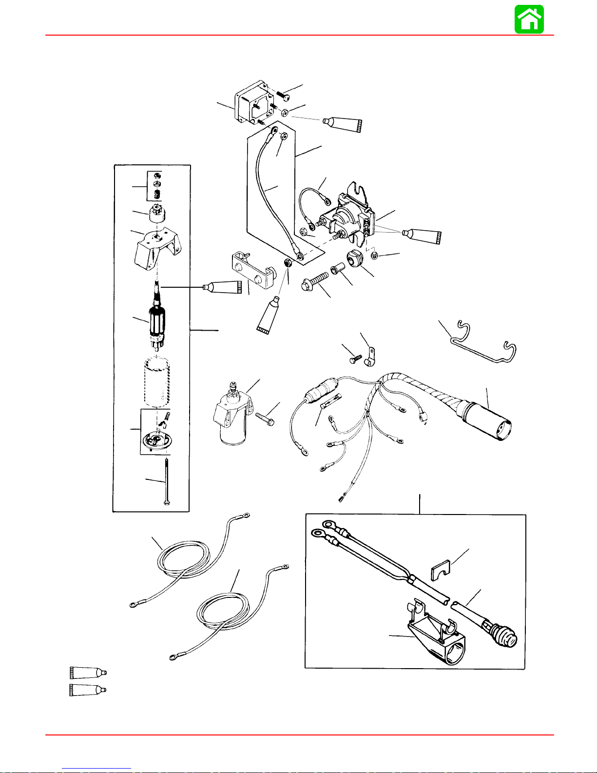
BATTERY CHARGING AND STARTING SYSTEMS
Electric Start Components
2
26
25
24
23
1
3
25
A
14
B
4
5
14
13
25
20
27
12
9
6
25
11
7
8
10
15
16
17
18
22
21
32
31
14
25
A=LOCAL ELECTRIC ONLY B=SERVICE ONLY
2 Cycle Outboard Oil (92-13249A24)
Liquid Neoprene (92-25711--2)
19
A
28
29
30
Page 2B-2 90-826883R2 JUNE 1998
Page 65

BATTERY CHARGING AND STARTING SYSTEMS
REF
.
Electric Start Components
TORQUE
QTY. DESCRIPTION lb. in. lb. ft. N·m
NO.
1 1 RECTIFIER
2 2 SCREW (#10-16x5/8 IN.) Drive Tight
3 2 NUT (#10-32 Brass) 25 2.8
4 1 NUT (#10-32 Brass) 25 2.8
5 1 CABLE ASSEMBLY (Red)
6 1 STARTER SOLENOID ASSEMBLY
7 2 BUSHING
8 2 GROMMET
9 1 WIRE ASSEMBLY--yellow
10 2 SCREW (M6x1x25 hex head cap) 40 4.5
1 1 2 NUT (#8-32 Brass) 25 2.8
12 1 NUT (1/4-20) 30 3.4
13 1 INSULATOR--solenoid
14 1 NUT (1/4-20) 30 3.4
15 1 RETAINER--harness connector
16 1 J-CLIP
17 1 SCREW (M6x30 hex head cap) 140 12.0 15.8
18 1 WIRING HARNESS ASSEMBLY--engine
19 1 FUSE
20 1 STARTER MOTOR ASSEMBLY
21 1 THRU BOLT
22 1 END CAP (W/BRUSHES)
23 1 ARMATURE
24 1 DRIVE CAP
25 1 DRIVE
26 1 DRIVE KIT
27 2 SCREW (M8x1.25x55 hex washer) 220 18.0 24.8
28 1 CLIP
29 1 START SWITCH ASSEMBLY
30 1 HOUSING--switch
31 1 BATTERY WIRE ASSEMBLY--black
32 1 BATTERY WIRE ASSEMBLY--red
90-826883R2 JUNE 1998 Page 2B-3
Page 66
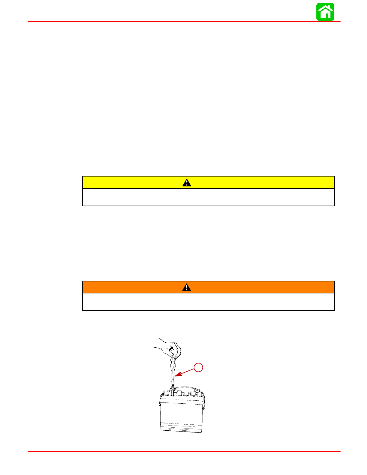
BATTERY CHARGING AND STARTING SYSTEMS
Battery
Precautions
Whenchargingbatteries,anexplosivegas mixtureformsineachcell.Aportionof this gas
escapes thruholes in vent plugs and may form an explosive atmosphere around battery
ifventilation ispoor.Thisexplosive gasmay remain inor aroundbatteryfor severalhours
after ithas been charged. Sparksor flames can ignite this gas and cause aninternal explosion which may shatter the battery.
The following precautions should be observed to prevent an explosion.
1. DO NOT smoke near batteries being charged or which have been charged very recently.
2. DO NOT break live circuits at terminals of batteries because a spark usually occurs
at the point where a live circuit is broken. Always be careful when connecting or disconnectingcableclampsonchargers.Poorconnectionsarea common cause ofelectrical arcs which cause explosions.
3. DO NOT reverse polarity of battery cables on battery terminals.
CAUTION
If battery acid comes into contact with skin or eyes, wash skin immediately with
a mild soap. Flush eyes with water immediately and see a doctor.
Recommended Battery
A 12volt battery with a “MarineCranking Amperage” rating minimumof 465 amperes or
or a “Cold Cranking Amperage” of 400.
Operating Engine Without Battery
If desired (or in an emergency), engines equipped with an alternator can be started and
operatedwithout abattery (either disconnectedor removed)if “WARNING”, below, isfol-
lowed.
Before operating engine with battery leads disconnected from battery, disconnectstator leads(Yellow)fromrectifier.Insulate (tape)stator lead ringterminals.
Specific Gravity Readings
Use a hydrometer to measure specific gravity of electrolyte in each cell.
WARNING
a - Hydrometer
Page 2B-4 90-826883R2 JUNE 1998
a
22532
Page 67

BATTERY CHARGING AND STARTING SYSTEMS
Hydrometermeasurespercentageofsulfuricacidinbatteryelectrolyteintermsofspecific
gravity. Asabattery dropsfromacharged toadischarged condition, acidleavesthesolution and chemically combines with the plates, causing a decrease in specific gravity of
electrolyte. An indication of concentration of electrolyte is obtained with a hydrometer.
When using a hydrometer, observe the following points:
1. Hydrometer must be clean (inside and out) to insure an accurate reading.
2. Never take hydrometer readings immediately after water has been added. Water
mustbe thoroughlymixedwith electrolytebycharging foratleast 15minutesat arate
high enough to cause vigorous gassing.
3. If hydrometerhas built-inthermometer,draw liquid inseveral timesto ensure correct
temperature before taking reading.
4. Holdhydrometer vertically anddrawin justenoughliquidfrom batterycellsothat float
is free-floating. Holdhydrometer at eye level so thatfloat is vertical and free of outer
tube, then take reading at surface of liquid. Disregard curvature where liquid rises
against float stem due to capillary action.
5. Avoid dropping electrolyte on boat or clothing, as it is extremely corrosive. Wash off
immediately with baking soda solution.
Specificgravity ofelectrolyte varies notonly withpercentageof acidin liquidbutalso with
temperature.As temperature drops, electrolyte contracts, so that specific gravity increases.Unlessthesevariationsinspecific gravityaretakenintoaccount,specificgravity
obtained byhydrometer maynot give atrue indicationof concentrationof acid in electrolyte.
A fully charged battery will have a specific gravity reading of approximately 1.270 at an
electrolyte temperatureof 80°F (27° C). Ifelectrolyte temperature is above or below80°
F, additions or subtractions must be made in order to obtain a hydrometer reading correctedto80°Fstandard.Forevery10°F(3.3°C)above80°F,add4specificgravitypoints
(.004) tohydrometer reading. Example:A hydrometer readingof 1.260 at110°F (43° C)
would be 1.272 corrected to 80° F, indicating a fully charged battery.
Forevery10°below80°F,subtract4points(.004)fromthereading.Example:Ahydrometerreadingof1.272at0°F(-18°C)wouldbe1.240correctedto 80° F,indicatingapartially
charged battery.
SPECIFIC GRAVITY CELL COMPARISON TEST
This test may be used when an instrumental tester is not available. To perform this test,
measure specific gravityof each cell, regardless of state of charge, and interpretresults
as follows:If specific gravityreadings show a difference betweenhighest and lowestcell
of .050 (50 points) or more, battery is defective and should be replaced.
Electrolyte Level
Check electrolyte level in battery regularly. A battery in use in hot weather should be
checked morefrequently becauseof morerapid loss ofwater.If electrolytelevel isfound
to below, thendistilled watershould be added to each celluntil liquid level rises approximately 3/16” (4.8mm) over plate. DO NOT OVERFILL, because this will cause loss of
electrolyte and result in poor performance, short life and excessive corrosion.
During service, only distilled water should be added to the battery, not electrolyte.
90-826883R2 JUNE 1998 Page 2B-5
CAUTION
Page 68

BATTERY CHARGING AND STARTING SYSTEMS
Charging A Discharged Battery
The following basic rules apply to any battery charging situation:
1. Any batterymay becharged at anyrate (inamperes) aslong asspilling of electrolyte
(fromviolent gassing) doesnotoccur andaslongas electrolytetemperaturedoesnot
exceed 125° F (52° C). If spewing of electrolyte occurs, or if electrolyte temperature
exceeds 125°F, charging rate(in amperes)must be reduced or temporarilyhalted to
avoid damage to the battery.
2. Batteryisfullychargedwhen,overa2-hourperiodatalowchargingrate(inamperes),
all cells are gassing freely (not spewing liquid electrolyte), and no change in specific
gravity occurs. Full charge specific gravity is 1.260-1.275, corrected for electrolyte
temperature with electrolyte level at 3/16” (4.8mm) over plate. For most satisfactory
charging, lower charging rates in amperes are recommended.
3. If, after prolonged charging, specific gravity of at least 1.230 on all cells cannot be
reached, battery is not in optimum condition and will not provide optimum performance;however,it maycontinueto provideadditional service, ifit hasperformedsatisfactorily in the past.
4. To checkbattery voltagewhile crankingengine withelectric startermotor,place RED
(+) lead of tester on POSITIVE (+) battery terminal and BLACK (--) lead of tester on
NEGATIVE (--) batteryterminal. Ifthe voltagedrops below9-1/2 voltswhile cranking,
the battery is weak and should be recharged or replaced.
Winter Storage of Batteries
Battery companies arenot responsible for battery damage, either in winter storage or in
dealer stock, if the following instructions are not observed:
1. Remove battery fromits installation as soon as possible and removeall grease, sulfate anddirt from top surface by running waterover top ofbattery.Be sure, however,
thatventcapsare tightbeforehandandblowoffallexcess waterthoroughlywithcompressed air. Check water level, making sure that plates are covered.
2. Whenadding distilledwater tobattery,be extremelycareful notto fill more than 3/16”
(4.8mm) over plate inside battery. Battery solution or electrolyte expands from heat
caused by charging. Overfilling battery will cause electrolyte to overflow (if filled beyond 3/16” over plate).
3. Greaseterminal boltswell with Quicksilver2-4-C MarineLubricant, andstore battery
in COOL-DRY place. Remove battery from storage every 30-45 days, check water
level (add water if necessary), and put on charge for 5 or 6 hours at 6 amperes. DO
NOT FAST CHARGE.
4. If specific gravity drops below 1.240, check battery for reason, and then recharge.
When gravity reaches 1.260, discontinue charging. To check specific gravity, use a
hydrometer, which can be purchased locally.
5. Repeatpreceding chargingprocedure every30-45days, aslong asbattery isinstorage. Whenready toplace battery backin service,remove excessgrease fromterminals(a smallamount is desirableon terminalsat alltimes), rechargeagain asnecessary and re-install battery .
Hydrogen and oxygen gases are produced during normal battery operation or
charging.Sparksor flame cancausethismixturetoignite and explode, iftheyare
brought near the battery. Sulfuric acid in battery can cause serious burns, if
spilled on skin or in eyes. Flush or wash away immediately with clear water.
Page 2B-6 90-826883R2 JUNE 1998
WARNING
Page 69

Voltage Regulator Test
Lamps Burn Out When Engine RPM is Increased
The voltage regulator is defective. Replace regulator.
Lamps Burn Dim at Wide-Open-Throttle
1. Run engine at mid-range (approximately 3000 RPM) with 3 number 94 lamps connected to voltage regulator output leads. Note lamp brightness.
2. Disconnect the leads at one terminal of regulator. Connect the leads together using
a screw and nut. Isolate (tape) connection.
3. Run engine at mid-range (approximately 3000 RPM) and note lamp brightness. If
lamps areconsiderably brighterthan with leadsconnected toregulator,the regulator
is defective. If lamps are NOT considerably brighter, check the alternator (refer to “
Alternator Test” , following.
Battery Charging System
Description
BATTERY CHARGING AND STARTING SYSTEMS
Thebatterychargingsystemcomponentsarethealternator,rectifierandbattery.Alternating current(generated in alternator coils) flows to therectifier which changesAC current
to direct current (DC) for charging the battery.
a
c
b
a - Alternator
b - Rectifier
c - Battery
The charging system may be damaged by:
a. Reversed battery cables.
b. Running the engine with battery cables disconnected and alternator leads con-
nected to rectifier.
c. An open circuit -- such as a broken wire or loose connection.
90-826883R2 JUNE 1998 Page 2B-7
Page 70

BATTERY CHARGING AND STARTING SYSTEMS
Alternator Amperes Output
Amperage output can be measured by installing a 10 ampere (minimum) amp meter in
series between the rectifier and the battery or by clamping an inductive type amp meter
(10 amp minimum) over the RED output lead from the rectifier to the battery.
BLACK Stator (2 Magnet Flywheel)
RPM AMPERES (Approximate)
Idle 0
1000 0
2000 .5
3000 2.2
4000 3.1
5000 3.8
6000 4.0
RED Stator (4 Magnet Flywheel)
RPM AMPERES (Approximate)
Idle 0
1000 0.8
2000 4.1
3000 5.3
4000 5.8
5000 6.1
6000 6.3
Page 2B-8 90-826883R2 JUNE 1998
Page 71

Battery Charging System
Troubleshooting
A fault in the battery charging system usually will cause the battery to become under charged. Check battery electrolyte level, and charge battery. See “Electrolyte Level”,
and “Charging a Discharged Battery”.
If battery will NOT accept a satisfactory charge, replace battery.
Ifbatteryacceptsasatisfactorycharge,determinethecauseofthechargingsystemprob-
lem as follows.
1. Checkfor correctbattery polarity [REDcable toPOSITIVE(+) batteryterminal].If polarity was incorrect, check for damaged rectifier. See “RECTIFIER TEST”.
2. Check for loose or corroded battery connections.
3. Visuallyinspectwiringbetweenstatorandbatteryforcuts,chafing;anddisconnected,
loose or corroded connection.
4. Excessiveelectrical load(from too manyaccessories) willcause batteryto rundown.
If visual inspection determines that battery connections and wiring are OK, perform the
following stator and rectifier tests.
Alternator Test
BATTERY CHARGING AND STARTING SYSTEMS
*NOTE: Alternator can be tested without removing from engine. DC resistance of these
windings generally is less than 1 ohm. A reading that resembles a short is acceptable.
1. Disconnect GRAY and YELLOW alternator leads from terminals on either rectifier,
voltage regulator or isolator block.
2. Use an ohmmeter and perform tests as shown in following chart.
3. If meter readings are other than specified, replace alternator assembly.
Test Leads Resistance Scale
RED to YELLOW
BLACK to GRAY
RED to either GRAY or YELLOW
BLACK to GROUND NO CONTINUITY R x 1000
0.65 R x 1
90-826883R2 JUNE 1998 Page 2B-9
Page 72

BATTERY CHARGING AND STARTING SYSTEMS
Rectifier Test
Disconnect battery leads from battery before testing rectifier.
*NOTE: Rectifier can be tested without removing from engine.
WARNING
Rectifier Test (continued)
Continuity Indicated
Connect BLACK meter lead to ground, RED
lead alternately to terminals “a” and “c”.
a
d
b
e
Connect RED meter lead to ground, BLACK lead
alternately to terminals “a” and “c”.
c
f
07300
No Continuity Indicated
Connect BLACK meter lead to ground, RED
lead alternately to terminals “a” and “c”.
No Continuity Indicated
Connect BLACK meter lead to terminal “b”,
RED lead alternately to terminals “a” and “c”.
Continuity Indicated
Connect RED meter lead to terminal “b”, BLACK lead alternately to
terminals “a” and “c”.
No Continuity Indicated.
Rectifier tests O.K.
Continuity Indicated.
Replace Rectifier.
Continuity Indicated.
Replace Rectifier.
No Continuity Indicated.
Replace Rectifier.
No Continuity Indicated.
Replace Rectifier.
Continuity Indicated.
Replace Rectifier.
Continuity Indicated
Connect BLACK meter lead to terminal “b”,
RED lead alternately to terminals “a” and “c”.
Connect RED meter lead to terminal “b”, BLACK lead alternately to
terminals “a” and “c”.
No Continuity Indicated.
Replace Rectifier.
No Continuity Indicated
Continuity Indicated.
Rectifier Tests O.K.
Page 2B-10 90-826883R2 JUNE 1998
Page 73

Starting System
STARTER MOTOR AMPERES DRAW
BATTERY CHARGING AND STARTING SYSTEMS
STARTER MOTOR
PART NO.
50-90983A1 15 AMPS
Starter Motor Teeth
NO LOAD
AMP. DRAW
NORMAL
AMP. DRAW
55 AMPS
10
STARTING SYSTEM COMPONENTS
The starting system consists of the following components.
1. Battery
2. Starter Solenoid
3. Neutral Start Switch
4. Starter Motor
5. Ignition Switch
Description
The functionof the starting system is to crankthe engine. The batterysupplies electrical
energyto crankthe startermotor.When theignition switchis turned to “START” position,
thestartersolenoidisactivatedandcompletesthestarting circuit betweenthe batteryand
starter.
Theneutral start switchopensthe startcircuitwhenthe shiftcontrollever isnot in neutral.
This prevents accidental starting when engine is in gear.
The starter motor may be damaged if operated continuously. DO NOT operate
continuouslyfor more than30seconds. Allow a2minute cooling periodbetween
starting attempts.
Troubleshooting the Starting Circuit
Before beginning the starting circuit troubleshooting flow chart, following, check first for
the following conditions:
1. Make sure that battery is fully charged.
2. Check that control lever is in “NEUTRAL” position.
3. Check terminals for corrosion and loose connections.
4. Check cables and wiring for frayed and worn insulation.
5. Check in-line fuse in RED wire; see diagram SEC 2D.
The following“STARTINGCIRCUIT TROUBLESHOOTING FLOWCHART” isdesigned
as an aidto troubleshooting the starting circuit. This flow chart will accurately locate any
existing malfunction. Locationof “TEST POINTS” (called outin the chart) are numbered
in diagram below.
IMPORTANT:Remote Control Electric Start Models have a 20 Ampere fuselocated
under the cowl next to the starter solenoid. This fuse protects the remote control
harness. If this fuse is open, the starter will be inoperative. The cause ofthe blown
fuse (a short) should be found and corrected.
CAUTION
90-826883R2 JUNE 1998 Page 2B-11
Page 74
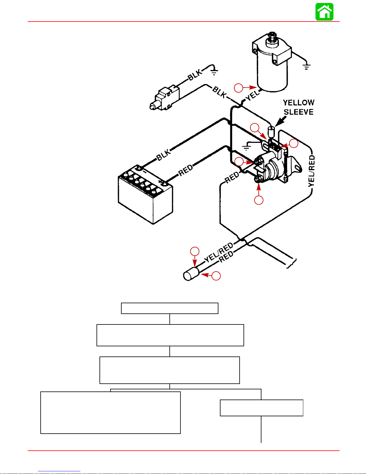
BATTERY CHARGING AND STARTING SYSTEMS
7
2
3
6
4
5
Starting Circuit Troubleshooting Flow Chart
Starter Motor Does Not Turn
SAFETY WARNING: Disconnect BLACK (w/YELLOW
sleeve) cable from starter solenoid test point 1BEFORE
making tests to prevent unexpected engine cranking.
TEST 1
Useanohmmeter(R x 1scale)andconnect meterleads
between NEGATIVE(-) battery post and common powerhead ground.
1
To Rectifier
53056
No Continuity Indicated
Thereisanopencircuitin theBLACKNEGATIVE(-)battery cable between the NEGATIVE (-) battery post and
the powerhead.
· Check cable for loose or corroded connections.
· Check cable for open.
Page 2B-12 90-826883R2 JUNE 1998
Continuity Indicated
Proceed to TEST 2, on next page.
Page 75

BATTERY CHARGING AND STARTING SYSTEMS
TEST 2
a. Connect voltmeter between common engine ground and Test Point 2.
No voltage reading;
proceed to TEST 3.
b. Push start switch.
TEST 3
a. Connect voltmeter between common engine ground and Test Point 3.
b. Push Start Switch.
No voltage reading;
proceed to TEST 4.
12 Volt Reading
Defective starter solenoid.
Neutral start switch on lower engine cowl is open
or BLACK or WHITE switch leads are disconnected
or damaged. Proceed to TEST 7.
TEST 4
a. Connect voltmeter between common
No voltage reading;
proceed to TEST 5.
engine ground and Test Point 4.
b. Push Start Switch.
TEST 5
No voltage reading;
proceed to TEST 6.
Connect voltmeter between common
engine ground and Test Point 5.
* Battery Voltage
12 Volt Reading*
Check BLACK ground wire for poor connection or open circuit. Reconnect ground wire to
starter solenoid; proceed to TEST 7.
Electric Start Tiller Handle Model
12 Volt Reading*
Neutral start switch is open, or YELLOW/RED
wire is open between Test Points 4 and 3.
12 Volt Reading*
Defective ignition switch.
TEST 6
Connect voltmeter between common engine ground and Test Point 6.
No voltage reading; check RED wire between battery (+) positive terminal and Test
Point 6.
TEST 7
a. Connect voltmeter between common engine ground and Test Point 1.
b. Push Start Switch.
No voltage reading; Defective
starter solenoid.
TEST 8
a. Reconnect BLACK (starter motor) cable to starter solenoid Test Point 1.
b. Connect voltmeter between common engine ground and Test Point 7
c. Push Start Switch.
No voltage reading; check BLACK cable
for poor connection or open circuit.
12 Volt Reading*
Check fuse in RED wire between test points 5 and 6.
Check for open RED wire between test points 5 and 6.
12 Volt Reading*
Should hear solenoid click; proceed to TEST 8.
12 Volt Reading*
Check BLACK ground cable at starter for
loose or corroded connection, or open circuit. If cable is O.K., check starter motor.
90-826883R2 JUNE 1998 Page 2B-13
Page 76

BATTERY CHARGING AND STARTING SYSTEMS
Commander 2000 Key Switch Test
1. Disconnect remote control wiring harness and instrument panel connector.
2. Set ohmmeter on R x 1 scale for the following tests:
KEY
POSITION
OFF
RUN
START
CHOKE*
CONTINUITY SHOULD BE INDICATED AT THE FOLLOWING POINTS:
BLK BLK/YEL RED YEL/RED PUR YEL/BLK
*NOTE: Keyswitch mustbe positionedto “RUN” or “START” and key pushed in to
actuate choke for this test.
3. Ifmeter readingsare other thanspecified inthe precedingtests,verify thatswitch and
not wiring is faulty. If wiring checks ok, replace switch.
Page 2B-14 90-826883R2 JUNE 1998
Page 77
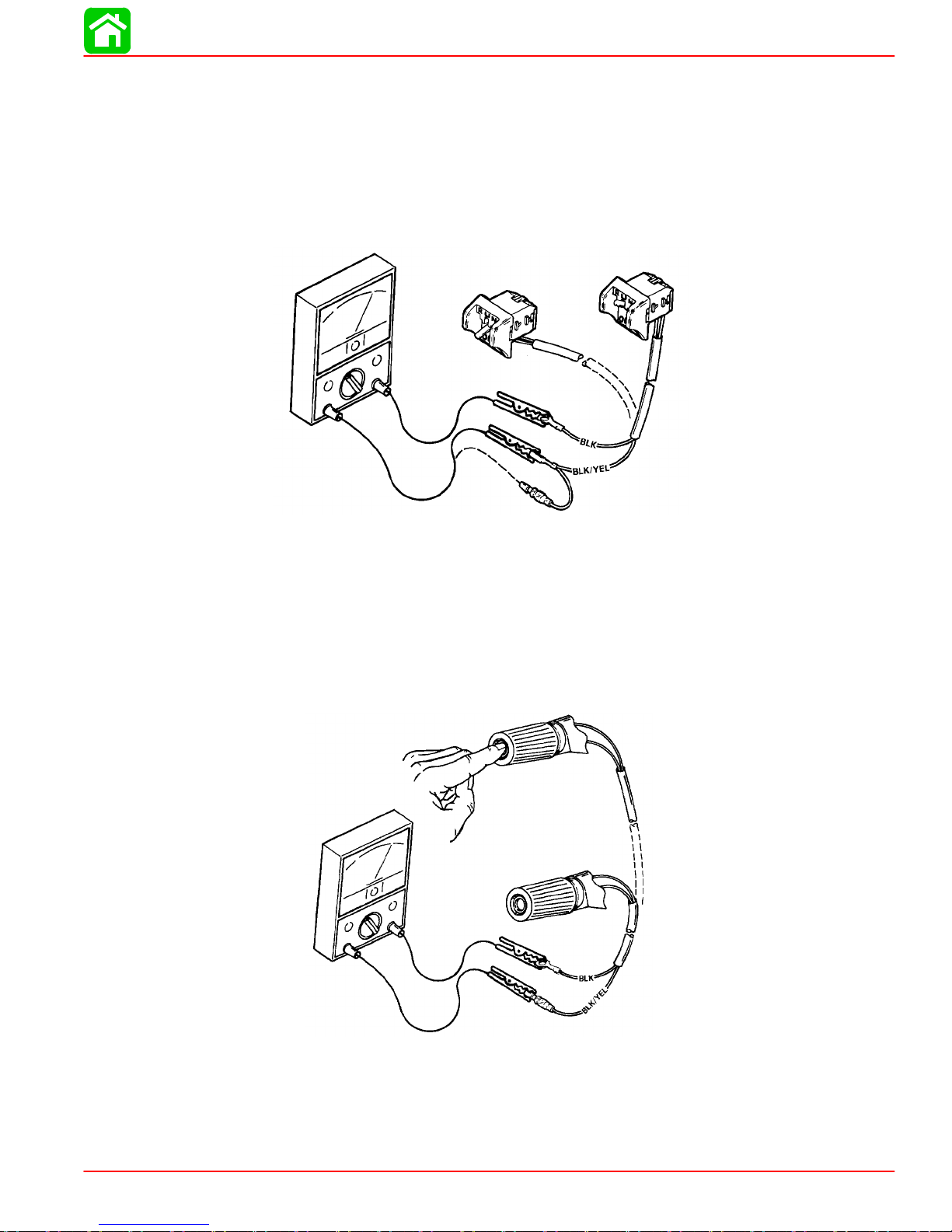
Emergency Stop Switch
(Lanyard Type)
IMPORTANT: Refer to Section 2D “Wiring Diagrams” for wiring connections.
1. Disconnect emergency stop switch leads from engine wiring.
2. Use an ohmmeter and perform the following tests.
BATTERY CHARGING AND STARTING SYSTEMS
3. If meter readings are other than specified, replace emergency stop switch.
Push Button Stop Switch
IMPORTANT: Refer to Section 2D “Wiring Diagrams” for wiring connections.
1. Disconnect push button stop switch leads from engine wiring.
“OFF”
CONTINUITY
(1 Ohm or Less)
“RUN”
NO CONTINUITY
(¥)
23421
2. Use an ohmmeter and perform the following tests.
CONTINUITY
(I Ohm or Less)
NO CONTINUITY
(¥)
23421
3. If meter readings are other than specified, replace push button stop switch.
90-826883R2 JUNE 1998 Page 2B-15
Page 78
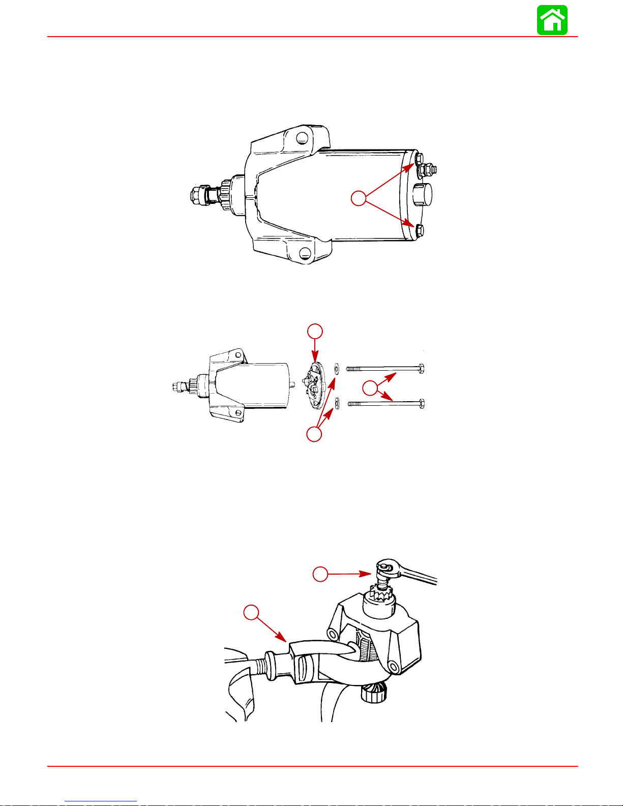
BATTERY CHARGING AND STARTING SYSTEMS
Starter Motor
Disassembly
1. Remove 2 thru bolts from starter.
a - Bolts
2. Lightly tap on end of shaft and lower end cap with rubber mallet. Do not loose brush
springs.
a
a
c
b
53235
a - Lower End Cap
b - Washers
c - Bolts
3. Tap ondrive end capto loosen.Remove end capand armaturefrom starterhousing.
4. If removal of parts that are installed on armature is necessary, hold armature with
Strap Wrench (91-24937A1) and remove locknut (and discard) from end of shaft.
b
a
a - Strap Wrench (91-24937A1)
b - Locknut (discard)
Page 2B-16 90-826883R2 JUNE 1998
53081
Page 79

5. Remove parts from shaft.
a
a - Locknut
b - Spacer
c - Spring
d - Drive Assembly
e - Drive End Cap
f - Armature Shaft
g - Helix Threads
h - Washer
Cleaning and Inspection
1. If brushesare pitted,chipped or wornto lessthan 3/16in. (4.8mm), replace brushes.
BATTERY CHARGING AND STARTING SYSTEMS
e
b
d
c
g
f
h
53228
IMPORTANT: DO NOT clean the starter drive assembly or armature shaft while
startermotor is installedonoutboard. Thecleaningsolution will draindirtinto motor housing.
2. If the motor drive assembly does not fully engage with flywheel, the drive assembly
may bebinding on thehelix threads onthe armature shaftdue to dirtor wear.Locate
cause of binding and correct before reassembling.
3. Clean drive components with cleaning solution and inspect parts for wear.
4. Clean commutatorwith No.00 sandpaper.Remove anyoil fromcommutator. Ifcommutator surface is pitted , rough or worn unevenly, resurface on a lathe.
5. Resurface commutator on a lathe as follows:
a. Usealatheto turndownthecommutatorsurface. DONOTturndown thecommu-
tator surface excessively.
b. Clean copper particles from slots between commutator bars.
c. Sand thecommutator lightlywith No.00 sandpaper toremove burrs.Thoroughly
clean the armature after resurfacing and sanding.
90-826883R2 JUNE 1998 Page 2B-17
Page 80

BATTERY CHARGING AND STARTING SYSTEMS
Testing Motor Armature
TESTING ARMATURE FOR SHORTS
1. Place armature in a growler and switch growler on.
2. Hold hack saw blade over armature core while rotating armature.
3. Ifsawbladevibrates, armatureisshorted.Retest aftercleaningbetweencommutator
bars. If saw blade still vibrates, replace armature.
c
a
b
a - Hack Saw Blade
b - Armature Core
c - Commutator
TESTING ARMATURE FOR GROUND
1. Use anohmmeter (Rx 100) tocheck for“no continuity”between commutator and armature core or commutator and shaft.
2. If continuity exists, armature is grounded and must be replaced.
01440
b
c
a
a - Commutator
b - Armature Core
c - Shaft
Page 2B-18 90-826883R2 JUNE 1998
01441
Page 81
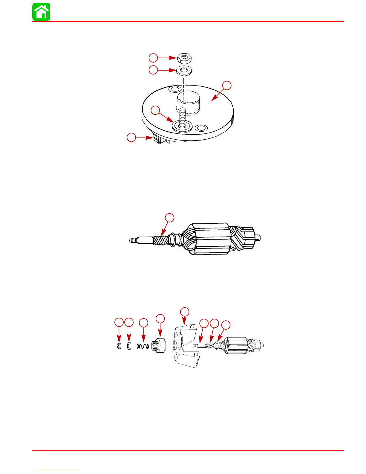
Starter Motor Reassembly
1. Reinstall brush assembly.
a
a - Brush
b - End Cap
c - Fiber Washer
d - Metal Washer
e - Nut
2. Applya drop ofSAE10W oiltoto helixthreadson armatureshaft.DO NOToverlubricate.
BATTERY CHARGING AND STARTING SYSTEMS
e
d
b
c
53075
a
53080
a - Helix Threads
3. Applya drop ofSAE10W oiltobushingsin driveendcap andlower end cap.DONOT
over lubricate
4. Reinstall components on armature shaft. Use a new locknut and tighten securely.
e
a
b
a - Locknut
b - Spacer
c - Spring
d - Drive Assembly
e - Drive End Cap
f - Armature Shaft
g - Helix Threads
h - Washer
d
c
g
f
h
53228
90-826883R2 JUNE 1998 Page 2B-19
Page 82
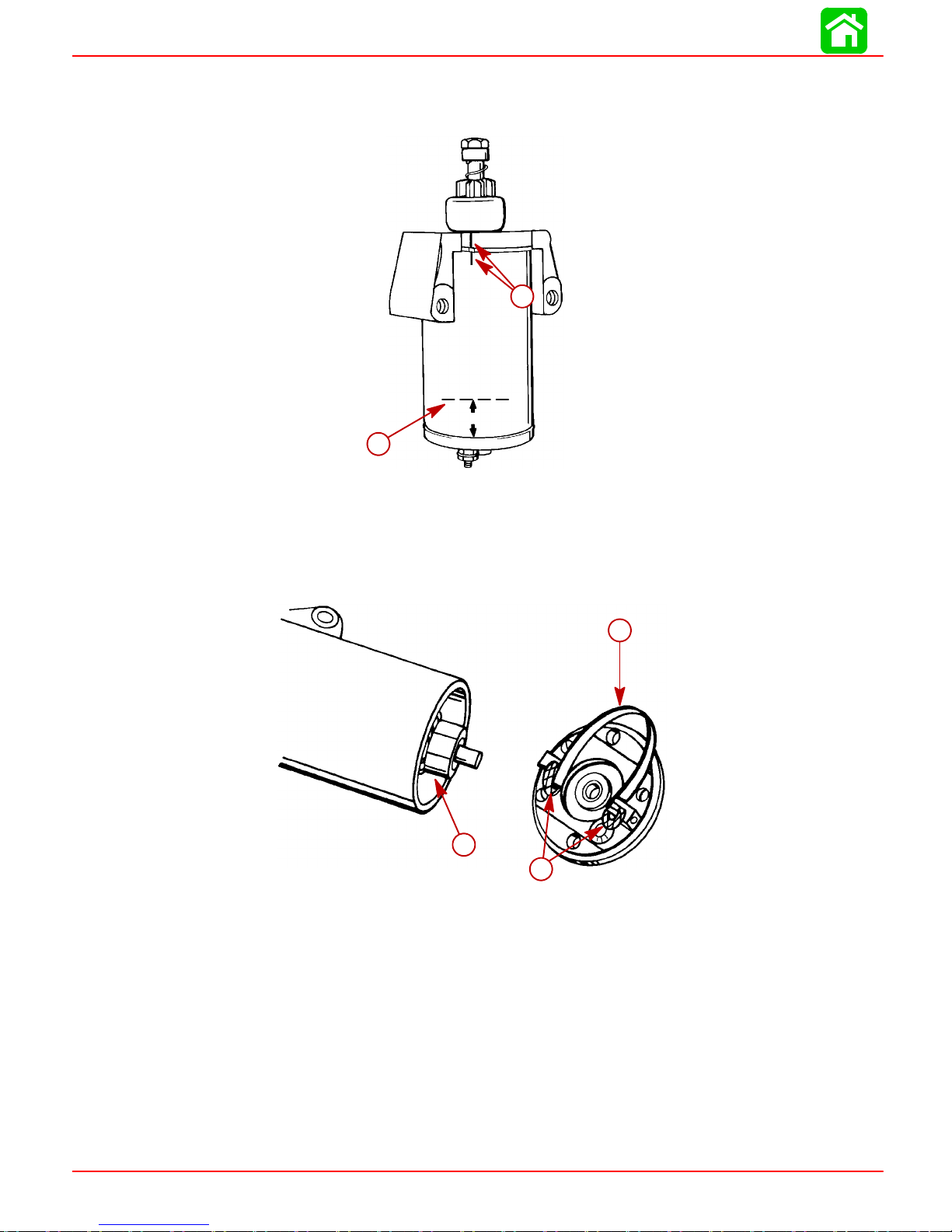
BATTERY CHARGING AND STARTING SYSTEMS
5. Position armature intostarter frame so that commutator end of armature is at end of
starter frame where permanent magnets are recessed 1-5/16 in. (33.3mm). Align
marks as shown.
a - Alignment Marks
b - Bottom Edge of Permanent Magnets
6. Installsprings andbrushes into brushholders. Spreadbrushes andholdin placewith
a strip of spring steel.
a
1-5/16 in.
b
53082
7. Push in on drive end of shaft so that commutator will extend out of starter frame.
b
c
a
53213
a - Brushes
b - Spring Steel
c - Commutator
Page 2B-20 90-826883R2 JUNE 1998
Page 83

8. Install lower end cap onto starter frame.
a - Alignment Mark; Must Align with Slot
b - Slot
c - Lower End Cap
Starter Solenoid Test
Test starter solenoid as follows:
1. Disconnect all leads from solenoid terminals.
2. Usean ohmmeter,setto (Rx 1scale) andconnect betweensolenoidterminals 3and
4.
BATTERY CHARGING AND STARTING SYSTEMS
c
a
b
53083
3. Connect a 12-volt supply between solenoid terminals 1 and 2. Solenoid should click
and meter should read zero ohms.
4. If meter does not read zero ohms (full continuity), replace solenoid.
4
1
a - Ohmmeter Leads
b - 12-Volt Supply
90-826883R2 JUNE 1998 Page 2B-21
a
2
3
b
14354
Page 84

BATTERY CHARGING AND STARTING SYSTEMS
Flywheel Ring Gear
Installation
IMPORTANT:Before installingring gear on flywheel, inspectgear and flywheel for
paint runs which will prevent ring gear from laying flat against flywheel.
1. Inspect (and remove) any paint runs on ring gear and/or mounting surface on flywheel.
2. Place gear on flywheel with countersink side of mounting holes toward the outside.
3. Apply Loctite271 to threads of4 gear mounting screws and secure gear to flywheel.
Torque screws to 100 lb. in. (11.3 N·m).
a
c
b
a - Ring Gear
b - Flywheel
c - Screws [Torque to 100 lb. in. (1 1.3 N·)]
53240
Page 2B-22 90-826883R2 JUNE 1998
Page 85
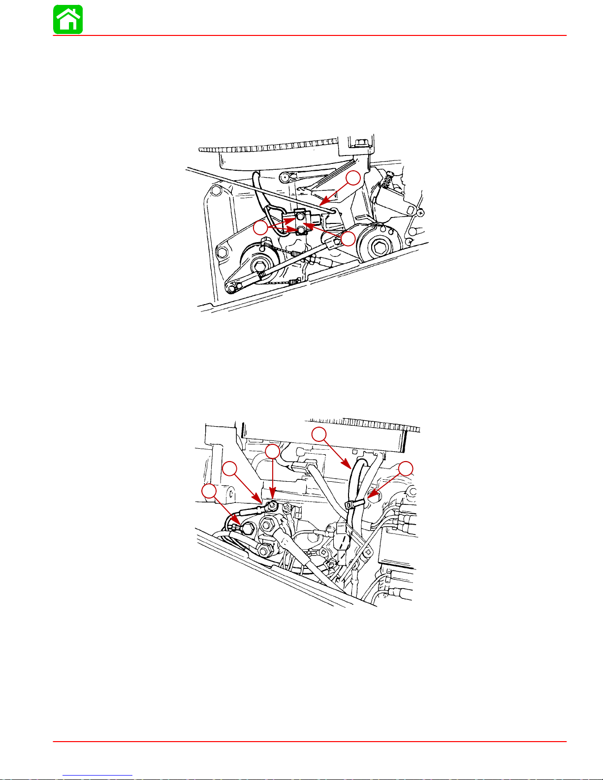
BATTERY CHARGING AND STARTING SYSTEMS
Neutral Start Switch (Electric Start Tiller Handle Shift
Models)
1. Mount neutral start switch onto control platform with 2 bolts and plate.
2. Torque mounting bolts to 5 lb. in. (0.6 N·m).
a
c
b
53077
a - Neutral Start Switch
b - Plate
c - Bolts [Torque to 5 lb in. (0.6 N·m)]
3. Route switch harness over block. Secure harness to stator harness with sta-strap.
4. Route harness behind rectifier. Attach BLACK lead to solenoid mount bolt. Attach
Black lead with YELLOW sleeve to terminal 1 of starter solenoid.
a
d
c
e
b
53076
a - Switch Harness
b - BLACK Lead
c - BLACK Lead with YELLOW Sleeve
d - Terminal 1
e - Sta-strap
90-826883R2 JUNE 1998 Page 2B-23
Page 86

BATTERY CHARGING AND STARTING SYSTEMS
Tiller Handle Start Button
1. The tiller handlestart button assembly is secured to the tiller handleby 2 semi-loops
which snapfit ontothe tillerthrottle shaft.Toremove the button assembly, prythe assembly away from the tiller handle with a flat tip screw driver.
2. The starter button harness is routed into the lower cowl through the fuel connector
access hole.
b
d
a
c
53216
a - Start Button Assembly
b - Semi-Loops
c - Harness
d - Fuel Connector
3. The starter button harness is routed down the PORT side of lower engine to cowl.
4. The RED harness lead is connected to the POSITIVE (+) terminal of the rectifier.
Torque attaching nut to 25 lb. in. (2.8 N·m).
5. The YELLOW/RED harness lead attaches to the #2 terminal of the starter terminal.
Torque attaching nut to 15 lb. in. (1.7 N·m).
a
b
a - RED Lead [T orque nut to 25 lb. in. (2.8 N·m)]
b - YELLOW/RED Lead [Torque nut to 15 lb. in. (1.7 N·m)]
Page 2B-24 90-826883R2 JUNE 1998
53215
Page 87
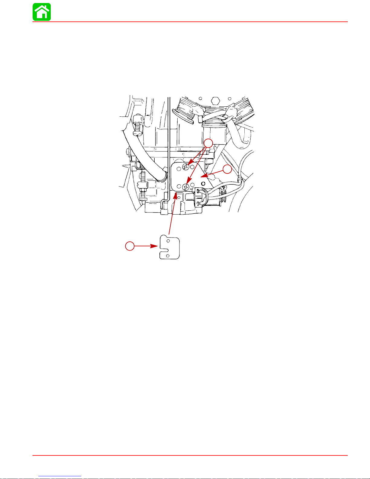
Choke Solenoid
Installation
IMPORTANT: New gasket MUST be positioned as shown when being installed.
1. Install new gasket with solenoid plate assembly.
2. Secure assembly with 2 screws. Torque screws to 18 lb. in. (2.0 N·m).
BATTERY CHARGING AND STARTING SYSTEMS
c
b
a
a - Gasket
b - Solenoid Plate
c - Screws [Torque to 18 lb. in. (2.0 N·m)]
53209
90-826883R2 JUNE 1998 Page 2B-25
Page 88
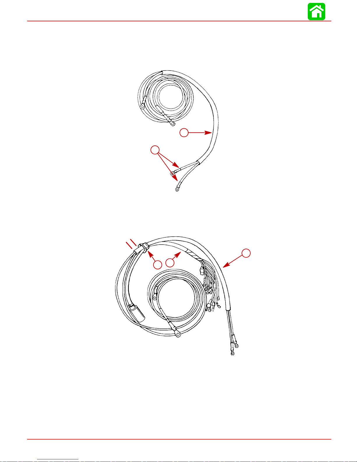
BATTERY CHARGING AND STARTING SYSTEMS
Battery Cables/Engine Wiring Harness (Remote Electric
Start Models)
1. Slide battery cables through sleeve.
b
a
53066
a - Battery Cables
b - Sleeve
2. Thread battery cable/sleeve through wire retainer of engine wiring harness. Verify1
in. (25.4mm) of sleeve remains to the outside of wire retainer.
1 in. (25.4mm)
a
c
b
53065
a - Sleeve
b - Retainer
c - Harness
Page 2B-26 90-826883R2 JUNE 1998
Page 89

BATTERY CHARGING AND STARTING SYSTEMS
3. Remove carburetor as outlined in Section 3.
4. Thread engine wiringharness first and then battery cable/sleeve through openingin
bottom cowl.
c
a
b
53210
a - Harness
b - Battery Cable/Sleeve
c - Opening
5. Route engine wiring harness and battery cable/sleeve (under carburetor location)
around to PORT side of cylinder block.
90-826883R2 JUNE 1998 Page 2B-27
Page 90

BATTERY CHARGING AND STARTING SYSTEMS
6. Push wire retainer into opening of bottom cowl and secure with clip.
a - Clip
7. Secure harness and battery cable/sleeve with sta-strap just inside bottom cowl.
8. Reinstall carburetor as outlined in Sec 3A.
a
53068
a - Sta-strap
9. Secure fuse holder in J-clip.
b
a
53226
a
a - Fuse Holder
b - J-clip
Page 2B-28 90-826883R2 JUNE 1998
Page 91
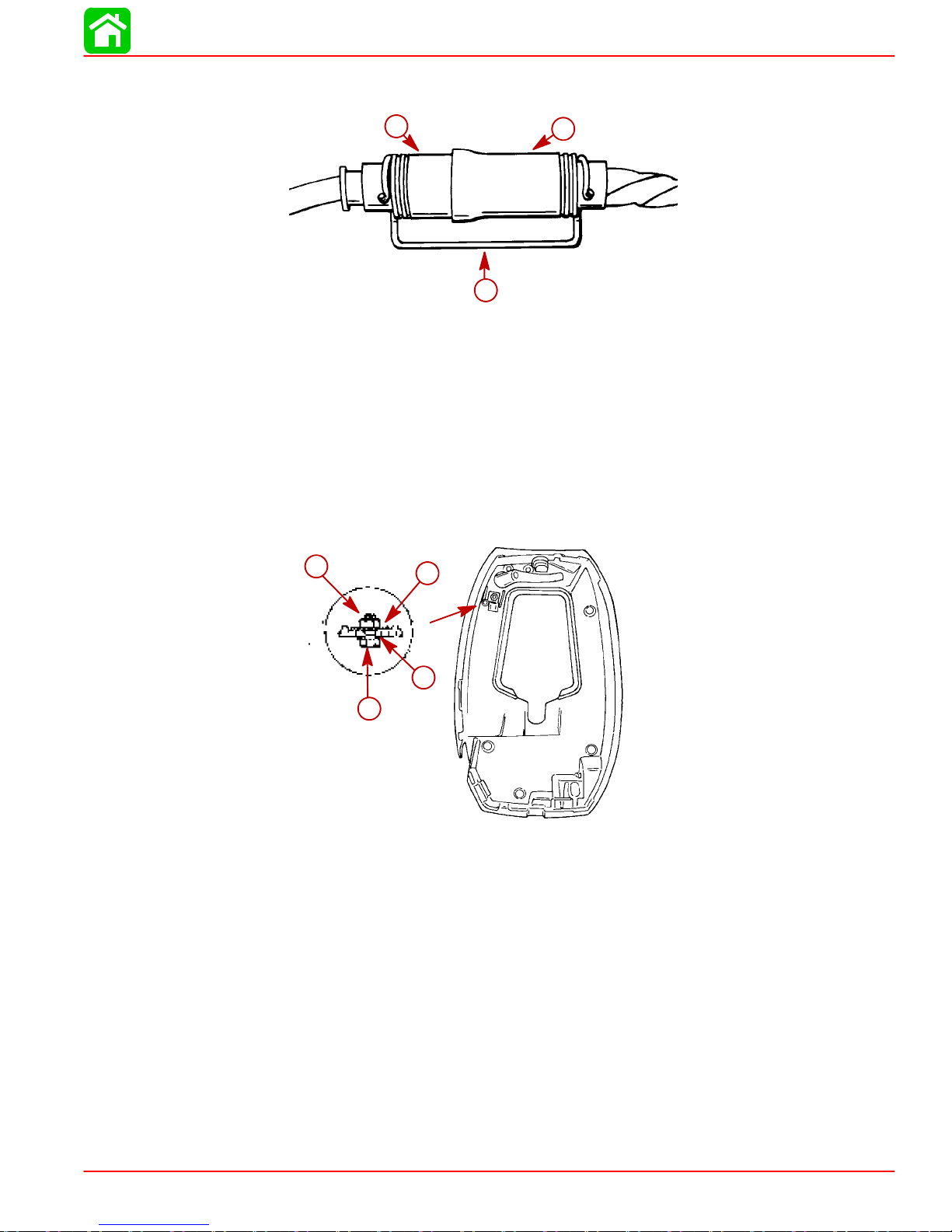
BATTERY CHARGING AND STARTING SYSTEMS
10. Plugremote controlharness connectorinto enginewiring harnessconnector andsecure with harness connector retainer.
b
c
a - Remote Control Harness
b - Engine Harness
c - Retainer
a
53064
Battery Cables (Tiller Handle Push Button Electric Start
Models)
Installation
1. Fasten harness clamp to bottom cowl with nut, washer and bolt.
b
a
a - Clamp
b - Nut
c - Washer
d - Bolt
c
d
53069
90-826883R2 JUNE 1998 Page 2B-29
Page 92

BATTERY CHARGING AND STARTING SYSTEMS
2. Slide battery cables through sleeve.
3. Slide harness clampover battery cable sleeve and position cablesinto bottom cowl.
4. Position harness clamp onto clamp bracket in bottom cowl. Tighten clamp securely.
a - Clamp
b - Bracket
5. Slide battery cable grommetover battery cables and install grommet into openingin
starboard bottom cowl.
b
a
53067
a - Grommet
b - Cables
b
a
53149
Page 2B-30 90-826883R2 JUNE 1998
Page 93

Plug Harness (Battery Charging Kit)
Installation
1. Install plug harness through fuel fitting opening in bottom cowl.
2. Route harness along PORT side of engine to rectifier.
BATTERY CHARGING AND STARTING SYSTEMS
a
a - Harness
3. Refer to Section 2D for wiring connections.
Emergency Stop Switch (Lanyard Type)
Installation
1. Route emergency stop switch wiring through opening in STARBOARD bottomcowl.
a
a - Stop Switch
2. Secure stop switch into opening in bottom cowl using clip.
53063
53054
a - Clip
3. Refer to Section 2D for wiring connections.
90-826883R2 JUNE 1998 Page 2B-31
a
53055
Page 94

Section 2C - Timing/Synchronizing/Adjusting
Table of Contents
TIMING/SYNCHRONIZING/ADJUSTING
ELECTRICAL
2
Specifications 2C-1. . . . . . . . . . . . . . . . . . . . . . . . . . . . . . . .
Special Tools 2C-2. . . . . . . . . . . . . . . . . . . . . . . . . . . . . . . .
Timing/Synchronizing/
Adjusting-Tiller Handle & Side Shift Models 2C-3. . . . . .
Side Shift Models: Adjusting Tiller Handle
Cables 2C-4. . . . . . . . . . . . . . . . . . . . . . . . . . . . . . . . . . .
Tiller Shift Models: Adjusting Link Rod 2C-5. . . . . . .
Starting Procedure 2C-6. . . . . . . . . . . . . . . . . . . . . . . .
Timing Checking and Adjustment 2C-6. . . . . . . . . . . .
Adjusting Idle Speed 2C-8. . . . . . . . . . . . . . . . . . . . . . .
Specifications
TIMING
SPECIFI-
CA TIONS
20 Jet 19941/2 THRU 1998
20/25 1994
Electronic Spark Advance
20 Jet 1999 AND NEWER
20/25 1997 AND NEWER
Mechanical Spark Advance
1
/2 THRU 1996
Idle @ 750 ± 50 RPM (In Forward
Gear)
Fast Idle Speed
Maximum BTDC (Running)
Setup Timing
Idle @ 750 ± 50 RPM (In Forward
Gear)
Fast Idle Speed
Maximum BTDC (Running)
20 Jet/20/25 Models (Non Marathon/SeaPro) 2C-10
Timing/Synchronizing/Adjusting - Remote Control
Models 2C-10. . . . . . . . . . . . . . . . . . . . . . . . . . . . . . . . . . . .
Shift and Throttle Cable Installation to the
Outboard 2C-13. . . . . . . . . . . . . . . . . . . . . . . . . . . . . . .
Shift Cable Installation 2C-14. . . . . . . . . . . . . . . . . . .
Throttle Cable Installation 2C-15. . . . . . . . . . . . . . . .
Starting Procedure 2C-16. . . . . . . . . . . . . . . . . . . . . . . . .
Adjusting Idle Speed 2C-17. . . . . . . . . . . . . . . . . . . . .
4°±2° B.T.D.C (Not Adjustable)
1400 RPM ± 250 RPM
25°±1 @5500 RPM
28° B.T.D.C. @ 3000 ± 200 R.P.M.
(Set-up timing of 28° B.T.D.C. will
be retarded to 25° B.T.D.C. @
5500 R.P.M.)
6°±1° B.T.D.C
1500 RPM ± 200 RPM
25°±1 @5500 RPM
C
90-826883R2 JUNE 1998 Page 2C-1
Page 95
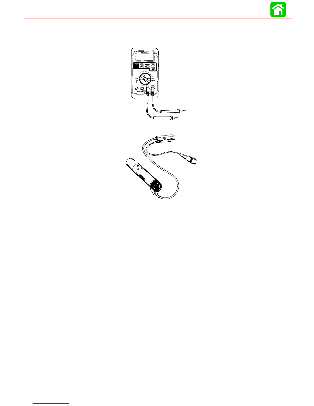
TIMING/SYNCHRONIZING/ADJUSTING
Special Tools
1. DMT 2000 Service Tachometer 91-854009A1*
2. Timing Light 91-99379*
*May be obtained locally.
Page 2C-2 90-826883R2 JUNE 1998
Page 96
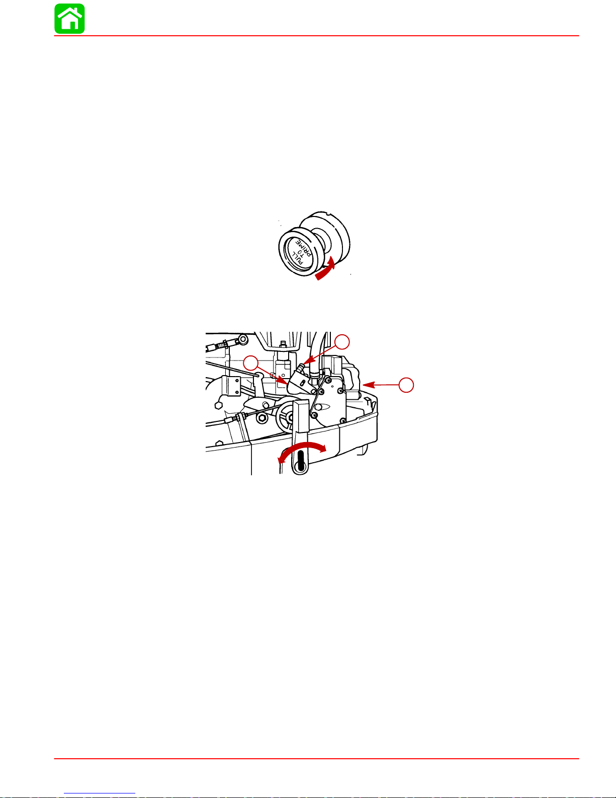
Timing/Synchronizing/Adjusting
Tiller Handle & Side Shift Models
NOTE: Timing/Synchronizing adjustments are the same for tiller and side shift models
unless otherwise specified.
1. Check all electrical connections to ensure they are tight and secure (including battery
connections on electric start models).
2. Shift outboard to “Neutral”, (on side shift model place throttle twist grip to “Slow”).
3. Push choke/primer all the way “In”. On models equipped with a primer, turn knob to
full “Counterclockwise” position.
4. Check the tiller handle cables for proper adjustment. If necessary , adjust cables and
remove any slack.
5. With the outboard placed in “Neutral”, back the idle speed screw off the cam follower .
TIMING/SYNCHRONIZING/ADJUSTING
b
R
a- Idle Speed Screw
b- Cam Follower
c- Side Shift Model Shown
a
c
N
F
28192
90-826883R2 JUNE 1998 Page 2C-3
Page 97
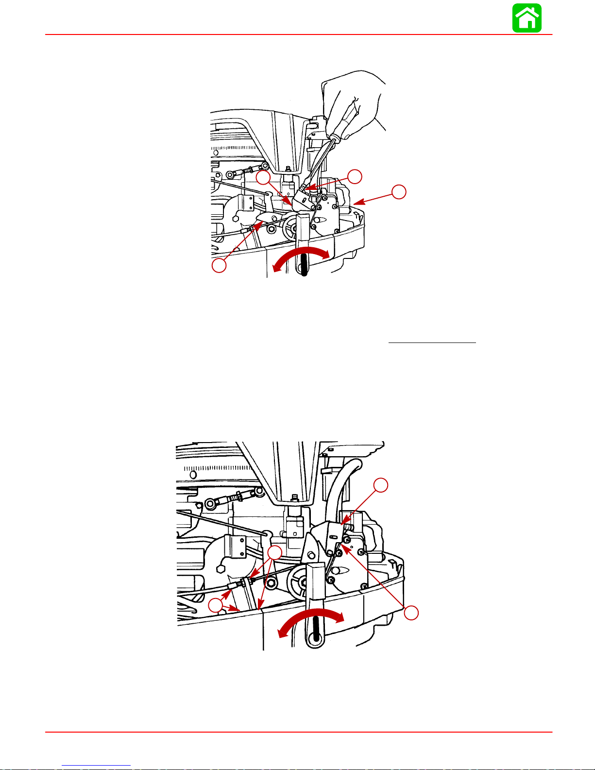
TIMING/SYNCHRONIZING/ADJUSTING
6. Turn idle speed screw “In” until the cam follower just makes contact with throttle cam
then turn “In” one additional turn to slightly open throttle plate.
a
N
c
R
F
b
a- Cam Follower
b- Idle Speed Screw
c- Throttle Cam
d- Side Shift Model Shown
NOTE: The throttle return spring on cam follower plate should just contact the fuel pump
housing at wide open throttle position. (Do not allow the throttle spring to act as a
throttle stop).
7. Place throttle twist grip to “Full Throttle” position. Verify that the throttle plate can
achieve wide open throttle. If adjustment is necessary, adjust tiller cables or throttle
link rod as shown.
Side Shift Models: Adjusting Tiller Handle Cables
d
28194
a- Cam Follower Plate
b- Fuel Pump Housing
c- Throttle Cables
Page 2C-4 90-826883R2 JUNE 1998
a
c
c
N
R
F
b
28192
Page 98

Tiller Shift Models: Adjusting Link Rod
c
a- Contact Point (spring to just contact fuel pump housing)
b- Throttle Return Spring
c- Throttle Link Rod
8. Remove access plug from carburetor air intake cover.
TIMING/SYNCHRONIZING/ADJUSTING
a
b
52912
9. Turn idle mixture screw in (clockwise) until LIGHTL Y seated then back out to an initial
setting (See Specifications Chart)
a
b
28195
a- Access Plug
b- Idle Mixture Screw (Behind Access Plug)
WARNING
Keep clear of propeller while cranking and running the outboard motor
10. With the outboard in water, connect fuel line to engine, squeeze bulb until firm, and
check for carburetor flooding.
11. Check choke operation, making sure choke shutter opens and closes all the way.
IMPORTANT: (Local Electric Start Models Only) Check the neutral start micro
switch for proper operation. Try to start the engine in the “Forward”, “Neutral”, and
“Reverse” gear with the electric start button. The engine must start in “Neutral
Only”.
90-826883R2 JUNE 1998 Page 2C-5
Page 99

TIMING/SYNCHRONIZING/ADJUSTING
Starting Procedure
15XD/25 SEAPRO/MARATHON MODELS ONLY
NOTE: Outboards equipped with a thermostat will have a “Sporadic” tell tail water dis-
charge.
Pull choke to full “OUT” position and start the engine. Immediately after the engine starts,
push the choke knob to “Full In” position. Check for water at the tell tale and at the idle
relief holes. (Tell tale pressure to be per General Specifications).
20 JET/20/25 MODELS
NOTE: Outboards equipped with a thermostat will have a “Sporadic” tell tail water dis-
charge.
Turn primer enrichener knob fully clockwise and pull to the “Full Out” position two (2)
times, waiting approximately five (5) seconds between pulls, leaving the knob out after
the second pull.
Start the engine. Immediately after the engine starts, push the primer knob to “Full In”
position and check for water at the tell tail and idle relief holes. Allow the engine to warm
up then turn the primer knob to the “Full Counterclockwise” position. (Tell tale pressure
to be per General Specifications).
WARNING
To prevent personal injury or possible death, from loss of balance or stability
while servicing the motor, DO NOT attempt to check or adjust timing while boat
is in motion. Failure to follow one of the recommended servicing procedures may
result in the person falling overboard or causing personal injury from fall in boat.
Timing Checking and Adjustment
IMPORT ANT: When checking the set-up timing with the engine running, one of the
following test procedures must be followed.
Check maximum timing per the set-up specification
• IN TEST TANK
• IN BACK-IN TEST TANK
• ON DYNAMOMETER
• WHILE STILL SECURED ON BOAT TRAILER “Backed in the Water”
while running the outboard:
Page 2C-6 90-826883R2 JUNE 1998
Page 100

ELECTRONIC SPARK ADVANCE MODELS
1
/
THRU 1996 AND 20 JET 19941/2 THRU 1998
20/25 1994
2
1. Using approved test procedure, place the outboard in “Forward” gear and check
set-up timing. (If not within specifications, adjustment will be required).
TIMING/SYNCHRONIZING/ADJUSTING
BTDC
a
a- Timing Mark
b- Side Shift Model Shown
To prevent personal injury from spinning flywheel, Do Not attempt to adjust the
trigger link rod (Maximum Timing Adjustment) with engine running.
ADJUSTING SET-UP TIMING
With the engine “OFF”, snap the trigger link rod socket off ball stud and:
3040
20
b
28192
WARNING
• Extend rod length to “Advance” timing
• Shorten rod length to “Retard” timing
Snap link rod onto ball stud, re-start the engine and check set-up timing specification.
a
b
28192
a- Trigger Link Rod (Set-up Timing Adjustment)
b- Side Shift Model Shown
90-826883R2 JUNE 1998 Page 2C-7
 Loading...