

Page 1

Operation
Maintenance
and
Installation
Manual
© 2017 Mercury Marine
150, 150 SeaPro FourStroke
8M0133564 517 eng
Page 2

eng
Page 3
Welcome
You have selected one of the finest marine power packages available. It
incorporates numerous design features to ensure operating ease and durability.
With proper care and maintenance, you will enjoy using this product for many
boating seasons. To ensure maximum performance and carefree use, we ask
that you thoroughly read this manual.
The Operation and Maintenance Manual contains specific instructions for using
and maintaining your product. We suggest that this manual remain with the
product for ready reference whenever you are on the water.
Thank you for purchasing one of our products. We sincerely hope your boating
will be pleasant!
Mercury Marine, Fond du Lac, Wisconsin, U.S.A.
Name / function:
John Pfeifer, President,
Mercury Marine
Read This Manual Thoroughly
IMPORTANT: If you do not understand any portion of this manual, contact your
dealer. Your dealer can also provide a demonstration of actual starting and
operating procedures.
Notice
Throughout this publication, and on your power package, warnings, cautions,
and notices, accompanied by the International Hazard Symbol
!
, may be
used to alert the installer and user to special instructions concerning a
particular service or operation that may be hazardous if performed incorrectly
or carelessly. Observe them carefully.
These safety alerts alone cannot eliminate the hazards that they signal. Strict
compliance with these special instructions while performing the service, plus
common sense operation, are major accident prevention measures.
!
WARNING
Indicates a hazardous situation which, if not avoided, could result in death or
serious injury.
!
CAUTION
Indicates a hazardous situation which, if not avoided, could result in minor or
moderate injury.
eng i
Page 4

NOTICE
Indicates a situation which, if not avoided, could result in engine or major
component failure.
IMPORTANT: Identifies information essential to the successful completion of
the task.
NOTE: Indicates information that helps in the understanding of a particular step
or action.
IMPORTANT: The operator (driver) is responsible for the correct and safe
operation of the boat, the equipment aboard, and the safety of all occupants
aboard. We strongly recommend that the operator read this Operation and
Maintenance Manual and thoroughly understand the operational instructions for
the power package and all related accessories before the boat is used.
!
WARNING
The engine exhaust from this product contains chemicals known to the state
of California to cause cancer, birth defects or other reproductive harm.
The serial numbers are the manufacturer’s keys to numerous engineering
details that apply to your Mercury Marine power package. When contacting
Mercury Marine about service, always specify model and serial numbers.
Descriptions and specifications contained herein were in effect at the time this
was approved for printing. Mercury Marine, whose policies are based on
continuous improvement, reserves the right to discontinue models at any time
or to change specifications or designs without notice and without incurring
obligation.
Warranty Message
The product you have purchased comes with a limited warranty from Mercury
Marine; the terms of the warranty are set forth in the Warranty Manual included
with the product. The Warranty Manual contains a description of what is
covered, what is not covered, the duration of coverage, how to best obtain
warranty coverage, important disclaimers and limitations of damages, and
other related information. Please review this important information.
Mercury Marine products are designed and manufactured to comply with our
own high quality standards, applicable industry standards and regulations, as
well as certain emissions regulations. At Mercury Marine every engine is
operated and tested before it is boxed for shipment to make sure that the
product is ready for use. In addition, certain Mercury Marine products are
tested in a controlled and monitored environment, for up to 10 hours of engine
run time, in order to verify and make a record of compliance with applicable
standards and regulations. All Mercury Marine product, sold as new, receives
the applicable limited warranty coverage, whether the engine participated in
one of the test programs described above or not.
ii eng
Page 5

Copyright and Trademark Information
© MERCURY MARINE. All rights reserved. Reproduction in whole or in
part without permission is prohibited.
Alpha, Axius, Bravo One, Bravo Two, Bravo Three, GO BOLDLY., Circle M with
Waves Logo, K‑planes, Mariner, MerCathode, MerCruiser, Mercury, Mercury
with Waves Logo, Mercury Marine, Mercury Precision Parts, Mercury
Propellers, Mercury Racing, MotorGuide, OptiMax, Quicksilver, SeaCore,
Skyhook, SmartCraft, Sport‑Jet, Verado, VesselView, Zero Effort, Zeus, #1 On
the Water and We're Driven to Win are registered trademarks of Brunswick
Corporation. Pro XS is a trademark of Brunswick Corporation. Mercury Product
Protection is a registered service mark of Brunswick Corporation.
Identification Records
Please record the following applicable information:
Outboard
Engine Model and Horsepower
Engine Serial Number
Gear Ratio
Propeller Number Pitch Diameter
Hull Identification Number (HIN) Purchase Date
Boat Manufacturer Boat Model Length
Exhaust Gas Emissions Certification Number (Europe Only)
eng iii
Page 6

eng iv
Page 7

General Information
Boater's Responsibilities..................................................................................... 1
Before Operating Your Outboard........................................................................ 1
Boat Horsepower Capacity................................................................................. 1
High‑Speed and High‑Performance Boat Operation.......................................... 2
Propeller Selection..............................................................................................2
Outboard Remote Control Models ..................................................................... 4
Remote Steering Notice......................................................................................5
Lanyard Stop Switch........................................................................................... 5
Protecting People in the Water........................................................................... 8
Passenger Safety Message ‑ Pontoon Boats and Deck Boats...........................8
Wave and Wake Jumping................................................................................. 10
Impact with Underwater Hazards......................................................................10
Exhaust Emissions........................................................................................... 12
Selecting Accessories for Your Outboard......................................................... 14
Safe Boating Recommendations...................................................................... 14
Recording Serial Number................................................................................. 17
Specifications 150.............................................................................................17
Specifications 150 SeaPro................................................................................18
Component Identification.................................................................................. 20
Transporting
Trailering Boat/Outboard.................................................................................. 21
Fuel and Oil
Fuel Requirements........................................................................................... 22
Fuel Additives................................................................................................... 23
Low Permeation Fuel Hose Requirement ........................................................ 23
Quick‑Disconnect Fuel Hose Fitting................................................................. 23
EPA Pressurized Portable Fuel Tank Requirements........................................ 24
Fuel Demand Valve (FDV) Requirement.......................................................... 24
Mercury Marine's Pressurized Portable Fuel Tank........................................... 25
Filling Fuel Tank............................................................................................... 26
Engine Oil Recommendations.......................................................................... 26
Checking and Adding Engine Oil...................................................................... 27
eng v
Page 8

Features and Controls
Remote Control Features................................................................................. 30
Warning System............................................................................................... 30
Power Trim and Tilt...........................................................................................32
Propeller Steering Torque—Trim Tab Adjustment............................................ 35
Operation
Important Daily Inspection Before Each Use ................................................... 36
Prestarting Check List.......................................................................................36
Operating in Freezing Temperatures................................................................ 37
Operating in Saltwater or Polluted Water......................................................... 37
Operating at High Elevations............................................................................ 37
Effects of Elevation and Weather on Performance........................................... 37
Setting Trim Angle while Running Engine at Idle Speed.................................. 38
Operating in Shallow Water.............................................................................. 38
Engine Break‑in Procedure...............................................................................39
Starting the Engine........................................................................................... 39
Gear Shifting..................................................................................................... 42
Stopping the Engine......................................................................................... 42
Maintenance
Cleaning Care Recommendations.................................................................... 43
EPA Emissions Regulations............................................................................. 45
Inspection and Maintenance Schedule............................................................. 46
Maintenance Schedule Decal (150 FourStroke)............................................... 48
Flushing the Cooling System............................................................................ 49
Top Cowl Removal and Installation.................................................................. 50
Battery Inspection ............................................................................................ 51
Fuel System...................................................................................................... 51
Corrosion Control Anode.................................................................................. 53
Propeller Bore Sleeve Inspection—If Equipped ...............................................54
Propeller Replacement..................................................................................... 55
Spark Plug Inspection and Replacement..........................................................58
Fuse Replacement............................................................................................60
Alternator Drive Belt Inspection........................................................................ 62
Lubrication Points............................................................................................. 62
Checking Power Trim Fluid...............................................................................65
Changing Engine Oil ........................................................................................ 65
Gearcase Lubrication........................................................................................68
vi eng
Page 9

Storage
Storage Preparation..........................................................................................70
Protecting External Outboard Components...................................................... 70
Protecting Internal Engine Components........................................................... 71
Gearcase.......................................................................................................... 71
Positioning Outboard for Storage..................................................................... 71
Battery Storage................................................................................................. 71
Troubleshooting
Starter Motor Will Not Crank the Engine........................................................... 72
Engine Will Not Start.........................................................................................72
Engine Runs Erratically.................................................................................... 72
Performance Loss.............................................................................................73
Battery Will Not Hold Charge............................................................................ 73
Owner Service Assistance
Service Assistance........................................................................................... 74
Ordering Literature............................................................................................76
Outboard Installation
Mercury Marine Validated Engine Mounting Hardware.................................... 78
Accessories Mounted to the Transom Clamp Bracket...................................... 78
Important Information........................................................................................82
Boat Horsepower Capacity............................................................................... 82
Start in Gear Protection.................................................................................... 83
Fuel System...................................................................................................... 83
Installation Specifications................................................................................. 88
Lifting Outboard................................................................................................ 88
Shipping Bracket Removal............................................................................... 89
Steering Cable ‑ Starboard Side Routed Cable................................................ 90
Steering Link Rod Fasteners (if equipped)....................................................... 90
Determining Recommended Outboard Mounting Height.................................. 92
Drilling Outboard Mounting Holes..................................................................... 93
Fastening the Outboard to the Transom........................................................... 95
Electrical, Fuel Hose, and Control Cables...................................................... 100
eng vii
Page 10

Maintenance Log
Maintenance Log............................................................................................ 112
viii eng
Page 11

Boater's Responsibilities
The operator (driver) is responsible for the correct and safe operation of the
boat and the safety of its occupants and general public. It is strongly
recommended that each operator read and understand this entire manual
before operating the outboard.
Be sure that at least one additional person onboard is instructed in the basics
of starting and operating the outboard and boat handling in case the driver is
unable to operate the boat.
Before Operating Your Outboard
Read this manual carefully. Learn how to operate your outboard properly. If you
have any questions, contact your dealer.
Safety and operating information that is practiced, along with using good
common sense, can help prevent personal injury and product damage.
This manual as well as safety labels posted on the outboard use the following
safety alerts to draw your attention to special safety instructions that should be
followed.
!
WARNING
Indicates a hazardous situation which, if not avoided, could result in death or
serious injury.
!
CAUTION
Indicates a hazardous situation which, if not avoided, could result in minor or
moderate injury.
NOTICE
Indicates a situation which, if not avoided, could result in engine or major
component failure.
Boat Horsepower Capacity
!
WARNING
Exceeding the boat's maximum horsepower rating can cause serious injury
or death. Overpowering the boat can affect boat control and flotation
characteristics or break the transom. Do not install an engine that exceeds
the boat's maximum power rating.
GENERAL INFORMATION
eng 1
Page 12

Do not overpower or overload your boat. Most boats will carry a required
capacity plate indicating the maximum acceptable power and load as
determined by the manufacturer following certain federal guidelines. If in doubt,
contact your dealer or the boat manufacturer.
U.S. COAST GUARD CAP ACITY
MAXIMUM HORSEPOWER XXX
MAXIMUM PERSON
CAPACITY (POUNDS)
XXX
MAXIMUM WEIGHT
CAPACITY
XXX
26777
High‑Speed and High‑Performance Boat Operation
If your outboard is to be used on a high‑speed or high‑performance boat with
which you are unfamiliar, we recommend that you do not operate it at its high
speed capability without first requesting an initial orientation and familiarization
demonstration ride with your dealer or an operator experienced with your boat/
outboard combination. For additional information, obtain a copy of our
Hi‑Performance Boat Operation booklet from your dealer, distributor, or
Mercury Marine.
Propeller Selection
The propeller on your outboard is one of the most important components in the
propulsion system. An improper propeller choice can significantly affect the
performance of your boat and could result in damage to the outboard engine.
When choosing a propeller, a full selection of aluminum and stainless steel
propellers specifically designed for your outboard are available through
Mercury Marine. To view the entire product offering and find the correct
propeller that is best suited for your application, visit
www.mercmarinepropellers.com or see your local authorized Mercury dealer.
SELECTING THE CORRECT PROPELLER
An accurate tachometer for measuring engine speed is important in choosing
the correct propeller.
Choose a propeller for your boating application that will allow the engine to
operate within the specified full throttle operating range. When operating the
boat at full throttle under normal load conditions, the engine RPM should be in
the upper half of the recommended full throttle RPM range. Refer to
Specifications. If engine RPM is above that range, select a propeller of
increased pitch in order to reduce engine RPM. If engine RPM is below the
recommended range, select a propeller of reduced pitch to increase engine
RPM.
GENERAL INFORMATION
2 eng
Page 13
IMPORTANT: To ensure proper fit, and performance, Mercury Marine
recommends the use of Mercury or Quicksilver branded propellers and
mounting hardware.
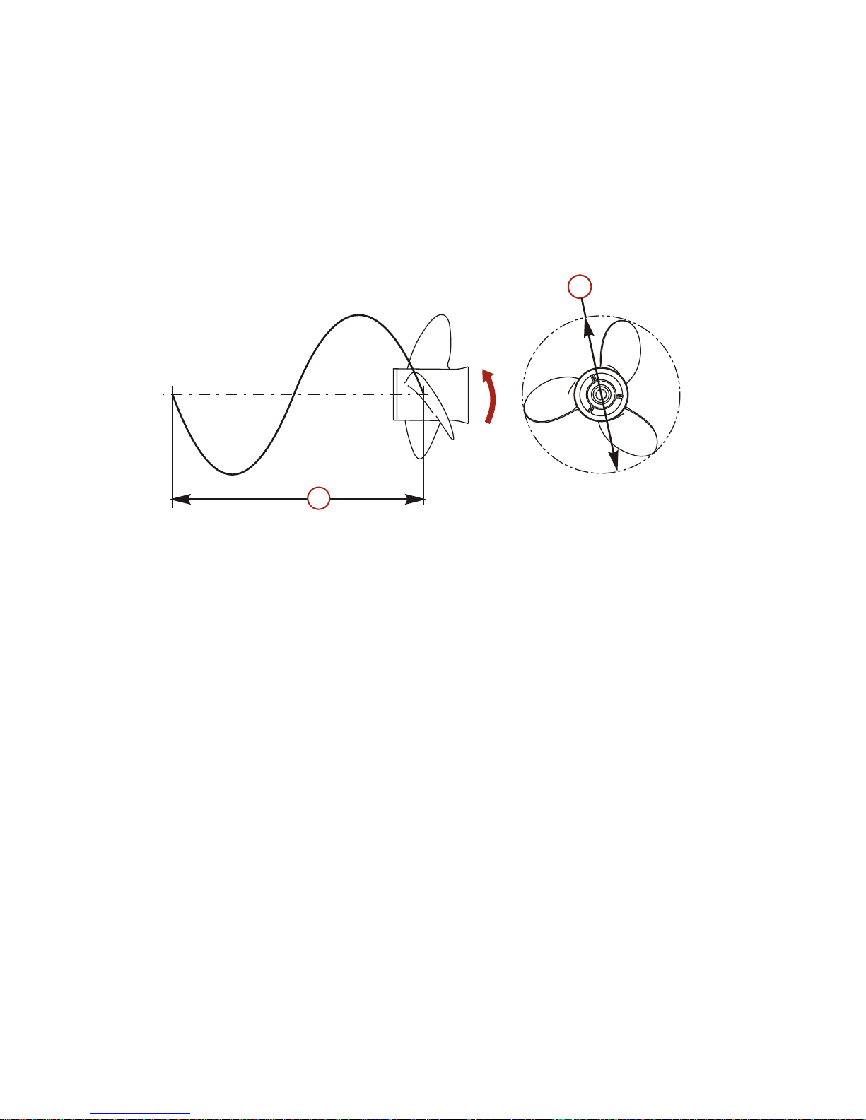
Propellers are designated by the diameter, pitch, number of blades, and
material. The diameter and pitch are stamped (cast) into the side or the end of
the propeller hub. The first number represents the diameter of the propeller and
the second number represents the pitch. For example, 14x19 represents a
propeller with a 14 inch diameter and 19 inches of pitch.
a - Diameter
b - Pitch ‑ Travel during one revolution
The following are some propeller basics that will help you determine the correct
propeller for your boating application.
Diameter ‑ The diameter is the distance across the imaginary circle that is
made when the propeller rotates. The correct diameter for each propeller has
been predetermined for the design of your outboard. However, when more than
one diameter is available for the same pitch, use a larger diameter for heavy
boat applications and a smaller diameter for lighter applications.
Pitch ‑ The pitch is the theoretical distance, in inches, that a propeller travels
forward during one revolution. Pitch can be thought of similar to gears in a car.
The lower the gear, the faster the car will accelerate, but with lower overall top
speed. Likewise, a lower pitch propeller will accelerate quickly, but top‑end
speed will be reduced. The higher the propeller pitch the faster the boat will
usually go; though typically slowing acceleration.
Determining the correct pitch size ‑ First, check the full throttle RPM under
normal load condition. If the full throttle RPM is within the recommended range,
select a replacement or upgrade propeller with the same pitch as the current
propeller.
• Adding 1 inch of pitch will reduce the full throttle RPM by 150 to 200
• Subtracting 1 inch of pitch will increase full throttle RPM by 150 to 200
a
b
22669
GENERAL INFORMATION
eng 3
Page 14
• Upgrading from a 3‑blade propeller to a 4‑blade propeller will generally
decrease full throttle RPM by 50 to 100
IMPORTANT: Avoid damage to the engine. Never use a propeller that allows
the engine to exceed the recommended full throttle RPM range when under
normal full throttle operation.
PROPELLER MATERIAL
Most propellers manufactured by Mercury Marine are made from either
aluminum or stainless steel. Aluminum is suitable for general purpose use and
is standard equipment on many new boats. Stainless steel is over five times
more durable than aluminum and typically provides performance gains in
acceleration and top end speed due to design efficiencies. Stainless steel
propellers also come in a larger variety of sizes and styles that allow you to dial
in the ultimate performance for your boat.
3 BLADE VS. 4 BLADE
Available in many sizes of both aluminum and stainless, 3 and 4‑blade
propellers have unique performance characteristics. In general, 3‑blade
propellers offer good all around performance and higher top speed than
4‑blade propellers. However, 4‑blade propellers are usually faster to plane and
more efficient at cruising speeds, but lack the top end speed of a 3‑blade
propeller.
Outboard Remote Control Models
The remote control connected to your outboard must be equipped with a start
in neutral only protection device. This prevents the engine from starting when
the shift is actuated in any position other than neutral.
!
WARNING
Starting the engine with the drive in gear can cause serious injury or death.
Never operate a boat that does not have a neutral‑safety‑protection device.
N
58237
GENERAL INFORMATION
4 eng
Page 15
Remote Steering Notice
Models with steering link rod ‑ The steering link rod that connects the steering
cable to the engine must be fastened utilizing self‑locking nuts. These
self‑locking nuts must never be replaced with common nuts (nonlocking) as
they will work loose and vibrate off, freeing the link rod to disengage.
!
WARNING
Improper fasteners or improper installation procedures can result in
loosening or disengagement of the steering link rod. This can cause a
sudden, unexpected loss of boat control, resulting in serious injury or death
due to occupants being thrown within or out of the boat. Always use required
components and follow instructions and torque procedures.
a - Self‑locking nuts
Lanyard Stop Switch
The purpose of a lanyard stop switch is to turn off the engine when the operator
moves far enough away from the operator's position (as in accidental ejection
from the operator's position) to activate the switch. Tiller handle outboards and
some remote control units are equipped with a lanyard stop switch. A lanyard
stop switch can be installed as an accessory ‑ generally on the dashboard or
side adjacent to the operator's position.
A decal near the lanyard stop switch is a visual reminder for the operator to
attach the lanyard to their personal flotation device (PFD) or wrist.
a
a
47823
GENERAL INFORMATION
eng 5
Page 16
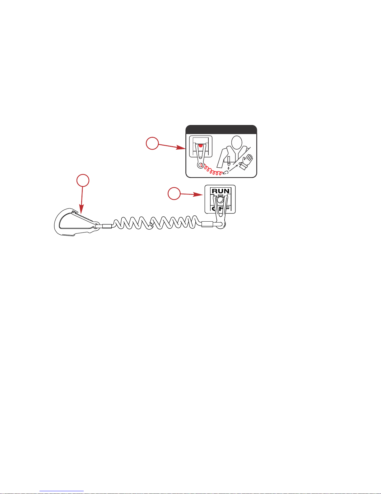
The lanyard cord is usually 122–152 cm (4–5 feet) in length when stretched out,
with an element on one end made to be inserted into the switch and a clip on
the other end for attaching to the operator's PFD or wrist. The lanyard is coiled
to make its at‑rest condition as short as possible to minimize the likelihood of
lanyard entanglement with nearby objects. Its stretched‑out length is made to
minimize the likelihood of accidental activation should the operator choose to
move around in an area close to the normal operator's position. If it is desired
to have a shorter lanyard, wrap the lanyard around the operator's wrist or leg,
or tie a knot in the lanyard.
a - Lanyard cord clip
b - Lanyard decal
c - Lanyard stop switch
Read the following Safety Information before proceeding.
Important Safety Information: The purpose of a lanyard stop switch is to stop
the engine when the operator moves far enough away from the operator's
position to activate the switch. This would occur if the operator accidentally falls
overboard or moves within the boat a sufficient distance from the operator's
position. Falling overboard and accidental ejections are more likely to occur in
certain types of boats such as low sided inflatables, bass boats, high
performance boats, and light, sensitive handling fishing boats operated by a
hand tiller. Falling overboard and accidental ejections are also likely to occur as
a result of poor operating practices such as sitting on the back of the seat or
gunwale at planing speeds, standing at planing speeds, sitting on elevated
fishing boat decks, operating at planing speeds in shallow or obstacle infested
waters, releasing your grip on a steering wheel or tiller handle that is pulling in
one direction, drinking alcohol or consuming drugs, or daring high speed boat
maneuvers.
c
a
b
53910
OFF
RUN
ATTACH LANYARD
GENERAL INFORMATION
6 eng
Page 17
While activation of the lanyard stop switch will stop the engine immediately, a
boat will continue to coast for some distance depending upon the velocity and
degree of any turn at shut down. However, the boat will not complete a full
circle. While the boat is coasting, it can cause injury to anyone in the boat's
path as seriously as the boat would when under power.
We strongly recommend that other occupants be instructed on proper starting
and operating procedures should they be required to operate the engine in an
emergency (if the operator is accidentally ejected).
!
WARNING
If the operator falls out of the boat, stop the engine immediately to reduce the
possibility of serious injury or death from being struck by the boat. Always
properly connect the operator to the stop switch using a lanyard.
!
WARNING
Avoid serious injury or death from deceleration forces resulting from
accidental or unintended stop switch activation. The boat operator should
never leave the operator's station without first disconnecting the stop switch
lanyard from the operator.
Accidental or unintended activation of the switch during normal operation is
also a possibility. This could cause any, or all, of the following potentially
hazardous situations:
• Occupants could be thrown forward due to unexpected loss of forward
motion ‑ a particular concern for passengers in the front of the boat who
could be ejected over the bow and possibly struck by the gearcase or
propeller.
• Loss of power and directional control in heavy seas, strong current, or
high winds.
• Loss of control when docking.
KEEP THE LANYARD STOP SWITCH AND LANYARD CORD IN GOOD
OPERATING CONDITION
Before each use, check to ensure the lanyard stop switch works properly. Start
the engine and stop it by pulling the lanyard cord. If the engine does not stop,
have the switch repaired before operating the boat.
Before each use, visually inspect the lanyard cord to ensure it is in good
working condition and that there are no breaks, cuts, or wear to the cord.
Check that the clips on the ends of the cord are in good condition. Replace any
damaged or worn lanyard cords.
GENERAL INFORMATION
eng 7
Page 18
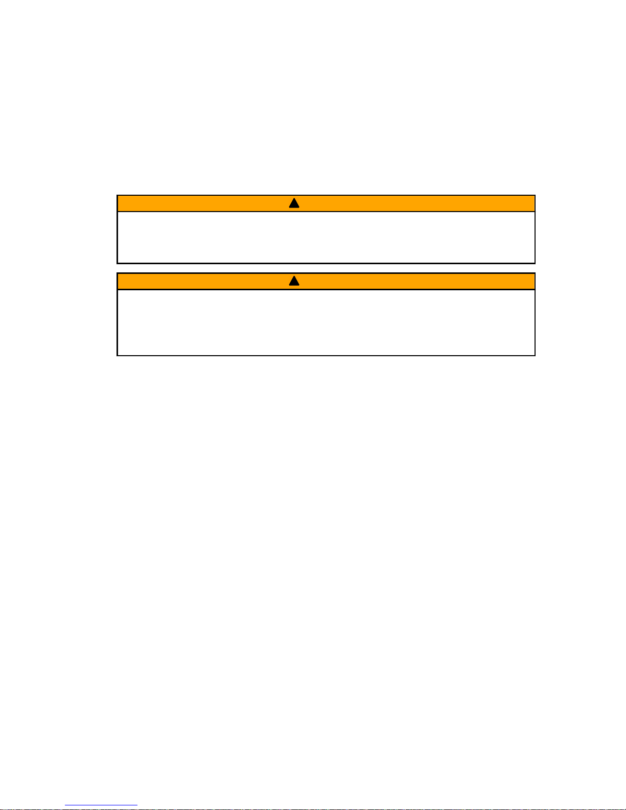
Protecting People in the Water
WHILE YOU ARE CRUISING
It is very difficult for a person standing or floating in the water to take quick
action to avoid a boat heading in his/her direction, even at slow speed.
21604
Always slow down and exercise extreme caution any time you are boating in an
area where there might be people in the water.
Whenever a boat is moving (coasting) and the outboard gear shift is in neutral
position, there is sufficient force by the water on the propeller to cause the
propeller to rotate. This neutral propeller rotation can cause serious injury.
WHILE THE BOAT IS STATIONARY
!
WARNING
A spinning propeller, a moving boat, or any solid device attached to the boat
can cause serious injury or death to swimmers. Stop the engine immediately
whenever anyone in the water is near your boat.
Shift the outboard into neutral and shut off the engine before allowing people to
swim or be in the water near your boat.
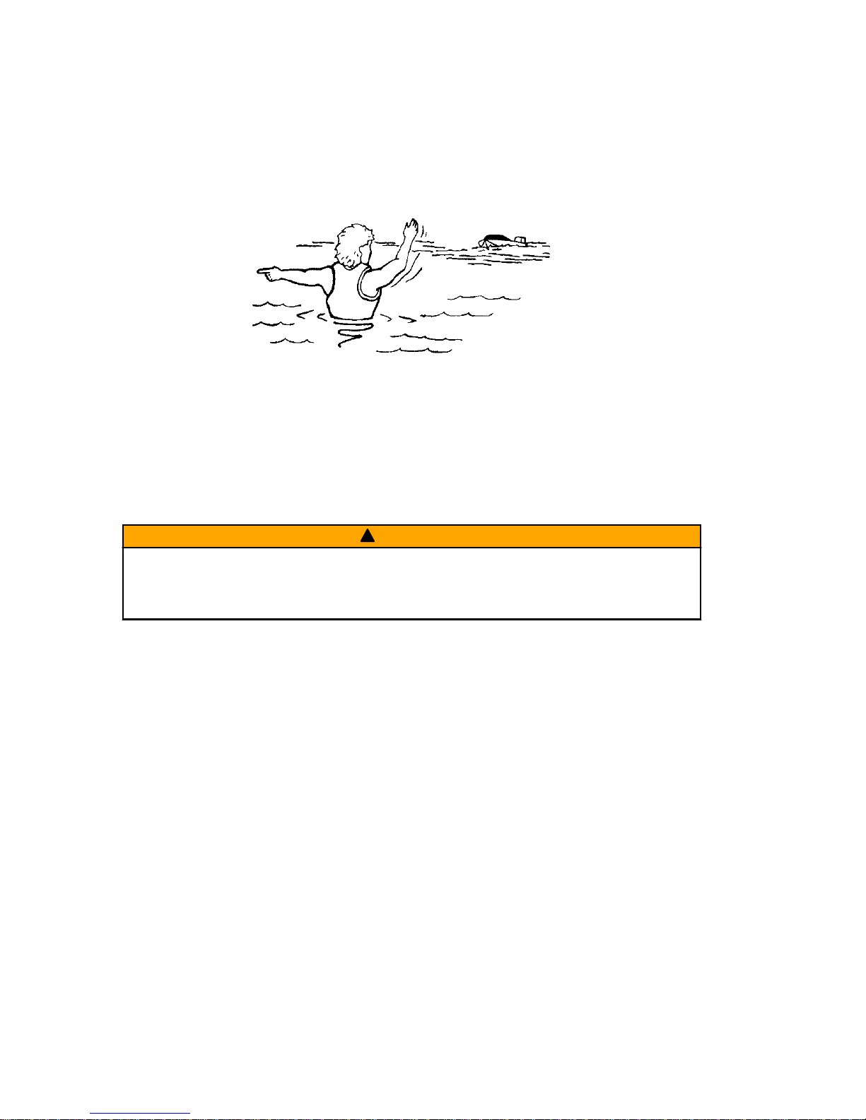
Passenger Safety Message ‑ Pontoon Boats and Deck Boats
Whenever the boat is in motion, observe the location of all passengers. Do not
allow any passengers to stand or use seats other than those designated for
traveling faster than idle speed. A sudden reduction in boat speed, such as
plunging into a large wave or wake, a sudden throttle reduction, or a sharp
change of boat direction, could throw them over the front of the boat. Falling
over the front of the boat between the two pontoons will position them to be run
over by the outboard.
BOATS HAVING AN OPEN FRONT DECK
No one should ever be on the deck in front of the fence while the boat is in
motion. Keep all passengers behind the front fence or enclosure.
GENERAL INFORMATION
8 eng
Page 19
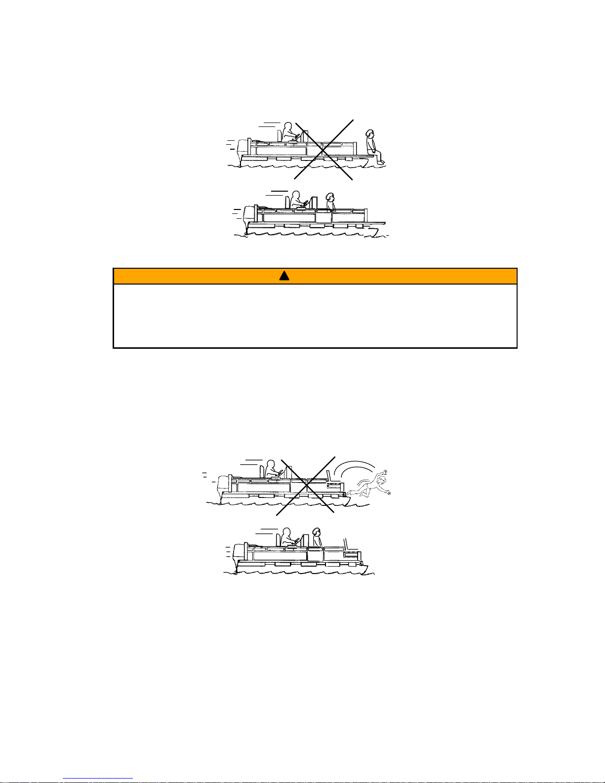
Persons on the front deck could easily be thrown overboard or persons
dangling their feet over the front edge could get their legs caught by a wave
and pulled into the water.
26782
!
WARNING
Sitting or standing in an area of the boat not designed for passengers at
speeds above idle can cause serious injury or death. Stay back from the front
end of deck boats or raised platforms and remain seated while the boat is in
motion.
BOATS WITH FRONT MOUNTED, RAISED PEDESTAL FISHING SEATS
Elevated fishing seats are not intended for use when the boat is traveling faster
than idle or trolling speed. Sit only in seats designated for traveling at faster
speeds.
Any unexpected, sudden reduction in boat speed could result in the elevated
passenger falling over the front of the boat.
26783
GENERAL INFORMATION
eng 9
Page 20

Wave and Wake Jumping
Operating recreational boats over waves and wake is a natural part of boating.
However, when this activity is done with sufficient speed to force the boat hull
partially or completely out of the water, certain hazards arise, particularly when
the boat enters the water.
26784
The primary concern is the boat changing direction while in the midst of the
jump. In such case, the landing may cause the boat to veer violently in a new
direction. Such a sharp change in direction can cause occupants to be thrown
out of their seats, or out of the boat.
!
WARNING
Wave or wake jumping can cause serious injury or death from occupants
being thrown within or out of the boat. Avoid wave or wake jumping whenever
possible.
There is another less common hazardous result from allowing your boat to
launch off a wave or wake. If the bow of your boat pitches down far enough
while airborne, upon water contact it may penetrate under the water surface
and submarine for an instant. This will bring the boat to a nearly instantaneous
stop and can send the occupants flying forward. The boat may also steer
sharply to one side.
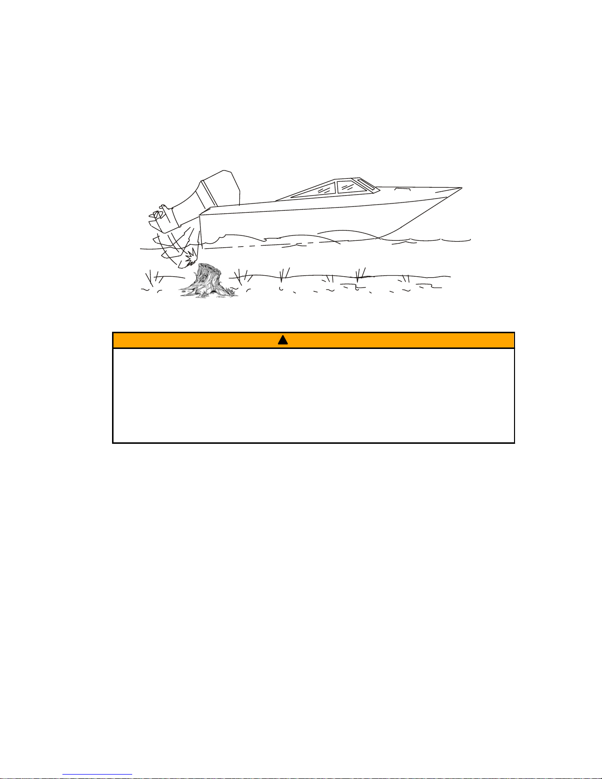
Impact with Underwater Hazards
Your outboard is equipped with a hydraulic trim and tilt system that also
contains a shock absorbing feature. This feature helps the outboard withstand
damage in the case of impact with an underwater object at low to moderate
speeds. At higher speeds, the force of the impact may exceed the system’s
ability to absorb the energy of the impact and cause serious product damage.
No impact protection exists while in reverse. Use extreme caution when
operating in reverse to avoid striking underwater objects.
GENERAL INFORMATION
10 eng
Page 21
Reduce speed and proceed with caution whenever you drive a boat in shallow
water areas or in areas where you suspect underwater obstacles may exist that
could be struck by the outboard or the boat bottom. The most significant
action you can take to help reduce injury or impact damage from striking
a floating or underwater object is to control the boat speed. Under these
conditions, boat speed should be kept to the minimum planing speed,
typically 24 to 40 km/h (15 to 25 mph).
26785
!
WARNING
Avoid serious injury or death from all or part of an outboard or drive unit
coming into the boat after striking a floating or underwater object. When
operating in waters where objects may be at the surface or just under the
surface of the water, reduce your speed and keep a vigilant lookout.
Examples of objects that can cause engine damage are dredging pipes,
bridge supports, wing dams, trees, stumps, and rocks.
Striking a floating or underwater object could result in any of an infinite number
of situations. Some of these situations could yield the following:
• Part of the outboard or the entire outboard could break loose and fly into
the boat.
• The boat could move suddenly in a new direction. A sharp change in
direction can cause occupants to be thrown out of their seats or out of the
boat.
• The boat's speed could rapidly reduce. This will cause occupants to be
thrown forward or even out of the boat.
• The outboard or boat could sustain impact damage.
After striking a submerged object, stop the engine as soon as possible and
inspect it for any broken or loose parts. If damage is present or suspected, the
outboard should be taken to an authorized dealer for a thorough inspection and
necessary repair.
The boat should also be checked for any hull fractures, transom fractures, or
water leaks. If water leaks are discovered after an impact, immediately activate
the bilge pump.
GENERAL INFORMATION
eng 11
Page 22
Operating a damaged outboard could cause additional damage to other parts
of the outboard or could affect control of the boat. If continued running is
necessary, do so at greatly reduced speeds.
!
WARNING
Operating a boat or engine with impact damage can result in product
damage, serious injury, or death. If the vessel experiences any form of
impact, have an authorized Mercury Marine dealer inspect and repair the
vessel or power package.
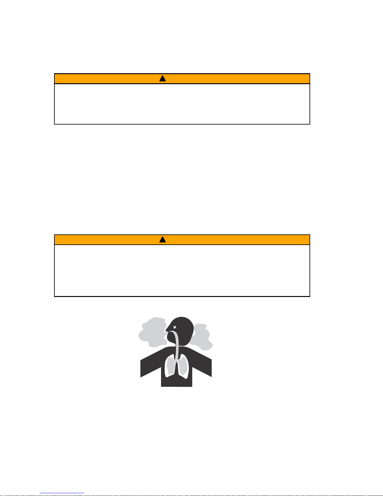
Exhaust Emissions
BE ALERT TO CARBON MONOXIDE POISONING
Carbon monoxide (CO) is a deadly gas that is present in the exhaust fumes of
all internal combustion engines, including the engines that propel boats, and
the generators that power boat accessories. By itself, CO is odorless, colorless,
and tasteless, but if you can smell or taste engine exhaust, you are inhaling
CO.
Early symptoms of carbon monoxide poisoning, which are similar to the
symptoms of seasickness and intoxication, include headache, dizziness,
drowsiness, and nausea.
!
WARNING
Inhaling engine exhaust gases can result in carbon monoxide poisoning,
which can lead to unconsciousness, brain damage, or death. Avoid exposure
to carbon monoxide.
Stay clear from exhaust areas when engine is running. Keep the boat
well‑ventilated while at rest or underway.
STAY CLEAR OF EXHAUST AREAS
41127
co
co
co
co
co
co
co
co
co
co
co
co
co
co
co
co
co
co
co
co
GENERAL INFORMATION
12 eng
Page 23
Engine exhaust gases contain harmful carbon monoxide. Avoid areas of
concentrated engine exhaust gases. When engines are running, keep
swimmers away from the boat, and do not sit, lie, or stand on swim platforms or
boarding ladders. While underway, do not allow passengers to be positioned
immediately behind the boat (platform dragging, teak/body surfing). This
dangerous practice not only places a person in an area of high engine exhaust
concentration, but also subjects them to the possibility of injury from the boat
propeller.
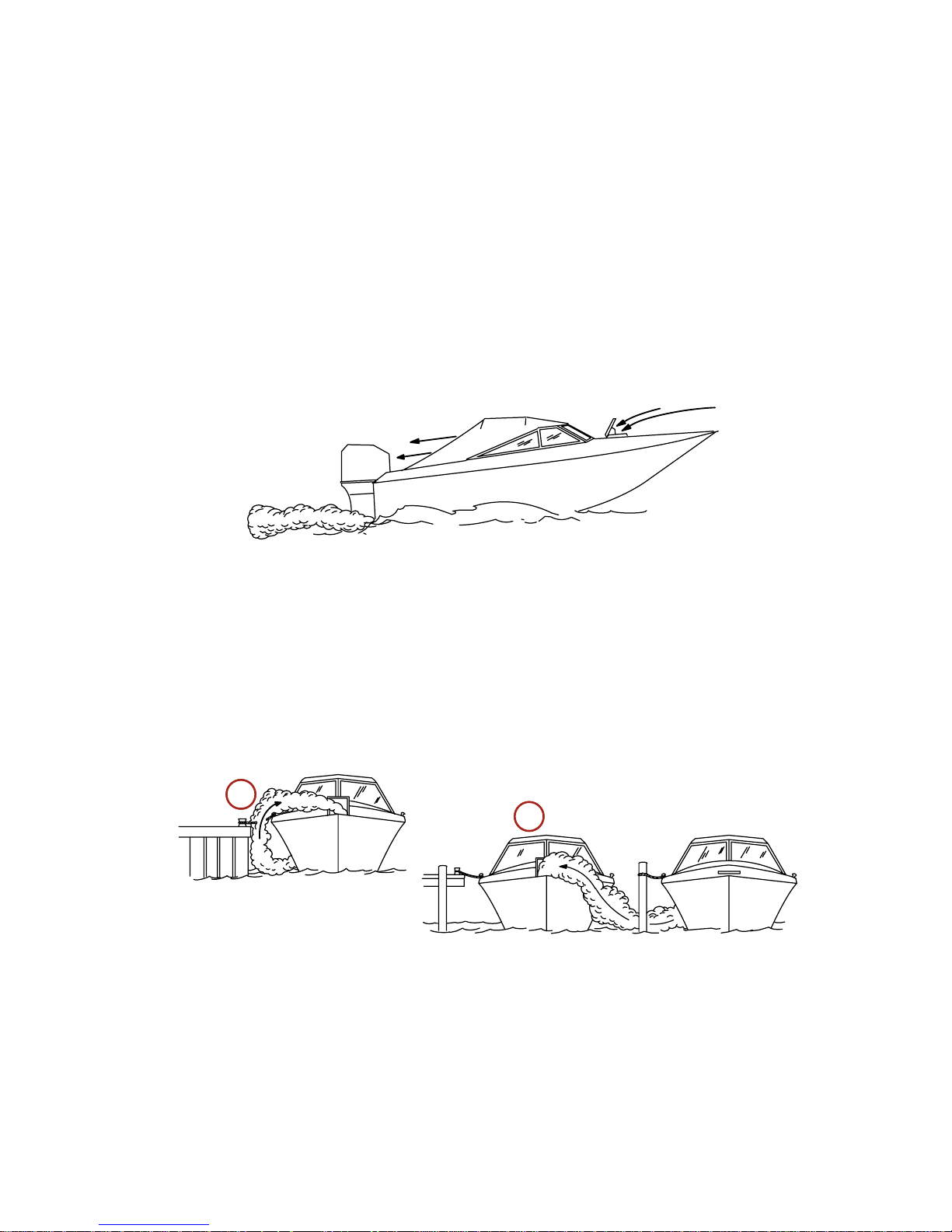
GOOD VENTILATION
Ventilate the passenger area, open side curtains or forward hatches to remove
fumes.
Example of desired air flow through the boat:
21622
POOR VENTILATION
Under certain running and/or wind conditions, permanently enclosed or canvas
enclosed cabins or cockpits with insufficient ventilation may draw in carbon
monoxide. Install one or more carbon monoxide detectors in your boat.
Although the occurrence is rare, on a very calm day, swimmers and
passengers in an open area of a stationary boat that contains, or is near, a
running engine may be exposed to a hazardous level of carbon monoxide.
1. Examples of poor ventilation while the boat is stationary:
a - Operating the engine when the boat is moored in a confined space
b - Mooring close to another boat that has its engine operating
21626
a
b
GENERAL INFORMATION
eng 13
Page 24

2. Examples of poor ventilation while the boat is moving:
a - Operating the boat with the trim angle of the bow too high
b - Operating the boat with no forward hatches open (station wagon effect)
Selecting Accessories for Your Outboard
Genuine Mercury Precision or Quicksilver Accessories have been specifically
designed and tested for your outboard. These accessories are available from
Mercury Marine dealers.
IMPORTANT: Check with your dealer before installing accessories. The misuse
of approved accessories or the use of nonapproved accessories can damage
the product.
Some accessories not manufactured or sold by Mercury Marine are not
designed to be safely used with your outboard or outboard operating system.
Read the installation, operation and maintenance manuals for all your selected
accessories.
Refer to Outboard Installation ‑ Accessories Mounted to the Transom
Clamp Bracket for important information on mounting accessories to the
transom clamp bracket.
Safe Boating Recommendations
To safely enjoy the waterways, familiarize yourself with local and all other
governmental boating regulations and restrictions and consider the following
suggestions.
Know and obey all nautical rules and laws of the waterways.
• We recommend that all powerboat operators complete a boating safety
course. In the U.S., the U.S. Coast Guard Auxiliary, the Power Squadron,
the Red Cross, and your state or provincial boating law enforcement
agency provide courses. For more information in the U.S., call the Boat
U.S. Foundation at 1‑800‑336‑BOAT (2628).
Perform safety checks and required maintenance.
• Follow a regular schedule and ensure that all repairs are properly made.
Check safety equipment onboard.
• Here are some suggestions of the types of safety equipment to carry
when boating:
Approved fire extinguishers
a
b
21628
GENERAL INFORMATION
14 eng
Page 25

Signal devices: flashlight, rockets or flares, flag, and whistle or horn
Tools necessary for minor repairs
Anchor and extra anchor line
Manual bilge pump and extra drain plugs
Drinking water
Radio
Paddle or oar
Spare propeller, thrust hubs, and an appropriate wrench
First aid kit and instructions
Waterproof storage containers
Spare operating equipment, batteries, bulbs, and fuses
Compass and map or chart of the area
Personal flotation device (one per person onboard)
Watch for signs of weather change and avoid foul weather and rough‑sea
boating.
Tell someone where you are going and when you expect to return.
Passenger boarding.
• Stop the engine whenever passengers are boarding, unloading, or are
near the back (stern) of the boat. Shifting the drive unit into neutral is not
sufficient.
Use personal flotation devices.
• Federal law requires that there be a U.S. Coast Guard‑approved life
jacket (personal flotation device), correctly sized and readily accessible
for every person onboard, plus a throwable cushion or ring. We strongly
advise that everyone wear a life jacket at all times while in the boat.
Prepare other boat operators.
• Instruct at least one person onboard in the basics of starting and
operating the engine and boat handling in case the driver becomes
disabled or falls overboard.
Do not overload your boat.
• Most boats are rated and certified for maximum load (weight) capacities
(refer to your boat's capacity plate). Know your boat's operating and
loading limitations. Know if your boat will float if it is full of water. When in
doubt, contact your authorized Mercury Marine dealer or the boat
manufacturer.
Ensure that everyone in the boat is properly seated.
GENERAL INFORMATION
eng 15
Page 26

• Do not allow anyone to sit or ride on any part of the boat that was not
intended for such use. This includes the backs of seats, gunwales,
transom, bow, decks, raised fishing seats, and any rotating fishing seat.
Passengers should not sit or ride anywhere that sudden unexpected
acceleration, sudden stopping, unexpected loss of boat control, or sudden
boat movement could cause a person to be thrown overboard or into the
boat. Ensure that all passengers have a proper seat and are in it before
any boat movement.
Never operate a boat while under the influence of alcohol or drugs. It is
the law.
• Alcohol or drugs can impair your judgment and greatly reduce your ability
to react quickly.
Know your boating area and avoid hazardous locations.
Be alert.
• The operator of the boat is responsible by law to maintain a proper
lookout by sight and hearing. The operator must have an unobstructed
view particularly to the front. No passengers, load, or fishing seats should
block the operator's view when the boat is above idle or planing transition
speed. Watch out for others, the water, and your wake.
Never drive your boat directly behind a water‑skier.
• Your boat traveling at 40 km/h (25 mph) will overtake a fallen skier who is
61 m (200 ft) in front of you in five seconds.
Watch fallen skiers.
• When using your boat for waterskiing or similar activities, always keep a
fallen or down skier on the operator's side of the boat while returning to
attend to the skier. The operator should always have the down skier in
sight and never back up to the skier or anyone in the water.
Report accidents.
• Boat operators are required by law to file a boating accident report with
their state boating law enforcement agency when their boat is involved in
certain boating accidents. A boating accident must be reported if 1) there
is loss of life or probable loss of life, 2) there is personal injury requiring
medical treatment beyond first aid, 3) there is damage to boats or other
property where the damage value exceeds $500.00, or 4) there is
complete loss of the boat. Seek further assistance from local law
enforcement.
GENERAL INFORMATION
16 eng
Page 27
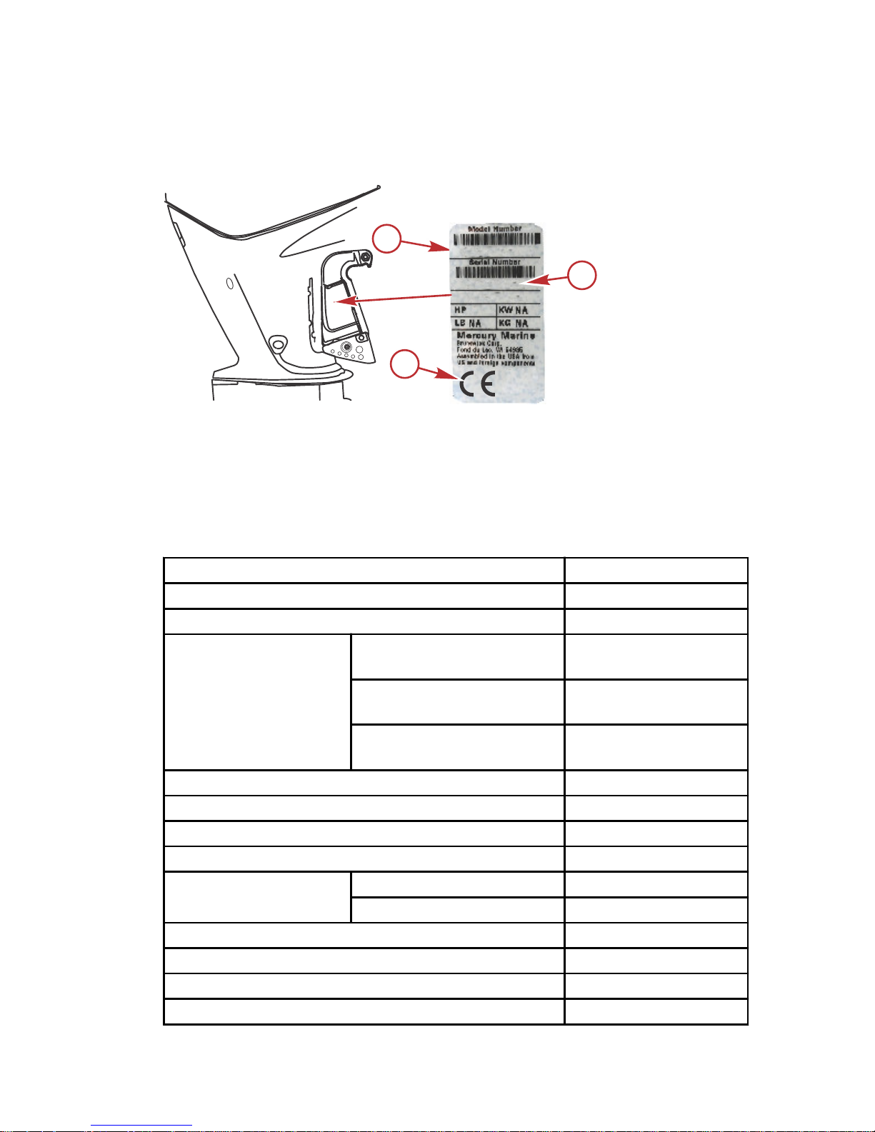
Recording Serial Number
It is important to record this number for future reference. The serial number is
located on the outboard, as shown.
a - Model designation
b - Serial number
c - Certified Europe Insignia (as applicable)
Specifications 150
Horsepower
150
Kilowatts 110
Full throttle RPM range 5000–5800
Idle speed in neutral
gear
In neutral gear cold
warm‑up
650–800 RPM
In neutral gear at operating
temperature
650 RPM
Idle charging
compensation *
650–800 RPM
Number of cylinders 4
Piston displacement 3.0 L (183 cid)
Cylinder bore 101.6 mm (4.0 in.)
Stroke 92 mm (3.62 in.)
Valve clearance
Intake 0.075 mm (0.003 in.)
Exhaust 0.25 mm (0.010 in.)
Recommended spark plug NGK ZFR5F
Spark plug gap 0.8 mm (0.032 in.)
Spark plug hex size 16 mm (5/8 in.)
Spark plug torque 27 Nm (20 lb‑ft)
62550
a
XXXXXXXXX
XXXXXXXX
XXXX
c
b
GENERAL INFORMATION
eng 17
Page 28

Gear ratio 1.92:1
Recommended gasoline
Refer to Fuel and Oil
Recommended oil
Refer to Fuel and Oil
Gearcase lubricant
capacity
Right‑hand rotation
830 mL (28.1 fl oz)
Left‑hand rotation
Engine oil capacity with oil filter replacement 6.0 liters (6.3 US qt)
Battery rating
1000 marine cranking
amps (MCA), 800 cold
cranking amps (CCA),
or 180 ampere hour
(Ah)
Emission control system
Electronic engine
control (EC)
Sound at driver's ear (ICOMIA 39‑94) dBA 82.9
* The idle charging compensation RPM may automatically increase up to 800
RPM to compensate for a low battery charge condition. The increased idle
RPM will charge the battery at a higher rate. Activating the troll control (optional
accessory) will override this low battery charge condition feature.
Specifications 150 SeaPro
Horsepower
150
Kilowatts 110
Full throttle RPM range 4800–5300
Idle speed in neutral
gear
In neutral gear cold
warm‑up
650–800 RPM
In neutral gear at operating
temperature
650 RPM
Idle charging
compensation *
650–800 RPM
Number of cylinders 4
Piston displacement 3.0 L (183 cid)
Cylinder bore 101.6 mm (4.0 in.)
Stroke 92 mm (3.62 in.)
Valve clearance
Intake 0.075 mm (0.003 in.)
Exhaust 0.25 mm (0.010 in.)
Recommended spark plug NGK ZFR5F
Spark plug gap 0.8 mm (0.032 in.)
Spark plug hex size 16 mm (5/8 in.)
Spark plug torque 27 Nm (20 lb‑ft)
GENERAL INFORMATION
18 eng
Page 29

Gear ratio 1.92:1
Recommended gasoline
Refer to Fuel and Oil
Recommended oil
Refer to Fuel and Oil
Gearcase lubricant
capacity
Right‑hand rotation
830 mL (28.1 fl oz)
Left‑hand rotation
Engine oil capacity with oil filter replacement 6.0 liters (6.3 US qt)
Battery rating
1000 marine cranking
amps (MCA), 800 cold
cranking amps (CCA),
or 180 ampere hour
(Ah)
Emission control system
Electronic engine
control (EC)
Sound at driver's ear (ICOMIA 39‑94) dBA 82.9
* The idle charging compensation RPM may automatically increase up to 800
RPM to compensate for a low battery charge condition. The increased idle
RPM will charge the battery at a higher rate. Activating the troll control (optional
accessory) will override this low battery charge condition feature.
GENERAL INFORMATION
eng 19
Page 30
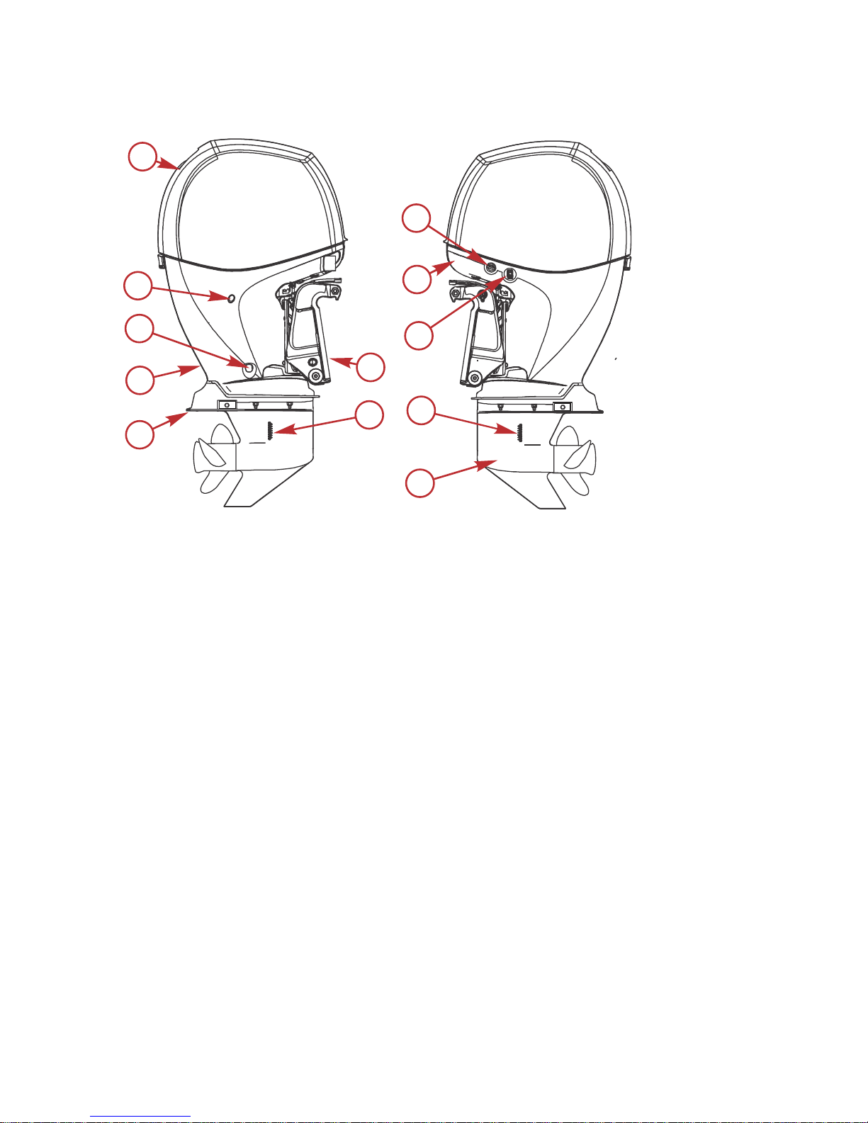
Component Identification
a - Top cowl
b - Engine flush
c - Bottom cowl
d - Auxiliary tilt switch
e - Transom brackets
f - Cooling water intake holes
g - Gearcase
h - Anti‑ventilation plate
i - Driveshaft housing
j - Engine oil drain
k - Water pump indicator hole
a
b
d
e
f
g
f
h
j
i
k
c
47824
GENERAL INFORMATION
20 eng
Page 31

Trailering Boat/Outboard
Trailer your boat with the outboard tilted down in a vertical operating position.
If additional ground clearance is required, the outboard should be tilted up
using an accessory outboard support device. Refer to your local dealer for
recommendations. Additional clearance may be required for railroad crossings,
driveways, and trailer bouncing.
47333
IMPORTANT: Do not rely on the power trim/tilt system or tilt support lever to
maintain proper ground clearance for trailering. The outboard tilt support lever
is not intended to support the outboard for trailering.
Shift the outboard to forward gear. This prevents the propeller from spinning
freely.
TRANSPORTING
eng 21
Page 32

Fuel Requirements
IMPORTANT: Use of improper gasoline can damage your engine. Engine
damage resulting from the use of improper gasoline is considered misuse
of the engine and will not be covered under the limited warranty.
FUEL RATINGS
Mercury outboard engines will operate satisfactorily with any major brand of
unleaded gasoline that meets the following specifications:
USA and Canada ‑ A posted pump octane rating of 87 (R+M)/2, minimum, for
most models. Premium gasoline 91 (R+M)/2 octane is also acceptable for most
models. Do not use leaded gasoline.
Outside USA and Canada ‑ A posted pump octane rating of 91 RON,
minimum, for most models. Premium gasoline (95 RON) is also acceptable for
all models. Do not use leaded gasoline.
USING REFORMULATED (OXYGENATED) GASOLINE (USA ONLY)
Reformulated gasoline is required in certain areas of the USA and is
acceptable for use in your Mercury Marine engine. The only oxygenate
currently in use in the USA is alcohol (ethanol, methanol, or butanol).
GASOLINE CONTAINING ALCOHOL
Bu16 Butanol Fuel Blends
Fuel blends of up to 16.1% butanol (Bu16) that meet the published Mercury
Marine fuel rating requirements are an acceptable substitute for unleaded
gasoline. Contact your boat manufacturer for specific recommendations on
your boat's fuel system components (fuel tanks, fuel lines, and fittings).
Methanol and Ethanol Fuel Blends
IMPORTANT: The fuel system components on your Mercury Marine engine will
withstand up to 10% alcohol (methanol or ethanol) content in the gasoline. Your
boat's fuel system may not be capable of withstanding the same percentage of
alcohol. Contact your boat manufacturer for specific recommendations on your
boat's fuel system components (fuel tanks, fuel lines, and fittings).
Be aware that gasoline containing methanol or ethanol may cause increased:
• Corrosion of metal parts
• Deterioration of rubber or plastic parts
• Fuel permeation through the rubber fuel lines
• Likelihood of phase separation (water and alcohol separating from the
gasoline in the fuel tank)
FUEL AND OIL
22 eng
Page 33

!
WARNING
Fuel leakage is a fire or explosion hazard, which can cause serious injury or
death. Periodically inspect all fuel system components for leaks, softening,
hardening, swelling, or corrosion, particularly after storage. Any sign of
leakage or deterioration requires replacement before further engine
operation.
IMPORTANT: If you use gasoline that contains or might contain methanol or
ethanol, you must increase the frequency of inspection for leaks and
abnormalities.
IMPORTANT: When operating a Mercury Marine engine on gasoline containing
methanol or ethanol, do not store the gasoline in the fuel tank for long periods.
Cars normally consume these blended fuels before they can absorb enough
moisture to cause trouble; boats often sit idle long enough for phase separation
to take place. Internal corrosion may occur during storage if alcohol has
washed protective oil films from internal components.
Fuel Additives
To minimize carbon deposit buildup in the engine, it is recommended to add
Mercury or Quicksilver Quickstor fuel stabilizer additive to the engine's fuel at
each tank fill throughout the boating season. Use additive as directed on
container.
Low Permeation Fuel Hose Requirement
Required for outboards manufactured for sale, sold, or offered for sale in the
United States.
• The Environmental Protection Agency (EPA) requires that any outboard
manufactured after January 1, 2009, must use low permeation fuel hose
for the primary fuel hose connecting the fuel tank to the outboard.
• Low permeation hose is USCG Type B1‑15 or Type A1‑15, defined as not
exceeding 15 g/m²/24 h with CE 10 fuel at 23 °C as specified in SAE J
1527 ‑ marine fuel hose.
Quick‑Disconnect Fuel Hose Fitting
!
WARNING
Fuel is flammable and explosive. Ensure that the key switch is off and the
lanyard is positioned so that the engine cannot start. Do not smoke or allow
sources of spark or open flame in the area while servicing. Keep the work
area well ventilated and avoid prolonged exposure to vapors. Always check
for leaks before attempting to start the engine, and wipe up any spilled fuel
immediately.
FUEL AND OIL
eng 23
Page 34

IMPORTANT: The fuel line quick‑disconnect fuel hose fitting is not equipped
with a check valve. Fuel will be present at the connection and may drain from
the hose when disconnected. Ensure there is a suitable container ready when
disconnecting the fuel line from the engine. Follow all fuel handling safety
precautions. Wipe up spilled fuel and dispose of according to local laws and
regulation.
53883
Quick-disconnect fuel hose fitting
EPA Pressurized Portable Fuel Tank Requirements
The Environmental Protection Agency (EPA) requires portable fuel systems
that are produced after January 1, 2011, for use with outboard engines to
remain fully sealed (pressurized) up to 34.4 kPa (5.0 psi). These tanks may
contain the following:
• An air inlet that opens to allow air to enter as the fuel is drawn out of the
tank.
• An air outlet that opens (vents) to the atmosphere if pressure exceeds
34.4 kPa (5.0 psi).
Fuel Demand Valve (FDV) Requirement
Whenever a pressurized fuel tank is used, a fuel demand valve is required to
be installed in the fuel hose between the fuel tank and the engine. The fuel
demand valve prevents pressurized fuel from entering the engine and causing
a fuel system overflow or possible fuel spillage.
FUEL AND OIL
24 eng
Page 35

The fuel demand valve has a manual release. The manual release can be used
(pushed in) to open (bypass) the valve in case of a fuel blockage in the valve.
a - Fuel demand valve ‑ installed in the
fuel hose between the fuel tank and
the engine
b - Manual release
c - Vent/water drain holes
Mercury Marine's Pressurized Portable Fuel Tank
Mercury Marine has created a new portable pressurized fuel tank that meets
the preceding EPA requirements. These fuel tanks are available as an
accessory or are provided with certain portable outboard models.
SPECIAL FEATURES OF THE PORTABLE FUEL TANK
• The fuel tank has a two‑way valve which allows air to enter the tank as
the fuel is drawn to the engine, and also opens to vent to the atmosphere
if internal pressure in the tank exceeds 34.4 kPa (5.0 psi). A hissing noise
may be heard as the tank vents to the atmosphere. This is normal.
• The fuel tank includes a fuel demand valve that prevents pressurized fuel
from entering the engine and causing a fuel system overflow or possible
fuel spillage.
• When installing the fuel tank cap, turn the cap to the right until you hear a
click. This signals that the fuel cap is fully seated. A built‑in device
prevents overtightening.
• The fuel tank has a manual vent screw which should be closed for
transportation and open for operation and cap removal.
Since sealed fuel tanks are not vented, they will expand and contract as the
fuel expands and contracts during heating and cooling cycles of the outside air.
This is normal.
REMOVING THE FUEL CAP
a - Fuel cap
b - Manual vent screw
c - Tab lock
IMPORTANT: Contents may be under pressure. Rotate the fuel cap 1/4 turn to
relieve pressure before opening.
a
c
b
46273
a
b
c
46290
FUEL AND OIL
eng 25
Page 36

1. Open the manual vent screw on top of the fuel cap.
2. Turn the fuel cap until it contacts the tab lock.
3. Press down on the tab lock. Rotate the fuel cap 1/4 turn to relieve the
pressure.
4. Press down on the tab lock again and remove the cap.
DIRECTIONS FOR USING THE PRESSURIZED PORTABLE FUEL TANK
1. When installing the fuel tank cap, turn the cap to the right until you hear a
click. This signals that the fuel cap is fully seated. A built‑in device
prevents overtightening.
2. Open the manual vent screw on top of the cap for operation and cap
removal. Close the manual vent screw for transportation.
3. For fuel hoses that have quick disconnects, disconnect the fuel line from
the engine or fuel tank when not in use.
4.
Follow Filling Fuel Tank instructions for fueling.
Filling Fuel Tank
!
WARNING
Avoid serious injury or death from a gasoline fire or explosion. Use caution
when filling fuel tanks. Always stop the engine and do not smoke or allow
open flames or sparks in the area while filling fuel tanks.
Fill the fuel tanks outdoors away from heat, sparks, and open flames.
Remove the portable fuel tanks from the boat to fill them.
Always stop the engine before filling the tanks.
Do not completely fill the fuel tanks. Leave approximately 10% of the tank
volume unfilled. Fuel will expand in volume as its temperature rises and can
leak under pressure if the tank is completely filled.
PORTABLE FUEL TANK PLACEMENT IN THE BOAT
Place the fuel tank in the boat so the vent is higher than the fuel level under
normal boat operating conditions.
Engine Oil Recommendations
Mercury or Quicksilver NMMA FC‑W or NMMA FC‑W catalyst compatible
certified SAE 10W‑30 Marine 4‑Stroke Engine Oil is recommended for general
all‑temperature use. As an optional choice, Mercury or Quicksilver SAE
25W‑40 Mineral Marine 4‑Stroke Engine Oil or SAE 25W‑40 Synthetic Blend
Marine 4‑Stroke engine oil may be used. If the recommended Mercury or
Quicksilver NMMA FC‑W certified oils are not available, a major outboard
manufacturer's brand of NMMA FC‑W certified 4‑Stroke outboard oil of similar
viscosity may be used.
FUEL AND OIL
26 eng
Page 37

IMPORTANT: The use of nondetergent oils, multiviscosity oils (other than
Mercury or Quicksilver NMMA FC‑W certified oil or a major brand NMMA FC‑W
certified oil), synthetic oils, low quality oils, or oils that contain solid additives
are not recommended.
58246
6.0 L (6.3 U.S. qt)
C
+100
+80
+60
+40
+20
0
+38
+27
+16
+4
-7
-18
F
+120
+49
25W-40
Engine Oil
10W-30
Checking and Adding Engine Oil
IMPORTANT: Do not overfill. Tilt outboard out/up past vertical for
approximately one minute to allow trapped oil to drain back to the oil sump. Tilt
outboard to vertical (not tilted) position when checking engine oil. For accurate
readings, check oil only when engine is cold or after engine has not run for at
least an hour.
1. Before starting (cold engine) tilt outboard out/up past vertical to allow
trapped oil to drain back to the oil sump. Allow outboard to remain tilted
for approximately one minute.
2. Tilt outboard to vertical operating position.
3.
Remove the top cowl. Refer to Maintenance ‑ Top Cowl Removal and
Installation.
4. Pull out the dipstick. Wipe the dipstick end with a clean rag or towel and
push it back in all the way.
5. Pull the dipstick back out again and observe the oil level. Oil should be in
the operating range (between the top bar and bottom bar).
FUEL AND OIL
eng 27
Page 38

IMPORTANT: Do not try to fill the oil level to the top bar. Oil level is correct as
long as it appears in the operating range (between the top bar and bottom
bar).
a - Oil level operating range
b - Top bar
c - Bottom bar
d - Upper 1/3 level
6. If the oil level is below the bottom bar, remove the oil filler cap and add
approximately 500 ml (16 oz) of the specified outboard motor oil. Allow a
few minutes for the oil to drain to the oil sump and recheck the dipstick. If
necessary, add additional oil to bring the oil level within the upper 1/3
level of the operating range. Avoid overfilling, do not try to fill the oil level
to the top bar.
47404
IMPORTANT: Inspect oil for signs of contamination. Oil contaminated with
water will have a milky color to it; oil contaminated with fuel will have a strong
fuel smell. If contaminated oil is noticed, have the engine checked by your
dealer.
7. Push the dipstick back in all the way.
a
47403
b
c
d
FUEL AND OIL
28 eng
Page 39

8. Install the oil fill cap hand‑tight.
9. Install the top cowl.
FUEL AND OIL
eng 29
Page 40

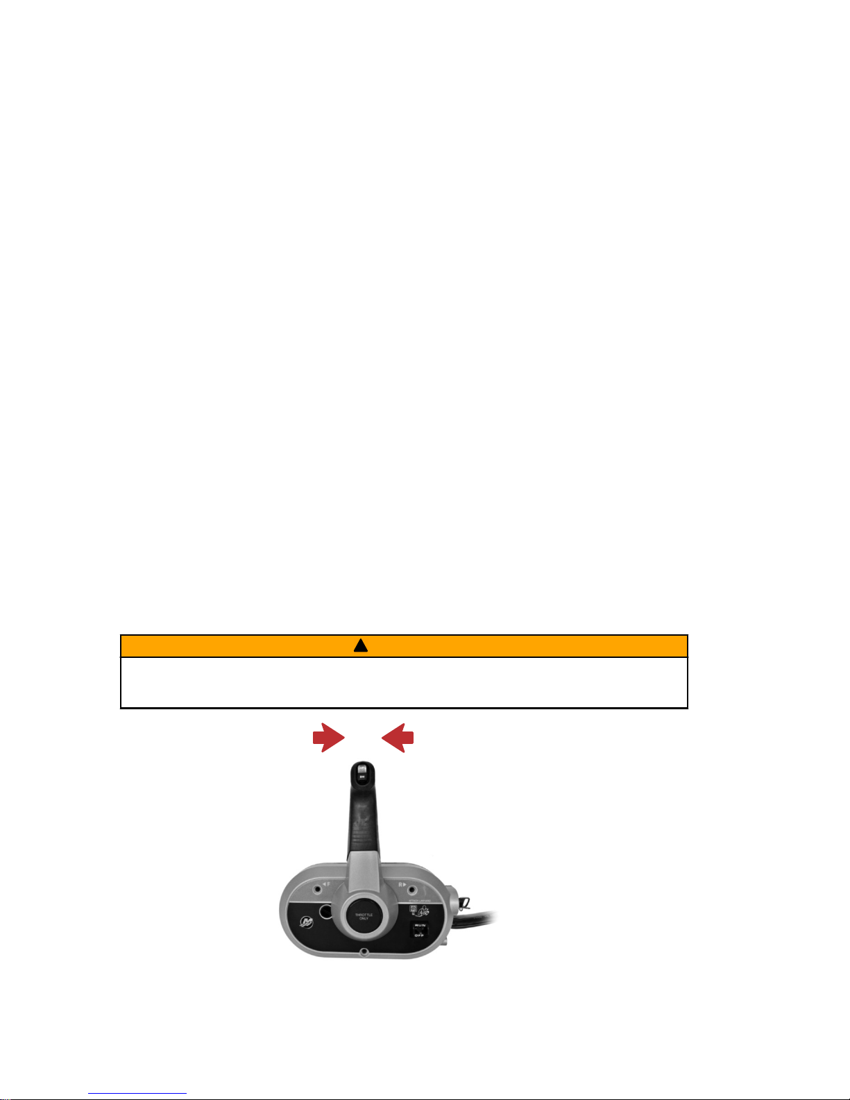
Remote Control Features
Your boat may be equipped with one of the Mercury Precision or Quicksilver
remote controls shown. If not, consult your dealer for a description of the
functions and operations of the remote control.
a -
Trim/tilt switch – Refer to Power Trim and Tilt
b - Ignition key switch – OFF, ON, START
c -
Throttle only button – Refer to Operation – Starting the Engine
d - Safety lanyard switch
Warning System
WARNING HORN SIGNALS
When the key switch is turned to the "ON" position, the horn will turn on for a
moment as a test to indicate the horn is working.
There are two types of warning horns to alert the operator of an active problem
within the engine’s operating system.
1.
Continuous six second beep: Indicates a critical engine condition.
Depending on the condition, the Engine Guardian system may engage
and protect the engine by limiting its power. You should return to port
immediately and contact your servicing dealer.
2.
Intermittent short beeps for six seconds: Indicates a noncritical engine
condition. This condition does not require immediate attention. You may
continue using your boat, however, depending on the nature of the
problem, the engine’s power may be limited by the Engine Guardian
system (see Engine Guardian System following) to protect the engine.
You should contact your servicing dealer at your earliest convenience.
aa
a
b
c
c
c
58240
d
FEATURES AND CONTROLS
30 eng
Page 41

It is important to note that in either of the above scenarios, the horn will only
sound one time. If you key the engine off and restart it, the horn will sound
again, one time, if the fault is still present. For visual display of the specific
engine functions and additional engine data, refer to SmartCraft Product
information, following.
A few of the noncritical conditions indicated by the intermittent short beeps for
six seconds can be corrected by the operator. These operator correctable
conditions are as follows:
• Water in the boat mounted water separating fuel filter (optional
accessory). Refer to the instructions supplied with the accessory kit.
• Cooling system (water pressure or engine temperature) problem. Stop the
engine and check the water intake holes in the lower unit for obstruction.
•
Low engine oil level. Refer to Fuel and Oil – Checking and Adding
Engine Oil.
ENGINE GUARDIAN SYSTEM
The Engine Guardian system monitors the critical sensors on the engine for
any early indications of problems. Engine Guardian is functional whenever your
engine is operating, so you never have to be concerned about whether or not
you are protected. The system will respond to a problem by sounding the
warning horn for six seconds and/or reducing engine power in order to provide
engine protection.
If Engine Guardian has been activated, reduce the engine speed. The problem
will need to be identified and corrected. The system must be reset before the
engine will operate at higher speeds. Moving the throttle lever back to the idle
position will reset the Engine Guardian system. If the Engine Guardian system
has determined the reset has not corrected the problem, Engine Guardian will
remain activated, limiting the throttle. The problem must be identified and
corrected before Engine Guardian will allow the engine to reach a normal
operating RPM.
OVERSPEED REV LIMIT
The overspeed rev limit is set at an RPM greater than the operating range. In
the event that the engine is operated at an RPM greater than or equal to the
overspeed limit, the PCM does not allow the engine to maintain the power
requested by the operator. Refer to Specifications to determine this engine’s
RPM limit.
Upon reaching the beginning of the rev limit, Engine Guardian will cut‑out the
ignition to specific cylinders. If the operator does not reduce engine speed,
Engine Guardian will cut‑out the ignition to all the cylinders. There is no audible
warning while Engine Guardian overspeed limit is active.
To reset the Engine Guardian protection:
1. Completely reduce the throttle for three seconds.
2. Engage the throttle. If the engine does not respond, repeat step one.
FEATURES AND CONTROLS
eng 31
Page 42

SMARTCRAFT PRODUCT
A Mercury SmartCraft System instrument package can be purchased for this
outboard. A few of the functions the instrument package will display are engine
RPM, coolant temperature, oil pressure, water pressure, battery voltage, fuel
consumption, and engine operating hours.
The SmartCraft instrument package will also aid in Engine Guardian
diagnostics. The SmartCraft Instrument package will display critical engine
alarm data and potential problems.
Power Trim and Tilt
The outboard has a trim/tilt control called power trim. This enables the operator
to easily adjust the position of the outboard by pressing the trim switch. Moving
the outboard in closer to the boat transom is called trimming in or down. Moving
the outboard further away from the boat transom is called trimming out or up.
The term trim generally refers to the adjustment of the outboard within the first
20° range of travel. This is the range used while operating the boat on plane.
The term tilt is generally used when referring to adjusting the outboard further
up out of the water. With the engine turned off and ignition switch turned on, the
outboard can be tilted out of the water. At low idle speed, the outboard can also
be tilted up past the trim range to permit, for example, shallow water operation.
a - Trim switch
b - Tilt range
c - Trim range
POWER TRIM OPERATION
With most boats, operating around the middle of the trim range will give
satisfactory results. However, to take full advantage of the trimming capability
there may be times when you choose to trim your outboard all the way in or
out. Along with an improvement in some performance aspects comes a greater
responsibility for the operator, and this is being aware of some potential control
hazards.
a
c
b
UP
DN
58238
FEATURES AND CONTROLS
32 eng
Page 43

The most significant control hazard is a pull or torque that can be felt on the
steering wheel or tiller handle. This steering torque results from the outboard
being trimmed so the propeller shaft is not parallel to the water surface.
!
WARNING
Trimming the outboard beyond a neutral steering condition may result in a
pull on the steering wheel or tiller handle and loss of boat control. Maintain
control of the boat if trimming beyond a neutral steering condition.
Consider the following lists carefully.
1. Trimming in or down can:
• Lower the bow
• Result in quicker planing off, especially with a heavy load or a stern
heavy boat
• Generally improve the ride in choppy water
• Increase steering torque or pull to the right (with the normal right‑hand
rotation propeller)
• In excess, can lower the bow of some boats to a point where they
begin to plow with their bow in the water while on plane. This can
result in an unexpected turn in either direction (called bow steering or
oversteering) if any turn is attempted, or if a significant wave is
encountered.
2. Trimming out or up can:
• Lift the bow higher out of the water
• Generally increase top speed
• Increase clearance over submerged objects or a shallow bottom
• Increase steering torque or pull to the left at a normal installation
height (with the normal right‑hand rotation propeller)
• In excess, can cause boat porpoising (bouncing) or propeller
ventilation
• Cause engine overheating if any cooling water intake holes are above
the waterline
TILTING OPERATION
To tilt outboard, shut off the engine and press the trim/tilt switch or auxiliary tilt
switch to the up position. The outboard will tilt up until the switch is released or
it reaches its maximum tilt position.
1. Engage the tilt support lever by rotating the knob to bring the support
lever upward.
2. Lower the outboard to rest on the tilt support lever.
FEATURES AND CONTROLS
eng 33
Page 44

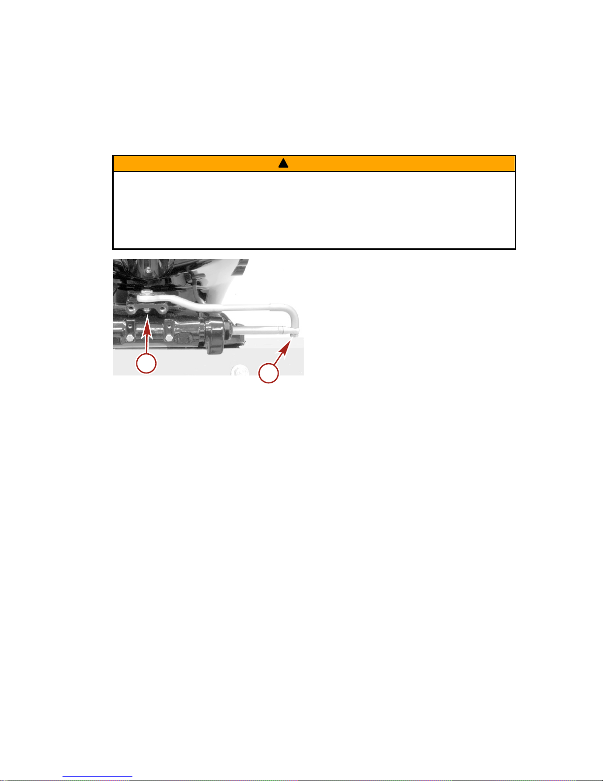
3. Disengage the tilt support lever by raising the outboard off the support
lever and rotating the lever down. Lower the outboard.
a - Tilt support lever
b - Knob
MANUAL TILTING
If the outboard cannot be tilted using the power trim/tilt switch, the outboard can
be manually tilted.
NOTE: The manual tilt release valve must be tightened before operating the
outboard to prevent the outboard from tilting up during reverse operation.
Turn out the manual tilt release valve three turns counterclockwise. This allows
manual tilting of the outboard. Tilt the outboard to the desired position and
tighten the manual tilt release valve.
47663
AUXILIARY TILT SWITCH
This switch can be used to tilt the outboard up or down using the power trim
system.
a - Auxiliary tilt switch
OPERATING IN SHALLOW WATER
When operating your boat in shallow water, you can tilt the outboard beyond
the maximum trim range to prevent hitting bottom.
a
b
47705
a
47704
FEATURES AND CONTROLS
34 eng
Page 45

NOTICE
Operating the engine with the outboard in the tilt range can damage the
engine or the transom. If operating the engine in the tilt range, such as in
shallow water, do not exceed 2000 RPM.
1. Reduce the engine speed below 2000 RPM.
2. Tilt the outboard up. Make sure all the cooling water intake holes stay
submerged at all times.
3. Operate the engine at slow speed only.
The outboard will remain at the selected tilt position, however, the engine RPM
will be limited.
Propeller Steering Torque—Trim Tab Adjustment
Propeller steering torque may cause your boat to pull in one direction. Steering
torque normally occurs at or above planing speeds. Higher speed causes
higher steering torque loads. The trim tab can compensate for normal steering
torque in many cases and can be adjusted within limits to reduce any unequal
steering effort.
26816
NOTE: Trim tab adjustment will have little effect reducing steering torque if the
outboard is installed with the antiventilation plate approximately 50 mm (2 in.)
or more above the boat bottom.
TRIM TAB ADJUSTMENT
Operate your boat at normal cruising speed and trim position. Turn the boat left
and right and note the direction the boat turns more easily.
If adjustment is necessary, loosen the trim tab fastener and make small
adjustments at a time. If the boat turns more easily to the left, move the trailing
edge of the trim tab to the left. If the boat turns more easily to the right, move
the trailing edge of the trim tab to the right. Tighten the fastener and test.
FEATURES AND CONTROLS
eng 35
Page 46

Important Daily Inspection Before Each Use
Any outboard mounted on the boat must have the mounting hardware
inspected and checked to ensure that the hardware has not become loose. A
decal on the transom bracket reminds the owner to check the fasteners
securing the outboard to the transom before each use.
51985
Decal on the transom bracket
Prestarting Check List
• Operator knows safe navigation, boating, and operating procedures.
• An approved personal flotation device of suitable size for each person
aboard and readily accessible (it is the law).
• A ring type life buoy or buoyant cushion designed to be thrown to a
person in the water.
• Know your boats' maximum load capacity. Look at the boat capacity plate.
• Fuel supply OK.
• Arrange passengers and load in the boat so the weight is distributed
evenly and everyone is seated in a proper seat.
• Tell someone where you are going and when you expect to return.
• It is illegal to operate a boat while under the influence of alcohol or drugs.
• Know the waters and area you will be boating; tides, currents, sand bars,
rocks, and other hazards.
•
Make inspection checks listed in Maintenance ‑ Inspection and
Maintenance Schedule.
OPERATION
36 eng
Page 47

Operating in Freezing Temperatures
When using your outboard or having your outboard moored in freezing or near
freezing temperatures, keep the outboard tilted down at all times so the
gearcase is submerged. This prevents the trapped water in the gearcase from
freezing and causing possible damage to the water pump and other
components.
If there is a chance of ice forming on the water, the outboard should be
removed and drained completely of water. If ice should form at the water level
inside the outboard driveshaft housing, it will block water flow to the engine
causing possible damage.
Operating in Saltwater or Polluted Water
We recommend that you flush the internal water passages of your outboard
with fresh water after each use in salt or polluted water. This will prevent a
buildup of deposits from clogging the water passages. Refer to Maintenance ‑
Flushing the Cooling System.
If you keep your boat moored in the water, always tilt the outboard so the
gearcase is completely out of water (except in freezing temperatures) when not
in use.
Wash the outboard exterior and flush out the exhaust outlet of the propeller and
gearcase with fresh water after each use. Each month, spray Mercury Precision
or Quicksilver Corrosion Guard on external metal surfaces. Do not spray on
corrosion control anodes as this will reduce the effectiveness of the anodes.
Operating at High Elevations
Your engine automatically compensates for high elevation changes. A different
pitch propeller may help reduce some normal performance loss resulting from
reduced oxygen in the air. Consult your dealer.
Effects of Elevation and Weather on Performance
The following conditions lower engine performance and cannot be
compensated by the engine fuel or electronic management systems:
• Above sea level elevations
• High temperature
• Low barometric pressure
• High humidity
These conditions above reduce air density to the engine, which in turn lowers
the following:
• Boost pressure on supercharged engines
• Horsepower and torque throughout the RPM range
• Peak RPM
• Cranking compression
OPERATION
eng 37
Page 48

EXAMPLE: An engine running at an elevation of 8,000 feet will have over a
30% power loss while a loss of engine power on a hot and humid day could be
as much as 14%. These losses apply to normally aspirated and supercharged
engines.
Compensating for power robbing conditions:
• Switch to lower pitch propeller.
• Change gear ratio.
Some boat performance can be improved by dropping to a lower pitch
propeller, but engine performance will still remain lower. In some cases, a gear
ratio reduction may be more beneficial. To optimize engine performance, prop
the engine to allow it to operate at or near the top end of the recommended
maximum RPM range at wide‑open throttle with a normal boat load.
Other advantages to propeller or gear ratio changes:
• Reduces the possibility of detonation
• Enhances overall reliability and durability of the engine
Setting Trim Angle while Running Engine at Idle Speed
a - Relief hole submerged
(wrong)
b - Relief hole above
waterline (correct)
Operating in Shallow Water
When operating your boat in shallow water, you can tilt the outboard beyond
the maximum trim range to prevent hitting bottom.
NOTICE
Operating the engine with the outboard in the tilt range can damage the
engine or the transom. If operating the engine in the tilt range, such as in
shallow water, do not exceed 2000 RPM.
1. Reduce the engine speed below 2000 RPM.
2. Tilt the outboard up. Make sure all the cooling water intake holes stay
submerged at all times.
3. Operate the engine at slow speed only.
The outboard will remain at the selected tilt position, however, the engine RPM
will be limited.
a
b
47821
OPERATION
38 eng
Page 49

Engine Break‑in Procedure
IMPORTANT: Failure to follow the engine break‑in procedures can result in
poor performance throughout the life of the engine and can cause engine
damage. Always follow break‑in procedures.
1. For the first two hours of operation, run the engine at varied throttle
settings up to 4500 RPM or at three‑quarter throttle, and at full throttle for
approximately one minute every ten minutes.
2. For the next eight hours of operation, avoid continuous operation at full
throttle for more than five minutes at a time.
Starting the Engine
Before starting, read the Prestarting Check List, and Engine Break‑in
Procedure in this section.
NOTICE
Without sufficient cooling water, the engine, the water pump, and other
components will overheat and suffer damage. Provide a sufficient supply of
water to the water inlets during operation.
1. Check the engine oil level.
20783
47820
2. Ensure the cooling water intake is submerged.
47412
OPERATION
eng 39
Page 50

3. Open the fuel tank vent screw (in filler cap) on manual venting type fuel
tanks.
19748
4.
Set the lanyard stop switch to the RUN position. Refer to General
Information ‑ Lanyard Stop Switch.
19791
5. Shift outboard to neutral (N) position.
N
58237
6. Ignition key starting ‑ Turn ignition key to the START position and release
the key. The electronic starting system will automatically crank the engine
for starting. If the engine fails to start, the engine will stop cranking. Turn
the key to the START position again until engine starts.
OPERATION
40 eng
Page 51

NOTE: For initial start of a new engine or for an engine that ran out of fuel or
was drained of fuel, the fuel system should be filled as follows:
Turn the ignition key switch to the ON position for approximately five seconds.
Turn the key to the START position and release it, the engine will crank for a
maximum of eight seconds. The engine may start, run rough, and stall while
filling the system. Repeat this starting procedure until the engine remains
running. Allow the starter motor to cool for 20–30 seconds between start
attempts.
19804
7. After the engine starts, check for a steady stream of water flowing out of
the water pump indicator hole.
IMPORTANT: If no water is coming out of the water pump indicator hole, stop
the engine and check the cooling water intake for obstruction. No obstruction
may indicate a water pump failure or blockage in the cooling system. These
conditions will cause the engine to overheat. Have the outboard checked by
your dealer. Operating the engine while overheated will cause engine damage.
8. If the engine does not start, push the throttle only button in and advance
the remote control handle slightly to open the throttle. Crank the engine
and be prepared to immediately reduce the throttle after the engine has
started.
N
58261
WARMING UP ENGINE
Before beginning operation, allow the engine to warm up at idling speed for
three minutes.
OPERATION
eng 41
Page 52

Gear Shifting
IMPORTANT: Observe the following:
•
Never shift the outboard into or out of gear unless the engine speed
is at idle. Shifting at higher than engine idle speed could cause
damage to the gearcase.
•
Do not shift the outboard into reverse when the forward motion of
the boat is greater than a no wake speed. Shifting into reverse at
higher boat speeds could cause the engine to stall, and in some
situations, this could cause water to be drawn into the cylinders,
resulting in severe engine damage.
•
Do not shift the outboard into reverse when the engine is not
running. Damage to the shift linkage could occur.
• The outboard has three gear shift positions: forward (F), neutral (N), and
reverse (R).
• When shifting, always stop at the neutral position and allow the engine
idle speed to stabilize before shifting into another gear.
• Always shift the outboard into gear with a quick motion.
• After shifting the outboard into gear, advance the lever further to increase
speed.
N
RF
58239
Stopping the Engine
Reduce the engine speed and shift the outboard to neutral position. Turn the
ignition key to "OFF" position.
26843
OFF
ON
START
OPERATION
42 eng
Page 53

Cleaning Care Recommendations
OUTBOARD CARE
To keep your outboard in the best operating condition, it is important that your
outboard receive the periodic inspections and maintenance listed in the
Inspection and Maintenance Schedule. We urge you to keep it maintained
properly to ensure the safety of you and your passengers, and retain its
dependability.
Record maintenance performed in the Maintenance Log at the back of this
book. Save all maintenance work orders and receipts.
Selecting Replacement Parts For Your Outboard
We recommend using original Mercury Precision or Quicksilver replacement
parts and Genuine Lubricants.
DO NOT USE CAUSTIC CLEANING CHEMICALS
IMPORTANT: Do not use caustic cleaning chemicals on the outboard power
package. Some cleaning products contain strong caustic agents such as hull
cleaners with hydrochloric acid. These cleaners can degrade some of the
components they come in contact with including critical steering fasteners.
Damage to steering fasteners may not be obvious during visual inspection and
this damage may lead to catastrophic failure. Some caustic cleaning chemicals
may cause or accelerate corrosion. Exercise caution when using cleaning
chemicals around the engine and follow the recommendations on the
packaging of the cleaning product.
CLEANING GAUGES
IMPORTANT: Never use high‑pressure water to clean gauges.
Routine cleaning of the gauges is recommended to prevent a buildup of salt
and other environmental debris. Crystalized salt can scratch the gauge display
lens when using a dry or damp cloth. Ensure that the cloth has a sufficient
amount of fresh water to dissolve and remove salt or mineral deposits. Do not
apply aggressive pressure on the display lens while cleaning.
When water marks cannot be removed with a damp cloth, mix a 50/50 solution
of warm water and isopropyl alcohol to clean the display lens. Do not use
acetone, mineral spirits, turpentine type solvents, or ammonia based cleaning
products. The use of strong solvents or detergents may damage the coating,
the plastics, or the rubber keys on the gauges. If the gauge has a sun cover
available, it is recommended that the cover be installed when the unit is not in
use to prevent UV damage to the plastic bezels and rubber keys.
CLEANING REMOTE CONTROLS
IMPORTANT: Never use high‑pressure water to clean remote controls.
MAINTENANCE
eng 43
Page 54

Routine cleaning of the remote control external surfaces is recommended to
prevent a buildup of salt and other environmental debris. Use a cloth towel
which has a sufficient amount of fresh water to dissolve and remove salt or
mineral deposits.
When water marks cannot be removed with a damp cloth, mix a 50/50 solution
of warm water and isopropyl alcohol to clean the remote control. Do not use
acetone, mineral spirits, turpentine type solvents, or ammonia based cleaning
products. The use of strong solvents or detergents may damage the coating,
the plastics, or the rubber components on the remote control.
CLEANING CARE FOR TOP AND BOTTOM COWLS
IMPORTANT: Dry wiping (wiping the plastic surface when it is dry) will result in
minor surface scratches. Always wet the surface before cleaning. Do not use
detergents containing hydrochloric acid. Follow the cleaning and waxing
procedure.
Cleaning and Waxing Procedure
1. Before washing, rinse the cowls with clean water to remove dirt and dust
that may scratch the surface.
2. Wash the cowls with clean water and a mild nonabrasive soap. Use a soft
clean cloth when washing.
3. Dry thoroughly with a soft clean cloth.
4. Wax the surface using a nonabrasive automotive polish (polish designed
for clear coat finishes). Remove the applied wax by hand using a clean
soft cloth.
5. To remove minor scratches, use Mercury Marine Cowl Finishing
Compound (92‑859026K 1).
CLEANING CARE FOR THE POWERHEAD (SALTWATER USE)
If the outboard is operated in saltwater, remove the top cowl and flywheel
cover. Inspect the powerhead and powerhead components for salt buildup.
Wash off any salt buildup from the powerhead and powerhead components
with fresh water. Keep water spray out of the air filter/intake and alternator.
After washing, allow the powerhead and components to dry. Apply Quicksilver
or Mercury Precision Lubricants Corrosion Guard spray on the external metal
surfaces of the powerhead and powerhead components. Do not allow the
Corrosion Guard spray to come in contact with the alternator drive belt or belt
pulleys.
IMPORTANT: Do not allow lubricant or Corrosion Guard spray to come in
contact with the alternator drive belt or the belt pulleys. The alternator drive belt
could slip and be damaged if it becomes coated with any lubricant or Corrosion
Guard spray.
MAINTENANCE
44 eng
Page 55

Tube Ref
No.
Description Where Used Part No.
120
Corrosion Guard
External metal surfaces of the powerhead
and powerhead components.
92-802878 55
EPA Emissions Regulations
All new outboards manufactured by Mercury Marine are certified to the United
States Environmental Protection Agency, as conforming to the requirements of
the regulations for the control of air pollution from new outboard motors. This
certification is contingent on certain adjustments set to factory standards. For
this reason, the factory procedure for servicing the product must be strictly
followed and, wherever practicable, returned to the original intent of the design.
Maintenance, replacement, or repair of the emission control devices and
systems may be performed by any marine spark ignition (SI) engine
repair establishment or individual.
EMISSION CERTIFICATION LABEL
An emission certification label, showing emission levels and engine
specifications directly related to emissions, is placed on the engine at the time
of manufacture.
a - Idle speed
b - Engine horsepower
c - Piston displacement
d - Engine power ‑ kilowatts
e - Date of manufacture
f - US EPA engine family name
g - Regulated emission limit for the engine family
h - Regulated emission limit for the engine family
i - Recommended spark plug and gap
j - Percent of fuel line permeation
OWNER RESPONSIBILITY
The owner/operator is required to have routine engine maintenance performed
to maintain emission levels within prescribed certification standards.
SPARK PLUG:
GAP:
EMISSION CONTROL
INFORMATION
THIS ENGINE CONFORMS TO
EMISSION REGULATIONS FOR SPARK IGNITION MARINE ENGINES
CALIFORNIA AND U.S. EPA
REFER TO OWNERS MANUAL FOR REQUIRED MAINTENANCE,
SPECIFICATIONS, AND ADJUSTMENTS
IDLE SPEED (in gear):
FAMILY:
HC+NOx:FEL:
LOW PERM/HIGH PERM:
g/kWh
hp
L
e
d
c
b
a
f
g
h
i
HC+NOx:FEL:
g/kWh
hp
L
CO FEL:
g/kWh
kw
g/kWh
j
43210
MAINTENANCE
eng 45
Page 56

The owner/operator is not to modify the engine in any manner that would alter
the horsepower or allow emission levels to exceed their predetermined factory
specifications.
Inspection and Maintenance Schedule
BEFORE EACH USE
•
Check engine oil level. Refer to Fuel and Oil ‑ Checking and Adding
Engine Oil.
• Check that lanyard stop switch stops the engine.
• Inspect the outboard for tightness to the boat transom. If any looseness of
the outboard or mounting fasteners exist, tighten the outboard mounting
fasteners to the specified torque. When looking for signs of looseness,
look for loss of outboard transom bracket material or paint caused by
movement between the outboard mounting fasteners and the outboard
transom brackets. Also look for signs of movement between the outboard
transom brackets and the boat transom (lift plate/setback bracket).
Description
Nm lb‑in. lb‑ft
Outboard mounting locknuts and
bolts ‑ standard boat transom
75 – 55.3
Outboard mounting locknuts and
bolts ‑ metal lift plates and setback
brackets
122 – 90
• Visually inspect the fuel system for deterioration or leaks.
• Check steering system for binding or loose components.
• Check propeller blades for damage.
• Inspect the hydraulic steering fittings and hoses for leaks or damage, if
equipped.
• Inspect the hydraulic steering fluid level, if equipped.
AFTER EACH USE
• Flush out the outboard cooling system if operating in salt, polluted, or
muddy water. Refer to Flushing the Cooling System.
• Wash off all salt deposits and flush out the exhaust outlet of the propeller
and gearcase with fresh water if operating in saltwater.
• If operating in saltwater, inspect the powerhead and powerhead
components for salt buildup. Refer to Cleaning Care for the Powerhead
(Saltwater Use).
EVERY 100 HOURS OF USE OR ONCE YEARLY, WHICHEVER
OCCURS FIRST
• Change engine oil and replace the oil filter. The oil should be changed
more often when the engine is operated under adverse conditions, such
as extended trolling. Refer to Changing Engine Oil.
MAINTENANCE
46 eng
Page 57

• Check low‑pressure fuel filter for contaminants. Replace filter if required.
Refer to Fuel System.
•
Remove the propeller and lubricate the propeller shaft. Refer to Propeller
Replacement.
• Inspect the condition of propeller bore sleeve when the propeller is
removed. Replace the propeller bore sleeve if it is suspected of being
worn, loose, or the retention tabs are broken—dealer service. Refer to
Propeller Bore Sleeve Inspection–If Equipped.
• Inspect the thermostat visually for corrosion or a broken spring. Ensure
the thermostat closes completely at room temperature—dealer service.
• Check the outboard mounting fasteners that fasten the outboard to the
boat transom. Tighten the fasteners to the specified torque—dealer
service.
Description
Nm lb‑in. lb‑ft
Outboard mounting locknuts and
bolts ‑ standard boat transom
75 – 55.3
Outboard mounting locknuts and
bolts ‑ metal lift plates and setback
brackets
122 – 90
• Check corrosion control anodes. Check more frequently when used in
saltwater. Refer to Corrosion Control Anode.
•
Drain and replace gearcase lubricant. Refer to Gearcase Lubrication.
•
Inspect battery. Refer to Battery Inspection.
• Saltwater usage: Remove and inspect spark plugs for corrosion and
replace as necessary. Apply Anti‑Seize Compound only on threads of
spark plug prior to installation. Refer to Spark Plug Inspection and
Replacement.
Tube Ref
No.
Description Where Used Part No.
81
Anti-Seize
Compound
Spark plug threads 92-898101389
• Check tightness of bolts, nuts, and other fasteners—dealer service.
• Add Quickleen to the fuel tank.
Tube Ref
No.
Description Where Used Part No.
Quickleen Engine &
Fuel System
Cleaner
Fuel tank 8M0047931
• Check cowl seals to ensure seals are intact and not damaged.
• Check internal cowl sound reduction foam to ensure foam is intact and not
damaged, if equipped.
MAINTENANCE
eng 47
Page 58

• Check that the intake silencer is in place, if equipped.
• Check that the idle relief muffler is in place, if equipped.
• Check for loose hose clamps and rubber boots on the air intake
assembly, if equipped.
EVERY 300 HOURS OF USE OR THREE YEARS
•
Check power trim fluid. Refer to Checking Power Trim Fluid.
• Lubricate all lubrication points. Lubricate more frequently when used in
saltwater. Refer to Lubrication Points.
•
Replace water pump impeller—dealer service.
1.
• Lubricate the splines on the upper driveshaft—dealer service.
• Check wiring and connectors—dealer service.
•
Replace alternator drive belt. Refer to Alternator Drive Belt Inspection
—dealer service.
• Replace the spark plugs.
BEFORE PERIODS OF STORAGE
•
Refer to Storage section.
Maintenance Schedule Decal (150 FourStroke)
The following table shows the icons and a general description of the
maintenance schedule decal located on the engine.
58260
1. Replace the water pump impeller more often if overheating occurs or reduced water pressure is noted.
MAINTENANCE
48 eng
Page 59

Icon Definition Icon Definition
58249
Replace
58250
Inspect
58251
Engine oil and filter
58252
Gearcase lubricant
58253
Spark plugs
58254
Thermostat
58255
Low pressure fuel filter
58256
Anodes
58257
Accessory drive belt
58258
Water pump impeller
Flushing the Cooling System
Flush the internal water passages of the outboard with fresh water after each
use in salt, polluted, or muddy water. This will help prevent a buildup of
deposits from clogging the internal water passages.
NOTE: The outboard can be tilted or in the vertical operating position during
flushing.
1. With the engine turned off, place the outboard in either the operating
position (vertical) or in a tilted position.
2. Remove the flush connector from the bottom cowl.
MAINTENANCE
eng 49
Page 60

3. Remove the cover from the flush connector and thread a water hose into
the flush connector.
47592
4. Turn on the water tap (½ maximum) and let the water flush through the
cooling system for about 15 minutes.
5. When flushing is complete, turn off the water and disconnect the water
hose.
6. Install the cover on the flush connector. Place the flush connector back
into the bottom cowl.
Top Cowl Removal and Installation
REMOVAL
Unlock the top cowl by pulling out on the rear cowl latch. Lift the top cowl off the
engine.
47632
INSTALLATION
1. Lower the top cowl over the engine.
MAINTENANCE
50 eng
Page 61

2. Bring the front of the cowl down first and engage the front cowl hook.
Lower the cowl into the seated position and apply pressure to the back of
the cowl to lock it in place. Ensure the cowl is securely fastened by trying
to pull up on the back of the cowl.
47633
Battery Inspection
The battery should be inspected at periodic intervals to ensure proper engine
starting capability.
IMPORTANT: Read the safety and maintenance instructions which accompany
your battery.
1. Turn off the engine before servicing the battery.
2. Ensure the battery is secure against movement.
3. Battery cable terminals should be clean, tight, and correctly installed.
Positive to positive and negative to negative.
4. Ensure the battery is equipped with a nonconductive shield to prevent
accidental shorting of battery terminals.
Fuel System
!
WARNING
Fuel is flammable and explosive. Ensure that the key switch is off and the
lanyard is positioned so that the engine cannot start. Do not smoke or allow
sources of spark or open flame in the area while servicing. Keep the work
area well ventilated and avoid prolonged exposure to vapors. Always check
for leaks before attempting to start the engine, and wipe up any spilled fuel
immediately.
IMPORTANT: Use an approved container to collect and store fuel. Wipe up
spilled fuel immediately. Material used to contain spilled fuel must be disposed
of in an approved receptacle.
Before servicing any part of the fuel system:
1. Stop engine and disconnect the battery.
2. Perform fuel system service in a well‑ventilated area.
MAINTENANCE
eng 51
Page 62

3. Inspect any completed service work for sign of fuel leakage.
FUEL LINE INSPECTION
Visually inspect the fuel line for cracks, swelling, leaks, hardness, or other signs
of deterioration or damage. If any of these conditions are found, the fuel line
must be replaced.
LOW-PRESSURE FUEL FILTER
The low‑pressure filter can be serviced as a general maintenance item,
however, the high‑pressure filter is under high pressure and should only be
serviced by an authorized dealer.
Removal
1. Turn the ignition key switch to the "OFF" position.
2. Move the lift handle so that the locking tab clears the bracket.
a - Lift handle
b - Locking tab secured under bracket
3. Use the lift handle and pull the fuel filter out of its opening. If necessary,
move the fuel hose so that it clears the bracket while lifting the fuel filter.
4. Push in on the fuel hose release tabs and disconnect the fuel hoses from
the fuel filter.
5. Place the lower hose into the hose holder to prevent it from dropping into
the filter hole.
47535
a
b
MAINTENANCE
52 eng
Page 63

6. Remove the fuel filter from the lift handle.
a - Fuel hose release tab
b - Low‑pressure fuel filter
c - Hose holder
Installation
1. Place the lift handle onto the fuel filter. Install the new fuel filter so the
arrow points towards the engine.
2. Connect the fuel hoses to the fuel filter securely with the locking hose
connections.
3. Visually inspect for fuel leakage from the fuel filter while turning the
ignition key to the "RUN" position, forcing fuel into the fuel filter. Repair
any fuel leaks if necessary.
4. Install the fuel filter back into the opening. Position the lift handle so that
the locking tab is secured under the bracket.
Corrosion Control Anode
The outboard has corrosion control anodes at different locations. An anode
helps protect the outboard against galvanic corrosion by sacrificing its metal to
be slowly eroded instead of the outboard metals.
Each anode requires periodic inspection, especially in saltwater which will
accelerate the erosion. To maintain this corrosion protection, always replace
the anode before it is completely eroded. Never paint or apply a protective
coating on the anode as this will reduce effectiveness of the anode.
a
b
47441
c
MAINTENANCE
eng 53
Page 64

Two anodes are located on each side of the gearcase. Another anode is
installed on the bottom of the transom bracket assembly.
47569
Propeller Bore Sleeve Inspection—If Equipped
The propeller bore sleeve is an important integral component of the gear
housing and should be inspected when the propeller is removed. The propeller
bore sleeve is designed to enhance engine characteristics and boat
performance by minimizing engine exhaust escaping between the outside of
the propeller and the gear housing. Exhaust gas mixing with the water over the
propeller blades, will cause a loss of engine and boat performance.
IMPORTANT: An authorized dealer should replace the propeller bore sleeve if
it is suspected of being worn, loose, or the retention tabs are broken.
a - Propeller bore sleeve
b - Gearcase oil fill screw
a
61978
b
MAINTENANCE
54 eng
Page 65

Propeller Replacement
!
WARNING
Rotating propellers can cause serious injury or death. Never operate the boat
out of the water with a propeller installed. Before installing or removing a
propeller, place the drive unit in neutral and engage the lanyard stop switch
to prevent the engine from starting. Place a block of wood between the
propeller blade and the anti‑ventilation plate.
1. Shift outboard to the neutral (N) position.
N
58237
2. Straighten the bent tabs on the propeller nut retainer.
3. Place a block of wood between the gearcase and the propeller to hold the
propeller and remove the propeller nut.
26901
4. Pull the propeller straight off the shaft. If the propeller is seized to the
shaft and cannot be removed, have the propeller removed by an
authorized dealer.
MAINTENANCE
eng 55
Page 66

5. Coat the propeller shaft with Extreme Grease or 2‑4‑C with PTFE.
47623
Tube Ref
No.
Description Where Used Part No.
Extreme Grease Propeller shaft 8M0071842
95
2-4-C with PTFE Propeller shaft 92-802859A 1
IMPORTANT: To prevent the propeller hub from corroding and seizing to the
propeller shaft, especially in saltwater, always apply a coat of the
recommended lubricant to the entire propeller shaft at the recommended
maintenance intervals and also each time the propeller is removed.
FLO-TORQ II PROPELLERS
1. Install the propeller onto the shaft with the supplied components as
shown.
2. Place the locknut retainer over the raised pins on the drive sleeve adapter
and tighten the locknut to the specified torque.
MAINTENANCE
56 eng
Page 67

3. Secure the locknut by bending the tabs up against the locknuts.
a - Forward thrust washer
b - Drive sleeve
c - Propeller
d - Drive sleeve adapter
e - Locknut retainer
f - Locknut
g - Raised pins
h - Tabs bent against the locknut
Description Nm lb‑in. lb‑ft
Propeller nut 75 – 55.3
FLO-TORQ IV PROPELLERS
1. Install the propeller onto the shaft with the supplied components as
shown.
2. Tighten the locknut to the specified torque.
45232
c
d
e
f
a
b
g
h
MAINTENANCE
eng 57
Page 68

3. Secure the locknut by bending three of the tabs into the grooves in the
drive sleeve adapter.
a - Forward thrust washer
b - Drive sleeve
c - Propeller
d - Drive sleeve adapter
e - Locknut retainer
f - Locknut
g - Tabs bent into grooves
Description Nm lb‑in. lb‑ft
Propeller nut 75 – 55.3
Spark Plug Inspection and Replacement
1. Remove the spark plug leads. Pull the rubber boots off the spark plugs.
47660
c
d
e
f
a
b
g
45248
MAINTENANCE
58 eng
Page 69

2. Remove the spark plugs to inspect.
47662
3. Replace the spark plug if the electrode is worn; the insulator is rough,
cracked, broken, or blistered; or if the precious metal is not visible on the
spark plug electrode.
IMPORTANT: The color of the plug may not accurately reflect its condition. To
accurately diagnose a faulty plug, inspect the precious metal on the plug's
electrode. If no precious metal is visible, replace the plug.
a - Precious metal
4.
Set the spark plug gap. Refer to Specifications.
27848
a
9381
MAINTENANCE
eng 59
Page 70

a. All of the spark plugs should have the gap checked and corrected as
necessary before installation.
b. Measure the gap with a feeler gauge or pin gauge. Never use a
wedge‑type gap checking tool to inspect or to adjust the gap.
c. If an adjustment is necessary, do not pry or apply any force on the
center electrode. This is critical with any type of spark plug that has a
wear surface, such as platinum or iridium added to either the ground
electrode or the center electrode.
d. When it is necessary to widen the gap, use a tool that only pulls back
on the ground electrode without touching the center electrode, the
porcelain, or the wear portion of the ground electrode.
e. When it is necessary to close the gap, gently tap the plug ground
electrode on a hard surface.
5. Saltwater use ‑ Apply a thin coating of Anti‑Seize Compound only on
threads of spark plugs.
Tube Ref
No.
Description Where Used Part No.
81
Anti-Seize
Compound
Spark plug threads 92-898101389
6. Before installing spark plugs, clean off any dirt on the spark plug seats.
Install the plugs finger‑tight and then tighten an additional 1/4 turn or
tighten to the specified torque.
Description
Nm lb‑in. lb‑ft
Spark plug 27 – 20
Fuse Replacement
IMPORTANT: Always carry spare fuses.
The electrical wiring circuits on the outboard are protected from overload by
fuses in the wiring. If a fuse is blown, try to locate and correct the cause of the
overload. If the cause is not found, the fuse may blow again.
MAINTENANCE
60 eng
Page 71

Open the fuse holder and look at the silver colored band inside the fuse. If the
band is broken, replace the fuse. Replace fuse with a new fuse with the same
rating.
a - Cover
b - Spare fuse holders
c - Fuse holder
d - Fuse 4 ‑ IGN. 20 amp ‑ ignition system
e - Fuse 2 ‑ FUEL 20 amp ‑ fuel delivery
f - Fuse 1 ‑ DIAG. 2 amp ‑ diagnostics/vessel (accessory) harness
g - Fuse 3 ‑ HELM 15 amp ‑ 14 pin remote control harness/cowl trim
switch
h - Good fuse
i - Blown fuse
h
i
47408
20
20
2
15
a
b
c
d
e
f
g
MAINTENANCE
eng 61
Page 72

Alternator Drive Belt Inspection
1. Remove the three screws that fastens the flywheel cover to the engine.
Lift the flywheel cover off the engine.
a - Flywheel cover
b - Screws (3)
2. Inspect the alternator drive belt.
a - Alternator drive belt
3. Have the belt replaced by an authorized dealer if any of the following
conditions are found:
• Cracks in the back of the belt or in the base of the V grooves.
• Excessive wear at the roots of the grooves.
• Rubber portion swollen by oil.
• Belt surfaces roughened.
• Signs of wear on edges or outer surfaces of belt.
4. Install the flywheel cover with three screws. Tighten the screws to the
specified torque.
Description
Nm lb‑in. lb‑ft
Flywheel cover screws 8 71 –
Lubrication Points
1. Lubricate the following with Extreme Grease or 2‑4‑C with PTFE.
47585
a
b
a
47588
MAINTENANCE
62 eng
Page 73

Tube Ref
No.
Description Where Used Part No.
Extreme Grease Propeller shaft 8M0071842
95
2-4-C with PTFE Propeller shaft 92-802859A 1
•
Propeller shaft ‑ Refer to Propeller Replacement for removal and
installation of the propeller. Coat the entire propeller shaft with
lubricant to prevent the propeller hub from corroding and seizing to the
shaft.
47623
2. Lubricate the following with 2‑4‑C with PTFE or Extreme Grease.
Tube Ref
No.
Description Where Used Part No.
95
2-4-C with PTFE Steering cable 92-802859A 1
Extreme Grease Steering cable 8M0071842
MAINTENANCE
eng 63
Page 74

• Steering cable grease fitting (if equipped) ‑ Rotate steering wheel to
fully retract the steering cable end into the outboard tilt tube. Lubricate
through fitting.
a - Fitting
b - Steering cable end
!
WARNING
Incorrect cable lubrication can cause hydraulic lock, leading to serious
injury or death from loss of boat control. Completely retract the end of the
steering cable before applying lubricant.
3. Lubricate the following with lightweight oil.
• Steering link rod pivot points ‑ Lubricate pivot points.
47652
b
a
47651
MAINTENANCE
64 eng
Page 75

Checking Power Trim Fluid
1. Tilt the outboard to the full up position and engage the tilt support lever.
47646
2. Remove the fill cap and check fluid level. The fluid level should be even
with the bottom of the fill hole. Add Quicksilver or Mercury Precision
Lubricants Power Trim and Steering Fluid. If not available, use automotive
automatic transmission fluid (ATF).
Tube Ref
No.
Description Where Used Part No.
114
Power Trim and
Steering Fluid
Power trim reservoir 92-858074K01
47647
Changing Engine Oil
ENGINE OIL CAPACITY
Engine oil capacity is approximately 6 liter (6.3 US qt).
IMPORTANT: Tilt the outboard out/up past vertical for approximately one
minute to allow any trapped oil to drain back to the oil sump.
OIL CHANGING PROCEDURE
1. Tilt the outboard out/up past vertical for approximately one minute to allow
any trapped oil to drain back to the oil sump.
2. Tilt the outboard to a vertical position.
MAINTENANCE
eng 65
Page 76

3. Use a 16 mm (5/8 in.) wrench and loosen the oil drain valve so that it can
be turned by hand. Be careful not to open the valve too far allowing oil to
drain.
4. Attach a 12 mm (7/16 in.) I.D. drain hose to the oil drain valve. Position
the opposite end of the hose into an appropriate container.
5. Loosen the oil drain valve 2‑1/2 turns to allow oil to drain. Do not exceed
2‑1/2 turns.
IMPORTANT: Do not loosen the oil drain valve more than 2‑1/2 turns out. The
oil seal could get damaged beyond 2‑1/2 turns.
6. After the oil has drained, hand‑tighten the oil drain valve (clockwise) and
remove the oil drain hose.
7. Tighten the oil drain valve to the specified torque. Clean up any oil in the
valve area.
Description
Nm lb‑in. lb‑ft
Oil drain valve 15 133 –
IMPORTANT: Overtightening the oil drain valve can damage the oil sump.
a - Oil drain valve
b - Drain hose
c - Loosen 2‑1/2 turns maximum
CHANGING OIL FILTER
1. Remove the plug from the oil trough and attach a 12 mm (7/16 in.) I.D.
drain hose to the fitting. Position the opposite end of the hose into an
appropriate container.
2. Unscrew the old filter by turning the filter to the left.
3. Allow oil in the trough to drain and remove the oil drain hose.
4. Clean any oil from the oil trough and install the plug.
b
48870
a
1
2
2-
c
MAINTENANCE
66 eng
Page 77

5. Clean the oil filter mounting base. Apply a film of clean oil to the filter
gasket. Do not use grease. Screw new filter on until gasket contacts base,
then tighten 3/4 to 1 turn.
a - Loosen
b - Oil filter
c - Oil trough
d - Drain hose
OIL FILLING
1. Remove the oil fill cap and add approximately 6 liters (6.3 US qt) of the
recommended oil. This will bring the oil level within the midpoint of the
operating range.
2. Idle engine for five minutes and check for leaks. Stop the engine. For an
accurate oil level reading, allow the engine to cool for at least an hour
before checking the oil level. Refer to Fuel and Oil ‑ Checking and
Adding Engine Oil.
NOTE: Checking the oil level within five minutes of engine shutdown can falsely
read up to 1 liter (1 US qt) low. Allow the engine to cool for at least an hour
before checking the oil level.
47404
a
c
d
b
47562
MAINTENANCE
eng 67
Page 78

Gearcase Lubrication
When adding or changing gearcase lubricant, visually check for the presence of
water in the lubricant. If water is present, it may have settled to the bottom and
will drain out prior to the lubricant, or it may be mixed with the lubricant, giving it
a milky colored appearance. If water is noticed, have the gearcase checked by
your dealer. Water in the lubricant may result in premature bearing failure or, in
freezing temperatures, will turn to ice and damage the gearcase.
Examine the drained gearcase lubricant for metal particles. A small amount of
metal particles indicates normal gear wear. An excessive amount of metal
filings or larger particles (chips) may indicate abnormal gear wear and should
be checked by an authorized dealer.
DRAINING GEARCASE
1. Place the outboard in a vertical operating position.
2.
Remove the propeller. Refer to Propeller Replacement.
3. Place the drain pan below the outboard.
4. Remove the vent plug and fill/drain plug and drain lubricant.
a - Vent plug
b - Fill/drain plug
GEARCASE LUBRICANT CAPACITY
Gearcase Lubricant Capacity (approximate)
Right‑hand rotation
830 ml (28.1 fl oz)
Left‑hand rotation
GEARCASE LUBRICANT RECOMMENDATION
Mercury or Quicksilver High Performance Gear Lubricant.
CHECKING LUBRICANT LEVEL AND REFILLING GEARCASE
1. Place the outboard in a vertical operating position.
2. Remove the vent plug/sealing washer.
a
b
22692
MAINTENANCE
68 eng
Page 79

3. Remove the fill/drain plug. Place the lubricant tube into the fill hole and
add the lubricant until it appears at the vent hole.
a - Vent hole
b - Fill hole
IMPORTANT: Replace the sealing washers if damaged.
4. Stop adding the lubricant. Install the vent plug and sealing washer before
removing the lubricant tube.
5. Remove the lubricant tube and install cleaned fill/drain plug and sealing
washer.
a
b
22693
MAINTENANCE
eng 69
Page 80

Storage Preparation
The major consideration in preparing your outboard for storage is to protect it
from rust, corrosion, and damage caused by freezing of trapped water.
The following storage procedures should be followed to prepare your outboard
for out of season storage or prolonged storage (two months or longer).
NOTICE
Without sufficient cooling water, the engine, the water pump, and other
components will overheat and suffer damage. Provide a sufficient supply of
water to the water inlets during operation.
FUEL SYSTEM
IMPORTANT: Gasoline containing alcohol (ethanol or methanol) can cause a
formation of acid during storage and can damage the fuel system. If the
gasoline being used contains alcohol, it is advisable to drain as much of the
remaining gasoline as possible from the fuel tank, remote fuel line, and engine
fuel system.
IMPORTANT: This outboard is equipped with a closed fuel system when the
engine is not running. With this closed system, fuel within the engine's fuel
system, other than the fuel tank, will remain stable during normal storage
periods without the addition of fuel treatment stabilizers.
Fill the fuel tank and engine fuel system with treated (stabilized) fuel to help
prevent formation of varnish and gum. Proceed with the following instructions.
• Portable fuel tank ‑ Pour the required amount of Quickstor Fuel Stabilizer
(follow instructions on container) into fuel tank. Tip fuel tank back and
forth to mix stabilizer with the fuel.
• Permanently installed fuel tank ‑ Pour the required amount of Quickstor
Fuel Stabilizer (follow instructions on container) into a separate container
and mix with approximately one liter (one quart) of gasoline. Pour this
mixture into fuel tank.
Tube Ref
No.
Description Where Used Part No.
124
Quickstor Fuel
Stabilizer
Fuel tank 92-8M0047932
Protecting External Outboard Components
• Touch up any paint nicks. See your dealer for touch‑up paint.
• Spray Quicksilver or Mercury Precision Lubricants Corrosion Guard on
external metal surfaces (except corrosion control anodes).
Tube Ref
No.
Description Where Used Part No.
120
Corrosion Guard External metal surfaces 92-802878 55
STORAGE
70 eng
Page 81

Protecting Internal Engine Components
IMPORTANT: Refer to Maintenance ‑ Spark Plug Inspection and Replacement
for correct procedure for removing spark plugs.
• Change the engine oil and filter.
• Remove the spark plugs.
• Spray approximately 30 ml (1 fl oz) of Storage Seal Rust Inhibitor into
each spark plug hole.
Tube Ref
No.
Description Where Used Part No.
119
Storage Seal Rust
Inhibitor
Spark plug holes 92-858081K03
• Actuate key/push button start switch to crank the engine through one start
cycle, which will distribute the storage seal throughout the cylinders.
• Install the spark plugs.
Gearcase
•
Drain and refill the gearcase lubricant (refer to Gearcase Lubricant).
Positioning Outboard for Storage
Store outboard in an upright (vertical) position to allow water to drain out of the
outboard.
NOTICE
Storing the outboard in a tilted position can damage the outboard. Water
trapped in the cooling passages or rain water collected in the propeller
exhaust outlet in the gearcase can freeze. Store the outboard in the full down
position.
Battery Storage
• Follow the battery manufacturer's instructions for storage and charging.
• Remove the battery from the boat and check water level. Charge if
necessary.
• Store the battery in a cool, dry place.
• Periodically check the water level and charge the battery during storage.
STORAGE
eng 71
Page 82

Starter Motor Will Not Crank the Engine
POSSIBLE CAUSES
• Lanyard stop switch not in RUN position.
• Blown 15‑amp fuse. Check 14‑pin remote control harness/cowl trim
switch/main power relay fuse. Refer to Maintenance section.
• Outboard is not shifted to neutral position.
• Weak battery or battery connections are loose or corroded.
• Ignition key switch failure.
• Wiring or electrical connection faulty.
• Starter motor solenoid or slave solenoid failure.
Engine Will Not Start
POSSIBLE CAUSES
•
Incorrect starting procedure. Refer to Operation section.
• Old or contaminated gasoline.
• Fuel is not reaching the engine.
• Fuel tank is empty.
• Fuel tank vent not open or restricted.
• Fuel line is disconnected or kinked.
•
Fuel filter is obstructed. Refer to Maintenance section.
• Fuel pump failure.
• Fuel tank filter obstructed.
• Ignition system component failure.
•
Spark plugs fouled or defective. Refer to Maintenance section.
Engine Runs Erratically
POSSIBLE CAUSES
• Overheating ‑ Warning horn not working.
• Low oil pressure. Check oil level.
•
Spark plugs fouled or defective. Refer to Maintenance section.
• Incorrect setup and adjustments.
• Fuel is being restricted to the engine.
a.
Engine fuel filter is obstructed. Refer to Maintenance section.
b. Fuel tank filter obstructed.
c. Stuck antisiphon valve located on permanently built‑in type fuel tanks.
d. Fuel line is kinked or pinched.
• Fuel pump failure.
TROUBLESHOOTING
72 eng
Page 83

• Ignition system component failure.
Performance Loss
POSSIBLE CAUSES
• Overheating ‑ Warning horn not working.
• Low oil pressure. Check oil level.
• Throttle not opening fully.
• Damaged propeller or improper propeller size.
• Incorrect engine timing, adjustment, or setup.
• Boat overloaded or load improperly distributed.
• Excessive water in bilge.
• Boat bottom is dirty or damaged.
Battery Will Not Hold Charge
POSSIBLE CAUSES
• Battery connections are loose or corroded.
• Low electrolyte level in battery.
• Worn out or inefficient battery.
• Excessive use of electrical accessories.
• Defective rectifier, alternator, or voltage regulator.
• Open circuit in the alternator output wire (fused link).
TROUBLESHOOTING
eng 73
Page 84

Service Assistance
LOCAL REPAIR SERVICE
If you need service for your Mercury‑outboard‑powered boat, take it to your
authorized dealer. Only authorized dealers specialize in Mercury products and
have factory‑trained mechanics, special tools and equipment, and genuine
Quicksilver parts and accessories to properly service your engine.
NOTE: Quicksilver parts and accessories are engineered and built by Mercury
Marine specifically for your power package.
SERVICE AWAY FROM HOME
If you are away from your local dealer and the need arises for service, contact
the nearest authorized dealer. If, for any reason, you cannot obtain service,
contact the nearest Regional Service Center. Outside the United States and
Canada, contact the nearest Marine Power International Service Center.
STOLEN POWER PACKAGE
If your power package is stolen, immediately advise the local authorities and
Mercury Marine of the model and serial numbers and to whom the recovery is
to be reported. This information is maintained in a database at Mercury Marine
to aid authorities and dealers in the recovery of stolen power packages.
ATTENTION REQUIRED AFTER SUBMERSION
1. Before recovery, contact an authorized Mercury dealer.
2. After recovery, immediate service by an authorized Mercury dealer is
required to reduce the possibility of serious engine damage.
REPLACEMENT SERVICE PARTS
!
WARNING
Avoid fire or explosion hazard. Electrical, ignition, and fuel system
components on Mercury Marine products comply with federal and
international standards to minimize risk of fire or explosion. Do not use
replacement electrical or fuel system components that do not comply with
these standards. When servicing the electrical and fuel systems, properly
install and tighten all components.
Marine engines are expected to operate at or near full throttle for most of their
lives. They are also expected to operate in both fresh and saltwater
environments. These conditions require numerous special parts.
PARTS AND ACCESSORIES INQUIRIES
Direct any inquiries concerning genuine Mercury Precision Parts® or
Quicksilver Marine Parts and Accessories® to a local authorized dealer.
Dealers have the proper systems to order parts and accessories, if they are not
in stock. Engine model and serial number are required to order correct parts.
OWNER SERVICE ASSISTANCE
74 eng
Page 85

RESOLVING A PROBLEM
Satisfaction with your Mercury product is important to your dealer and to us. If
you ever have a problem, question or concern about your power package,
contact your dealer or any authorized Mercury dealership. If you need
additional assistance:
1. Talk with the dealership's sales manager or service manager.
2. If your question, concern, or problem cannot be resolved by your
dealership, please contact the Mercury Marine Service Office for
assistance. Mercury Marine will work with you and your dealership to
resolve all problems.
The following information will be needed by the Customer Service:
• Your name and address
• Your daytime telephone number
• The model and serial numbers of your power package
• The name and address of your dealership
• The nature of the problem
CONTACT INFORMATION FOR MERCURY MARINE CUSTOMER
SERVICE
For assistance, call, fax, or write to the geographic office in your area. Please
include your daytime telephone number with mail and fax correspondence.
United States, Canada
Telephone
English +1 920 929 5040
Français +1 905 636 4751
Mercury Marine
W6250 Pioneer Road
P.O. Box 1939
Fond du Lac, WI 54936-1939
Fax
English +1 920 929 5893
Français +1 905 636 1704
Website www.mercurymarine.com
Australia, Pacific
Telephone +61 3 9791 5822 Brunswick Asia Pacific Group
41–71 Bessemer Drive
Dandenong South, Victoria 3175
Australia
Fax +61 3 9706 7228
Europe, Middle East, Africa
Telephone +32 87 32 32 11 Brunswick Marine Europe
Parc Industriel de Petit-Rechain
B-4800 Verviers,
Belgium
Fax +32 87 31 19 65
OWNER SERVICE ASSISTANCE
eng 75
Page 86

Mexico, Central America, South America, Caribbean
Telephone +1 954 744 3500 Mercury Marine
11650 Interchange Circle North
Miramar, FL 33025
U.S.A.
Fax +1 954 744 3535
Japan
Telephone +072 233 8888 Kisaka Co., Ltd.
4‑130 Kannabecho, Sakai‑ku
Sakai‑shi, Osaka 590‑0984, Japan
Fax +072 233 8833
Asia, Singapore
Telephone +65 65466160 Brunswick Asia Pacific Group
T/A Mercury Marine Singapore Pte Ltd
29 Loyang Drive
Singapore, 508944
Fax +65 65467789
Ordering Literature
Before ordering literature, have the following information about your power
package available:
Model
Serial Number
Horsepower Year
UNITED STATES AND CANADA
For additional literature for your Mercury Marine power package, contact your
nearest Mercury Marine dealer or contact:
Mercury Marine
Telephone Fax Mail
(920) 929‑5110
(USA only)
(920) 929‑4894
(USA only)
Mercury Marine
Attn: Publications Department
P.O. Box 1939
Fond du Lac, WI 54936-1939
OUTSIDE THE UNITED STATES AND CANADA
Contact your nearest Mercury Marine authorized service center to order
additional literature that is available for your particular power package.
OWNER SERVICE ASSISTANCE
76 eng
Page 87

Submit the following
order form with payment
to:
Mercury Marine
Attn: Publications Department
W6250 Pioneer Road
P.O. Box 1939
Fond du Lac, WI 54936-1939
Ship To: (Copy this form and print or type–This is your shipping label)
Name
Address
City, State, Province
ZIP or postal code
Country
Quantity Item Stock Number Price Total
. .
. .
. .
. .
. .
Total Due .
OWNER SERVICE ASSISTANCE
eng 77
Page 88

Mercury Marine Validated Engine Mounting Hardware
IMPORTANT: Mercury Marine provides validated fasteners and installation
instructions, including torque specifications, with all of our outboards so they
can be properly secured to boat transoms. Improper installation of the outboard
can cause performance and reliability issues that can lead to safety concerns.
Follow all of the instructions relating to the outboard installation. DO NOT
mount any other accessory onto the boat with the fasteners provided with the
outboard. For example, do not mount tow sport bars or boarding ladders onto
the boat using the mounting hardware included with the outboard. Installing
other products onto the boat that utilize the outboard mounting hardware will
compromise the ability of that hardware to properly and safely secure the
outboard to the transom.
Outboards that require validated mounting hardware will have the following
decal on the transom clamp.
51965
Accessories Mounted to the Transom Clamp Bracket
Mercury Marine has been made aware that certain aftermarket marine
accessories, such as emergency boarding ladders, shallow water anchors,
transom wedge kits, and tow sport attaching devices, have been mounted to
the boat by use of the same fasteners that secure the outboard to the transom
or jack plate. Using the same fastener to secure both an accessory and the
engine to the boat compromises the ability of the fasteners to maintain the
proper clamp load. A boat with loose engine mounting fasteners creates the
possibility of performance, durability, and safety issues.
OUTBOARD INSTALLATION
78 eng
Page 89

!
WARNING
Avoid serious injury or death resulting from a loss of boat control. Loose
engine fasteners could cause the transom bracket to fail, resulting in a loss of
the driver's ability to control the boat. Always ensure that the engine
fasteners are tightened to the specified torque.
ACCEPTABLE ACCESSORY MOUNTING TO THE TRANSOM CLAMP
BRACKET
After the engine is mounted to the transom or jack plate in accordance with the
engine installation instructions, it is acceptable to attach an accessory to the
boat by use of the unused bolt holes in the transom clamp bracket as shown in
Figure 1.
The following list provides additional guidelines for mounting accessories to the
transom clamp bracket.
• The accessory fasteners must pass through the boat transom or jack
plate.
OUTBOARD INSTALLATION
eng 79
Page 90

• The installation must not create interference issues, as would an
accessory mounting plate resting in the radius of the transom clamp
bracket. Refer to Figure 1.
Figure 1
a - Minimum clearance 3.175 mm (0.125 in.)
b - Edge of accessory bracket
c - Transom clamp bracket wall
d - Radius
e - Engine supplied mounting fasteners
f - Fasteners supplied by the accessory manufacturer installed through
unused engine mounting bracket holes
b
c
d
a
f
54624
e
OUTBOARD INSTALLATION
80 eng
Page 91

UNACCEPTABLE ACCESSORY MOUNTING
IMPORTANT: Do not use the fasteners that secure the engine to the boat
(either the transom or the jack plate) for any purpose other than securing the
engine to the boat.
1. Do not mount an accessory to the transom clamp bracket in an
unsupported condition. Refer to Figure 2.
54625
Figure 2
2. Do not attach an accessory to the boat by use of the engine mounting
hardware. Refer to Figure 3.
Figure 3
a - Engine supplied mounting
fasteners
b - Transom clamp bracket
c - Accessory
53523
a
b
c
OUTBOARD INSTALLATION
eng 81
Page 92

3. Do not install wedges or plates between the transom clamp brackets and
the transom (or jack plate). Refer to Figure 4.
Figure 4
a - Boat transom or jack plate
b - Transom clamp bracket
c - Wedge/plate
Important Information
Rigging boats, which includes proper engine installation has become more
complex over the years. As a result, Mercury Marine recommends that engines
be installed only by Mercury authorized dealers. If you intend to disregard this
recommendation, and install the engine yourself, please make sure to read and
comply with these instructions. Failure to comply with these installation
instructions could lead to serious injury or death.
NOTE: Do not install an accessory electric fuel pump onto the fuel system for
this engine.
Boat Horsepower Capacity
!
WARNING
Exceeding the boat's maximum horsepower rating can cause serious injury
or death. Overpowering the boat can affect boat control and flotation
characteristics or break the transom. Do not install an engine that exceeds
the boat's maximum power rating.
54058
a
b
c
OUTBOARD INSTALLATION
82 eng
Page 93

Do not overpower or overload your boat. Most boats will carry a required
capacity plate indicating the maximum acceptable power and load as
determined by the manufacturer following certain federal guidelines. If in doubt,
contact your dealer or the boat manufacturer.
U.S. COAST GUARD CAP ACITY
MAXIMUM HORSEPOWER XXX
MAXIMUM PERSON
CAPACITY (POUNDS)
XXX
MAXIMUM WEIGHT
CAPACITY
XXX
26777
Start in Gear Protection
!
WARNING
Starting the engine with the drive in gear can cause serious injury or death.
Never operate a boat that does not have a neutral‑safety‑protection device.
The remote control connected to the outboard must be equipped with a start in
neutral only protection device. This prevents the engine from starting in gear.
Fuel System
ACCESSORY ELECTRIC FUEL PUMP
IMPORTANT: Do not install an accessory electric fuel pump onto the fuel
system for this engine.
AVOIDING FUEL FLOW RESTRICTION
IMPORTANT: Adding components to the fuel supply system (filters, valves,
fittings, etc.) may restrict the fuel flow. This may cause engine stalling at low
speed, and/or a lean fuel condition at high RPM that could cause engine
damage.
LOW PERMEATION FUEL HOSE REQUIREMENT
Required for outboards manufactured for sale, sold, or offered for sale in the
United States.
• The Environmental Protection Agency (EPA) requires that any outboard
manufactured after January 1, 2009, must use low permeation fuel hose
for the primary fuel hose connecting the fuel tank to the outboard.
• Low permeation hose is USCG Type B1‑15 or Type A1‑15, defined as not
exceeding 15 g/m²/24 h with CE 10 fuel at 23 °C as specified in SAE J
1527 ‑ marine fuel hose.
OUTBOARD INSTALLATION
eng 83
Page 94

EPA PRESSURIZED PORTABLE FUEL TANK REQUIREMENTS
The Environmental Protection Agency (EPA) requires portable fuel systems
that are produced after January 1, 2011, for use with outboard engines to
remain fully sealed (pressurized) up to 34.4 kPa (5.0 psi). These tanks may
contain the following:
• An air inlet that opens to allow air to enter as the fuel is drawn out of the
tank.
• An air outlet that opens (vents) to the atmosphere if pressure exceeds
34.4 kPa (5.0 psi).
FUEL DEMAND VALVE (FDV) REQUIREMENT
Whenever a pressurized fuel tank is used, a fuel demand valve is required to
be installed in the fuel hose between the fuel tank and the engine. The fuel
demand valve prevents pressurized fuel from entering the engine and causing
a fuel system overflow or possible fuel spillage.
The fuel demand valve has a manual release. The manual release can be used
(pushed in) to open (bypass) the valve in case of a fuel blockage in the valve.
a - Fuel demand valve ‑ installed in the
fuel hose between the fuel tank and
the engine
b - Manual release
c - Vent/water drain holes
FUEL TANKS
Portable Fuel Tank
Select a suitable location in the boat within the engine fuel line length
limitations and secure the tank in place.
Permanent Fuel Tank
Permanent fuel tanks should be installed in accordance with industry and
federal safety standards, which include recommendations applicable to
grounding, antisiphon protection, ventilation, etc.
FUEL SUPPLY MODULE PRIMING PROCEDURE
The fuel supply module (FSM) is not vented to the ambient air. The air trapped
in the FSM, fuel lines, and fuel rail, will be slightly compressed during the initial
ignition key on with a dry or drained fuel system. Additional key on events
under these conditions, will not compress the air further to finish the priming of
the FSM. Excessive number of key on events may eventually damage the fuel
pumps. The volume of air trapped in the FSM must be purged to prime the fuel
system. This can be achieved by connecting a tool to the fuel rail Schrader
valve fitting to quickly purge the system into an approved container, or by
cranking the engine.
a
c
b
46273
OUTBOARD INSTALLATION
84 eng
Page 95

Priming the FSM with a Fuel Pressure Gauge
The use of a purge tool for priming the FSM is the preferred method, but is not
always practical. The objective is to purge the air entrained in the fuel system
through a purge tool connected to the fuel rail Schrader valve test port. During
the key on, opening the dump valve will allow the air to be purged from the
FSM and fuel rail. This method should be used on vessels where the fuel inlet
system to the outboard is restrictive; contains an antisiphon valve or holds a
relatively large volume of fuel because of a long fuel supply line or water
separating fuel filter. If a primer bulb is installed, it can be used during the
priming event to shorten the amount of time required to start the engine.
1. Verify the engine is in a level vertical position.
2. Verify the vessel fuel supply line is connected to the outboard fuel system
inlet fitting.
3. Connect a fuel pressure gauge to the fuel rail Schrader valve.
Fuel Pressure Gauge Kit 91‑881833A03
2807
Tests the fuel pump pressure; can be
used to relieve fuel pressure.
OUTBOARD INSTALLATION
eng 85
Page 96

4. Secure the fuel pressure gauge purge hose into an appropriate fuel
container to collect excess fuel.
a - Fuel pressure gauge purge valve
b - Schrader valve
c - Purge hose to appropriate container
5. Open the fuel pressure gauge purge valve and turn the ignition key on.
The fuel pumps will run for approximately three to five seconds.
6. Turn the ignition key off and then on. The fuel pumps will run for
approximately three to five seconds. Continue this ignition key cycle until
the purged fuel is relatively clear of air bubbles.
NOTE: If the outboard fuel system does not prime within 15 key on events,
check for leaks in the fuel supply line to the outboard. Repair as needed. If no
leak is found, the fuel supply system to the outboard may be too restrictive.
Correct the condition and try again.
7. Remove the fuel pressure gauge.
8. Turn the ignition key on. When the fuel pumps stop running, start the
engine. The engine may not start on the first attempt. The engine will run
rough at idle for up to two minutes while the residual air is purged from the
fuel system.
a
b
c
58370
OUTBOARD INSTALLATION
86 eng
Page 97

Priming the FSM (Ran out of Fuel Condition)
The use of a purge tool for priming the FSM is the preferred method, but is not
always practical. When the vessel fuel system is void of fuel volume, it can be
primed without the use of a purge tool. The objective is to purge the air
entrained in the fuel system through the fuel injectors during engine cranking to
allow fuel to enter the fuel module. This method can be used on vessels where
the fuel inlet system to the outboard is less restrictive and holds a relatively
small volume of fuel; a short fuel supply line, no water separating fuel filter, or a
water separating fuel filter is already primed. If a primer bulb is installed, it can
be used during the priming event to shorten the amount of time required to start
the engine.
1. Verify the engine is in a level vertical position.
2. Verify the vessel fuel supply line is connected to the outboard fuel system
inlet fitting.
3. Turn the ignition key on. The fuel pumps will run for approximately three
to five seconds.
4. Turn the ignition key to the start position and release the key. The ECM
controls the activation of the starter. The starter may continue cranking for
up to eight seconds.
NOTE: When priming a drained fuel system, residual fuel may cause the
engine to flare and stall which shortens the engine cranking event.
5. Continue with the ignition key on and start sequence until the engine
continues to run.
IMPORTANT: Allow the starter motor to cool for 20 to 30 seconds between full
eight second crank events. Limit the number of events to a maximum of 10 full
eight second cranking events.
6. After the engine starts, it may run rough at idle for up to two minutes while
the residual air is purged from the fuel system.
7. If the fuel system will not prime within 10 full eight second cranking
events, use the previous procedure Priming the FSM with a Fuel
Pressure Gauge to prime the fuel system.
OUTBOARD INSTALLATION
eng 87
Page 98

Installation Specifications
a - Minimum transom opening
b - Engine centerline for dual engine ‑ 66.0 cm (26 in.)
Minimum Transom Opening
Single engine 84.2 cm (33 in.)
Dual engine 149.9 cm (59 in.)
Lifting Outboard
1. Remove the top cowl.
2. Install the lifting base to the flywheel using three bolts. Tighten the bolts
securely.
3. Thread the lifting eye into the lifting base.
4. Connect a hoist that has a minimum lift capacity of 450 kg (1000 lb) to the
lifting eye.
5. Lift the outboard and place it on the transom.
a - Lifting base
b - Lifting eye
18552
a
a
b
a
b
47706
OUTBOARD INSTALLATION
88 eng
Page 99

Flywheel Puller/Lifting Ring 91‑895343T02
14869
Removes flywheel from engine. Used
for lifting powerhead/engine.
Shipping Bracket Removal
1. Remove the two top screws and loosen the two bottom screws.
2. Slide the shipping bracket off the bottom screws.
3. Tighten the bottom screws to the specified torque.
a - Shipping bracket
b - Top screws
c - Bottom screws
Description Nm lb‑in. lb‑ft
Bottom screws 7.9 70 –
c
b
c
a
47720
OUTBOARD INSTALLATION
eng 89
Page 100

Steering Cable ‑ Starboard Side Routed Cable
1. Lubricate O‑ring seal and entire cable end.
3724
95
Tube Ref
No.
Description Where Used Part No.
95
2-4-C with PTFE O-ring seal and entire cable end 92-802859A 1
2. Insert steering cable into tilt tube.
3. Tighten the nut to the specified torque.
47708
Description
Nm lb‑in. lb‑ft
Nut 47.5 – 35
Steering Link Rod Fasteners (if equipped)
IMPORTANT: The steering link rod that connects the steering cable to the
engine must be fastened using a special washer head bolt ("a" ‑ Part Number
10‑856680) and self‑locking nylon insert locknuts ("c" and "d" ‑ Part Number
11‑826709113). These locknuts must never be replaced with common nuts
(nonlocking) as they will work loose and vibrate off, freeing the link rod to
disengage.
OUTBOARD INSTALLATION
90 eng
 Loading...