

Page 1
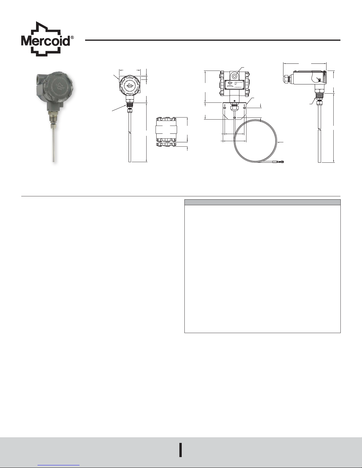
Series CRF2 Capacitive Level Transmitter
2X 1/2 FEMALE
NPT
CONNECTION
3/4 MALE
NPT
CONNECTION
9/16
2X 1/2 FEMALE NPT
4-7/16
[1
6
By Dwyer
Specications - Installation and Operating Instructions
Bulletin L-36
[14.29]
3-19/32
CONDUIT
PROCESS
The Series CRF2 Capacitive Level Transmitter is a level transmitter providing a two-
wire 4 to 20 mA output to indicate level of liquids, powders and bulk materials. State of
the art sensing technology in the CRF2, using impulse RF admittance measurement
provides excellent accuracy and stability. The CRF2 senses capacitance changes
resulting from the height of the material in the tank between the probe and the tank
wall. In non-metallic tanks or tanks that do not have the wall parallel to the probe a
ground reference must be used.
The CRF2 comes with either a rigid or exible probe depending on application
installation need and probe length required. Featured in the CRF2 is easy push button
calibration of zero and span. Custom order the CRF2 to any length probe that you
need for your application. FEP covered probe is ideal for use with corrosive media.
[91.28]
4-1/2
[114.30]
“L”
2X 3/4 [19.05]
CLEARANCE FOR
COVER REMOVAL
CONDUIT CONNECTION
12.7]
2-3/8
[60.3]
4-3/16
[106.36]
SPECIFICATIONS
Service: Liquids, powders, and bulk materials compatible with wetted materials.
Wetted Materials: Standard: rod/cable: FEP; connection: 316 SS. Ground Option:
rod/cable and connection: 316 SS; cable spacers: PVC. Flange Option: material of
ange.
Capacitance Range: 0 to 2000 pF.
Sensitivity: 0.15 pF.
Minimum Span: 8 pF.
Accuracy: ±0.5 pF or ±0.25% of span, whichever is greater.
Repeatability: ±0.25 pF or ±0.1% of span, whichever is greater.
Temperature Limits: Ambient: -40 to 185°F (-40 to 85°C); Process: -40 to 250°F
(-40 to 121°C).
Pressure Limit: 100 psi (6.9 bar).
Power Requirements: 12 to 35 VDC.
Output Signal: 4 to 20 mA or 20 to 4 mA, 2 wire.
Response Time: 0.5 seconds.
Electrical Connection: Screw terminal.
Conduit Connection: 1/2˝ NPT female.
Process Connection: Standard: 3/4˝ NPT male. Optional: See model chart.
Enclosure Rating: NEMA 4X (IP66) weather-tight/corrosion resistant.
Spark/Static Protection: 106 Ω dissipation resistance with spark gap. Surge
current to 100A max.
Calibration: Zero, Span, 4 mA, 20 mA.
Mounting Orientation: Vertical.
Weight: 6 ft rod type: 3.6 lb (1.63 kg).
2-3/4
[70.0]
3-1/4
[82.6]
MOUNTING
BRACKET
1-3/8
[34.9]
Remote Mount Housing
PROCESS CONNECTION
120
[3048]
[152.4]
3/4 MALE NPT
3-5/32
[80.2]
“L”
MERCOID
A DIVISION OF
DWYER INSTRUMENTS, INC.
P.O. BOX 373 • MICHIGAN CITY, INDIANA 46360, U.S.A.
Phone: 219/879-8000
Fax: 219/872-9057
www.dwyer-inst.com
e-mail: info@dwyermail.com
Page 2
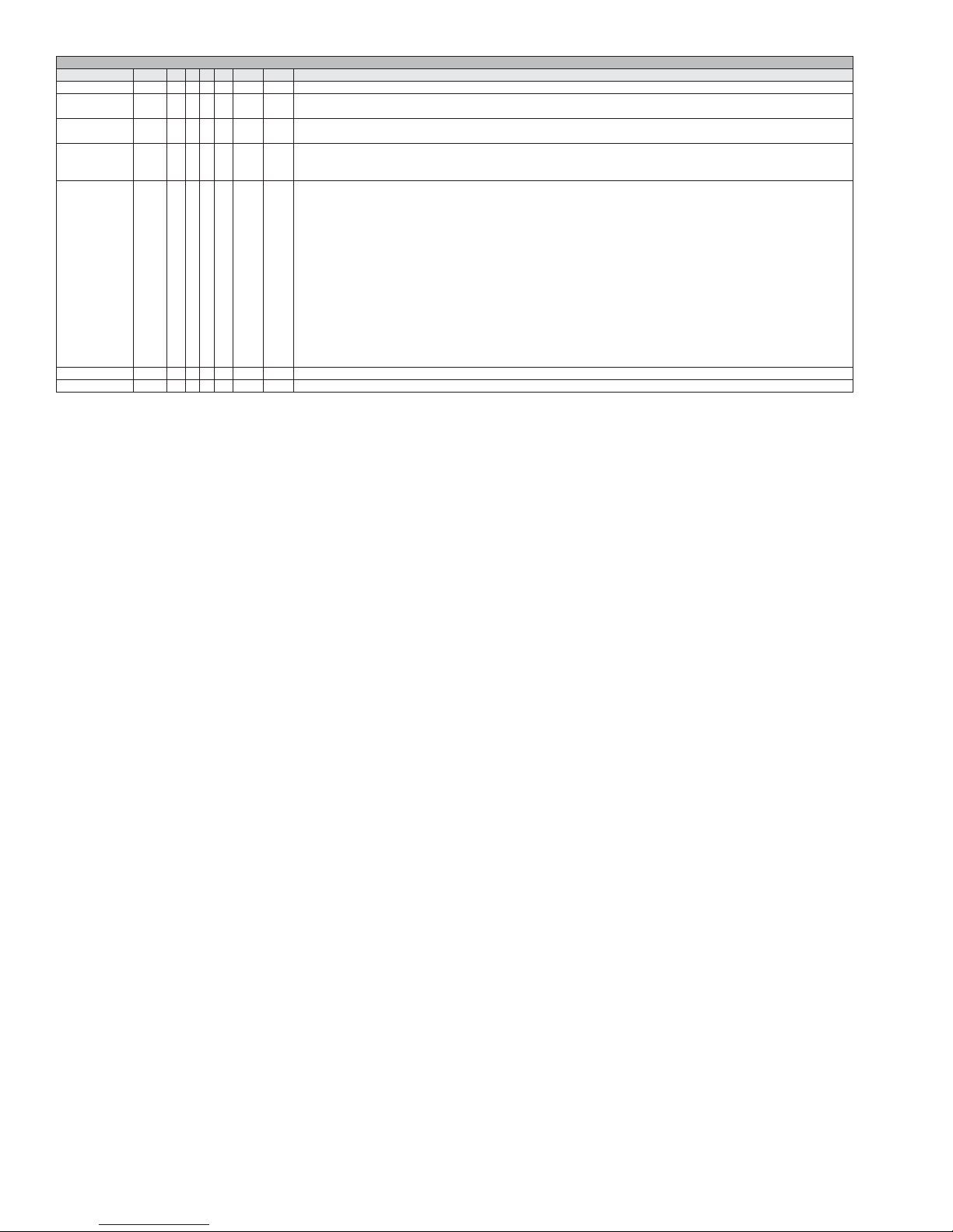
MODEL CHART
Example CRF2 -W R 0 1T -048 -M20 CRF2-WR01T-048-M20
Series CRF2 Capacitive level transmitter
Enclosure W
Probe
Type
Ground 0
Process
Connection
Probe Length XXX Insertion length in inches. Example 048 is 48˝ length. Rod type min: 24˝, max: 144˝; Cable type min: 24˝, max: 360˝
Options M20 M20 conduit connection with cable gland
R
R
C
A
U
1T
2T
3T
1B
2B
3B
1S
2S
3S
1F
2F
3F
4F
5F
6F
Weatherproof
Remote mount weatherproof housing
Rod
Cable
None included
Attached ground rod (3˝ or 4˝ ange process connection types only)
Unattached ground rod
3/4˝ NPT male
1˝ NPT male
1-1/2˝ NPT male
3/4˝ BSPT
1˝ BSPT
1-1/2˝ BSPT
1˝ sanitary clamp
1-1/2˝ sanitary clamp
2˝ sanitary clamp
2˝ 150# ange, 316 SS
2˝ 150# ange, PVC
3˝ 150# ange, 316 SS
3˝ 150# ange, PVC
4˝ 150# ange, 316 SS
4˝ 150# ange, PVC
OPERATING PRINCIPLE
Capacitance and Dielectrics
Capacitance is the property of two or more conductors to store a charge when there
is a voltage difference between the conductors. In other words capacitance relates
the voltage between two conductors and the amount of charge that can be held on
the conductors (i.e., the number of electrons). Capacitance is measured in Farads.
Since a Farad of capacitance represents a very large charge storage capacity,
most capacitance encountered is generally measured in microFarads (µF, 10-6) or
picoFarads (pF, 10-12). Capacitances encountered in level sensing applications are
generally in the 10’s or 100’s of pico Farads range.
The material between the conductors affects the capacitance also. Insulating materials
do not allow free movement of electrons, however in an electric eld the molecules
of these materials will tend to align with the eld thus storing energy. This is called
the dielectric effect and these materials are often referred to as dielectrics. When
placed between two conductors the energy storage capability of these dielectrics will
allow more charge to be stored on the conductors for a given voltage difference thus
increasing the capacitance between the conductors. The ratio of capacitance change
caused by these dielectrics is referred to as the dielectric constant. Different materials
have differing dielectric constants and will consequently change the capacitance
between two conductors more or less depending on the value of this constant. This
value ranges from 1.0 for a vacuum to over 100 for certain materials. The dielectric
constant for air is very close to 1.0 and usually assumed to be exactly 1.0.
Capacitive level sensors determine the level of material by changes in probe
capacitance resulting from the movement of dielectric materials between the probe
and the reference ground electrode such as a tank wall. Since measuring very small
capacitance changes (less than 1 pF) can be problematic in industrial environments,
capacitance level sensing tends to be most effective for materials with a dielectric
constant greater than 1.2. Since the difference in capacitance is being measured, it is
also possible to detect the level of two immiscible liquids that have different dielectric
constants such as oil and water.
Measurement
The CRF2 uses an impulse RF admittance measurement technique to measure
the probe capacitance. The impulse admittance measurement offers advantages
over other techniques in that it produces minimal emissions to interfere with other
communication or instrumentation systems. The CRF2 continuously measures the
probe capacitance. Using this capacitance measurement, it computes a linear value
with 0% at the zero calibration value and 100% at the span calibration value. From
this the output current is computed and generated. Since no assumptions are made
regarding the relative value of the zero and span calibration capacitances, the output
can be set to measure from low to high capacitance or high to low capacitance.
INSTALLATION
Unpacking
Remove the CRF2 from the shipping carton and inspect for damage. If damage is
found, notify the carrier immediately.
Materials
The CRF2 may be used to detect level of a variety of materials. Conductive materials
such as water require an insulated probe for proper operation. When used with a
conductive material, the material itself must be grounded to the reference ground of the
CRF2. This may be done through a conductive tank wall or using an optional reference
ground electrode. Dry non-conductive materials may use either an insulated or
uninsulated probe. Capacitance level measurement is best applied when the material
dielectric constant is greater than 1.2. With non-conductive materials, particularly low
dielectric materials, the probe should be spaced more closely to the reference ground
to increase the base capacitance and ensure reasonable sensitivity. The limiting factor
for spacing will be to ensure that material buildup around the probe is avoided. For
conductive materials this will be less of a concern since the dielectric insulator around
the probe is the predominant factor in the capacitance changes with level.
Page 3

Mounting Location
• The process temperature and ambient temperature must be within the specied
limits.
• The probe must be located away from tank inlets or chutes where material may fall
on the probe during lling or emptying.
• Avoid placing the probe close to agitators or other such devices.
• When used with high density bulk material, the probe must be protected from
material shifts that would bend or shift the probe.
• If a cable probe is used, make sure that shifting bulk material will not exert too much
strain on the cable connections.
The accuracy of the CRF2 is very dependent on the installation of the probe. The probe
must be installed vertically and parallel to the reference ground, particularly for nonconductive materials. The reference ground may be a conductive tank wall or other
internal parallel metallic structure. If these are unavailable then a reference electrode
must be installed with the probe (See Figure 1). Support for the probe and reference
electrode must be provided to ensure these components maintain their parallelism.
In nonmetallic tanks a ground reference must be provided. If the probe is near the
wall of the tank an adhesive backed metallic sheet may be applied to the outside tank
wall nearest to the probe. Other metallic objects may be used also if they are in close
proximity to the tank wall. If the probe is located further than 6 inches from the wall,
an internal conductor must be provided parallel to and within 6 inches of the probe.
Maintain a minimum of 1 inch spacing between the probe and the reference conductor.
These conductors must be connected to the case ground of the sensor. An internal
ground clamp is provided for this if other grounding is not available.
If turbulence or material movement within the tank could cause probe movement, the
probe must be supported appropriately with non-conductive material to minimize this
movement (See Figure 2).
When installing a unit that has a Remote Mount Housing, the probe should be
installed before the coaxial cable is connected. This will prevent twisting of the cable
and possible damage to the unit. The housing can be mounted in any position using
the bracket provided, being careful to prevent kinking or pulling the cable. The cable
should be connected to probe by inserting the cable through the cable gland on the
probe’s conduit enclosure and pushing the quick connect onto the spade terminal
provided. Be sure to replace the enclosure cover and tighten the cable gland to protect
and seal the connections.
Electrical Connection (See Figure 3)
CAUTION
Do not exceed the specied supply voltage rating. Permanent
damage not covered by the warranty may result. This unit is not
designed for AC voltage operation .
NOTE: Installation must be made in accordance with local codes and regulations.
When shing wire through the conduit connection do not allow the wire to touch or
press on components on the boards. Damage to the circuitry may result. Make sure
that the wire is routed so it will not interfere with the calibration switches.
The CRF2 provides a 1/2˝ NPT female port for conduit connection. The conduit
connection must be made such that condensation is not allowed to enter the sensor
housing. If necessary install a conduit breather drain in a separate conduit body to
prevent buildup of moisture. If nonmetallic conduit is used the protective ground may
be connected to the internal ground connection screw.
The CRF2 transmitter is designed as a two wire 4 to 20 mA device. Connection to
the board is through a two pin terminal block. The circuitry is non-polarized so the
positive and negative leads may be connected to either pin. It is recommended that
shielded twisted pair wire be used if the potential exists for interference from external
noise sources. Ground the shield at the case using the internal ground screw and
leave the other end of the shield open. Do not use the shield as one of the current
loop conductors.
The body of the CRF2 must be grounded to the tank or other earth ground using
the internal ground screw provided. If the tank is non-conductive then a reference
electrode must be provided. This reference electrode must be connected to the case
ground.
Power Supply
The transmitter requires a minimum of 10 Volts DC at its connection for proper operation,
and a maximum of 35 Volts. Choose a power supply with a voltage and current rating
sufcient to meet this power specication under all operational conditions. If the supply
is unregulated, make sure that the output voltage remains within the required voltage
range under all power line conditions. Ripple on the supply should not exceed 100 mV.
Loop Resistance
The maximum allowable loop resistance is dependent on the power supply voltage.
The maximum loop voltage drop must not reduce the transmitter voltage below the 10
Volt minimum. The maximum loop resistance can be calculated using the following
equation:
V
ps - 10.0
max =
R
Where V
20 mA
ps is the power supply voltage.
7-1/16
(179.39)
DEAD AREA
Figure 1: Attached Ground
“L”
SUPPORTS
6
(152.40)
MAX
Figure 2: Supports to
Rod Option
1
(25.40)
Tank Side Wall
Page 4

POWER
–+
SUPPLY
+
OUTPUT
Figure 3: Electrical Wiring Diagram
SETUP & CALIBRATION
Two multi-function buttons are provided for all calibration operations. With these you
can set the zero and span points, adjust the 4 and 20 mA calibration points, or reset
the 4 and 20 mA calibration points to the factory settings. All settings are stored in
nonvolatile memory so they will not be lost if the power is removed.
Zero and Span Calibration
The zero and span calibration is done with the CRF2 installed in the measured tank
or vessel. Calibrating zero or span can be done in either order as these settings are
independent of one another. The calibration can be done such that the output can go
from 4 to 20 mA or from 20 to 4 mA depending on the desired measurement for full
and empty conditions.
ZERO/
4-MA
RECEIVER/
READOUT
–
SPAN/
20-MA
Current Calibration
The 4 and 20 mA points of the CRF2 have been calibrated at the factory and generally
will not need to be recalibrated, but if needed the points may be recalibrated. To do this
you will need a milliammeter connected in the current loop.
To calibrate the 4 mA calibration point, ˝double click˝ the Zero/4 mA button by pressing
it twice within 1.5 seconds. The milliammeter will indicate approximately 4.00 mA.
Adjust the 4 mA set point by pressing the Zero/4 mA button to decrease the current and
the Span/20 mA button to increase the current. When complete, press both the Zero/4
mA and Span/20 mA buttons simultaneously to exit the calibration mode.
To calibrate the 20 mA calibration point, ˝double click˝ the Span/20 mA button by
pressing it twice within 1.5 seconds. The milliammeter will indicate approximately
20.00 mA. Adjust the 20 mA set point by pressing the Zero/4 mA button to decrease
the current and the Span/20 mA button to increase the current. When complete, press
both the Zero/4 mA and Span/20 mA buttons simultaneously to exit the calibration
mode.
NOTE: If the buttons are not pressed for approximately 4 minutes in calibrate mode,
the CRF2 will automatically revert to the normal operation mode.
Restore Factory Calibration
The factory 4 and 20 mA calibration points may be restored by pressing and holding
both the Zero/4 mA and Span/20 mA buttons simultaneously for 3 seconds. This must
be done in the normal operation mode.
MAINTENANCE & REPAIR
Other than the controls mentioned in this manual there are no user maintenance
adjustments or routine servicing required for this product. The unit is not eld
repairable and should be returned to the factory if service is required. Disassembly or
modications made by the user will void the warrantee and could impair the continued
safety of the product. If repair is required obtain a Returned Goods Authorization
(RGA) number and send the unit, freight prepaid, to the address below. Please include
a detailed description of the problem and conditions under which the problem was
encountered.
This symbol indicates waste electrical products should not be disposed
of with household waste. Please recycle where facilities exist. Check with
your Local Authority or retailer for recycling advice.
When the CLS2 with Sanitary Process Connection is to be used in a sanitary or hygenic
application, the unit must be cleaned and/or sanitized in accordance with appropriate
guidelines prior to installation. The CLS2 with Sanitary Process Connection is suitable
for “Clean In Place” methods.
The span or zero calibration is activated by pressing and holding the corresponding
˝Zero˝ or ˝Span˝ button for three seconds. Set the tank level to one endpoint (i.e., full
or empty), then press and hold either the Zero or Span button corresponding to the
desired endpoint. Set the tank to the other endpoint then press and hold the opposite
Span or Zero button. Calibration is now complete.
NOTE: Be careful to press the buttons only once within 3 seconds. Double clicking
the switches within 3 seconds will place the unit in current calibration mode. If this
happens press both buttons simultaneously to exit the current calibration mode. If
the calibration was accidentally changed, the factory calibration can be restored as
described later in ˝Restore Factory Calibration˝.
Printed in U.S.A. 1/19 FR# 443559-00 Rev. 7©Copyright 2019 Dwyer Instruments, Inc.
Dwyer Instruments Inc.
Attn: Repair Department
102 Highway 212
Michigan City, IN 46360
DWYER INSTRUMENTS, INC.
P.O. BOX 373 • MICHIGAN CITY, INDIANA 46360, U.S.A.
Phone: 219/879-8000
Fax: 219/872-9057
www.dwyer-inst.com
e-mail: info@dwyermail.com
 Loading...