

Merco Savory MHC-22-TDL, Tim Hortons MHC-22-TDL Parts And Service Manual
PARTS AND SERVICE MANUAL
FOR
MERCO HOLDING CABINET
MODEL MHC-22-TDL
HortonsServMan REV: K – 5/9/06
Garland Commercial Ranges
1177 Kamato Road
Mississauga, Ontario L4W 1X4
Canada
Facsimile: (905) 624-5669
Telephone: (905) 624-0260
SEQUENCE OF OPERATION
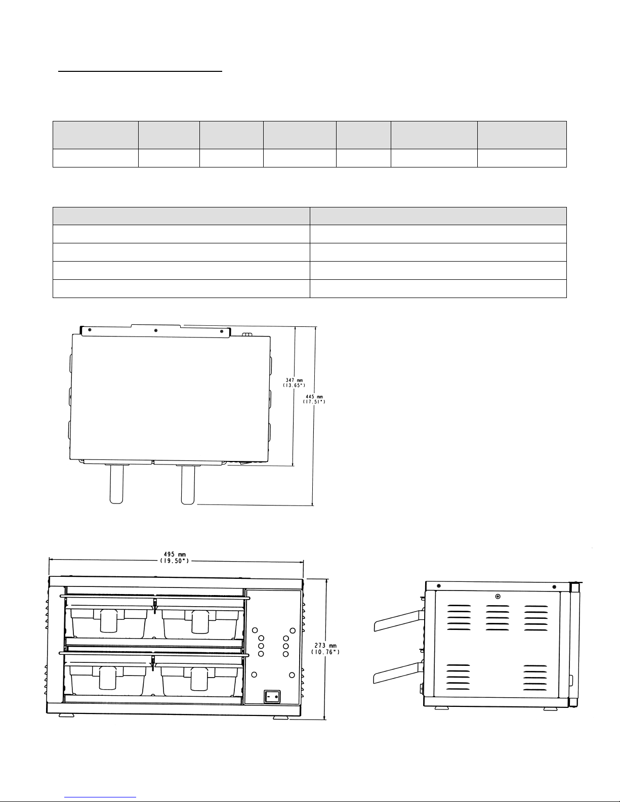
SPECIFICATIONS
Model # Voltage Amps Watts Hz.
Net Wt.
lbs./kg
Plug
MHC-22-TDL 120 10.4 1250 60 30/14 Nema 5-15P
TESTING VALUES
TEST VALUE
OHMS on elements 87 Ohms
AMP draw per element 1.3 Amps
OHMS on Temp Probes / Heater Plate 4.2 to 5.0 (depending on room temperature)
TRIAK testing / values 100 – 120 Volts
TOP VIEW
FRONT VIEW
SIDE VIEW
2
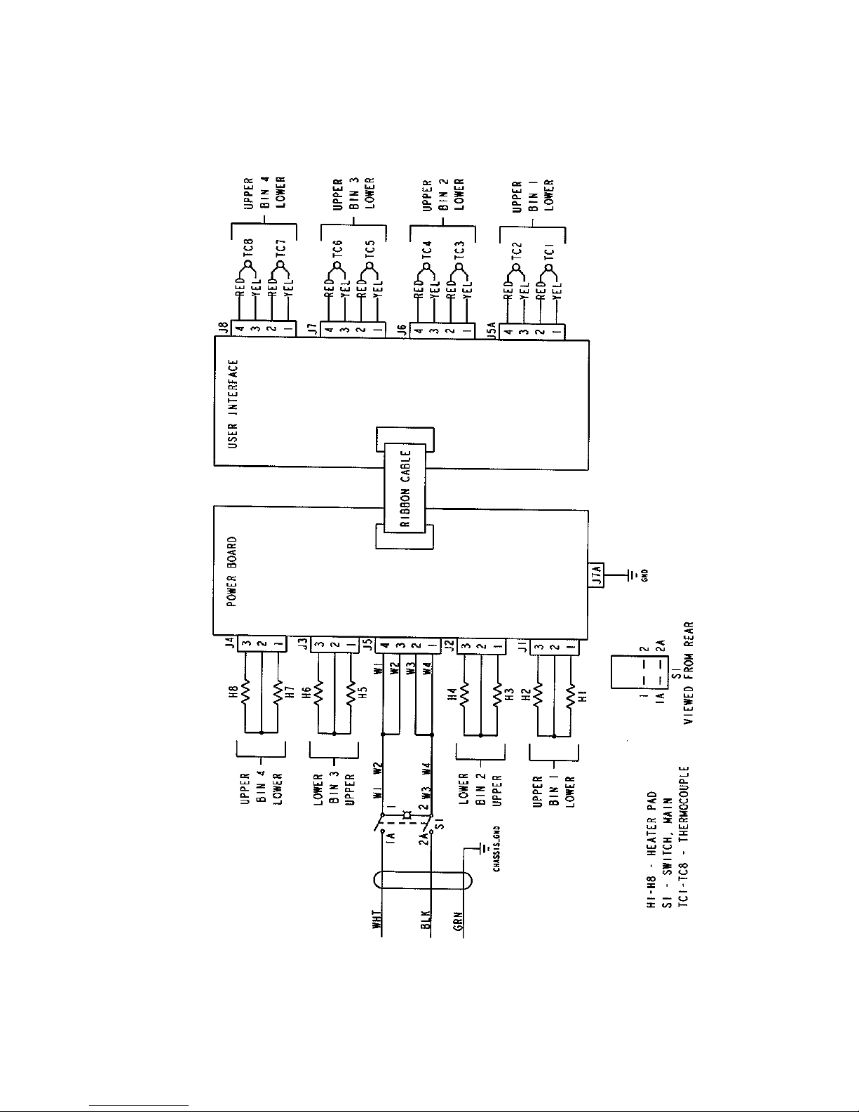
WIRING DIAGRAM
3
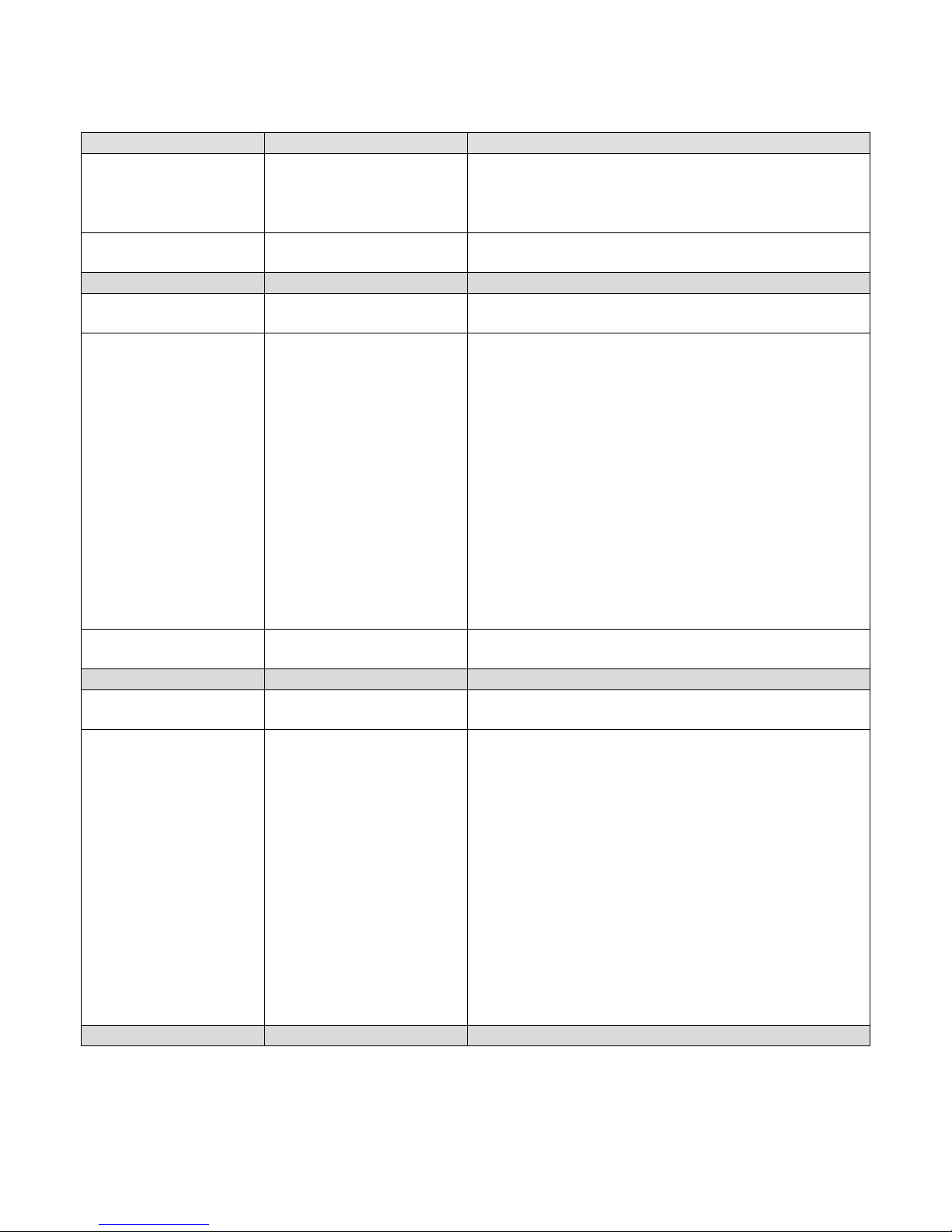
TROUBLESHOOTING GUIDE
SYMPTOM POSSIBLE CAUSE EVALUATION
Holding Cabinet will
not heat
Incoming Power Supply Verify power cord is secured firmly in receptacle.
Measure the incoming voltage. Check circuit
breakers. Reset if required. Call power company
if needed.
Power Switch Check continuity between switch terminals.
Replace switch as needed.
Unit doesn’t reach
desired temperature
Temperature is too
high
Thermocouple Check for continuity in circuit.
Heat Element Compare cavity temperature with display reading.
Insert temperature probe into center of cavity.
Acceptable temperature variation is +/- 20° from
display reading.
Check for loose connection.
Check the Amp draw on each element for proper
load. Check page 2 for rating information. If the
amp draw is high or low, check the individual
elements for opens, shorts and proper resistance.
WITH POWER OFF: To check resistance of the
elements, remove all leads from the elements and
use a digital multimeter.
The element resistance should be as follows:
120V – 87 ohms
Replace heating element (shelf) as needed.
Check thermostat (common wire). Please note
that if thermostat is bad, both circuits will be bad.
Thermocouple Check for incorrectly wired thermocouple.
Thermocouple wire polarities are reversed.
Heat Element Compare cavity temperature with display reading.
Insert temperature probe into center of cavity.
Acceptable temperature variation is +/- 20° from
display reading.
Check for loose connection.
Check the Amp draw on each element for proper
load. Check page 2 for rating information. If the
amp draw is high or low, check the individual
elements for opens, shorts and proper resistance.
WITH POWER OFF: To check resistance of the
elements, remove all leads from the elements and
use a digital multimeter.
The element resistance should be as follows:
120V – 87 ohms
Replace heating element (shelf) as needed.
4
 Loading...