

Merco FW, LFW, NW, HWFW, HWLFW Installation & Operating Instructions Manual
...
INSTALLATION & OPERATING
INSTRUCTIONS
for
MERCO® OVERHEAD FOOD WARMERS
MODELS FW & NW SERIES
EZNW-36 shown
Upon receipt of this unit, immediately unpack and inspect for possible concealed shipping damage. If unit is found
to be damaged, save all packing materials and contact your delivery carrier within 5 days. Refer to “Shipping
Damage Instructions” enclosed for detailed instructions. Failure to follow these instructions will negate Merco
Savory’s or your ability to file claims and receive compensation for shipping damage.
TO BE SERVICED ONLY BY AUTHORIZED PERSONS
P/N: 001201 REV: 8/8/07

GENERAL INFORMATION
MODELS FW, LFW, NW, HWFW, HWLFW, FW-DUAL and LFW-DUAL series with or without prefix EZ
Merco Food Warmers are shipped completely assembled with wiring and ready for mounting. Use wire suitable
for 90°C (200°F).
Each unit is shipped with two hanger tags mounted on each end. These should be used for chain mounting. Use
#16 single-jack chain or equivalent. For undershelf or pass-through installation on 8” wide models, bend the
hanger tag 90°.
INSTALLATION
CAUTION – on FW, EZFW, LFW, EZLFW, FW-DUAL, EZFW-DUAL, LFW-DUAL & EZLFW-DUAL series units,
do not install closer than ¼ inch from the top of the unit, 1 inch at ends, and 3 inches at the sides. Do not install
over a combustible surface closer than 12 inches for UL models and 15 inches for CSA models. On NW and
EZNW series warmers, do not install closer than 2 ¼ inches from the top of the unit, 1 inch at the ends, and 3
inches at the sides. Do not install over a combustible surface closer than 18 inches. On HWQFW, HWEZFW,
HWLFW, and HWEZLFW series warmers, do not install closer than 1 ½ inches from the top of the unit, 1 inch at
end, and 3 inches at the sides. Do not install over a combustible surface closer than 20 inches.
** Do not make any additional holes in the outside shell for BX or conduit. **
CAUTION
Remove packing from around center and both ends of the heat tube when installing this unit.
Use porcelain wire connectors – DO NOT USE PLASTIC WIRE CONNECTORS.
Use high-temp glass cloth electrical tape when securing connectors. DO NOT USE PLASTIC ELECTRICAL
TAPE.
If your unit was supplied with appliance lamps, they are teflon coated. When replacing these bulbs they must be
replaced with similarly coated bulbs. This is mandatory to comply with NSF regulations. These bulbs may be
purchased from one of the Merco Savory authorized maintenance and repair centers.
TEMPERATURE ADJUSTMENT
Standard Merco Food Warmers
The standard unit comes only with an on/off toggle switch and does not have the capability of adjustable heat.
Units with optional Infinite Control
Due to the wide variation in applications, products and environments, the control dial(s) have setting numbers for
your convenience. For this reason you will need to experiment with the control dial(s) to determine which setting
maintains the best food qualities for your products. Due to a break-in period, the settings may need adjusting
during the first 30 days. To adjust the control dial(s), turn the dial(s) to setting #4 and monitor the temperature of
your product. If the product temperature is too low, adjust the dial(s) to a higher setting. If the temperature is too
high, adjust the dial(s) to a lower setting.
CLEANING
Turn unit off or disconnect the power supply and allow a few minutes for the unit to cool down before cleaning.
Your unit should be wiped down daily with a soft damp cloth and cleaned weekly with a scotch-brite pad. Avoid
excessive water or cleaning solution on the unit as it may allow the electrical connections to become corroded
and/or cause the unit to fail. Your unit may require more frequent cleaning depending on conditions in your
particular environment. The heat tube should be rotated one or two turns weekly to ensure a clean and proper
connection which will help lengthen the life of the heating element(s).
2
FW & NW Series Ops Manual
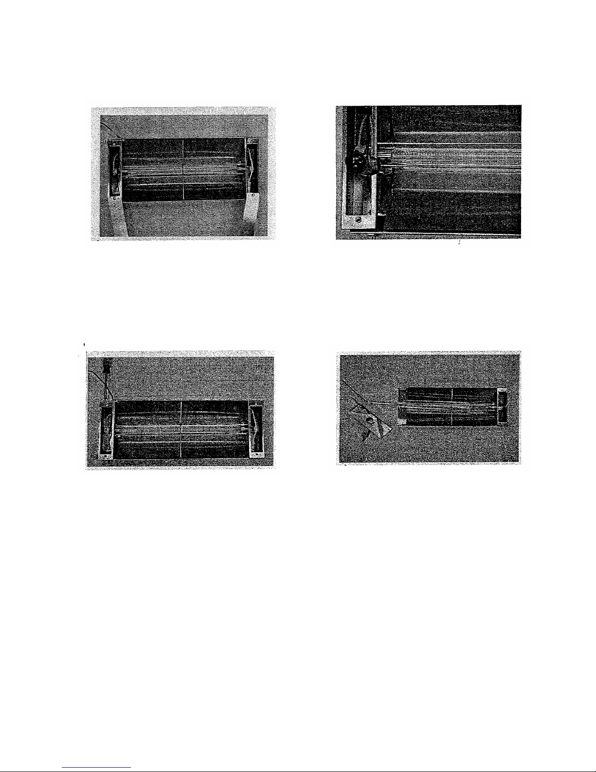
1. Remove the 4 screws holding
the access panels onto the unit
(2 per panel).
3. Remove the hex headretaining nut from the on/off
switch. Remove the 3 screws
holding the end panel onto the
unit (switch end).
2. Loosen the screws on the
heat tube collars (one on each
end of the tube).
4. Carefully remove the end
panel, remove the on/off switch
and disconnect the white wire.*
Remove the wire nut from the
opposite end of the heat tube.
The tube is now ready to be
taken out of the unit.
5. Reassemble in reverse order.
* For units with an infinite control, both ends of the heat tube will have wire nuts.
FW & NW Series Ops Manual
3
 Loading...