

Mercia Garden Products 06LOG127SG-V1, 06LOG127DG-V1 Instruction manual
General Instructions
Please retain product label and instructions for future reference
06LOG127SG-V1 & 06LOG127DG-V1
06LOG127SG-V1 28mm 3x3m corner cabin with single (glass) glazing.
06LOG127DG-V1 28mm 3x3m corner cabin with double (glass) glazing.
BEFORE YOU START PLEASE READ INSTRUCTIONS CAREFULLY
- Check the pack and make sure you have all the parts listed.
- When you are ready to start, make sure you have the right tools at hand (not supplied)
including a Phillips screwdriver, Stanley knife, wood saw, step ladder and drill with 2mm
bit.
- Ensure there is plenty of space and a clean dry area for assembly.
TIMBER
As with all natural materials, timber can be aected during various weather conditions.
For the duration of heavy or extended periods of rain, swelling of the wood panels may
occur. Warping of the wood may also occur during excessive dry spells due to an interior
moisture loss. Unfortunately, these processes cannot be avoided but can be helped. It is
suggested that the outdoor building is sprayed with water during extended periods of
warm sunshine and sheltered as much as possible during rain or snow.
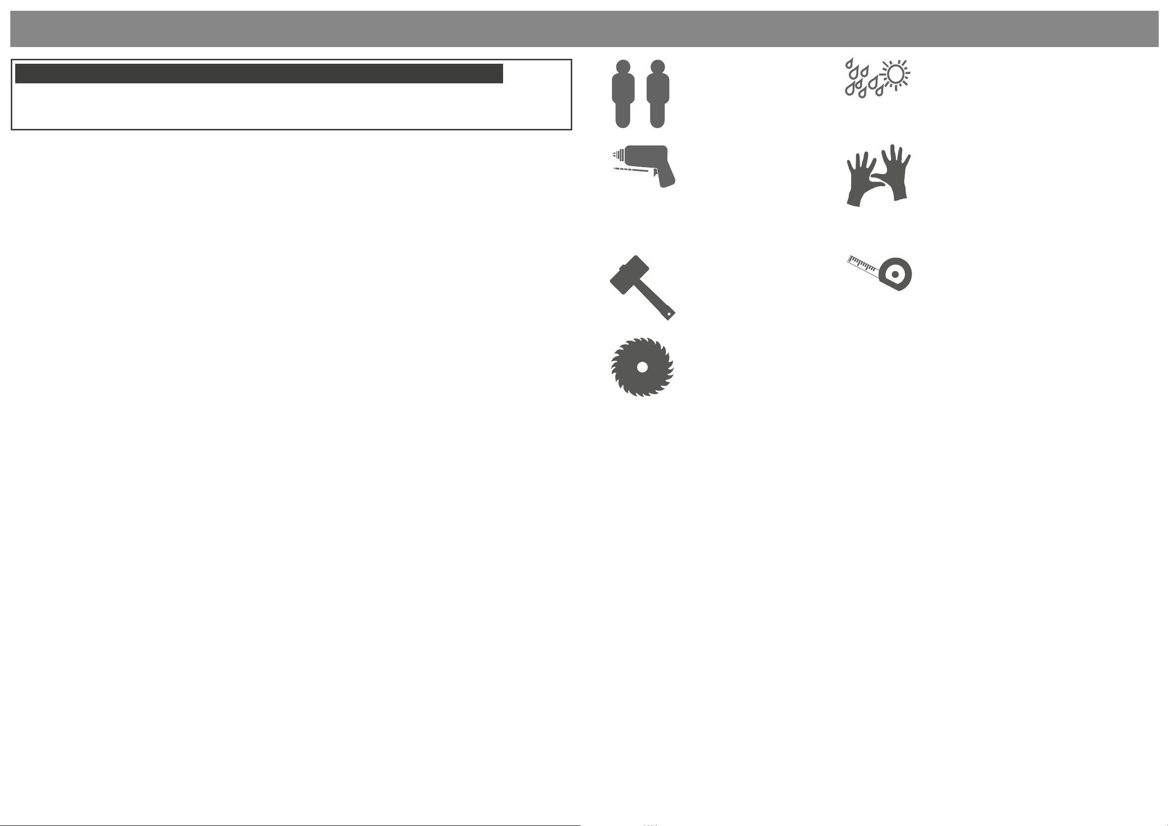
2mm Drill bit
All building’s should be
erected by two adults
For ease of assembly, you
MUST pilot drill all screw
holes and ensure all screw
heads are countersunk.
For ease of assembly use a
rubber mallet to t the log
boards. Do NOT use a heavy
hammer.
It is advisable to use a
circular saw when cutting
roof and oor boards.
Winter = High Moisture = Expansion
Summer = Low Moisture = Contraction
CAUTION
Every eort has been made during the
manufacturing process to eliminate the
prospect of splinters on rough surfaces of the
timber. You are strongly advised to wear gloves
when working with or handling rough sawn
timber.
Ensure to measure and check before cutting
boards.
Our buildings are pre treated with a water based treatment**; this only helps to protect
the product during transit and for upto 3 months against mould. To validate your
guarantee and ensure longevity of the product, it is ESSENTIAL the building is treated
with a wood preserver within the rst three months of assembly and thereafter in
accordance with the manufactures recommendations. Care must be taken to ensure
the product is placed on a suitable base.
BUILDING A BASE
When thinking about where the building and base is going to be constructed:
Ensure that there will be access to all sides for maintenance work and annual
treatment.
Ensure the base is level and is built on rm ground, to prevent distortion. Refer to
diagrams for the base dimensions, The base should be slightly smaller than the external
measurement of the building, i.e. The cladding should overlap the base, creating a run
o for water. It is also recommended that the oor be at least 25mm above the
surrounding ground level to avoid ooding.
TYPES OF BASE
- Concrete 75mm laid on top of 75mm hard-core.
- Slabs laid on 50mm of sharp sand.
Whilst all products manufactured are made to the highest standards of Safety and in
the case of childrens products independently tested to EN71 level, we cannot accept
responsibility for your safety whilst erecting or using this product.
For assistance please contact customer care on: 01636 880514
Mercia Garden Products Limited,
Sutton On Trent,
Newark,
Nottinghamshire,
NG23 6QN
Refer to the instructions pages for you specic product code
www.merciagardenproducts.co.uk
P 1
06LOG127SG-V1 & 06LOG127DG-V1
Please retain product label and instructions for future reference
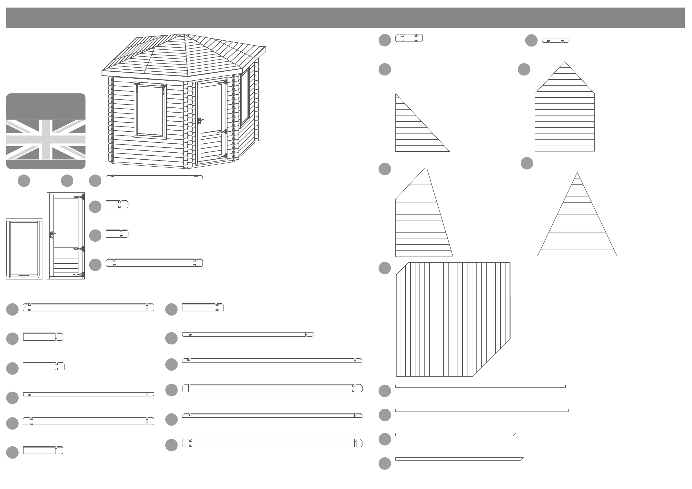
Overall Dimensions:
Width = 4482mm
Depth = 3723mm
Height = 2923mm
Base Dimensions:
Width = 3255mm
Depth = 3899mm
Before assembly
please make sure you have a
suitable base ready to erect your
building
MADE IN GREAT BRITAIN
21
3
Starter Board (S1) - 28x66x1515mm
LB28RT66-1515mm
4
Log Board (B) - 28x120x347mm Left QTY 18
LB28-347mm (Left)
5
Log Board (B) - 28x120x347mm Right QTY 18
LB28-347mm (Right)
19
Log Board (A) - 28x120x652mm QTY 20
LB28-652mm
21
Roof Board Pack 1
AI-01LOG127SG/DG-V1RBP1
MB16P-1010mm (Angled) QTY 6
MB16P-906mm (Angled) QTY 6
MB16P-801mm (Angled) QTY 6
MB16P-697mm (Angled) QTY 6
MB16P-592mm (Angled) QTY 6
MB16P-488mm (Angled) QTY 6
MB16P-383mm (Angled) QTY 6
MB16P-279mm (Angled) QTY 6
MB16P-174mm (Angled) QTY 6
MB16P-70mm (Angled) QTY 6
Roof Board Pack 3
AI-01LOG127SG/DG-V1RBP3
23
MB16P-1077mm (Angled) QTY 2
MB16P-1044mm (Angled) QTY 2
MB16P-1011mm (Angled) QTY 2
MB16P-978mm (Angled) QTY 2
MB16P-945mm (Angled) QTY 2
MB16P-912mm (Angled) QTY 2
MB16P-878mm (Angled) QTY 2
MB16P-845mm (Angled) QTY 2
MB16P-812mm (Angled) QTY 2
MB16P-779mm (Angled) QTY 2
MB16P-704mm (Angled) QTY 2
MB16P-566mm (Angled) QTY 2
MB16P-428mm (Angled) QTY 2
MB16P-291mm (Angled) QTY 2
MB16RG92P-153mm (Angled) QTY 2
22
24
20
Log Board (AR) - 28x54x652mm
LB28RG54-652mm
Roof Board Pack 2
AI-01LOG127SG/DG-V1RBP2
MB16-1114mm QTY 18
MB16P-1114mm (Angled) QTY 2
MB16P-1040mm (Angled) QTY 2
MB16P-831mm (Angled) QTY 2
MB16P-623mm (Angled) QTY 2
MB16P-414mm (Angled) QTY 2
MB16P-206mm (Angled) QTY 2
Roof Board Pack 4
AI-01LOG127SG/DG-V1RBP4
MB16P-1407mm (Angled) QTY 1
MB16P-1381mm (Angled) QTY 1
MB16P-1274mm (Angled) QTY 1
MB16P-1168mm (Angled) QTY 1
MB16P-1062mm (Angled) QTY 1
MB16P-955mm (Angled) QTY 1
MB16P-849mm (Angled) QTY 1
MB16P-742mm (Angled) QTY 1
MB16P-636mm (Angled) QTY 1
MB16P-530mm (Angled) QTY 1
MB16P-423mm (Angled) QTY 1
MB16P-317mm (Angled) QTY 1
MB16P-211mm (Angled) QTY 1
MB16P-104mm (Angled) QTY 1
6
Log Board (A) - 28x120x1515mm QTY 2
Window
Door
LB28-1515mm
QTY 2
7
Log Board (A) - 28x120x2054mm Left QTY 8
LB28-2054mm
8
Log Board (B) - 28x120x652mm QTY 12
LB28-652mm
9
Log Board (B) - 28x120x652mm Left QTY 12
LB28-652mm Left
10
Log Board (AR) - 28x66x2054mm Left
LB28RT66-2054mm Left
11
Log Board (A) - 28x120x2054mm Right QTY 8
LB28-2054mm Right
12
Log Board (B) - 28x120x652mm QTY 12
LB28-652mm
13
Log Board (B) - 28x120x652mm Right QTY 12
LB28-652mm Right
14
Log Board (AR) - 28x66x2054mm Right
LB28RT66-2054mm Right
15
Log Board (S1) - 28x66x2662mm Left
LB28RT66-2662mm Left
16
Log Board (A) - 28x120x2662mm Left QTY 20
LB28-2662mm Left
17
Log Board (S1) - 28x66x2662mm Right
LB28RT66-2662mm Right
18
Log Board (A) - 28x120x2662mm Right QTY 20
LB28-2662mm Right
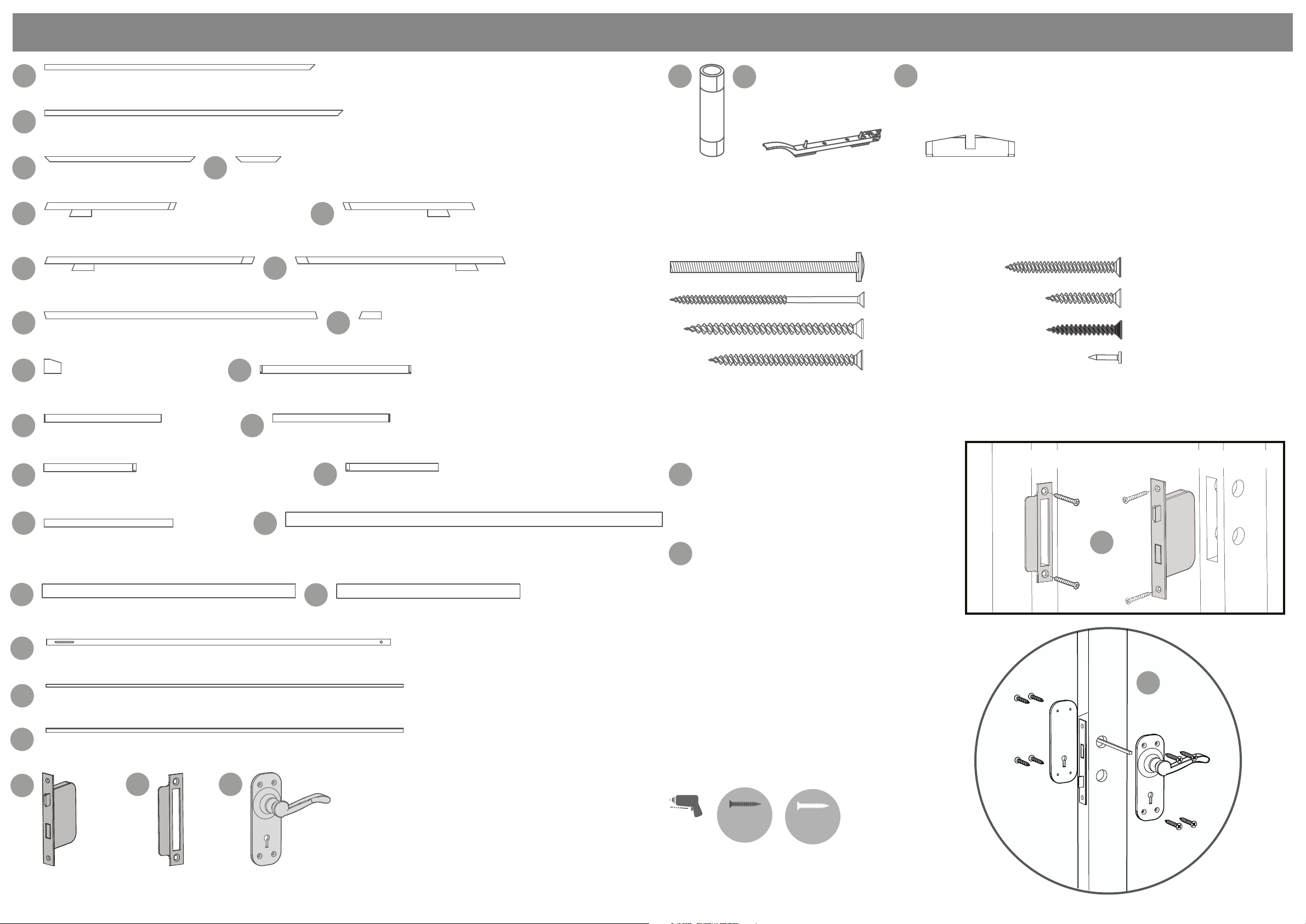
25
26
Bearer - 44x44x2669mm QTY 9
F4444-2669mm
27
Bearer - 44x44x2713mm
F4444-2713mm
28
Bearer - 44x44x1890mm QTY 2
F4444-1910mm (Angled)
29
Bearer - 44x44x2005mm
F4444-2025mm (Angled)
Floor Board Pack
AI-01LOG127SG/DG-V1FBP
MB16P-2531mm (Angled tongue side) QTY 1
MB16P-2643mm (Angled tongue side) QTY 1
MB16P-2696mm (Angled tongue side) QTY 1
MB16-2696mm QTY 13
MB16P-2696mm (Angled groove side) QTY 1
MB16P-2597mm (Angled groove side) QTY 1
MB16P-2485mm (Angled groove side) QTY 1
MB16P-2373mm (Angled groove side) QTY 1
MB16P-2261mm (Angled groove side) QTY 1
MB16P-2149mm (Angled groove side) QTY 1
MB16P-2037mm (Angled groove side) QTY 1
MB16P-1925mm (Angled groove side) QTY 1
P 2
Please retain product label and instructions for future reference
30
Bearer - 44x44x2248mm
F4444-2268mm (Angled)
31
Bearer - 44x44x2481mm
F4444-2501mm (Angled)
32
Bearer - 44x44x1253mm
F4444-1293mm (Angled)
34
33
Bearer - 44x44x394mm
F4444-434mm (Angled)
35
Centre Purlin Right - 1095mm QTY 3
AI-06LOG127SG/DG-V1CPR
36
Front Purlin Left - 1746mm
AI-06LOG127SG/DG-V1FPL
37
Front Purlin Right - 1746mm
AI-06LOG127SG/DG-V1FPR
38 39
Long Purlin - 45x70x2273mm QTY 3
F4570-2313mm (Angled)
40 41
Spider Block - 45x120x143mm
F45120-163mm (Angled)
Top Block Door - 28x80x1254mm
LB28RG80-1254mm (Angled)
Centre Purlin Left - 1095mm QTY 3
AI-06LOG127SG/DG-V1CPL
Roof Block - 45x70x185mm QTY 3
F4570-205mm (Angled)
56
Felt
Nail Bag
57
Casement Stay QTY 2
58
Corner Top Block
AI-06LOG127-V1BACKB
80mm Bolt Set x17
120mm Screw x20
90mm Screw x100
70mm Screw x172
40mm Screw x353
30mm Screw x76
30mm Black Screw x21
Felt Tacks x867
42 43
Top Block Left - 28x80x974mm
LB28RG80-974mm (Angled)
44
Top Block Back Right - 28x80x768mm QTY 3
LB28RG80-768mm (Angled)
46
Top Block Centre 28x80x1071mm QTY 2
LB28RG80-1071mm
48
Window Fascia - 16x120x2160mm QTY 2
S16120-2160mm
50
Storm Brace - 27x44x2100mm QTY 8
F2744-2100mm
51
Skirting - 28x28x2400mm QTY 8
FS2828-2400mm
52
Interior Roof Trim - 27x44x2400mm QTY 8
F2744-2400mm
53
54
55
Top Block Right - 28x80x974mm
LB28RG80-974mm (Angled)
45
Top Block Back Left - 28x80x768mm QTY 3
LB28RG80-768mm (Angled)
47
Rear Fascia - 16x120x3145mm QTY 2
S16120-3145mm
49
Front Fascia - 16x120x1700mm
S16120-1700mm
Step 1
Fit the mortice lock (No. 53) into the recess
a
in the door (No. 2) and secure using the
screws provided. Attach the key plate
(No. 54) to the door framing with the
screws provided.
b
Fit the door handles (No.55) and connect
with the metalbar to the mortice lock
using 8x30mm screws. Ensure the lock
mechanism closes correctly. If not, remove
the lock and turn the catch around using
the small grub screw.
*Please note: This image is for illustrative purposes
and may dier from your choice in product
(regarding ironmongery). Nevertheless the process
of xing is the same.
8x30mm Black Screws
12x30mm Screws
The Mortice Lock is Reversible
a
b
Mortice Lock
Key Plate
Handles (Pair)
Pre drill
hole
30mm
screw
30mm
screw
P 3
Please retain product label and instructions for future reference
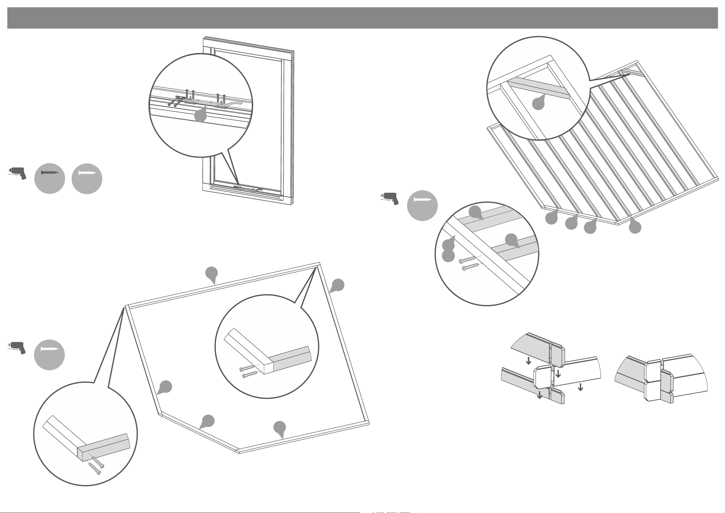
Step 2
Fix the casement stay (No. 57) onto
the window (No. 1) and the casement
stay pins to the window cill using
6x30mm (black) screws per casement
stay.
*Ensure the casement stay is centralised
on the window.
12x30mm Black Screws
12x30mm Screws
Depending on Ironmongery choices
Pre drill
hole
30mm
screw
30mm
screw
Step 3
57
Step 4
Following the same method
outlined in Step 3, arrange the
remaining framing (No’s. 26, 29
30, 31 & 33) as shown in the
illustration.
*Ensure there is an equal
amount of space between each
frame.
Secure each of the frames in place
using 4x70mm screws per frame,
ensuring the framing remains level.
44x70mm Screws
Pre drill
hole
70mm
screw
26
33
29
30
31
26
Lay the starters (No’s. 26, 27, 28
& 32) onto a rm and level surface
(free from areas where standing
water can collect) as shown in the
illustration.
Fix the framing together at each
corner using 10x70mm screws,
ensuring the frame is ush.
10x70mm Screws
Pre drill
hole
70mm
screw
27
26
28
27
26
Pre-assembly
*Please note:
Each board interlocks at
either end in a staggered pattern.
28
Before securing ensure that the boards
are tted properly in their respective
tongue’s and groove’s.
32
28
P 4
 Loading...