

Mercia Garden Products 03OVLPBRN0705-V2 Instruction manual

03OVLPBRN0705-V2
16/03/2012
Please retain product label and instructions for future reference
Overall Dimensions:
Length = 1490mm
Width = 2131mm
Height = 2195mm
Base Dimensions:
Length = 1448mm
Width = 2082mm
Before assembly
please make sure you have a
suitable base ready to erect your
building
1
Door Gable
Qty 1
4
2
3
Plain Gable
Qty 1
5
6
Plain Side
Qty 2
7
MADE IN GREAT BRITAIN
BEFORE YOU START PLEASE READ INSTRUCTIONS CAREFULLY
x2
- Check the pack and make sure you have all the parts listed.
- When you are ready to start, make sure you have the right tools at hand
(not supplied) including a Phillips screwdriver, Stanley knife, wood saw,
step ladder and drill with 2mm bit.
- Ensure there is plenty of space and a clean dry area for assembly.
TIMBER
As with all natural materials, timber can be aected during various weather
conditions. For the duration of heavy or extended periods of rain, swelling of the
wood panels may occur. Warping of the wood may also occur during excessive
dry spells due to an interior moisture loss. Unfortunately, these processes cannot
be avoided but can be helped. It is suggested that the outdoor building is
sprayed with water during extended periods of warm sunshine and sheltered as
much as possible during rain or snow.
Our buildings are delivered pre-treated with a water based timber treatment
however this only helps to protect during transit of your garden item. To
validate your guarantee and for better protection against weathering it is
ESSENTIAL that you treat the garden building with a wood preserver within 3
months of assembly. This will need to be re-applied annually to ensure longevity
of your building. Care must be taken when constructing the garden building
that it is not touching the ground and is on a suitable base.
BUILDING A BASE
When thinking about where the building and base is going to be constructed: Ensure that there will be access to all sides for maintenance
work and annual treatment.
TYPES OF BASE
- Concrete 75mm laid on top of 75mm hard-core.
- Slabs laid on 50mm of sharp sand.
Ensure the base is level and is built on rm ground, to prevent distortion. Refer to diagrams for the base dimensions, The base should be
slightly smaller than the external measurement of the building, i.e. The cladding should overlap the base, creating a run o for water. It is also
recommended that the oor be at least 25mm above the surrounding ground level to avoid ooding.
Whilst all products manufactured are made to the highest standards of Safety and in the case of childrens products independently tested to EN71
level, we cannot accept responsibility for your safety whilst erecting or using this product.
Mercia Graden Products Limited, Sutton On Trent, Newark, Nottinghamshire, NG23 6QN
www.merciagardenproducts.co.uk
2mm Drill bit
For Assistance Please
Contact Customer Care on
01636 880514
This building should be erected by
two adults
For ease of assembly, you must pilot
drill all screw holes and ensure all
screw heads are countersunk.
Winter = High Moisture = Expansion
Summer = Low Moisture = Contraction
Floor
Qty 1
Fixing Kit
8
9
10
11
12
13
Roof Eave - 27x32x1720mm Qty 2
Ridge Bar - 27x44x1457mm Qty 1
Fascia - 12x80x1240mm Qty 4
Centre Fascia Block- 44x44x340mm Qty 1
Fascia Block- 27x44x140mm Qty 2
Finial - Qty 2
Slave Door
Qty 1
Master Door
Qty 1
15
17
19
14
Press lock
Qty 1
Chrome
Handle
Qty 2
Roof Sheet
Felt
Qty 2
16
18
20
Butt Hinge
Qty 6
Barrel Bolt
Qty 2
Corner
Brace
Qty 2
Turn
button
Nail Bag
30mm Screw x 34
25mm Black Screw x 7
25mm Screw x 36
10mm Screw x 14
Felt Tacks x 75
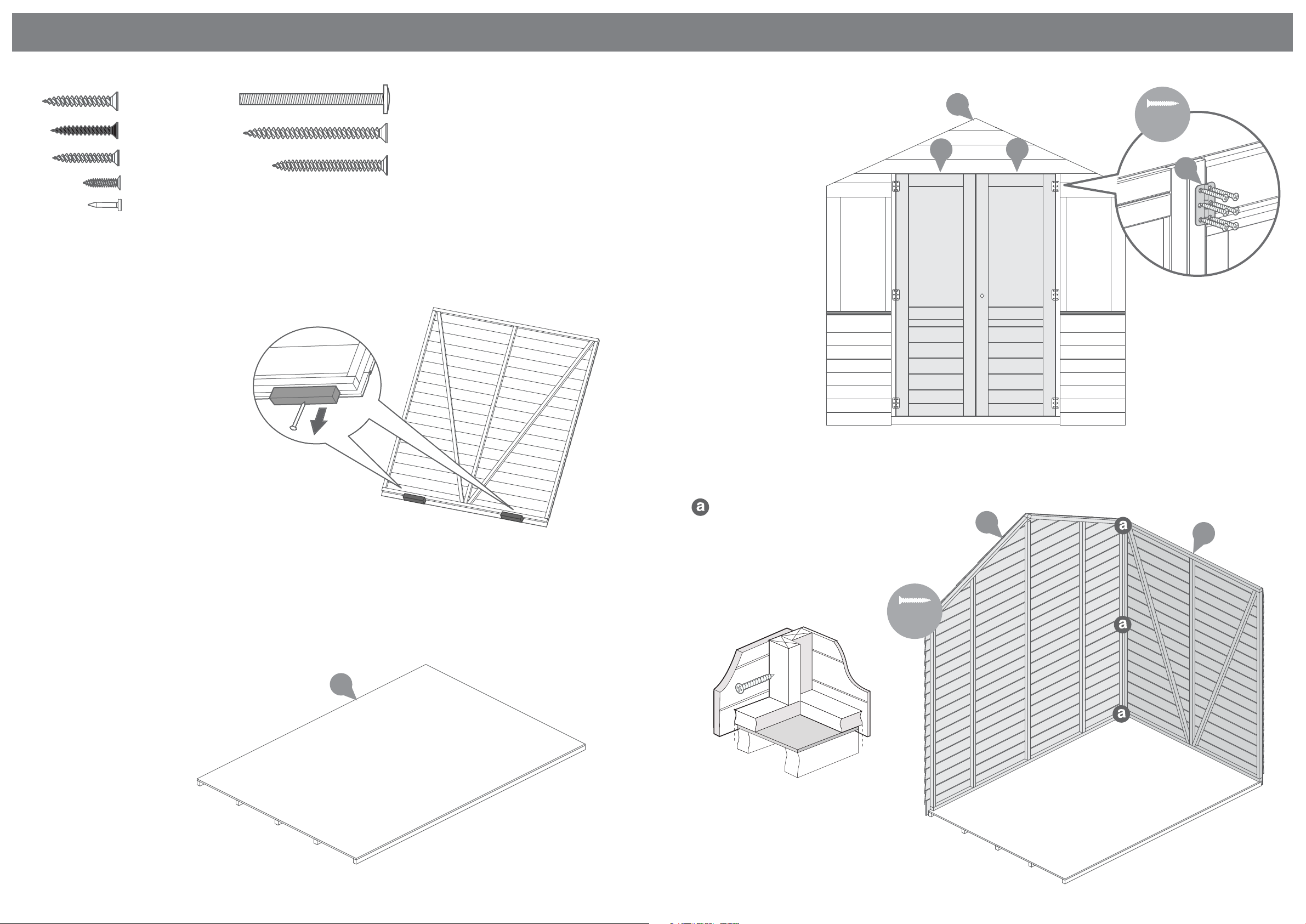
Step 1
Remove transportation blocks
from the bottom of each panel
before beginning assembly.
Each panel should have two
blocks.
35mm Bolt x x4
50mm Screw x 32
40mm Screw x 22
Step 3
Fix the Butt Hinges to the Door Gable
using 30mm screws ensuring that the
screws go through to the framing.
1
30mm
screw
5
6
14
Step 2
Place the floor on a firm and
level base, ensure the base has
suitable drainage free from areas
where standing water can
collect. (See front page on base
requirements).
36x 25mm Screws
Step 4
Fix the corners with 50mm
screws as shown in diagram.
Position the panels so there is equal spacing
between the floor and cladding on all 4 sides
50mm
screw
4
2
3
3 x 50mm Screws
 Loading...