

User Guide
XENTRY Kit 2
XENTRY Kit MT 2
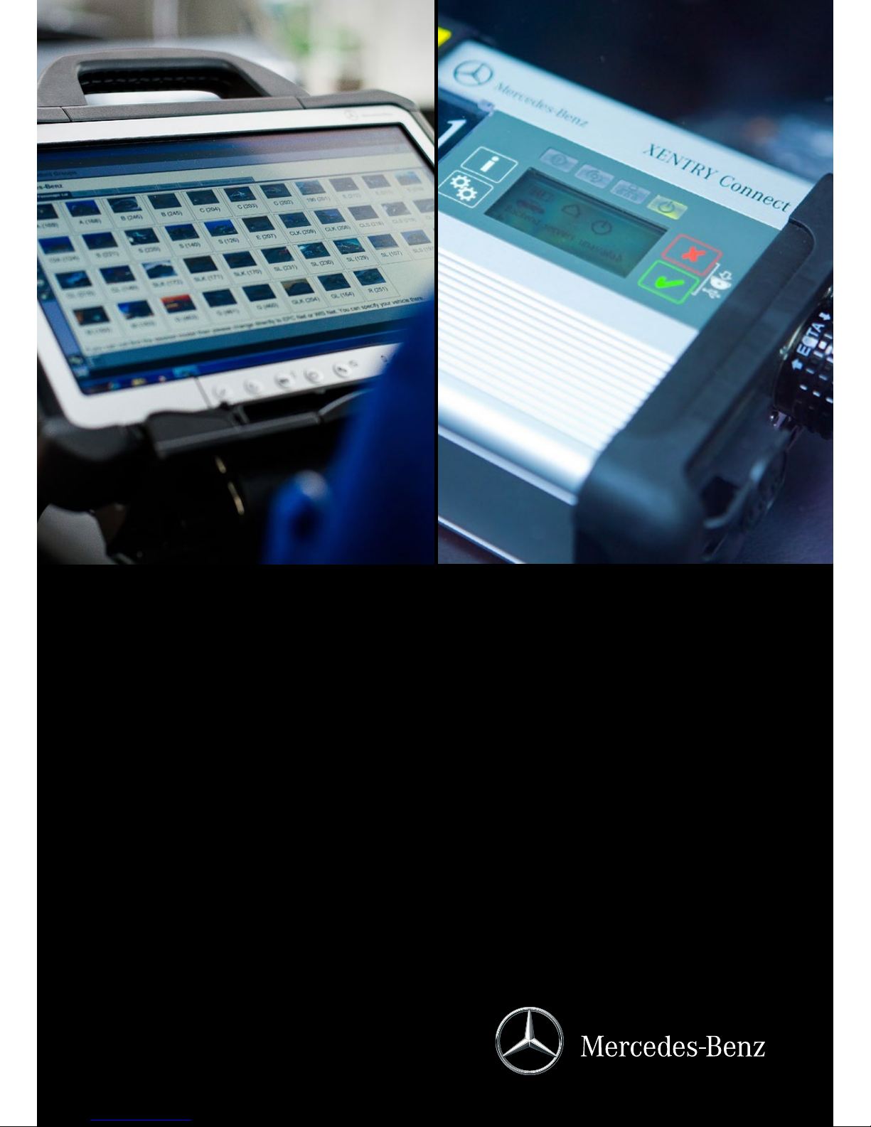
XENTRY Connect

2
Important: Read carefully before using! Retain for future reference
Version 1.3 last updated 09/2014
Copyright 2014 Daimler AG. All rights reserved. All texts, pictures, graphics, audio, video and animation les, as well as their arrangements, are subject to copyright protection
and other statutes for protecting intellectual property. They may neither be copied for commercial purposes nor for dissemination, nor may they be modied or used on other
websites. Some of the Daimler AG webpages also include material which is subject to the copyright protection of those parties who have made it available.

6 XENTRY Connect 21
6.1 Technical Performance Features 21
6.2 Interfaces on the XENTRY Connect 21
6.2.1 Socket for the XENTRY Connect power supply unit 21
6.2.2 USB Connections 21
6.2.3 Connecting XENTRY Connect to the vehicle (cable) 22
6.3 XENTRY Connect operating panel 22
6.3.1 Button Lock on the XENTRY Connect 22
6.3.2 LEDs and Search Tone 22
6.3.3 Display 23
6.3.4 Upper section of the XENTRY Connect display 23
6.3.5 Lower section of the XENTRY Connect display 24
6.3.6 Background Illumination Statuses 24
6.3.7 Buttons of the XENTRY Connect 24
6.4 Starting and Shutting Down the XENTRY Connect 25
6.5 Battery Compartment 25
7 XENTRY Tab 2 26
7.1 Technical Performance Features 26
7.2 Interfaces on the XENTRY Tab 2 26
7.3 XENTRY Tab 2 function buttons 27
7.4 Panasonic Dashboard 27
7.5 Virtual Keyboard 27
7.6 Own Software on the XENTRY Tab 2 27
7.7 XENTRY Tab 2 docking station 28
7.8 Printers and Printing 28
7.9 XENTRY Printer Bridge 28
7.10 Windows Settings 28
Table of Contents
1 Safety information and
product liability 5
2 New Features with XENTRY Kit 2 7
3 Scope of supply 8
3.1 XENTRY Kit 2 scope of supply 8
3.2 XENTRY Connect scope of supply 8
3.3 XENTRY Tab 2 scope of supply 9
4 System Requirements and Network Integration 10
4.1 Network Proles: Connecting the XENTRY Connect
to the XENTRY Tab 2 11
4.1.1 Workshop Mode 11
4.1.2 Service24h mode 11
4.1.3 Cabled online mode 12
4.1.4 Mixed Operation 12
4.2 Minimum technical requirements and restrictions on
use of a standard PC 12
5 InitialStartupandConguration 13
5.1 Brief overview of initial XENTRY system startup 13
5.2 Conguration of the overall system 14
5.2.1 Conguration (dialog-guided, CongAssist) 14
5.2.2 Expert mode initial startup 16
5.3 Checking the Back-end Connections 18
5.4 Order StartKey 19

8 Connection of Accessories 29
8.1 XENTRY Measurement Technology HMS 990 USB 29
8.2 SBC Flash Box 29
8.3 MoTelDis 30
8.4 Chip Card Reader 30
8.5 Injector scanners (2D hand-held scanners) 30
8.6 Diagnostic unit for HV batteries 30
9 XENTRY Control 31
9.1 Starting XENTRY Control 31
9.2 XENTRY Control selection screen 31
9.2.1 XENTRY Connect statuses 32
9.2.2 Menu and displays in the XENTRY Control
selection screen 32
9.3 Working with XENTRY Control and
XENTRY Connect 33
9.3.1 Deskband 34
9.3.2 Deskband pop-up 34
10 Operating tools 36
10.1 Support Tool 36
10.2 StartKey Center 37
10.3 UpdateAssist 38
10.4 AddOn Center 38
11 Update & Recovery 40
11.1 XENTRY Connect update 40
11.1.1 XENTRY Kit 2 Software Blu-ray Disc 40
11.1.2 XENTRY Connect online update (add-ons) 41
11.2 XENTRY Connect recovery 41
11.3 XENTRY Tab 2 update 41
11.3.1 XENTRY Kit 2 Software Blu-ray Disc (BD) 41
11.3.2 XENTRY Tab 2 online update (add-ons) 42
11.3.3 Windows Updates on the XENTRY Tab 2 42
11.3.4 Virus Scanner Update 42
11.4 XENTRY Tab 2 Recovery 42
11.5 Recovery of the XENTRY Tab 2 42
11.5.1 Windows 7 (32-bit) Installation 42
11.5.2 Installation of the XENTRY Kit 2 Software
Blu-ray Disc (BD) 46
12 XENTRY HMS 990 USB
Measurement Technology 49
12.1 Components 50
12.2 Connecting the hardware 51
12.3 Software 52
12.4 Starting and shutting down 52
12.5 Automatic software download when starting the
XENTRY HMS 990 USB Measurement Technology 52
12.6 Display and status area in the main menu 54
12.7 Menu items and submenus 54
13 Automatic Quick Test (AKT) 58
13.1 Prerequisites for AKT 58
13.2 Activation / deactivation of AKT 58
13.2.1 AKT activation 58
13.2.2 AKT generation 59
13.2.3 AKT deactivation 60
13.3 Notes on XENTRY Portal and AKT 60
13.4 AKT-supported model series 60
14 Service & Support 61
14.1 Diagnosis User Help Desk (UHD) 61
14.2 Accessory Article Order Numbers 61
14.3 Activation of the Wireless Network Connection/
WLAN Adapter 62
15 Certication 63
15.1 Device Certication 63
15.1.1 XENTRY Connect 63
15.1.2 XENTRY Tab 2 63
15.1.3 Blu-ray drive 63
15.2 WLAN Certication 64
15.2.1 XENTRY Connect and XENTRY Tab 2 64
16 List of Illustrations 69
17 Windows 7 Licensing Policies 71

5
User Guide XENTRY Kit 2, XENTRY Kit MT 2, XENTRY Connect Daimler AG, Item No. 6511 9538 02, Last updated: 09/2014
1 Safety information and
product liability
Carefully read this operating and safety information before using the device.
THESE SAFETY INSTRUCTIONS MUST BE STRICTLY OBSERVED!
General safety information
When working with the diagnostic systems, various safety instructions apply as in the case of other workshop operations.
Special safety information is not provided for each compo-
nent, as the provided information is to be applied analogously to components that are not mentioned.
1. Read all instructions in the literature supplied
before you use the unit.
2. Follow the installation instructions in this user guide.
3. Only use the system as specied in the manufacturer’s
instructions, otherwise security may be aected.
4. Only use system components which are part of the
scope of supply, and heed the descriptions in this
user guide.
5. Never use the system components in the vicinity
of open ames or chemical liquids.
6. Internal arcing may occur and sparks may be formed
when the systems are in use. Due to explosion
protection reasons, all switches, connectors and
other spark-forming units must therefore be located
a minimum distance of 46 cm away from the ground.
7. Maintain a minimum distance of 13 cm between
electrical devices which generate a strong magnetic eld
(e.g. motors, magnets, televisions, refrigerators and large
speakers) and the computer.
8. Use only approved power cables.
9. Do not use any defective cables, damaged
or destroyed system components.
10. Do not use the device with defective cables or after
damage (e.g. dropping) until it has been inspected /
serviced by the personnel authorized to do this.
11. If extension cables are needed, only use suitable cables
that are authorized for the power input, as unsuitable
connections can overheat and cause res.
12. Make sure that all cables are routed properly so that
there is no danger of tripping and no possible damage
can be caused by working procedure in the workshops.
13. Never allow cable connections to hang over sharp
corners or edges, and never allow them to come into
contact with hot or moving vehicle components.
14. Make sure that the unit is grounded. Connect the power
cable to a properly grounded socket.
15. Do not connect or release any cables during a storm,
as this may otherwise lead to an electric shock. Do not
undertake any installation, maintenance
or reconguration during this time.
16. Remove electrical connections from the power supply
when they are not in use.
17. Do not route adapter or connection cables close
to hot parts. There is danger of damage.
18. Do not route adapter or connection cables close
to high voltage parts. This might cause interference.
19. Damaged, broken or bent pins in the plugs can lead
to damage to the vehicle/unit and can negatively aect
the user’s health.
20. Have diagnostic systems installed, maintained,
recongured, serviced and repaired by authorized
persons only.
21. Do not carry out any repairs yourself. Contact the
User Help Desk with regard to repairs.
22. Never pull on the cables to pull out a plug;
pull on the plug itself.
23. Let all parts cool down before you transport them.
24. Do not use additional substances to cool the system.
25. Do not operate the device in the vicinity of open fuel
containers to avoid the risk of an explosion or re.
26. Do not use the system on a damp surface or in the rain,
otherwise this may lead to electrical damage.27. Do
not use tools to open the components
to perform repairs.
28. Only perform all work in the engine compartment when
the engine is not running and the ignition is switched o.
Danger of injury due to rotating or hot parts.
29. When performing necessary checks on running engines,
route the test lines at a sucient distance from the
engine area.
30. The operation of wireless communication networks
and the operation of systems within these networks
is subject to the rules and regulations valid in your
country. Please consult the appropriate authorities
for more information. Familiarize yourself with the
country-specic regulations for the operation of wireless
communication networks in your market.

6
XENTRY Connect Safety Information
1. Keep the unit in a cool and dry location.
2. The ideal operating temperature is a room temperature
of 20°C; however, the device can be operated
at ambient temperatures of 0°C to 50°C.
3. The housing surface heats up during operation.
4. The device may only be stored in areas where
it is protected against dust, humidity, and spraying
and dripping water, and at a storage temperature of
-20°C to +60°C.
5. Only approved USB devices may be connected.
6. Only use the cables provided.
7. Only use the power supply unit included on delivery
when supplying power via the round DC jack
(next to the USB jacks).
8. The vehicle interfaces are designed exclusively for 12 V
on-board electrical systems (38-pin K-lines) and have an
upper supply voltage limit of 16.0 V. In other cases, for
a rated supply voltage of 13.5 V, the supply voltage has
an upper limit of 32 V and a lower limit of 8 V.
9. Only trained personnel may remove the housing screws
to open the housing.
10. WARNING: For explosion protection reasons, the
XENTRY Connect must be operated at least 46 cm
above the ground in order to rule out the ignition
of pools of ammable gases!
11. Liability and warranty claims based on improper use
of the device will not be accepted. The same applies
to direct and indirect damage that can occur due to
improper or incorrect device use.
12. If one of the warranty terms is found to be invalid, the
laws of the Federal Republic of Germany apply.
13. If USB devices with an external power supply are used,
the protection class of the power supply must comply
with the following guidelines: fully insulated – protection
class II identied with (as per VDE 0100 Section 410,
412.2.1.1)
IMPORTANT SAFETY INSTRUCTIONS RELATING TO
1. Read all instructions.
2. Do not operate equipment with damaged cable
or if equipment has been damaged – until it has been
examined by a qualied serviceman.
3. To protect against risk of re, do not operate equipment
in the vicinity of open containers of fuel (gasoline).
4. To reduce the risk of electric shock, do not use
on wet surfaces or expose to rain.
5. Adequate ventilation should be provided when working
on open combustion engines.
6. Use only as described in the manual. Use only
manufacturer’s recommended attachments.
7. WARNING: Risk of explosion. This equipment has internal
arcing or sparking parts which should not be exposed
to ammable vapor. This equipment should be located
at least 460 mm (18 inches) above the oor.
8. Ethernet (RJ45) is not intended for direct connection
to telecommunication networks.
SAVE THESE INSTRUCTIONS
XENTRY Tab 2 Safety Information
The safety information for the XENTRY Tab 2 can be found
in paper form in your system’s case.
XENTRY HMS 990 USB Measurement Technology Safety
Information
Only use the inputs of the HMS 990 USB Measurement Technology to measure motor vehicle on-board electrical system
voltages and motor vehicle currents.
Theft Protection
A PC security lock (e.g. Kensington lock) can be installed to
secure the XENTRY Tab 2 and the XENTRY Connect. The installation opening is located on the upper side of the devices.
Product liability
Infringements of or failure to observe the instructions in
this user guide may lead to damage. Daimler AG rejects any
liability in this event.
7
User Guide XENTRY Kit 2, XENTRY Kit MT 2, XENTRY Connect Daimler AG, Item No. 6511 9538 02, Last updated: 09/2014
2 New Features with XENTRY Kit 2
The essential advancement of the XENTRY Kit 2 in
comparison with Star Diagnosis consists of the XENTRY
Connect multiplexer having been supplemented with a
PC section with an operating system (Windows 7). The
diagnostic applications, such as XENTRY Diagnostics, run
on the XENTRY Connect. Operation and display are carried
out using the XENTRY Tab 2 tablet PC or optionally with a
standard Windows 7 PC.
The interoperability of the components is based on the
concept of a remote connection, so that access to XENTRY
Connect takes place from the XENTRY Tab 2 / standard PC.
This is carried out with the new XENTRY Control software,
which establishes the necessary remote connection and
enables operation.
In summary, the XENTRY Kit 2 product concept oers
various advantages:
• Improvement of system stability through direct,
cable-based communication between the vehicle and
XENTRY Connect (close-proximity vehicle diagnosis)
• New working options:
- An employee can work in parallel on several vehicles
with one XENTRY Tab 2 and several XENTRY Connect
devices
- An employee can request help and be supported
by a colleague on his XENTRY Connect
• Increased exibility through the alternative option
of using a standard PC instead of the XENTRY Tab 2
The new diagnostic generation is available
in the three versions:
• XENTRY Kit 2 (XENTRY Connect & XENTRY Tab 2)
• XENTRY Kit MT 2 (XENTRY Kit 2 & HMS 990 USB
Measurement Technology)
• XENTRY Connect (only XENTRY Connect)
• XENTRY Tab 2 (just XENTRY Tab 2, only available
as purchased device)
Which steps will be required before
you can begin diagnosis?
These brief instructions provide a simplied overview.
Also read through the following chapters in this user guide
under all circumstances to enable you to work properly
with the XENTRY system.
Step 1: Switch on both devices.
Step 2: Conguration of both devices for your network,
i.e. you have to congure the XENTRY Connect
and XENTRY Tab 2.
Step 3: Call the XENTRY Control software using
the link on the XENTRY Tab 2.
Step 4: Connection to a free XENTRY Connect with
which you would like to work.
Step 5: Usual work procedure: once the connection
to the XENTRY Connect has been established,
you will see the Diagnosis Desktop. This runs on
the XENTRY Connect. Here, you can launch and
continue to work as usual with familiar diagnostic
programs such as e.g. XENTRY Diagnostics.
Figure 1: XENTRY system overview
Note: For additional product information, as well as tips
on operating and working with the XENTRY Kit 2, please see
the product videos in our Mercedes-Benz After Sales portal.
8
3 Scope of supply
The scopes of supply dier depending on which system version you have requested.
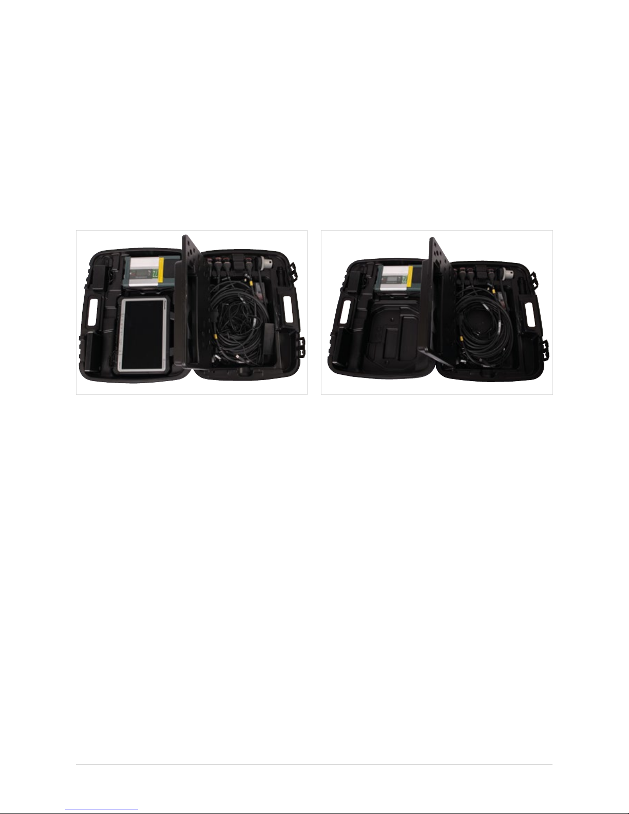
3.1 XENTRY Kit 2 scope of supply
Figure 2: XENTRY Kit 2 scope of supply
Components
XENTRY Tab 2 + country-specic power cable
XENTRY Connect + country-specic power cable
Set of small parts
Ethernet connecting cable 5 m
8-pin, 14-pin, 16-pin, 38-pin cables
User documentation
User guide
User manual for XENTRY systems
Help cards
Panasonic safety information
Accessories
Blu-ray disc drive + power supply unit
XENTRY Kit 2 Software Blu-ray Disc (BD)
3.2 XENTRY Connect scope of supply
Figure 3: XENTRY Connect scope of supply
Components
XENTRY Connect + country-specic power cable
Set of small parts
Ethernet connecting cable 5 m
8-pin, 14-pin, 16-pin, 38-pin cables
User documentation
User guide
User manual for XENTRY systems
Help cards
Accessories
Blu-ray disc drive + power supply unit
XENTRY Kit 2 Software Blu-ray Disc (BD)
9
User Guide XENTRY Kit 2, XENTRY Kit MT 2, XENTRY Connect Daimler AG, Item No. 6511 9538 02, Last updated: 09/2014
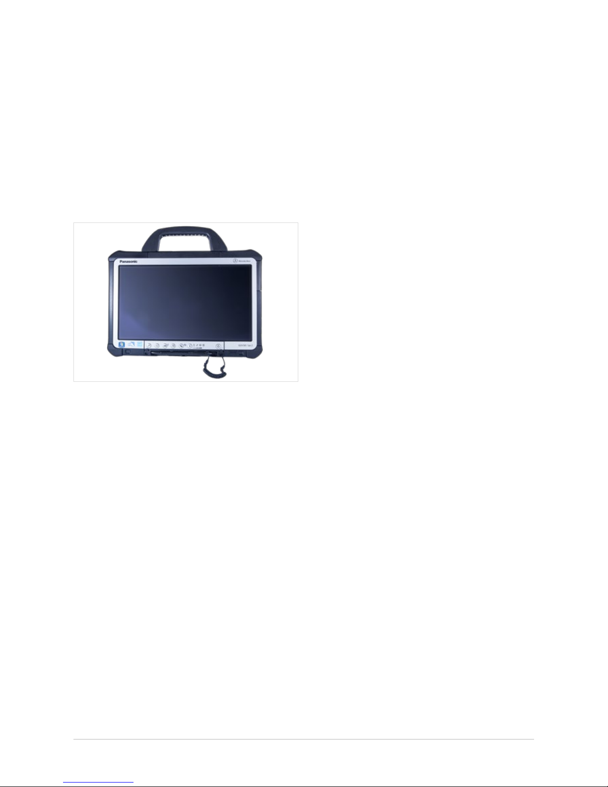
3.3 XENTRY Tab 2 scope of supply
Figure 4: XENTRY Tab 2
Components
XENTRY Tab 2 + country-specic power cable
User documentation
User guide
User manual for XENTRY systems
Help cards
Panasonic safety information
Accessories
XENTRY Kit 2 Software Blu-ray Disc (BD)

10
4 System Requirements and
Network Integration
• XENTRY Kit 2 supports the WLAN standard 802.11a/g/n.
The minimum requirement for the WLAN network is IEEE
802.11g wireless radio operation with a bandwidth of 2.4 GHz.
• We recommend encryption type WPA2 for conguring your
WLAN network. This encryption type oers the greatest
security. Encryption type WEP is no longer supported by
the new product concept.
• Make sure that the WLAN connection between XENTRY
Connect and Access Point is not screened e.g. by vehicles
or metal cabinets.
• If you operate your devices in Service24h mode, please
note that no online connection to back-end systems
(e.g. After Sales Portal, XENTRY Flash, add-ons, etc.)
is available in this mode.
• Make sure that the components' MAC addresses
(XENTRY Connect and XENTRY Tab 2/standard PC) are
enabled for your workshop’s WLAN and LAN on the
DHCP server.
• Please note that the number of systems which can access
the Internet at the same time is restricted in certain
workshops. With the XENTRY Kit 2, two components can
access the Internet. If necessary, clarify this with your
IT manager.
• Please note that you require two LAN sockets plus an
additional LAN cable (recommended length 20 m) per
workstation to operate the devices in workshop mode
via LAN, as only one LAN cable is supplied with the
XENTRY Kit 2. If you only have one LAN jack per workbay,
we recommend the use of a commercially available
LAN hub/splitter.
• When installing printers, make sure that these use
a current Windows 7 printer driver. Only printers
compatible with Windows 7 are supported by the system.
• For the XENTRY Kit 2 to function correctly, a DNS service
must be accessible in the workshop’s network. The
recommended conguration for XENTRY Kit 2 is automatic
procurement of the IP address conguration via a DHCP
server in the internal network. This recommendation
applies in equal measure to both large and small
companies.
• Please ensure that these devices retain a clear line-of-sight
connection to one another at all times, both in the
WLAN (to the access point) and Service24h modes
(to the infrastructure partner) in order that a stable
wireless connection is assured.
Further information on this is also available in the Connectivity Guide in the Mercedes-Benz After Sales portal.
Note: The black Ethernet cable included in the package
contents is a crossover cable. We recommend that you only
use this cable when connecting the XENTRY Connect to
a XENTRY Tab 2 or standard PC, e.g. during conguration.
Please use only this cable for conguration.
11
User Guide XENTRY Kit 2, XENTRY Kit MT 2, XENTRY Connect Daimler AG, Item No. 6511 9538 02, Last updated: 09/2014
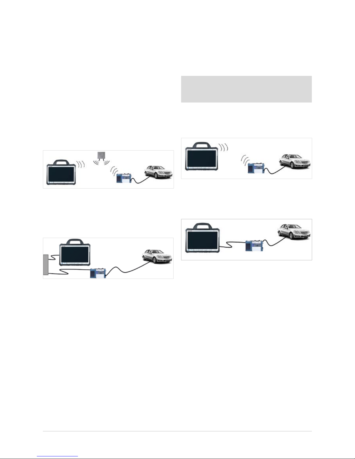
4.1 NetworkProles:ConnectingtheXENTRYConnect
to the XENTRY Tab 2
XENTRY Kit 2 oers two dierent network proles. The work-
shop mode for online connection to the central systems and
the Internet, and Service24h mode without online connection for a direct connection between the devices.
4.1.1 Workshop Mode
XENTRY Kit 2 can be operated in a cable network (LAN)
or in a WLAN network.
• WLAN workshop mode: Workshop IT infrastructure
with Access Point as a base station; both components
are integrated into the infrastructure via WLAN.
Figure 5: WLAN workshop mode
• WLAN workshop mode: Both components are integrated
into the infrastructure via cable. LAN workshop mode
is the alternative if no wireless network (WLAN) is available
or if the quality of the WLAN network is inadequate.
Figure 6: LAN workshop mode
Important: Please note that – in contrast to Star Diagnosis –
you require two LAN sockets and two LAN cables of corresponding lengths per workstation to operate the devices in
this mode. If you only have one LAN jack per workbay, we
recommend the use of a commercially available LAN hub/
splitter.
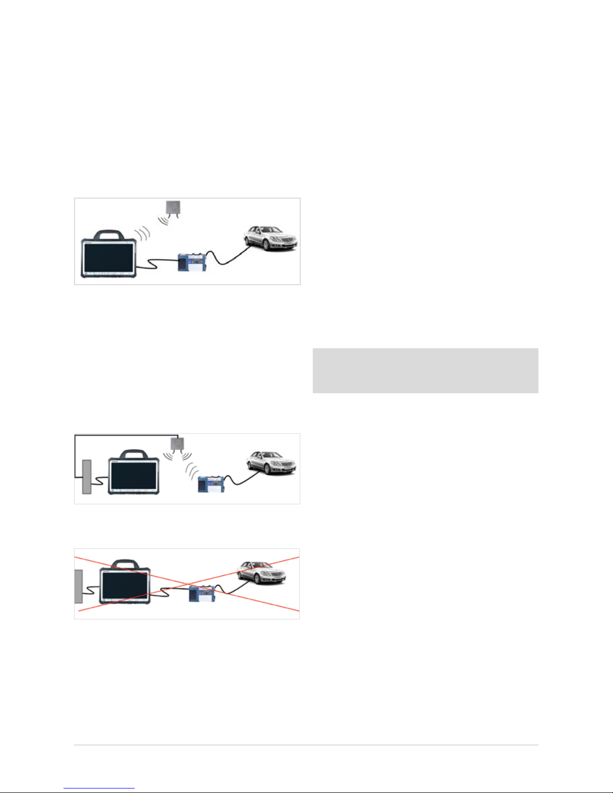
4.1.2 Service24h mode
XENTRY Kit 2 can be connected directly via LAN or WLAN
using the Service24h mode. This may be useful, for example, during use on the road or outside on your company’s
forecourt.
Note: You are not connected to the workshop network in
the Service24h network prole, i.e. you have no back-end
connection (e.g. to central servers for XENTRY Flash).
• Service24h WLAN mode: Direct wireless connection
between XENTRY Tab 2 and XENTRY Connect without
Access Point as a base station.
Figure 7: Service24h WLAN mode
• Service24h LAN mode: The devices are connected via
Service24h mode with a direct cable connection between
the XENTRY Connect and XENTRY Tab 2.
Figure 8: LAN Service24h mode
12
4.1.3 Cabled online mode
In the event that you require an online connection to backend systems, but you want to establish the connection
between XENTRY Tab 2 and XENTRY Connect independent
of the workshop infrastructure, a new mode is now available. It requires using the WLAN workshop mode and thereby
an online connection of the XENTRY Tab 2. To setup the
cabled online mode, connect the XENTRY Tab 2 and XENTRY
Connect to each other using an Ethernet cable and click on
the XENTRY Connect tile in XENTRY Control. This automatically congures thenew mode.
Figure 9: Cabled online mode
4.1.4 Mixed Operation
• WLAN and LAN combined
Workshop mode in mixed operation: E.g. XENTRY Connect
in the WLAN, XENTRY Tab 2 in the LAN. Devices are linked
to each other via the workshop network and are connected
to the back-end systems.
Figure 10: Combined WLAN and LAN
The following connection logic is not possible:
Figure 11: Connection mode not possible
The “serial connection” familiar from Star Diagnosis systems,
i.e. the connection of XENTRY Connect and XENTRY Tab 2 to
the workshop infrastructure via LAN and connection of the
XENTRY Tab 2 via LAN, is not possible.
4.2 Minimum technical requirements and restrictions
on use of a standard PC
A standard PC may be used as an operating and display
unit instead of the XENTRY Tab 2. You are entirely at liberty
to choose the PC manufacturer and model, but must observe
certain minimum requirements.
Minimum requirements:
Operating system: Windows 7 or Windows 8.1(recom-
mendation: Professional 32-bit)
Processor: 1.1 GHz Dual-Core
Hard disk: At least 30 GB available
RAM: 2 GB
USB ports: At least 2 x USB 2.0 (for external
BD drive) or integrated BD drive
Network: LAN and WLAN
Display: Recommended minimum size: 13.3”
Recommended minimum resolution:
1366*768 pixels
Virus scanner: Recommended
.net Framework version 4.0
Note: You will nd the current recommendations
for the minimum requirements of a standard PC in the
Mercedes-Benz After Sales Portal.
Restrictions on use of a standard PC:
• No XENTRY HMS 990 USB Measurement Technology
or chip card reader can be used; the product support
is also limited.
• All Windows updates must be installed independently and as
soon as possible (automatically is best) on the standard PC.
13
User Guide XENTRY Kit 2, XENTRY Kit MT 2, XENTRY Connect Daimler AG, Item No. 6511 9538 02, Last updated: 09/2014
5 Initial Startup and Configuration
Certain steps have to be run through on initial startup of the XENTRY Kit 2.
The HelpCard is also enclosed in the case as a quick guide for initial startup.
5.1 Brief overview of initial XENTRY system startup
1. Unpacking the devices: Remove the XENTRY Tab 2 and
the XENTRY Connect from the case. We recommend fully
charging the rechargeable batteries in the XENTRY Tab 2
and the XENTRY Connect once prior to initial startup.
To do this, connect the enclosed power supply units to
the relevant device. Initial startup can be started while
both devices are still charging. However, make sure that
the power supply is not interrupted at any time.
2. Enable the WLAN MAC addresses for the XENTRY Tab 2
and XENTRY Connect for your network. To do this, please
contact your IT administrator or IT service provider.
You will nd the MAC addresses on the adhesive labels
on the back of the XENTRY Tab 2 and XENTRY Connect.
Figure 12: Adhesive label with MAC addresses
Now ll out the network questionnaire that is enclosed
in the case together with your IT administrator.
Do not proceed with the initial startup until you have fully
completed the questionnaire! This allows you to avoid
additional work.
3. The software on the XENTRY Connect is pre-installed. The
standard XENTRY Connect language on delivery is always
English. You can change the language when connecting
the device to the XENTRY Tab 2 for the rst time.
4. XENTRY Control software is used to congure the
XENTRY Tab 2 and the XENTRY Connect for your
workshop network. CongAssist, which is integrated there,
guides you step-by-step through the process. CongAssist
opens automatically after starting XENTRY Control; if not,
it can be launched manually using the “Conguration”
menu.
5. Now, please order a StartKey and enter it into your
system so that you are able to use the XENTRY
Diagnostics/XENTRY DAS diagnostic software.
StartKeys are ordered through the already familiar tools
and channels; if necessary, inquire in your market.
Note: WIS/ASRA is only available via the central installations in on-line mode. This also ensures that you enjoy all of
the advantages of online operation on the diagnostic
systems, such as e.g. the latest documents
at all times. Of course, WIS/ASRA can still be accessed
from the XENTRY frame, so that transfer of the vehicle
context is always assured. If access to a central installation
is not possible or permitted, WIS/ASRA may also
be ordered as a WIS/ASRA standalone (i.e. oine including
updates via DVD) in exceptional cases. Use the standard
channels to order a WIS/ASRA StartKey in these situations.
However, orders can only be placed if a corresponding reason
is specied. With this variant, you receive the same monthly
WIS/ASRA DVD as for Star Diagnosis systems. Please
contact your market representative for further information.
14
Figure 13: Start screen for conguration with CongAssist
The following screen will appear after you have selected
the conguration type:
Figure 14: Network questionnaire access screen
Here, you can call and print out the network questionnaire.
A printout of the network questionnaire can also be found in the
case. All important data on the workshop network, e.g. network
name and key, proxy settings, etc., can be documented on the
network questionnaire in advance. If necessary, ask the
IT administrator in your facility for the required data.
Then continue to follow the dialogs in CongAssist to congure both devices. The network questionnaire data are queried
step by step.
5.2 Congurationoftheoverallsystem
You have two conguration options: “Dialog-guided” (CongAssist) or by means of the “Expert dialog”. If you work with
xed IP addresses, please congure these via the DHCP
server. If, in exceptional cases, this is not possible, you
can congure it by means of the Expert dialog.
5.2.1 Conguration(dialog-guided,CongAssist)
You need the lled-out network questionnaire for the following conguration. Please have your completed
network questionnaire ready.
Start XENTRY Control using the desktop link
on your XENTRY Tab 2.
Note: If you are using a standard PC, a dialog for the deskband pop-up is shown here. Please conrm this dialog with
“Yes”.
CongAssist opens automatically after starting XENTRY
Control; if not, it can be called using the “Conguration”
menu. Check the external power supply to the XENTRY Tab 2
and XENTRY Connect.
Switch on the XENTRY Connect. To switch on the XENTRY
Connect, press any button on the XENTRY Connect operating
panel. Then, the message “Start XENTRY Connect?" appears
in the display. Conrm this message with the green tick. The
XENTRY Connect will start.
During the startup process for the XENTRY Connect, the
message “Device is starting” will appear in the display. Wait
until the XENTRY Connect startup process is complete and the
ready LED is green. During the initial start, this can take up to
10 minutes. Please follow the dialogs on the XENTRY
Tab screen.
The rst dialog in XENTRY Control oers you three selection
options for beginning the conguration:
1.) New, without any existing conguration data
for the initial startup.
2.) Based on an existing conguration le,
e.g. upon replacement.
3.) Based on this XENTRY Tab 2/standard PC,
e.g. with a new XENTRY Connect.
Click the option that best suits your case. If you do not have
any information on this, in the rst CongAssist dialog select
the option “New, without existing conguration data” for the
initial startup.
15
User Guide XENTRY Kit 2, XENTRY Kit MT 2, XENTRY Connect Daimler AG, Item No. 6511 9538 02, Last updated: 09/2014
1. First, select the basis for the conguration.
Figure 15: Selecting the components for the conguration
In case of an initial startup, select “Congure overall sys-
tem”.
2. A series of numerous queries follows; please enter
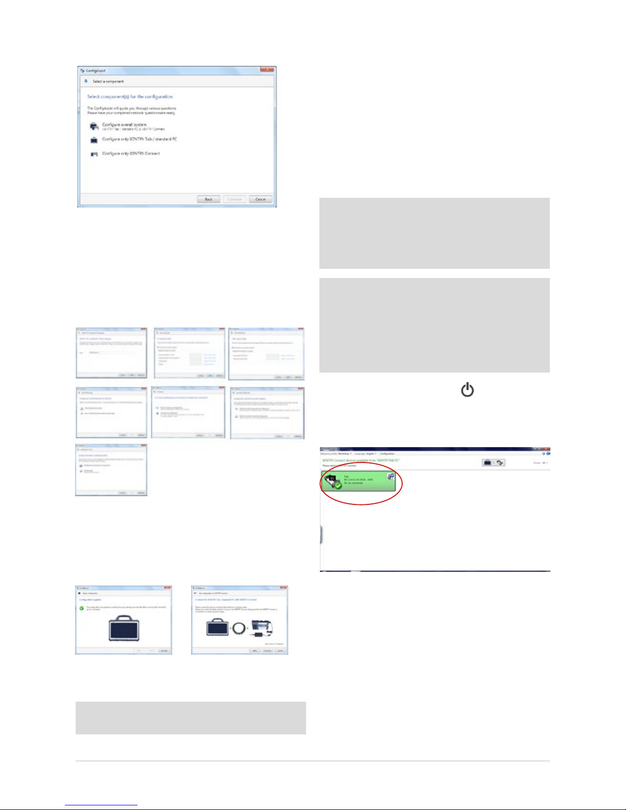
the data and/or make the selections that your
IT administrator has noted on the network questionnaire.
Figure 16: Cong Assist dialog sequence for the initial startup
3. After the input has been entered, you can choose whether
the data should rst be saved in a le or immediately
applied to the XENTRY Tab 2 and the XENTRY Connect.
Select an option and proceed with the dialogs.
Figure 17: Apply conguration and successful conguration at completion of
Cong Assist.
Tip: Save the le so it can also be used for additional devices as a conguration le.
Now connect the XENTRY Connect with the XENTRY Tab 2
using the provided black Ethernet connecting cable, and
screw on the cable to the XENTRY Tab 2. On completion of
conguration, the XENTRY Connect display or the XENTRY
Control tile will show the message “Conguration success-
fully applied”.
The conguration wizard can be ended and the connection
between the two devices separated. To do this, simply disconnect the black Ethernet connecting cable from
both devices.
Note: If you work with xed IP addresses, we generally recommend that you set up a conguration via a DHCP server.
From an IT operations perspective, this is the most secure
way to ensure a sound and stable operating environment.
Details on DHCP can be found in the Connectivity Guide.
Note: If you do not use a DHCP server or, due to network
problems, you wish to assign static IP addresses for your
XENTRY Kit 2, you can also carry out the conguration via
XENTRY Control. In this case you must transfer the conguration to the XENTRY Connect by means of a USB memory
stick. To do this, save the conguration le on
a USB memory stick and insert it in XENTRY Connect.
Then check whether the “Ready” icon
appears in the
XENTRY Connect display and if the XENTRY Connect is shown
in green in XENTRY Control after about 10 seconds.
Figure 18: XENTRY Control Selection Screen
If yes, you may now use the XENTRY Connect to work on
the vehicle together with the XENTRY Tab 2. To do this, click
onto the green XENTRY Connect icon to connect to it.
If no, there are two possible remedies.
16
a) The XENTRY Connect icon is shown in gray in XENTRY
Control and the gears ash on the display:
Figure 19: XENTRY Control tile “Not congured”
In this case, repeat conguration as described in these
instructions. Note that CongAssist is now no longer
started automatically. Open CongAssist using the menu
bar in XENTRY Control in the “Conguration” menu item.
Please contact Diagnosis Support if a subsequent attempt
also fails.
b) XENTRY Connect does not appear any more in the
overview: in this case, check whether both devices are
set to the same network prole: workshop or Service24h
mode. This can be checked in XENTRY Control through
the menu
“Network prole” Service24h and by using
the gear button on the XENTRY Connect. If the XENTRY
Connect is still not displayed, then prior to reattempting
conguration the XENTRY Connect and the XENTRY Tab 2
must be connected directly using the Ethernet connecting
cable and Service24h mode must be set in each case.
Only then is it possible to perform conguration again
using CongAssist.
Note: After removing the black Ethernet connecting cable,
the devices are only connected if the WLAN is activated
and congured, i.e. if WLAN conguration has been executed in CongAssist.
Please contact Diagnosis Support if a subsequent attempt
also fails.
5.2.2 Expert mode initial startup
In contrast to the procedures described above, this initial
startup procedure is not guided and you must enter the
required data yourself. We only recommend using this
procedure if you have extensive technical knowledge and
have already congured such devices in the past. Keep your
workshop-specic network data ready, e.g. the IP address,
network name and key, as these are required to ll in the
screen. This section only explains the dierences between
expert conguration and initial startup using CongAssist.
The expert dialog is also called using the “Conguration”
menu item in the XENTRY Control software. Then click onto
the blue “Expert conguration” link at the bottom right in
CongAssist:
Figure 20: Accessing the conguration with the Expert dialog
The following window will open:
Figure 21: Expert dialog
The expert dialog is subdivided into the 3 “Workshop”,
“XENTRY Tab 2/standard PC” and “XENTRY Connect” tabs.
First switch to the “Workshop” tab at the top and then to the
“WLAN settings” panel. Make sure that the WLAN (global)
is set to “On”.
Figure 22: Expert dialog: WLAN settings
Fill in the elds required for your workshop. Enter the
individual values for your workshop in the proxy settings,
search for settings, EPC, WIS/ASRA settings and group
17
User Guide XENTRY Kit 2, XENTRY Kit MT 2, XENTRY Connect Daimler AG, Item No. 6511 9538 02, Last updated: 09/2014
settings tabs. If you would like to use groups, these must be
created in the group tab so that they can be subsequently
assigned to the XENTRY Connect devices.
This may be helpful if you use a number of XENTRY Connect
devices in your company or the company is subdivided into
dierent teams. The denition of groups oers a more clearly
arranged display in XENTRY Control.
Example: Team 1 Cars, Team 2 Trucks
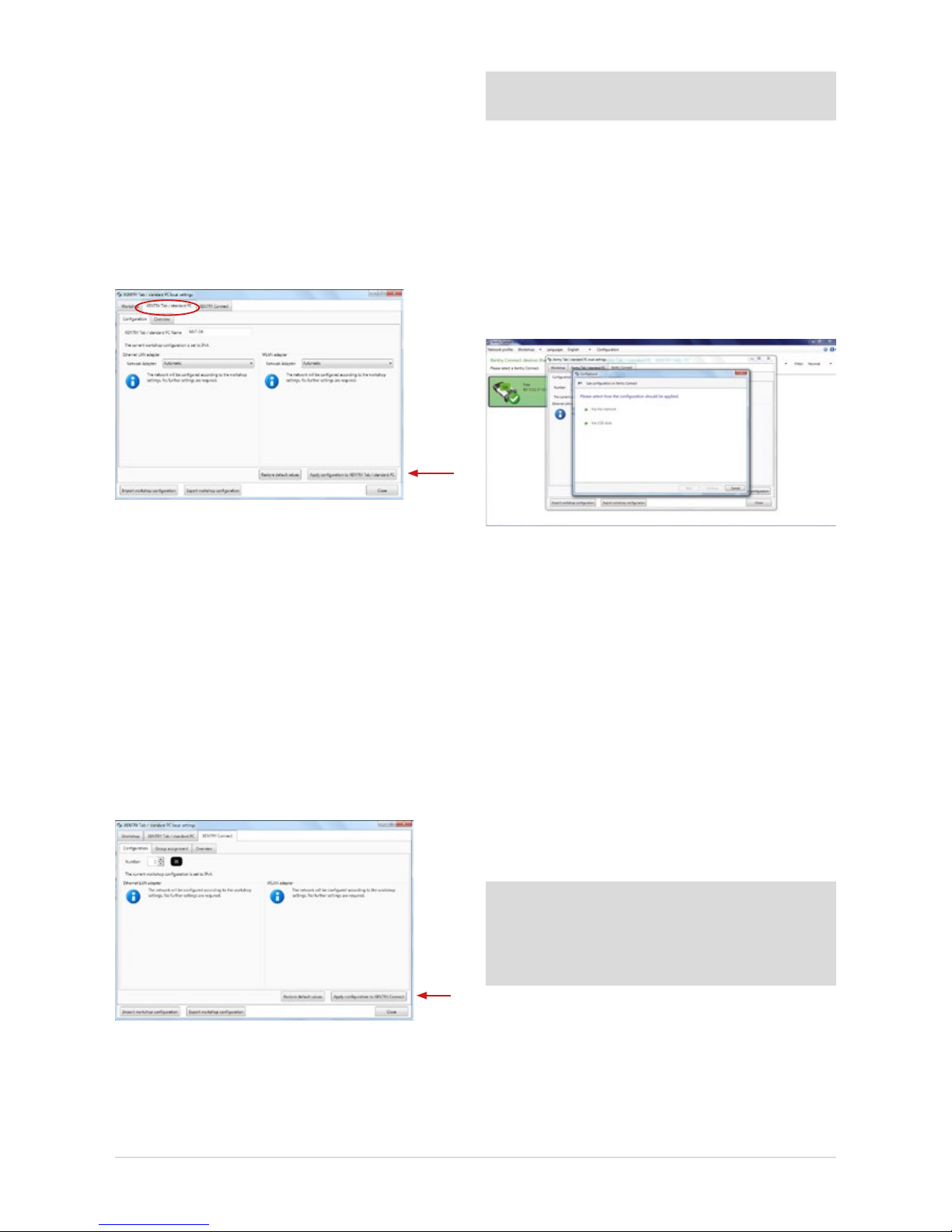
Now switch to the “XENTRY Tab 2 / standard PC” tab:
Figure 23: Expert dialog: Apply XENTRY Tab 2 conguration
Fill in the following elds in the “XENTRY Tab 2 / standard PC”
tab:
• The name of the XENTRY Tab 2 must be entered
(without blanks) in the “Conguration” tab
• An overview of the input data is displayed in the
“Overview” tab
• Finally, press the “Apply conguration to XENTRY Tab 2 /
standard PC” button
The following message appears: “Please wait while the
conguration is applied to the XENTRY Tab 2.” The message
“Conguration successfully applied” appears after a while.
Now switch to the “XENTRY Connect” tab:
Figure 24: Expert dialog: Apply XENTRY Connect conguration
Please enter the desired number of the XENTRY Connect in
the “Conguration” tab.
Important: Each number may only be assigned once in
your workshop!
• The groups previously dened for your workshop
operation in the “Workshop – groups” tabs can be
assigned to the XENTRY Connect. A list containing
the dened groups appears.
• An overview of the input data is displayed in the
“Overview” tab.
• Finally, press the “Apply conguration to
XENTRY Connect” button.
The following dialog will appear:
Figure 25: Expert dialog: Conguration type prompt
Here, you may select whether you want to carry conguration out “Via the network” (using the
Ethernet connecting cable) or “Via USB stick”.
“Via the network” means that conguration is carried out
using the Ethernet connecting cable by which the XENTRY
Tab 2 is connected to the XENTRY Connect.
“Via USB stick” means that conguration is carried out
by saving the conguration le to a USB stick, which has
to be inserted into the XENTRY Connect.
If you want to perform the conguration by means of a USB
memory stick, save the le onto the stick by clicking “Via
USB memory stick”; continue to follow the dialog prompts.
Note: The conguration le must be saved on the USB memory stick in the directory VCI_VIEW/cong; this directory
is automatically created by XENTRY Control. Please do not
change the name of the le. Otherwise,
the le cannot be read.
Now insert the USB memory stick into the XENTRY Connect.
The XENTRY Connect must be switched on. Then press the
“green check” and “red cross” buttons simultaneously. In
the display your are asked “Start conguration?", conrm
this with the 'green check-mark'. The conguration will be
initiated; the XENTRY Connect LED will ash green.
18
On completion of the conguration, you will see the message
“Conguration applied successfully” in the XENTRY Connect
display. Please remove the USB memory stick from the XENTRY
Connect. The conguration is now nished.
If you select “Via the network”, the message “Please connect
the XENTRY Tab 2 to the XENTRY Connect using the Ethernet
connecting cable” appears after clicking on “Continue”. Check
whether both devices are correctly connected via the Ethernet
connecting cable. The message “Conguration successful”
appears after a while. You are now nished conguring the
XENTRY Connect. Then restart both devices and wait until
both have completely booted. Check then if the “Ready”
symbol is shown on the display of the XENTRY Connect
and if the XENTRY Connect is shown in green after the
XENTRY Control software has been started:
Figure 26: XENTRY Control Selection Screen
If yes, you may now use the XENTRY Connect to work on the
vehicle together with the XENTRY Tab 2. To do this, click onto
the green XENTRY Connect icon to connect to it.
If no, there are two possible remedies.
a) The XENTRY Connect icon is shown in gray in XENTRY
Control and the gears are ashing on the display:
Figure 27: XENTRY Control tile “Not congured”
In this case, repeat conguration as described in
these instructions. Please contact Diagnosis Support
if a subsequent attempt also fails.
b) XENTRY Connect does not appear any more
in the overview:
In this case, check whether both devices are set to the
same network prole: workshop or Service24h mode.
If this does not remedy the problem, the XENTRY Connect
and the XENTRY Tab 2 must be connected directly using
the Ethernet connecting cable prior to reattempting
conguration, and Service24h mode must be set on each
device. This is carried out in XENTRY Control using the
menu
“Network prole” Service24h, and by using the
gear button on the XENTRY Connect , which you
press until the message “Switch to 24h mode?" appears
on the display. Conrm this message with the green tick.
Only then is it possible to perform conguration again.
Please contact Diagnosis Support if a subsequent attempt
also fails.
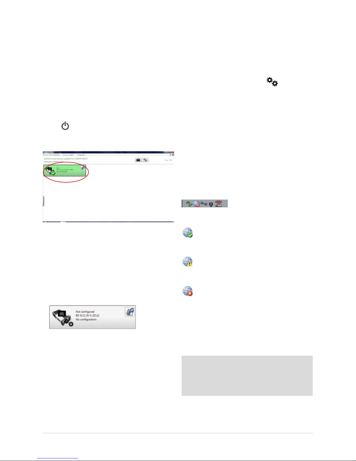
5.3 CheckingtheBack-endConnections
Whether the back-end connections (i.e. WIS, EPC, TIPS, VeDoc,
XSF, LogCollect/AQUA, XENTRY Flash Server) or Internet
connections are functioning correctly can be seen
at the bottom of the deskband when you are connected to your
XENTRY Connect.
Figure 28: Deskband
A globe with a green check-mark, indicating that all
back-end connections are accessible, appears in the
deskband.
If the globe is displayed with a yellow exclamation
mark, this means that only certain back-end
connections are available.
If no back-end connection is available, the following
icon will appear in the deskband:
In this case, please check whether the device is correctly
congured for your workshop and whether you are able to
establish an Internet connection at all. To test this, you can
open the XENTRY browser and e.g. call the After-Sales Portal
under favorites. If the homepage appears, you may assume
that the Internet connection is functioning correctly.
Note: As soon as XENTRY Tab 2 accesses the Internet for
the rst time, the Windows 7 updates are downloaded. This
can take a while. The XENTRY Connect is provided with the
Windows 7 updates via the “XENTRY Kit 2 Software Blu-ray
Disc”.
If no Internet connection is available, please check whether
the devices have been correctly congured for your
workshop. The data which you have input can be checked
19
User Guide XENTRY Kit 2, XENTRY Kit MT 2, XENTRY Connect Daimler AG, Item No. 6511 9538 02, Last updated: 09/2014
by calling up the menu in XENTRY Control: Conguration
Check Expert dialog. One further reason may be that
the XENTRY Connect and/or XENTRY Tab 2 have not been
enabled for your workshop network. In this case, ask your IT
manager / workshop network service provider.
5.4 Order StartKey
On completion of conguration, you must order the necessary StartKeys to be able to use the XENTRY system. The
StartKey enables you to use the XENTRY Diagnostics and
XENTRY DAS diagnostic applications. You also require an
additional StartKey to use WIS standalone. Please note that
the use of WIS standalone is only now approved in exceptional cases. Make sure that an Internet connection
is available and carry out the following steps:
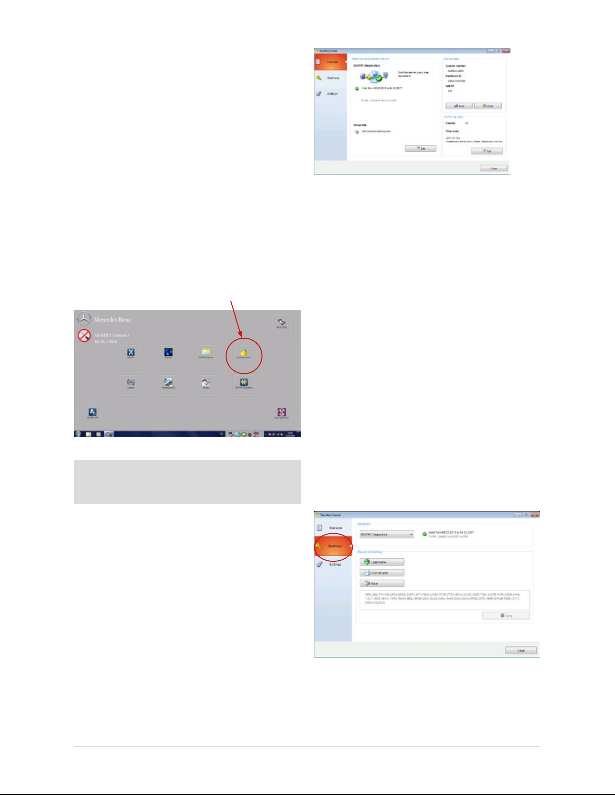
1. Connect to the XENTRY Connect. Start the StartKey Center
using the button on the adjacent Diagnosis desktop.
Figure 29: Diagnosis desktop on the XENTRY Connect
Note: A temporary StartKey is no longer available on the
XENTRY Connect! Please order the StartKey in a timely
manner.
2. Read out the HW ID and system number of your
XENTRY Connect in the “Overview” tab. You require this
information to order the StartKey.
You have the option of saving the values by means of
“Copy” and/or “Save” buttons to save the values and
make it easier for the StartKey order to read them in.
Figure 30: StartKey Center overview
3. We would like to point out our electronic ordering options
(LOP, LOT) to apply for permanent access authorization
(StartKey). Information on which ordering process is used
in your country (LOP, LOT or ordering through a central
national contact person), is available from the contact
person for access authorization/StartKeys at your
national company.
4. Now open the “StartKeys” tab. You now have three
options for reading the StartKey for XENTRY Diagnostics
into your system.
a) You save the attached le (which you received via email)
on a USB memory stick in the root directory, then insert
it in the XENTRY Tab 2 and read in the StartKey in the
StartKey Center from the USB memory stick.
b) Then open the StartKey Center and click on the “Load
StartKey online” button. The StartKey is then read-in
directly online. For this variant, you must make sure
that the XENTRY Connect has an Internet connection.
c) You manually enter the StartKey.
Figure 31: Screen for entering StartKeys
20
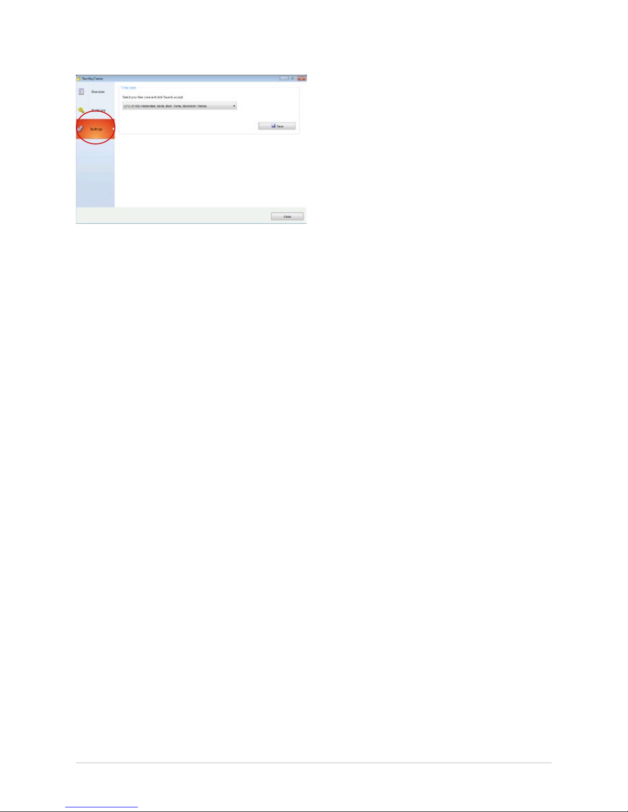
5. Then, specify your time zone in the “Settings” tab
and save them by means of the “Save”.
Figure 32: Settings screen in the StartKey Center
You may now start XENTRY Diagnostics. You can now also
use XENTRY Diagnostics in the Service24h mode.
21
User Guide XENTRY Kit 2, XENTRY Kit MT 2, XENTRY Connect Daimler AG, Item No. 6511 9538 02, Last updated: 09/2014
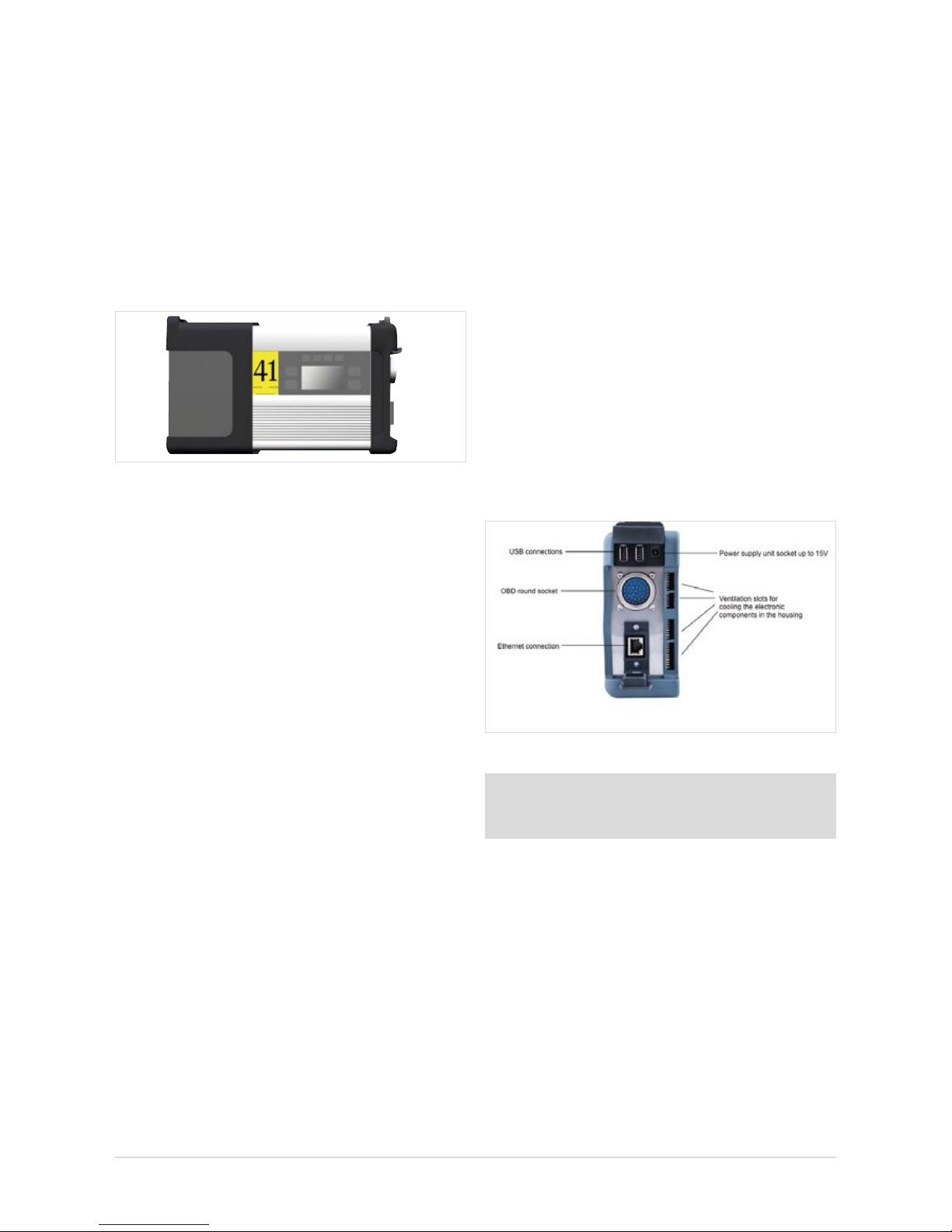
6 XENTRY Connect
As the successor to SDconnect, the XENTRY Connect oers
an autonomous PC core in addition to the multiplexer properties.
Figure 33: XENTRY Connect
The following points provide a brief overview of the properties
and performance features of the XENTRY Connect:
• The core element is a PC with an SSD as a robust storage
medium on which the diagnostic programs are executed.
• The power supply for the XENTRY Connect occurs:
- Directly through the vehicle’s diagnostic socket (OBD)
- Via the battery in the absence of an on-vehicle supply
- With the aid of an external power supply unit included
in the delivery scope
• The connection with the XENTRY Tab 2 is carried out:
- Wireless: via WLAN; a WLAN module is installed
- Cable-based: using the Ethernet connecting cable
included in the delivery scope
6.1 Technical Performance Features
Operating system: Windows Embedded Standard 7 (32-bit)
Processor:
B810 CPU (Core2Duo 2nd gen., 2x 1.6 Ghz)
RAM: 4 GB
Data storage: 256 GB SSD
Display size: 128x64 px
Battery operating
time:
40 minutes with 60% CPU load
USB interfaces:
2 x USB 2.0
Weight (incl. battery):
1.9 kg
Protection class: IP 54
Other interfaces:
WLAN interface
Warranty: 3.5 years (battery warranty: 6 months)
Number of batteries:
1
WLAN standard: IEEE 802.11 a/b/g/n 2.4 + 5 GHz
Certications: CE, UL, GOST-R, KCC, FCC, VCCI, WLAN
The XENTRY Connect is supplied with the WLAN module
deactivated in all non-certied countries. When operated in
these countries, we recommend the use of a “micro stick”
(e.g. D-Link DWA-131/D-Link DWA-121) to nevertheless
enable you to work in the WLAN. If the D-Link stick DWA131/D-Link DWA-121 is not available in your country, please
contact the Diagnosis User Help Desk.
6.2 Interfaces on the XENTRY Connect
Figure 34: Connection options on XENTRY Connect
Note: Please make sure that the fan at the rear of the
XENTRY Connect is always free and that the XENTRY
Connect is not positioned lying on its fan in the vehicle.
6.2.1 Socket for the XENTRY Connect power supply unit
Used for the operation of a XENTRY Connect device via the
mains supply if it is not connected to a vehicle with the round
plug and not supplied by the vehicle battery. Only the power
supply unit included on delivery may be used.
6.2.2 USB Connections
The USB jacks are used to connect the Blu-ray drive from MoTelDis, the RS232 adapter for using the SBC ash box, for USB
sticks or other USB 2.0 devices approved by Daimler AG. The
power supply delivers max. 500 mA. The connection
of a keyboard or a mouse is not supported.
22
6.2.3 Connecting XENTRY Connect to the vehicle (cable)
A XENTRY Connect device can be connected to the vehicle
using various vehicle-specic connecting cables. The cables
are compatible with the current vehicle cables and are
connected to the XENTRY Connect using a so-called
push-pull mechanism.
Note: Please note that the XENTRY Connect must always
be supplied with sucient power when used in the vehicle.
When working on the vehicle, always connect an external
power supply to the vehicle (> 12.5 V).
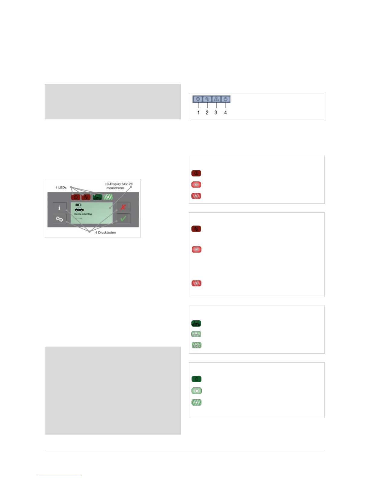
6.3 XENTRY Connect operating panel
As is already familiar from SDconnect, the XENTRY Connect
oers a display and four buttons for operation. Two green
and two red LEDs for indicating the current operating status
are new.
Figure 35: XENTRY Connect operating panel and display
6.3.1 Button Lock on the XENTRY Connect
The XENTRY Connect is equipped with a button lock so that
it cannot be switched on unintentionally during transport or
daily operations. If you wish to switch the XENTRY Connect on,
press any button on the operating panel. The prompt “Start
XENTRY Connect?" then appears on the display. Conrm this
by pressing the green tick on the operating panel. The XENTRY
Connect starts after pressing the green tick.
Note: If the XENTRY Connect is stored for longer than
50 days without external supply voltage (connection to
a vehicle or external power supply unit), this will cause the
complete shutdown of the XENTRY Connect in order to
prevent a deep discharging of the battery. In this operating
state the display is switched o and the XENTRY Connect
device does not react any more to the pressing of a button.
A restart of the device and consequently the reactivation
of the display and keypad is accomplished by connecting
it to the power supply unit included in the delivery scope.
Recharge the device completely.
6.3.2 LEDs and Search Tone
To indicate dierent status and event information, the
XENTRY Connect is equipped with two green and two red
LEDs as well as an acoustic search tone. If the search tone
is activated, all LEDs ash simultaneously for the dened
time period of 10 seconds and a signal tone is sounded
on the device at the same time.
Depending on status (o, on, ashing), the LEDs have
dierent meanings; these are described in detail in the
following.
1 = Malfunction LED (red) 3 = Network LED (green)
2 = Occupied LED (red) 4 = Power LED (green)
Malfunction LED (red)
OFF No fault found
On Device fault found on the XENTRY Connect
Flashing
XENTRY Connect battery is almost empty
Occupied LED (red)
Network LED (green)
O No network connection available
On Network connection exists
Flashing
A network connection is being established
O XENTRY Connect is unused
and can be used
On XENTRY Connect is operating and cannot
be used (XENTRY Tab 2 is connected or an
independent process, such as an update,
is running)
Flashing
The XENTRY Connect is blocked by
a
XENTRY Tab 2 that is not currently connected.
Power LED (green)
O XENTRY Connect is switched o
On XENTRY Connect is operational
Flashing
XENTRY Connect is booting or
has not yet been congured
23
User Guide XENTRY Kit 2, XENTRY Kit MT 2, XENTRY Connect Daimler AG, Item No. 6511 9538 02, Last updated: 09/2014
Figure 37: Battery statuses of the XENTRY Connect
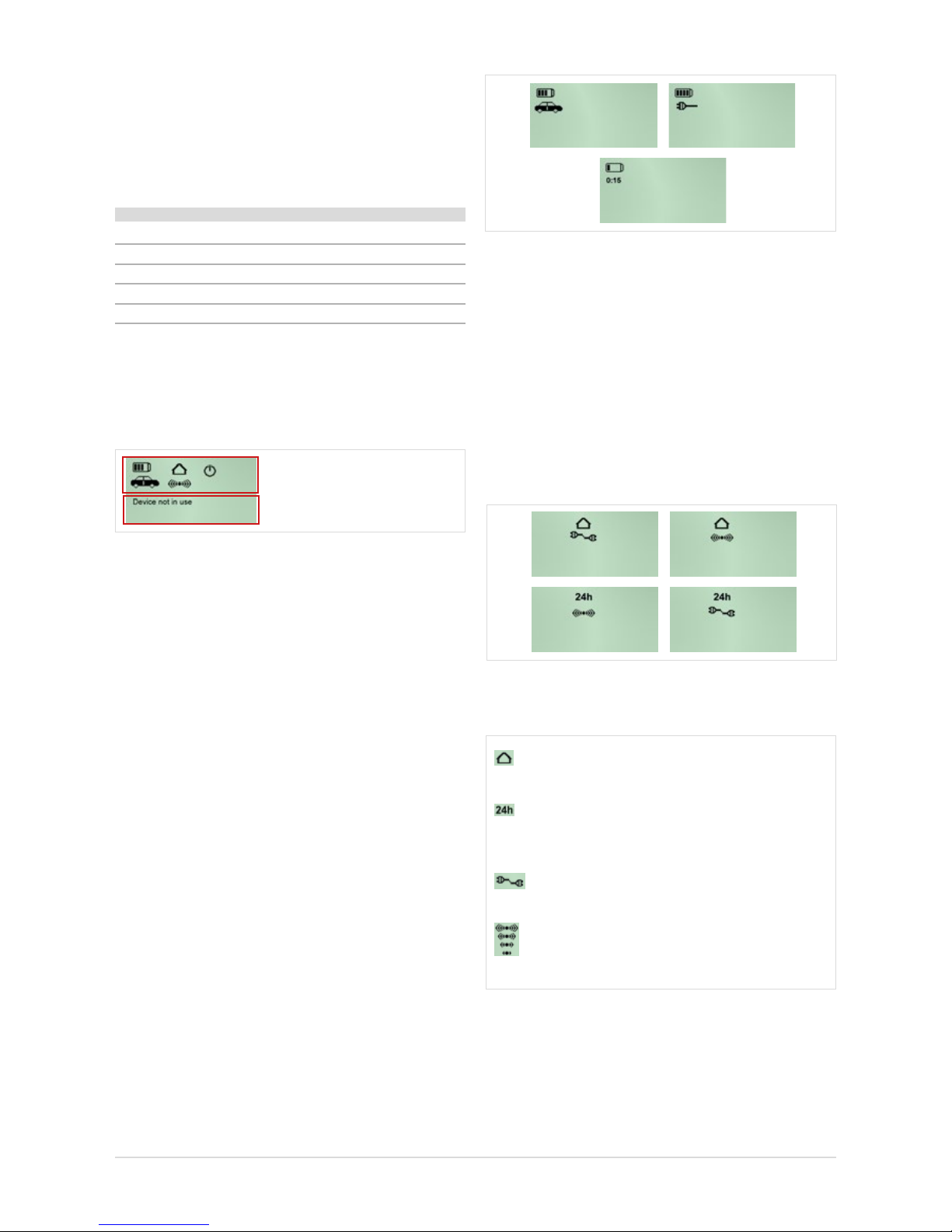
Connection icon: connection status and quality
The house display and the 24h icon clearly indicate
which network prole is active.
The house symbolizes the workshop network. The 24h icon
shows that the devices are directly connected, e.g. for breakdown assistance. If a cable is displayed beneath,
this means that the connection has been established using
a cable. If the WLAN icon is displayed, this means that
the connection is wireless.
Figure 38: Network prole statuses of the XENTRY Connect
These symbols indicate the type and quality of connection.
stands for the workshop network prole (connection via a network)
stands for the Service24h network prole
(direct connection without network, similar
to the current road mode)
stands for a cable connection
(to the XENTRY Tab 2 or the workshop network)
stands for a WLAN connection: the number of
radio waves (one to four) shown in the relevant icon
represents the signal strength of the WLAN signal.
Figure 39: Key to icons: “Workshop”, “24h”, “LAN” and “WLAN”
Acoustic signal
Depending on the status of the device, the search tone
provides an acoustic signal which diers in terms of length
and repetition frequency. There are several statuses which
are indicated:
Status Sound
Startup process/switched on short 1x
No external power supply is currently present short
1x
Power supply switchover short 1x
Battery is almost empty short 3x
“Key Finder” activated 3x long
6.3.3 Display
The display is used to show all information that is relevant to
the user. The display is divided in an upper and lower section.
Upper section: Status icons
Lower section:
Additional information
Figure 36: Display of the XENTRY Connect
a) The upper half of the display serves to show status icons.
These are displayed permanently and updated as required.
They indicate the battery condition, type of connection,
and the operating state of the device.
b) The lower area is used for messages regarding the
properties, name and statuses of the device and
its connections as well as information to explain and
operate the available options.
6.3.4 Upper section of the XENTRY Connect display
Battery icon
The number of bars (zero to four) in the battery can be used
to determine the charge level of the rechargeable battery.
A vehicle or connector shown underneath indicates that there is a connection to the vehicle or another external power
supply, and that the rechargeable batteries are charging. If
there is no external power supply, however, the duration in
minutes until the XENTRY Connect automatically switches to
standby is located beneath the battery icon.
24
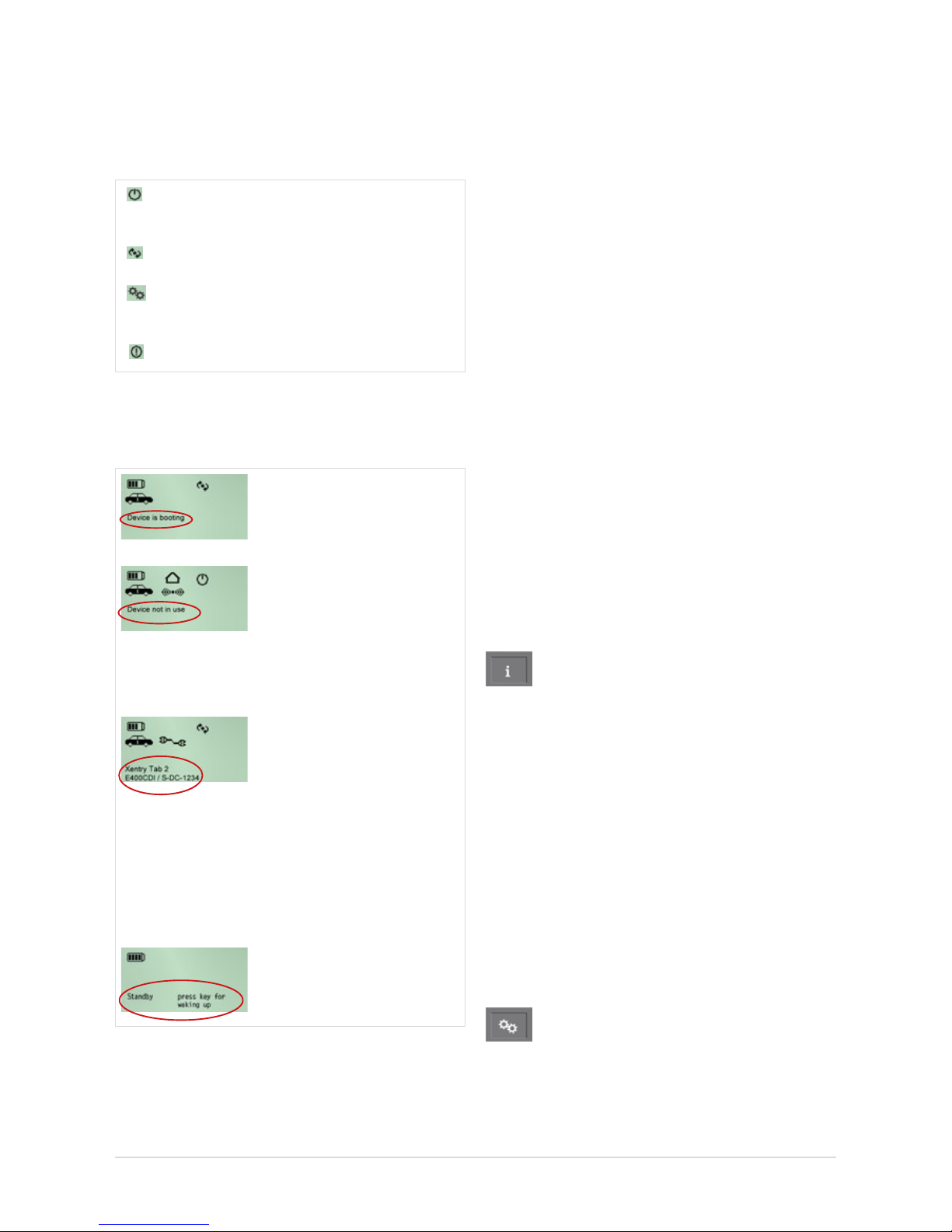
Operational status: Working status
The icons in the upper area of the display indicate whether a
XENTRY Connect is available or has already been occupied
by another XENTRY Tab 2, or whether a defect is present.
The XENTRY Connect is ready (the icon ashes while
the device is starting)
Device is occupied and currently operating.
Initial startup (icon ashes if the device is not con-
gured)
Defect/malfunction
6.3.5 Lower section of the XENTRY Connect display
Examples
The “Device is booting” message appears during the booting
process.
With the OBD power supply
connected yet without acti-
ve application, the message
“Device is not in use” appears
and the currently installed BD
version is displayed.
If a power supply is connected
and an application is active,
a message generated by the
application is displayed. If
the device is connected to a
XENTRY Tab 2, the name of the
connected XENTRY Tab 2 is
shown above the name of the
application (in the example,
“XENTRY Tab 2 1”).
The device is not in use and is
set to standby.
Figure 40: Text and notes in the XENTRY Connect Display.
6.3.6 Background Illumination Statuses
The background illumination of the display has three operating states: ON, OFF and ashing.
• Background illumination ON indicates that the device has
recently been activated or a button has recently been
pressed.
• Background illumination OFF can be attributed to two
causes:
- If nothing is shown on the display at all any longer, the
device has no power supply. The rechargeable battery is
also empty or has been removed.
- When output is shown on the display (a), the XENTRY
Connect is either in standby or (b) no XENTRY Connect
buttons have been actuated within approx. 4 minutes, or
the information has not been updated/changed within
approx. 4 minutes.
• Background illumination FLASHING indicates that the
search tone is active.
6.3.7 Buttons of the XENTRY Connect
The XENTRY Connect oers the user the following four
buttons to operate the display and a button combination to
carry out updates.
Information button
This button guides you through an information menu and
displays the following information in succession:
• Diagnosis update version: Blu-ray Disc (BD) x/xx
• Vehicle battery voltage
• XENTRY Connect serial number
• Name of the connected XENTRY Tab 2
• Fault information
• Network information
- WLAN: MAC, DHCP status
- WLAN: IP, subnet
- WLAN: gateway, status
- WLAN: SSID, encryption
- LAN: MAC, DHCP status
- LAN: IP, subnet, gateway
Function buttons
This button can be used to access functions that are relevant
to the current device status; other functions will not be oe-
red (dynamic menu).

25
User Guide XENTRY Kit 2, XENTRY Kit MT 2, XENTRY Connect Daimler AG, Item No. 6511 9538 02, Last updated: 09/2014
The following functions are available:
• Change (W)LAN mode
• Release device – after additional conrmation request
• Start network self-test
• Switch o device – after additional conrmation request
• Activate / deactivate Automatic Quick Test Routine (AKT)
Back/cancel button
Back: press button < 2 seconds
Cancel: press button > 2 seconds
Conrmbutton: OK / Yes
Key combination
When the device is switched on ▸ start the initial startup
process with the USB memory stick
When the device is switched o ▸ Start update/recovery
Depending on precondition, the back/cancel button and
conrmation button combination (pressed for two seconds)
triggers dierent actions:
•Whenthedeviceisswitchedon,theinitialstartup
process starts:
When the device is switched on, pressing the cancel and
conrmation buttons at the same time for two seconds
starts the initial startup process. Details can be found in
the chapter 5 Initial Startup and Configuration.
•Whenthedeviceisswitchedo,update/recovery
starts:
When the device is switched o, pressing the cancel and
conrmation buttons at the same time for two seconds
switches the device on and starts the update process.
Details can be found in the chapter 11 Update & Recovery.
6.4 Starting and Shutting Down the XENTRY Connect
A XENTRY Connect is started by pressing its operating
buttons or by connecting an OBD power supply. The device is
fully booted when the “Ready” icon
is continually shown
on the display. Shutting a XENTRY Connect down to standby
is carried out using the operating menu function button.
If a user is still connected to this XENTRY Connect at this
point in time, this visual connection is ended in a controlled
manner with a corresponding notice message. If a XENTRY
Connect is shut down unexpectedly, e.g. due to a crash or
the absence of a power supply, currently connected users
receive an error message.
6.5 Battery Compartment
The cover of the rechargeable battery compartment can be
opened (by releasing four screws) to exchange the recharge-
able battery if necessary. Remove the rubber bumper to do
this.
Figure 41: XENTRY Connect
battery compartment
This compartment contains a rechargeable lithium-ion battery block. In addition to cells, electronic protection devices
and intelligent battery management, it also has non-elec-
tronic protection devices and mechanical components.
The battery has a rated voltage of 7.2 volts and a maximum
capacity of 4.5 Ah.
Note: Please do not frequently remove the rechargeable
battery! Please follow the instructions. Do not open the
battery compartment or exchange the rechargeable battery
while the XENTRY Connect is connected to a vehicle or a
diagnostic process is running. Only open the rechargeable battery compartment after consulting the responsible
support.
Figure 42: Compartment for
battery pack
1
2
Figure 43: Inserting the rechargeable
battery

26
7 XENTRY Tab 2
The following contains a brief overview of the XENTRY Tab 2.
The exhaustive instructions with more extensive information
on the XENTRY Tab 2 can be found in the manufacturer’s manual on the XENTRY Tab 2 desktop after setting up Windows
7. The instructions can be called using the “Reference
Manual” link.
7.1 Technical Performance Features
Processor Intel® Celeron®
CPU1037U 1.8 GHz. Dual Core
RAM 4 GB
Data storage 500 GB
Display size 13.3” (293.42 mm * 164.97 mm)
Touchscreen Resistive
Battery operating time 4h
Number of batteries 1 lithium ion rechargeable battery 63 Wh
USB interfaces 3 ports (2x USB 2.0, 1x USB 3.0)
Other interfaces WLAN interface, LAN interface
Weight (incl. battery) 2.2 kg
Protection class IP67 (DIN EN 60529) / 91 cm drop height
Warranty 3.5 years
WLAN standard IEEE 802.11 a/g/n
Certications DIN / EC / EN / MIL-STD-810G
7.2 Interfaces on the XENTRY Tab 2
Figure 44: XENTRY Tab 2 interfaces, left side
Side view (left):
• PC card type I/II
• Express 54
• SIM card reader
• WLAN On/O switch
• SDXC card reader
• Headphones connection
• Microphone connection
• 2 x USB 2.0, 1x USB 3.0
with screw locking device
}
}
}
Note: The WLAN can be switched on or o using an on/o
switch at the XENTRY Tab 2’s PC card slot.
Figure 45: XENTRY Tab 2 interfaces, right side
Notes: The SBC ash box is not connected using the serial
interface on the XENTRY Tab 2 but to the XENTRY Connect
using an RS232 adapter. All other peripheral devices, e.g.
HMS Measurement Technology, are connected directly to
the XENTRY Tab 2.
Side view (right):
• Device fan
• Serial interface
• LAN interface RJ45
(10/100/1000 MBit) with
screw locking device
• Power supply connection

27
User Guide XENTRY Kit 2, XENTRY Kit MT 2, XENTRY Connect Daimler AG, Item No. 6511 9538 02, Last updated: 09/2014
7.3 XENTRY Tab 2 function buttons
Figure 46: XENTRY Tab 2
1 Lock screen (corresponds to the key combination
Ctrl+Alt+Del)
2 Change screen orientation
3 Show virtual keyboard (short) / check rechargeable
battery status (long press, device o)
4 Switch between running applications on the XENTRY Tab 2
5 Call up Panasonic Dashboard (short) / self-diagnosis
(short when booting)
6 Opens the XENTRY Control application
7 LEDs for: rechargeable battery status, WLAN readiness,
hard disk activity and SD memory card activity
8 Power: switch on/o
9 WLAN On/O switch
1 2 3 4 5 6 7 8
7.4 Panasonic Dashboard
The Panasonic Dashboard can be used to carry out various
settings for the XENTRY Tab 2. It is called up using the “gear”
button
on the XENTRY Tab 2. The “System” and “Basic”
tabs can be used to undertake changes to the basic settings
of the XENTRY Tab 2, e.g. standby times, volume and also
touchscreen calibration.
Figure 47: Panasonic Dashboard on the XENTRY Tab 2
7.5 Virtual Keyboard
This is called by briey pressing the keyboard button.
Note: The virtual keyboard is not adapted when changing
the language using XENTRY Control. This has to be switched separately. When the virtual keyboard is shown, this
can be carried out at the top in the keyboard menu.
Note: When inputting special characters with the virtual
keyboard while using a remote connection to the XENTRY
Connect, these are not accepted. Please connect an external keyboard if you have to input special characters, e.g.
when entering passwords, or use the “Ctrl+Alt”.
7.6 Own Software on the XENTRY Tab 2
As the XENTRY Tab 2 is an open system, you may install any
software required for your work on it. Please note that, in the
event of recovery or on exchanging the device in the event of
a fault, your personally installed software will be lost. We therefore recommend that you back up the software and your
own les and folders prior to recovery or device exchange.
9

28
7.7 XENTRY Tab 2 docking station
A docking station may be ordered as an accessory for the
XENTRY Tab 2. It oers further connections such as USB
connections and an option for connecting a screen or projector.
Figure 48: XENTRY Tab 2 with docking station
Note: Please note that, if you operate the XENTRY Tab 2
using a docking station, only the docking station’s network
connection is active; the connection on the XENTRY Tab 2
cannot be used during this process.
Note: Please note that a power supply unit is not included in
the scope of supply for the docking station. It is included in
the scope of supply for the XENTRY Kit 2 / XENTRY Tab 2.
7.8 Printers and Printing
Any commercially available Windows 7-capable printer may
be installed on the XENTRY Tab 2. Each installed printer
can be used from both the XENTRY Tab 2 and the XENTRY
Connect. The XENTRY Connect can be used for printing via
the default printer dened on the XENTRY Tab 2; the print
jobs are automatically forwarded to the XENTRY Tab 2 and
from there to the relevant printer. This applies to both the
USB and network printer.
Example: Print out a quick test report in XENTRY Diagnostics
▸ Click on the print icon ▸ Select printer ▸ The document is
printed on the printer. Only the most up-to-date printer drivers
provided by the printer manufacturer for 32-bit Windows 7
systems should be installed for printing out diagnostic logs on
the XENTRY Tab 2. You can nd these drivers on the printer
manufacturer’s website. Printer drivers that are pre-installed
on Windows 7 systems may be prone to error. In case of
questions or problems regarding specic cases, please cont-
act the diagnosis support hotline.
Note: In XENTRY Diagnostics / DAS, printing is only
possible using the printer which you have dened as the
standard printer on the XENTRY Tab 2. As soon as you have
opened XENTRY Diagnostics / DAS, the printer can no
longer be changed; to do this, it is necessary to log o from
and log back onto the XENTRY Connect.
7.9 XENTRY Printer Bridge
The tool “XENTRY Printer Bridge” is available to you for the
forwarding and quick preparation of print jobs from XENTRY
Connect your printer.
The application “XENTRY PrinterBridge” is placed as a link
directly on the desktop of the XENTRY Tab 2 / standard PC:
All information on the application and conguration of
XENTRY Printer Bridge can be found in the “Support Tool”
under the tab “Information” in the document: “Printer Brid-
ge”.
7.10 Windows Settings
Note: The taskbar in Windows 7 may only be located at the
bottom (horizontal) as otherwise the representation of the
XENTRY Control software can not be displayed correctly.
Note: It should be noted that by default Microsoft Windows
7 automatically downloads updates from the Internet and
installs them. In doing so, only the “recommended” updates
are installed and the “optional” updates are not. Please do
not change this setting, because if the optional updates are
installed the problem-free operation of the XENTRY Control
software cannot be ensured. This could lead to unforeseen
problems.
Note: Please do not change the Power Management settings in the “Mercedes-Benz Power Management” prole
and leave them enabled. Only this way can problem-free
operation be ensured and it be assured that the USB ports
are not deactivated.

29
User Guide XENTRY Kit 2, XENTRY Kit MT 2, XENTRY Connect Daimler AG, Item No. 6511 9538 02, Last updated: 09/2014
8 Connection of Accessories
The component to which the individual accessory items have to be connected is
described in the following chapter. Exhaustive instructions on operation of the acces-
sories can be found in the relevant manual for the accessory devices.
8.1 XENTRY Measurement Technology HMS 990 USB
The XENTRY system in combination with HMS 990 USB MT
provides a complete measurement and diagnostic system.
The XENTRY Tab 2 and HMS 990 USB MT are connected via a
USB 2.0 interface.
Figure 49: XENTRY HMS 990 USB Measurement Technology
The XENTRY Measurement Technology is connected to the
XENTRY Tab 2 via USB. Note that it may only be used together with the XENTRY Tab 2 and not with a standard PC.
The software for the XENTRY Measurement Technology is
accordingly installed on the XENTRY Tab 2, but it may still be
called directly from guided diagnosis.
The Measurement Technology has not been changed, i.e. it
can still be used as before with both the XENTRY Tab 2 and
Star Diagnosis compact4.
Notes: The XENTRY Measurement Technology can only be
used with the XENTRY Tab 2. After installing XENTRY Mea-
surement Technology, the XENTRY Tab 2 must be restarted.
Detailed operating instructions for XENTRY Measurement
Technology HMS 990 USB can be found in chapter 12.
8.2 SBC Flash Box
Figure 50: SBC Flash Box
The SBC ash box is connected to the XENTRY Connect using
an RS232 USB adapter. Unfortunately, the serial interface on the
XENTRY Tab 2 cannot be used for this.
The SBC ash box has not been changed, i.e. it can still be
used as before with both the XENTRY Tab 2 and Star Diagnosis
compact4.
Note: Please order the RS232 USB adapter via accesso-
ries.
The SBC ash box can be used as usual.

30
8.3 MoTelDis
Figure 51: MoTelDis
MoTelDis is connected directly to the XENTRY Connect via
USB. The MoTelDis has not been changed, i.e. it can still
be used as before with both the XENTRY Connect and Star
Diagnosis compact4.
8.4 Chip Card Reader
Figure 52: Chip Card Reader
The chip card reader is connected to the XENTRY Tab 2 via
USB. The chip card reader is used for programming the maxi-
mum speed in commercial vehicles. The chip card reader has
not been changed, i.e. it can still be used as before with both
the XENTRY Tab 2 and Star Diagnosis compact4.
8.5 Injectorscanners(2Dhand-heldscanners)
The injector scanner (2D hand-held scanners) is connected
to the XENTRY Tab 2 through a USB port. The software is
installed automatically and can be used after a restart of
the XENTRY Tab 2.
8.6 Diagnostic unit for HV batteries
The diagnostic unit is connected to the XENTRY Connect
via the OBD cable. The test sequence for the HV battery is
handled by XENTRY Diagnostics.

31
User Guide XENTRY Kit 2, XENTRY Kit MT 2, XENTRY Connect Daimler AG, Item No. 6511 9538 02, Last updated: 09/2014
9 XENTRY Control
The XENTRY Control software establishes the connection
between the XENTRY Connect and XENTRY Tab 2. You always
need a connection to the XENTRY Connect if you want
to perform a diagnosis.
XENTRY Control consists of two components: one com-
ponent runs on the XENTRY Tab 2 and one on the XENTRY
Connect. Both components must have the same software
version in order to work together. Operation is always carried
out via XENTRY Control on the XENTRY Tab 2.
On the XENTRY Tab 2, XENTRY Control oers the user a gra-
phical user interface to initialize a connection to a XENTRY
Connect and undertakes the following tasks:
• Conguration of the XENTRY Tab 2 and XENTRY Connect
• Administration of several XENTRY Connect devices in the
network
• Establishment and termination of a connection to the
XENTRY Connect
• Provision of the XENTRY Connect interface/diagnosis
desktop
• Changing the language setting of XENTRY Control and the
XENTRY Connect, plus all diagnostic applications on the
XENTRY Connect
• Selection of network proles: workshop or Service24h for
the XENTRY Tab 2
• Searching for a XENTRY Connect by activating the search
tone
• Support for new use cases (such as diagnosis and control
unit programming in the background), support (request
help) from colleagues by connecting to a XENTRY Connect
9.1 Starting XENTRY Control
XENTRY Control is started by means of the
desktop link on the XENTRY Tab 2:
If the XENTRY Tab 2 has already been congured, the
XENTRY Control selection screen is started. The available XENTRY Connect devices in the network are displayed
here. If the XENTRY Tab 2 has not been congured yet, the
CongAssist is started automatically for step by step device
conguration.
XENTRY Control can also be
started using the following link:
If the XENTRY Tab 2 has already been connected to a
XENTRY Connect, a connection to the last XENTRY Connect
is established directly using the “My XENTRY Connect” link.
If the XENTRY Connect is not available, the XENTRY Control
selection screen is shown after 30 seconds.
9.2 XENTRY Control selection screen
The XENTRY Control selection screen shows the statuses of
available XENTRY Connect devices in the workshop network.
To do this, the devices have to be found. The prerequisite for
this is that the devices are switched on and are connected to
the workshop network or the XENTRY Tab 2.
Figure 53: XENTRY Control Selection Screen
Note: The XENTRY Connect which was last connected is
displayed with a black border and is numerically sorted.

32
9.2.1 XENTRY Connect statuses
The XENTRY Connect is shown in various statuses in the
overview. The statuses let you know whether a XENTRY
Connect is available or whether it is being used by another
colleague.
Contents of the tile:
• Status of the XENTRY Connect
• Currently installed update / Blu-ray disc – most recently
installed add-on
• Info on the back-end connection and vehicle connection.
This line is continuously updated and can also be blank.
Colors of the tiles:
█ Green XENTRY Connect is operational and free
█ Yellow XENTRY Connect is disconnected or help
has been requested
█ Red XENTRY Connect is connected or being
congured
█ Gray XENTRY Connect is not congured or incom-
patible
The XENTRY Control selection screen displays the following
statuses of tiles.
Green tile
+check-mark=free:
The XENTRY Connect is congured and ready to operate; there
are no connections to the XENTRY Connect. The XENTRY
Connect can be used.
Yellowtile+exclamationmark=
disconnected:
At the moment there is no line-of-sight connection to the
XENTRY Connect. However, the last user has begun an exclusive
session from this XENTRY Tab 2, to which only he can reconnect
using the same XENTRY Tab 2.
Yellowtile+questionmark=
help has been requested:
A user is connected to the XENTRY Connect who has reques-
ted help.
Gray tile
+gears=uncongured:
The XENTRY Connect does not yet have a valid conguration.
Redtile+gears=undergoing
conguration:
The XENTRY Connect is currently being congured.
Note: This tile also appears on changing network proles
(workshop ▸ Service24h and vice versa)
Redtile+noentryicon=
connected:
Another user is actively visually connected to the XENTRY
Connect.
Graytile+questionmark=
incompatible:
This status presents a special case. It occurs when the software version of the XENTRY Connect and XENTRY Tab 2 are
dierent (=incompatible). The XENTRY Connect cannot therefore be connected. In this case, check the XENTRY Control
software version on your XENTRY Tab 2 (XENTRY Control
– click on in the top right menu line) and the version
of the Blu-ray disc (BD) installed on the XENTRY Connect
(press the information button on the display). Please update
your XENTRY Connect or XENTRY Tab 2 to the most current
software version in order that both devices have the same
software release.
9.2.2 Menu and displays in the XENTRY Control selecti-
on screen
In the following example, the operating panels of the XENTRY
Control selection screen are explained:
1 2 3 6 4
5
Figure 54: Selection screen in XENTRY Control
You can perform the following activities in the selection
screen and the menu:

33
User Guide XENTRY Kit 2, XENTRY Kit MT 2, XENTRY Connect Daimler AG, Item No. 6511 9538 02, Last updated: 09/2014
Menu:
1. Network prole: Here, you can switch between the
“Workshop” and “Service24h” network proles. The
XENTRY Tab 2 is switched to a dierent network prole
here.
Note: The XENTRY Connect must be separately switched to
the appropriate prole through the Display menu.
2. Language: The language can be changed here. After a
language has been selected, XENTRY Control restarts
and is afterward available again in the language you
have selected. When establishing a connection with the
XENTRY Connect, the language is automatically also
adopted for the XENTRY Connect if you have conrmed
this with “OK” in the displayed dialog. Only after
renewed logo from the XENTRY Connect and then
during the next establishment of a connection will all
applications be changed over.
Note: Only at this point is a change of the language setting
of XENTRY Connect and the diagnostic software XENTRY
Diagnostics possible. The previous language changeover in
XENTRY Diagnostics is therefore deactivated with immediate eect.
Note: If a language not supported by XENTRY Control is
installed on your XENTRY Tab 2/standard PC, English is
automatically selected as the language in XENTRY Control.
3. Conguration: CongAssist is started. Details can be
found in the chapter 5 Initial Startup and Configuration.
4. Group: If the devices are dened in groups, the desired
group can be set. This provides a better overview in large
workshops with several XENTRY Connect devices. The
group denition must be specied on initial startup/
conguration; this is only possible using the Expert
conguration (see the chapter 5.2.2 Expert mode initial
startup)
5. Search tone: Clicking onto the “speaker” icon triggers
a search tone on the XENTRY Connect, and the LEDs
ash; this enables the device to be located more easily
in the workshop or a check to be carried out to ascertain
whether it is accessible.
6. Update button: Clicking on this button refreshes the
display of XENTRY Control.
9.3 Working with XENTRY Control and XENTRY Connect
To start a diagnostic session, you always need to connect
to a XENTRY Connect via the XENTRY Control software. As
soon as a connection with a XENTRY Connect is established, the diagnosis desktop appears. The diagnosis desktop
displays the XENTRY Connect user interface including all
programs available there. The following gure shows the
basic structure of the diagnosis desktop.
Figure 55: Diagnosis desktop on the XENTRY Connect
By clicking onto the XENTRY Connect shown at the bottom in
the Windows taskbar (in the gure, “Number of the connected
XENTRY Connect”), you can switch between the diagnosis
desktop and the XENTRY Tab 2 desktop. XENTRY Control is
minimized or maximized by clicking onto the Windows taskbar
icon. All areas with gray backgrounds, such as the diagnosis
desktop and the deskband, belong to the XENTRY Connect.
The individual components of the XENTRY Control user interface will be described in greater detail below.
Figure 56: XENTRY Control icon in the taskbar

34
9.3.1 Deskband
The deskband displays dierent statuses of the currently
connected XENTRY Connect. As a result, it is only ever visible
when you are connected to a XENTRY Connect. The deskband
is always located at the bottom right edge of the screen in
the XENTRY Tab 2 taskbar:
Figure 57: Deskband
It contains the following information:
1. XENTRY Connect and number: This is the XENTRY
Connect device to which you are currently connected.
2. Back-endsystems(e.g.TIPS,WIS,etc.): This indicates
the status of the currently connected XENTRY Connect’s
connection to the infrastructure’s back-end servers.
All back-end connections are available
Not all back-end connections are available. At least
one back-end server is not accessible.
No back-end connections are currently available on
the XENTRY Connect.
3. Connection type: WLAN or LAN. The icon shows whether
the XENTRY Connect is connected to the network or
XENTRY Tab 2 using a cable or wirelessly.
LAN connection via cable active
WLAN connection active, WLAN eld strength 80 to 100%
WLAN connection active, WLAN eld strength 60 to 80%
WLAN connection active, WLAN eld strength 40 to 60%
WLAN connection active, WLAN eld strength 20 to 40%
WLAN connection active, WLAN eld strength less than 20%
No WLAN connection / no WLAN eld strength
4. Power supply/rechargeable battery: The icon shows
whether the currently connected XENTRY Connect is supplied
with external power or power from a rechargeable battery.
a. A connector is shown if it is supplied using a power
supply unit
b. A battery with ve dierent ll levels (from green
to yellow to red) is shown if it is supplied via the
rechargeable battery
Rechargeable battery is charging and the XENTRY
Connect is supplied with external power.
Rechargeable battery operation. Fill level 80% to 100%
Rechargeable battery operation. Fill level 60% to 80%
Rechargeable battery operation. Fill level 40% to 60%
Rechargeable battery operation. Fill level 20% to 40%
Rechargeable battery operation. Fill level 0% to 20%
5. Diagnostic connector: Shows a vehicle with the statuses:
OBD connector inserted, terminal 30 detected,
connection to the vehicle available.
OBD connector not inserted, terminal 30 not
detected, no connection to the vehicle available.
9.3.2 Deskbandpop-up
Clicking onto any area in the deskband opens the deskband
pop-up.
Figure 58: Deskband pop-up
1. The header displays the name of the XENTRY Tab 2
currently connected to the XENTRY Connect.
2. The main part of the deskband pop-up is divided into
three columns. The current session can be inuenced in
the XENTRY Connect area.
• Disconnect: The user terminates the visual connection
to the XENTRY Connect; all applications (e.g. XENTRY
Diagnostics) continue to run.
Note: Safety-related activities, such as control unit actuati-
on, are interrupted.
The device is displayed as occupied to other users and
only the original user can reconnect to it at any time from
his XENTRY Tab 2. This may be helpful e.g. in the case of
a quick test, initial startup and control unit programming.
• Logo: The user logs o from the currently connected
XENTRY Connect and releases it in the network; all
running applications and diagnostic processes are
terminated. The device can now also be used by other
users.
• Request help: This button can be used to request help.
This means that you can ask a colleague for help if you
cannot continue to work alone in your current diagnostic
session or would like to show him something.

35
User Guide XENTRY Kit 2, XENTRY Kit MT 2, XENTRY Connect Daimler AG, Item No. 6511 9538 02, Last updated: 09/2014
4. The deskband popup’s footer serves as a status display,
e.g. in case of possible errors or notes.
An additional click outside of the deskband pop-up or clicking onto the deskband again closes the pop-up.
Note: With the new XENTRY system, you can also initiate
several diagnostic processes simultaneously, so that you
can work on dierent vehicles at the same time. When you
are connected with a XENTRY Connect, click “Disconnect”
in the deskband pop-up and connect to the next available
(green) XENTRY Connect. After clicking “Disconnect”, the
diagnostic processes will continue to run and you can
switch back to the XENTRY Connect at any time via the
XENTRY Control selection screen. Safety-related activities,
such as control unit actuation, are interrupted.
If help is provided by a colleague, i.e. in the event of a
possible passive and active view of the XENTRY Tab 2,
additional icons are used in the deskband pop-up headline
to show which user has control and which is the spectator.
= passive view
= active view
Clicking “Request help” will cause the XENTRY Connect
to be displayed as follows in the XENTRY Control selecti-
on screen:
Figure 59: View of tile after help request has been sent
Each employee in your workshop can now also connect
to your XENTRY Connect via the selection screen by
clicking onto the tile. You can see this thanks to a corresponding notice message, which you may conrm or
reject. After conrming the notice message, a distinction
is now made between an active and passive view.
An active view means that this user has control of
XENTRY Connect and is able to operate it.
A passive view means that the user is merely an observer
and can watch what the user in control (= active view) is
doing. If you have requested help, you can transfer control
to the colleague; you yourself are then the passive specta-
tor and he is able to take over operation. You can request
control back from your colleague or transfer it to him again
at any time.
• SwitchoXENTRYConnect(standby): You can switch
the XENTRY Connect o directly here (standby). Please
note that the XENTRY Connect will automatically switch
on again if it is still connected to the vehicle via OBD.
The connection to the vehicle must be disconnected in
order that the XENTRY Connect goes into standby.In the
network prole area you have the option of changing the
network prole, i.e. switch between Workshop mode and
Service24h. In this case, both devices are simultaneously
switched to the selected network prole.
3. Under running applications, an overview of all
applications currently running on the XENTRY Connect is
displayed. You may use this to switch to another running
application.

36
10 Operating tools
In addition to XENTRY Control, further helpful operating tools can also be found on
your XENTRY Tab 2 or your XENTRY Connect’s diagnosis desktop.
10.1 Support Tool
The Support Tool is available as a link on the XENTRY Tab 2
desktop after the XENTRY Kit 2 Software Blu-ray Disc has
been installed.
It is called using the
link.
The Support Tool oers a quick option for compiling all
necessary data and information for support as well as for
nding manuals and forms. It also oers a simple option for
creating screenshots.
The Support Tool is primarily used to compile the data required for a support ticket for the Diagnosis User Help Desk. In
the event of ticket processing via XSF, the relevant Diagnosis
User Help Desk employee will be happy to guide you through
the support tool and help you to compile all the information
which he requires for a quick analysis & remedy.
Note: In order to be able to use all functions of the
Support Tool, you must have established an active
connection to a XENTRY Connect via XENTRY Control!
The Support Tool oers various menus.
• XENTRY Kit
Figure 60: Support Tool overview for XENTRY Connect
Here you are provided with the version & device information
on your XENTRY Connect and XENTRY Tab 2.
• Support packages
Figure 61: Overview of support packages
You can create a support package in four steps under “Support
packages”.
Clicking on the “Create support package” button during step 4
creates the support package.

37
User Guide XENTRY Kit 2, XENTRY Kit MT 2, XENTRY Connect Daimler AG, Item No. 6511 9538 02, Last updated: 09/2014
•Self-diagnosis
Through the “Self-diagnosis” menu item, you can perform
various self-diagnoses of the XENTRY Connect in order to get
more detailed information in case of a malfunction. Furthermore, through this menu item you can check the back-end
server accessibility from your XENTRY Connect.
Figure 62: Calling up a self-diagnosis in the Support Tool
Clicking onto self-diagnosis opens the self-diagnosis mana-
ger:
Figure 63: Self-diagnosis selection screen in the Support Tool
Five self-diagnosis processes are available:
a) XENTRY Connect self-test – PC components
b) XENTRY Connect self-test – display/buttons/buzzer
c) XENTRY Connect self-test – MUX components
d) XENTRY Connect network-test
e) XENTRY Tab 2 / standard PC network test
Please only perform the self-diagnoses together with the
employees of the Diagnosis User Helpdesk.
• Information
A host of instructions, forms and information have been
compiled and are available under the “Information” menu
item. The documents have been relocated from the INFO
information system to the Support Tool.
Figure 64: Information in the Support Tool
10.2 StartKey Center
The StartKey Center is located on your XENTRY Connect’s
diagnosis desktop.
It is called using the
button. The following screen will
appear once you open the StartKey Center:
Figure 65: StartKey Center overview
1 = StartKey Center menu
2 = StartKeys and StartKey server: validity of the StartKeys,
license server query
3 = Device information: system number, HW ID, APP ID
4 = Workshop information: time zone and country
Note: To load the StartKey using a USB stick, please insert
it into the XENTRY Tab 2.

38
Figure 66: StarKeys overview
The time zone can be specied in the “Settings” tab.
Figure 67: Settings
Note: When installing the StartKey, please also specify your
time zone in the “Settings” tab.
Further information on installing the StartKeys can be found
in the chapter 5.4 Order StartKey.
10.3 UpdateAssist
UpdateAssist is started using the link
on the XENTRY
Tab 2 after the XENTRY Kit 2 Software Blu-ray Disc (BD) has
been installed.
UpdateAssist is used to provide support during updates or
recovery on the XENTRY Tab 2 and the XENTRY Connect. It
shows you how to proceed step by step.
Figure 68: UpdateAssist overview
You can select the device for which you want to perform an
update or recovery in the start screen. Updates are available
for both the XENTRY Connect (normal update cycle every 2
months) and the XENTRY Tab 2 (irregularly).
Note: In the case of XENTRY Connect, recovery corresponds to a normal update process, as the XENTRY Connect
is cleaned up and re-implemented with each update.
Further information on the update process is available in the
chapter 11 Update & Recovery.
10.4 AddOn Center
If necessary, your system will also continue to be supplied with
so-called add-ons along with the online updates. These are
automatically downloaded in the background as soon as your
system is logged into the network. The add-ons are installed
automatically.
Note: The AddOns are also installed automatically in the
automatic quick test mode. If AddOns are available for installation, the automatic quick test mode is interrupted temporarily. After installation the automatic quick test mode
is restarted automatically. You can nd more information
about this in section 13 Automatic Quick Test (AKT).
The AddOn Center tool is available to see which add-ons are
installed or if you would like to initiate installation manually. It

39
User Guide XENTRY Kit 2, XENTRY Kit MT 2, XENTRY Connect Daimler AG, Item No. 6511 9538 02, Last updated: 09/2014
runs on both the XENTRY Tab 2 and the XENTRY Connect.
On the XENTRY Connect, calling is carried out using the
following link on the diagnosis desktop.
Figure 69: Add-On Center link
Figure 70: Diagnosis desktop on the XENTRY Connect
Clicking onto this button opens the following window:
Figure 71: “Add-On Center” standard interface
Check online whether new add-ons are available.
Information about the currently installed software
components
Information about current activities
Regarding 3: The
button can be used to display an
overview of all software components installed on your sys-
tem. This information may be helpful if support is required.
Figure 72: System information
The list can be exported by clicking onto the icon; the
display is exited again by clicking onto the icon.
Note: To see which add-ons are installed on the XENTRY
Connect, go to the "XENTRY Kit" tab in the "Support Tool".
Please note that to do this you must be connected with the
XENTRY Connect via XENTRY Control.

40
11 Update & Recovery
The systems are at updated at regular intervals by means of the XENTRY Kit 2 Software Blu-ray Disc (BD).
UpdateAssist visualizes the steps required for an update or recovery and is started automatically when an update or recovery has
been performed. For more detailed information on UpdateAssist
see chapter 10.3 UpdateAssist.
Subsequent to XENTRY Connect update or recovery, specic
backed-up or user-related data (such as StartKey, network
conguration, language setting, application congurations,
workshop information) can be selected for acceptance.
Note: Please always begin with the update of the XENTRY
Connect.
11.1 XENTRY Connect update
11.1.1 XENTRYKit2SoftwareBlu-rayDisc
The XENTRY Connect or the software on the XENTRY
Connect is updated in the familiar 2-month cycle. To do this,
you are provided with the XENTRY Kit 2 Software Blu-ray Disc
(BD), which you install on the XENTRY Connect by means of
the Blu-ray drive (connection with USB Y-cable). For information on how an update is carried out on the XENTRY Connect
and what has to be noted, please see the following chapter.
Brief instructions are also available in the “UpdateAssist” on
the XENTRY Tab 2 desktop.
Note: Please make sure that both the XENTRY Connect and
the Blu-ray drive are connected to a power supply.
XENTRYConnectBlu-raydiscupdateprocedure:
The following section is a step-by-step guide of the XENTRY
Connect update process. Please follow these instructions to
ensure a smooth update process.
• Connect the XENTRY Connect to the power supply using
the supplied power supply unit labeled with XENTRY
Connect
• Connect the BD drive to the power supply (important: use
the original BD power supply unit only!) and connect it to
the XENTRY Connect using the Y-shaped USB cable
• Ensure XENTRY Connect is running in standby mode. This
will be clear if you see the message “Standby; press any
key to wake up”.
• Now put the XENTRY Kit 2 Software Blu-ray Disc with the
blue stripe in the BD drive.
• Simultaneously press the green check-mark and red cross
on the XENTRY Connect. “Start update?" will appear on the
display. on the display.
• If “Start XENTRY Connect?" appears in the display after
simultaneous actuation of the green check-mark and
red cross, wait approx. 10 seconds until the message
disappears. In this case, you did not press the buttons
properly and will have to try again.
• Subsequently conrm the question “Start Update?" with
the green check-mark.
• The Update process begins
• During the update, the “busy” LED will light up red (note:
during some update steps the red “busy” LED will briey
switch o). This is normal, do not let this confuse you.)
• The XENTRY Connect screen informs you on the status of
the update process.
• The update process will take about 2 hours.
• When the process is nished, an image of a disc and a
check-mark appears in the display. Please wait until the
XENTRY Connect has returned to standby mode by itself
or press the green check-mark button so that the XENTRY
Connect shuts down.
• After it has gone to standby mode, switch on the XENTRY
Connect again. To do this, press the green check-mark and
conrm the query “Start XENTRY Connect?" by pressing
the green check-mark again.
• XENTRY Connect starts, the display shows “Device is
booting” and the red “busy” LED lights up. Upon the rst
start after the update, this process will take approximately
10-15 min. Do not use the XENTRY Connect during this
time. Please do not press any buttons on the XENTRY

41
User Guide XENTRY Kit 2, XENTRY Kit MT 2, XENTRY Connect Daimler AG, Item No. 6511 9538 02, Last updated: 09/2014
Connect during the process. Also ensure a constant power
supply and do not disconnect the XENTRY Connect power
supply unit.
• The update process has nished once the red “busy” LED
goes o.
Now, please install any relevant add-ons. To do this, open the
“Add-On Center” on the XENTRY Connect. The add-ons are
then automatically downloaded and installed.
You may then decide which data (e.g. StartKey) and settings
(e.g. network conguration) are to be made available again
following the update.
Figure 73: Recovery of user-related data
11.1.2 XENTRYConnectonlineupdate(add-ons)
Your system will also continue to be automatically supplied
with online updates, so-called add-ons. After each update,
please check whether add-ons are available for installati-
on. To do this, open the “AddOn Center” on the XENTRY
Connect. The add-ons are then automatically downloaded
and installed.
For further information, please see the chapter 10.4 AddOn
Center.
11.2 XENTRY Connect recovery
To reset the XENTRY Connect to an earlier status, it is sucient to install a current XENTRY Connect software BD, i.e.
to carry out a normal update. The update is an image which
cleans up and resets the XENTRY Connect with each update,
thereby rectifying any existing system errors (the recovery and
update processes are identical). User-related data (user, lan-
guage, etc.) on the system are nevertheless retained. Please
follow the update instructions in the preceding chapter.
11.3 XENTRY Tab 2 update
11.3.1 XENTRYKit2SoftwareBlu-rayDisc(BD)
To update the XENTRY Tab 2 please also use the
same Blu-ray disc as for the XENTRY Connect, the
XENTRY Kit 2 Software Blu-ray disc.
This BD is used to update the following Daimler applications:
• XENTRY Control
• XENTRY Measurement Technology (only on XENTRY Tab 2)
• Support Tool
• Update Assist
• Virus scanner
• XENTRY Printer Bridge
For information on how an update is carried out on the
XENTRY Tab 2/standard PC and what has to be noted, please see the following chapter. Brief instructions are also available in the “UpdateAssist” on the XENTRY Tab 2 desktop.
Update process for XENTRY Tab 2 / standard PC
Below the update process for the XENTRY Tab 2 is explained
step-by-step. Please pay attention to these explanations to
ensure a smooth update process.
• Supply the XENTRY Tab 2 / standard PC with power
through the power supply unit included in the supply
scope.
• Connect the BD drive to the power supply (important: only
use the genuine BD power supply unit!) and connect it to
the XENTRY Tab 2 using the USB Y-cable.
• Now insert the “XENTRY Kit 2 Software Blu-ray Disc”
medium with the blue stripe into the BD drive.
• The update process must be started manually; please
conrm the dialog prompts. An assistant will guide you
through the update process.
• The update process will take about 1 hour.
• After the process has nished a message appears on the
screen; please conrm it.
• XENTRY Tab 2 / the standard PC then restarts.
• During the restart, the conguration of the virus scanner
will also be initiated if the BD contains a more recent
version of the virus scanner. Please follow the prompts
here as well.
• After the conguration of the virus scanner is complete,
a system scan will automatically be launched. You can
terminate the scan by pressing the “Stop” button. The
XENTRY Tab 2 will then start up as usual. This concludes the
update process and your XENTRY Tab 2 is ready for use.

42
11.3.2 XENTRYTab2onlineupdate(add-ons)
The XENTRY Tab 2 / standard PC are also supplied automatically with online updates, known as AddOns.
For further information, please see the chapter 10.4 AddOn
Center.
11.3.3 Windows Updates on the XENTRY Tab 2
The Windows updates must be installed on the XENTRY
Tab 2 at regular intervals. These protect your system against
attacks and close security gaps in the operating system. This
is also necessary for correct execution of the applications
and is helpful for fast, specic support in the event of a fault.
The Windows updates are automatically downloaded in the
background if the XENTRY Tab 2 is connected to the Internet,
and are installed automatically. After restarting, the XENTRY
Tab 2 is ready to operate again.
Note: Make sure that the “Automatically install Windows updates” option is activated in the XENTRY Tab 2’s system con-
trol and ensure that these updates are carried out regularly.
11.3.4 Virus Scanner Update
On the XENTRY Tab 2, with the XENTRY Kit 2 Software Blu-
ray Disc a virus scanner is installed during the initial startup.
Make sure to regularly update the virus scanner yourself so
that virus protection is maintained and your device and the
workshop network are protected. An Internet connection is
required for updating.
11.4 XENTRY Tab 2 Recovery
In the event of problems, you may restore your XENTRY Tab 2
and the XENTRY Tab 2 software using a repair mechanism.
Note: Please back-up all user-related data on an external
drive before performing recovery. All of the user’s own data
and personally installed software are deleted as a result of
recovery.
The image is retrieved from a partition of the XENTRY Tab 2
hard drive; the user must select several options for this.
The messages and questions that appear at the start of the
recovery process are in English. Please read these questions
carefully and select the appropriate option for you.
To start recovery, restart the XENTRY Tab 2 and, while it is
booting, either press the function button with the key
or
click onto the text on the top left:
Figure 74: “Enter setup” eld during XENTRY Tab 2 startup
At the top of the user interface which is subsequently
displayed, select the “Exit” menu and then the “Repair Your
Computer” option.
Figure 75: BIOS menu
Recovery then starts. Now follow the dialogs on the screen.
11.5 Recovery of the XENTRY Tab 2
Recovery of the XENTRY Tab 2 consists of two steps:
1. Setting up Windows 7.
2. The installation of the XENTRY Kit 2 Software Blu-ray
Disc.
If you use a standard PC on which Windows 7 or Windows
8.1 is already installed instead of the XENTRY Tab 2, you can
start directly with the second step. See the chapter 11.5.2
Installation of the XENTRY Kit 2 Software Blu-ray Disc (BD).
11.5.1 Windows7(32-bit)Installation
You will be prompted to set up Windows 7 (32-bit) the rst
time you start the XENTRY Tab 2. It takes approx. 60 minutes
to set up Windows. Fundamental information such as your
language, country, keyboard layout, time zone, etc. has to be
input. Please follow the dialogs on the screen.

43
User Guide XENTRY Kit 2, XENTRY Kit MT 2, XENTRY Connect Daimler AG, Item No. 6511 9538 02, Last updated: 09/2014
Note: At the beginning of the initial startup process the
touchscreen cannot be used yet. For proper operation,
please use the operating buttons of the XENTRY Tab 2 or
connect a mouse or keyboard.
Figure 76: Operating buttons when setting up Windows on XENTRY Tab 2.
conrm / OK
continue
up
down
Figure 77: Selection of recovery option
Please always select the option “Reinstall Windows”
Figure 78: Conrm Windows license guidelines
Please select “Yes, I agree…”
The language initially has to be dened:
Figure 79: Set Up Windows
The installation process starts after selecting the language;
this may take approx. 15 minutes.
A progress bar is shown:
4.
Figure 80: Progress bar during Windows installation
Subsequently, a prompt to restart the XENTRY Tab 2
appears.
5.
Figure 81: Restart XENTRY Tab 2 after Windows installation.
Conrm this message with “OK”. Press the “Key” button:
The XENTRY Tab 2 shuts down afterward.
Please start the device with the
power button
(> keep pressed for 1 second)
to continue with the installation
4.
Figure 82: Power button on XENTRY Tab 2
1.
2.
3.
6.

44
While Windows is starting, conguration and system
settings are carried out. Duration approximately 10 minutes.
Afterward there is an automatic restart of the XENTRY Tab 2
and subsequently the XENTRY Tab 2 is ready for the rst
application.
Note: From now on the touchscreen can be used.
Follow the Windows 7 dialogs displayed on the screen again:
Specify your country/region, time, currency and keyboard
layout in Windows 7.
7.
Figure 83: Country and language selection
Now enter a user name. The computer name is generated
from this.
Example:
User name: XENTRY Tab 2
Computer name: XENTRY Tab 2-PC
Remember that the computer name specied here will
subsequently appear in your workshop network and is
suggested for selection in the CongAssist:
8.
Figure 84: Entering the user name and password
Note: On initially logging into Windows 7, the created
user has admin rights; this means that he has additional
rights for blocking and releasing functions, creating further
accounts, etc.
Note: The Windows user name must be at least 2 characters long and may not have a number as the rst character.
Inputting an admin user and admin password is not vitally
necessary; this is specic to the individual workshop, e.g.
to restrict rights or have administration undertaken by one
responsible person only. If you have set a password, please
take not of it!
9.
Figure 85: Entering an Admin password is optional
In the following dialog, please conrm acceptance of the
Windows 7 and Panasonic license agreement by placing both
check-marks.
10.
Figure 86: Windows 7 license agreement
9.
10.

45
User Guide XENTRY Kit 2, XENTRY Kit MT 2, XENTRY Connect Daimler AG, Item No. 6511 9538 02, Last updated: 09/2014
Select the recommended settings.
Figure 87: Windows update setting
Now set the time zone, date and time:
Figure 88: Setting the time zone and date
You must skip the wireless networks screen because the
WLAN will just be congured at a later point in time.
Note: Do not use Windows for your wireless LAN conguration. Instead, please use the conguration option
provided by XENTRY Control (CongAssist).
13.
Figure 89: Adding a wireless network
After you have specied the setting, Windows will be congured. Please be patient; this process takes about 10 minutes.
Note: Take note of the messages on the screen. Do not
switch o the XENTRY Tab 2!
Display during the Windows conguration:
Figure 90: Screen during the Windows 7 conguration
After the conguration has been completed, the XENTRY
Tab 2 is restarted.
The initial startup of Windows is nished once the XENTRY
Tab 2 has booted and the following desktop appears:
Figure 91: XENTRY Tab 2 desktop after Windows 7 installation
12.
10.
11.

46
11.5.2 InstallationoftheXENTRYKit2SoftwareBlu-ray
Disc (BD)
After Windows has been successfully set up, you must install
the software from the provided “XENTRY Kit 2 Software
Blu-ray Disc (BD)” on the XENTRY Tab 2 . To do this, insert
the Blu-ray drive in the XENTRY Tab 2 and connect its
power supply unit .
Then put the XENTRY Kit 2 Software Blu-ray Disc (BD) in the
drive. The BD will start automatically. Installation of the
XENTRY Kit 2 Software Blu-ray Disc (BD) takes approx. 30
minutes.
Figure 92: Usage of the correct power supply unit for the Blu-ray drive
The following software is installed by the XENTRY Kit 2
Software Blu-ray Disc (BD) on the XENTRY Tab 2:
• XENTRY Control
• Virus scanner
• XENTRY Measurement Technology HMS 990 USB software
• Support Tool
• UpdateAssist
• XENTRY PrinterBridge
Note: If you use a standard PC instead of the XENTRY
Tab 2, the XENTRY Measurement Technology HMS 990
USB software will not be installed.
Please follow the instructions for installing the software
(dialog-guided). Conrm all dialogs and accept the suggested
settings.
1. The rst installation step is the following window.
It appears automatically after the Blu-ray drive is
connected and the BD has been inserted in the Blu-
ray drive on the XENTRY Tab 2. If it does not appear
automatically, open the BD manually using Computer –
Removable Media:
Figure 93: Dialog when starting the XENTRY Control software installation
Then click on “start.exe”.
2. Conrm the security query that appears with “Yes”.
Note: Please note that Windows 7 security messages may
appear in the background; these have to be conrmed.
After conrming the security message, the installation
wizard may possibly be minimized; in this case, click on
the installation wizard icon at the bottom in the XENTRY
Tab 2 taskbar.
3. Select the language in which the following system tools
and software installation routine should proceed.
Note: After the installation, all languages are available to
you in XENTRY Control.
Figure 94: Language selection in the XENTRY Tab 2 setup
4. Conrm the following dialog prompts with the “Install”
button.
Figure 95: Framework software installation
The necessary software components will then be installed.
12.

47
User Guide XENTRY Kit 2, XENTRY Kit MT 2, XENTRY Connect Daimler AG, Item No. 6511 9538 02, Last updated: 09/2014
8. In the following dialog you can select the features
(components) that should be installed. By default, all
features should be selected. You can accept the setting
as it is. Conrm these dialog prompts with “Next”.
Figure 99: Display of the features (components) to be installed.
9. Now, all settings have been made to install the setup. To
do this, click on “Install”.
Figure 100: Conrmation of the installation
10. After completion of the installation the following dialog
appears. Click on “Finish”.
Figure 101: Completion display of the XENTRY Tab 2 setup
5. Then the main installation begins. Conrm the dialog
prompts with “Next”.
Figure 96: Start the XENTRY Control setup
6. Then come questions as to the license agreement.
Conrm with “I accept …" and then click on the “Next”.
Figure 97: License agreement conrmation
7. There is a question as to in which target folder the
software should be saved. Conrm these dialog prompts
with “Next”.
Figure 98: Target folder query

48
11. It is necessary to restart the XENTRY Tab 2. Conrm
the prompt to restart the XENTRY Tab 2 with “Yes”. The
XENTRY Tab 2 is subsequently restarted.
Figure 102: XENTRY Tab 2 restart message
12. After the restart the query appears as to whether you
want to remove “Windows Defender”; select “Yes” here. A
virus scanner is provided by means of the “XENTRY Kit 2
Software Blu-ray Disc (BD)”.
Figure 103: Uninstallation of Windows Defender
13. The McAfee virus scanner is installed by the “XENTRY Kit
2 Software Blu-ray Disc”. Conrm the message prompt
with “Next” to start the installation.
Figure 104: Starting the McAfee installation
Multiple McAfee dialogs subsequently follow. Please conrm
all dialog prompts and retain the preset standard settings
when doing this.
Note: After conguring the virus scanner, a system scan
will automatically be initiated. You can cancel this scan at
any time by clicking the “Stop” button.
Installation is then completed and the XENTRY Tab 2 is
restarted. The following desktop background with new links
can now be seen on the XENTRY Tab 2.
Figure 105: XENTRY Tab 2 desktop after installation of the XENTRY Control software.
Icon Software name Function of the software
Chapter in the
user guide
Adobe Reader Serves to open PDF documents–
HMS 990 Software for using the XENTRY
HMS 990 Measurement
Technology
Chapter 12
XENTRY Control The XENTRY Control software
establishes the connection
between XENTRY Connect and
XENTRY Tab 2 and helps you to
congure the devices.
Chapter 9
My XENTRY
Connect
See XENTRY Control. However,
when this link is actuated
the connection to the last
connected XENTRY Connect is
immediately established.
Chapter 9
Support Tool The Support Tool provides you
with information and support
when support is needed.
Chapter 10
UpdateAssist UpdateAssist supports you
during updates or recovery
on the XENTRY Tab 2 and the
XENTRY Connect.
Chapter 10
XENTRY Tab 2
manuals
Here you will nd the operating
instructions for the XENTRY
Tab 2
–
XENTRY
PrinterBridge
This tool enables you to make
quicker printouts from XENTRY
Diagnostics if you work with
GDI printers.
Chapter 7.9

49
User Guide XENTRY Kit 2, XENTRY Kit MT 2, XENTRY Connect Daimler AG, Item No. 6511 9538 02, Last updated: 09/2014
12 XENTRY HMS 990 USB
Measurement Technology
The XENTRY HMS 990 USB Measurement Technology, in
combination with the XENTRY Kit 2, provides a complete
measurement and
diagnostic system. The XENTRY Tab 2 and the HMS 990
USB Measurement Technology are connected via a USB
2.0 interface.
Figure 106: HMS 990 USB Measurement Technology upgrade kit
Applications
• Multimeter
• Universal, 12-channel and ignition oscilloscope
• Engine test
• On-board diagnosis (sensor OBD)
Connections
• Voltage, resistance, diode and frequency measurements
• Ground
• Current measurements (direct 1 amp); electronically fused.
Fuse is automatically activated after a failure.
• Connections for both universal and 12-channel
oscilloscopes
• OBD interface for general engine test functions
Specicationoftheinputs
• Operating voltage supply
• Digital voltmeter
• Ammeter
• Scope A1-A6, B2-B6
• TN1 and TN2
Value range
• 8 to 36 V DC voltage ripple 20%
• 0 – 50 V DC/AC
• Maximum 1 A eective
• Maximum 500 V pulsed
• Maximum 36 V
Technical Data
Multimeter Measuring range Display
Voltage + 5.000 V 1 mV
+/- 50.00 V 10 mV
Direct current 1 A 1 mA
Through current
clamp KR015
+/- 500 A 0.1 A
Resistance 200 0 0.1 0
2.0 k0 1 0
20.0 k0 10 0
200.0 k0 100 0
2.0 M0 1 k0
Frequency 200 Hz 1 Hz
2.0 kHz 1 Hz
20.0 kHz 10 Hz
200.0 kHz 100 Hz
Temperature -40/+125 °C 1 °C
Pressure -0.85/+7 bar 10 mbar
Diode test 1 mA measuring
current, maximum
voltage < 3V
Universal oscilloscope
(2-channel)
Measuring range
Input range 50, 100, 200, 500 mV/DIV; 1, 2, 5, 10,
20,50 V/DIV
Time base 20, 50, 100, 200, 500 µs/DIV; 1, 2, 5, 10,
20, 50 ms/DIV; 0.1, 0.2, 0.5, 1 s/DIV
Trigger source
Channel A, channel B, external, internal
12-channel oscilloscope 4, 8, 12
channels
Scope B is dependent upon Scope A
(parameter setting of A1...A6 also applies
to B1…B6)
Input range bipolar ±
unipolar + or -
0.5, 2.5, 10, 50, 250 V 1, 5, 20,100, 500 V
Time base Depends on choice of the channel number
4, 8 or 12 From 1 ms/DIV to 1 s/DIV

50
The HMS 990 USB Measurement Technology is immediately
ready to operate without additional hardware installations on
the XENTRY Tab 2.
The installation of the XENTRY Measurement Technology
software already takes place during the initial startup of the
XENTRY Kit 2 and is installed by the “XENTRY Kit 2 Software
Blu-ray Disc (BD)”. There is a link to the software on the
XENTRY Tab 2 desktop.
Before die XENTRY HMS 990 USB Measurement Technology
can be used, the measurement technology must rst be
linked with every USB port of the XENTRY Tab 2. To do this,
proceed as follows:
1. Switch on the XENTRY Tab 2 and your XENTRY HMS 990
USB Measurement Technology. Wait until the XENTRY Tab
2 has completely started.
2. Now connect the XENTRY HMS 990 USB Measurement
Technology to the rst of the three USB ports of the
XENTRY Tab 2 (on the left side under the cover aps) and
wait until the driver has been completely installed. While
doing this, please observe the info space at the bottom
right above the taskbar.
3. Repeat step 2 for both of the remaining USB interfaces.
4. Perform a restart of the XENTRY Tab 2. Afterward you can use
the XENTRY HMS 990 USB Measurement Technology.
12.1 Components
The portable HMS 990 USB Measurement Technology is sup-
plied as an independent device. The housing is protected by a
sturdy rubber jacket. This device is designed exclusively for the
diagnostic systems. It is operated via a USB 2.0 interface. The
necessary USB cable is already pre-installed on the back of the
device.
The following components are constituent parts of the scope
of supply for the HMS 990 USB Measurement Technology:
1. HMS 990 USB Measurement Technology with USB cable
2. Power supply unit with country-specic standard electrical
power cable
3. Cable set for the supply of power by the vehicle
4. Measurement cable set
5. Activation CD (no image)
Figure 107: HMS
990 USB Mea-
surement Tech-
nology
Figure 108: Power supply unit with country-specic standard electrical power
cable
Figure 109: Cable set for the supply of power to the HMS 990 USB from the
vehicle
Figure 110: HMS 990 USB measurement cable set

51
User Guide XENTRY Kit 2, XENTRY Kit MT 2, XENTRY Connect Daimler AG, Item No. 6511 9538 02, Last updated: 09/2014
12.2 Connecting the hardware
Power supply and data connection
Connection – power supply
The electrical power connection is located on the right
front side, partially angled. The connecting piece of the
power supply is securely hooked up by means of a threaded
connector to the HMS 990 USB Measurement Technology.
With a sucient supply of power, the POWER lamp lights up
green.
Figure 111: Connection of the power supply to the Measurement Technology
Included in the scope of supply are:
• A power supply unit with standard electrical power cable
• A 12/24 volt connection by means of adapter for
- Cigarette lighter
- 24-volt socket (truck)
• A 12/24 connection by means of banana plug and alligator
clip for the battery
Connection – data cable (USB)
• The USB cable is connected on the back side of the HMS
990 USB Measurement Technology. The connector of the
USB cable has been pre-installed.
Figure 112: XENTRY 990 USB Measurement Technology
• The USB cable is connected to the left side of the XENTRY
Tab 2.
• After connecting the hardware, start the XENTRY Tab 2
and then the HMS 990 program on the XENTRY Tab 2
desktop.
• A detailed description of the software operation can be
found in the following chapter.

52
12.3 Software
Power supply and data connection
Important: Only use the XENTRY HMS 990 USB Measu-
rement Technology for measurements in motor vehicles!
Measurements of the electrical power grid or of electrical
operating equipment are explicitly prohibited.
The XENTRY HMS 990 USB Measurement Technology only
works with an external power supply, i.e. 12/24 V on-board
electrical system or 220 V line voltage. Battery operation is
not possible.
The front plate oers connection options for the measure-
ment signal lines:
Multimeter Voltage, current, resistance, temperature,
frequency
Oscilloscope 2 connectors with 6 signal inputs each for
the universal oscilloscope, ignition oscilloscope, 12-channel oscilloscope
Sensor,OBD Special sensors and measurement clamps
Figure 113: Measurement signal line connection options
The following measurement options are available:
• Multimeter
• Battery/start test
• Alternator test
• Universal oscilloscope
• 12-channel oscilloscope
• Ignition oscilloscope
• Compression
• Smooth engine operation
• Ignition
• Ignition angle/exhaust gas
• Lambda/exhaust gas
12.4 Starting and shutting down
Activity
Starting the HMS 990 program <Tap twice> on the HMS 990
CD program icon. The representation is always handled in the
full-screen mode. The further operation within the HMS 990
program can optionally be done with the virtual keyboard or
the control pen.
Figure 114: Measurement Technology link on the XENTRY Tab 2 desktop
Shutting down the HMS 990 program
on the keyboard (only from the main menu) or
<tap on> with the control pen.
Figure 115: Menu bar
12.5 Automatic software download when starting the
XENTRY HMS 990 USB Measurement Technology
When starting for the rst time, after the Measurement
Technology has been supplied with voltage, a special software download is automatically executed for the communication between XENTRY Tab 2 and the Measurement Technology.

53
User Guide XENTRY Kit 2, XENTRY Kit MT 2, XENTRY Connect Daimler AG, Item No. 6511 9538 02, Last updated: 09/2014
Sequence:
Information LED display
Download M Yellow
Connection closed Red
Download R Yellow
Ethernet address
Green
Figure 116: Main menu
Check of the correct completion of the download
If the connection between XENTRY Tab 2 and HMS 990 USB
Measurement Technology has been correctly established,
the status indicator GREEN appears along with the corresponding Ethernet address. After <tapping twice> on the HMS
990 start screen, the HMS 990 hardware key gures and the
device serial numbers must be displayed. A repeated <tapping twice> on the key gures takes you back to the HMS
start screen again. No download is performed in the event of
a subsequent, renewed start of the HMS 990 program without
previous interruption of the supply voltage of the HMS 990
USB Measurement Technology. The status indicator GREEN
appears immediately along with the corresponding Ethernet
address. After <tapping twice> on the HMS 990 start screen,
then only the REF-CPU data still appear.
Figure 117: Main menu with CPU measurement data
Error situation – timeout Remedy
Interruption of the information
ow between the HMS 990 and
XENTRY Tab 2 causes the error
message “Timeout for the HMS
990” and the status indicator
RED “Timeout”.
The HMS 990 functions are
interrupted.
• Acknowledgement of the error
message.
• The main menu of the HMS
990 must be displayed. (If this is
not the case, go there by pressing “Esc”).
• Function button
F7
re-establishes the (Ethernet)
connection. (Wait for any possible
download to nish!).
Figure 118: Error message during a timeout and display in the menu bar

54
12.6 Display and status area in the main menu
Figure 119: Status bar/toolbar
Function buttons/displays with the same allocation in all
menu levels
Icon Virtual keys Designation
Status indication
Help
Not used
Printing the screen content
Page to the left in memory
Page to the right in memory
Delete measured values
Save measured values
Figure 120: Function buttons
Function buttons/displays with the same allocation in all
menu levels
Icon Virtual keys Designation
Only in the main menu for
shutting down the HMS 990
program. Back to the main
menu in the subprograms
Not used/specic functions
Not used/specic functions
Not used/specic functions
Restore the Ethernet
connection In case of a
green check-mark the
connection is OK In case of
a red exclamation mark the
connection is disrupted
HMS 990 hardware key
gures on/o; page forward/backward
12.7 Menu items and submenus
Electrical system menu item
Figure 121: Electrical system menu
Battery/start test measurement options
• Battery voltage
• Ignition voltage
• Ignition angle
• Dwell angle
• Voltage
• Term. 15 and Term. 1
Figure 122: Battery measurement

55
User Guide XENTRY Kit 2, XENTRY Kit MT 2, XENTRY Connect Daimler AG, Item No. 6511 9538 02, Last updated: 09/2014
Alternator test measurement options
• Rotational speed
• Battery voltage
• Alternator current
• Harmonics
Figure 123: Alternator test
Multimeter measurement options
• Voltage
• Current
• Resistance
• Frequency
• Temperature
• Pressure
Figure 124: Multimeter test
Settings menu item
Figure 125: Settings menu item
Ignition measurement options
• Dwell oset
• Dwell angle
• Rotational speed
Figure 126: Ignition measurement options
Ignition angle/exhaust gas measurement options
• Ignition angle
• Pressure
• Vacuum
Figure 127: Ignition angle / exhaust gas measurement

56
Lambda/exhaust gas measurement options
• Rotational speed
• Duty cycle
• Lambda air index
• Lambda mean
• Vacuum
• Exhaust emission values
Figure 128: Lambda / exhaust gas measurement
Individual cylinder analysis menu item
Figure 129: Individual cylinder analysis menu item
Compression measurement options
• Rotational speed
• Power consumption
Figure 130: Compression measurement
Smooth engine operation measurement options
• Rotational speed
• Combustion duration
Figure 131: Smooth engine operation measurement
Oscilloscope menu item
Figure 132: Oscilloscope menu item
Ignition oscilloscope measurement options
• 2-channel primary and/or secondary voltage
• 1000 stored images possible
• Zoom in on specic values in individual ignition events
• Overall and individual cylinder representation
• Image overlay options
Figure 133: Ignition oscilloscope measurement

57
User Guide XENTRY Kit 2, XENTRY Kit MT 2, XENTRY Connect Daimler AG, Item No. 6511 9538 02, Last updated: 09/2014
Universal oscilloscope measurement options
• 2-channel universal oscilloscope
• Variable trigger
• Adjustable time base
• Preset measurements
• Reference images
Figure 134: Universal oscilloscope measurement
12-channeloscilloscopemeasurementoptions
• Representation of up to 12 signals
• Data logging possible
Figure 135: 12-channel oscilloscope measurement
Vehicle data menu item
Figure 136: Vehicle data menu item
Basic settings
• HMS 990 settings
• Various setting options for measurement operation
• Basic data of the HMS 990 (are possibly required by the
Diagnosis UHD)
Figure 137: Setting options for measurement operation

58
13 Automatic Quick Test (AKT)
This chapter is only relevant if you work with the XENTRY Portal and use the automatic
quick test (AKT) during service reception.
13.1 Prerequisites for AKT
To perform an AKT during service reception, the diagnosis
hardware needs to be connected to the workshop network of
your facility and have an online connection.
In addition, you must have XENTRY Portal access. Further Information on the XENTRY Portal can be found in the Merce-
des-Benz After-Sales Portal in the “XENTRY Portal” section.
13.2 Activation / deactivation of AKT
13.2.1 AKT activation
You can activate the AKT mode if your XENTRY Connect has
the most recent software release including the available
add-ons.
Using XENTRY Control, connect to the Diagnosis desktop on
XENTRY Connect. Click the “XENTRY AKT” icon:
Figure 138: Calling up XENTRY AKT
You will be prompted once to sign on with your user name
and password:
Figure 139: Login screen
Subsequently, you will be requested to select your dealer
number:
Figure 140: Selecting the dealer number
XENTRY AKT closes briey and automatically re-starts.
XENTRY Connect is now ready to perform AKTs.
Figure 141: Display of the automatic quick test (AKT) on the XENTRY Tab 2
You no longer need a XENTRY Tab 2 or standard PC, except
in the event of possible error messages during the automatic
quick test.

59
User Guide XENTRY Kit 2, XENTRY Kit MT 2, XENTRY Connect Daimler AG, Item No. 6511 9538 02, Last updated: 09/2014
If you are not connected to the XENTRY Connect, the following icon on the XENTRY Connect display will indicate that
the XENTRY Connect is in AKT mode:
When rebooting XENTRY Connect, it will be indicated on
the display that it is starting in AKT mode. If you would like
to change your dealer number, you must terminate the AKT
mode and then reactivate it. Here it is also essential that
your system is connected online.
If you wish to switch the XENTRY Connect from AKT mode
back to normal XENTRY Diagnostics mode, there are two
ways to do this:
1. Switch over directly on the XENTRY Connect display:
Click the gearwheel button until “End AKT?" appears and
then conrm by pressing the green tick.
or
2. Switchover using XENTRY Tab 2/standard PC when
connected using XENTRY Control: Close the XENTRY
Diagnostics application. The system will output the
following conrmation prompt: “End AKT mode?". Click
“Yes” to conrm. AKT mode is ended.
13.2.2 AKT generation
The quick test is run automatically as soon as the XENTRY
Connect is connected to the vehicle.
Requirements:
The diagnostic system must be in AKT mode and have an
online connection to the workshop network. After disconnec-
ting the XENTRY Connect from the vehicle, the hardware will
be available for the next automatic quick test (AKT) after 15
seconds.
Proceed as follows:
1. Switch the vehicle ignition on (important!)
2. Connect the XENTRY Connect to the OBD socket on the
vehicle
3. The quick test will start automatically and its progress
is also indicated on the XENTRY Connect display. You
may also monitor this process using the XENTRY Tab 2/
standard PC:
Figure 142: Display of the automatic quick test (AKT) on the XENTRY Tab 2
4. After approx. 3-6 minutes (depending on the model
series and vehicle equipment), the quick test is nished
and the results are automatically transmitted via the
workshop network to the XENTRY Portal (the status
indication for the quick test can be read from the display
of the device ).
5. In response to the request “Pull out OBD plug” on the
display of the XENTRY Connect, disconnect the device
from the vehicle.
6. The quick test is now available on the XENTRY Portal. You
may now use the XENTRY Connect on the next vehicle.
We recommend connecting the XENTRY Connect to a power
supply if you do not intend to run additional AKTs directly
afterwards. This will keep the XENTRY Connect in stand-by
mode and allow for immediate reuse later.
If the automatic quick test run on XENTRY Connect was not

60
successful (indicated by a message to this eect on the
display), please connect the XENTRY Tab 2/standard PC and
link up to XENTRY Connect to obtain further information.
13.2.3 AKT deactivation
To deactivate the AKT mode on the XENTRY Connect, proceed as follows:
Step 1: Start XENTRY Control via the desktop shortcut on
XENTRY Tab 2 or the standard PC
Step 2: Connect to the XENTRY Connect using XENTRY
Control
Step 3: Terminate AKT mode in XENTRY Diagnostics and
conrm twice:
Conrm warning prompt or after 45 s the
XENTRY Connect is automatically logged o and
the XENTRY Control overview screen appears.
The AKT mode is now deactivated.
13.3 Notes on XENTRY Portal and AKT
A current instruction manual for the XENTRY Portal can
be found in the Mercedes-Benz After-Sales Portal in the
“XENTRY Portal” > “Downloads” section.
13.4 AKT-supportedmodelseries
An overview of the AKT-supported model series can be found
in the Mercedes-Benz After-Sales Portal
(https://aftersales.mercedes-benz.com) in the “XENTRY
Portal” > “Downloads” > “BR cover for the automatic quick
test (AKT)" section.

61
User Guide XENTRY Kit 2, XENTRY Kit MT 2, XENTRY Connect Daimler AG, Item No. 6511 9538 02, Last updated: 09/2014
14 Service & Support
14.1 Diagnosis User Help Desk (UHD)
Report all system faults, damage or defects immediately to
the User Help Desk.
The User Help Desk also provides support in the case of:
• All IT-related questions regarding the XENTRY Kit 2
• Problems with the XENTRY Kit 2 hardware
• Problems with the XENTRY Kit 2’s Windows 7 operating
system
• Problems with the XENTRY Kit 2 application software
• User questions “How can the function...", “What is to be
done if …", etc.
As before, support for vehicle-specic questions will be pro-
vided by the usual support functions.
The hotline numbers for the Diagnosis User Help Desk (UHD)
have been consolidated. The current telephone numbers
which are valid for your country can be found in the Mercedes-Benz After-Sales Portal:
https://aftersales.mercedes-benz.com
and in the Support Tool on your XENTRY Tab 2 under the
“Information” tab.
Before contacting support, please have necessary information
such as the system number to hand.
14.2 Accessory Article Order Numbers
A list of the accessory articles for XENTRY Kit 2 can be found
below.
XENTRY Connect:
Order number H-objectnumber Article designation
6511 9103 99 HSD 000 000 01 25 XENTRY Connect
rechargeable battery
6511 2838 99 HSD 000 000 01 23 USB to RS232 adapter
6511 9106 99 HSD 000 000 00 97 XENTRY Connect to
XENTRY Tab 2/standard
PC connecting cable
6511 9112 99 HSD 000 000 00 98 XENTRY Connect power
supply unit
6511 2500 99 HSD 000 000 00 21 SDconnect/XENTRY
Connect test adapter
XENTRY Tab 2:
Order number H-objectnumber Article designation
6511 9221 99 HSD 000 000 00 88 XENTRY Tab 2 12/24
volt vehicle power
charging cable
6511 9203 99 HSD 000 000 00 85 XENTRY Tab 2 recharge-
able battery
6511 9212 99 HSD 000 000 00 87 XENTRY Tab 2 power
supply unit
6511 9215 99 HSD 000 000 0 126 XENTRY Tab 2 docking
station
Blu-raydrive:
Order number H-objectnumber Article designation
6511 9119 99 HSD 000 000 00 91 USB connecting cable
for XENTRY Connect
Blu-ray drive
6511 9124 99 HSD 000 000 01 28 Power supply unit for
XENTRY diagnostic
system Blu-ray drive
including mini-DC power
adapter
6511 9126 99 HSD 000 000 01 27 Blu-ray drive for XENTRY
diagnostic system incl.
mini-DC power supply
unit
The current order form for accessories can be found in the
Mercedes-Benz After-Sales Portal.

62
14.3 Activation of the Wireless Network Connection/
WLAN Adapter
Proceed as follows to activate the WLAN adapter on the
XENTRY Tab 2:
1. Click on the Windows icon at the bottom left in the
taskbar.
2. Then on Control Panel – Network and Internet – Network
and Release Center – Change Adapter Settings.
3. Right-clicking on “Wireless Network Connection” opens a
pop-up, in which you can click on “Enable”.
The WLAN adapter is then reactivated. This can be seen by
the WLAN icon at the bottom right in the taskbar.
Figure 143: Activation of the wireless network connection

63
User Guide XENTRY Kit 2, XENTRY Kit MT 2, XENTRY Connect Daimler AG, Item No. 6511 9538 02, Last updated: 09/2014
15 Certification
15.1 DeviceCertication
15 .1.1 XENTRY Connect
Certicate Country XENTRY Connect
CE Europe X
UL USA, Canada X
GOST-R Russia X
KC South Korea X
(KC = MIC successor)
FCC USA X
VCCI Japan X
PSE Japan X
Technical Conformity
Mark
Japan
E1-Mark Europe
MIL-ST-810F US military X (516.5 & 514.5)
Taiwan
GITEKI Japan X
EAC Russia/Belarus/
Kazakhstan
X
KCC South Korea X
The necessary documents according to the respective certi-
cation systems in their currently valid versions are available
for the certicates of conformity.
Electromagnetic compatibility (CE conformity marking):
According to paragraph 5 of the Electromagnetic Compatibility Act (Gesetz über die elektromagnetische Verträglichkeit
von Geräten, EMVG), the responsible party for the declarati-
on of conformity is:
I+ME ACTIA Informatik und Mikro-Elektronik GmbH
Dresdenstr. 17/18
38124 Braunschweig, Germany
Germany
15.1.2 XENTRY Tab 2
Certicate Country XENTRY Tab 2
CE Europe X
UL USA, Canada X
GOST-R Russia X
MIC South Korea X
FCC USA X
VCCI Japan X
PSE Japan X
Technical Conformity Mark Japan X
eKMark South Korea X
E1-Mark Europe X
MIL-ST-810F US military
BSMI Taiwan X
Additional information on certications for the XENTRY Tab 2
can be found in the Panasonic document “Safety Precautions
and Regulatory Information”, which is enclosed in the case.
15.1.3 Blu-raydrive
Certicate Country XENTRY Tab 2
TÜV (German Technical
Inspection Association)
/ CE
Europe X
UL / cUL USA X
IC Canada X
CB Japan X
C-Tick Australia X
Korean EMC South Korea X
Taiwan EMC Taiwan X

64
15.2 WLANCertication
15.2.1 XENTRY Connect and XENTRY Tab 2
Country XENTRY Tab 2 WLAN XENTRY Connect WLAN
Abu Dhabi (UAE) Certied Certied
Afghanistan Not certied Not certied
Aland Islands Not certied Not certied
Albania Certied Not certied
Algeria Certied Certied
Andorra Not certied Not certied
Angola Certied Not certied
Antigua/Barbuda Not certied Not certied
Argentina Certied Not certied
Armenia Certied Not certied
Aruba Certied Not certied
Australia Certied Certied
Australian Oceania Certied Certied
Austria Certied Certied
Azerbaijan Certied Certied
Azores Certied Certied
Bahamas Certied Not certied
Bahrain Certied Not certied
Bangladesh Certied Not certied
Barbados Certied Not certied
Belarus Certied Not certied
Belgium Certied Certied
Belize Not certied Not certied
Benin Certied Not certied
Bermuda Not certied Certied
Bhutan Not certied Not certied
Bolivia Certied Not certied
Bosnia-Herzegovina Certied Certied
Botswana Not certied Not certied
Brazil Certied Certied
Brit. Ind. Ocean Territory Not certied Not certied
British Virgin Islands Not certied Not certied
Brunei Certied Certied
Bulgaria Certied Certied
Burkina Faso Certied Not certied
Burundi Certied Not certied
Cambodia Certied Not certied
Cameroon Certied Not certied
Canada Certied Certied
Canary Islands Certied Certied
Cape Verde Certied Not certied
Cayman Islands Certied Not certied
Central African Republic Not certied Not certied
Ceuta/Melilla Not certied Not certied
Chad Certied Not certied

65
User Guide XENTRY Kit 2, XENTRY Kit MT 2, XENTRY Connect Daimler AG, Item No. 6511 9538 02, Last updated: 09/2014
Country XENTRY Tab 2 WLAN XENTRY Connect WLAN
Chile Certied Not certied
China, PR Certied Certied
Colombia Certied Not certied
Comoros Not certied Not certied
Congo Certied Not certied
Costa Rica Certied Not certied
Croatia Certied Certied
Cuba Certied Not certied
Curacao Certied Not certied
Cyprus Certied Certied
Czech Republic Certied Certied
Dem. Republic of the Congo Certied Not certied
Denmark Certied Certied
Djibouti Certied Not certied
Dominica Not certied Not certied
Dominican Republic Not certied Not certied
Dubai (UAE) Certied Certied
Ecuador Certied Not certied
Egypt Certied Certied
El Salvador Certied Not certied
Equatorial Guinea Certied Not certied
Eritrea Not certied Not certied
Estonia Certied Certied
Ethiopia Certied Not certied
Falkland Islands Not certied Not certied
Faroe Islands Not certied Not certied
Fiji Certied Not certied
Finland Certied Certied
France Certied Certied
French Guiana Certied Not certied
French Polynesia Certied Certied
Gabon Certied Not certied
Gambia Certied Not certied
Georgia Certied Not certied
Germany Certied Certied
Ghana Certied Not certied
Gibraltar Not certied Not certied
Great Britain Certied Certied
Greece Certied Certied
Greenland Certied Not certied
Grenada Certied Certied
Guadeloupe Certied Not certied
Guatemala Certied Not certied
Guernsey Not certied Not certied
Guinea-Bissau Not certied Not certied
Guyana Rep. Certied Not certied
Haiti Certied Not certied
Honduras Certied Not certied
Hong Kong Certied Certied

66
Country XENTRY Tab 2 WLAN XENTRY Connect WLAN
Hungary Certied Certied
Iceland Certied Certied
India Certied Certied
Indonesia Certied Certied
Iran Not certied Not certied
Iraq Not certied Not certied
Ireland Certied Certied
Isle Of Man Not certied Not certied
Israel Not certied Certied
Italy Certied Certied
Ivory Coast Certied Not certied
Jamaica Certied Not certied
Japan Certied Certied
Jersey Not certied Not certied
Jordan Certied Certied
Kazakhstan Certied Not certied
Kenya Certied Not certied
Kiribati Not certied Not certied
Korea PDR (North) Not certied Not certied
Korea Rep. (South) Certied Certied
Kuwait Certied Not certied
Kyrgyzstan Not certied Not certied
Laos Certied Not certied
Latvia Certied Certied
Lebanon Certied Certied
Lesotho Not certied Not certied
Liberia Certied Not certied
Libya Not certied Not certied
Liechtenstein Not certied Certied
Lithuania Certied Certied
Luxembourg Certied Certied
Macao Not certied Not certied
Macedonia Certied Not certied
Madagascar Certied Not certied
Madeira Certied Certied
Malawi Certied Not certied
Malaysia Certied Not certied
Maldives Not certied Not certied
Mali Certied Not certied
Malta Certied Certied
Marshall Islands Not certied Not certied
Martinique Certied Not certied
Mauritania Certied Not certied
Mauritius Certied Not certied
Mayotte Certied Not certied
Mexico Certied Certied
Micronesia Not certied Not certied
Moldavia Certied Not certied
Mongolia Certied Not certied

67
User Guide XENTRY Kit 2, XENTRY Kit MT 2, XENTRY Connect Daimler AG, Item No. 6511 9538 02, Last updated: 09/2014
Country XENTRY Tab 2 WLAN XENTRY Connect WLAN
Montenegro Not certied Not certied
Morocco Certied Certied
Mozambique Certied Not certied
Myanmar (Burma) Not certied Not certied
Namibia Not certied Not certied
Nauru Not certied Not certied
Nepal Certied Not certied
New Caledonia Certied Not certied
New Zealand Certied Certied
New Zealand Oceania Certied Certied
Nicaragua Certied Certied
Niger Certied Not certied
Nigeria Certied Not certied
Northern Cyprus Certied Certied
Norway Certied Certied
Oceania Not certied Not certied
Oman Certied Not certied
Pakistan Certied Certied
Palestinian territories Certied Certied
Panama Certied Not certied
Papua New Guinea Not certied Not certied
Paraguay Certied Not certied
Peru Certied Certied
Philippines Certied Certied
Pitcairn Islands Not certied Not certied
Poland Certied Certied
Portugal Certied Certied
Puerto Rico Not certied Not certied
Qatar Certied Certied
Republic of Guinea Not certied Not certied
Réunion Certied Not certied
Romania Certied Certied
Russia Certied Certied
Rwanda Certied Not certied
Sahara Not certied Not certied
Saint Martin (French part) Not certied Certied
Samoa Not certied Not certied
Sao Tome/Principe Not certied Not certied
Saudi Arabia Certied Certied
Senegal Certied Not certied
Serbia Certied Certied
Seychelles Not certied Not certied
Sierra Leone Certied Not certied
Singapore Certied Certied
Slovak Republic Certied Certied
Slovenia Certied Certied
Solomon Islands Not certied Not certied
Somalia Not certied Not certied
South Africa Certied Certied

68
Country XENTRY Tab 2 WLAN XENTRY Connect WLAN
Spain Certied Certied
Sri Lanka Certied Not certied
St. Helena Not certied Not certied
St. Lucia Certied Not certied
St. Maarten Not certied Not certied
St. Pierre Not certied Not certied
St. Vincent Not certied Not certied
Sudan Not certied Not certied
Suriname Not certied Not certied
Swaziland Not certied Not certied
Sweden Certied Certied
Switzerland Certied Certied
Syria Not certied Not certied
Taiwan Certied Certied
Tajikistan Not certied Not certied
Tanzania Certied Not certied
Thailand Certied Not certied
The Netherlands Certied Certied
Timor-Leste Not certied Not certied
Togo Certied Not certied
Tonga Not certied Not certied
Trinidad/Tobago Certied Not certied
Tunisia Not certied Not certied
Turkey Certied Certied
Turkmenistan Certied Not certied
Turks/Caicos Islands Not certied Not certied
Tuvalu Not certied Not certied
U.S. Virgin Islands Not certied Not certied
Uganda Certied Not certied
Ukraine Certied Not certied
United Arab Emirates Certied Certied
Uruguay Certied Certied
USA Certied Certied
Uzbekistan Republic Not certied Not certied
Vanuatu Not certied Not certied
Vatican Certied Not certied
Venezuela Not certied Not certied
Vietnam Certied Not certied
Wallis/Futuna Not certied Not certied
Yemen Certied Certied
Zambia Certied Not certied
Zimbabwe Certied Not certied

69
User Guide XENTRY Kit 2, XENTRY Kit MT 2, XENTRY Connect Daimler AG, Item No. 6511 9538 02, Last updated: 09/2014
16 List of Illustrations
Figure 38: Network prole statuses of the XENTRY
Connect 23
Figure 39: Key to icons: “Workshop”, “24h”, “LAN” and
“WLAN” 23
Figure 40: Text and notes in the XENTRY Connect Display. 24
Figure 41: XENTRY Connect battery compartment 25
Figure 42: Compartment for battery pack 25
Figure 43: Inserting the rechargeable battery 25
Figure 44: XENTRY Tab 2 interfaces, left side 26
Figure 45: XENTRY Tab 2 interfaces, right side 26
Figure 46: XENTRY Tab 2 27
Figure 47: Panasonic Dashboard on the XENTRY Tab 2 27
Figure 48: XENTRY Tab 2 with docking station 28
Figure 49: XENTRY HMS 990 USB Measurement
Technology 29
Figure 50: SBC Flash Box 29
Figure 51: MoTelDis 30
Figure 52: Chip Card Reader 30
Figure 53: XENTRY Control Selection Screen 31
Figure 54: Selection screen in XENTRY Control 32
Figure 55: Diagnosis desktop on the XENTRY Connect 33
Figure 56: XENTRY Control icon in the taskbar 33
Figure 57: Deskband 34
Figure 58: Deskband pop-up 34
Figure 59: View of tile after help request has been sent 35
Figure 60: Support Tool overview for XENTRY Connect 36
Figure 61: Overview of support packages 36
Figure 62: Calling up a self-diagnosis in the Support Tool 37
Figure 63: Self-diagnosis selection screen in the Support
Tool 37
Figure 64: Information in the Support Tool 37
Figure 65: StartKey Center overview 37
Figure 66: StarKeys overview 38
Figure 67: Settings 38
Figure 68: UpdateAssist overview 38
Figure 69: Add-On Center link 39
Figure 70: Diagnosis desktop on the XENTRY Connect 39
Figure 71: “Add-On Center” standard interface 39
Figure 72: System information 39
Figure 73: Recovery of user-related data 41
Figure 74: “Enter setup” eld during XENTRY Tab 2 startup 42
Figure 75: BIOS menu 42
Figure 1: XENTRY system overview 7
Figure 2: XENTRY Kit 2 scope of supply 8
Figure 3: XENTRY Connect scope of supply 8
Figure 4: XENTRY Tab 2 9
Figure 5: WLAN workshop mode 11
Figure 6: LAN workshop mode 11
Figure 7: Service24h WLAN mode 11
Figure 8: LAN Service24h mode 11
Figure 9: Cabled online mode 12
Figure 10: Combined WLAN and LAN 12
Figure 11: Connection mode not possible 12
Figure 12: Adhesive label with MAC addresses 13
Figure 13: Start screen for conguration with CongAssist 14
Figure 14: Network questionnaire access screen 14
Figure 15: Selecting the components for the conguration 15
Figure 16: Cong Assist dialog sequence for the initial
startup 15
Figure 17: Apply conguration and successful
conguration at completion of Cong Assist. 15
Figure 18: XENTRY Control Selection Screen 15
Figure 19: XENTRY Control tile “Not congured” 16
Figure 20: Accessing the conguration with the Expert
dialog 16
Figure 21: Expert dialog 16
Figure 22: Expert dialog: WLAN settings 16
Figure 23: Expert dialog: Apply XENTRY Tab 2
conguration 17
Figure 24: Expert dialog: Apply XENTRY Connect
conguration 17
Figure 25: Expert dialog: Conguration type prompt 17
Figure 26: XENTRY Control Selection Screen 18
Figure 27: XENTRY Control tile “Not congured” 18
Figure 28: Deskband 18
Figure 29: Diagnosis desktop on the XENTRY Connect 19
Figure 30: StartKey Center overview 19
Figure 31: Screen for entering StartKeys 19
Figure 32: Settings screen in the StartKey Center 20
Figure 33: XENTRY Connect 21
Figure 34: Connection options on XENTRY Connect 21
Figure 35: XENTRY Connect operating panel and display 22
Figure 36: Display of the XENTRY Connect 23
Figure 37: Battery statuses of the XENTRY Connect 23

70
Figure 76: Operating buttons when setting up Windows on
XENTRY Tab 2. 43
Figure 77: Selection of recovery option 43
Figure 78: Conrm Windows license guidelines 43
Figure 79: Set Up Windows 43
Figure 80: Progress bar during Windows installation 43
Figure 81: Restart XENTRY Tab 2 after Windows
installation. 43
Figure 82: Power button on XENTRY Tab 2 43
Figure 83: Country and language selection 44
Figure 84: Entering the user name and password 44
Figure 85: Entering an Admin password is optional 44
Figure 86: Windows 7 license agreement 44
Figure 87: Windows update setting 45
Figure 88: Setting the time zone and date 45
Figure 89: Adding a wireless network 45
Figure 90: Screen during the Windows 7 conguration 45
Figure 91: XENTRY Tab 2 desktop after Windows 7
installation 45
Figure 92: Usage of the correct power supply unit for the
Blu-ray drive 46
Figure 93: Dialog when starting the XENTRY Control
software installation 46
Figure 94: Language selection in the XENTRY Tab 2 setup 46
Figure 95: Framework software installation 46
Figure 96: Start the XENTRY Control setup 47
Figure 97: License agreement conrmation 47
Figure 98: Target folder query 47
Figure 99: Display of the features (components) to be
installed. 47
Figure 100: Conrmation of the installation 47
Figure 101: Completion display of the XENTRY Tab 2 setup 47
Figure 102: XENTRY Tab 2 restart message 48
Figure 103: Uninstallation of Windows Defender 48
Figure 104: Starting the McAfee installation 48
Figure 105: XENTRY Tab 2 desktop after installation of the
XENTRY Control software. 48
Figure 106: HMS 990 USB Measurement Technology
upgrade kit 49
Figure 107: HMS 990 USB Measurement Technology 50
Figure 108: Power supply unit with country-specic
standard electrical power cable 50
Figure 109: Cable set for the supply of power to the HMS
990 USB from the vehicle 50
Figure 110: HMS 990 USB measurement cable set 50
Figure 111: Connection of the power supply to the
Measurement Technology 51
Figure 112: XENTRY 990 USB Measurement Technology 51
Figure 113: Measurement signal line connection options 52
Figure 114: Measurement Technology link on the XENTRY
Tab 2 desktop 52
Figure 115: Menu bar 52
Figure 116: Main menu 53
Figure 117: Main menu with CPU measurement data 53
Figure 118: Error message during a timeout and display in
the menu bar 53
Figure 119: Status bar/toolbar 54
Figure 120: Function buttons 54
Figure 121: Electrical system menu 54
Figure 122: Battery measurement 54
Figure 123: Alternator test 55
Figure 124: Multimeter test 55
Figure 125: Settings menu item 55
Figure 126: Ignition measurement options 55
Figure 127: Ignition angle / exhaust gas measurement 55
Figure 128: Lambda / exhaust gas measurement 56
Figure 129: Individual cylinder analysis menu item 56
Figure 130: Compression measurement 56
Figure 131: Smooth engine operation measurement 56
Figure 132: Oscilloscope menu item 56
Figure 133: Ignition oscilloscope measurement 56
Figure 134: Universal oscilloscope measurement 57
Figure 135: 12-channel oscilloscope measurement 57
Figure 136: Vehicle data menu item 57
Figure 137: Setting options for measurement operation 57
Figure 138: Calling up XENTRY AKT 58
Figure 139: Login screen 58
Figure 140: Selecting the dealer number 58
Figure 141: Display of the automatic quick test (AKT) on
the XENTRY Tab 2 58
Figure 142: Display of the automatic quick test (AKT) on
the XENTRY Tab 2 59
Figure 143: Activation of the wireless network connection 62

71
User Guide XENTRY Kit 2, XENTRY Kit MT 2, XENTRY Connect Daimler AG, Item No. 6511 9538 02, Last updated: 09/2014
17 Windows 7 Licensing Policies
MICROSOFT SOFTWARE LICENSE TERMS
WINDOWS EMBEDDED STANDARD 7
These license terms are an agreement between you and
Daimler AG. Please read them. They apply to the software
included on this device. The software also includes any separate media on which you received the software.
The software on this device includes software licensed from
Microsoft Corporation or its aliate.
The terms also apply to any Microsoft
• updates,
• supplements,
• Internet-based services, and
• support services
for this software, unless other terms accompany those items.
If so, those terms apply.
If you obtain updates or supplements directly from Microsoft,
then Microsoft, and not Daimler AG, licenses those to you.
As described below, using the software also operates as your
consent to the transmission of certain computer information
for Internet-based services.
By using the software, you accept these terms. If you do not
accept them, do not use the software. Instead, contact
Daimler AG to determine its return policy for a refund or
credit.
If you comply with these license terms, you have the rights
below.
1. USE RIGHTS
Use. The software license is permanently assigned to the
device with which you acquired the software. You may use
the software on the device.
2. ADDITIONAL LICENSING REQUIREMENTS AND/OR
USE RIGHTS
a. Specic Use. Daimler AG designed the device for a
specic use. You may only use the software for that
use.
b. Other Software. You may use other programs
with the software as long as the other programs
directly supports the manufacturer’s specic use
for the device, or provide system utilities, resource
management, or anti-virus or similar protection.
• Software that provides consumer or business
tasks or processes may not be run on the device.
This includes email, word processing, spreadsheet,
database, scheduling and personal nance software.
The device may use terminal services protocols to
access such software running on a server.
c. Device Connections. You may not use the software
as server software. In other words, more than one
device may not access, display, run, share or use
the software at the same time. You may use terminal
services protocols to connect the device to a server
running business task or processes software such as
email, word processing, scheduling or spreadsheets.
You may allow up to ten other devices to access the
software to use
• File Services,
• Print Services,
• Internet Information Services, and
• Internet Connection Sharing and Telephony
Services.
The ten connection limit applies to devices that access
the software indirectly through “multiplexing” or other
software or hardware that pools connections. You may
use unlimited inbound connections at any time via
TCP/IP.
d. Remote Access Technologies. You may access and
use the software remotely from another device using
remote access technologies as follows.
Remote Desktop. The single primary user of the device
may access a session from any other device using
Remote Desktop or similar technologies. A “session”
means the experience of interacting with the software,
directly or indirectly, through any combination of
input, output and display peripherals. Other users
may access a session from any device using these
technologies, if the remote device is separately
licensed to run the software.
Other Access Technologies. You may use Remote
Assistance or similar technologies to share an active
session.

72
Other Remote Uses. You may allow any number of
devices to access the software for purposes other
than those described in the Device Connections and
Remote Access Technologies sections above, such as
to synchronize data between devices.
e. Font Components. While the software is running, you
may use its fonts to display and print content. You may
only
• embed fonts in content as permitted by the
embedding restrictions in the fonts; and
• temporarily download them to a printer or other
output device to print content.
f. Icons, images and sounds. While the software is
running, you may use but not share its icons, images,
sounds, and media.
3. VHD BOOT. Additional copies of the software created
using the software’s Virtual Hard Disk functionality (“VHD
Image”) may be pre-installed on the physical hard disk
of the device. These VHD Images may only be used for
maintaining or updating the software installed on the
physical hard disk or drive. If the VHD Image is the only
software on your device, it may be used as the primary
operating system but all other copies of the VHD Image
may only be used for maintenance and updating.
4. POTENTIALLY UNWANTED SOFTWARE. The software
may include Windows Defender. If Windows Defender
is turned on, it will search this device for “spyware,”
“adware” and other potentially unwanted software. If it
nds potentially unwanted software, the software will ask
you if you want to ignore, disable (quarantine) or remove
it. Any potentially unwanted software rated “high” or
“severe,” will be automatically removed after scanning
unless you change the default setting. Removing or
disabling potentially unwanted software may result in
• Other software on your device ceasing to work, or
• Your breaching a license to use other software on this
device
By using this software , it is possible that you will
also remove or disable software that is not potentially
unwanted software.
5. SCOPE OF LICENSE. The software is licensed, not sold.
This agreement only gives you some rights to use the
software. Daimler AG and Microsoft reserve all other
rights. Unless applicable law gives you more rights
despite this limitation, you may use the software only
as expressly permitted in this agreement. In doing so,
you must comply with any technical limitations in the
software that allow you to use it only in certain ways. For
more information, see the software documentation or
contact Daimler AG. You may not:
• work around any technical limitations in the software;
• reverse engineer, decompile or disassemble the
software;
• make more copies of the software than specied in
this agreement;
• publish the software for others to copy;
• rent, lease or lend the software; or
• use the software for commercial software hosting
services.
Except as expressly provided in this agreement, rights to
access the software on this device do not give you any
right to implement Microsoft patents or other Microsoft
intellectual property in software or devices that access
this device.
6. INTERNET-BASEDSERVICES. Microsoft provides
Internet-based services with the software. Microsoft may
change or cancel them at any time.
a. Consent for Internet-Based Services. The device
may contain one or more of the software features
described below. These features connect to
Microsoft or service provider computer systems
over the Internet. In some cases, you will not receive
a separate notice when they connect. For more
information about these features, visit go.microsoft.
com/fwlink/?linkid=104604. By using these features,
you consent to the transmission of this information.
Microsoft does not use the information to identify
or contact you. Computer Information. The following
features use Internet protocols, which send to the
appropriate systems computer information, such as
your Internet protocol address, the type of operating
system and browser, the name and version of the
software you are using, and the language code of the
device where you installed the software. Microsoft
uses this information to make the Internet-based
services available to you. Daimler AG has elected to
turn on the following features on the device.
• Plug and Play and Plug and Play Extensions.
You may connect new hardware to your device.
Your device may not have the drivers needed to
communicate with that hardware. If so, the update
feature of the software can obtain the correct driver
from Microsoft and install it on your device.
• Web Content Features. Features in the software
can retrieve related content from Microsoft and
provide it to you. Examples of these features are clip
art, templates, online training, online assistance and
Appshelp. You may choose to switch them o or not
use them.
• Digital Certicates. The software uses x.509 version
3 digital certicates. These digital certicates conrm
the identity of user sending information to each
other and allow you to encrypt the information. The
software retrieves certicates and updates certicate
revocation lists over the Internet.

73
User Guide XENTRY Kit 2, XENTRY Kit MT 2, XENTRY Connect Daimler AG, Item No. 6511 9538 02, Last updated: 09/2014
• Auto Root Update. The Auto Root Update feature
updates the list of trusted certicate authorities. You
can switch o this feature.
• Windows Media Digital Rights Management. Content
owners use Windows Media digital rights management
technology (WMDRM) to protect their intellectual
property, including copyrights. This software and third
party software use WMDRM to play and copy WMDRMprotected content. If the software fails to protect the
content, content owners may ask Microsoft to revoke
the software’s ability to use WMDRM to play or copy
protected content. Revocation does not aect other
content. When you download licenses for protected
content, you agree that Microsoft may include a
revocation list with the licenses. Content owners
may require you to upgrade WMDRM to access their
content. Microsoft software that includes WMDRM will
ask for your consent prior to the upgrade. If you decline
an upgrade, you will not be able to access content that
requires the upgrade. You may switch o WMDRM
features that access the Internet. When these features
are o, you can still play content for which you have a
valid license.
• Windows Media Player. When you use Windows
Media Player, it checks with Microsoft for
• compatible online music services in your region;
• new versions of the player; and
• codecs if your device does not have the correct ones
for playing content. You can switch o this feature.
For more information, go to: go.microsoft.com/
fwlink/?LinkId=51331.
• Malicious Software Removal/Clean On Upgrade.
Before installation of the software, the software will
check and remove certain malicious software listed
at www.support.microsoft.com/?kbid=890830
(“Malware”) from your device. When the software
checks your device for Malware, a report will be sent
to Microsoft about any Malware detected or errors
that occurred while the software was checking for
Malware. No information that can be used to identify
you is included in the report. You may disable the
software’s Malware reporting functionality by following
the instructions found at www.support.microsoft.
com/?kbid=890830.
• Network Awareness. This feature determines whether
a system is connected to a network by either passive
monitoring of network trac or active DNS or HTTP
queries. The query only transfers standard TCP/IP or
DNS information for routing purposes. You can switch
o the active query feature through a registry setting.
• Windows Time Service. This service synchronizes
with www.time.windows.com once a week to provide
your l device with the correct time. The connection uses
standard NTP protocol.
• Search Suggestions Service. In Internet Explorer,
when you type a search query in the Instant Search box
or type a question mark (?) before your search term
in the Address bar, you will see search suggestions
as you type (if supported by your search provider).
Everything you type in the Instant Search box or in the
Address bar when preceded by a question mark (?) is
sent to your search provider as you type. Also, when
you press Enter or click the Search button, the text in
the Instant Search box or Address bar is sent to the
search provider. If you use a Microsoft search provider,
use of the information sent is subject to the Microsoft
Online Privacy Statement. This statement is available at
go.microsoft.com/fwlink/?linkid=31493. If you use a
third-party search provider, use of the information sent
will be subject to the third party’s privacy practices. You
can turn search suggestions o at any time. To do so,
use Manage Add-ons under the Tools button in Internet
Explorer. For more information about the search
suggestions service,
see go.microsoft.com/fwlink/?linkid=128106.
• Consent to Update Infrared Emitter/Receiver. The
software may contain technology to ensure the proper
functioning of the infrared emitter/receiver device
shipped with certain Media Center-based products. You
agree that the software may update the rmware of this
device.
• Media Center Online Promotions. If you use Media
Center features of the software to access Internetbased content or other Internet-based services, such
services may obtain the following information from
the software to enable you to receive, accept and use
certain promotional oers:
• certain device information, such as your Internet
protocol address, the type of operating system and
browser you are using, and the name and version of the
software you are using,
• the requested content, and
• the language code of the device where you installed
the software.
• Your use of the Media Center features to connect to
those services serves as your consent to the collection
and use of such information.
• Media Playback Updates. The software on the device
may include media playback features which receives
updates directly from the MSCORP Media Playback
Update servers. If activated by your manufacturer,
these updates will be downloaded and installed without
further notice to you. The manufacturer is responsible
for ensuring these updates work on your device.
• Windows Update Agent. The software on the device
includes Windows Update Agent (“WUA”). This feature
enables your device to access Windows Updates either
directly from MSCORP Windows Update server or from

74
a server installed with the required server component
and from the Microsoft Windows Update server.
To enable the proper functioning of the Windows
Update service in the software (if you use it) updates
or downloads to the Windows Update service will
be required from time to time and downloaded and
installed without further notice to you. Without limiting
any other disclaimer in these license terms or any
license terms accompanying a Windows Update, you
acknowledge and agree that no warranty is provided
by Microsoft Corporation or their aliates with
respect to any Windows Update that you install or
attempt to install on your device.
b. Use of Information. Microsoft may use the device
information, error reports, and Malware reports to
improve our software and services. We may also share
it with others, such as hardware and software vendors.
They may use the information to improve how their
products run with Microsoft software.
c. Misuse of Internet-based Services. You may not use
these services in any way that could harm them or
impair anyone else’s use of them. You may not use
the services to try to gain unauthorized access to any
service, data, account or network by any means.
7. PRODUCT SUPPORT. Contact Daimler AG for support
options. Refer to the support number provided with the
device.
8. MICROSOFT .NET BENCHMARK TESTING. The
software includes one or more components of the .NET
Framework (“.NET Components”). You may conduct
internal benchmark testing of those components.
You may disclose the results of any benchmark test
of those components, provided that you comply
with the conditions set forth at go.microsoft.com/
fwlink/?LinkID=66406. Notwithstanding any other
agreement you may have with Microsoft, if you disclose
such benchmark test results, Microsoft shall have
the right to disclose the results of benchmark tests
it conducts of your products that compete with the
applicable .NET Component, provided it complies with
the same conditions set forth at go.microsoft.com/
fwlink/?LinkID=66406.
9. BACKUP COPY. You may make one backup copy of the
software. You may use it only to reinstall the software on
the device.
10. DOCUMENTATION. Any person that has valid access
to your device or internal network may copy and use the
documentation foryour internal, reference purposes.
11. PROOF OF LICENSE. If you acquired the software on the
device, or on a disc or other media, a genuine Certicate
of Authenticity label with a genuine copy of the software
identies licensed software. To be valid, this label must
be axed to the device, or included on or in Daimler AG’s
software packaging. If you receive the label separately,
it is not valid. You should keep the label on the device
or packaging to prove that you are licensed to use the
software. To identify genuine Microsoft software, see
www.howtotell.com.
12. TRANSFER TO A THIRD PARTY. You may transfer
the software only with the device, the Certicate of
Authenticity label, and these license terms directly to a
third party. Before the transfer, that party must agree that
these license terms apply to the transfer and use of the
software. You may not retain any copies of the software
including the backup copy.
13.NOTICEABOUTTHEH.264/AVCVISUALSTANDARD,
THEVC-1VIDEOSTANDARD,THEMPEG-4VISUAL
STANDARDANDTHEMPEG-2VIDEOSTANDARD.
This software may include H.264/AVC, VC-1, MPEG-4
Part 2, and MPEG-2 visual compression technology.
If the software includes those visual compression
technologies MPEG LA, L.L.C. requires this notice: THIS
PRODUCT IS LICENSED UNDER ONE OR MORE VIDEO
PATENT PORTFOLIO LICENSES SUCH AS, AND WITHOUT
LIMITATION, THE AVC, THE VC-1, THE MPEG-4 PART 2
VISUAL, AND THE MPEG-2 VIDEO PATENT PORTFOLIO
LICENSES FOR THE PERSONAL AND NON-COMMERCIAL
USE OF A CONSUMER TO (i) ENCODE VIDEO IN
COMPLIANCE WITH THE ABOVE STANDARDS (“VIDEO
STANDARDS”) AND/OR (ii) DECODE VIDEO THAT WAS
ENCODED BY A CONSUMER ENGAGED IN A PERSONAL
AND NON-COMMERCIAL ACTIVITY OR WAS OBTAINED
FROM A VIDEO PROVIDER LICENSED TO PROVIDE VIDEO
UNDER SUCH PATENT PORTFOLIO LICENSES. NONE
OF THE LICENSES EXTEND TO ANY OTHER PRODUCT
REGARDLESS OF WHETHER SUCH PRODUCT IS
INCLUDED WITH THIS PRODUCT IN A SINGLE ARTICLE.
NO LICENSE IS GRANTED OR SHALL BE IMPLIED FOR
ANY OTHER USE. ADDITIONAL INFORMATION MAY BE
OBTAINED FROM MPEG LA, L.L.C. SEE WWW.MPEGLA.
COM.
14. NOTICE ABOUT THE MP3 AUDIO STANDARD. This
software includes MP3 audio encoding and decoding
technology as dened by ISO/IEC 11172-3 and ISO/
IEC 13818-3. It is not licensed for any implementation or
distribution in any commercial product or service.
15. NOT FAULT TOLERANT. The software is not fault
tolerant. Daimler AG installed the software on the device
and is responsible for how it operates on the device.
16. RESTRICTED USE. The Microsoft software was designed
for systems that do not require fail-safe performance.
You may not use the Microsoft software in any device
or system in which a malfunction of the software would
result in foreseeable risk of injury or death to any person.
This includes operation of nuclear facilities, aircraft
navigation or communication systems and air trac
control.
17. NO WARRANTIES FOR THE SOFTWARE. The software
is provided “as is”. You bear all risks of using it. Microsoft
gives no express warranties, guarantees or conditions.

75
User Guide XENTRY Kit 2, XENTRY Kit MT 2, XENTRY Connect Daimler AG, Item No. 6511 9538 02, Last updated: 09/2014
Any warranties you receive regarding the device or the
software do not originate from, and are not binding
on, Microsoft or its aliates. When allowed by your
local laws, Daimler AG and Microsoft exclude implied
warranties of merchantability, tness for a particular
purpose and noninfringement.
18. LIABILITY LIMITATIONS. You can recover from Microsoft
and its aliates only direct damages up to two hundred
fty U.S. Dollars (U.S. $250.00). You cannot recover
any other damages, including consequential, lost prots,
special, indirect or incidental damages.
This limitation applies to:
• anything related to the software, services, content
(including code) on third party internet sites, or third
party programs, and
• claims for breach of contract, breach of warranty,
guarantee or condition, strict liability, negligence, or other
tort to the extent permitted by applicable law.
It also applies even if Microsoft should have been aware
of the possibility of the damages. The above limitation
may not apply to you because your country may not allow
the exclusion or limitation of incidental, consequential or
other damages.
19. EXPORT RESTRICTIONS. The software is subject to
United States export laws and regulations. You must
comply with all domestic and international export laws
and regulations that apply to the software. These laws
include restrictions on destinations, end users and end
use. For additional information, see www.microsoft.com/
exporting.
20. ENTIRE AGREEMENT. This agreement, additional
terms (including any printed-paper license terms
that accompany the software and may modify or
replace some or all of these terms), and the terms for
supplements, updates, Internet-based services and
support services that you use, are the entire agreement
for the software and support services.
21. APPLICABLE LAW
a. United States. If you acquired the software in the
United States, Washington state law governs the
interpretation of this agreement and applies to claims for
breach of it, regardless of conict of laws principles. The
laws of the state where you live govern all other claims,
including claims under state consumer protection laws,
unfair competition laws, and in tort.
b. Outside the United States. If you acquired the software
in any other country, the laws of that country apply.
22. THIRD PARTY PROGRAMS. Microsoft provides the
following copyright notices for third party software
included in the software. These notices are required by
the respective copyright holders and do not change your
license to use this software.
Portions of this software are based in part on the work of Spider Systems ® Limited.
Because Microsoft has included the Spider Systems Limited software in this product,
Microsoft is required to include the following text that accompanied such software:
Copyright 1987 Spider Systems Limited
Copyright 1988 Spider Systems Limited
Copyright 1990 Spider Systems Limited
Portions of this software are based in part on the work of Seagate Software.
Portions of this software are based in part on the work of ACE*COMM Corp. Because
Microsoft has included the ACE*COMM Corp. software in this product, Microsoft is
required to include the following text that accompanied such software:
Copyright 1995-1997 ACE*COMM Corp
Portions of this software are based in part on the work of Sam Leer and Silicon Graphics, Inc. Because Microsoft has included the Sam Leer and Silicon Graphics software
in this product, Microsoft is required to include the following text that accompanied such
software:
Copyright © 1988-1997 Sam Leer
Copyright © 1991-1997 Silicon Graphics, Inc.
Permission to use, copy, modify, distribute, and sell this software and
its documentation for any purpose is hereby granted without fee, provided
that (i) the above copyright notices and this permission notice appear in
all copies of the software and related documentation, and (ii) the names of
Sam Leer and Silicon Graphics may not be used in any advertising or
publicity relating to the software without the specic, prior written permission
of Sam Leer and Silicon Graphics.
THE SOFTWARE IS PROVIDED „AS-IS“ AND WITHOUT WARRANTY OF ANY
KIND, EXPRESS, IMPLIED OR OTHERWISE, INCLUDING WITHOUT LIMITATION,
ANY WARRANTY OF MERCHANTABILITY OR FITNESS FOR A PARTICULAR
PURPOSE. IN NO EVENT SHALL SAM LEFFLER OR SILICON GRAPHICS BE LIABLE FOR ANY SPECIAL, INCIDENTAL, INDIRECT OR CONSEQUENTIAL DAMAGES OF ANY KIND, OR ANY DAMAGES WHATSOEVER RESULTING FROM LOSS
OF USE, DATA OR PROFITS, WHETHER OR NOT ADVISED OF THE POSSIBILITY
OF DAMAGE, AND ON ANY THEORY OF LIABILITY, ARISING OUT OF OR IN
CONNECTION WITH THE USE OR PERFORMANCE OF THIS SOFTWARE.
Portions Copyright © 1998 PictureTel Corporation
Portions of this software are based in part on the work of Highground Systems. Because
Microsoft has included the Highground Systems software in this product, Microsoft is
required to include the following text that accompanied such software:
Copyright © 1996-1999 Highground Systems
Windows 7 incorporates compression code from the Info-ZIP group. There are no extra
charges or costs due to the use of this code, and the original compression sources are
freely available from www.info-zip.org/ or ftp://ftp.info-zip.org/pub/infozip/src/ on the
Internet.
Portions Copyright © 2000 SRS Labs, Inc
This product includes software from the ‚zlib‘ general purpose compression library.
Portions of this software are based in part on the work of ScanSoft, Inc. Because
Microsoft has included the ScanSoft, Inc. software in this product, Microsoft is required
to include the following text that accompanied such software:
TextBridge® OCR © by ScanSoft, Inc.
Portions of this software are based in part on the work of University of Southern California. Because Microsoft has included the University of Southern California software in
this product, Microsoft is required to include the following text that accompanied such
software:
Copyright © 1996 by the University of Southern California
All rights reserved.
Permission to use, copy, modify, and distribute this software and its documen-
tation in source and binary forms for any purpose and without fee is hereby
granted, provided that both the above copyright notice and this permission
notice appear in all copies, and that any documentation, advertising materials,
and other materials related to such distribution and use acknowledge that
the software was developed in part by the University of Southern California,
Information Sciences Institute. The name of the University may not be used to
endorse or promote products derived from this software without specic prior
written permission.
THE UNIVERSITY OF SOUTHERN CALIFORNIA makes no representations about
the suitability of this software for any purpose. THIS
SOFTWARE IS PROVIDED „AS IS“ AND WITHOUT ANY EXPRESS OR IMPLIED
WARRANTIES, INCLUDING, WITHOUT LIMITATION, THE
IMPLIED WARRANTIES OF MERCHANTABILIT Y AND FITNESS FOR A PARTICU-
LAR PURPOSE.
Other copyrights might apply to parts of this software and are so noted when
applicable.
Portions of this software are based in part on the work of James Kanze. Because
Microsoft has included the James Kanze software in this product, Microsoft is required to
include the following text that accompanied such software: COPYRIGHT AND PERMISSI-
ON NOTICE All rights reserved.
Permission is hereby granted, free of charge, to any person obtaining a copy
of this software and associated documentation les (the „Software“), to deal
in the Software without restriction, including without limitation the rights
to use, copy, publish, distribute, and/or sell copies of the Software, and to
permit persons to whom the Software is furnished to do so, provided that the
above copyright notice(s) and this permission notice appear in all copies of
the Software and that both the above copyright notice(s) and this permission
notice appear in supporting documentation. Permission is also given to modify
the software to any extend, under the condition that, in the modied
software, the prex „GB_“ is changed to something else, and the name direc-
tories for includes les („gb“ in this distribution) is also changed.
THE SOFTWARE IS PROVIDED „AS IS“, WITHOUT WARRANTY OF ANY KIND,
EXPRESS OR IMPLIED, INCLUDING BUT NOT LIMITED TO THE WARRANTIES
OF MERCHANTABILITY, FITNESS FOR A PARTICULAR PURPOSE AND NON-
INFRINGEMENT OF THIRD PARTY RIGHTS. IN NO EVENT SHALL THE COPY-
RIGHT HOLDER OR HOLDERS INCLUDED IN THIS NOTICE BE LIABLE FOR ANY
CLAIM, OR ANY SPECIAL INDIRECT OR CONSEQUENTIAL DAMAGES, OR ANY
DAMAGES WHATSOEVER RESULTING FROM LOSS OF USE, DATA OR PROFITS,
WHETHER IN AN ACTION OF CONTRACT, NEGLIGENCE OR OTHER TORTIOUS
ACTION, ARISING OUT OF OR IN CONNECTION WITH THE
USE OR PERFORMANCE OF THIS SOFTWARE.
Except as contained in this notice, the name of a copyright holder shall not be
used in advertising or otherwise to promote the sale, use or
other dealings in this Software without prior written authorization of the
copyright holder.
This product contains software from Cisco ISAKMP Services.
Portions of this software are based in part on the work of RSA Data Security, Inc. Because Microsoft has included the RSA Data Security, Inc. software in this product, Microsoft
is required to include the following text that accompanied such software:
Copyright © 1990, RSA Data Security, Inc. All rights reserved.

76
License to copy and use this software is granted provided that it is identied
as the „RSA Data Security, Inc. MD5 Message-Digest Algorithm“ in all material
mentioning or referencing this software or this function. License is also granted to make and use derivative works provided that such works are identied
as „derived from the RSA Data Security, Inc. MD5 Message-Digest Algorithm“
in all material mentioning or referencing the derived work.
RSA Data Security, Inc. makes no representations concerning either the
merchantability of this software or the suitability of this software for any
particular purpose. It is provided „as is“ without express or implied warranty
of any kind. These notices must be retained in any copies of any part of this
documentation and/or software.
Portions of this software are based in part on the work of OpenVision Technologies, Inc.
Because Microsoft has included the OpenVision Technologies, Inc. software in this product, Microsoft is required to include the following text that accompanied such software:
Copyright 1993 by OpenVision Technologies, Inc. Permission to use, copy, modify, distribute, and sell this software and its documentation for any purpose is
hereby granted without fee, provided that the above copyright notice appears
in all copies and that both that copyright notice and this permission notice
appear in supporting documentation, and that the name of OpenVision not be
used in advertising or publicity pertaining to distribution of the
software without specic, written prior permission. OpenVision makes no
representations about the suitability of this software for any purpose. It is
provided „as is“ without express or implied warranty.
OPENVISION DISCLAIMS ALL WARRANTIES WITH REGARD TO THIS SOFTWARE, INCLUDING ALL IMPLIED WARRANTIES OF
MERCHANTABILITY AND FITNESS, IN NO EVENT SHALL OPENVISION BE
LIABLE FOR ANY SPECIAL, INDIRECT OR CONSEQUENTIAL
DAMAGES OR ANY DAMAGES WHATSOEVER RESULTING FROM LOSS OF
USE, DATA OR PROFITS, WHETHER IN AN ACTION OF
CONTRACT, NEGLIGENCE OR OTHER TORTIOUS ACTION, ARISING OUT OF OR
IN CONNECTION WITH THE USE OR PERFORMANCE OF
THIS SOFTWARE.
Portions of this software are based in part on the work of Regents of The University of
Michigan. Because Microsoft has included the Regents of The University of Michigan software in this product, Microsoft is required to include the following text that accompanied
such software:
Copyright © 1995, 1996 Regents of The University of Michigan.
All Rights Reserved. Permission to use, copy, modify, and distribute this soft-
ware and its documentation for any purpose and without fee is hereby granted,
provided that the above copyright notice appears in all copies and that both
that copyright notice and this permission notice appear in
supporting documentation, and that the name of The University of Michigan
not be used in advertising or publicity pertaining to distribution of the software
without specic, written prior permission. This software is supplied as is
without expressed or implied warranties of any kind.
Copyright © 1993, 1994 Regents of the University of Michigan.
All rights reserved.
Redistribution and use in source and binary forms are permitted provided that
this notice is preserved and that due credit is given to the
University of Michigan at Ann Arbor. The name of the University may not be
used to endorse or promote products derived from thissoftware without specic prior written permission. This software is provided ``as is‘‘ without express
or implied warranty.
Portions of this software are based in part on the work of Massachusetts Institute of
Technology. Because Microsoft has included the Massachusetts
Institute of Technology software in this product, Microsoft is required to include the
following text that accompanied such software:
Copyright 1989, 1990 by the Massachusetts Institute of Technology. All Rights
Reserved.
Export of this software from the United States of America may require a specic license from the United States Government. It is the responsibility of any
person or organization contemplating export to obtain such a license before
exporting. WITHIN THAT CONSTRAINT, permission to use, copy, modify, and
distribute this software and its documentation for any purpose and without fee
is hereby granted, provided that the above copyright notice appear in all copies
and that both that copyright notice and this permission notice appear in supporting documentation, and that the name of M.I.T. not be used in advertising
or publicity pertaining to distribution of the software without specic, written
prior permission. M.I.T. makes no representations about the suitability of this
software for any purpose. It is provided „as is“ without express or implied
warranty.
Under U.S. law, this software may not be exported outside the US without
license from the U.S. Commerce department.
Copyright 1994 by the Massachusetts Institute of Technology. All Rights
Reserved.
Export of this software from the United States of America may require a
specic license from the United States Government. It is the responsibility
of any person or organization contemplating export to obtain such a license
before exporting.
WITHIN THAT CONSTRAINT, permission to use, copy, modify, and distribute
this software and its documentation for any purpose and without fee is hereby
granted, provided that the above copyright notice appear in all copies and that
both that copyright notice and this permission notice appear in supporting
documentation, and that the name of M.I.T. not be used in advertising or
publicity pertaining to distribution of the software without specic, written prior
permission. M.I.T. makes no representations about the suitability of this
software for any purpose. It is provided „as is“ without express or implied
warranty.
This product includes software developed by the University of California, Berkeley and its
contributors.
Portions of this software are based in part on the work of the „Entrust“ security technolo-
gy licensed from Northern Telecom.
Portions of this software are based in part on the work of Hewlett-Packard Company.
Because Microsoft has included the Hewlett-Packard Company software in this product,
Microsoft is required to include the following text that accompanied such software:
Copyright © 1994 Hewlett-Packard Company
Permission to use, copy, modify, distribute and sell this software and its
documentation for any purpose is hereby granted without fee, provided that
the above copyright notice appear in all copies and that both that copyright
notice and this permission notice appear in supporting documentation.
Hewlett-Packard Company and Microsoft Corporation make no representa-
tions about the suitability of this software for any purpose. It is provided „as is“
without express or implied warranty.
This product includes software from the ‚libpng‘ PNG reference library.
Portions of this software are based in part on the work of Autodesk, Inc. Because Microsoft has included the Autodesk, Inc. software in this product,
Microsoft is required to include the following text that accompanied such software:
© Copyright 1995 by Autodesk, Inc.
This product contains graphics lter software; this software is based in part on the work
of the Independent JPEG Group.
This product includes “True Verb” technology from KS Waves Ltd.
Portions of this software are based in part on the work of SGS-Thomson Microelectronics, Inc. Because Microsoft has included the SGS-Thomson
Microelectronics, Inc. software in this product, Microsoft is required to include the
following text that accompanied such software:
Copyright 1996 SGS-Thomson Microelectronics, Inc. All Rights Reserved
Portions of this software are based in part on the work of Unicode, Inc. Because Microsoft has included the Unicode, Inc. software in this product,
Microsoft is required to include the following text that accompanied such software:
COPYRIGHT AND PERMISSION NOTICE
Copyright © 1991-2005 Unicode, Inc. All rights reserved. Distributed under the
Terms of Use in www.unicode.org/copyright.html.
Permission is hereby granted, free of charge, to any person obtaining a copy of
the Unicode data les and any associated documentation (the „Data Files“) or
Unicode software and any associated documentation (the „Software“) to deal
in the Data Files or Software without restriction, including without limitation
the rights to use, copy, modify, merge, publish, distribute, and/or sell copies
of the Data Files or Software, and to permit persons to whom the Data Files or
Software are furnished to do so, provided that (a) the above copyright notice(s)
and this permission notice appear with all copies of the Data Files or Software,
(b) both the above copyright notice(s) and this permission notice appear in
associated documentation, and © there is clear notice in each modied Data
File or in the Software as well as in the
documentation associated with the Data File(s) or Software that the data or
software has been modied.
THE DATA FILES AND SOFTWARE ARE PROVIDED „AS IS“, WITHOUT WARRAN-
TY OF ANY KIND, EXPRESS OR IMPLIED, INCLUDING BUT
NOT LIMITED TO THE WARRANTIES OF MERCHANTABILITY, FITNESS FOR A
PARTICULAR PURPOSE AND NONINFRINGEMENT OF THIRD
PARTY RIGHTS. IN NO EVENT SHALL THE COPYRIGHT HOLDER OR HOLDERS
INCLUDED IN THIS NOTICE BE LIABLE FOR ANY CLAIM, OR
ANY SPECIAL INDIRECT OR CONSEQUENTIAL DAMAGES, OR ANY DAMAGES
WHATSOEVER RESULTING FROM LOSS OF USE, DATA OR
PROFITS, WHETHER IN AN ACTION OF CONTRACT, NEGLIGENCE OR OTHER
TORTIOUS ACTION, ARISING OUT OF OR IN CONNECTION
WITH THE USE OR PERFORMANCE OF THE DATA FILES OR SOFTWARE.
Except as contained in this notice, the name of a copyright holder shall not
be used in advertising or otherwise to promote the sale, use or other dealings
in these Data Files or Software without prior written authorization of the
copyright holder.
The Combined PostScript Driver was the result of a cooperative development process by
Adobe Systems Incorporated and Microsoft Corporation.
Portions of this software are based in part on the work of Media Cybernetics. Because
Microsoft has included the Media Cybernetics software in this product, Microsoft is
required to include the following text that accompanied such software:
HALO Image File Format Library © 1991-1992 Media Cybernetics, Inc.

77
User Guide XENTRY Kit 2, XENTRY Kit MT 2, XENTRY Connect Daimler AG, Item No. 6511 9538 02, Last updated: 09/2014
Portions of this software are based in part on the work of Luigi Rizzo. Because Microsoft
has included the Luigi Rizzo software in this product, Microsoft is required to include the
following text that accompanied such software:
© 1997-98 Luigi Rizzo (luigi@iet.unipi.it)
Portions derived from code by Phil Karn (karn@ka9q.ampr.org), Robert Morelos-Zaragoza (robert@spectra.eng.hawaii.edu) and Hari Thirumoorthy (harit@
spectra.eng.hawaii.edu), Aug 1995
Redistribution and use in source and binary forms, with or without modication, are permitted provided that the following conditions are met:
1. Redistributions of source code must retain the above copyright notice, this
list of conditions and the following disclaimer.
2. Redistributions in binary form must reproduce the above copyright notice,
this list of conditions and the following disclaimer in the
documentation and/or other materials provided with the distribution.
THIS SOFTWARE IS PROVIDED BY THE AUTHORS “AS IS‘‘ AND ANY EXPRESS
OR IMPLIED WARRANTIES, INCLUDING, BUT NOT LIMITED
TO, THE IMPLIED WARRANTIES OF MERCHANTABILITY AND FITNESS FOR
A PARTICULAR PURPOSE ARE DISCLAIMED. IN NO EVENT SHALL THE
AUTHORS BE LIABLE FOR ANY DIRECT, INDIRECT, INCIDENTAL, SPECIAL,
EXEMPLARY, OR CONSEQUENTIAL DAMAGES (INCLUDING, BUT NOT LIMITED
TO, PROCUREMENT OF SUBSTITUTE GOODS OR SERVICES; LOSS OF USE,
DATA, OR PROFITS; OR BUSINESS INTERRUPTION) HOWEVER CAUSED AND
ON ANY THEORY OF LIABILITY, WHETHER IN CONTRACT, STRICT LIABILITY,
OR TORT (INCLUDING NEGLIGENCE OR OTHERWISE) ARISING IN ANY WAY
OUT OF THE USE OF THIS SOFTWARE, EVEN IF ADVISED OF THE
POSSIBILITY OF SUCH DAMAGE.
Portions of this software are based in part on the work of W3C. Because Microsoft has
included the W3C software in this product, Microsoft is required to include the following
text that accompanied such software:
W3C ® SOFTWARE NOTICE AND LICENSE
www.w3.org/Consortium/Legal/2002/copyright-software-20021231
This work (and included software, documentation such as READMEs, or other
related items) is being provided by the copyright holders under the following
license. By obtaining, using and/or copying this work, you (the licensee) agree
that you have read, understood, and will comply with the following terms and
conditions.
Permission to copy, modify, and distribute this software and its documentation,
with or without modication, for any purpose and without fee or royalty is
hereby granted, provided that you include the following on ALL copies of the
software and documentation or portions thereof, including modications:
1. The full text of this NOTICE in a location viewable to users of the redistributed or derivative work.
2. Any pre-existing intellectual property disclaimers, notices, or terms and
conditions. If none exist, the W3C Software Short Notice should be included
(hypertext is preferred, text is permitted) within the body of any redistributed
or derivative code.
3. Notice of any changes or modications to the les, including the date
changes were made. (We recommend you provide URLs to the location from
which the code is derived.)
THIS SOFTWARE AND DOCUMENTATION IS PROVIDED „AS IS,“ AND COPYRIGHT HOLDERS MAKE NO REPRESENTATIONS OR WARRANTIES, EXPRESS
OR IMPLIED, INCLUDING BUT NOT LIMITED TO, WARRANTIES OF MERCHANTABILITY OR FITNESS FOR ANY PARTICULAR PURPOSE OR THAT THE USE OF
THE SOFTWARE OR DOCUMENTATION WILL NOT INFRINGE ANY THIRD PARTY
PATENTS, COPYRIGHTS, TRADEMARKS OR OTHER RIGHTS.
COPYRIGHT HOLDERS WILL NOT BE LIABLE FOR ANY DIRECT, INDIRECT,
SPECIAL OR CONSEQUENTIAL DAMAGES ARISING OUT OF ANY
USE OF THE SOFTWARE OR DOCUMENTATION.
The name and trademarks of copyright holders may NOT be used in advertising
or publicity pertaining to the software without specic, written prior permission. Title to copyright in this software and any associated documentation will at
all times remain with copyright holders.
Portions of this software are based in part on the work of Sun Microsystems, Inc. Because
Microsoft has included the Sun Microsystems, Inc. software in this product, Microsoft is
required to include the following text that accompanied such software:
Sun RPC is a product of Sun Microsystems, Inc. and is provided for unrestricted
use provided that this legend is included on all tape media and as a part of the
software program in whole or par t. Users may copy or modify Sun RPC without
charge, but are not authorized to license or distribute it to anyone else except as
part of a product or program developed by the user.
SUN RPC IS PROVIDED AS IS WITH NO WARRANTIES OF ANY KIND INCLUDING THE WARRANTIES OF DESIGN, MERCHANTIBILITY AND FITNESS FOR A
PARTICULAR PURPOSE, OR ARISING FROM A COURSE OF DEALING, USAGE OR
TRADE PRACTICE.
Sun RPC is provided with no support and without any obligation on the part of Sun
Microsystems, Inc. to assist in its use, correction, modication or enhancement.
SUN MICROSYSTEMS, INC. SHALL HAVE NO LIABILITY WITH RESPECT TO THE
INFRINGEMENT OF COPYRIGHTS, TRADE SECRETS OR ANY PATENTS BY SUN
RPC OR ANY PART THEREOF.
In no event will Sun Microsystems, Inc. be liable for any lost revenue or prots or
other special, indirect and consequential damages, even if Sun has been advised of
the possibility of such damages.
Sun Microsystems, Inc.
2550 Garcia Avenue
Mountain View, California 94043
Manufactured under license from Dolby Laboratories. “Dolby” and the double-D symbol are
trademarks of Dolby Laboratories. Condential
unpublished works. Copyright 1992-1997 Dolby Laboratories. All rights reserved.
Portions of this software are based in part on the work of Andrei Alexandrescu. Because
Microsoft has included the Andrei Alexandrescu software in this product, Microsoft is required
to include the following text that accompanied such software:
The Loki Library
Copyright © 2001 by Andrei Alexandrescu
This code accompanies the book:
Alexandrescu, Andrei. „Modern C++ Design: Generic Programming and Design
Patterns Applied.“ Copyright © 2001. Addison-Wesley.
Permission to use, copy, modify, distribute and sell this software for any purpose
is hereby granted without fee, provided that the above copyright notice appear in
all copies and that both that copyright notice and this permission notice appear in
supporting documentation.
The author or Addison-Welsey Longman make no representations about the
suitability of this software for any purpose. It is provided „as is“ without express or
implied warranty.
Portions Copyright © 1995 by Jerey Richter
Portions of this software are based in part on the work of the Distributed Management Task
Force, Inc. (DMTF). Because Microsoft has included
software based on DMTF specications in this product, Microsoft is required to include the
following text:
Copyright © 2007 Distributed Management Task Force, Inc. (DMTF). All rights
reserved.
Portions of this work are derived from „The Draft Standard C++ Library“ Copyright © 1995 by
P.J. Plauger published by Prentice-Hall and are used
with permission.
Portions of this software are based in part on the work of Hewlett-Packard Company. Because
Microsoft has included the Hewlett-Packard Company software in this product, Microsoft is
required to include the following text that accompanied such software:
Copyright © 2002, 2003 Hewlett-Packard Company.
About Notice:
This software is based on software available from mpvtools.sourceforge.net.
This software processes a format called MPV. MPV is an open specication for
managing collections and multimedia playlists of photo, video, and music content
and associated metadata and is available at no cost from the Optical Storage
Technology Association. More information about the MPV specication can be
found at www.osta.org/mpv.
Permission Notice:
Permission is hereby granted, free of charge, to any person obtaining a copy of
this software and associated documentation les (the „Software“), to deal in the
Software without restriction, including without limitation the rights to use, copy,
modify, merge, publish, distribute, sublicense, and/or sell copies of the Software,
and to permit persons to whom the Software is furnished to do so, subject to the
following conditions:
The above copyright notice, this permission notice, and the above About Notice
shall be included in all copies or substantial portions of
the Software.
THE SOFTWARE IS PROVIDED „AS IS“, WITHOUT WARRANTY OF ANY KIND,
EXPRESS OR IMPLIED, INCLUDING BUT NOT LIMITED TO THE WARRANTIES OF
MERCHANTABILITY, FITNESS FOR A PARTICULAR PURPOSE AND NONINFRINGE-
MENT. IN NO EVENT SHALL THE AUTHORS OR COPYRIGHT HOLDERS BE LIABLE
FOR ANY CLAIM, DAMAGES OR OTHER LIABILITY, WHETHER IN AN ACTION OF
CONTRACT, TORT OR OTHERWISE, ARISING FROM, OUT OF OR IN CONNECTION
WITH THE SOFTWARE OR THE USE OR OTHER DEALINGS IN THE SOFTWARE.
Except as contained in this notice, the name of a copyright holder shall not be used
in advertising or otherwise to promote the sale, use or
other dealings in this Software without prior written authorization of the copyright
holder.
All other trademarks are property of their respective owners.

6511 9538 02
Daimler AG
Mercedesstraße 137
70327 Stuttgart, Germany
 Loading...