


Oct 2015
TABLE OF CONTENTS
1.0 GENERAL DESCRIPTIONS ........................................................................................................................................................................................ 1
1.1 ABOUT THE WICK 375™ .......................................................................................................................................................................................... 1
1.2 SPECIFICATIONS ....................................................................................................................................................................................................... 1
2.0 OPERATING INSTRUCTION ..................................................................................................................................................................................... 2
2.1 WATER HOOK-UP & PRIMING ................................................................................................................................................................................. 2
2.2 FUELLING / OIL TYPE ............................................................................................................................................................................................... 2
2.3 STARTING ................................................................................................................................................................................................................... 2
2.3.1 COLD START ................................................................................................ ................................................................ ................................... 2
2.3.2 WARM OR HOT START .................................................................................................................................................................................. 2
2.3.3 OTHER STARTING CONDITIONS ................................................................................................................................................................. 2
2.4 SHUTTING DOWN THE ENGINE .............................................................................................................................................................................. 3
2.5 PERFORMANCE VS. ENGINE LIFE ................................................................................................................................ .......................................... 3
2.6 FUEL MIX SCREWS (CARBURETOR ADJUSTMENT) ........................................................................................................................................... 3
2.7 ELECTRONIC LOSS OF PRIME HIGH SPEED CUT-OUT SWITCH ....................................................................................................................... 3
2.8 SHUT-OFF CONDITIONS ........................................................................................................................................................................................... 3
3.0 MAINTENANCE .......................................................................................................................................................................................................... 4
3.1 AIR CLEANER ............................................................................................................................................................................................................. 4
3.2 STARTER SCREEN ..................................................................................................................................................................................................... 4
3.3 SPARK PLUG ............................................................................................................................................................................................................... 4
3.4 MUFFLER SCREWS .................................................................................................................................................................................................... 4
3.5 FUEL INLET FILTERS ................................................................................................................................................................................................ 4
3.6 PUMP DISASSEMBLY ................................................................................................................................................................................................ 5
3.7 PUMP ASSEMBLY ...................................................................................................................................................................................................... 6
3.8 STORING MOTOR....................................................................................................................................................................................................... 7
3.9 PUMP GREASE ............................................................................................................................................................................................................ 7
3.10 SPARK ARRESTOR (OPTIONAL) ........................................................................................................................................................................ 7
4.0 TROUBLESHOOTING................................................................................................................................................................................................. 8
5.0 PARTS LIST ............................................................................................................................................................................................................... 10
5.1 ENGINE PARTS ......................................................................................................................................................................................................... 10
5.2 ENGINE MOTOR PARTS .......................................................................................................................................................................................... 12
5.3 CARBURETOR .......................................................................................................................................................................................................... 14
5.4 CARBURETOR ADJUSTEMENT SCREWS ............................................................................................................................................................. 16
5.5 PUMP END ASSEMBLY ........................................................................................................................................................................................... 17
5.6 COVER ASSEMBLY ................................................................................................................................................................................................. 18
5.7 HARDWARE ASSEMBLY ........................................................................................................................................................................................ 19
5.8 THROTTLE LEVER ASSEMBLY ............................................................................................................................................................................. 20
5.9 FILTER BOX ASSEMBLY (pt. no. 71W-1985A does not include items 10, 11, 12) .................................................................................................. 21
5.10 ENGINE / FRAME MOUNTING.......................................................................................................................................................................... 22
5.11 FUEL CONNECT ASSEMBLY ............................................................................................................................................................................ 23
5.12 CUT-OUT SWITCH RETROFIT KIT (71W37-COR) .......................................................................................................................................... 23
5.13 BASIC WIRING / CUT-OUT SWITCH ................................................................................................................................................................ 24
6.0 WINTER STORAGE .................................................................................................................................................................................................. 25
7.0 WARRANTY FOR WICK 375™ WATER PUMP ..................................................................................................................................................... 26
7.1 COVERAGE ............................................................................................................................................................................................................... 26
7.2 REMEDIES ................................................................................................................................................................................................................. 26
7.3 EXCLUSION .............................................................................................................................................................................................................. 26
WICK 375™ PUMP
Pump
Horizontal, 4 stage, detachable centrifugal pump
Suction: 2" N.P.S.H.
Discharge: 1 ½" N.P.S.H.
Overall dimensions
Length: 22.75" (57.8 cm.)
Width: 14.25" (36.2 cm.)
Height: 14.25" (36.2 cm.)
Weight: 56 Lbs. (25.4 kg.)
Engine
Solo two-cycle, air cooled engine.
Spring rewind, manual pull starter.
High speed cutout switch (for loss of prime).
Displacement: 210 cc.
Ignition: Flywheel magneto / solid state breaker less
Power: 10HP
Cylinder: Nikasil treated
Fuel Mix: 24:1 (call manufacturer for any variance)
Spark Plug: Bosch W5AC / NGK B7HS / Champ. L77J
Spark Plug Gap: .021 inch / .53 mm
1.0 GENERAL DESCRIPTIONS
1.1 ABOUT THE WICK 375™
The WICK 375™ is the culmination of modern pump and engine design resulting in unsurpassed performance that will
prove to be the future standard of portable fire pumps. The 10 HP, 210cc modern 2-stroke Solo engine is coupled to a
detachable 4-stage foam-compatible pump using a one piece stainless steel clamp. This pump has the best performance
of all pumps in its class, and is capable of moving water over long distances. It is applicable in situations where long
hose lays, high pressures, and high performance is required. The following are highlights of some of its features:
User friendly and easy pull-starting.
Detachable rewind starter for emergency rope start.
Low tone muffler which significantly reduces noise.
Standard Mercury style fuel quick-connect.
Electronic over-speed protection cut-out switch (U.S. pat #6,298,820, other patents pending).
Note: USDA Qualified to meet Specification 5100-274C
1.2 SPECIFICATIONS
1

2.0 OPERATING INSTRUCTION
2.1 WATER HOOK-UP & PRIMING
1. Connect foot valve strainer to suction hose.
2. Fill suction hose with water.
3. Connect suction hose to pump and ensure coupling is tight.
4. Prime pump with hand primer or by jogging foot valve up and down under the water until water comes out of
discharge. Ensure foot valve is neither touching bottom of river or lake or too close to the surface to draft air.
5. When pump is equipped with an integral hand primer, open priming valve located on top of pump before
priming.
6. When water is ejected from the top of hand primer, close priming valve.
7. Attach discharge hose.
CAUTION: DO NOT RUN PUMP WITHOUT WATER INSIDE
Note: Be sure priming valve is closed before starting engine.
2.2 FUELLING / OIL TYPE
1. Attach “quick connect” fuel line to coupling on unit.
2. Fuel Mix: Using a high quality gas and two stroke oil (meeting class TC), mix fuel to oil at a 24:1 ratio
(consult manufacturer for any variance).
3. When mixing, pour a small amount of gasoline into tank, add all the oil required and stir, then add the
remaining fuel to the tank and stir again.
2.3 STARTING
2.3.1 COLD START
See FUELLING instructions above
1. Place ignition switch to “On” position.
2. Close choke >> Turn lever to Start position
3. Position the throttle lever in the “Start Warm-up” position.
4. Pull starter grip slowly until resistance is felt, then pull upwards firmly and quickly.
5. Do not allow the grip to snap back into place. Guide it back to the resting position.
6. When the engine tries to start (generally after 2-3 pulls, not more than 5 pulls) push the choke in.
7. Continue pulling until engine starts. (Engine will not run in choke position.)
Note: The choke should be pushed in after the slightest "pop" or attempt to start. In this respect, 2-cycle
engines start much differently than automotive type engines.
2.3.2 WARM OR HOT START
Follow the Cold Start instructions but leave the choke open (in the off position).
2.3.3 OTHER STARTING CONDITIONS
When starting a new Wick 375TM, or if the unit ran out of fuel, the primer bulb should be pressed until fuel can
be seen inside the transparent tube under the carburetor. Follow normal starting procedures.
If the engine does not start during very hot weather or with hot fuel from a prior operation, start with a “Closed
Choke” and a “Low Speed Throttle Setting” until firing occurs, then open the choke.
If all other starting procedures fail, hold the throttle wide open, use no choke, and pull over repeatedly to clear
fuel vapour and start engine.
2

2.4 SHUTTING DOWN THE ENGINE
1. Move throttle to idle position (down).
2. Allow unit to idle for ½ - 1 minute.
3. Move switch on fan cowl beside carburetor to Off/Stop position.
4. After removing suction and discharge hose, drain pump by lifting unit and rotating in two directions.
CAUTION: PUMP MUST BE PROTECTED FROM FREEZING
2.5 PERFORMANCE VS. ENGINE LIFE
While this pump unit is capable of delivering extended high performance when needed, it is highly recommended to run
at reduced throttle setting when possible, as this will greatly extend the life of the engine. Maximum throttle for best
longevity is "3/4-7/8 throttle".
2.6 FUEL MIX SCREWS (CARBURETOR ADJUSTMENT)
This engine is equipped with adjustable fuel mix screws for low speed and high speed. This is to allow operators to
adjust for different altitudes.
While it is difficult to fine tune an engine without a cylinder head temperature gauge, a general setting can be done by
finding the maximum speed and enriching the mixture by 1/4 turn counter clockwise, thus the speed should reduce.
Usually this setting is 1-1/8 turns out from closed.
CAUTION: Extreme caution should be used when adjusting the high speed mixture screw. By setting this screw for
maximum speed it is possible to damage the engine due to excessive heat.
Note 1:The idle speed screw (while not as critical) should be set to 1 turn out, or depending on altitude adjust for best
starting, but never less than 3/4 turns out.
Note 2:Should the high speed screw be turned out (c.c.w.) past 1-1/8 and no noticeable drop in RPM occurs, there could
be a blocked fuel filter in line or a blocked interior fuel screen. This should be cleaned or replaced to prevent
overheating.
2.7 ELECTRONIC LOSS OF PRIME HIGH SPEED CUT-OUT SWITCH
The Wick 375™ is equipped with a patented "Electronic Cut-Out Switch" to prevent damage to the unit from loss of
prime For instance, should a substantial amount of air enter the suction side of the pump, the engine will increase in
speed and at over 7300RPM the cut-out switch will stop the engine, then automatically reset after 3 seconds.
Note 1: There is no manual reset required before re-starting the engine, and no adjustments are required.
Note 2: Use only original parts when servicing the engine. Do not substitute components since this could affect the
performance and criteria of the cut-out switch.
2.8 SHUT-OFF CONDITIONS
Running the pump at shut off for long periods (no water flow but under pressure - ie with hose clamped off), will cause
excessive heat to build up and possibly damage the seal and components. If shut off is unavoidable, allow 2 gallons per
minute to flow to carry heat away from pump. Ensure that pump is set up with water as per 2.1.
Note: Do not run pump at shut-off (no water flowing / high pressure) longer than 2 minutes.
3

3.0 MAINTENANCE
3.1 AIR CLEANER
Under ordinary operating conditions, the air cleaner should be cleaned daily. However, under extremely dirty
conditions, more frequent cleaning is recommended. To clean the air cleaner, remove nut on intake housing, remove
foam filter, brush off large debris, rinse in mineral spirits until clean, squeeze out remaining liquid and reinstall. Ensure
backup screen is installed next to carburetor before installing foam.
IMPORTANT: Dirt that enters the engine through the carburetor is one of the greatest causes of engine wear.
Therefore, it is very important that the air cleaner be serviced regularly.
3.2 STARTER SCREEN
The screen keeps debris, etc., from entering the fan housing and clogging the air cooling passages. Because this engine
is air-cooled, it is necessary to keep this screen clean at all times to permit the unrestricted passage of air into the fan
housing.
3.3 SPARK PLUG
Check and clean spark plugs regularly (every 15 hours of operation). A fouled, dirty or carboned spark plug causes
difficult starting and poor engine performance.
3.4 MUFFLER SCREWS
Re-torque the muffler to cylinder screws after the first 4 hours and check every 15 hours after. Torque to 18.5 ft. lbs.
Check torque on the muffler mount bracket studs after 4 hours and every 15 hours after. Torque value 12 ft lbs.
3.5 FUEL INLET FILTERS
Every 50 hours or if engine shows sign of overheating; the fuel inlet filters should be checked. When engine is running
at full speed, back out the high-speed jet (c.c.w) 1/4 - 1/2 turn, the engine should slow down immediately. If it does not,
there could be debris blocking the fuel screens. Change inline fuel filter first and retest. If performance remains the
same open carburetor and clean interior screen.
4
3.6 PUMP DISASSEMBLY
For illustrative purposes refer to drawing in section 5.5
1. Remove the 6 Bearing Retaining Screws (17) located under the Drive Collar (8)
2. Remove Screw (23) and Shaft Nose (22) from the suction end of the shaft.
3. Remove the 8 Screws (14). The Suction Cover(6) can now be pulled off {use Puller tool, 79T-1207}.
4. Using a small screw driver (or pick), pry tab of Lock Washer (21) from Shaft Nut (12).
5. Remove Shaft Nut (12) {use Shaft nut wrench, 79W -1665P} and remove the Lock Washer (21)
6. Remove the 1st Impeller (5)
7. The Shaft (7) can now be pressed through the pump:
a. Support the pump {withPump body support tool, 79T -1966}.
b. Protect the small end of the Shaft (7) from damage {using Shaft protector tool, 79T -1313}.
c. Press the Shaft (7) completely through {usingShaft removal pin tool, 79T -1967}.
8. The inner Components can now be pressed out from the bearing end:
a. Invert the pump {on thePump body support, 79T -1966}.
b. Note that the parts inside have to be guided during this operation {use Imp Dist removal tool, 79T -
1964}.
c. A manual press is preferred, as it allows the mechanic to feel the components passing through the
inside contour of the body.
9. Remove the Seal (11) by inverting the pump {again on the Pump body support, 79T-1966} and pressing from
the inside of the Pump Body {use Seal removal tool 79T -2706}.
IMPORTANT: DAMAGE to internal components can result from incorrect procedures.
Note 1: If seal is to be reused cushion the seal when dropping out of the body, as dropping on a hard surface may cause
damage.
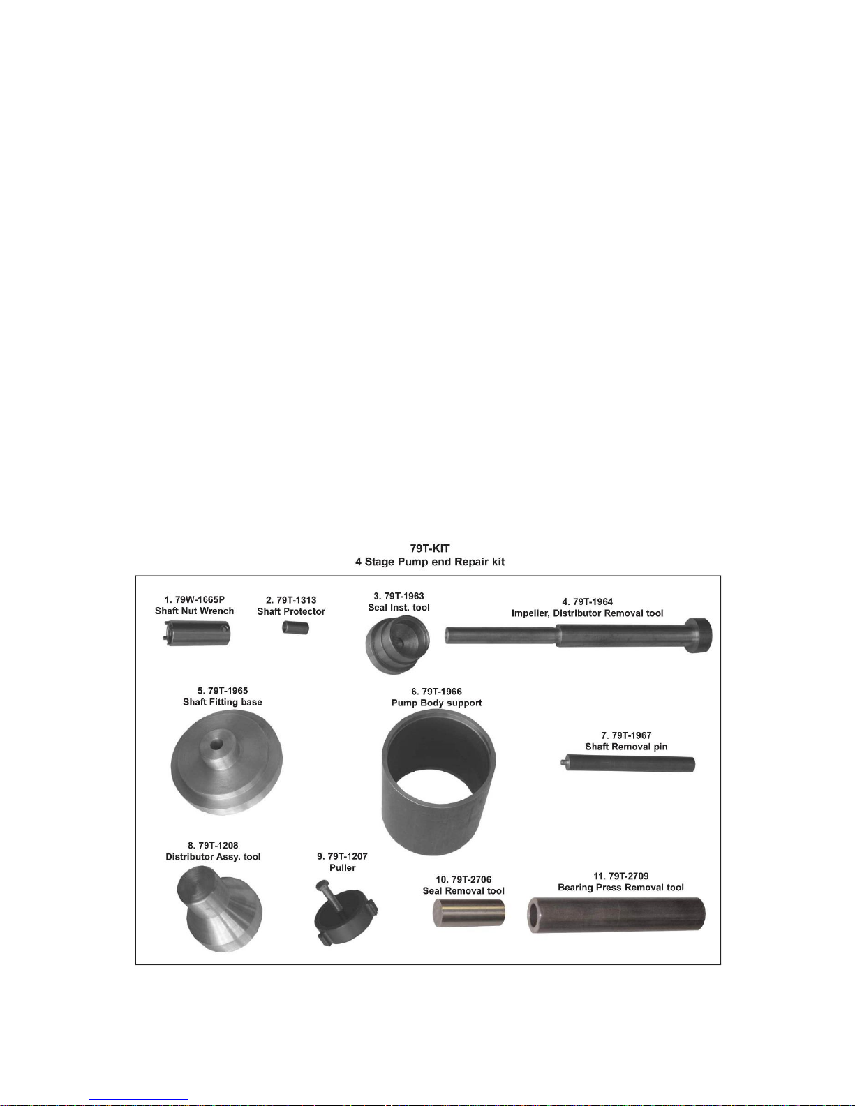
Note 2: Special tools are needed to service the pump. See 79T-KIT illustration below.
5

3.7 PUMP ASSEMBLY
Note: Inspect all components for wear, damage or corrosion. Replace components as required. Always use new "O"
Ring Seals.
1. Place Body (1) on smooth surface or {use Shaft fitting base, 79T-1965) to protect the body from damage, then
press in the Rotary Seal (11) into Body (1).It is important that it be installed correctly, if leakage or damage to
the body is to be avoided {use Seal installation tool, 79T -1963}.
2a. Place Bearing Retainer (8) over Shaft (7) with small shoulder facing up. Support shaft under aluminum collar
between drive pins. Then place Bearing (10) onto shaft pilot and press into place, until it touches aluminum shaft
collar. Press on bearing inner race only {use Bearing press removal tool, 79T-2709}
Note: Pressing on bearing outer race (ring) may damage bearing.
2b. Install Drive Bushing (9) on Shaft (7) and press into place over the flats on the pump Shaft (7). The Drive
Bushing faces should touch the inner race of the bearing.
3. Press in the Shaft Sub-assembly (7), making sure that the drive pins in the Drive Bushing (9) fit into the slots
on the seal to align shaft {use Shaft fitting base, 79T-1965}. Secure with the 6 Bearing Retainer Screws (17).
Note: In some models, lock washers are also used.
4. Place the No.4 Impeller (4) on the Shaft (7), making sure it engages with the Drive Bushing slots (9).
5. Use grease to hold the O Ring (15) in its groove on the Distributor (2) and carefully install over the Impeller.
Ensure it is located in the lowest counter bore of the Body.
6. Place the No. 3 Impeller (4) on the shaft making sure it engages Impeller No 4.
7. Install O rings (16) on Distributors (3) and lubricate with Vaseline.
8. Place distributor on the pump body bore (vanes pointing up) {using Dist. assy. tool, 79T-1208}, and with a
hand press, apply short stokes until the distributor is pressed through the first flat section into the open
waterway. (This can be felt as the distributor free falls onto the next flat.)
The distributor must then be re-centered by hand and repressed as before. This is repeated until the distributor
is in contact with the first distributor already installed.
9. Place the No. 2 Impeller (4) on the shaft making sure it engages Impeller No 3.
10. Repeat operation No. 7 – No. 8.
11. Place the No.1 Impeller (5) on the shaft making sure it engages Impeller No 2.
12. Place Lock Washer (21) over Shaft (7) engaging tab in the milled slot in the shaft thread.
13. Screw Locknut (12) onto Shaft (7) and tighten firmly {use Shaft nut wrench, 79W-1665P} until slot in nut is
aligned with a tab from the Lock washer. Push tab into slot on nut to lock in place.
14. Install O ring (16) on Suction Nozzle (6). Using bench press, press Suction Cover until it rests on Distributor
(3). (.020 to .040” gap between Body (1) and Suction Cover (6) is normal.)
15. Install 8 Lock washers (19) and Screws (14) and tighten evenly, by hand.
16. Attach Shaft Nose (22) to end of Shaft (7) using screw with special plastic locking insert (23).
17. If required, install Priming Adaptor (26). Use Loctite on tapered thread.
18. Install Cap (27) and Gasket (29).
19. Install Plug (28).
Note: Apply Teflon paste or tape on threads before installing plug.
20. Grease the Pump Bearing, using an 11” (280mm) long grease gun. Apply 15 strokes of grease (PT# 79W-
GREASE).
The Pump is now ready for testing.
Note: After testing, the Pump should be re-greased as a small amount of water may have passed through the
seal during the first few seconds of rotation. Apply 2 strokes from the grease gun.
6
 Loading...