


W203 Facelift
Tech 331 203 (FAH,) 7/14/04
1

Model Line Up
W203 launch date – 05/15/04
• New Luxury and Sport line differentiation
• W 203
– C230 1.8K, C240, C240-4, C320, C320-4, C320 Sport
– C55 AMG (normally aspirated) introduction (06/04)
• CL 203
– C230 1.8K, C320
• S 203
– C240, C240-4
– C320 Station Wagon no longer available
2

Features
• Modified headlights, turn signals and tail lights
• Redesigned bumpers and side sills
• Modified radiator grill
– 3 rib design for W/S
– Drilled ribs for CL
• Lower window trim with chrome strip for sport models
• Redesigned instrument cluster
• Redesigned steering wheel (sport models only)
• Revised center console
– Redesigned upper control panel switches (W211)
– Revised HVAC control unit
– Chrome accents
• Standard driver’s lumbar support adjuster
• New Audio head units and modified Telematics
3

• Non AMG
– 16”-18” Wheels for all models
– Softer torque strut bushing on front axle (-22%)
– Softer spring link bushing on rear axle (-60%)
– 1mm thicker torsion bar rear axle (14 mm)
– More direct steering gear (14.5 instead of 15.5)
(also for AMG vehicles)
– Improved, more direct manual gearbox shifter
è Features
Chassis
– Improved agility and handling dynamics
– More precise steering (2.8 vs. 3.3 turns lock to lock)
– Higher level of ride comfort
– Wider stance and sportier look
4

More direct steering ratio
Previously: 15.5
New: 14.5
Modified torque
strut mount
470 N/mm (-22%)
Previously: 600N/mm
Rear spring/damping
Rear torsion bar 1 mm
thicker
Previously W203: 13mm
New W203: 14mm
Spring link mount
11 kN/mm ( - 56%)
Previously: 25kN/mm

Chassis
• 6 Speed Manual gearshift actuation system
– Shift operation performed exclusively by means of a single rod
(previously rod and cable)
– Reverse gear located at front left (previously rear left)
– Reverse gear lockout now performed by pressure point (previously
lift on lever)
– Shift housing decoupled from the bodywork with a large volume
elastomer element
– No shift mechanism adjustments necessary
• 6-Speed manual Gearbox (716.6)
– Gear selection mechanism adapted
– First Gear Synchronization modified
– Reverse gear assembly adapted to new shifter position
6

Manual Transmission
Only available on Sport coupes and sedans
– Sport è 20 mm shorter lever
è 20% shorter shifter travel
7

Technical Description
Gears are shifted and selected via a
central shift rod without any losses due
to redirecting motion
Comfort element directly below the
shift lever handle to facilitate
harmonious shifting, at the same
time neutralizing engine and
transmission excitations
Decoupling to the chassis by a
large-displacement elastomer
element integrated in the casing
8

Steering Wheel Gearshift Buttons
• Steering wheel gearshift buttons (option code 428)
– Gearshift buttons placed on back of steering wheel
(like AMG)
– Both gearshift buttons have ‘+’ & ‘ -’ functions
(double throw button)
– Gearshift buttons connected to Steering Control Module (SCM) via
LIN-bus
– Gearshift buttons are active
in all transmission modes (S,C,M)
– Manual mode features
• Up shift at rpm limit
• Downshift when rpm critical
• 1stgear selected at standstill
• S mode selected after ignition
cycle
9

Steering Wheel Gearshift
• Steering wheel gearshift button data flow
LIN Bus
Voltage coded
q Steering wheel
shift request
CL203
AMG
Legend
N80 Steering control module (CAN -B connection)
S110/1 Steering wheel shifter left (Minus–AMG)
S111/1 Steering wheel shifter right (Plus- AMG)
1 LIN-Converter
(in steering wheel)
W203
10

C 55 AMG
• AMG 5.5 liter naturally aspirated V8
• 362 hp @ 5750 rpm
• 376 lb-ft (510 Nm) torque @ 4000rpm
• 0-60 mph ~ 5.1 seconds
• Unique front end module (CLK design)
• 80 mm longer (roomier engine bay)
• Wider track
• 3 slat grill and MB Star on hood
C 32 AMG vs. C 55 AMG
11

C 55 AMG
• AMG body styling with spoiler lip on
trunk
• AMG brake system (as C32 AMG)
• AMG sport suspension
• AMG SPEEDSHIFT 5 speed
automatic
with steering wheel shift buttons
– No up shift at rpm limit
12
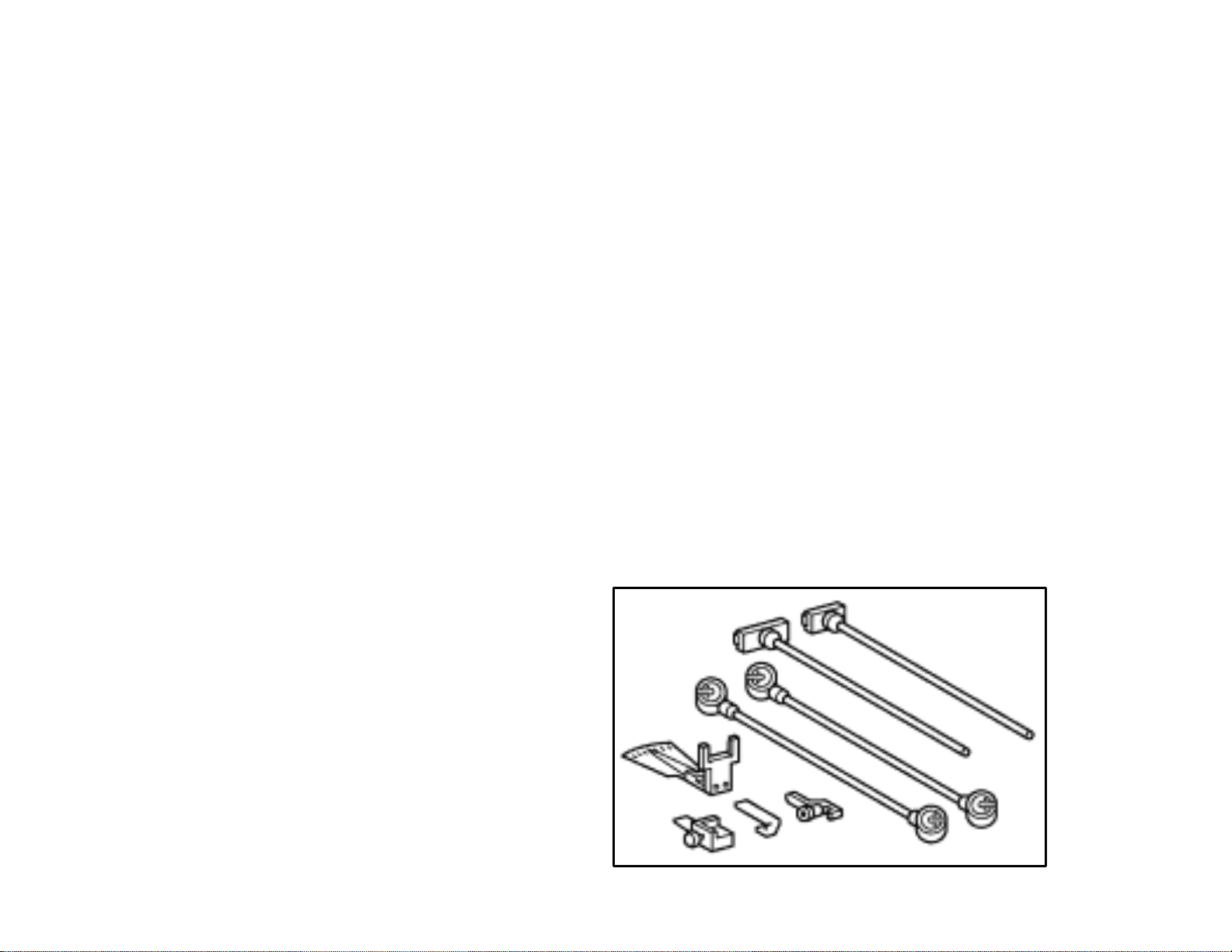
Windshield Wiper Arm Adjustment
• Aero wiper blades equipped on all lines
• Windshield Wiper Arm Adjustment Kit
– Countermeasure for wiper noises (shudder/squeak)
– Measure and adjust wiper blade angle to windshield
• Angle of attack at park position
• Angle of attack at direction change
– Applicable for 203, 209, 211, 215, 220, 230
– Service Tool Kit number 211 589 02 21 00 (B-Tool)
• Order put in to Germany, no ETA to USA
– Content
• Angle Measure
• Wiper arm adapter
fittings
• Wiper arm adjustment
levers
13

Windshield Wiper Arm Adjustment
14

Electrical System
15

Fuse Concept
F32 Front Pre-fuse box
F34 Interior Fuse box
N10/1 SAM-Driver
N10/2 SAM-Rear
Fuses 1-20 à N10/2
Fuses 21-42 à F34
Fuses 43-65 à N10/1
16

Fuse Concept
F32 Front Pre-fuse box
F34 Interior Fuse box
G1 Alternator
M1 Starter
N10/1 SAM-Driver
N10/2 SAM-Rear
N14/2 Not used (CDI)
W10 Ground
(engine compartment)
* Not Used (CDI)
** Alternator cable fuse
M271 only à 175A
17

Networking Map - Vehicle
CAN C
N93*
CAN B
X63/4
X30/6
N15/5N15/3N47/5N3/10
N123/4
A1N73N80
N22 N70
N72/1
N69/2
N72
N69/1 N69/3
CAN D
N93
N69/4
X11/4
B48/5
X30/7
X35/41N32/2N32/1N10/2N2/7A2N10/1
N62
* N93 only installed until ~12/04, EIS takes over functionality
X35/3
X55/4
18

Networking Map - Legend
CAN B
A1 - Instrument cluster (IC)
A2 - Radio
B48/5 - Passive Occupant Detection System
N2/7 - Supplemental restraint system (SRS)
N10/1 - Driver SAM
N10/2 - Rear SAM 1
N22 - Automatic air conditioning (AAC)
N32/1 - LF Electric seat adjustment (ESA)
N32/2 - RF Electric seat adjustment (ESA)
N62 - Parktronic (PTS)
N69/1 - LF Door control module (DCM)
N69/2 - RF Door control module (DCM)
N69/3 - LR Door control module (DCM)
N69/4 - RR Door control module (DCM)
N70 - Front overhead control module (OCP)
N72 - Lower control panel (LCP)
N72/1 - Upper control panel (UCP)
N73 - Electronic ignition switch (EIS)
N80 - Steering column module (SCM)
N93 - Central gateway (CGW)
X30/6 - CAN B network connector
X30/7 - CAN B network connector
N80 - Steering column module (SCM)
N93 - Central gateway (CGW)
X63/4 - CAN C network connector
CAN D
N93 - Central gateway (CGW)
N123/4 - TELEAID
X11/4 - Diagnostic connector
Legend Key
Indicates discreet
wire to diagnostic
connector X11/4
CAN B & CAN C
control module
CAN C
A1 - Instrument cluster (IC)
N3/10 - Motor electronics (ME)
N15/3 - Electronic transmission control (ETC)
N15/5 - Electronic shifter module (ESM)
N47/5 - Electronic stability program (ESP)
N73 - Electronic ignition switch (EIS)
CAN B
control module
CAN C
control module
19

Networking Map – CAN B
N73 N70 N22 A1 N72/1 N10/1
N80
X30/6
X30/7
N93*
N10/2 N32/1 N69/1 N69/2
A2
CAN H (BN/RD) except N10/2 (BN/GY) / CAN L (BN)
* N93 only installed until ~12/04, EIS takes over functionality
N69/4 N2/7
B48/5N69/3N32/2
20

Networking
List of new ECU’s or those that have been modified:
• Central Gateway
• Electronic Ignition Switch
• Instrument Cluster
• Electronic Stability System
• Climate Control
• Electronic Selector Module
• Steering Control Module
• Upper control panel
• Supplemental Restraint
System
• Weight Sensing System
• Audio 20
• MCS II
• Satellite Radio Receiver
• CD Changer
• Voice Control
• CTEL Handy Interface
• Sound Amplifier
• Dual System TELE AID
21

Networking
• Central Gateway (CGW) Tasks
– Primary gateway between CAN B and CAN C
– Gateway between CAN B and CAN D
• Only if version coding set to TELE AID present
– Diagnostics gateway between CAN D and CAN B/C
– NO System Diagnosis
– Installed until approximately 12/04
à Removed in connection with modification year AJ04/2
• Electronic Ignition Switch (EIS) Tasks
– Limited gateway between CAN B and CAN C
– Master Version Coding
– DAS III functionality
– Functionality of Central Gateway as of approximately 12/04
22

Instrument Cluster (IC)
• 4 Tube design (with chrome rings)
•Engine Temperature gauge is back
• Vertical Multifunction display
•Central display (operated via MF-steering wheel buttons)
•Lower display (Basic information)
Headlights On Indicator
Tire Pressure Monitor Indicator
23

Instrument Cluster (IC)
• 3 Versions of cluster used depending on model
– Luxury
– Sport (Deeper, angled chrome rings)
– AMG (Aluminum detailing and 200mph speedometer)
• Maintenance calculator
– MB Maintenance System replaces FSS
• Maintenance Booklet
– Fixed maintenance intervals with automatic reminder
• 10000 miles or one year for AMG and V12 models
• 13000 miles or one year for all other models
– MB Service Welcome replaces Maintenance Commitment
• First Shop Visit (1 hour)
• First Tire Rotation
– Synthetic oil according to sheet 229.5 is required
• Mobil 1 0W -40 is recommended by MBUSA
24

Electronic Stability System (ESP)
• Private-Bus (CAN)
– CAN between ESP and micromechanical turn rate sensor
(B25/15)
– 2-wire CAN used to transmit rotational speed and lateral
acceleration data to ESP
• Brake light control
– Brake switch eliminated
– Release contact of BAS system used to determine brake
application
(brake pressure & membrane travel used as back up)
– Redundant signals
• Discrete wired from ESPàSAM-D (looped)àSAM-R
• CAN signal ESPàEISàSAM-R
• SAM-R confirmation reply via CAN
– Brake light suppression via CAN message from ESP
25

Climate Control - Thermatic
Dual-zone climate control
• Automatic control of temperature, air flaps & blower speed
• Independent left / right temperature selection
• Joint left / right air distribution
• Blower speed ‘0’ to turn system off
• Interior temperature measured at control panel only!
• Dew point sensor
26

Climate Control - Thermotronic
• Automatic control of temperature, air flaps & blower speed
• Independent left / right temperature selection & air distribution
• Active Charcoal Filter
• Residual Engine Heat Utilization (REST)
• Key dependant memory settings
• ‘Off’ button to turn system off
• Interior temperature measured at control panel only!
• Solar sensor and Multifunction sensor
27

Steering Control Module (SCM)
• 2 basic versions
– W/S 203 (standard) à Multifunction steering wheel buttons via
voltage coding
– CL203 or Steering wheel shift buttons (option) à Multifunction
steering wheel buttons via LIN-Bus
• Rear wiper functions (S203)
– Multifunction switch with controls for rear wiper
Note: The front windshield wiper motor is now controlled via
serial data bus (LIN-BUS) from SAM-Driver
28

Upper Control Panel (UCP)
• New design with Push/Push-buttons
• Seat Heating control modifications
– 3 Stages (5, 10, 20 minutes)
– No heating if interior temperature >40°C (104°F)
– 5 minute memory after ignition off
Legend
N72/1 Upper Control Panel
N72/1e1 Airbag OFF light
N72/1s1 ESP OFF switch
N72/1s4 Rear head restraints switch
N72/1s5 Hazard warning system switch
Note: Optional equipment shown
N72/1s26 Interior central locking (Lock)
N72/1s16 Interior central locking (Unlock)
N72/1s27 TS switch with ATA
N72/1s19 IR switch with ATA (not USA)
N72/1s8 PTS OFF switch
N72/1s9 Rear blind switch
N72/1s10 Left front HS switch
N72/1s11 Right front HS switch
29

Outside Lighting
• Reflection technology with clear lens and H7 main beam
• Projection technology with clear lens and Bi-xenon (SA)
• Bi-xenon package includes cornering fog lamp function
(not for sport models or AMG)
• Mirror turn signals with clear lens
• Tail lights / 3rdbrake light in high brilliant optic
30

Outside Lighting – Cornering Fog Lamp
• Cornering Fog Lamp is an additional light function realized with
special fog lights (61° versus 21° reflector, H7 55 Watt bulb)
• Fog light on the inside of the turn is activated under specific steering
angle or turn signal requests
• Inverse activation if reverse gear is engaged
• Fog light is activated dependant on
– Turn signal activation
– Steering wheel angle
– Vehicle Speed
– Reverse gear
• Soft dim activation and deactivation
• All functions related to this feature are controlled by SAM-Driver
à Not a version coding, unique SAM-Driver
31

Outside Lighting – Cornering Fog Lamp
RemarksPulse modulatedSubstitution lightBurned Bulb
Only with parking lightYesRear fog light leftParking light rear left
(outside)
Only with parking lightYesRear fog light rightParking light rear right
(outside)
NoRear fog light leftBrake light left
NoRear fog light rightBrake light right
Brake light right is also
shut off & Rear fog light
right activated
Brake light left is also
shut off & Rear fog light
left activated
Only with parking light100Hz/25%Fog light frontParking light front left
Only with parking light100Hz/25%NS rightParking light front right
Hella H7 bulb
32

Outside Lighting - Cornering Fog Lamp
33

Outside Lighting - Cornering Fog Lamp
Road illumination
without cornering
fog lamp function
Note: Do not confuse with dynamic headlamps from W211
Road illumination
with cornering
fog lamp function
34

Outside Lighting - Cornering Fog Lamp
• Cornering fog lamp function pre-requisites
– Engine running (circuit 61 on, or engine >300rpm)
– Light switch in position “Auto” / “On” or Daytime Running Lights
active
– “Light On” from Rain/Light sensor (darkness for “Auto”)
– Vehicle speed < 25mph
– Cornering light request over turn signal (priority) and/or steering
angle
– Activation of fog light in turn signal / steering direction
• Cornering fog lamp function with Reverse (same as above except)
– Reverse gear engaged (>0,5 sec.)
– Cornering light activated by steering angle only
– Inverse activation of fog light to steering direction
35

Outside Lighting - Cornering Fog Lamp
• Only one cornering fog lamp is activated at a time
– Both may be on at the same time due to activation curve
– Dim on and dim off times vary (off is longer)
On criteria met
Max bright
reached
Off criteria met
Legend
t Time in ms t
tRReaction time (<100ms) t
t
On time (dim-on) t
EIN
t
Off time (dim-off) U
AUS
nachlauf
mindest
Activation time (based on activation criteria) U
X
Run-on time (0-5s) U
Minimum activation time (0-5s) U
eff
eff max
eff Sprung1
eff Sprung2
Effective Voltage
Maximum U
30% U
Shut down U
(dim -on)
eff
eff
eff
(dim -off)
36

Outside Lighting - Cornering Fog Lamp
• Immediate deactivation of cornering fog lamp without dimming if;
– High Beam activated
– Fog lights activated
– Diagnostics
– Hazard Flasher activated
– Light switch turned to position 0
• Fault handling
– Fault affecting only cornering fog lamp
• IC message regarding unavailability of cornering light
– Fault affecting fog light
• IC message regarding corresponding fog light failure
(Cornering light also unavailable but no message)
37

Outside Lighting - Cornering Fog Lamp
Light switch in Auto
- input to SAM -D
j Light On from Rain/Light sensor m Speed signal p Cornering
light On
k Turn signal active n Circuit 61, engine running
l Steering angle signal o Engine RPM
Legend
A1 Instrument Cluster G2 Alternator N73 Electronic Ignition Switch
E5/1 Fog Light; left N10/1 SAM-Driver N80 Steering Control Module
E5/2 Fog light; right N3/10 Engine Management
38

Supplemental Restraint System
(SRS)
39

Supplemental Restraint System
(SRS)
• SRS system with maximum of 14 ignition squibs
• New features
– Upfront sensors (B48/1 & B48/2)
à USA only
– Passenger Airbag with dual inflation system
– Occupant classification system
– Deletion of passenger seat occupancy mat (B48)
40

Occupant Classification System
• FMVSS 208 requires the progressive implementation of
advanced airbags on all production vehicles by MY 2007
• Advanced air bags systems determine the proper airbag
deployment and power levels based on any of the following:
– Occupant size / weight
– Seat belt use
– Crash Severity
• To fulfill this requirement a new occupant classification system
was developed
– Passive-Occupant-Detection-System-B (B48/5)
– SRS system adaptation (AB)
41

Occupant Classification System
• Implementation schedule
– CL 203 à Start of production (04/04)
– W/S203 à Delayed introduction approx. 07/04, but C55 AMG
will never get this system
• System design
– A silicone oil filled mat placed underneath the foam cushion
measures pressure (weight) put on the seat
– System activates to determine whether to deploy airbag and
tailors the inflation of the front passenger’s front air bag to the
occupant classification of the seated occupant
• System components (on top of SRS module)
– Bladder mat & Pressure sensor
– Belt tension sensor
– OCS control module
42

OCS Vehicle Identification
• Vehicles equipped with Advanced Air Bags need to display this
accordingly
Labels affixed to back
of sun visors
Additional label affixed to ash tray cover
(Temporary label, removed after delivery)
43

OCS – Customer Indication
• Primary Airbag state indicator is Passenger Airbag Off light
(new icon for all OCS systems as of MY05)
Location: Upper control panel (center console)
– Lit upon Ignition On (6 seconds)
– Lit until system recognizes
an occupant needing Airbag enabled
– Not lit if adult person recognized
à Airbag may still not deploy in an accident if not required
• Proper seating position (backrest) is critical for proper classification
• Passenger Airbag Off light indicates all deactivated conditions, not just
BabySmart child seats
à Light is always illuminated if no passenger seated
44

OCS – Customer Indication
• Additional reference messages displayed in instrument cluster
– Displayed only if implausible weight class change occurred that
results in an Airbag state change
• Passenger door not open
• Weight classification change without running
through class 0
– Not all Airbag state changes will trigger an instrument cluster
display message
Airbag On à Off
Airbag Off à On
45

Malfunction Indication
Note: Not a W203 C-Class instrument cluster (picture representative)
No specific message related to OCS, only SRS malfunction
Indicator for a OCS problem is additional Airbag Off light ON
despite an adult sitting in the passenger seat
46

OCS – Control Module (N2/13)
• Tasks
– Supply power (5V) to belt tension sensor (B48/3) and pressure
sensor (B48/4)
– Interpret data from pressure sensor (B48/4) attached to silicon
bladder and belt tension sensor (B48/3) attached to end of seat
belt
– Calculate weight classification of occupant on seat
– Provide weight classification and seat occupancy data on CAN B
– Self-test of ECU and sensors (upon power up) and log fault
codes
Location:
Under passenger
seat
(attached to frame)
47

OCS – Pressure Sensors (B48/4)
• Pressure sensor (B48/4)
– Measures pressure inside silicon filled bladder mat
à permanently attached to bladder mat
– Bladder mat geometry is adapted to each seat / vehicle à same
pressure measurement independent of the
pressure point area
– Permanently assigned to OCS controller due to adaptation
process at manufacturer
à tamper indicator connector
(seal discolors from pink
to purple if unplugged)
48

OCS – Belt Tension Sensor (B48/3)
• Belt tension sensor (B48/3)
– Measures tension (pull) on the seat belt at the anchor point
à permanently attached to seat belt
– Value used to determine correction factor of bladder pressure
sensor
à Seat belt anchor point is below weight measuring area
and can therefore influence reading
Location (CL shown):
W/S203 Belt anchor point at seat frame
CL203 Belt anchor point at B-pillar
49

OCS – Weight Classification
• OCS Process
– Ignition 15R initiates self-test
– Pressure present in bladder mat is measured
– Weight adjustment factor is calculated from seat belt
tension
– Weight classification is determined
– OCS sends CAN B messages
• Passenger seat occupancy state
• Passenger weight classification (0-4)
– AB sets airbag deployment state
• Enabled / Not enabled
• Deployment level (1st/ 2ndstage) based on weight class
and accident severity
– AB sends CAN message to Upper Control Panel to activate
/ deactivate Airbag Off light
50

OCS - Diagnosis and Repair
• All diagnostic procedures are in SDS/DAS 04/04
• Proper seat backrest position is vital for accurate classification
• Special Tool required for calibrating system
– Set of weights to verify accurate weight classification
• System requires calibration after OCS component replacement
51

OCS - Diagnosis and Repair
• Belt tension sensor replaced together with seat belt
à “Zero” sensor in OCS controller after installation
• Bladder mat and OCS controller only replaceable as a unit togeth er
with:
– Cushion frame
– Cushion
– Cushion cover
• Service Kit contains all of the above
• Pressure sensor should never be unplugged from control unit
à swapping for test purposes has no use since bladder
and controller are matched for tolerances
à discolored connector seal indicates tampering
52

Audio COMAND (MCS2)
Overview:
• Oneblock device
• FM /AM tuner inclusive weatherband
• Extra CD drive for audio
• Gateway CAN-B --> MOST
• AUX input
• 4 channel amplifier
• Services: roadside assistance, MB
info, E call
Supported MOST components :
• CD changer
• Universal portable C Tel interface
(UPCI)
• Voice control system module
• Audio amplifier
• SDARS
Πslot in for navigation
• slot in for audio CD
53

Most Ring Illustration
• A40/3 – COMAND
• A2/13 – Sound amplifier
• A35/11 –Voice control
• N123/1 – Universal portable CTEL interface
• N87/5 – Satellite module
• A2/6 – CD changer
54

COMAND Networking
• A1 – Instrument cluster
• A40/3 – COMAND
• A2/13 - Amplifier
A2/6
• A35/11 –Voice control
• N123/1 – Universal portable CTEL interface
• N87/5 – Satellite Module
• A2/6 – CD changer
A2/13
• N80 –Steering column module
• S110,112 – Left, right
multifunction
steering wheel
button group
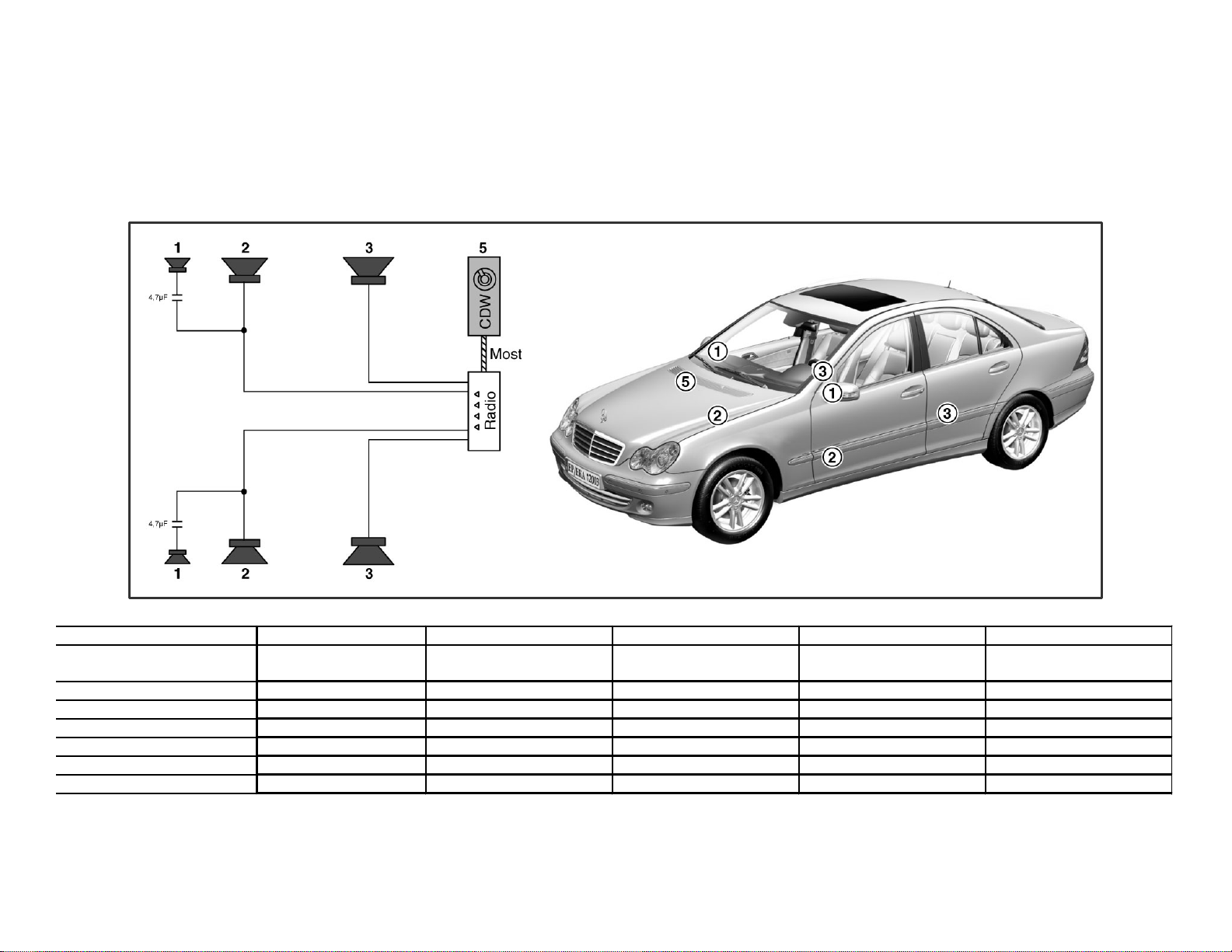
55

Location of Components
A2/13
• B25/6 – Sound amplifier microphone
• A28/3 – E Network compensator
• A2/22 – Telephone antenna
• A2/72,73 –Window antenna
amplifier 1 and 3
• H4/57 – Rear speaker
• H4/29 – Rear speaker
• H4/54 - Rear speaker
• H4/1-4 – Door speakers
• S93/2 – VCS switch
• S110,111 – Left, Right multifunction
steering wheel button group
56

A2/13
57

COMAND 203
The plug assignment is as follows
1 loudspeaker and power supply and
MOST
RF Radio antenna plug
ZF Intermediate frequency plug
GPS GPS antenna plug
58

Camber 1 & 2 16-Pin codeage A
PIN Signal/Signalinfo
•
Stecker 1
1 HR + (loudspeaker)
2 VR + (loudspeaker)
3 VL + (loudspeaker)
4 HL + (loudspeaker)
5 HR - (loudspeaker)
6 VR - (loudspeaker)
7 VL - ( loudspeaker)
8 HL - ( loudspeaker)
•
Stecker 2
9 CAN-Low
10 phone Mute
11 CAN-High
12 tm. 31
COMAND 203
13 antenna
14 free
15 tm. 30
16 Wake-Up
Camber 3, connector 3 (12-PIN, codeage B)
PIN Signal/Signalinfo
1 FAN – (external fan)
2 Free
3 Free
4 Free
5 AUX-Shield
6 AUX Left Channel (glove ox)
7 FAN + (external fan)
8 DIAG fan (diagnose external fan)
9 Free
10 Free
11 AUX-GND (glove box)
12 AUX Right Channel (glove box)
Camber 4, connector 4 (12-PIN, codeage A)
PIN Signal/Signalinfo
1 Free
2 Free
3 Reserved
4 Free
5 Shield (rear audio entertainment)
6 Left channel (rear audio entertainment)
7 Free
8 Free
9 Reserved
10 Reserved
11 Ground (rear audio entertainment)
12 Right channel (rear audio entertainment)
59
Loudspeakers Without Option SOUND
part-Nr.: A 203 820 01 02 A 203 820 11 02 A 203 820 15 02 A 203 820 08 02 A 203 820 90 89
designation: loudspeaker
hightone
producer: Harman Harman Harman Harman Alpine
measures: [mm/l] Ø 36 Ø 168 Ø 155 Ø 230 181, 250, 71
Magnet/weight: [kg] 0,06 0,5 0,410 0,9 1,8
Output Sinus: [Watt] 18 18 18 18/18 -
Transfer frequency: [Hz] 5k – 20k 55k – 7k 120k – 10k 40k – 130k -
Impedance: [Ohm] 4 4 4 4/4 -
loudspeaker
middletone
loudspeaker
widetone
loudspeaker
deeptone
CD-changer
60

Loudspeakers with SOUND
location: 1 2 3 4 5 6 7 8 9
Part-Nr.:
Designation:
Producer: Peiker Harman Harman Harman Harman Harman Harman Alpine Harman
Measures:
[mm/l]
Magnet / weight
[kg]
Output Sinus:
[Watt]
Transfer
frequency: [Hz]
Impedance:
[Ohm]
A203 820 15 35 A 203 820 43 02 A 203 820 50 02 A 203 820 51 02 A 203 820 52 02 A 203 820 53 02 A 203 820 54 02 A 220 827 46 42 A 169 820 13 89
ZB Microfone
Soundsystem
Ø 8,08 Ø 80
0,003 0,140 0,055 0,900 0,960 2,500 0,175 1,800 1,300
- 40W 40W 40W 40W 40W 40W
- 150HZ-20KHZ 1KHZ-20KHZ 20HZ-20KHZ 20HZ-20KHZ 20HZ-150HZ 150HZ-20KHZ -
2,2 ohms 2 ohms 2 ohms 2 ohms 2 ohms 2 ohms 2 ohms -
ZB LS
Centerfill
ZB LS
Hightone
ZB LS
TÜR Vorne
ZB LS
Tür Hinten
ZB LS basebox
Deeptone+
Surround .
ZB LS
Surround Re
CD-changer
Amplifier
61

Mercedes-Benz USA
W203
W203 MOPF (PlateO) 5-4-04
Questions ?
62
 Loading...