


r
Transporters • Electrical System
VITO/VIANO (Model 639)
Wiring Diagrams
a
mb
Technical training for Customers
As at 06/05

Wiring Diagram Manuals Part Number: Z6517 2111 02
This document is intended solely for use in training and is not subject to regular updating. Part numbers and
documentation included in this document may change and the latest information should always be used.
Printed in England
Æ 2005 Copyright DaimlerChrysler UK LTD
Publisher: Mercedes-Benz CV Electrics & Telematics Team
This document with all its sections is protected under the laws of copyright. Its use for any purpose whatsoever
requires the prior written consent of DaimlerChrysler UK LTD. This applies in particular to its reproduction,
distribution, modification, translation, recording on microfilm or storage and/or processing in electronic systems,
including databases and on-line services.
Note:
The term »employees« does not imply any
preference of gender and incorporated male and
refers to male and female employees alike.
Contents
Chapter Title
1 Use of wiring diagrams
2 Abbreviations for wiring diagrams
3 Location and assignment of ground points
4 Location and assignment of plug connectors
5 Battery starting charging circuit
6 Voltage supply fuses
7 Fuse and relay board (SRB)
8 Signal Acquisition and actuation module (SAM)
9 Exterior lights
10 Central locking
11 CAN bus
12 Instrument cluster (IC)
13 Electronic ignition switch (EIS)
14 Electronic stability control (ESP)
15 Common rail diesel injection (CDI)
16 Standard heater
06/05 Transporters • Electrics <>Van - Electrical Systems
Wiring Diagrams VITO (Model 639)
Use of Wiring Diagrams Chapter 1
06/05 Transporters • Electrics <>Van - Electrical Systems
Wiring Diagrams VITO (Model 639)
OV00.01-S-1901-03VA Use of wiring diagrams
Wiring diagrams
The wiring diagrams are assigned to the familiar function groupsa
00-91. The systems are listed alphabetically with an indication of
the function group/ function subgroup in the "Search aid for all
wiring diagram groups"
OV00.01-S-1901VA or A3 (paper version).
The wiring diagrams are filed in the respective function groupa
arranged according to the PE number,
e.g.: PE07.16-S-2000VA
PE07.16-S-2000IVB
To check the completeness of the volume the sequence of the
wiring diagrams filed can be seen from the lists of contents of the
respective function group. For supplements the wiring diagrams
should be filed as per the supplement sheet.
e.g.: PE00.19-P-1100VA Overview of wiring diagrams....
-----------------------------------------------------------------------------------
Noteson the accompanying documents for connectors/ terminala
blocks (B1)
Special equipment (SA) is specifically highlighted in the notes
column. For connectors, which are installed in special
equipment, the special equipment is specified in the notes
column in the row in front of the connector designation. For
connectors, which are installed as standard, special
equipment specification is noted directly at the respective jack
and/or connector.
The wiring diagramsare prepared as function diagrams or controla
unit diagrams and are built up as follows:
-Function diagrams
The control units and electrical components belonging to the
function are shown as symbols. The functional connections are
realized by direct lines or by the data bus.
-Control unit diagrams
Control units are represented complete with all connected
components. The feed of the control units appears first.
The wiring diagrams also contain linkages of possible versions and
functions.
Linkages, recognizable as versions, are framed and provided with
an abbreviated designation/ abbreviation.
The versions are designated with 1
and 2
-------------------------------------------------------------------------------------
The feed of the terminal blocks is shown by means of an
arrow pointing to the left, the outputs by means of arrows
pointing to the right. The grouping of the individual variants/
special equipment (SA) is highlighted by means of broken
lines. All outputs to components, which are installed as
standard, are listed up to the first broken line.
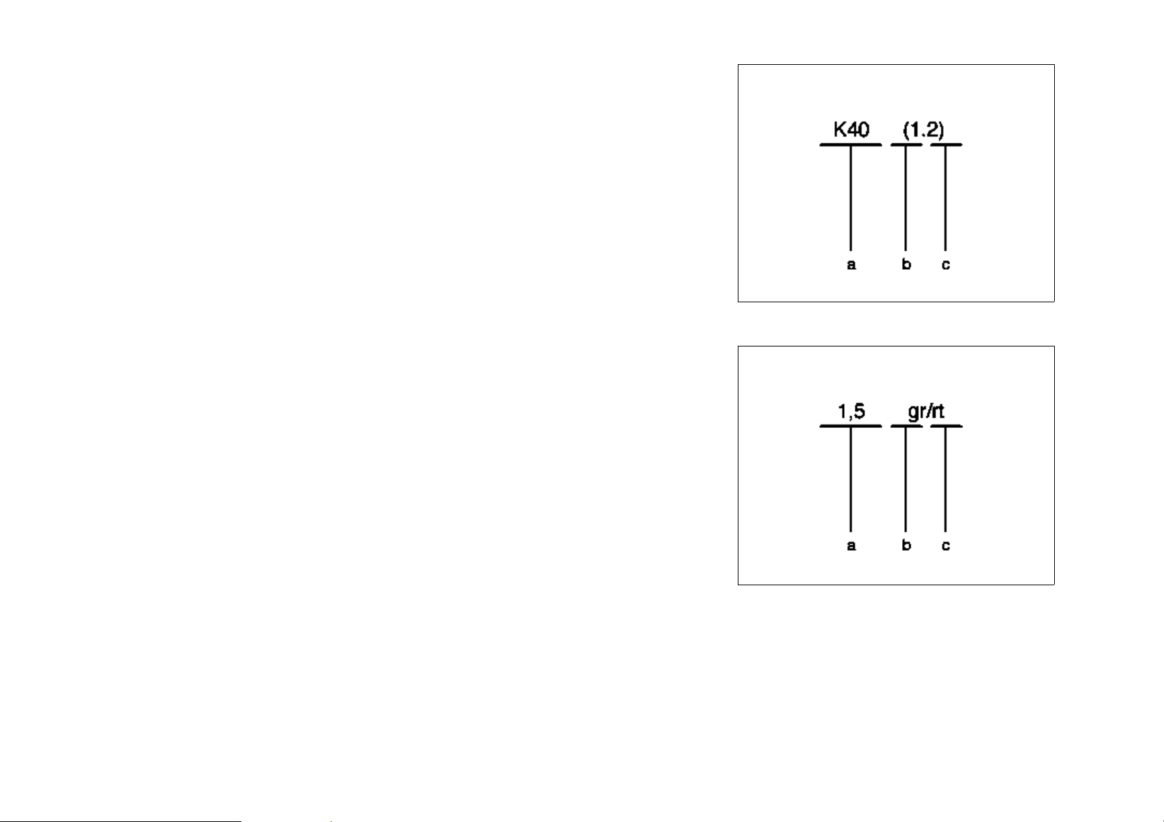
Connection designation
a Component
b Clutch
c Socket
Wire designation
a Conductor cross-section in mm
b Basic color
c Identification color
P00.19-0402-01
2
P00.19-0403-01
 Loading...