

Mercedes-Benz Unimog 435, Unimog 435.111, Unimog 435.110, Unimog 435.117, Unimog 435.160 Service Manual
...
Mercedes-
Benz
Unimog
Workshop Manual
Unimog
435
Volume 1
Service
© Buch&Bild, Helma Wessel
Buch&Bild hat 1994 vom Produktbereich Unimog der damaligen Daimler-Benz
AG
das Exklusivrecht
fUr
den Nachdruck der technischen Unimog- und MBtrac-Oldtimer-Literatur erhalten.
Silmtliche
Rechte der Verbreitung - in jeglicher Form und Technik
einschlieBlich der Einspeicherung
in
elektronische Medien - sind vorbehalten.
Technical details of the vehicle
in
relation to data and illustrations contained
in
this manual
are subject
to
change.
All
rights, including reprint, reproduction
or translation
(also of extracts), reserved.
Nachdruck
2008
Printed
in
Germany
Buch&Bild
Helma Wessel
Finkenweg 13
D 76571 Gaggenau
TeL
+49
(0)
7225/4347
Fax
+49
(0)
7225/4779
wessel@buchundbild.de
www.buchundbild.de
Stand 5.1989
UKD 30 402
21
42
03
The
present
Workshop
Manual
contains
the
descrip-
tions
of
all
important
assembly,
adjusting, testing
and
repair
work.
The
entire contents of
the
Workshop
Manual
are
subdi-
vided
according
to
the
well-known
group
system.
The
group
index
serves
to
facilitate
finding
the
individual
groups,
the
list
of
contents of
each
group
serves
to
find
the
individual
jobs
to
be
carried
out.
The
relevant
data,
settings,
dimensions
and
toleran-
ces
as
well
as
the
special
tools
are
compiled
on
the
first
pages
of
the
respective
groups.
Introduction
The
contents
are
listed
according
to
unit
versions
and
further
subdivided
into
chapters
and
sections.
The
contents
are
subdivided
to
provide smaller, integrated
sections.
Each
section
begins
with a new
page
1
an~
is
identified
as
follows
(example):
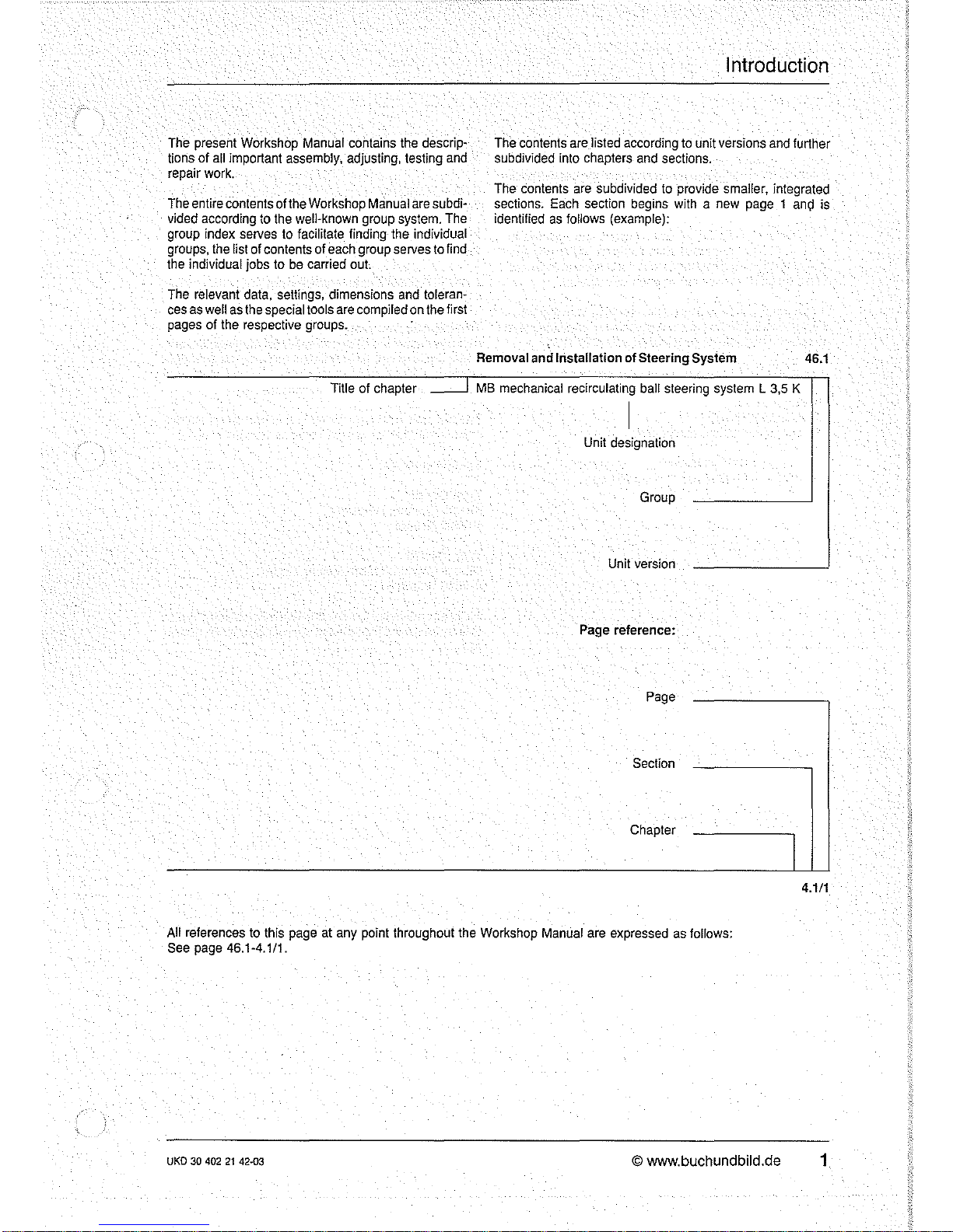
Removat and Installation of Steering System
46.1
Title of chapter
~
MS
mechanical
recirculating
ball
steering
system L 3,5
K
I
Unit
designation
Group
Unit
version
Page
reference:
Page
Section
Chapter
I
4.1/1
All
references
to
this
page
at
any
point throughout
the
Workshop
Manual
are
expressed
as
follows:
See
page
46.1-4.1/1.
UKD
30
402
21
42·03
© www.buchundbild.de
1
Introduction
The
unit
versions
are consecutively numbered starting
with 1; i.e. each version has a special code number. In
addition, the unit designation
is
shown at the head of each
page.
A separating sheet and a detailed list of contents
head each unit.
The sections valid for
all unit versions are covered in
version
O.
The respective data (settings, tightening tor-
ques, machining dimensions etc.) and special
tools are
listed together
at
the start of each unit version.
The numerical values
in
SI
units resulting from the introduction of the international unit system are converted and
rounded-off values (in accordance with
DIN 1335).
The pressure values specified
in
bar are positive.
Pressure In
bar
Previous Unil kp/cm
2
(Kilo ponds per square centimeter)
1 bar = 1.019716 kp/cm
2
- 1.02 kp/cm
2
1 kp/cm
2
= 0.980665 bar - 0.981 bar
2
Power
in
kW (kilowatt)
Previous unit HP (horsepower)
1
kW=
1.360 HP
1 HP = 0.735 kW
Torque
in
Nm
(Newtonmeters)
Previous unit kpm (kilo pond meters)
1 Nm = 0.101972 kpm - 0.102 kpm
1 kpm = 9.80665 Nm -
9.81
Nm
The specified part numbers and the figure numbers in the
exploded views are designed
solely for identHication purposes and improve differentiation between the individual
versions. When ordering spare parts, always use the part
numbers
given
in
the
valid
microfiches.
The job descriptions provided
in
this Workshop Manual
make allowance for special versions (see
00 - 1.6/1).
Special vehicles:
Type
Condor
Messrs Thyssen Henschel
0-3500 Kassel
Type
TN 170
Messrs Thyssen Maschinenbau GmbH
0-5810
Wilten
6
We
shall endeavour to keep this Workshop Manual up-todate by supplying the relevant"Supplementswhen necessary.
Contents
Chapter
1 General
Installation
survey
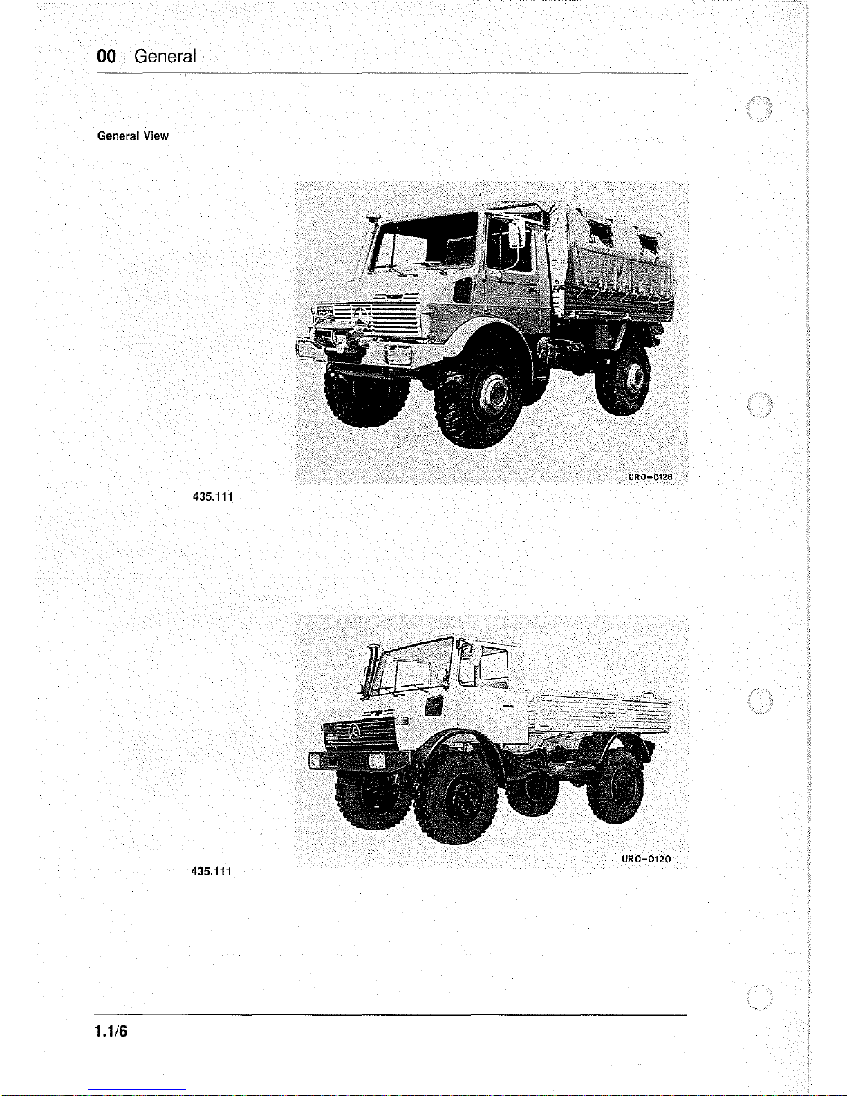
General
view
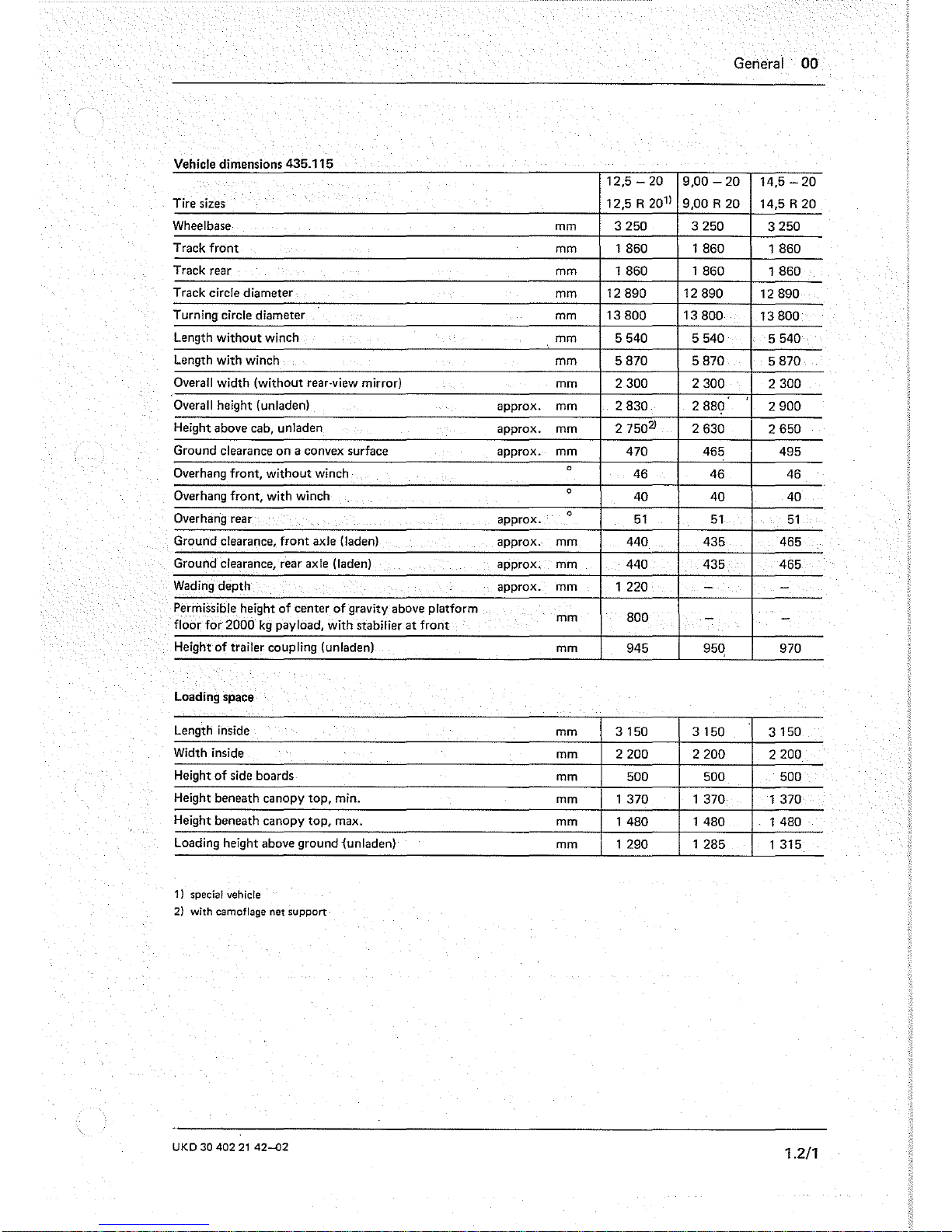
Vehicle
dimensions
435.115
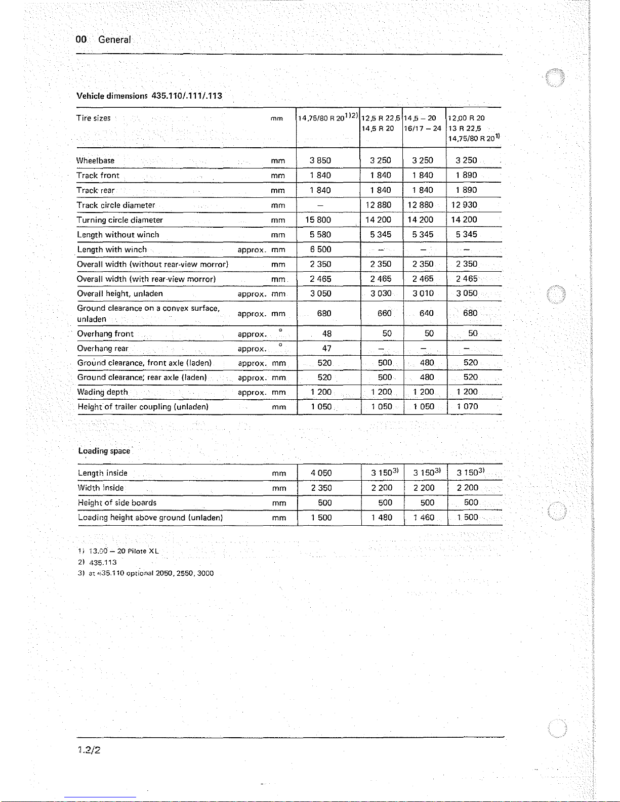
Vehicle
dimensions
435.111
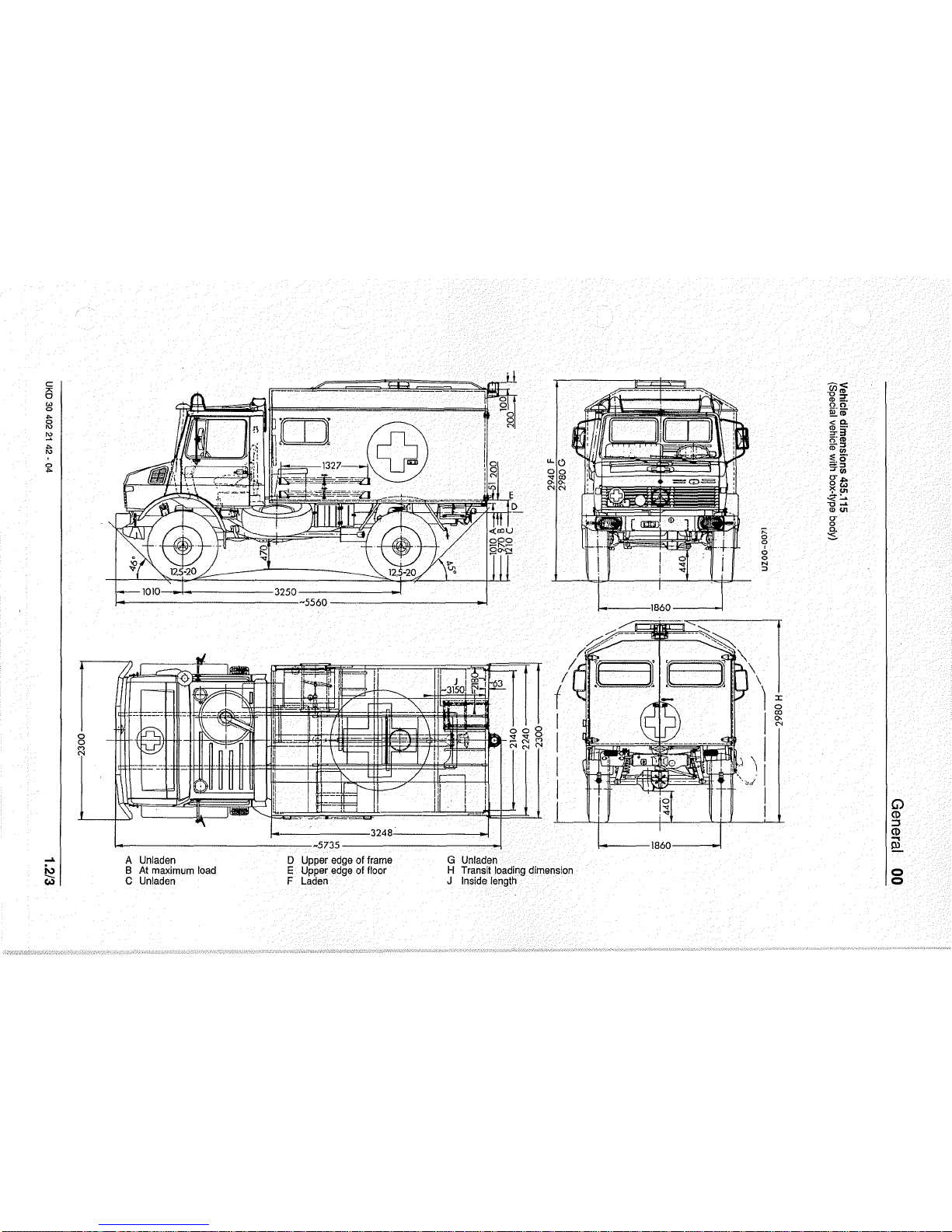
Vehicle
dimensions
435.115
(special
vehicle
with
box-type
body)
Maximum
speeds
435.115/117
Maximum
speeds
435.110/111
Weights
and
trailer
loads
Service
products,
capacities
Special
versions
considered U 1300
L
UKD
30
40021
42
- 04
General 00
Page
1.1/1
1.1/5
1.211
1.212
1.213
1.3/1
1.3/2
1.4/1
1.5/1
1.6/1

General 00
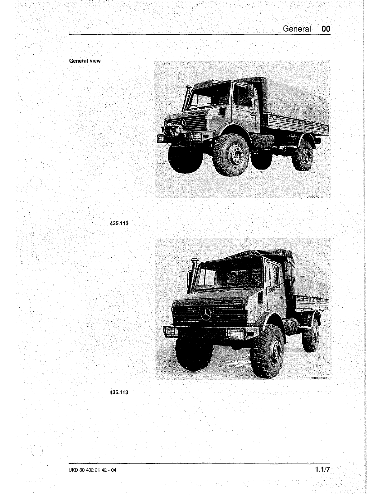
General
view
UROO~01:tR
435.113
435.113
UKD
30
402
21
42 • 04
1.1/7
00 General
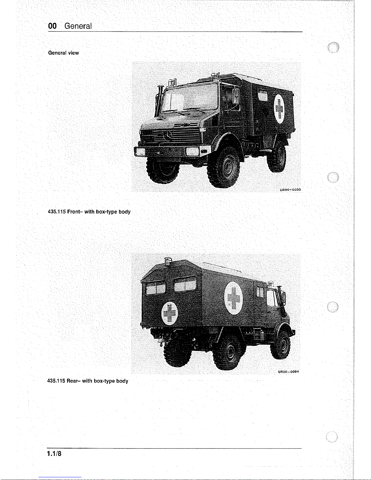
General view
435.115
Front-
with box-type body
435.115
Rear- with box-type body
1.1/8
General 00
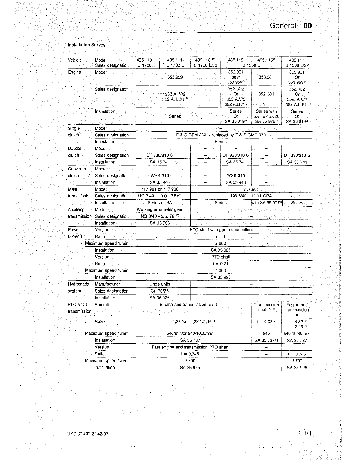
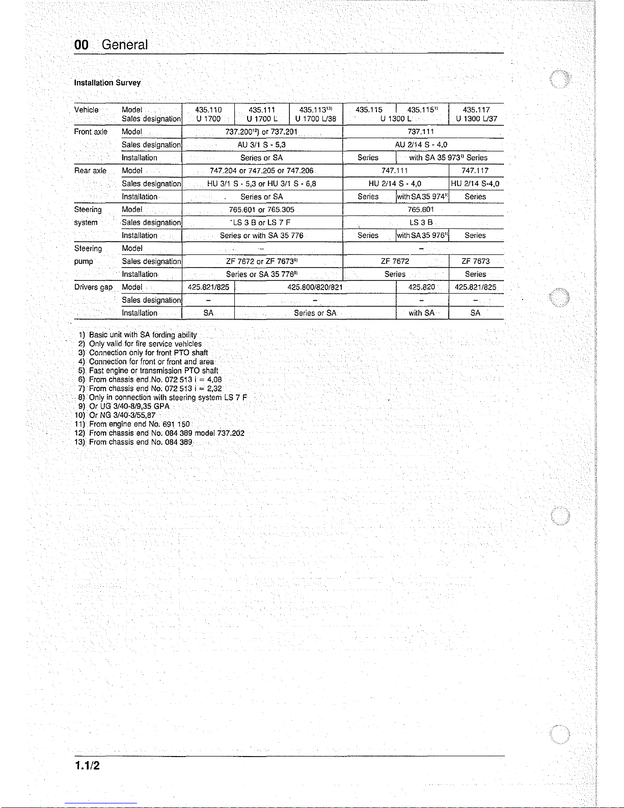
Installation
Survey
Vehicle Model 435.110
I
435.111
435.113
",
435.115 I 435.115"
435.117
Sales designation
U
1700 U 1700 L U 1700
U38
U 1300 L
U
1300
U37
Engine
Model
353.961
353.961
353.959 oder
353.961
Or
353.959"
353.959"
Sales
designation
352. Xl2 .
352. Xl2
352
A.
VI2
Or 352.
Xl1
Or
352
A.
L1111
'"
352
A.V12
352.
A.V12
352.A.L1li1 "
352
A.L1111"
Installation
Series
Series
with
Series
Series
Or SA 16457126 Or
SA
36019"
SA 35
975"
SA 36 019"
Single
Model
. -
clutch Sales designation F & S GFM 330 K replaced by F & S GMF 330
Installation
Series
Double Model
- - - -
-
clutch
Sales designation
DT 3301310 G
-
DT 3301310 G
-
DT 3301310 G
----
Installation SA 35
741
-
SA
35
7!11
-
SA
35
741
Converter Model
-
- - -
-
clutch Sales designation
WSK 310
-
WSK 310
-
Installation SA 35 948
-
SA
35 948
-
Main Model 717.901 or 717.900 7t7.901
transmission
Sales designation UG
3140
- 13,01
GPA"
UG
3140
- 13,01 GPA
Installation
Series or
SA
Series
ft,ith SA 35 977"1
Series
Auxiliary Model Working or crawler gear
-
transmission
Sales designation
NG
3140 -215,
76
'"
-
Installation
SA
35 736
-
Power
Version
PTO shaft with pump connection
iake'off Ratio i
= 1
Maximum speed
1/min
2800
'
..
Instalation SA 35 925
Version
PTO shaft
Ratio i
=
0,71
. Maximum speed 1/min
4000
Installation
SA
35 925
Hydrostatic Manufacturer
Unde units
-
system Sales designation
Gr.
70/75
-
.-----
Installation SA 36 036
-
PTO shaft
Version
Engine
and
transmission
shaft
4)
--,..----.
Transmission Engine
and
transmission
shaft
1]
31
transmission
shaft
..
_---
Ratio
i = 4,32
SI/or
4,32
6)/2,46
7)
i = 4,32 '
I·
4,32
61
2,46 "
---,-"
Maximum speed 1/min 540lmin/or 540/1000/min
540
540:1000Imin.
._-_.
Installation
SA
35 737
SA
35
73714
SA
35737
-
Version
Fast engine and transmission PTO shaft
-
'"
Ratio i = 0,745
-
i"
0,745
Maximum speed 1/min
3700
-
3700
Installation
SA
35 926
-
SA
35
926
UKD
30 402
21
42-03
1.1/1
00 General
Installation
Survey
Vehicle Model 435.110 435.111
I 435.113'"
435.115
I 435.115" 435.117
Sales designation U 1700 U 1700 L U 1700 U38 U 1300 L U 1300 U37
Front axle
Model
737.200") or 737.201
737.111
Sales designation
AU
311
S - 5,3
AU
2114
S - 4,0
Installation Series or SA
Series
with SA 35 973" Series
Rear axle Model 747.204 or 747.205 or 747.206 747.111 747.117
Sales designation
HU
311
S - 5,3 or
HU
311
S - 6,8
HU
2114
S - 4,0
HU
2114
S-4,0
Installation Series
or SA
Series
withSA35974"
Series
Steering Model 765.601 or 765.305 765.601
system
Sales designation
-LS3BorLS7F
LS
3 B
Installation
Series or with SA 35 776
Series
withSA35976"
Series
Steering
Model
-
-
pump Sales designation
ZF 7672 or ZF 7673"
ZF 7672
ZF
7673
.
Installation
Series
or SA 35
776"
Series
Series
Drivers gap Model 425.8211825
425.80018201821
425.820 425.8211825
Sales designation
- - - -
Installation
SA
Series or SA
with SA
SA
1)
Basic unit with SA fording ability
2)
Only valid for fire service vehicles
3)
Connection only for front PTO shaft
4) Connection for front or front and area
5) Fast engine or transmission
PTO shaft
6)
From chassis end.No.
072513
i = 4,08
7)
From chassis end No. 072 513 i = 2,32
8)
Only
.in
connection with steering system
LS
7 F
9)
Or UG
3140-819,35
GPA
10) Or
NG
3140-3155,87
11) From engine end No.
691
150
12) From chassis end
No.
084389
model 737.202
13) From chassis end
No.
084389
1.1/2
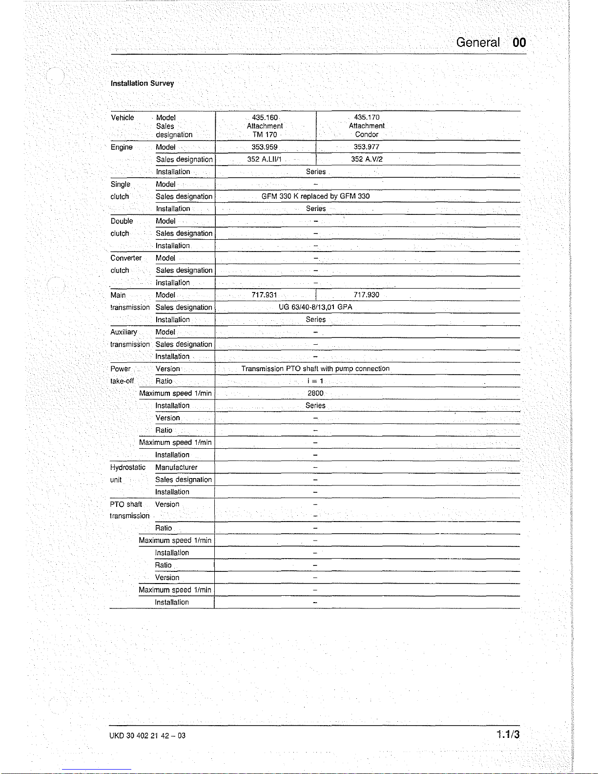
General 00
Installation
Survey
Vehicle
. Model
435.160
435.170
Sales
Attachment
Attachment
designation
TM
170 Condor
Engine Model
353.959 353.977
Sales designation 352 A.LIII1 352 A.V!2
Installation Series.
Single
Model -
clutch
Sales designation
GFM 330 K replaced by GFM 330
Installation
Series
.
Double Model
-
clutch Sales designation
-
Installation -
Converter Model -
.
clutch Sales designation
-
Installation
-
Main Model 717.931
717.930
!ransmission
Sales designation
UG
63/40-8/13,01 GPA
Installation
Series
Auxiliary
Model
-
transmission
Sales designation
-
Installation
-
Power
Version
Transmission
PTO
shaft
with
pump
connection
take·off
Ratio i = 1
Maximum speed
1/min 2800
.
Installation
Series
Version
-
Ratio
-
Maximum speed
llmin
-
Installation
-
Hydrostatic
Manufacturer
-
unit
Sales designation
-
Installation
-
PTO shaft
Version
-
transmission
-
Ratio -
Maximum speed
llmin
-
Installation
-
..
Ratio
-
Version
-
Maximum speed
limin
-
Installation
-
UKD 30 402
21
42 -
03
1.1/3
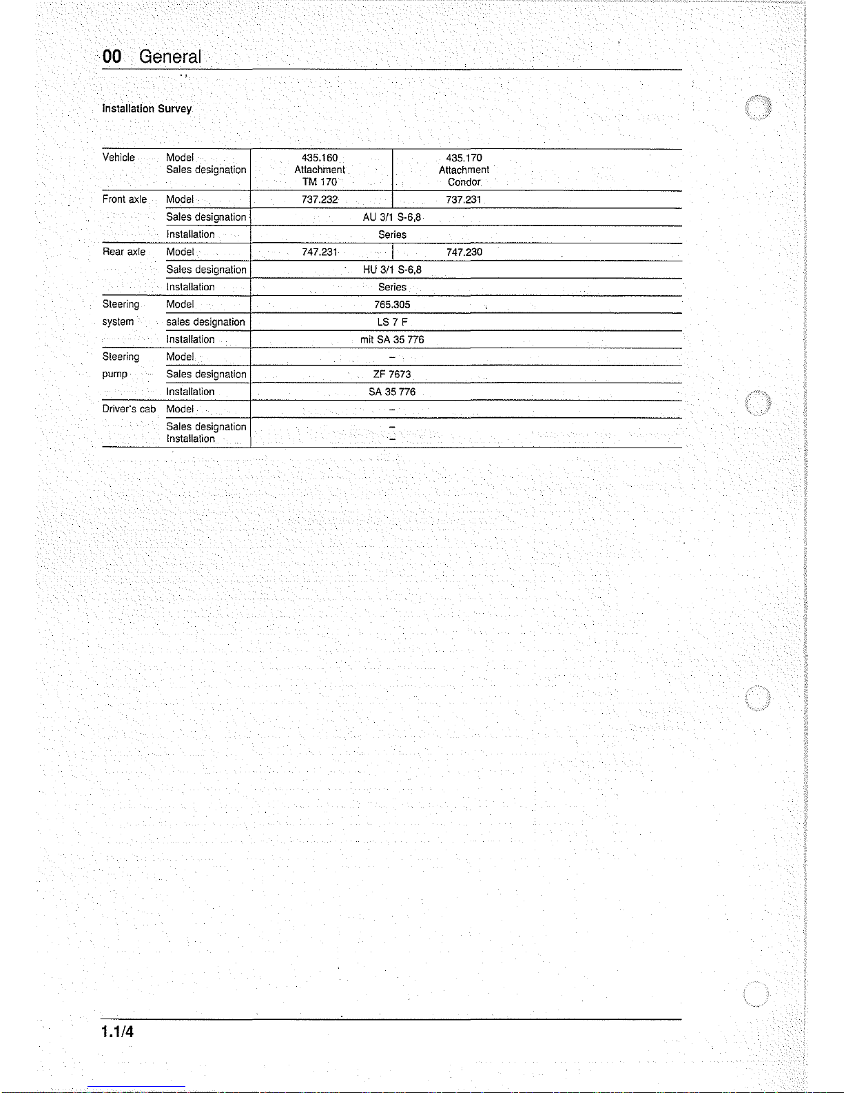
00 General
Installation
Survey
Vehicle Model 435.160
435.170
Sales designation Attachment Attachment
TM 170
Condor
Front
axle Model
737.232 737.231
Sales designalion
AU
3/1
S·6,8
Installation
Series
Rear axle
Model
747.231 747.230
Sales designation
HU
3/1
S-6,8
Inslallalion
Series
Sleering
Model
765.305
system
sales
designation
LS
7 F
Installation
mil
SA 35 776
Sleering Model
-
pump
Sales
designation
ZF 7673
Inslallalion
SA
35 776
Driver's
cab
Model
-
Sales designalion
-
Installation
-
1.1/4
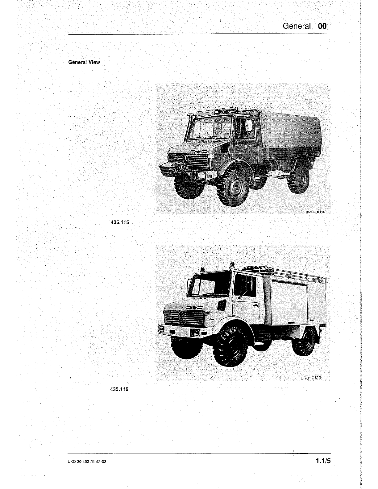
General
00
General
View
435.115
URO-0129
435.115
UKD
30 402
21
42'()3
1.1/5
00 General
General View
URO-0128
435.111
URO-0120
435.111
1.1/6
General
00
Vehicle dimensions
435115
12,5
-20
9,00 - 20
14,5 - 20
Tire
sizes 12,5 R 20
11
9,00 R 20
14,5 R 20
Wheelbase
mm
3250
3250
3250
Track
front
mm 1 860
1
860 1 860
Track rear
mm
1 860
1860
1860
Track circle diameter
mm
12890
12890
12890
Turning circle diameter
mm
13800 13800
13800
Length
without
winch
mm
5540
5540 5540
Length
with
winch
mm
5870 5870
5870
Overall
width
(without
rear·view mirror)
mm
2300
2300
2300
Overall height (unladen)
2830
2880
,
2900
approx. mm
Height above
cab,
unladen
approx. mm
27502)
2630
2650
Ground clearance on a convex surface
approx. mm
470 465 495
Overhang
front,
without
winch
0
46
46 46
Overhang
front,
with
winch
0
40
40
40
Overhang rear
0
51
51
51
approx.
Ground
clearance,
front
axle (laden)
approx.
mm
440 435
465
Ground
clearance, rear axle (laden)
approx. mm
440
435
465
Wading depth
approx. mm
1 220
- -
Permissible height
of
center
of
gravity above
platform
mm
800
-
-
floor
for
2000
kg
payload,
with
stabilier at
front
Height
of
trailer coupling (unladen)
mm
945 950 970
loading
space
Length inside
mm
3150 3150 3150
Width inside
mm
2200
2200
2200
Height
of
side boards
mm
500 500 500
Height beneath canopy
top,
min.
mm 1
370 1 370
1370
Height beneath canopy top, max.
mm
1480
1 480
1480
Loading height above ground -(unladen)'
mm 1 290 1 285
1 315
1) special vehicle
2) with camoftage net support
UKO
30
402
21
42-02
1.2/1
00
General
Vehicle dimensions 435.110/.111/.113
Tire sizes
mm
14}5/80
R
201)2)
12.5R22.5
14.5
- 20
12.00 R 20
14.5 R 20
16/17-24
13 R 22.5
14.75/80
R
20
1
)
Wheelbase mm
3850
3250
3250 3250
Track
front
mm
1840
1840
1 840 1 890
Track rear
mm
1840
1 840
1840
1 890
Track
circle diameter
mm
-
12880
12880
12930
Turning circle diameter mm
15800
14200
14200
14200
Length
without
winch
mm
5580
5345 5345 5345
Length
with
winch approx. mm
6500
-
-
-
Overall
width
(without
rear·view morror) mm
2350
2350 2350
2350
Overall
width
(with
rear·view morror)
mm
2465 2465
2465
2465
Overall height, unladen
approx. mm
3050
3030
3010
3050
Ground clearance on a convex surface,
unladen
approx. mm
680
660 640 680
Overhang
front
0
48 50
50
50
approx.
Overhang rear
0
47
approx.
-
-
-
Ground clearance,
front
axle (laden)
approx. mm
520
500
480
520
Ground clearance; rear axle (laden) approx. mm
520
500 480
520
Wading depth approx. mm 1 200 1 200
1200
1 200
Height
of
trailer coupling (unladen) mm
1050
1050
1050
1 070
Loading
space
Length inside
mm
4050
3 150
3
)
3 150
3
)
3150
3
)
Width inside
mm
2350
2200
2200
2200
Height
of
side
boards
mm
500
500 500 500
L.oading
height above ground (unladen)
mm 1
500 1 480
1460
1 500
1;
13.>:'0
- 20 Pilate
XL
2)
435.113
3)
at
L~35.110
opti'onal2050, 2550,
3000
'1.2/2
c
"
o
'"
o
"
:;l
'Y
I:>
~
......
~
------.-==--~~-~
0'
"-
....
JC[]
ffi\
• I • 3250 • I
I-
-5560 • I
A Unladen
B At maximum load
C Unladen
o Upper edge of frame
E Upper edge of floor
F Laden
iil
f
I
I
I
II
I I I I I
G Unladen
H Transit loading dimension
J Inside length
= , -
;;:
o
o
,
o
o
N
:::>
\
I ;
I~
, \ I
-<
(JJ
..
"O::r
<1>
_,
Q.2.
!!C
..
<e:
~3
_
...
!2"
<1>
en
:; 0'
;::;'::l
::Ten
0'
....
0""
Xu.
~~
"0
~
mu.
8:
:::.
G)
CD
::J
CD
@
o
o

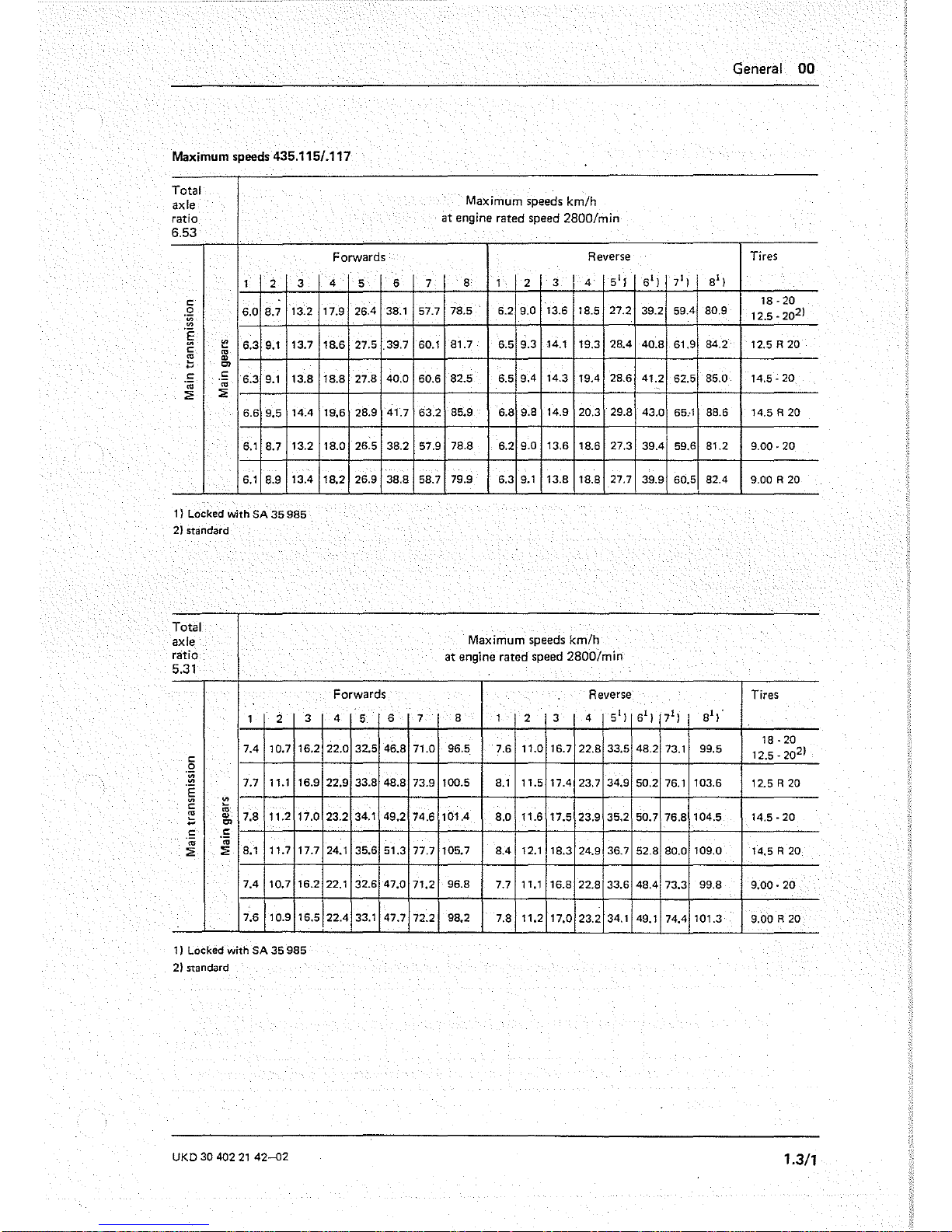
Maximum speeds 435.115/.117
Total
axle
ratio
6.53
1 2
3
c:
.~
6.0
8.7
13.2
~
.~
t::!
6.3
9.1
13.7
c:
'"
b
"
Cl
.S
c:
6.3
9.1
13.8
'"
.;;
:;;
:;;
6.6
9.5
14.4
6.1
8.7
13.2
6.1
8.9
13.4
1) Locked with
SA
35
985
2} standard
Total
axle
ratio
5.31
1 2
3
7.4
10.7
16.2
c:
.~
7.7
11.1 16.9
'E
c:
~
:;;
b
"
7.8
11.2
17.0
Cl
.S
.S
'"
'"
:;;
:;;
8.1 11.7
17.7
7.4
10.7
16.2
7.6
10.9 16.5
1)
Locked with
SA
35
985
2) standard
UKD
30
402
21
42--D2
Forwards
4
5
6
17.9 26.4 38.1
la6
27.5
.39.7
18.8
27.8
40.0
19.6
28.9
41.7
18.0
26.5
38.2
18.2
26.9
38.8
Forwards
4
5
6
22.0
32.5
46.8
22.9
33.8
48.8
23.2
34.1
49.2
24.1
35.6
51.3
22.1 32.6
47.0
22.4
33.1 47.7
7
57.7
60.1
60.6
63.2
57.9
58.7
7
71.0
73.9
74.6
77.7
71.2
72.2
General
00
Maximum speeds km/h
at
engine rated speed 2800/min
Reverse
Tires
8 1 2 3
4
51
f
61) 71 )
81)
18·20
78.5
6.2
9.0
13.6
18.5
27.2
39.2 59.4
80.9
12.5 -
20
2
)
81.7
6.5
9.3
14.1
19.3
28.4
40.8
61.9
84.2
12.5 R
20
82.5
6.5
9.4
14.3
19.4
28.6
41.2
62.5
85.0 14.5 -
20
85.9
6.8
9.8
14.9
20.3
29.8
43.0
65
..
1
88.6 14.5 R
20
78.8
6.2
9.0
13.6
18.6 27.3
39.4
59.6
81.2
9.00·20
79.9
6.3
9.1
13.8
18.8 27.7
39.9
60.5
82.4
9.00 R 20
Maximum speeds km/h
at engine rated speed
2800/min
Reverse
Tires
8 1
2 3
4
51
)
61 ) 71)
81,'
96.5. 7.6
11.0 16.7
22.8
33.5
48.2
73.1
99.5
18 -
20
12.5 - 20
21
100.5
8.1
11.5 17.4
23.7
34.9
50.2
76.1
103.6
12.5R20
101.4
8.0
11.6 17.5
23.9
35.2
50.7
76.8
104.5
14.5 -
20
105.7
8.4
12.1 18.3
24.9
36.7
52.8
80.0
109.0
14.5 R 20
96.8
7.7 11.1 16.8
22.8
33.6
48.4
73.3
99.8
9.00 -
20
98.2
7.8 11.2
17.0
23.2
34.1
49.1 74.4
101.3
9.00
R 20
1.3/1
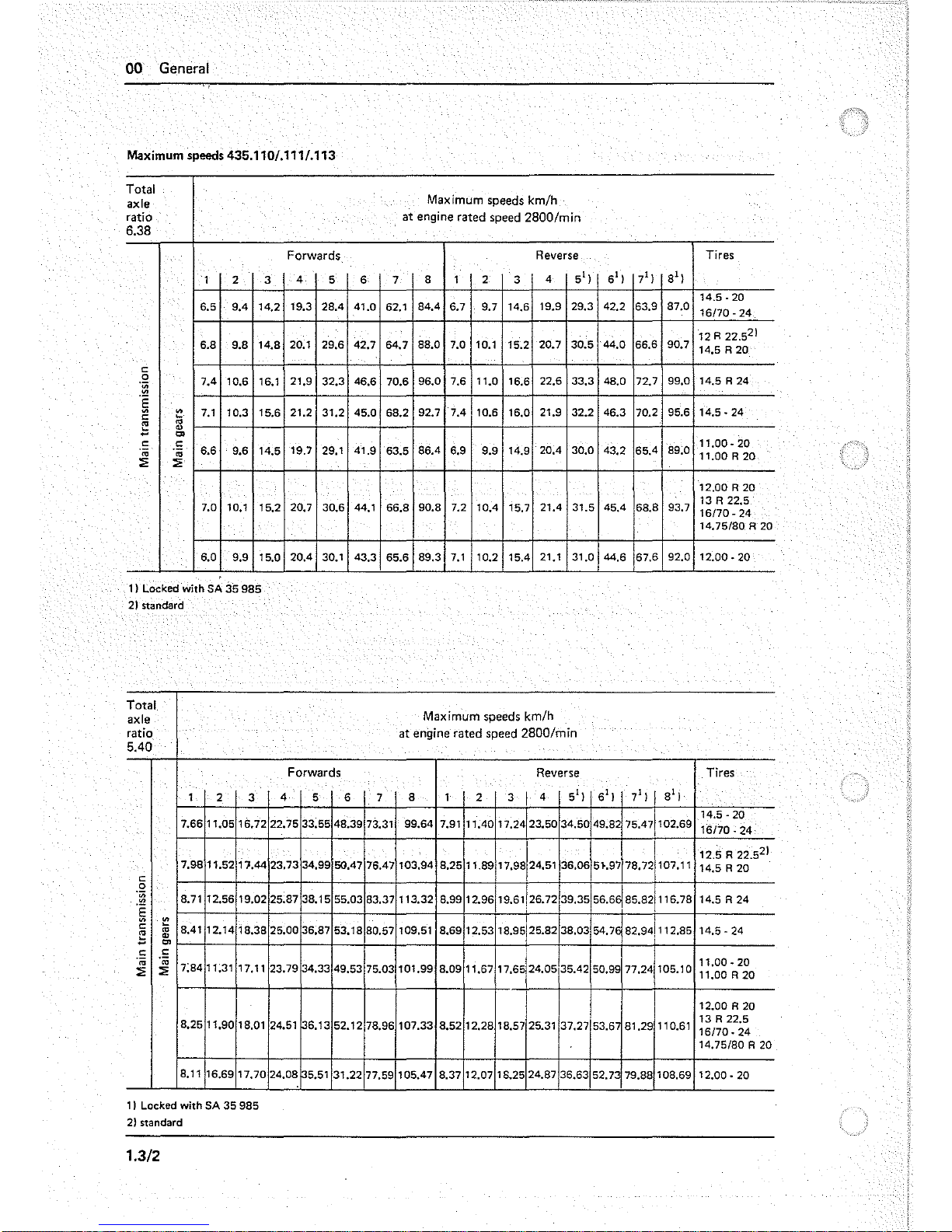
00 General
Maximum
speeds 435.110/.111/.113
Total
axle
Maximum speeds km/h
ratio at engine rated speed
2800/min
6.38
Forwards
Reverse
1 2 3
4
5 6 7
8 1 2
3
4
5'}
6'}
7'
}
8'}
6.5
904
14.2 19.3 2804
41.0
62.1
84.4
6.7 9.7 14.6
19.9 29.3
42.2
63.9
87.0
6.8
9.8
14.8
20..1
29.6
42.7
64.7
88.0
7.0
10..1
15.2 20.7 30..5 44.0.
66.6
90..7
c:
0
7.4
10..6 16.1
21.9
32.3
46.6
70..6
96.0.
7.6 11.0.
16.6
22.6
33.3
48.0 72.7
99.0
oB;
"§
~
7.1
10.3 15.6
21.2
31.2
45.0.
68.2
92.7
704
10..6
16.0
21.9 32.2
46.3
70..2 95.6
c:
~
..
"
'"
c:
c:
.n;
.n;
6.6
9.6
14.5
19.7
29.1
41.9
63.5
86.4
6.9
9.9
14.9
20.04
30.0
43.2
65.4
89.0
:2 :2
7.0
10..1
15.2
20..7
30..6
44.1
66.8
90..8 7.2
lOA
15.7
21.4
31.5
4504
68.8
93.7
6.0.
9.9
15.0.
20.04
30..1
43.3
65.6
89.3
7.1
10.2
1504
21.1
31.0
44.6
67.6
92.0
I} Locked with SA
:is
985
2)
standard
Total
axle
ratio
5.40
1
2
3
7.66
11.0.5
16.72
7.98
11.52
17.44
c:
0
.~
8.71 12.56
19.0.2
.~
~
c:
:;;
8041
12.14
18.38
~
"
~
Cl
.!:
c:
'"
.n;
7;84 11;31
17.11
:2
:2
8.25
11.90.
18.0.1
8.11
16.69
17.70.
1}
Locked with SA
35
985
2} standard
1.3/2
Forwards
4
5 6 7
22.75
33.55
48.39 73.31
23.73
34.99
50047
76.47
25.87
38.15
55.0.3
83.37
25.00
36.87
53.18
80.57
23.79
34.33
49.53 75.0.3
24.51
36.13
52.12
78.96
24.08
5.51
31.22
77.59
Maximum speeds km/h
at
engine rated speed 2800/m
in
Reverse
8 1
2 3
I
4
5'
}
6'}
7'}
I
8'}
99.64
7.91
11040.
17.24
23.50
34.50. 49.82
75047
102.69
17.98/24.51
I
10.3.94
8.25
11.89
36.06
5}.97
78.721107.11
113.32
8.99
12.96
19.61 26.72
39.35
56.6~
85.821,,6.78
I
f
109.51
8.69
12.53
18.95125.82
38.0.3 54.76
82.941112.85
10.1.99 8.0.9
11.67
17.65124.05
35042
50.99
77.24
105.10
107.33
8.52
12.28
18.57
25.31
37.27153.6
81.29
110.61
105.47
8.37 12.07 18.25
24.87
36.63
52.73 79.88 108.69
Tires
14.5·20
16170.·24
12 R 22.5
2
}
14.5
R2o.
14.5
R 24
14.5·24
11.0.0.·20.
11.DDR2D
12.00R2D
13R22.5
16170.·24
14.75/80 R 20
12.00.·20.
Tires
14.5·20
16/70.·24
12.5
R 22.52}
14.5 R 20
14.5 R 24
14.5·24
11.00·20
11.0.0. R 20
12.00R20
13 R 22.5
16170.·
24
14.75/80 R 20
12.00.·20.
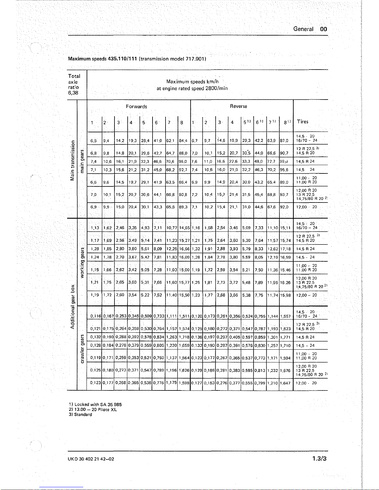
General 00
Maximum speeds 435.110/111 (transmission model 717.901)
Total
axle
Maximum speeds km/h
ratio
at
engine rated speed 2800/min
6,38
Forwards
Reverse
1 2 3 4 5 6
7
8
1
2
3 4
5"
6"
7"·
8
'1
Tires
14.6
14,5 ' 20
c:
6.5
9.4
14.2
19.3
28.4
41.0
62.1 84.4
6.7
9.7
19.9
29.3
42.2
63.9 87.0
16170 - 24
.~
12
R 22.5
3)
~
~
30;5
.~
'"
6.B
9.8
14,8
20.1
29.6
42,7
64,7
88.0 7.0 10.1
15.2
20,7
44.0
66.6
90.7
14.SR20
<1>
c:
'"
7.4
10.6
16,1
21,9
32,3
46,6
70,6
96,0
7.6
11,0
16,6
22.6
33,3
48,0
72.7
99.0
14.SR24
t:
c:
'm
c:
.E
7.1
10.3 15.6 21.2
31,2
45,0
68.2
92,7
7.4
10.6
16,0
21.9
32.2
46.3
70,2
95.6
14,5
24
'm
:2
11,00
¥ 20
6.6
9.6
14,5
19,7
29,1
41,9
63,5
86,4
6.9 9.9
14,9
20,4
30.0
43,2
65,4
89.0
11,OOR20
12.00A20
7.0
10.1 15.2 20.7
30.6
44,1
66.8
90.8 7.2
10,4
15.7
21.4
31,5
45,4
68.8
93,7
13 R 22,5
14.75/80 R 20
2;
6.9 9.9
15,0
20,4
30,1
43,3
65.6
89.3
7.1
10,2
15,4
21,1
31.0
44,6
67,6
92.0
12,00
20
14.5·
20
1,13
1.62
2,46
3.35
4,93
7,11
10,77
14,65
1,16
1,68
2,54
3.46
5.09
7,33
11,10
15,11
16170 - 24
12R22.5
3
}
1.17
1.69
2.56
3.49
5.14
7.41
11.23
15.27 1.21
1.75
2.64
3.60
5.30
7,64
11.57 15.74 14.5
A20
~
1,28
1,85
2.80
3.80
5.61 8.09
12.25
16,66
1.32 1,91 2.88
3,93
5.79
8.33
12.62
17,18
14,5 A 24
'"
<1>
'"
1
,24
1
,78
2.70
3.67
5.42
7,81
11.83
16,09
1,28
1,84
2.78
3.80
5.59
8.05
12,19
16.59
14.5 -24
'"
c:
11.00 .. 20
:;;
0
1.15 1.66 2.62
3.42
5.05 7.28
11.03
15.00
1,19
1.72
2.59
3.54
5.21
7.50 11.36 15.46
11.00 A 20
;:
12.00A20
1,21
1.75
2.65
3.60
5.31 7.66
11.60
15.77
1.25
1.81 2.73
3.72
5.48 7.89
11.95
16.26
13A22.5
x
1,4.75/80 R
20
2
)
0
.c
~
1,19
'"
1.72
2.60
3.54
5.22 7.52
11.40
15,50
1.23
1.7
7
2.68
3.66
5.38
7.75
11.74
15.98
12.00
-'
20
<1>
'"
m
c:
14,5
20
:~
0.116
0.167 0.253 0.345 0.509
0.733
1,11 1 1,511
0.120
0,173
0.261
0.356
0,524
0.755
1,144
1.557
16170-
24
'0
12R22,5
31
'0
<>:
0.121
0,175
0.264
0.359
0.530 0.764
1.157 1.574
0.125 0.180
0.272
0.371
0.547 0.787
1.193
1.623
14,5 A 20
~
0,132
0,190
0,288
0.392
0.578 0.834
1,263
1,718
0,136
0,197
0.297
0.405
0.597 0.859
1,301
1,771
14,5 R 24
~
'"
<1>
'"
0.128
0,184
0.278
0,379
0.559 0.805
1.220
1.659
0,132
0,190
0.287
0.391
0.576 0.830
1,257 1,710
14,5 -24
~
<1>
~
11,00 -20
'"
0,119
0.171 0.259
0.353
0.521
0.750
1,137
1.564
0,123
0.177 0.267
0.365
0,537
0,773
1 ,171
1.594 11.00 A 20
t;
12,OOR20
0.125
0,180
0,273
0,371
0.547 0.789
1,196
1,626
0,129
0.186
0.281
0.383
0.585
0.813
1,232
1,676
13 R 22,5
14.15/80
A 20 "
0.123
0,177
0.268 0.365
0.538
0.776
1.175
1,598
0,127 0,183
0.276
0,377
0.555 0.799
1,210 1,647
12,00
- 20
1) Locked
with
SA
35
985
2)
13.00 -20
Pilote
XL
3) Standard
UKD
30
402
21
42-02
1.3/3

00
General
Maximum speeds 435.110/.111 (transmission model 717.900)
Total
axle
Maximum speeds
km/h
ratio
at engine rated speed
2800/min
6,38
Forwards
Reverse
1 2 3
4
5
6
7 8
1 2 3
4
51:
6"
7"
8"
Tires
14,5 -
20
c
9.0
12.5 17.1
0
23.3
32.7
45.4
62.1
84,4
9,3
13,0
17,7
24,1
33,8
46,9
64,0
87,0
16170
74
.~
12 A 22,5
31
.~
~
9,4
13.1
17,9
24.3
34.1
47,3
64.7
88.0
9.7
13,5
18,4
25.1
35,2
48,9
66.7
90.7
14,5 R
20
~
'"
c
"
10,3
14.3
19.5
26,5 37,2
51,6
70,6
96.0
10,6
14.7
20.1
27,4
38.4
53,4
72,8
99.0
14,5 R
24
E
on
~
C
,S
'0;
9.9
13,8
18,8
25.6
35.9
49.8
68.2
92,7
10,2 14.2
19,4
26.4
37.1
51.5
70.3
95.6
14,5
24
'"
E
:;:
11,00 -20
9,2
12.8
17,5
23,9
33.4
46.4
63,5
86.4
9.5
13.3
18,1
24,6
34.6
48,0
65,5
89.1
11,00 A 20
12.00
A 20
9,7
13.5
18,4
25,1
35,2
48.9
66,8
90.9
10,0
13,9
19.0 25,9
36,4
50.5
68.9
93,7
13 R 22.5
14,75/80
R 20
21
9.6
13,3 18,1
24,7
34,6 48,0
65.6
89,3
9,9
13,7
18.7
25,4
35,7
49,6
67,7
92,1
12,00 -20
14,5 - 20
1.57
2,18
2,97
4,05
5.68
7,88
10,78
14.66
1,62 2,25
3.07
4,18
5,86
8,14 11,11 15,11 16170 24
12R22.5
3l
1.63
2;27
3,10
4,22
5,92
8,21
11,23
15.28
1.69
2,34
3,20
4.35
6.11
8.49
11,57
15.75
14,SR20
~
:;;
1,78
2,48
3.38
4.61 6,46
8.96
12,26
16,67
1,84
2,56
3A9
4,75
6,67
9,26
12.63
17,19
14,5 R 24
"
on
1,72
2.39
3.27
4.45
6,24
8.66
11,84 16,10
1,78
2,47
3,37
4,59
6,44
8,94
12,20 16,60
14,5 - 24
on
t:
""
11,00
20
"
1 ,60 2,23 3,04
4,14
5,81
8.07
11,03 15,00
1.66
2,30
3.14
4,27
6,00
8,33
11,37
15,47 11.00
R 20
;:
12,00 A
20
x
1,69 2,34
3.20
4,36
6.12
8.48
11,60
15,78
1.74
2.42
3,30
4,50
6,31
8,77
11,95 16,27
13 R 22,5
0
14,75/80 R 20
2J
.0
~
1.66
2.30
3.15
4,28
6,01
8,34
11,40
15,51
2,38
4,42
6,20
11.75 15.98
12,00 - 20
'"
1 ,71
3,24
8.61
"
on
-;;;
c
0
14,5·
20
.;:;
0,162
0.225
0.307
0,418
0,586
0,813
1,111 1,511
0.167
0,232
0,316
0,431
0,605
0,840
1,145
1,558
16/70 -24
'0
'0
«
12 R 22.5
3)
0,168
0,234
0,319
0,435
0,610
0.847
1,158
1.575
0.174 0,242
0,330
0.449
0,630
0.875
1.193
1,624 14.5 A
20
~
0.184
0,255
0,349
~
0,475
0,666
0.924
1.264 1,719
0,190
0,264
0,360
0,490
0,688 0,955
1,302
1.772
14,5 R 24
'"
"
0.178
0,247
0,337
0,459 0,643
0,892
1,221
1,660
0.183
0,255
0,347
0,473
0664
0,922
1,258 1,711 14,5 -
24
C>
~
"
11,00-
20'
~
0,165
0.230
0.314 0,427
0,600
0,832
1.137 1,547 0,171
0,237
0.324
0,441 0,619
0.859
1,172
1.595
11.00 R 20
E
u
12.00 R 20
0,174
0.242
0,330
0.449
0.631
0,875
1,196
1.627
0,180
0,250
0,340
0.463
0,651
0,904
1.232
1,677
13 R 22.5
14,75/80 R 20
2)
0,171
0,238
0.324
0,442
0,620
0,860
1.175
1,600
0,176
0.245
0,334
0,455
0,693
0,888
1211
1,648
12,00
- 20
1) Locked with SA
35985
2) 13.00 -
20
Pilot.
XL
3) Standard
1.3/4
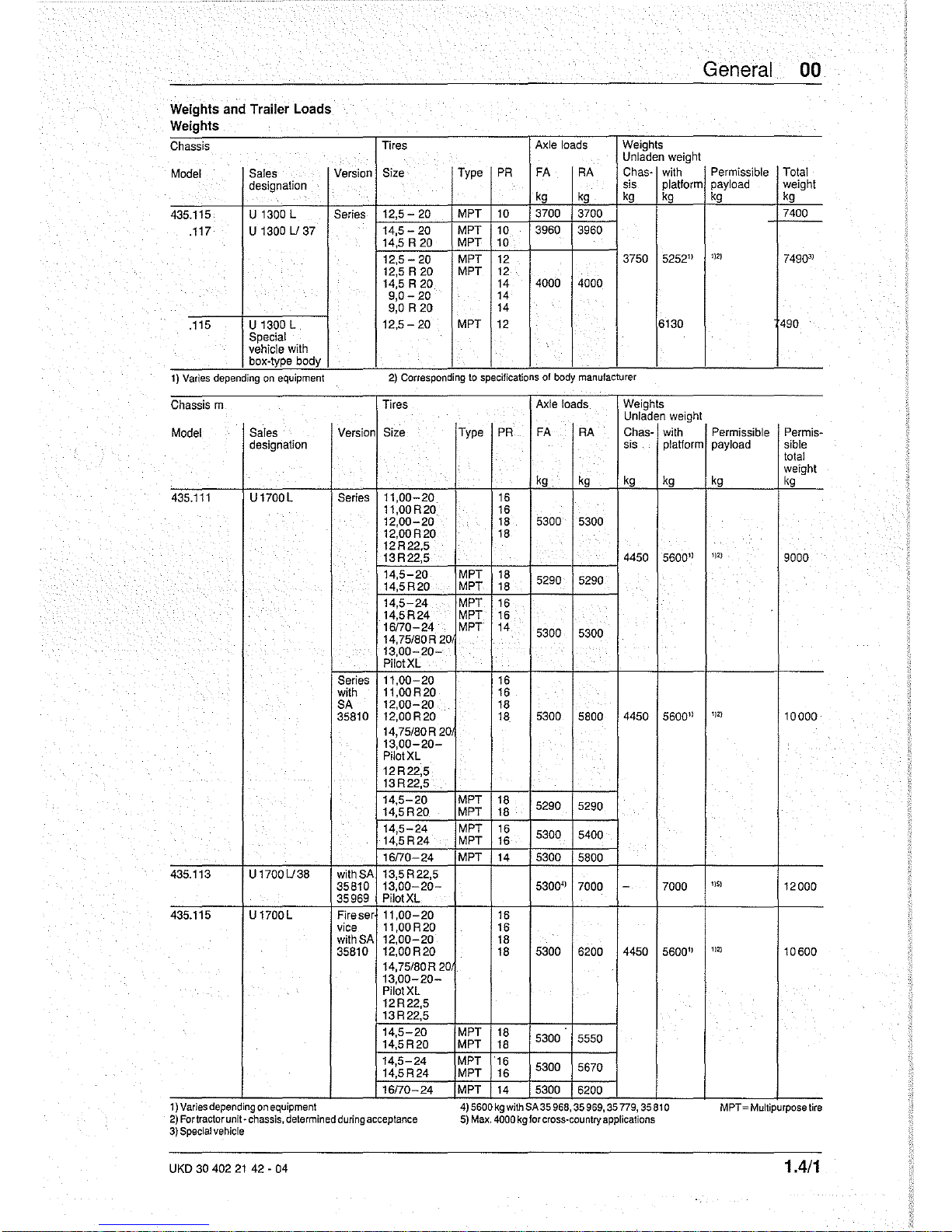
Weights
and
Trailer
Loads
Weights
Chassis
Model
Sales
designation
435.115 U
1300 L
.117
U1300U37
.115 U 1300 L
Special
vehicle with
box-type body
Tires
Version
Size Type
Series
12,5 - 20
MPT
14,5 -
20
MPT
14,5 R
20
MPT
12,5-20
MPT
12,5 R
20
MPT
14,5 R
20
9,0-
20
9,0
R 20
12,5 - 20 MPT
Axle loads
Weights
Unladen weight
PR
FA
RA
Chas-
with
sis
plaHorm
kg kg
kg
kg
10
3700 3700
10
3960 3960
10
12
3750
5252"
12
14
4000 4000
14
14
12
6130
>
1)
Varies
depending
on
equipment
2)
Corresponding
to
specificatIOns
of
body
manufacturer
Chassis m
Tires
Axle loads
Weights
Unladen weight
Model
Sales
Version
Size Type
PR
FA
RA
Chas-
with
designation
sis
platform
kg
kg
kg
kg
435.111
U1700L
Series
11,00-20
16
11,00
R20
16
12,00-20
18
5300
5300
12,00R20
18
12R22,5
13R22,5
4450
5600"
14,5-20
MPT
18
5290 5290
14,5R20
MPT
18
14,5-24
MPT 16
14,5R24
MPT
16
16170-24 MPT 14
5300
5300
14,75/80R 20
13,00-20Pilot XL
Series
11,00-20
16
with
11,00R20 16
SA
12,00-20
18
35810 12,00R20
18.
5300
5800
4450
5600"
14,75/80R 20
13,00-20Pilot XL
12R22,5
13R22,5
14,5-20
MPT
18
5290 5290
14,5R20
MPT
18
14,5-24
MPT
16
5300 5400
14,5R24
MPT
16
16170-24 MPT
14
5300
5800
435.113
U1700U38
with SA 13,5R22,5
35810
13,00-20-
5300" 7000
-
7000
35969 Pilot XL
435.115
U1700L
Fireser
11,00-20
16
vice
11,00R20 16
with
SA
12,00-20
18
35810
12,00R20
18
5300
6200
4450
5600"
14,75/80R
20
13,00-20-
Pilot XL
12R22,5
13R22,5
14,5-20
MPT
18
5300
5550
14,5R20
MPT
18
14,5-24
MPT
·16
5300
5670
14,5R24
MPT 16
16170-24 MPT
14
5300
6200
1)
Vanes
depending
on
equipment
4)
5600
kg
with
SA35
968,
35
969,
35
n9,
35810
2)
Fortractor
unit·
chassis,
determined
during
acceptance
5)
Max.
4000
kg
for
cross-country
applications
3)
Special
vehicle
UKD 30 402
21
42 - 04
General 00
Permissible
Total
payload weight
kg kg
7400
1)2)
7490"
490
Permissible
Permis-
payload sible
total
weight
kg
kg
1)2)
9000
I
1)2)
10000
I)S)
12000
1)2)
10600
MPT
=Multlpurpose
tlr8
1.4/1
00 General
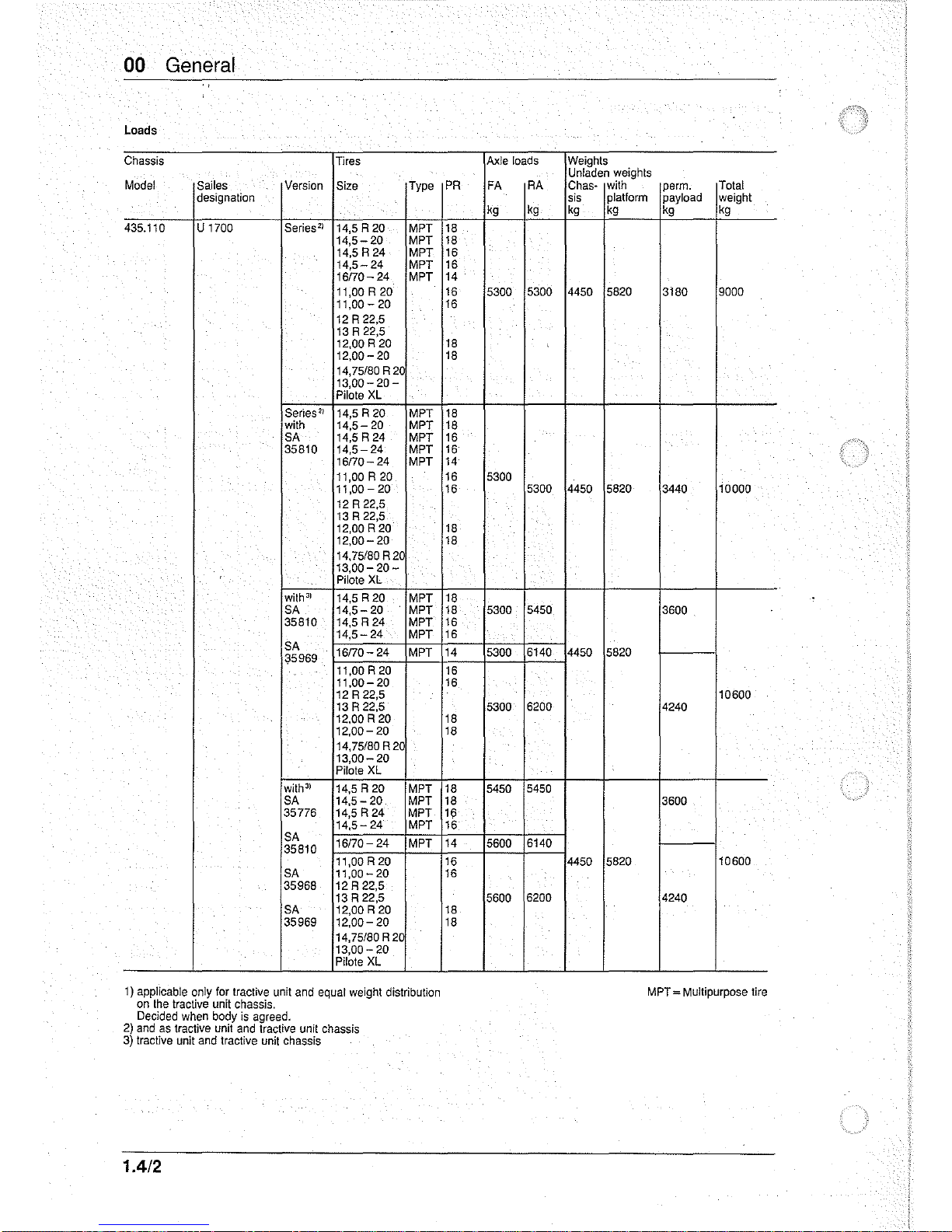
Loads
Chassis
Tires
Model Sailes
Version
Size Type
designation
435.110 U
1700
Series
Z
)
14,5 R 20 MPT
14,5-20
MPT
14,5 R 24
MPT
14,5-24
MPT
16170-24
MPT
11,00 R 20
11,00-
20
12 R 22,5
13 R 22,5
12,00 R
20
12,00-20
14,75/80 R
20
13,00-
20-
Pilots
XL
Series
Z
)
14,5 R 20 MPT
with
14,5-20
MPT
SA 14,5 R 24
MPT
35810
14,5-24
MPT
16170-24
MPT
11,00 R 20
11,00-20
12 R 22,5
13 R 22,5
12,00 R
20
12,00-20
14,75/80R20
13,00-
20-
Pi
late
XL
with
J
)
14,5 R 20
MPT
SA
14,5-
20 MPT
35810 14,5 R 24 MPT
14,5-24
MPT
SA
16170- 24
MPT
35969
11,00 R
20
11,00-20
12 R 22,5
13 R 22,5
12,00 R
20
12,00-20
14,75/80 R 20
13,00-20
Pilote
XL
with
3
)
14,5 R 20
MPT
SA 14,5 - 20 MPT
35776 14,5 R 24 MPT
14,5-24
MPT
SA
16170- 24
MPT
35810
11,00R20
SA
11,00 -
20
35968
12R22,5
13
R 22,5
SA 12,00 R
20
35969
12,00-
20
14,75/80 R
2C
13,00-
20
Pilote
XL
1)
applicable only for tractive unit and equal weight distribution
on
the
tractive
unit
chassis.
Decided when body
is
agreed.
2)
and
as
tractive unit
and
tractive unit chassis
3)
tractive unit and tractive unit chassis
1.4/2
Axle loads Weights
Unladen weights
PR
FA
RA
Chas- with
perm.
Total
sis
platform
payload weight
kg
kg kg kg kg kg
18
18
16
16
14
16
5300
5300
4450 5820 3180 9000
16
18
18
18
18
16
16
14
16
5300
16
5300 4450 5820
3440
10000
18
18
18
18
5300
5450
3600
16
16
14
5300 6140 4450 5820
16
16
10600
5300
6200 4240
18
18
18
5450
5450
18
3600
16
16
14
5600
6140
16
4450 5820
10600
16
5600
6200
4240
18
18
MPT = Multipurpose tire

General 00
Authorized towed weights
Trailers with brakes
Chassis
Trailer, gross weight
Model
Sales
Gross weight of
with
non-continuous with continuous brake
. designation
towing vehicle brake (over-run brake)
kg
kg
kg
435.115 U 1300 L
.
7490
7020
to
7500
10480
435.111 U 1700 L
9000
12600
10 000
8000
14000
10600
14840
Trailers without brakes
Chassis
Trailer
Model
Sales
Gross weight of towing Gross weight
designation vehicle
kg kg
435.115
U 1300 L
7490
2300
435.111
U 1700 L
9000
10000
2000
10600
Trailers with brakes
Chassis
41
Trailer, gross weight Trailer
Model
Sales
Gross weight
of
with non-continuous
with coninuous
coupling
11
designation
towing vehicle
brake (over-run brake)
brake
.
kg kg kg
9000
29000
all
10000
3
)
8000
28000
435.110 U 1700
10600
1131
25600
64G
1350r
605
10600
2131
27400
225G
110
.113
U 1700 L/38
12000
-
12000
64 G 135
1)
see
technical data
31.3
-1.1/1
Trailers without brakes
Chassis
41
Trailer
Model
Sales
Gross weight of towing
Gross weight
designation
vehicle
kg
kg
9000
10 000
31
2000
435.110 U 1700
106001)31
10600
2131
435.113
U 1700 L/38
12000
2500
1) with reinforced rear axle
2) with reinforced
rear-
and
front axle
and
steering
LS
7 F.
SA
35968.
SA
35969,
SA
35
776
31
exhaust
brake
SA
35
810
4)
tractor and chassis tractor
UKD
30
402
21
42-02
1.4/3

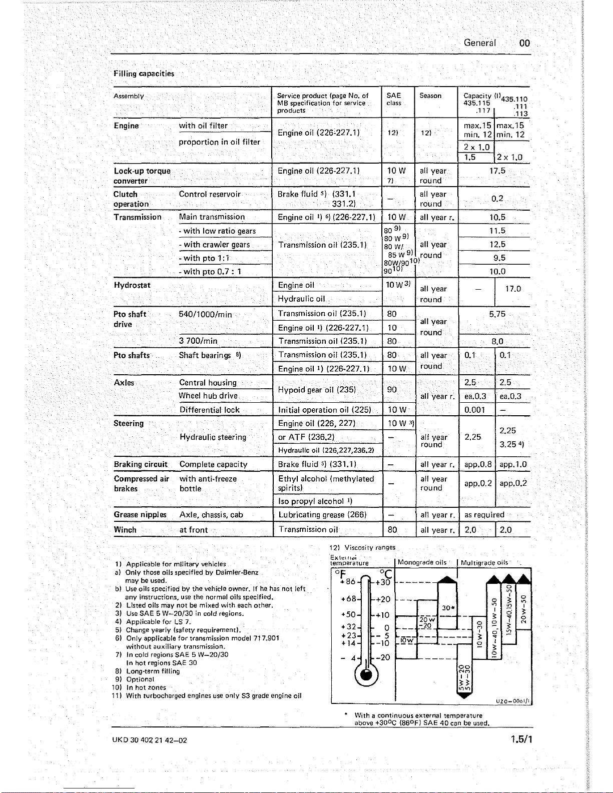
Filling capacities
Assembly Service product (page No.
of
SAE
Season
MS specification for service class
products
Engine with
oil
filter
Engine oil (226·227.1)
121
121
proportion
in
oil filter
Lock·up
torque
Engine oil (226·227.1)
lOW
all
year
converter
71
round
Clutch Control reservoir
Brake fluid
S)
(331.1
all
year
-
operation
331.2)
round
Transmission
Main
transmission
Engine
oil
1)
6)
(226·227.1)
lOW
all
year
r.
· with low ratio gears
80
91
- with
crawler
gears
Transmission oil (235.1)
80w
91
all
year
80
W/
· with
pto
1:1
85 W
91
round
80Wd90101
· with
pto
0.7
: 1
901 I
Hydrostat Engine oil
lOW3)
all
year
.
Hydraulic oil
round
Pto shaft
540/1000/min
Transmission oil (235.1)
SO
drive
Engine
oil
1)
(226·227.1)
10
all
year
round
3700/min
Transmission oil (235.1)
SO
Pto shafts
Shaft bearings
8)
Transmission oil (235.1)
SO
all
year
.
Engine oil
1)
(226-227.1)
lOW
round
Axles
Central housing
Wheel hub drive
Hypoid gear
oil
(235)
90
all
year
r.
Differential lock
Initial operation oil (225)
lOW
Steering Engine oil
(226.227)
10 W
3)
Hydraulic steering
or
ATF (236.2)
Hydraulic
oil
1226,227,236.21
-
all
year
round
Braking circuit Complete capacity
Brake fluid
5)
(331.1)
-
all
year
r.
Compressed air
with
anti· freeze
Ethyl alcohol (methylated
all
year
brakes bottle
spirits)
-
round
Iso
propyl alcohol
1)
Grease nipples
Axle, chassis, cab
Lubricating grease (266)
-
all
year r.
Winch
at
front
Transmission
oil
SO
all
year
r.
121
Viscosity
ranges
1) Applicable
for
military
vehicles
a)
Only those oils specified by Daimler·Benz
may be used,
b)
Use oils specified
by
the vehicle owner.
If
he
has
not left
any
instructions,
use
the normal oils specified.
2) Listed oils may
not
be mixed with each other.
3)
Use
SAE 5
W-20/30
in
cold regions.
4)
Applicable for LS 7.
5)
Change
yearly (safety requirement>.
6)
Only applicable for transmission model 717.901
without auxiliary transmission.
7)
In cold
regions
5AE 5 W-20/30
I n hot
regions
SAE
30
8) Long-term filling
9)
Optional
10)
In
hot
zones
"Exh:llldi
temperature
OF
+86
+6S
+50
+32
+23
+14
-
4
°C
+30
-----
+20
30-
+10
20-w
0
-']Q
- 5
@~
-10
General 00
Capacity (l)435 110
435.115
'111
.117
:113
max.15
max.15
min. 12 min. 12
2 x
1.0
1.5
2 x
1.0
17.5
0.2
10.5
11.5
12.5
9.5
10.0
-
17.0
5.75
S.O
0.1
0.1
2.5
2.5
ea.0.3 ea.0.3
0.001
-
2.25
2.25
3.25
4
)
app.O.S app.1.0
app.0.2 app.0.2
as
required
2,0
DD
NM
I I
n
...,...,
0
M
,
~
£
0
...,
I
~
£
ci
..,
I
~
0
2.0
0
'"
,
0
~
...,
...,
,
;;
~
..,
0
,
N
~
:2
11) With turbocharged
engines
use
only
53
grade
engine oil
~
_____
--'
__________
UZO-0061/1
UKD
30
404
21
42-02
With a continuous external temperature
above
+30
o
C (86
0
Fl SAE
40
can
be
used.
1.5/1
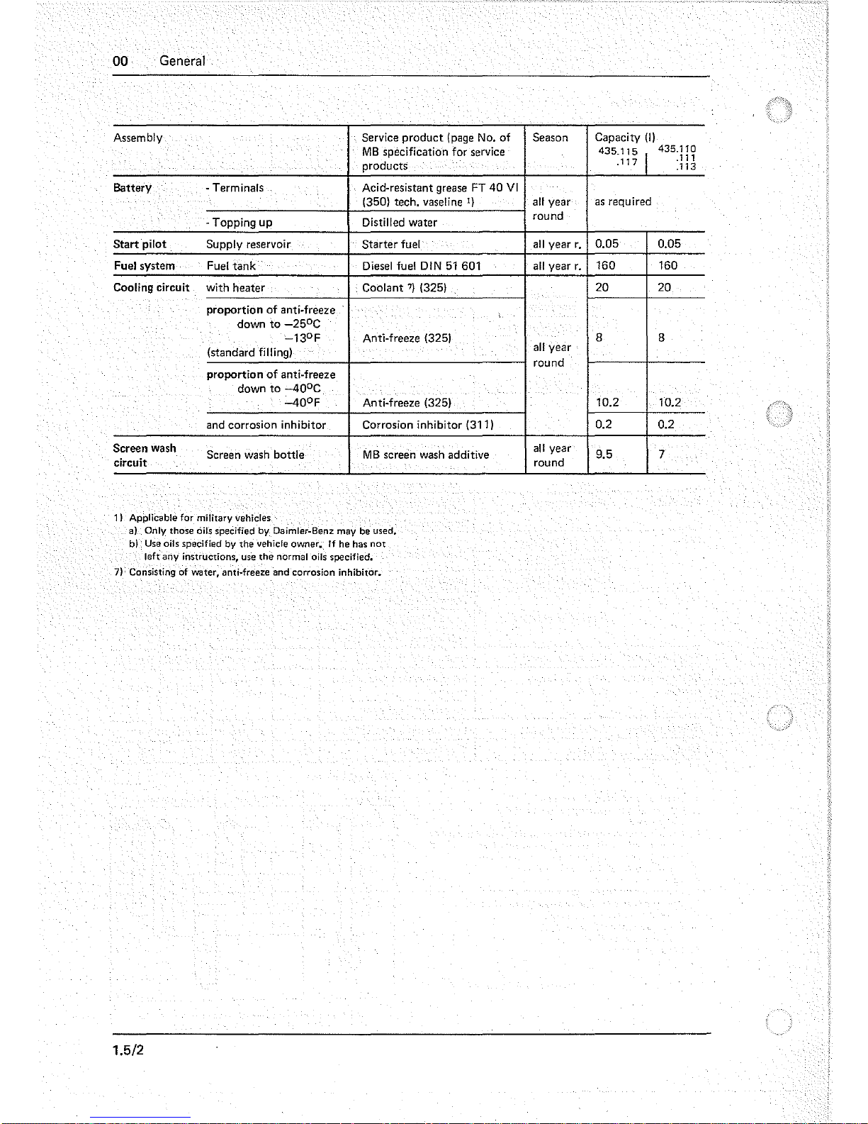
00
General
Assembly
Service
product
(page No.
of
MB
specification for service
products
Battery
- Terminals
Acid-resistant grease FT
40
VI
(350) tech. vaseline
1)
-Topping
up
Distilled water
Start
pilot Supply reservoir
Starter
fuel
Fuel system
Fuel
tank
Diesel fuel
DIN
51
601
Cooling circuit
with heater
Coolant
7)
(325)
proportion
of
anti-freeze
down
to
-25
0
C
-13
0
F Anti-freeze (325)
(standard filling)
proportion
of
anti-freeze
down
to
-40
0
C
-40
0
F
Anti-freeze (325)
and corrosion inhibitor
Corrosion inhibitor (311)
Screen wash
Screen wash bottle
MB
screen wash additive
circuit
11
Applicable for military vehicles
a)
Only those
oils
specified
by
Oaimler-Benz may
be
used.
b)
Use oils specified by the vehicle owner.
If
he has
not
left any instructions, use the normal oils specified.
7) Consisting of water, anti-freeze and'corrosion inhibitor.
1.5/2
Season
Capacity
(I)
435.115
I
435.110
.111
.117
.113
all
year
as
required
round
all
year
r.
0.05 0.05
all
year
r.
160 160
20 20
8
8
all
year
round
10.2 10.2
0.2 0.2
all
year
9.5 7
round
General
00
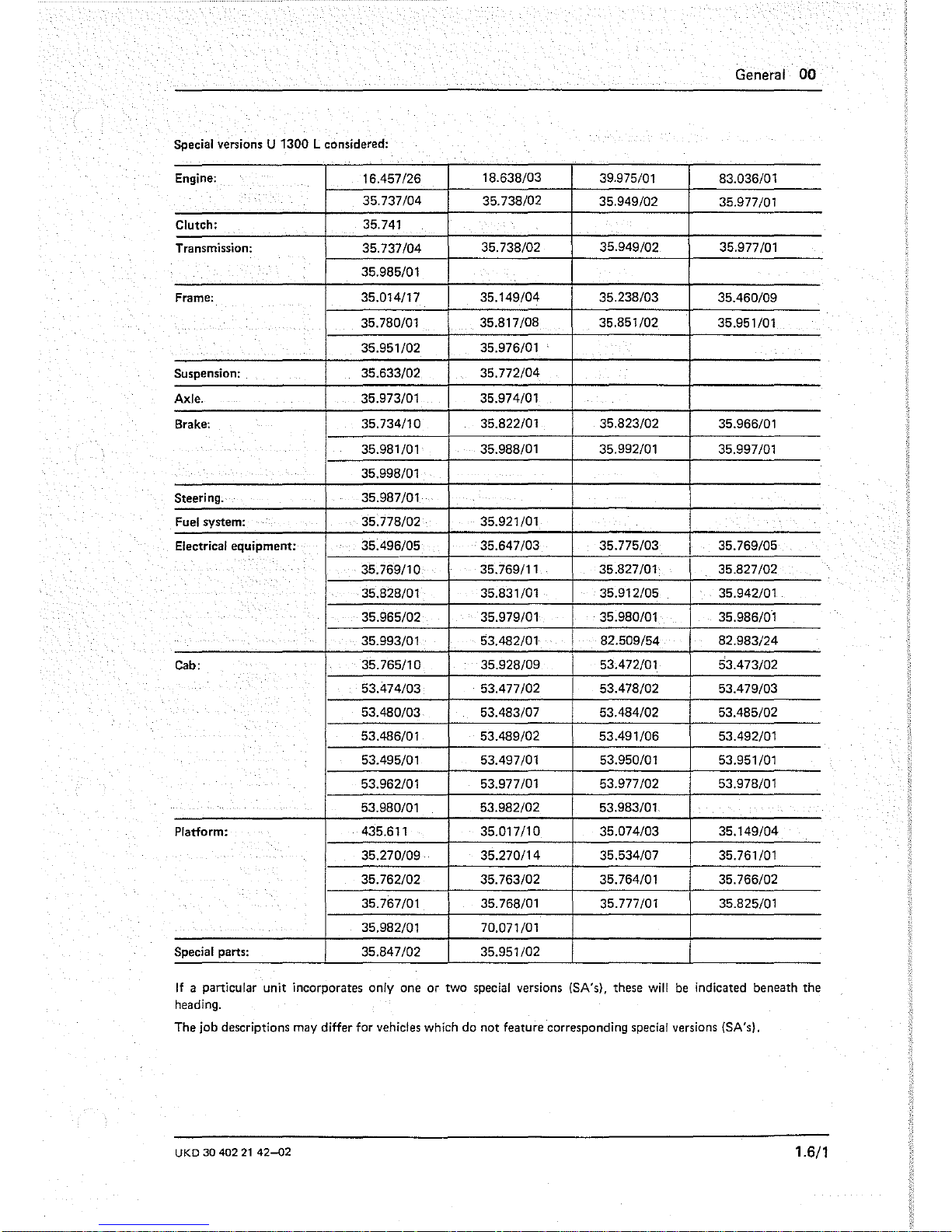
Special versions U 1300 L considered:
Engine:
16.457/26
18.638/03
39.975/01
83.036/01
35.737/04 35.738/02
35.949/02
35.977/01
Clutch: 35.741
Transmission:
35.737/04
35.738/02
35.949/02
35.977/01
35.985/01
Frame:
35.014117
35.149/04 35.238/03
35.460/09
35.780/01
35.817/08 35.851/02
35.951/01
35.951/02 35.976/01
'
Suspension: 35.633/02 35.772/04
Axle.
35.973/01
35.974/01
Brake: 35.734/10
35.822/01 35.823/02
35.966/01
35.981/01
35.988/01 35.992/01
35.997/01
35.998/01
Steering. 35.987/01
Fuel system: 35.778/02
35.921/01
Electrical equipment: 35.496/05
35.647/03 35.775/03
I
35.769/05
35.769/10
35.769/11 35.827/01 35.827/02
35.828/01
35.831/01 35.912/05 35.942/01
35.965/02
35.979/01
35.980/01
35.986/01
35.993/01 53.482/01
82.509/54 82.983/24
Cab:
35.765/10 35.928/09
53.472/01
53.473/02
53.474/03 53.477/02 53.478/02
53.479/03
53.480/03
53.483/07 53.484/02 53.485/02
53.486/01 53.489/02
53.491/06 53.492/01
53.495/01 53.497/01
53.950/01 53.951/01
53.962/01
53.977/01 53.977/02 53.978/01
53.980/01 53.982/02 53.983/01
Platform:
435.611
35.017/10
35.074/03
35.149/04
35.270/09 35.270/14 35.534/07
35.761/01
35.762/02 35.763/02
35.764/01
35.766/02
35.767/01 35.768/01 35.777/01 35.825/01
35.982/01
70.071/01
Special
parts:
35.847/02
I
35.951/02
If
a particular unit incorporates only one or two special versions (SA's), these
will
be
indicated beneath the
heading.
The job descriptions may differ for vehicles which do not feature corresponding special versions
(SA's),
UKD
30 402
21
42-02
1.6/1
00 General
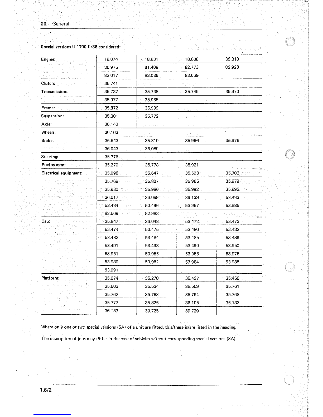
Special versions U 1700 L/38 considered:
Engine:
16.074 18.631
18.638 35.810
35.975 81.408 82.773
82.928
83.017 83.036 83.069
Clutch:
35.741
Transmission:
35.737 35.738
35.749 35.970
35.977
35.985
Frame:
35.872 35.999
Suspension:
35.301 35.772
,
Axle:
36.140
Wheels:
36.103
Brake:
35.643 35.810 35.966 35.976
36.043 36.089
Steering:
35.776
Fuel system:
35.270 35.778 35.921
Electrical equipment:
35.098 35.647 35.693 35.703
35.769 35.827 35.965
35.979
35.980 35.986 35.992
35.993
36.017 36.089 36.139 53.482
53.484
53.496 53.957 53.985
.
82.509 82.983
Cab:
35.847 36.048 53.472 53.473
53.474 53.475
53.480
53.482
53.483 53.484 53.485 53.489
53.491
53.493 53.499 53.950
53.951 53.955 53.958 53.978
53.980 53.982
53.984
53.985
53.991
Platform:
35.074
35.270 35.437 35.460
35.503
35.534 35.559 35.761
35.762 35.763 35.764 35.768
35.777 35.825 36.105 36.133
36.137
39.725 39.729
Where only one or two special versions
(SA)
of
a unit are fitted, thislthese is/are listed
in
the heading.
The description of jobs may differ
in
the case of vehicles without corresponding special versions (SA).
1.6/2
(
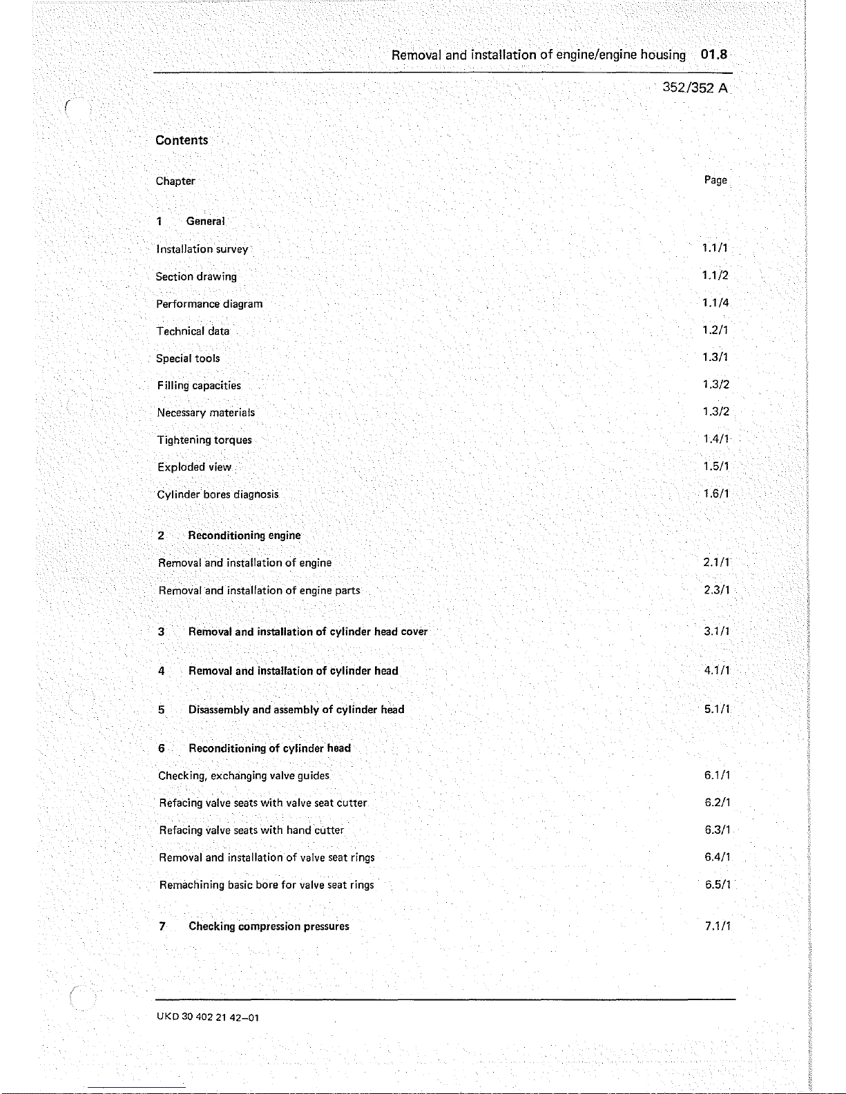
Removal and installation
of
engine/engine housing 01.8
Contents
Chapter
1 General
Installation survey
Section drawing
Performance diagram
Technical data
Special tools
Filling capacities
Necessary materials
Tightening torques
Exploded view
Cylinder bores diagnosis
2 Reconditioning engine
Removal
and
installation
of
engine
Removal
and
installation
of
engine parts
3
Removal
and
installation
of
cylinder head cover
4
Removal
and
installation
of
cylinder head
5
Disassembly
and
assembly
of
cylinder head
6 Reconditioning
of
cylinder head
Checking. exchanging valve guides
Refacing valve seats with valve seat
cutter
Refacing valve seats with hand
cutter
Removal and installation
of
valve seat rings
Remachining basic bore
for
valve seat rings
7
Checking compression pressures
UKD
30
402
21
42-01
352/352
A
Page
1.1
/1
1.1/2
1.1/4
1.2/1
1.3/1
1.3/2
1.3/2
1.4/1
1.5/1
1.6/1
2.111
2.3/1
3.1/1
4.111
5.1/1
6.1/1
6.2/1
6.3/1
6.4/1
6.5/1
7.1/1


General
01.8
352/352 A
Installation
Survey
Chassis Engine
Model
Sales
Series
Model Sales Series/SA
designation
Chassis end No.
designation
Engine end No.
435.110 U 1700
Irom 002 230
Series from 577 967
.111
U 1700
L"
from
000 008
353.959 352 A V/2
Series from 413 968
.113
U 1700 U38 from 084 642 352
A.
LI1t1" Series from 693 577
.115
U 1300
L"
from 000 019
352.X/2
Series from 482 095
353.961
352J(fl"
SA
16 457/26"
SA 35
975"
from 000
061"
"
SA
83
036"
from 509 465
---
from
PS"
353.959 352 A V/2
SA
36
019"
,
352
ALll/l"
from
PBJ)
.117 U 1300 U37
from
PBJJ
353.961 352.Xl2
Series
from
PBJJ
from
071
796
353.959
352 A V/2
SA
36
019"
352 A
L11/1"
from
627 976
.160 Attachment TM 170 from
PS"
353.959 352
ALlltl
from
PBJ)
.170 Attachment Condor from
PS"
353.977 352
AV/2
Series from 575 178
'--
1) L = Truck
2)
Special vehicle SW
3)
PS
= Start of production
4)
Valid only for fire service vehicles
5)
From engine end No.
691
150
UKD
30 402
21
42·03
1.1/1

01.8 General
352/352 A
General View
Engine 353.961
Engine 353.959
1.1/2

General 01.8
352 A
General view
UROI-0191
Engine 353.977
UKD
30
402
21
42-02
1.1/3

01.8 General
352/352 A
Performance diagram
Engine 353.961
P
[KW]
140
-_.-
--l"··"·¥
_.-
.
1-
1
---[--
-I
--
1-1-
I
r-1--i-;
I i
r
-'--
I,
i
IT
.
I ,
i/
120
100
80
60
40
f-
V
,
20
1--
i
I
o
--
---
-
~-
1---
L_
I
--r--
I
I
1200
p
--
f-~
,
;
-
....
,
f
---
-
I
./
p
/
/
V
r--....
I
'm
-
---
2000
2800
9
6
kW
[DIN)
'-
l
I-
M
Nm]
500
460
420
380
340
300
~
>-
L
-
t
[KW]
r--,---,----r-----r--.,--,---,--,
1401--+-+--I--+---+_J-1--
r--
---1---
---
i--I---+-,,+p-l
~4
kW
[DIN]
120
~t
___
--~-~_
~:~
____
1_-/1-"
______
+
__
100
-I----J/~+--+___l
/---
--l---r
-lI'--t---+--l--j
80--'-7
----
f----
1
-t-1I
-~-+i--l
60
I M
!
I;
[Nm]
401--I---+-L-,--+--+--I-----i--
r500
i i
i--t---i--~ii,/
A~t-.Ji"-..c---f--
~460
20
~
420
I
/i
i M
I--+----f-L+_
380
I,
+'
I
o
f----r--+-+----'-:
--1---1
340
I--+----i---I---t--+--+
I L
300
I I i I
-+'-+--1
I 1 i i - i
.~
o
400
n[l/minJ
I g
1200
2000
2800
Engine 353.957
to
engine end No.
691
149
_977
1.1/4

Performance Diagram
P
[kW]
140
120
100
80
60
40
20
o
o
400
n~/min]
1
Engine 353.959
from
engine end No. 691 150
UKD
30
402
21
42-02
J
I
I
I
•
/
I
I
I
1200
-
P
/
,I
1/
~
.........
"
M
1
.
2000
2800
.
p
12
4kW(DIN)
Q
-
M
Nm]
580
-
-
-
-
-
-
-
-
-
540
500
460
420
380
340
300
General 01.8
352/352 A
1.1/5


General
01.8
3521352
A
Technical
Data
Mercedes
Benz
type
352 352 A
Model
353.961
353.959
I
353.977
Combustion
system
Four-stroke
diesel
with
direct
Four-stroke
diesel
with
direct
injection
injection
Number
of
cylinders Cylinder arrangement
6,
vertical
in-line
Bore
0
mm
97
Stroke
mm
128
Total
displacement
cm
3
5657
Compression
ratio
17
16
Compression
bar
22
up
to
24
min.
20
at
starting
speed
Continuous
output
kW
(HP)
96 (130) 124 (168)
at
nominal
speed
l/min
2800 2800
-
Maximum
torque
Nm
363
491
1
)
I
5302'1
I
491
at
speed
l/min 1700 1600 1600 1600
Idle
speed
l/min
700
Start
of
delivery
before
TDC
0
18
21
1
)
I
19
2
)
I
21
Injection
sequence
1-5-3-6-2-4
Valve
ciearance,
cold
Inlet
mm
0,20
I
0,25" I
0,20
Exhaust
mm
0,30
I
0,40" I
0,30
Opening
pressure
new
bar
200 + 10
of
injection nozzles
used
bar
min.
180
Operating
temperature
'C
95
Oil
pressure
normal
bar
2
to
5
at
idle
speed
bar
min.
0.6
Weight,
dry
kg
460
480
1)
To
end
engine
No.
691
149.
2)
From
end
engine
No.
691
150.
UKD
30
402
21
42 - 04
1.2/1

01.8 General
352/352 A
Crankcase
Engine Type 352
I 352 A
b
Overall height of crankcase
359,10
a
mm
(Production size)
.
359,00
Repair stage I "
mm
358,80
358,70
a
Repair stage
11
'I
mm
358,50
358,40
Repair stage
III
'I
mm
358,20
358,10
Permissible
Crosswise
b 0,017
mm
unevenness
UZOI
- 0021
of mating surface
Lengthwise
e mm 0,03
e
Peak-ta-valley height
mm
0,008
up
to
0,016
of upper mating surface
Permissible parallel misalignment
of upper
to
lower mating surface
d mm
0,1
in lengthwise direction
Pressure test
in
water
bar
2,5
Piston may recede
= -
mm 0,07
Piston
may project
=+
mm
0,30
1) If mating surface
is
remachined to next repair stage, pistons of reduced compression height must
be
installed.
Cylinder Bores
(e)
Normal
Normal
I Normal
11
Repair
Repair
Repair
stage
I
stage
11
stage
III
mm mm mm
mm
mm mm
97,010
97,085 97,135
97,510
" 98,010 "
98,510
'I
96,990 97,065
97,115
97,490 97,990 98,490
97,010
21
-
-
97,0102)
96,990 96,990
Permissible ovality
mm
0.01
Permissible conicity
mm
0,01
Permissible deviation of
c~linder
bores
perpendicular to cranksha t axis, relative to
200 mm length
mm
0,04
Peak-ta-valley
height of the cylinder bores
mm
0,003 up to 0,005
Waviness of cylinder bores
mm
max.
50% of peak-ta-valley height
at top reversal point
mm
max.0,12
Wear
in
liner
of 1 st piston ring
in centre of
liner
mm
max.0.05
Bore depth for machining to the repair stages
mm
min.
250
1) Not engine 353.9591 977.
2)
Possible repair- crankcase with dry cylinder liners may be installed. If necessary, the scope of work
can
be requested.
Camshaft
Bearings
Basic
bores
in
crankcase
1.2/2
60,030
60,000
General
01.8
352/352 A
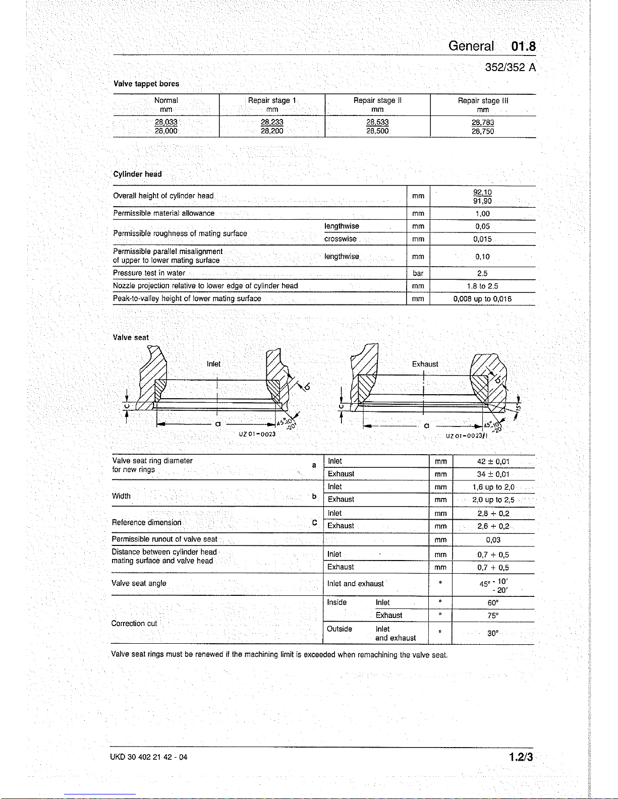
Valve
tappet bores
Normal
Repair
stage
1
Repair
stage
11
Repair
stage
III
mm
mm
mm
mm
28,033 28,233 28,533
28,783
28,000 28,200 28,500
28,750
Cylinder
head
Overall
height
of
cylinder
head
mm
92,10
91,90
Permissible
material
allowance
mm
1,00
lengthwise
mm
0,05
Permissible
roughness
of
mating
surface
crosswise
mm
0,015
Permissible
parallel misalignment
lengthwise
mm
0,10
of
upper
to
lower
mating
surface
Pressure
test
in
water
bar
2.5
Nozzle
projection
relative
to
lower
edge
of cylinder
head
mm
1.8
to
2.5
Peak-to·
valley
height of
lower
mating
surface
mm
0,008
up
to
0,016
Valve sea!
Exhaust
~--------a ------~~
l---
a
Valve
seat
ring
diameter
a
Inlet
mm
42 ± 0,01
for
new
rings
Exhaust
mm
34+
0,01
Inlet
mm
1,6
up
to
2,0
Width
b
Exhaust
mm
2,0
up
to
2,5
Inlet
mm
2,8 + 0,2
Reference
dimension
C
Exhaust
mm
2,6 + 0,2
Permissible
runout
01
valve
seat
mm
0,03
Distance
between
cylinder
head
Inlet
mm
0,7 + 0,5
mating
surface
and
valve
head
Exhaust
0,7 + 0,5
mm
Valve
seat
angle
Inlet
and
exhaust
·
45.-
10
'
-
20'
Inside
Inlet
·
60·
Exhaus!
·
75·
Correction
cut
Outside
Inlet
·
30·
and
exhaust
Valve
seat
rings
must
be
renewed
il
the
machining
limit
is
exceeded
when
remachining
the
valve
seat.
UKD
30 402
21
42 - 04
1.2/3

01.8
General
352/352 A
Valve Seat
Rings
Cl
i=ffi
A
B
UZ01-0019
Exhaust A Inlet B
I 1)
1)
Outside diameter
Normal
mm
38,080 45,080 45,880
valve
seat ring c and d 38,070
45,070
45,870
Repair stage I mm
38,380
45,380
46,180
38,370
45,370
46,170
Repair stage
11
mm
38,580 I
-
45,580
-
38,570
45,570
Bore
diameter
Normal
mm
38,025 45,025 45,825
in
cylinder head c 1 38,000
45,000
45,800
and d 1
Repair stage
I
mm
38,325 45,325 46,125
38,300
45,300
46,100
Repair stage
11
mm
38.525 I
-
45,525
-
38,500 45,500
Installation
depth in cylinder head
e mm
11,20
11,10
Distance between cylinder head face and
b 1 mm
2,6 + 0,2 2,8 + 0,2
valve
seat ring
Basic bore in
cylinder head
mm
38,000 + 0,025 45,000 + 0,025
Height of valve seat rings
a mm 8,5 -
0,1
8,3 -
0,1
Valve seat ring overlap in cylinder head
mm 0,045
to
0,080
Valve
Guides
Dislance between
valve guide
Exhaust inlet
vaive spring seat
a mm
24 -
0,5
mm
10,022 9,022
10,000
9,000
,
Inside diameter
Length
mm 73
78
~
Normal Repair Repair Repair
stage
I stage
11
stage
III
mm mm mm mm
Outside diameter
15.046 15,146 15.246 15,546
15,028
15,128
15,228 15,528
Bore
in
cylinder head
15.018 15,118 15,218 15,518
15,000
15,100
15,200
15,500
Overlap
mm + 0,010
to
+ 0,046
1)
Engine model 353.959 from engine end No. 549 882.
1.2/4

General 01.8
352/352 A
Special
Tools
Cons.
Tool
Tool No.
Tool
Set
No.
1
Ring wrench for injeclion lines
000 589 07 03 00 A
2
Pliers for connecting nipple of rocker shafts
312589013700
A
3
Claw wrench for protective sleeve
in
cylinder head
346 589
00 07 00
B
4
30 mm socket for pressure screw
in
nozzle holder
000 589 75 09 00
B
5
Extractor for nozzle holder
352 589
00 33 00
B
.
6
Centering drift
425 589
00
61
00 B
7
Drift for removing inlet valve guide
110589021500
C
8
Drift for removing exhaust valve guide
615589011500
C
9
Fitting drift for valve seat rings
346589031500
C
10
Inslaller for valve guide 352 589 00 43 00 C
11
Reamer, 9 mm
diameter
for
inlet
valve
guide
000589105300
C
12 Reamer,
10 mm diameter for exhaust valve
gUide
000 589
11
53 00
C
13
Reamer for valve guide sleever bore in cylinder head
000589
185300
C
14 Hand cutter for valve seal rings
000589126600
C
15
Special wrench to retighlen injeclion lines 000 589 68 03
00
D
16 Limit plug gauge dia. 9 mm inlet valve guide
116589082100
D
17
Connection piece for compression test 352 589
00
21
00 D
18
Limit plug gauge,
10 mm dia. for exhaust valve guide
617589052300
D
19 Handle for cylinder head
(2
necessary)
31258901
31
00
D
20
Rud
special lifling chane 435 589 00 62 00 D
. -
UKD
30 402
21
42·03
1.3/1

01.8 General
352/352
A'
Capacities
Assembly
Engine
With
oil
filler
Proportion
in
oil filter
Cooling system With heater
Antifreeze proportion
(Standart
filling)
Antifreeze proportion
And
corrosion
protection
1)
Viscosity grades
Outdoor temperature
Single grade oil
°rS6
°C
+30
-----
+68
+20
+50
+10
+32
0
+23
- 5
+14
-10
00
NM
I I
33
"''''
max.
--:--
mm.
down to - 25°C
-13°F
down
to
-40°C
o
'"
I
3
o 0
M
, 0
3 ..
o I
3
o
-40°F
o
'"
I
3
o
N
UZD-D061!1
')
SAE 40 may be used if outdoor temperatures are permanently above
+ 30°C (86°C F).
21
To engine end No. 502 247
3 From engine end
No.
502 248
4
Consisting
of
water,
antifreeze
and
anticorrosion
oil
5 For supercharged engines, onty use engine oil of "S
3"
quality.
Necessary material
Cons.
Designation
No.
1 Loctite
Nr.
241
2 Loctite Nr. 573
3 Curil T
4
Curil K 2
5 Loctite
Nr.
221
1,3/2
Service product (page
No.
SAE- Capacities
(I)
of MB service product grade
352~
specification)
352"
352A
Engine
oil
1)
14,5
15,0
(224,226)
11,5 12,0
(227.0,
227.1)"
1,5
2 x
1,0
Coolant"
(325)
20
Antifreeze (325) 8
Antifreeze (325)
10,2
Anticorrosion oil (311)
0,2
Part
No.
002989
70
71
001
9894520
001
9893720
commercially
available
002989
69
71

General 01.8
352/352 A
Tightening
Torques
Designation
Thread
Nm
Torquing angle
Cylinder
head cover
MS
25
'Push rod cover to crankcase
MS
4 to 6
Timing
gear
case
cover
Casting
M6
8
Sheetmetal
M6
8
Cylinder head (tightened
in
3 stages according
to
tightening diagram)
~,ruru"
M 12
60
2nd step
M 12
90
2lt>"
3rd
step
M 12 110
Oil pan (sheet steel)
M6
8
M8
9
Oil
drain plug to oil pan M
26
80 + 10
Protective sleeve for nozzle holder in cylinder head M 14 60
Nozzle holder
in
cylinder head, thrust screw M
34
60
to
70
Tapered plug
in
cylinder head
M
30 100
to
200
M
24
70
to
150
Coolant line on top of cylinder head
M8
25
Flywheel housing to crankcase M 12 80
Timing gear case to crankcase
M
10
65
Screw
plug for oil passage
in
crankcase M 20 100 ± 10
Screw plug for oil duct, front and rear
MI6
40 + 5
Flywheel to crankshaft Initial torque M 12
30 + 10
Final
torque M 12
-
90·+
20·
Rocker arm brackets assembly to cylinder head M 12 100
up
to
110
Leakage
fuel line to injection nozzle
MS
15upt020
Union nut of injection line to injection pump M 12 25
to
nozzle holder M 14
25
Air compressor bracket to engine mount
75
Exhaust manifold
to
cylinder head M 10
30
Exhaust manifold to cylinder head, 2-hole metal plate M 10
25
Flanged manifold to exhaust pipe M 10
45
Front engine mounting to frame M 14 140
±,20
Rear engine mounting to frame M 14 140
±,20
Front engine support to crankcase M 14 170
±,20
Left engine support arm to flywheel housing
M 12 110
±,20
UKD 30 402
21
42 - 04
1.4/1


Exploded view
~201
@Il20S
2;4
~
237
Ql240
@244
Engine housing
15
Crankcase
18
Screw plug
21
Sealing ring
23
Screw plug
25 Sleeve
27
Sleeve
30
Straight pin
33
Sealing ring
36
Screw plug
45
Sealing ring
45
Screw plug
480
Sealing ring
48E
Screw plug
49C
Sealing ring
490
Screw plug
56
Straight pin
61
Straight pin
62
Fabric sealing ring
67
Bolt
70
Cover
72
Gasket
89
Guide
tube
UKD
30
402
21
42-{)1
49D@
49C<£;I
El"
~'57
~
"",154
131
~151
@
e--@~1J3
95E Screw plug
95F
Sealing ring
97
Camshaft beari
ng
No. 1
100
Camshaft bearing Nos.
2.3,4
118
Guide
tube
121 Cap
nut
130
Bracket
133
Flange
137
Bolt
140
Gasket
145 Oil dipstick
148
Sealing ring
151
Flange
154
Sealing ring
157 Union
160
Gasket
164 Timing gear case
167
Straight pin
170
Straight pin
176
Lock washer
179 Bolt
183
Bolt
186
190
193
196
197
201
205
208
211
214
221
224
227
231
237
240
244
260
274
280
284
General 01.8
6121
352/352 A
N
::>
Timing gear case cover
Gasket
Shaft
seal
Lock washer
Bolt
Spacing ring
Bolt
Pointer
Gasket
Cover
Push rod cover
Gasket
Sealing ring
Bolt
Oil pan
Sealing ring
Screw
plug
Repair
set
Bolt
Washer
Bolt
1.5/1

01.8 General
352
Exploded view
,\~61
@62
Cylinder head
61
Engine breather filter
320
Valve seat ring
62
Nut
325
Sealing ring
287
Cylinder head
328
Protective bushing
290
Screw plug
330
Cylinder head gasket
296
Stopper
332
Gasket set
299
Screw plug
337
Cylinder head cover
303
I ntake valve guide
339
End cover
308
Exhaust valve guide 342 Sealing ring
1.5/2

Cylinder bore diagnosis
Owner
2.
Branch/agents
5. Place
6.
Registration
No.
7.
Date
of
1st registration
8, Model
11.
Copy
12.
Presented
by
13. Time accepted
14.
Accepted
by
Piston skirt has seized. Honing
pattern
destroyed.
Engine has
to
be
removed.
3.
Date
9.
Chassis No.
15.
Engine
No.
Mercedes-Benz
service
4.
Repair
job
No.
10.
Mileage
16.
Provisional deadline
R'308S
Cy!.
1-3
Cy!.4
Cy!.
5-6
Piston
skirt
and
oil scraper ring have seized. Honing
pattern
destroyed.
Engine has
to
be
removed.
Piston skirt cracked. Honing pattern still complete. Engine can continue working.
Ring has seized
at
land side, approx.
30
mm
wide.
Step
due
to
oil ring
is
quite
evident.
Honing
pattern
destroyed. Engine
has
to
be
removed.
Oil
ring seiZure
has
extended across entire
cylinder
half. Honing pattern destroyed.
Engine
has to be removed.
Semi-severe oil ring seizure. Honing pattern
is
still quite evident. Engine can continue
working.
Diagnosis
chart
OF
650
09
057
00
a -
167
- Daimler·Benz
AG.
Stuttgart·Unterturkheim.
Zentralkundendienst
1.6/1

01.8 Cylinder bore diagnosis
352/352 A .
~
~
~
Z
1
----I-
1
1
1
-+-
-+-
1
I.
1
I
-+-
+-
I
I
I
I
--j-
-+-
1 1
1
1
-+-
+-
I
I
I I
-+-
-t-
1
1
I
1
-j-.
--l-
I
I
I
1
--j-
-t-
I I
I
I
---t-
---t-
1
I
I
1
-+-
-+-
1
1
I
I
.
--+-
-1-
.
I
I
I
I
I
I
-+-
-+-
I
I
[]
w
([]
" "
_w
rn~
o
~
i:i
"Vi
Ir-
eO
r-I
r-
.-
e
r-
0c>
0 b
~rn
::::>!
0
4::0
1.6/2 Diagnosis chart OF
650
09
057
00
a -
167
- Daimler·Benz AG, Stuttgart-Unterrurkheim, Zentralkundendienst

Removal
and
Installation of Engine 01.8
Removal
Note:
Engine removal is similar for both engines
No.
353.959 and 353.961.
1 Raise driver's cab, see 60.5-2.1/1 or
60.5-2.211.
2 Disconnect battery.
Note:
Firstly disconnect
(-)
then (+) terminal.
3 Drain coolant.
4 Remove V-belt from intermediate fan shaft.
5 Detach exhaust pipe from exhaust manifold.
Note:
For engine model 353.959, detach exhaust pipe
at
turbocharger.
UKD 30 402
21
42-03
352/352
A
©
www.buchundbild.de
2.1/1

01.8
Removal
and
Installation
of
Engine
352/352
A·
2.1/2
6 Disconnect electrical lines and ground strap from
starter.
7 Mark
and
detach alternator wiring harness at oil coo-
ler
and
electrical lines at the alternator.
8 Detach electrical
line at oil pressure pickup and coo-
lant temperature pickup.
9 Remove fuel intake
line
(1)
and return lines (2).
Note:
The bleeding facility
on
the fuel filter is no longer
fitted from chassis end No.
086 284.
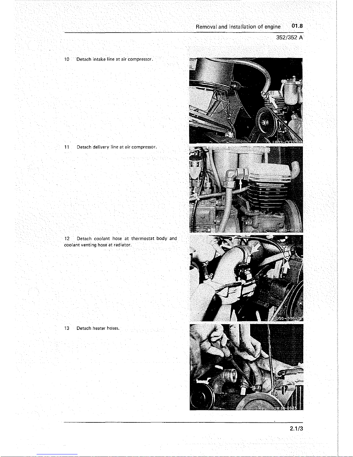
Removal and installation of engine 01.8
352/352 A
10 Detach intake line
at
air compressor.
11
Detach delivery line
at
air compressor.
12 Detach
coolant hose
at
thermostat body and
coolant venting
hose
at radiator.
13 Detach heater hoses.
2.1/3

01.8 Removal
and
installation
of
engine
352/352 A
14
Detach
coolant
pipe
at
coolant
pump
and re·
servoir.
15 Detach venting line between timing gear case
end steering fluid reservoir.
16 Detach
hydraulic
pump
and
bracket
from en·
gine support. Do
not
remove lines.
17 Detach propeller shaft from
input
flange.
2.1/4

Removal
and
Installation
of
Engine
01.8
18
Remove clutch slave cylinder, do not detach line.
19
Detach starter wiring harness and venting line from
clutch housing.
Also remove fuel line, leakage oil line, cold
starting line and control cable for idling if SA 35 989 installed.
20 Remove fastening bolts for rear engine mounts.
21
Remove fastening bolt at front engine mount. Detach
cover.
UKD 30 402
21
42-03
352/352
A
2.1/5

01.8
Removal
and
Installation
of
Engine
352/352
A
2.1/6
22 Detach engine breather filter.
Note: Renew engine breather filter without the code
marking
"E" every two years. A damaged engine breat-
her filter must always
be
renewed immediately.
23 Drain engine oil
as
required.
24
Lift
out engine using special tool No. 19.
25 Clean all parts, check and replace if necessary.
Installation
Note:
Engine installation is similar for both engine
models
No.
353.959 and 353.961.
1 Slide engine into position using special tool No. 19.
2 Fit cover and fastening bolt to front engine mount and
tighten boil.
Tightening torques, see
1.4/1.

3 Locate and tighten fastening bolts
of
rear en-
gine
rtlOunts.
See 1.4/1 for tightening torque.
4 Lower engine and remove special
tool No. 19.
Attach engine breather filter with sealant
No.
2.
5 Remove starter wiring
loom and venting line
from clutch housing. Also remove fuel line, leak-off
line, cold start line and idling control cable
as
fitted
to
special version
35
989.
Adjust idling setting, see
30.4·2.1/1.
6 Attach clutch slave cylinder after coating sealing surface with
seal
ant No. 2.
7 Attach propeller shaft
to
input flange.
UKD
30 402
21
42-01
Removal
and
installation
of
engine
01.8
352/352 A
2.117

01.8 Removal
and
installation
of
engine
. ,
352/352 A
2.1/8
8 Attach hydraulic pump and bracket to engine
support.
9 Attach venting
line to timing gear case.
10 Attach coolant pipe
to
coolant pump and re'
servoir.
11
Attach electric line to coolant temperature pick-
up.

Removal
and
Installation
of
Engine 01.8
12
Connect
heater
hose.
13
Attach
coolant
hose
to
thermostat
housing
and
coolant
venting
hose
to
radiator.
14
Connect
delivery
line
to
compressor.
15
Attach
intake
line
to
compressor.
UKD 30 402
21
42·03
352/352
A
2.1/9

01.8
Removal
and
Installation
of
Engine
352/352
A
2.1/10
16 Attach fuel intake (1) and return lines (2).
Note:
The vent on the fuel filter is no longer fitted from
chassis end
No.
086 284.
17 Connect electrical line to oil pressure pickup.
18 Referring to marks, attach electrical lines to genera-
tor and wiring harness
to
oil cooler.
19 Attach electrical lines and ground strap to starter.

20 Attach exhaust pipe
to
exhaust manifold.
See
1.4/1 for tightening torque.
Note:
For engine model 353.959, attach exhaust pipe
to
turbocharger.
21
Attach V-belt for intermediate fan shaft.
22
Connect battery.
23
Lower cab,
referring
to
60.5-2.1/1
or
60.5-2.2/1.
24 Fill with engine oil
as
required.
See
1.3/2 for quantity.
25
Vent fuel system, referring
to
07.8-6.1/1.
26 Fill with coolant. Check cooling system for
leakage, referring
to
20.8-5.1/1.
See 1.3/2 for quantity.
Note: The reservoir ought
to
be
2 thirds full.
27
Carry
out
trial run.
UKD
30
40221
42-01
Removal
and
installation
of
engine 01.8
352/352 A
2.1/11


Removal and installation of engine
parts
01.8
352/352 A
Removal
Remove engine, referring
to
2.1/1.
2 Drain coolant
at
crankcase.
3 Detach clutch casing and input shaft.
4 Detach and remove clutch.
5 Detach flywheel.
2.2/1

01.8
Removal
and
installation of
engine
parts
352/352 A,
6 Detach flywheel housing.
7 Unscrew air compressor
at
bracket.
8 Detach air compressor
lube lines and front en-
gine support.
9 Detach generator.
2.2/2

Removal
and
installation
of
engine, parts 01.8
10 Attach assembling fixture
to
rear
~nd
of crank-
case.
11
Attach assembling fixture to front end of crank-
case, Position engine
in
trestle.
12
Detach coolant reservoir.
Installation
Attach and tighten coolant reservoir.
2 Attach engine to special tool No. 19 and re'
move assembling fixture at front and rear.
3 Attach generator.
4 Attach and tighten front engine support,
referring
to
1.4/1.
UKO
30
402
21
42-01
352/352 A
2.2/3

01.8
Removal
and
installation
of
engine
parts
352/352 A
2.2/4
5 Attach lube lines to air compressor and air corn·
pressor
to
bracket. Tighten with reference
to
1.4/1
for tightening torque.
6
Coat flywheel housing with sealant No. 3 apply
sealant No. 4
to
bolts and then tighten.
See
1.411
for tightening torque.
7 Attach and tighten flywheel, referring
to
1.411
for tightening torque.
8
Using
special tool
No.
6 attach and tighten
clutch.
See
25.10-1.4/1
for tightening torque.
9
Coat clutch housing with sealant No.
2,
apply
locking fluid No. 1
to
bolts and then tighten.
See
25.10-1.4/1
for tightening torque.
10
I nstall engine, referring
to
2.1/1.

Removal
and
Installation
of
Cylinder
Head
Cover
01.8
Removal
Note:
Removal
is
similar
for
both
engine
models
No.
353.959
and
353.961.
1
Unscrew
engine
hood
at
inside.
2
Unscrew
injection
line
at
cold
start
nozzle.
3
Detach
engine
hood
and
remove
intake
hose.
Note:
For
engine
model
353.959,
detach
connection
for
manifold
pressure
compensator
at
cylinder
head
cover.
intake
hose
at
engine
breather
filter
as
well
as
the
connection
to
the
turbocharger.
4
Unscrew
and
remove
cylinder
head
cover.
5
Clean
sealing
surface
on
cylinder
head
and
cylinder
head
cover.
6
Install
in
reverse
order,
using
new
gasket.
Tightening
torques,
see
1.4/1.
Note:
The
fastening
bolts
of
the
cylinder
head
cover
must
be
fully
screwed
in
so
that
the
head
of
the
bolt
makes
contact
with
the
cover
while
ensuring
that
the
bracket
for
the
coolant
equalization
tank
is
secured
with a long
bolt.
7
Start
engine
and
check
for
leaks.
UKD
30
402
21
42-03
352/352
A
3.1/1


Removal
Note:
Make
sure
that
engine
is
cold.
Removal
is
similar for both engine model No. 353.959
and
No.
353.961.
1 Prop up cab and clean upper parts of engine.
See
60.5-2.1/1,
or
60.5-2.2/1.
2 Detach intake pipe.
3 Drain coolant.
4 Detach coolant reservoir and bracket.
5 Detach heater hoses.
Removal
and
installation
of
cylinder
head
01.8
352/352 A
4.1/1

01.8
Removal
and
installation of cylinder
head
352/352 A
4.1/2
6 Using special tool No.14 , detach injection lines
at
injection pump.
7 Detach cold starting reservoir (1) and double
fuel filter (2).
8 Detach cold starting line, leak·off line and
bracket for fuel lines
at
cylinder head. Tie up
at
one
side.
9 Detach exhaust pipe from exhaust manifold.

Removal
and
installation
of
cylinder
head
01.8
352/352
A
10 Disconnect coolant temperature pickup and de-
tach coolant pipe at coolant thermostat body.
11
Remove cylinder head cover.
12 Remove bolts holding rocker arm brackets.
13 Remove rocker arm brackets with rocker
shafts, connecting nipples and rocker arms.
UKD
30
402
21
42-02
4.1/3

01.8 Removal and installation
of
cylinder
head
352/352 A
4.1/4
14 Carefully withdraw push rods.
Note:
To
avoid withdrawing the tappets from their
guides.
the
tappets must previously be loosened by a
short, sharp up and down movement
of
the
pushrods.
15 Undo
all
the cylinder head nuts
or
cylinder
head bolts
in
the reverse order
to
the tightening chart.
16 Remove studs.
Note: The studs and
cylinder head nuts fitted pre·
viously
were replaced
as
from engine end No. 678 155
by
cylinder head bolts which can be exchanged in
reverse.
17
Using
special tool No. 18, lift up cylinder head
and remove gasket.
Important!
Deposit cylinder head so
that
no damage
is
done
to
injection nozzles.

Removal and Installation of Cylinder Head 01.8
18 Clean cylinder head and crankcase parting surfaces
Important!
Blind holes
in
the crankcase
must
not
show
any
signs
of
dirt
or oil.
19
Check parting surfaces with straight edge.
See
table
on
page 1.2/3 for permissible uneveness.
Note: Distorted or damaged part;ng surfaces
should
be
refaced
to
the' necessary peak-.o-valley height.
See
table
on
page 1.2/2 and 1.2/3 for permissible peak-to-
valley height.
Installation
1 Position
new.
cylinder gasket
on
crankcase with lettering
facing upwards
2 Using
special tool
No.
18, position cylinder head
on
crankcase.
Note: For engine
model
No.
353.959, a modified cylinder
head marked with
"0"
has been installed from engine
end
No.
691
150. The modified cylinder head cannot
be
retrofit-
ted
on
previous models.
UKD 30 402
21
42·03
352/352
A
4.1/5

01.8 Removal and Installation of Cylinder Head
352/352
A
4.116
To
Engine End No. 678 154
3
Oil threads of stud bolts and screw in.
Important!
Do
not pour oil into the threaded holes.
4
Fit
cylinder head nuts and tighten referring
to
tighte-
ning diagram.
1
st
lightening stage
60
Nm
2nd lightening stage
90
Nm
3rd tightening stage 110
Nm
Note: Tighten cylinder head nuts
for
the
first
time
to
120
Nm at the
3rdtigthening
stage.
From Engine End No. 678 155
5
Oil
cylinder head bolts at the thread and at the head
contact surface and screw
in,
Important!
Do
not pour
oil
into the threaded holes.
Note:
Only cylinder head bolts are stocked
in
the spare
parts store. The cylinder head
bolts can
be
installed
in
engines with a lower engine end number.
6 Tighten cylinder head bolts according
to
tightening
diagram.
1
st
tightening stage 60
Nm
2nd lightening stage 90
Nm
3rd lightening stage 110
Nm
Note: Tighten cylinder head bolts
for
the
first
time to
120
Nm
at
the 3rd
lightening
stage.
7
Install push rods.
8 Attach rocker
arm
brackets together with rocker arm
shafts and rocker arms. Turn back valve adjusting screws
and
lighten rocker
arm
brackets.
Tightening torques see
1.4/1.

Removal and Installation of Cylinder Head 01.8
9 Using special tool No.
2,
install connecting nipple
and spring.
Note: Install the connecting nipple with the
small
inside
diameter in
the
direction
of
driving.
Ensure it is cor-
rectly
seated.
10 Adjust valve clearance, refer to 05.8 - 2.1/1.
11
Install cylinder head cover.
For tightening torques, see
1.411.
12 Attach coolant pipe, with new gasket on coolant
regulator housing, connect coolant temperature sensor
cable.
For tightening torques, see
1.4/1.
13 Attach exhaust pipe with gasket to exhaust manifold.
For tightening torques, see
1.4/1.
UKD
30 402
21
42 - 04
352/352 A
-:::::::c::;:._
t
--.J~
.":.;;;::..-._ ---rr----'-..,::;?J-_
-=:-r-
\I:....:.:...=:::,o._=::::'
__
...h
L
______
"";..._
. .l.i
UZ 05-002611
4.1/7

01.8
Removal
and
Installation
of
Cylinder
Head
352/352 A ;'
4.1/8
14
Attach
cold
starting
line,
leakage
fuel
line
and
brack-
ets
for
fuel
lines
to
cylinder
head.
15
Install
cold
start
reservoir
(1)
and
double
fuel
filter
(2).
16
Using
special
tool
No.
1,
connect
injection
lines
to
injection
pump
and
tighten
with
special
tool
No.
15.
For
tightening
torques,
see
1.4/1.
17
Attach
heater
hoses.

Removal and Installation of Cylinder Head 01.8
18
Attach
coolant equalization tank
with
bracket.
19
Attach
intake
pipe.
20
Lower
driver's
cab,
see
60.5-2.1/1
or
60.5-2.211.
21
Fill
with
coolant,
check
cooling
system
for
leaks.
For
capacities
see
1.3/2.
Note:
The
equalization tank
should
be
two-thirds fill.
Important!
Upon
completion
of the installation,
warm
up
engine,
loosen
each
nut
individually
in
sequence
shown
in
the
tightening
diagram
and
then
finally tighten
to
a torque of 110
Nm.
On
no
account
must
all
nuts
be
loosened
simultaneously
before
final
torque
is
applied.
Readjust
valve
clearance.
After
500
km,
retighten
the cylinder
head
nuts
and
readjust
the
valves.
UKD 30 402
21
42-03
352/352
A
4.1/9


Disassembly
Remove cylinder
head, see 4.1/1.
2 Lay cylinder head on a support.
Important!
The cylinder head must
not
rest
on
the injector
nozzles.
3 Remove exhaust manifold and coolant
rail
from
cylinder head.
4 Remove injector pipes from
injecto'" with
special tool No. 1.
5 Release injector pipes from cylinder head and
remove.
Do
not bend injector pipes.
6 Remove
leak·off pipes.
7 Remove thrust screw for nozzle holder with
special tool No. 4.
UKD
30
402
21
42-01
Disassembly
ana
assembly
of
cylinder head 01.8
352/352 A
5.1/1

01.8 Disassembly and assembly
of
cylinder head
352/352 A'
5.1/2
8 Remove nozzle holder with special tool No. 5.
9 Remove valves, see 05.8·2.2/1.
10 Remove protective sleeve with special tool
No.
3.
11
Clean
all
parts, check and change
if
necessary.
12 Check valve guides and change
if
necessary, see
6.1/1.
13 Check valve seats and reface
or
renew if nec·
essary. See 6.2/1 or 6.3/1.
14 Check injector nozzles,
see
07.8·4.2/1.
Assembly
Insert new sealing ring for the protective
sleeve
into cylinder head.
2 Insert protective sleeve and tighten with special
tool
No.
3.
Tightening torque, see
1.4/1.
3 Insert new sealing ring into the protective sleeve
4 Fit nozzle holder with nozzle into cylinder
head observing lock on the nozzle holder (1) and
groove
(2)
in
the cylinder head.
Important!
Do
not knock nozzle.

5 Fit valves, see 05.8-2.2/1.
6 Tighten thrust screw for injector nozzle with
special
tool No. 4.
Tightening torque, see
1.4/1.
7 Fit leak-off pipes with new sealing pieces.
Tightening torque, see
1.4/1.
Note: Fit locking bolt (24 mm) with sealant No. 5.
8 Fit
injector pipes, fit locking bolt (24 mm) with
sealant No.
5, renew rubber seals at
the
bushings and
tighten locking
bolt (17 mm).
9 Tighten without tensioning the injector pipes
using special
tool No. 15.
Tightening torque, see
1.4/1.
10 Fit exhaust manifold and coolant rail with new
gaskets.
Tightening torque, see
1.4/1.
11
Install cylinder head, referring
to
4.1/1.
UKD
30
40221
42-01
Disassembly and assembly
of
cylinder head 01.8
352/352 A
5.1/3


Checking
Disassemble cylinder head, referring
to
5.1/1.
2 Clean valve guide, removing carbon deposits
with
special tool No.
11
or No.
12,
3 Check bore using special tool No. 16 or No. 18.
Exchanging
Drive
out
valve guide using special tool No. 7
or
No. 8.
2
Clean and check basic bore
in
cyl inder head.
See 1.2/4 for table.
3 If "repair stage" valve guides are
to
be fitted,
ream basic bore
to
next higher repair stage, using spe·
cial tool
No.13.
See 1.2/4 for repair stages.
UKD
30
402
21
42-01
Checking, exchanging valve guides 01.8
352/352 A
6.1/1

01.8
Checking,
exchanging
valve guides
352/352
A'
6.1/2
4 Select valve guide so
that
overlap specification
is
met.
See table on page
1.2/4.
5 Heat cylinder head.
6
Coat
new valve guide with graphite oil and posi-
tion
in
cylinder head bore.
7
Slip spacing sleeve
of
special tool
No_
10 over
valve guide.
8 Knock valve guide into position,
using
special
tool No.
10.
9 Check valve guide for firm fit, either
by
knock-
ing
with
hammer
or
by applying
test
pressure. Loose
valve guides are
to
be
knocked
out
again
and
replaced
by
valve guides
of
larger outside diameter.
10 Ream inside diameter
of
valve guide, using spe-
cial
tool
No_
11
or
No. 12.
11
Check inside diameter
of
valve guide, using spe-
cial tool No. 16
or
No. 18.
12 Re-assemble cylinder head, referring
to
5.1/1.

Refacing valve seats with valve seat
cutter
01.8
Refacing
Disassemble cylinder head, referring
to
5.1/1.
2 Check
valve guides and exchange if necessary,
referring
to
6.1/1.
3
Clamp cylinder head in jig.
4 Check
valve seat.
Note:
If valve seats show only slight traces of wear,
they
can
be
refaced
without
necessitating
replace·
ment
of
valve
seat
rings, provided they
are
not
ma-
chined below their
bottom
limit.
See
1.2/4 for repair size.
5
Introduce pilot into valve guide so
that
stop
of
slotted rod rests
on
valve guide. If necessary, press
slotted
rod
~ownwards
using screwdriver, and tighten
pilot.
6 Fasten cutting tool
to
slide rest.
Note: Make sure
that
cutting tool
is
positioned cor·
rectly
on
slide rest. Release coupling
nut
to
stop free
slide rest. Attach crank handle to arm marked 45
0
•
7 Release coupling nut (2), slip
cutter
over pilot
and
turn
screw (1) until cutting tool
is
positioned
in
center of
valve
seat.
8 Press pilot support (1) downward
onlo
pilot,
and clamp with screw (2), making sure
that
knurled
ring
(3)
is
screwed down and locking screw (4)
is
tight
UKD
30 402
21
42-01
352/352 A
6.2/1

01.8 Refacing valve seats with valve seat
cutter
352/352 A
6.2/2
9 Turning hand crank. move steady bar
to
correct
position. Floating guide
is
to
be locked horizontally
in roughly
the
center of the guide with
the
aid
of
steady clamp. Cutter must
turn
just
as
smoothly
as
before.
10 Turning
the
quick-action adjuster sets cutting
tool to inner seat edge. Tighten coupling
nut
now,
but
do not start chip feed yet.
11
Turn crank while holding feed screw. Cutting
is
normally irregular
at
this position. After turning
once release
coupling
nut
of quick-action adjuster and
move
tool back
to
inner setting,
12 Release locking screw (1) and
turn
knurled
collar
(2)
anti-clockwise by
about
1/2
to
2 divisions
(1
division =
0.1
mm). Retighten locking screw (1)
and coupling
nut,
then
beginning to
turn
again.
13
Hold feed screw and
turn
crank until cutting tip
has
reached outer position.
14 Chip feed
is
to
be continued until seat
is
fully
refaced (do
not
go
below machining limit). Then
turn
once again
without
chip feed. Newly
fitted
valve seat
rings must show values given
in
table.
See 1.2/4 for repair sizes.
15
Re·assemble cylinder head, referring
to
5.1/1.

Refacing
Disassemble cylinder head. referring
to
5.1/1.
2 Check
valve
guides and exchange if necessary,
referring
to
6.1/1.
3 Check
valve seat.
Note:
If
valve seats show only slight traces of wear,
they can be refaced without necessitating
replace·
ment
of
valve seat rings, provided they are not ma·
chined below their
bottom
limit.
See
1.2/4 for repair size.
4
Introduce special tool No. 14 into valve guide.
5
Position special tool
No.
14 and adjust cutter
to
seat diameter.
See table on page 1.2/3.
Note: For
valve seats with 45
0
seat angles the
45
0
side
of
the
cutter
head
is
for cutting
the
seat whereas
the
300 side
is
for
the
clearing cut. For valve seats
with 300 angles,
the
two
sides are
to
be reversed.
6 Reface
vallie seat, applying gentle pressure.
7
Measure
valve
seat runout.
See table
on
page 1.2/3.
Important:
Check directly after finishing
the
valve seat. The
guide drift must not be
released
or
withdrawn before·
hand.
8 Measure
valve
seat width;
if
necessary, correct
to
700 at
top
and bottom.
See table
on
page 1.2/3 .
. 9
Re·assembly cylinder head, referring
to
5.1/1.
UKD
30 402
21
42-01
Refacing valve seats with hand
cutter
01.8
352/352 A
UR01-G152
6.3/1


Removal
Disassemble cylinder
head, referring
to
5.111.
2 Check valve guides and renew
if
necessary,
re-
ferring
to
6.1/1.
3 Clamp cylinder head
in
jig.
4 Introduce pilot into
valve
guide until stop on
slotted rod rests
on
valve guide.
If
necessary, force
slotted rod downwards using screwdriver. Tighten
with
drift, inserting into pilot from above and below.
5 Clamp groove
cutter
in
slide rest.
6 Release
lock·nut (2). Moisten pilot with oil,
slip
cutter
over pilot,
turn
screw (1, quick·action ad·
justment) until tool contacts pilot and
then
slide cut·
ter downwards until tool
is
located
in
center of
valve
seat ring.
7 Hold
cutter
at
this position. Release locking
screw
(1)
of
pilot support, and press pilot support
(2)
downwards until it contacts pilot. Retighten lock·
ing
screw (1).
8 Turning hand crank,move steady bar
to
suitable
position relative
to
work. Lock floating guide hori·
zontally
in
roughly center
of
guide with aid of steadv
clamp. Cutter must now
turn
just
as
smoothly
as
be·
fore.
UKD
30
40221
42-02
Removal and installation
of
valve seat rings 01.8
352/352 A
6.4/1

01.8 Removal and installation
of
valve seat rings
352/352 A'
6.4/2
9 Slacken screw of quick·action adjuster
(1)
until
tool has reached.
yet
does
not
yet touch valve seat
ring. Tighten
lock·nut (2). Turn horizontal stop
screw (3) fully home against body and
then
slacken
by 2
to
3 mm. Tighten clamping screw (4) beneath.
10 Adjust tool height
so
that
about
1 mm metal
is
left on valve seat ring
at
bottom after machining.
Note: Hold knurled collar (2) and
turn
cutter
crank
clockwise.
so
moving tool downwards. Turning anti·
clockwise serves
to
raise tool.
11
Turn tool and simultaneously hold knurled col·
lar
(2)
which has
to
be briefly released as torsion in·
creases slightly. This serves
to
turn groove
in
valve
seat ring
to
depth of
about 2 to
3 mm.
Note: Avoid coarse cuts. Cutter must always
turn
easily. this being achieved by briefly releasing knurled
collar (2).
12 Remove cutter.
13 Fit internal
remover
in
annular
groove,
tighten
nut and draw
out
using counter·support.
Note: Place copper strips beneath counter·support
to
avoid damaging cylinder head face.
14 Adjust internal measuring instrument using
micrometer.
15 Measure bores for valve seat rings
in
cylinder
head,
using
internal
measuring
instrument.
Note: Holes are
to
be bored
to
next step should table
values not be reached.
See 1.2/4 for repair stages,
16 Remachine basic bore. referring
to
6,5/1.

Installation
Place valve seat rings
in
container full of liquid
oxygen, allowing rings
to
shrink for
about
20
to
30
minutes.
2 Heat cylinder head
to
800C.
3 Take valve seat rings
out
of liquid oxygen and
place on bore
of
heated cylinder head.
4 Knock valve seat rings into position, using
spe·
cial tool No. 9.
Note:
Do
not
delay
in
fitting the
valve
seat rings.
Do
not
touch liquid oxygen or come into
contact
with
freezing valve seat ring.
UKD
30'402
2142-01
Removal and installation of valve seat rings
01.8
352/352 A
6.4/3


Remachining basic bore
Clamp tool in slide rest.
2
Introduce pilot into valve guide until stop on
slotted rod rests on valve guide.
If
necessary, force
slotted rod downwards using screwdriver. Tighten
with drift, introducing into
pilot from above and be-
low.
3 Release lock-nut
(1),
moisten pilot with oil, slip
cutter
over
pilot,
turn
quick·action adjusting screw
(2)
until tool moves horizontally beyond bore, and
then
slide
cutter
downwards until tool rests
on
cy-
linder
head.
Important:
Fit
tools carefully so as not to damage carbide tip.
4 Release locking screw (1), force
pilot support
(2) downwards
until it contacts pilot, and then
re-
tighten locking screw (1).
S Turning the knurled collar serves
to
adjust tool
height
to
point where it
is
just clear.
6 Lock floating guide horizontally with aid
of
steady clamp, making sure
to
set working depth be·
tween adjusting ring and floating guide.
See 1.2/4 for working depth.
UKD
30 402
21
424)1
Remachining basic bore
for
valve
seat
rings 01.8
352/352 A
6.5/1.

01.8 Remachining basic bore
for
valve
seat
rings
352/352 A
6.5/2
7 Calculate adjustment
"2":
"2" = Basic
bore lie"
or
"d"
+ pilot dia.
"1"
2
See table 1.2/4 for
"c"
and
"d"
8
Release
coupling nut,
set
micrometer to
"2",
slightly lift
cutter,
attach micrometer
to
pilot, and
exactly adjust tool
to
size
"2"
using quick·action ad·
juster (1). Tighten coupling nut (2).
Note: You are advised
to
reduce tool setting by
0.1
mm in diameter for first cut.
9 Turn horizontal stop screw (1)
fu
IIy
home
a·
gainst body and tighten screw (2) beneath, so pre·
venting stop screw
from
turning.
10 Turn hand crank and simultaneously hold upper
knurled collar for vertical feed.
Cut bore for valve
seat ring until adjusting ring (1) contacts steady bea·
ring (2).
Note: Keep adjusting tool until adjustment calculated
in
job
No. 7 is
reached. Then turn once
without
chip
feed to obtain
peak·to·valley height of max. 0.006
mm.

11
Release coupling
nut
and draw back tool
at
quick·action screw. while slightly raising cutter.
12
Turn
hand crank and simultaneously hold lower
knurled
collar for horizontal feed. Reface
bottom
end surface until stop screw contacts body.
13 Remove cutter. and measure bore (be sure
to
obtain valve seat ring/bore overlap).
See
1.2/4
for bore dimensions.
UKO 30
40221
42-01
Remachining basic bore for valve seat rings 01.8
352/352 A
6.5/3


Checking
Note: Engine temperature
is
to be +500C
to
BOoe.
Remove
injection nozzle without protective
bushing. See 07.B-4.1/1.
2 Introduce special tool
No.
17 into protective
bushing and tighten with thrust screw from nozzle
holder.
3 Attach compression pressure tester
to
special
tool No.17.
4
Place recording card
in
tester and set appro-
priate cylinder.
5
Move
hand throttle
to
stop position and start
engine
several
times.
6 Note pressure reading on recording card.
See 1.2/1 for compression pressure.
7 Detach compression pressure tester and special
tool
No.
17.
B
Install injection nozzle, referring
to
07.8-4.1
11.
UKO
30
402
21
42-01
Checking compression pressure 01.8
352/352 A
7.1/1

 Loading...